EP3772232A1 - Method and apparatus for releasing sidelink radio bearer in a wireless communication system - Google Patents
Method and apparatus for releasing sidelink radio bearer in a wireless communication system Download PDFInfo
- Publication number
- EP3772232A1 EP3772232A1 EP20187467.4A EP20187467A EP3772232A1 EP 3772232 A1 EP3772232 A1 EP 3772232A1 EP 20187467 A EP20187467 A EP 20187467A EP 3772232 A1 EP3772232 A1 EP 3772232A1
- Authority
- EP
- European Patent Office
- Prior art keywords
- qos
- slrb
- rrc message
- layer
- service
- Prior art date
- Legal status (The legal status is an assumption and is not a legal conclusion. Google has not performed a legal analysis and makes no representation as to the accuracy of the status listed.)
- Granted
Links
Images











Classifications
-
- H—ELECTRICITY
- H04—ELECTRIC COMMUNICATION TECHNIQUE
- H04W—WIRELESS COMMUNICATION NETWORKS
- H04W76/00—Connection management
- H04W76/30—Connection release
-
- H—ELECTRICITY
- H04—ELECTRIC COMMUNICATION TECHNIQUE
- H04W—WIRELESS COMMUNICATION NETWORKS
- H04W72/00—Local resource management
- H04W72/50—Allocation or scheduling criteria for wireless resources
- H04W72/54—Allocation or scheduling criteria for wireless resources based on quality criteria
- H04W72/543—Allocation or scheduling criteria for wireless resources based on quality criteria based on requested quality, e.g. QoS
-
- H—ELECTRICITY
- H04—ELECTRIC COMMUNICATION TECHNIQUE
- H04W—WIRELESS COMMUNICATION NETWORKS
- H04W28/00—Network traffic management; Network resource management
- H04W28/02—Traffic management, e.g. flow control or congestion control
- H04W28/0268—Traffic management, e.g. flow control or congestion control using specific QoS parameters for wireless networks, e.g. QoS class identifier [QCI] or guaranteed bit rate [GBR]
-
- H—ELECTRICITY
- H04—ELECTRIC COMMUNICATION TECHNIQUE
- H04W—WIRELESS COMMUNICATION NETWORKS
- H04W28/00—Network traffic management; Network resource management
- H04W28/02—Traffic management, e.g. flow control or congestion control
- H04W28/10—Flow control between communication endpoints
-
- H—ELECTRICITY
- H04—ELECTRIC COMMUNICATION TECHNIQUE
- H04W—WIRELESS COMMUNICATION NETWORKS
- H04W4/00—Services specially adapted for wireless communication networks; Facilities therefor
- H04W4/30—Services specially adapted for particular environments, situations or purposes
- H04W4/40—Services specially adapted for particular environments, situations or purposes for vehicles, e.g. vehicle-to-pedestrians [V2P]
-
- H—ELECTRICITY
- H04—ELECTRIC COMMUNICATION TECHNIQUE
- H04W—WIRELESS COMMUNICATION NETWORKS
- H04W72/00—Local resource management
- H04W72/20—Control channels or signalling for resource management
-
- H—ELECTRICITY
- H04—ELECTRIC COMMUNICATION TECHNIQUE
- H04W—WIRELESS COMMUNICATION NETWORKS
- H04W72/00—Local resource management
- H04W72/50—Allocation or scheduling criteria for wireless resources
- H04W72/56—Allocation or scheduling criteria for wireless resources based on priority criteria
-
- H—ELECTRICITY
- H04—ELECTRIC COMMUNICATION TECHNIQUE
- H04W—WIRELESS COMMUNICATION NETWORKS
- H04W76/00—Connection management
- H04W76/10—Connection setup
- H04W76/11—Allocation or use of connection identifiers
-
- H—ELECTRICITY
- H04—ELECTRIC COMMUNICATION TECHNIQUE
- H04W—WIRELESS COMMUNICATION NETWORKS
- H04W76/00—Connection management
- H04W76/10—Connection setup
- H04W76/14—Direct-mode setup
-
- H—ELECTRICITY
- H04—ELECTRIC COMMUNICATION TECHNIQUE
- H04W—WIRELESS COMMUNICATION NETWORKS
- H04W76/00—Connection management
- H04W76/20—Manipulation of established connections
- H04W76/27—Transitions between radio resource control [RRC] states
-
- H—ELECTRICITY
- H04—ELECTRIC COMMUNICATION TECHNIQUE
- H04W—WIRELESS COMMUNICATION NETWORKS
- H04W80/00—Wireless network protocols or protocol adaptations to wireless operation
- H04W80/02—Data link layer protocols
-
- H—ELECTRICITY
- H04—ELECTRIC COMMUNICATION TECHNIQUE
- H04W—WIRELESS COMMUNICATION NETWORKS
- H04W92/00—Interfaces specially adapted for wireless communication networks
- H04W92/16—Interfaces between hierarchically similar devices
- H04W92/18—Interfaces between hierarchically similar devices between terminal devices
Definitions
- This disclosure generally relates to wireless communication networks, and more particularly, to a method and apparatus for releasing sidelink radio bearer in a wireless communication system.
- IP Internet Protocol
- An exemplary network structure is an Evolved Universal Terrestrial Radio Access Network (E-UTRAN).
- E-UTRAN Evolved Universal Terrestrial Radio Access Network
- the E-UTRAN system can provide high data throughput in order to realize the above-noted voice over IP and multimedia services.
- a new radio technology for the next generation e.g., 5G
- 5G next generation
- changes to the current body of 3GPP standard are currently being submitted and considered to evolve and finalize the 3GPP standard.
- the method includes transmitting a first RRC (Radio Resource Control) message to a network node for requesting sidelink resource, wherein the first RRC message includes a PFI (PC5 QoS Flow Identifier) of a PC5 QoS (Quality of Service) flow in a first list of PC5 QoS flows.
- RRC Radio Resource Control
- the method also includes receiving a second RRC message from the network node, wherein the second RRC message configures a SLRB and maps the PC5 QoS flow to the SLRB.
- the method further includes transmitting a third RRC message to the network node if the PC5 QoS flow is deactivated or released, wherein the PFI (PC5 QoS Flow Identifier) of the PC5 QoS flow is removed from a second list of PC5 QoS flows included in the third RRC message.
- PFI PC5 QoS Flow Identifier
- Wireless communication systems are widely deployed to provide various types of communication such as voice, data, and so on. These systems may be based on code division multiple access (CDMA), time division multiple access (TDMA), orthogonal frequency division multiple access (OFDMA), 3GPP LTE (Long Term Evolution) wireless access, 3GPP LTE-A or LTE-Advanced (Long Term Evolution Advanced), 3GPP2 UMB (Ultra Mobile Broadband), WiMax, 3GPP NR (New Radio), or some other modulation techniques.
- CDMA code division multiple access
- TDMA time division multiple access
- OFDMA orthogonal frequency division multiple access
- 3GPP LTE Long Term Evolution
- 3GPP LTE-A or LTE-Advanced Long Term Evolution Advanced
- 3GPP2 UMB User Mobile Broadband
- WiMax Wireless Broadband
- 3GPP NR New Radio
- the exemplary wireless communication systems devices described below may be designed to support one or more standards such as the standard offered by a consortium named "3rd Generation Partnership Project” referred to herein as 3GPP, including: TR 23.786 V1.0.0, "Architecture enhancements for 5G System (5GS) to support Vehicle-to-Everything (V2X) services (Release 16) "; TS 36.331 V15.3.0, “E-UTRA; Radio Resource Control (RRC) Protocol specification (Release 15) "; TS 23.287 V110, “Architecture enhancements for 5G System (5GS) to support Vehicle-to-Everything (V2X) services "; 3GPP RAN2#106 Chairman's note; TS 38.885 V16.0.0, "NR; Study on NR Vehicle-to-Everything (V2X) (Release 16) "; TS 37.324 V15.1.0, “E-UTRA and NR; Service Data Adaptation Protocol (SDAP) specification (Release 15) "; and 3GPP
- FIG. 1 shows a multiple access wireless communication system according to one embodiment of the invention.
- An access network 100 includes multiple antenna groups, one including 104 and 106, another including 108 and 110, and an additional including 112 and 114. In FIG. 1 , only two antennas are shown for each antenna group, however, more or fewer antennas may be utilized for each antenna group.
- Access terminal 116 is in communication with antennas 112 and 114, where antennas 112 and 114 transmit information to access terminal 116 over forward link 120 and receive information from access terminal 116 over reverse link 118.
- Access terminal (AT) 122 is in communication with antennas 106 and 108, where antennas 106 and 108 transmit information to access terminal (AT) 122 over forward link 126 and receive information from access terminal (AT) 122 over reverse link 124.
- communication links 118, 120, 124 and 126 may use different frequency for communication.
- forward link 120 may use a different frequency then that used by reverse link 118.
- antenna groups each are designed to communicate to access terminals in a sector of the areas covered by access network 100.
- the transmitting antennas of access network 100 may utilize beamforming in order to improve the signal-to-noise ratio of forward links for the different access terminals 116 and 122. Also, an access network using beamforming to transmit to access terminals scattered randomly through its coverage causes less interference to access terminals in neighboring cells than an access network transmitting through a single antenna to all its access terminals.
- An access network may be a fixed station or base station used for communicating with the terminals and may also be referred to as an access point, a Node B, a base station, an enhanced base station, an evolved Node B (eNB), or some other terminology.
- An access terminal may also be called user equipment (UE), a wireless communication device, terminal, access terminal or some other terminology.
- FIG. 2 is a simplified block diagram of an embodiment of a transmitter system 210 (also known as the access network) and a receiver system 250 (also known as access terminal (AT) or user equipment (UE)) in a MIMO system 200.
- a transmitter system 210 also known as the access network
- a receiver system 250 also known as access terminal (AT) or user equipment (UE)
- traffic data for a number of data streams is provided from a data source 212 to a transmit (TX) data processor 214.
- TX transmit
- each data stream is transmitted over a respective transmit antenna.
- TX data processor 214 formats, codes, and interleaves the traffic data for each data stream based on a particular coding scheme selected for that data stream to provide coded data.
- the coded data for each data stream may be multiplexed with pilot data using OFDM techniques.
- the pilot data is typically a known data pattern that is processed in a known manner and may be used at the receiver system to estimate the channel response.
- the multiplexed pilot and coded data for each data stream is then modulated (i.e., symbol mapped) based on a particular modulation scheme (e.g., BPSK, QPSK, M-PSK, or M-QAM) selected for that data stream to provide modulation symbols.
- a particular modulation scheme e.g., BPSK, QPSK, M-PSK, or M-QAM
- the data rate, coding, and modulation for each data stream may be determined by instructions performed by processor 230.
- TX MIMO processor 220 may further process the modulation symbols (e.g., for OFDM).
- TX MIMO processor 220 then provides N T modulation symbol streams to N T transmitters (TMTR) 222a through 222t.
- TMTR TX MIMO processor 220 applies beamforming weights to the symbols of the data streams and to the antenna from which the symbol is being transmitted.
- Each transmitter 222 receives and processes a respective symbol stream to provide one or more analog signals, and further conditions (e.g., amplifies, filters, and upconverts) the analog signals to provide a modulated signal suitable for transmission over the MIMO channel.
- N T modulated signals from transmitters 222a through 222t are then transmitted from N T antennas 224a through 224t, respectively.
- the transmitted modulated signals are received by N R antennas 252a through 252r and the received signal from each antenna 252 is provided to a respective receiver (RCVR) 254a through 254r.
- Each receiver 254 conditions (e.g., filters, amplifies, and downconverts) a respective received signal, digitizes the conditioned signal to provide samples, and further processes the samples to provide a corresponding "received" symbol stream.
- An RX data processor 260 then receives and processes the N R received symbol streams from N R receivers 254 based on a particular receiver processing technique to provide N T "detected" symbol streams.
- the RX data processor 260 then demodulates, deinterleaves, and decodes each detected symbol stream to recover the traffic data for the data stream.
- the processing by RX data processor 260 is complementary to that performed by TX MIMO processor 220 and TX data processor 214 at transmitter system 210.
- a processor 270 periodically determines which pre-coding matrix to use (discussed below). Processor 270 formulates a reverse link message comprising a matrix index portion and a rank value portion.
- the reverse link message may comprise various types of information regarding the communication link and/or the received data stream.
- the reverse link message is then processed by a TX data processor 238, which also receives traffic data for a number of data streams from a data source 236, modulated by a modulator 280, conditioned by transmitters 254a through 254r, and transmitted back to transmitter system 210.
- the modulated signals from receiver system 250 are received by antennas 224, conditioned by receivers 222, demodulated by a demodulator 240, and processed by a RX data processor 242 to extract the reserve link message transmitted by the receiver system 250.
- Processor 230 determines which pre-coding matrix to use for determining the beamforming weights then processes the extracted message.
- FIG. 3 shows an alternative simplified functional block diagram of a communication device according to one embodiment of the invention.
- the communication device 300 in a wireless communication system can be utilized for realizing the UEs (or ATs) 116 and 122 in FIG. 1 or the base station (or AN) 100 in FIG. 1 , and the wireless communications system is preferably the LTE or NR system.
- the communication device 300 may include an input device 302, an output device 304, a control circuit 306, a central processing unit (CPU) 308, a memory 310, a program code 312, and a transceiver 314.
- the control circuit 306 executes the program code 312 in the memory 310 through the CPU 308, thereby controlling an operation of the communications device 300.
- the communications device 300 can receive signals input by a user through the input device 302, such as a keyboard or keypad, and can output images and sounds through the output device 304, such as a monitor or speakers.
- the transceiver 314 is used to receive and transmit wireless signals, delivering received signals to the control circuit 306, and outputting signals generated by the control circuit 306 wirelessly.
- the communication device 300 in a wireless communication system can also be utilized for realizing the AN 100 in FIG. 1 .
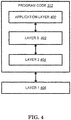
- FIG. 4 is a simplified block diagram of the program code 312 shown in FIG. 3 in accordance with one embodiment of the invention.
- the program code 312 includes an application layer 400, a Layer 3 portion 402, and a Layer 2 portion 404, and is coupled to a Layer 1 portion 406.
- the Layer 3 portion 402 generally performs radio resource control.
- the Layer 2 portion 404 generally performs link control.
- the Layer 1 portion 406 generally performs physical connections.
- 3GPP TS 38.885 introduced QoS (Quality of Service) management for NR V2X sidelink as follows:
- QoS management is relevant to V2X in the context of its use in resource allocation, congestion control, in-device coexistence, power control and SLRB configuration.
- Physical layer parameters related to QoS management are the priority, latency, reliability and minimum required communication range (as defined by higher layers) of the traffic being delivered. Data rate requirements are also supported in the AS.
- a SL congestion metric and, at least in resource allocation mode 2, mechanisms for congestion control are needed. It is beneficial to report the SL congestion metric to gNB.
- QoS parameters of V2X packets are provided by upper layers to the AS.
- the SLRBs are (pre-)configured based on the signalling flows and procedures shown in Figures 7-1 and 7-2.
- the per-flow QoS model described in [6] is assumed in upper layers.
- the PC5 QoS profile i.e. a set of specific PC5 QoS parameters, and PC5 QoS rule for each PC5 QoS flow are provisioned to the UE in advance by service authorization and provisioning procedures as in [6]; similarly, PC5 QoS profile for each QoS flow is also provisioned to the gNB/ng-eNB in advance. Then, when packet(s) arrive, the UE can first derive the identifier of the associated PC5 QoS flow(s) (i.e. PC5 QFI) based on the PC5 QoS rules configured in Step 0, and may then report the derived PC5 QFI(s) to the gNB/ng-eNB in Step 3.
- PC5 QoS flow(s) i.e. PC5 QFI
- the gNB/ng-eNB can derive the QoS profile(s) of these reported PC5 QFI(s) based on the provisioning from 5GC in Step 0, and may signal the configurations of the SLRB(s) associated with the PC5 QFI(s) UE reported via RRC dedicated signalling in Step 4.
- These SLRB configurations may include PC5 QoS flow to SLRB mapping, SDAP/PDCP/RLC/LCH configurations, etc.
- Step 5 the UE in the AS establishes SLRB(s) associated with the PC5 QFI(s) of the packet(s) with the peer UE as per gNB/ng-eNB configuration, and maps available packet(s) to the SLRB(s) established. SL unicast transmission can then occur.
- the purpose of this procedure is to inform E-UTRAN that the UE is interested or no longer interested to receive sidelink communication or discovery, to receive V2X sidelink communication, as well as to request assignment or release of transmission resources for sidelink communication or discovery announcements or V2X sidelink communication or sidelink discovery gaps, to report parameters related to sidelink discovery from system information of inter-frequency/PLMN cells and to report the synchronization reference used by the UE for V2X sidelink communication.
- a UE capable of sidelink communication or V2X sidelink communication or sidelink discovery that is in RRC_CONNECTED may initiate the procedure to indicate it is (interested in) receiving sidelink communication or V2X sidelink communication or sidelink discovery in several cases including upon successful connection establishment, upon change of interest, upon change to a PCell broadcasting SystemInformationBlockType18 or SystemInformationBlockType19 or SystemInformationBlockType21 including sl-V2X-ConfigCommon.
- a UE capable of sidelink communication or V2X sidelink communication or sidelink discovery may initiate the procedure to request assignment of dedicated resources for the concerned sidelink communication transmission or discovery announcements or V2X sidelink communication transmission or to request sidelink discovery gaps for sidelink discovery transmission or sidelink discovery reception and a UE capable of inter-frequency/PLMN sidelink discovery parameter reporting may initiate the procedure to report parameters related to sidelink discovery from system information of inter-frequency/PLMN cells.
- the UE Upon initiating the procedure, the UE shall:
- the SidelinkUEInformation message is used for the indication of sidelink information to the eNB.
- carrierFreqCommTx Indicates the index of the frequency on which the UE is interested to transmit V2X sidelink communication.
- the value 1 corresponds to the frequency of first entry in v2x-InterFreqInfoList broadcast in SIB21
- the value 2 corresponds to the frequency of second entry in v2x-InterFreqInfoList broadcast in SIB21 and so on.
- the value 0 corresponds the PCell's frequency.
- commRxInterestedFreq Indicates the frequency on which the UE is interested to receive sidelink communication.
- commTxResourceReq Indicates the frequency on which the UE is interested to transmit non-relay related sidelink communication as well as the one-to-many sidelink communication transmission destination(s) for which the UE requests E-UTRAN to assign dedicated resources.
- reliabilityInfoListSL Indicates the reliability(ies) (i.e., PPPRs [9]) associated with the reported traffic to be transmitted for V2X sidelink communication.
- v2x-CommRxInterestedFreqList Indicates the index(es) of the frequency(ies) on which the UE is interested to receive V2X sidelink communication.
- the value 1 corresponds to the frequency of first entry in v2x-InterFreqInfoList broadcast in SIB21
- the value 2 corresponds to the frequency of second entry in v2x-InterFreqInfoList broadcast in SIB21 and so on.
- the value 0 corresponds the PCell's frequency.
- v2x-DestinationInfoList Indicates the destination(s) for V2X sidelink communication.
- v2x-TypeTxSync Indicates the synchronization reference used by the UE.
- UE A and UE B use the same pair of Layer-2 IDs for subsequent PC5-S signalling message exchange and V2X service data transmission as specified in clause 5.6.1.4.
- the V2X layer of the transmitting UE indicates to the AS layer whether a transmission is for a PC5-S signalling message (i.e. Direct Communication Request/Accept, Link Identifier Update Request/Response, Disconnect Request/Response, Link Modification Request/Accept) or V2X service data.
- a UE For every PC5 unicast link, a UE self-assigns a distinct PC5 Link Identifier that uniquely identifies the PC5 unicast link in the UE for the lifetime of the PC5 unicast link.
- Each PC5 unicast link is associated with a Unicast Link Profile which includes:
- the Application Layer IDs and Layer-2 IDs may change as described in clauses 5.6.1.1 and 6.3.3.2 during the lifetime of the PC5 unicast link and, if so, shall be updated in the Unicast Link Profile accordingly.
- the UE uses PC5 Link Identifier to indicate the PC5 unicast link to V2X Application layer, therefore V2X Application layer identifies the corresponding PC5 unicast link even if there are more than one unicast link associated with one service type (e.g. the UE establishes multiple unicast links with multiple UEs for a same service type).
- the Unicast Link Profile shall be updated accordingly after a Layer-2 link modification for an established PC5 unicast link as specified in clause 6.3.3.4.
- the QoS handling is defined in TS 23.285 [8], based on ProSe Per-Packet Priority (PPPP) and ProSe Per-Packet Reliability (PPPR).
- PPPP ProSe Per-Packet Priority
- PPPR ProSe Per-Packet Reliability
- NR based PC5 For NR based PC5, a QoS model similar to that defined in TS 23.501 [6] for Uu reference point is used, i.e. based on 5Qls, with additional parameter of Range.
- a PC5 QoS Flow is associated with a PC5 QoS Rule that contains the PC5 QoS parameters as defined in clause 5.4.2.
- a set of standardized PC5 5Qls (PQI) are defined in clause 5.4.4.
- the UE may be configured with a set of default PC5 QoS parameters to use for the V2X services, as defined in clause 5.1.2.1.
- the UE determines if there is any existing PC5 QoS Flow matching the service data or request, i.e. based on the PC5 QoS Rules for the existing PC5 QoS Flow(s).
- the UE derives PC5 QoS parameters based on the V2X Application Requirements provided by the V2X application layer (if available) and the V2X service type (e.g. PSID or ITS-AID) according to the PC5 QoS mapping configuration defined in clause 5.1.2.1.
- the UE creates a new PC5 QoS Flow for the derived PC5 QoS parameters.
- the UE then assigns a PFI and derives PC5 QoS Rule for this PC5 QoS Flow.
- the PC5 QoS Flow is the finest granularity of QoS differentiation in the same destination identified by Destination Layer-2 ID.
- User Plane traffic with the same PFI receives the same traffic forwarding treatment (e.g. scheduling, admission threshold).
- the PFI is unique within a same destination.
- a PC5 QoS Context includes PC5 QoS parameters (e.g. PQI and Range) and the V2X service type (e.g. PSID or ITS-AID).
- PC5 QoS parameters e.g. PQI and Range
- V2X service type e.g. PSID or ITS-AID.
- the UE assigns a new PFI for V2X service the UE stores it with the corresponding PC5 QoS Context and PC5 QoS Rules for the destination.
- the UE releases the PFI the UE removes the corresponding PC5 QoS Context and PC5 QoS Rules for the destination.
- the Unicast Link Profile defined in clause 5.2.1.4 contains addition information mapped from PFI for unicast operation.
- the PC5 QoS Rule contains the PFI of the associated PC5 QoS Flow, a precedence value, and a PC5 Packet Filter Set as defined in clause 5.4.1.1.4.
- the precedence value determines the order in which the PC5 QoS Rules are evaluated.
- the PC5 QoS Rule with lower precedence value is evaluated before those with the higher precedence values.
- the V2X layer provides information for PC5 QoS operations per destination (e.g. identified by Destination Layer-2 ID) to AS layer for Per-flow QoS model operations as below:
- the V2X layer also provides the communication mode (e.g. broadcast, groupcast, unicast), radio frequencies, Tx Profile to the AS layer for the PC5 operation.
- the radio frequencies and Tx Profile are determined based on the V2X service type.
- the V2X layer ensures that V2X services (e.g. identified by PSID or ITS-AID) associated with different radio frequencies are classified into distinct PC5 QoS Flows.
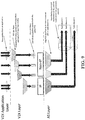
- Figure 5.4.1.1.3-1 illustrated an example of the classification and marking of user plane traffic using the PC5 QoS Rules, and the mapping of PC5 QoS Flows to radio resources at access stratum layer.
- the AS layer can determine the mapping of multiple PC5 QoS Flows to the same radio bearer based on the information provided. For broadcast and groupcast, the L2 link goes to all UEs in proximity identified by the destination Layer-2 ID.
- IP and Non-IP PDCP SDU types are supported for the V2X communication over PC5.
- IP PDCP SDU type For IP PDCP SDU type, only IPv6 is supported.
- IP address allocation and configuration are as defined in clause 5.6.1.1.
- the Non-IP PDCP SDU contains a Non-IP Type header, which indicates the V2X message family used by the application layer, e.g. IEEE 1609 family's WSMP [18], ISO defined FNTP [19].
- the Non-IP Type header and allowed values will be defined in stage 3 specification.
- the UE To perform unicast mode of V2X communication over PC5 reference point, the UE is configured with the related information as described in clause 5.1.2.1.
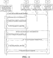
- Figure 6.3.3.1-1 shows the layer-2 link establishment procedure for unicast mode of V2X communication over PC5 reference point.
- the Direct Communication Accept message includes:
- both UEs i.e. the initiating UE and the target UE selected to use link-local IPv6 address, they shall disable the duplicate address detection defined in RFC 4862 [21].
- the source Layer-2 ID used to send the Direct Communication Accept message is determined as specified in clauses 5.6.1.1 and 5.6.1.4.
- the destination Layer-2 ID is set to the source Layer-2 ID of the received Direct Communication Request message.
- UE-1 Upon receiving the Direct Communication Accept message from peer UE, UE-1 obtains the peer UE's Layer-2 ID for future communication, for signalling and data traffic for this unicast link.
- the V2X layer of the UE that established PC5 unicast link passes the PC5 Link Identifier assigned for the unicast link and PC5 unicast link related information down to the AS layer.
- the PC5 unicast link related information includes Layer-2 ID information (i.e. source Layer-2 ID and destination Layer-2 ID). This enables the AS layer to maintain the PC5 Link Identifier together with the PC5 unicast link related information.
- Steps for mutual authentication and security association establishment will be determined based on feedback from SA WG3.
- V2X service data is transmitted over the established unicast link as below:
- the PC5 Link Identifier and PFI are provided to the AS layer, together with the V2X service data.
- UE-1 sends the V2X service data using the source Layer-2 ID (i.e. UE-1's Layer-2 ID for this unicast link) and the destination Layer-2 ID (i.e. the peer UE's Layer-2 ID for this unicast link).
- the source Layer-2 ID i.e. UE-1's Layer-2 ID for this unicast link
- the destination Layer-2 ID i.e. the peer UE's Layer-2 ID for this unicast link
- PC5 unicast link is bi-directional, therefore the peer UE of UE-1 can send the V2X service data to UE-1 over the unicast link with UE-1.
- the parameters included in the Direct Communication Request/Accept messages can be updated depending on RAN WGs' decision on how the Direct Communication Request/Accept messages are sent by the AS layer (e.g. by using PC5-RRC signalling).
- Figure 6.3.3.3-1 shows the layer-2 link release procedure over PC5 reference point.
- the V2X layer of each UE informs the AS layer that the unicast link has been released. This enables the AS layer to delete the context related to the released unicast link.
- Figure 6.3.3.4-1 shows the layer-2 link modification procedure for a unicast link. This procedure is used to:
- the Link Modification Accept message includes:
- the V2X layer of each UE provides information about the unicast link modification to the AS layer. This enables the AS layer to update the context related to the modified unicast link.
- 3GPP RAN2#106 made following agreements: Agreements on NR SL QoS and SLRB configurations: 1: Stick to SI phase conclusion that SLRB configurations should be NW-configured and/or pre-configured for NR SL. 2: For an RRC_CONNECTED UE, for transmission of a new PC5 QoS flow, it may report the QoS information of the PC5 QoS flow via RRC dedicated signalling to the gNB/ng-eNB. FFS on the exact timing about when UE initiates.
- the gNB/ng-eNB may provide SLRB configurations and configure the mapping of PC5 QoS flow to SLRB via RRC dedicated signalling, based on the QoS information reported by the UE.
- the UE can establishes/reconfigures the SLRB only after receiving the SLRB configuration.
- FFS when the UE establishes/reconfigures the SLRB.
- the gNB/ng-eNB may provide SLRB configurations and configure the PC5 QoS profile to SLRB mapping via V2X-specific SIB.
- an RRC_IDLE/INACTIVE UE initiates the transmission of a new PC5 QoS flow, it establishes the SLRB associated with the PC5 QoS profile of that flow based on SIB configuration.
- SLRB configurations and the mapping of PC5 QoS profile to SLRB are pre-configured.
- an OoC UE initiates the transmission of a new PC5 QoS flow, it establishes the SLRB associated with the flow based on pre-configu ration.
- FFS what is used to realize for PC5 QoS flow to SLRB mapping in pre-configuration (e.g. PFI to SLRB mapping, QoS profile to SLRB mapping, etc.), depending on SA2 conclusion on how PFI is assigned.
- the NW-configured/pre-configured SLRBs configurations include the SLRB parameters that are only related to TX, as well as the SLRB parameters that are related to both TX and RX and need to be aligned with the peer UEs.
- the initiating UE informs the peer UE of SLRB parameters that are related to both TX and RX and need to be aligned with the peer UEs.
- FFS on the detailed parameters.
- For SL unicast do not allow a UE to configure "SLRB parameters only related to TX" for the peer UE in SL via PC5 RRC message. FFS how to handle SRLB parameters only related to RX.
- the NW-configured/preconfigured SLRBs include the SLRB parameters that are only related to TX. 13: Those SLRB parameters which are related to both TX and RX and thus need to be aligned between a UE and all its peer UE(s) should be fixed in the Spec for SL groupcast and broadcast. 14: For SL broadcast, how to set SLRB parameters only related to RX is up to UE implementation. FFS for groupcast case. 15: SLRB configurations should be (pre-)configured for SL unicast, groupcast/broadcast separately (e.g. SLRB-ConfigForUnicast, SLRB-ConfigForGroupcast, SLRB-ConfigForBroadcast). FFS on the need of separate SLRB configurations between groupcast and broadcast.
- Figure 6.2.2.3 - 1 shows the format of SDAP Data PDU of UL with SDAP header being configured.
- the QFI field indicates the ID of the QoS flow (3GPP TS 23.501 [4]) to which the SDAP PDU belongs.
- the UE shall perform the following actions upon reception of the RRCReconfiguration:
- the UE shall perform the following actions based on a received RadioBearerConfig IE:
- the UE shall:
- the UE shall:
- the UE When determining whether a drb-Identity value is part of the current UE configuration, the UE does not distinguish which RadioBearerConfig and DRB-ToAddModList that DRB was originally configured in. To re-associate a DRB with a different key (K eNB to S-K gNB or vice versa), the network provides the drb-Identity value in the (target) drb-ToAddModList and sets the reestablishPDCP flag. The network does not list the drb-Identity in the (source) drb-ToReleaseList.
- the network When setting the reestablishPDCP flag for a radio bearer, the network ensures that the RLC receiver entities do not deliver old PDCP PDUs to the re-established PDCP entity. It does that e.g. by triggering a reconfiguration with sync of the cell group hosting the old RLC entity or by releasing the old RLC entity.
- UE configuration refers to the parameters configured by NR RRC unless otherwise stated.
- Ciphering and integrity protection can be enabled or disabled for a DRB.
- the enabling/disabling of ciphering or integrity protection can be changed only by releasing and adding the DRB.
- the IE SDAP-Config is used to set the configurable SDAP parameters for a data radio bearer. All configured instances of SDAP-Config with the same value of pdu-Session correspond to the same SDAP entity as specified in TS 37.324 [24]. SDAP-Config field descriptions defaultDRB Indicates whether or not this is the default DRB for this PDU session. Among all configured instances of SDAP-Config with the same value of pdu-Session, this field shall be set to true in at most one instance of SDAP-Config and to false in all other instances.
- mappedQoS-FlowsToAdd Indicates the list of QFIs of UL QoS flows of the PDU session to be additionally mapped to this DRB.
- a QFI value can be included at most once in all configured instances of SDAP-Config with the same value of pdu-Session.
- the QFI value of the remapped QoS flow is only included in mappedQoS-FlowsToAdd in sdap-Config corresponding to the new DRB and not included in mappedQoS-FlowsToRelease in sdap-Config corresponding to the old DRB.
- mappedQoS-FlowsToRelease Indicates the list of QFIs of QoS flows of the PDU session to be released from existing QoS flow to DRB mapping of this DRB.
- sdap-HeaderUL Indicates whether or not a SDAP header is present for UL data on this DRB. The field cannot be changed after a DRB is established. The network sets this field to present if the field defaultDRB is set to true.
- sdap-HeaderDL Indicates whether or not a SDAP header is present for DL data on this DRB. The field cannot be changed after a DRB is established.
- a paired UEs may establish one or more unicast links between each other.
- Each unicast link is associated with an Application Layer ID of a UE and an Application Layer ID of a peer UE.
- one or more V2X services may transfer traffic through one unicast link. Since different V2X services require different QoS requirements, each V2X service may have one or more PC5 QoS flows for traffic transfer. Therefore, each unicast link may have one or more PC5 QoS flows belonging to different V2X services.
- each UE needs to maintain a mapping of PC5 QoS flow identity (PFI) to PC5 QoS Context and PC5 QoS Rules per destination associated with the unicast link.
- PFI PC5 QoS flow identity
- the PC5 QoS Context includes PC5 QoS parameters (e.g. PQI, etc.), an identity used to identify a V2X service (e.g. PSID) and/or an identity used to identify a V2X application (e.g. ITS-AID) offering the V2X service for the associated PFI.
- PC5 QoS parameters e.g. PQI, etc.
- PSID an identity used to identify a V2X service
- ITS-AID identity used to identify a V2X application offering the V2X service for the associated PFI.
- UE1 and UE2 establish two unicast links, Unicast Link #1 and #2.
- UE2 uses a first Layer-2 ID as a Destination Layer-2 ID 1 for Unicast Link #1 and a second Layer-2 ID as another Destination Layer-2 ID 2 for Unicast Link #2.
- V2X Service A has two PC5 QoS flows, PFI1 and PFI2.
- V2X Service B has one PC5 QoS flow, PFI3.
- V2X Service C has one PC5 QoS flow, PFI4.
- V2X Service D has one PC5 QoS flow, PFI5.
- the UE for transmission of a new PC5 QoS flow, may report the QoS information (e.g. PQI) of the PC5 QoS flow to the gNB. And then the gNB may provide a SLRB configuration and configure a mapping of PC5 QoS flow to SLRB to the UE based on the QoS information reported by the UE. Therefore, the UE may transmit a request message to gNB to request a SLRB configuration for a PC5 QoS flow of one V2X service. In case there are multiple V2X services supported over the same unicast link, how to release SLRB(s) associated with a V2X service should be considered when this V2X service is deactivated.
- the QoS information e.g. PQI
- UE1 may send an identity or index of a destination associated with one or more PC5 QoS flows to the gNB to request SLRB configuration.
- the destination identity or index could be included in a request for SLRB configuration.
- the destination identity or index could be included in a SidelinkUEInformation.
- the destination index may indicate an entry in a destination list. Each entry in the destination list may include a destination (identified by a Destination Layer-2 ID).
- the gNB configures the mapping of PFIs and SLRBs.
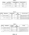
- the relationship among destination identity/index, PFI, and PQI could be illustrated in Table 1 shown in FIG. 15 .
- the gNB may provide mappings of PFIs to SLRBs as follows:
- PFI2 and PFI3 belong to different V2X services but the gNB may map them to SLRB2 due to e.g. PQI 2 and PQI 3 share similar PC5 QoS requirements.
- each SLRB is used to serve only one V2X service.
- V2X service type e.g. identity of a V2X service (PSID) or identity of a V2X application offering a V2X service (ITS-AID)
- PSID identity of a V2X service
- ITS-AID identity of a V2X application offering a V2X service
- each destination in one entry of the destination list may be associated with a PFI list, and each entry of the PFI list includes an identity of PC5 QoS flow, a PQI and a V2X service type.
- the relationship among destination identity or index, PFI, PQI and V2X service type could be illustrated in Table 2a shown in FIG. 16 .
- V2X service type could be the identity of a V2X service or the identity of the V2X application offering the V2X service that needs more bits for transmission
- alternative for reducing signalling overhead can be considered.
- the UE could group one or more PC5 QoS flows belonging to the same V2X service as one set of PC5 QoS flow e.g. one PFI set.
- Each index or identity used to identify one PFI set could be assigned by the UE. Therefore, bits required for indicating one PFI set will be less than bits required for indicating one V2X service type.
- the index or identity used to identify one PFI set can be included in each entry of the destination list.
- each destination in one entry of the destination list may be associated with a PFI list, and each entry of the PFI list includes an identity of PC5 QoS flow, a PQI and an identity or index of one PFI set.
- the relationship among destination identity or index, PFI, PQI and PFI set could be illustrated in Table 2b shown in FIG. 16 .
- the gNB can configure the mapping of PFIs and SLRBs as follows:
- the PFI(s) associated with the V2X service will be not needed and the SLRB(s) corresponding to the PFI(s) should be released.
- the PC5 QoS flows PFI1 and PFI 2 are not needed and the SLRB(s) used to serve PFI1 and PFI2 should be released.
- SLRB1 used to serve PFI1 should be released. If SLRB2 is used to serve only PFI2, it should be released; otherwise, if SLRB2 is used to serve PFI2 and PFI3, it should not be released because SLRB2 can be still used for traffic transfer of V2X Service B.
- the gNB needs to know which V2X service has been terminated or deactivated by the UE or which SLRB(s) is not needed by the UE.
- the UE may indicate particular PC5 QoS flow(s) for a destination is not needed by updating the entry of the destination in the destination list (e.g. removing the PFI(s) associated with the destination and/or any information associated with the PFI(s)). If the destination has only one V2X service that is terminated, the entry of the destination can be removed from the updated destination list.
- UE1 can remove PFI1 and PFI2 from the corresponding entry in the destination list and sends this updated destination list to the gNB. Based on the updated destination list, the gNB can release the SLRB(s) used to serve PFI1 and PFI2.
- the UE could release a SLRB and some transmission related configuration (e.g. a logical channel associated with the SLRB, mapping of the logical channel to a logical channel group, and etc.) by itself if the SLRB serves one or more PC5 QoS flows belonging to the same V2X service.
- the UE may not release a SLRB and some transmission related configuration (e.g. a logical channel associated with the SLRB, mapping of the logical channel to a logical channel group, and etc.) by itself if the SLRB serves one or more PC5 QoS flows belonging to different V2X services.
- the UE could release a SLRB and some transmission related configuration (e.g. a logical channel associated with the SLRB, mapping of the logical channel to a logical channel group, and etc.) based on an indication received from the gNB after the updated destination list is transmitted to the gNB.
- the indication could indicate which SLRB should be released.
- the indication could indicate the SLRB to be released belongs to which destination.
- the indication could be a RRC (Radio Resource Control) reconfiguration message.
- RRC Radio Resource Control
- Examples of the updated destination list could be illustrated in the following Tables 3a - 3c shown in FIG. 17 .
- the UE could indicate the gNB about which PC5 QoS flow or which SLRB to be released.
- the UE could transmit a release message to the gNB for releasing SLRB configuration when a V2X service is terminated.
- This concept may also be applied to cases where there is only one V2X service supported on the unicast link. In this situation, each PC5 QoS flow may be deactivated or terminated by upper layers individually and thus the SLRB mapped to the concerned PC5 QoS flow(s) may be released.
- the release message may indicate a destination (via e.g. Destination Layer-2 ID) or a unicast link (via e.g. PC5 Link Identifier) for associating the PC5 QoS flow or SLRB to be released.
- the release message may include one or more following information:
- a V2X service identity is an identity of the V2X service, which may be a PSID.
- a UE may assign an index to a V2X service when it is activated in the UE. For example, the UE may assign index "1" to the first V2X service and index "2" to the second V2X service.
- a V2X service index is expressed with less bits than a V2X service identity and thus could consume less signalling overhead.
- the UE does not need to send the whole destination list again so that signalling overhead can be reduced.
- Examples of the release message could be illustrated in Tables 4a-4d shown in FIG. 18 respectively, where the second entry in Table 4b (shown in FIG. 18 ) is present if SLRB2 serves multiple V2X services and is not present if SLRB2 serves only one V2X service.
- the destination could not be included in the release message if the PFI to be removed is differentiable among different destinations.
- Example of the release message could be illustrated in Table 5a shown in FIG. 19 .
- the destination could not be included in the release message if the SLRB to be released is differentiable among different destinations.
- Example of the release message could be illustrated in Table 5b shown in FIG. 19 .
- the second entry in this table is present if SLRB2 serves multiple V2X services and is not present if SLRB2 serves only one V2X service.
- the destination could not be included in the release message if the PFI to be removed is grouped based on V2X service type or PFI set. Examples of the release message could be illustrated in Tables 5c and 5d shown in FIG. 19 .
- FIG. 20 is a flow chart 2000 according to one exemplary embodiment from the perspective of a first UE to indicate a network node for releasing SLRB or SL-DRB.
- the first UE transmits a first RRC message to a network node for requesting sidelink resource, wherein the first RRC message includes a PFI of a PC5 QoS flow in a first list of PC5 QoS flows.
- the first UE receives a second RRC message from the network node, wherein the second RRC message configures a SLRB and maps the PC5 QoS flow to the SLRB.
- step 2015 the first UE transmits a third RRC message to the network node if the PC5 QoS flow is deactivated or released, wherein the PFI of the PC5 QoS flow is removed from a second list of PC5 QoS flows included in the third RRC message.
- the PC5 QoS flow could be transmitted on a PC5 unicast link and the PC5 unicast link is established between the first UE and a second UE.
- the first UE could also receive a fourth RRC message from the network node, wherein the fourth RRC message reconfigures the UE to release the SLRB. Furthermore, the first UE could release the SLRB according to the fourth RRC message.
- the PFI of the PC5 QoS flow may not be included in the second list of PC5 QoS flows.
- the first RRC message may include a destination Layer-2 ID associated with the PC5 unicast link.
- the destination Layer-2 ID may be a Layer-2 ID of the second UE.
- the first RRC message or the third RRC message could be a SidelinkUEInformation.
- the second RRC message or the fourth RRC message could be a RRC reconfiguration message.
- the network node could be a base station (e.g. gNB).
- gNB base station
- the first UE 300 includes a program code 312 stored in the memory 310.
- the CPU 308 could execute program code 312 to enable the first UE (i) to transmit a first RRC message to a network node for requesting sidelink resource, wherein the first RRC message includes a PFI of a PC5 QoS flow in a first list of PC5 QoS flows, (ii) to receive a second RRC message from the network node, wherein the second RRC message configures a SLRB and maps the PC5 QoS flow to the SLRB, and (iii) to transmit a third RRC message to the network node if the PC5 QoS flow is deactivated or released, wherein the PFI of the PC5 QoS flow is removed from a second list of PC5 QoS flows included in the third RRC message.
- the CPU 308 can execute the program code 312 to perform all of the above-de
- FIG. 21 is a flow chart 2100 according to one exemplary embodiment from the perspective of a UE to indicate a network node for releasing SLRB.
- the UE receives a second RRC message from the network node, wherein the second RRC message configures a first SLRB associated with one or more PFIs belonging to a first V2X service or a first PFI set and a second SLRB associated with one or more PFIs belonging to a second V2X service or a second PFI set.
- the UE transmits a third RRC message to the network node if the first V2X service is deactivated or terminated, wherein the third RRC message indicates the first SLRB for release.
- the UE could transmit a first RRC message to the network node, wherein the first RRC message includes the one or more PFIs associated with the first V2X service or the first PFI set and the one or more PFIs associated with the second V2X service or the second PFI set.
- the UE could also receive a fourth RRC message from the network node, wherein the fourth RRC message reconfigures the UE to release the first SLRB.
- the first RRC message may include a Layer-2 ID list.
- An entry of the Layer-2 ID list may include a first Layer-2 ID and a first PC5 QoS flow list associated with the first Layer-2 ID, and an entry of the first PC5 QoS flow list may indicate the first V2X service or the first PFI set.
- An entry of the Layer-2 ID list may also include a second Layer-2 ID and a second PC5 QoS flow list associated with the second Layer-2 ID, and an entry of the second PC5 QoS flow list may indicate the second V2X service or the second PFI set.
- the first Layer-2 ID could be the same as the second Layer-2 ID.
- the first PC5 QoS flow list could also be the same as the second PC5 QoS flow list.
- the first or second Layer-2 ID list could be a Source Layer-2 ID list or a Destination Layer-2 ID list.
- the first or second Layer-2 ID could also be a Source Layer-2 ID if the first/second Layer-2 ID belongs to the UE.
- the first or second Layer-2 ID could be a Destination Layer-2 ID if the first or second Layer-2 ID belongs to a peer UE of the UE.
- the first RRC message could be a request message for SLRB configuration.
- the first RRC message could also be a SidelinkUEInformation.
- the second or fourth RRC message could be a RRC reconfiguration message.
- the third RRC message could be a release message for SLRB configuration.
- the third RRC message may include the one or more PFIs associated with the second V2X service or the second PFI set, but may not include the one or more PFIs associated with the first V2X service or the first PFI set.
- the entry of the Layer-2 ID list including the first Layer-2 ID and the first PC5 QoS flow list could be removed from the Layer-2 ID list in the third RRC message.
- the entry of the first PC5 QoS flow list indicating the first V2X service or the first PFI set could be removed from the Layer-2 ID list in the third RRC message.
- the third RRC message may include an identity of the first SLRB.
- the third RRC message may also include an identity of the first V2X service or an identity or index of the first PFI set.
- the UE and the peer UE could establish a first unicast link for serving the first V2X service.
- the UE and the peer UE could also establish a second unicast link for serving the second V2X service.
- the third RRC message may include a first PC5 Link Identifier used to identify the first unicast link.
- the network node could be a base station (e.g. gNB).
- gNB base station
- the UE 300 includes a program code 312 stored in the memory 310.
- the CPU 308 could execute program code 312 to enable the UE (i) to receive a second RRC message from the network node, wherein the second RRC message configures a first SLRB associated with one or more PFIs belonging to a first V2X service or a first PFI set and a second SLRB associated with one or more PFIs belonging to a second V2X service or a second PFI set, and (ii) to transmit a third RRC message to the network node if the first V2X service is deactivated or terminated, wherein the third RRC message indicates the first SLRB for release.
- the CPU 308 can execute the program code 312 to perform all of the above-described actions and steps or others described herein.
- FIG. 22 is a flow chart 2200 according to one exemplary embodiment from the perspective of a first UE to indicate a network node to release SLRB.
- the first UE establishes a unicast link with a second UE to support a first sidelink service, wherein at least one SLRB are configured by the network node to support the sidelink service.
- the first UE transmits a first RRC message, in response to deactivation of the sidelink service, to the network node, wherein the first RRC message includes information to indicate SLRB(s) for release.
- the first UE 300 includes a program code 312 stored in the memory 310.
- the CPU 308 could execute program code 312 to enable the first UE (i) to establish a unicast link with a second UE to support a first sidelink service, wherein at least one SLRB are configured by the network node to support the sidelink service, and (ii) to transmit a first RRC message, in response to deactivation of the sidelink service, to the network node, wherein the first RRC message includes information to indicate SLRB(s) for release.
- the CPU 308 can execute the program code 312 to perform all of the above-described actions and steps or others described herein.
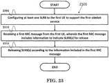
- FIG. 23 is a flow chart 2300 according to one exemplary embodiment from the perspective of a network node to release SLRB(s) configured to a first UE, wherein a unicast link is established between the first UE and a second UE to support a first sidelink service.
- the network node configures at least one SLRB to the first UE to support the first sidelink service.
- the network node receives a first RRC message from the first UE, wherein the first RRC message includes information to indicate SLRB(s) for release.
- the network node releases SLRB(s) according to the information included in the first RRC message.
- the network node 300 includes a program code 312 stored in the memory 310.
- the CPU 308 could execute program code 312 to enable the network node (i) to configure at least one SLRB to the first UE to support the first sidelink service, (ii) to receive a first RRC message from the first UE, wherein the first RRC message includes information to indicate SLRB(s) for release, and (iii) to release SLRB(s) according to the information included in the first RRC message.
- the CPU 308 can execute the program code 312 to perform all of the above-described actions and steps or others described herein.
- the information could be an identity or index of the first sidelink service.
- the information may include one or more PC5 QoS flows (PFIs) to indicate SLRBs mapped to the one or more PC5 QoS flows (PFIs) need to be released if the SLRB(s) are not shared by any PC5 QoS flow from other sidelink service.
- PFIs PC5 QoS flows
- the information may also include one or more identities of the at least one SLRB if SLRB(s) identified by the one or more identities are not shared by any PC5 QoS flow from other sidelink service.
- the first UE could release SLRB(s) according to the information included in the first RRC message. Also, the first UE could release SLRB(s) autonomously. The first UE could release SLRB(s) in response to reception of a second RRC message from the network node.
- the network node could transmit a second RRC message to the first UE for SLRB release.
- the second RRC message may include one or more identities of the at least one SLRB for release.
- the first UE could transmit a third RRC message to the network node to request SLRB configuration(s) for one or more of the at least one SLRB.
- the third RRC message may include at least one PC5 QoS flow (PFI).
- the third RRC message may also include a PC5 QoS identifier (PQI) associated with each PC5 QoS flow.
- the third RRC message may include an identity or index of the first sidelink service.
- the third RRC message may include a destination (Layer-2) identity and/or a PC5 Link Identifier (PFI).
- the network node could transmit a fourth RRC message to the first UE to configure SLRB configuration(s) for one or more of the at least one SLRB.
- the fourth RRC message may include one or more identities of the at least one SLRB.
- the fourth RRC message may also include an identity or index of the first sidelink service.
- the fourth RRC message may include a destination (Layer-2) identity and/or a PC5 Link Identifier (PFI).
- Layer-2 Layer-2
- PFI PC5 Link Identifier
- FIG. 24 is a flow chart 2400 according to one exemplary embodiment from the perspective of a first UE to indicate a network node to release SLRB or SL-DRB.
- the first UE receives a second RRC message from the network node, wherein the second RRC message configures a SLRB and maps one or more PC5 QoS flows to be transmitted on a unicast link to the SLRB, wherein the unicast link is established between the first UE and a second UE.
- the first UE transmits a third RRC message to the network node if the one or more PC5 QoS flows are deactivated or terminated, wherein the third RRC message includes information indicating the SLRB for release.
- the first UE could transmit a first RRC message to the network node for requesting a SLRB configuration, wherein the first RRC message includes PFI(s) of the one or more PC5 QoS flows.
- the first UE could receive a fourth RRC message from the network node, wherein the fourth RRC message reconfigures the UE to release the SLRB indicated by the information included in the third RRC message.
- the first RRC message may include a destination Layer-2 ID associated with the unicast link.
- the destination Layer-2 ID may be a source Layer-2 ID of the second UE.
- the first or third RRC message may be a SidelinkUEInformation.
- the second or fourth RRC message may be a RRC reconfiguration message.
- the third RRC message may be a release message for the SLRB.
- the third RRC message may include PFIs of the one or more PC5 QoS flows mapped to the SLRB for release.
- the third RRC message may include an identity of the SLRB for release or an index of a configuration configuring the SLRB for release.
- the network node could be a base station (e.g. gNB).
- gNB base station
- the first UE could release the SLRB according to the information included in the fourth RRC message.
- the first UE could release SLRB(s) autonomously.
- the third RRC message could be transmitted to the network node if upper layer of the first UE indicates the one or more PC5 QoS flows are deactivated or terminated or if upper layer of the first UE indicates the one or more PC5 QoS flow are not mapped to the SLRB.
- the one or more PC5 QoS flows may be associated with a V2X service.
- the third RRC message could indicate the PFIs of the one or more PC5 QoS flows mapped to the SLRB are removed from a list of PC5 QoS flow included in the first RRC message.
- the first RRC message may include PFI(s) of the one or more PC5 QoS flows.
- the first RRC message may also include a PC5 QoS identifier (PQI) and/or a PC5 QoS profile associated with each PC5 QoS flow.
- the first RRC message may include a destination (Layer-2) identity and/or a PC5 Link Identifier (PFI) associated with the unicast link.
- the second RRC message may include one or more identities of the at least one SLRB.
- the second RRC message may include a destination (Layer-2) identity, an index associated with the destination (Layer-2) identity and/or a PC5 Link Identifier (PFI) associated with the unicast link.
- Layer-2 Destination-2
- PFI PC5 Link Identifier
- the first UE 300 includes a program code 312 stored in the memory 310.
- the CPU 308 could execute program code 312 to enable the first UE (i) to receive a second RRC message from the network node, wherein the second RRC message configures a SLRB and maps one or more PC5 QoS flows to be transmitted on a unicast link to the SLRB, wherein the unicast link is established between the first UE and a second UE, and (ii) to transmit a third RRC message to the network node if the one or more PC5 QoS flows are deactivated or terminated, wherein the third RRC message includes information indicating the SLRB for release.
- the CPU 308 can execute the program code 312 to perform all of the above-described actions and steps or others described herein.
- FIG. 25 is a flow chart 2500 according to one exemplary embodiment from the perspective of a network node to release SLRB(s) configured to a first UE.
- the network node configures at least one SLRB to the first UE for a unicast link, wherein the unicast link is established between the first UE and a second UE.
- the network node receives a third RRC message from the first UE, wherein the third RRC message includes information to indicate a SLRB among the at least one SLRB for release.
- the network node releases configurations of the SLRB according to the information included in the third RRC message.
- the information may include PFI(s) of one or more PC5 QoS flows mapped to the SLRB for release.
- the information may also include an identity of the SLRB for release.
- the network node could transmit a fourth RRC message to the first UE for SLRB release.
- the fourth RRC message may include one or more identities of the SLRB for release.
- the first UE could transmit a first RRC message to the network node to request SLRB configuration(s) for the one or more PC5 QoS flows.
- the first RRC message may include PFI(s) of the one or more PC5 QoS flows.
- the first RRC message may also include a PC5 QoS identifier (PQI) and/or a PC5 QoS profile associated with each PC5 QoS flow.
- the first RRC message may include a destination (Layer-2) identity and/or a PC5 Link Identifier (PFI) associated with the unicast link.
- the information may indicate the PFIs of the one or more PC5 QoS flows mapped to the SLRB are removed from a list of PC5 QoS flow included in the first RRC message.
- the network node could transmit a second RRC message to the first UE to configure SLRB configuration(s) for one or more of the at least one SLRB.
- the second RRC message may include one or more identities of the at least one SLRB.
- the second RRC message may also include a destination (Layer-2) identity, an index associated with the destination (Layer-2) identity and/or a PC5 Link Identifier (PFI) associated with the unicast link.
- Layer-2 Layer-2
- PFI PC5 Link Identifier
- the first or third RRC message may be a SidelinkUEInformation.
- the second or fourth RRC message may be a RRC reconfiguration message.
- the network node 300 includes a program code 312 stored in the memory 310.
- the CPU 308 could execute program code 312 to enable the network node (i) to configure at least one SLRB to the first UE for a unicast link, wherein the unicast link is established between the first UE and a second UE, (ii) to receive a third RRC message from the first UE, wherein the third RRC message includes information to indicate a SLRB among the at least one SLRB for release, and (iii) to release configurations of the SLRB according to the information included in the third RRC message.
- the CPU 308 can execute the program code 312 to perform all of the above-described actions and steps or others described herein.
- concurrent channels could be established based on pulse repetition frequencies.
- concurrent channels could be established based on pulse position or offsets.
- concurrent channels could be established based on time hopping sequences.
- concurrent channels could be established based on pulse repetition frequencies, pulse positions or offsets, and time hopping sequences.
- the various illustrative logical blocks, modules, and circuits described in connection with the aspects disclosed herein may be implemented within or performed by an integrated circuit ("IC"), an access terminal, or an access point.
- the IC may comprise a general purpose processor, a digital signal processor (DSP), an application specific integrated circuit (ASIC), a field programmable gate array (FPGA) or other programmable logic device, discrete gate or transistor logic, discrete hardware components, electrical components, optical components, mechanical components, or any combination thereof designed to perform the functions described herein, and may execute codes or instructions that reside within the IC, outside of the IC, or both.
- a general purpose processor may be a microprocessor, but in the alternative, the processor may be any conventional processor, controller, microcontroller, or state machine.
- a processor may also be implemented as a combination of computing devices, e.g., a combination of a DSP and a microprocessor, a plurality of microprocessors, one or more microprocessors in conjunction with a DSP core, or any other such configuration.
- a software module e.g., including executable instructions and related data
- other data may reside in a data memory such as RAM memory, flash memory, ROM memory, EPROM memory, EEPROM memory, registers, a hard disk, a removable disk, a CD-ROM, or any other form of computer-readable storage medium known in the art.
- a sample storage medium may be coupled to a machine such as, for example, a computer/processor (which may be referred to herein, for convenience, as a "processor") such the processor can read information (e.g., code) from and write information to the storage medium.
- a sample storage medium may be integral to the processor.
- the processor and the storage medium may reside in an ASIC.
- the ASIC may reside in user equipment.
- the processor and the storage medium may reside as discrete components in user equipment.
- any suitable computer-program product may comprise a computer-readable medium comprising codes relating to one or more of the aspects of the disclosure.
- a computer program product may comprise packaging materials.
Landscapes
- Engineering & Computer Science (AREA)
- Computer Networks & Wireless Communication (AREA)
- Signal Processing (AREA)
- Quality & Reliability (AREA)
- Mobile Radio Communication Systems (AREA)
Abstract
Description
- This disclosure generally relates to wireless communication networks, and more particularly, to a method and apparatus for releasing sidelink radio bearer in a wireless communication system.
- With the rapid rise in demand for communication of large amounts of data to and from mobile communication devices, traditional mobile voice communication networks are evolving into networks that communicate with Internet Protocol (IP) data packets. Such IP data packet communication can provide users of mobile communication devices with voice over IP, multimedia, multicast and on-demand communication services.
- An exemplary network structure is an Evolved Universal Terrestrial Radio Access Network (E-UTRAN). The E-UTRAN system can provide high data throughput in order to realize the above-noted voice over IP and multimedia services. A new radio technology for the next generation (e.g., 5G) is currently being discussed by the 3GPP standards organization. Accordingly, changes to the current body of 3GPP standard are currently being submitted and considered to evolve and finalize the 3GPP standard.
- A method and apparatus are disclosed from the perspective of a first UE (User Equipment) to indicate a network node for releasing SLRB (Sidelink Radio Bearer) or SL-DRB (Sidelink-Data Radio Bearer) and are defined in the independent claims. The dependent claims define preferred embodiments thereof. In one embodiment, the method includes transmitting a first RRC (Radio Resource Control) message to a network node for requesting sidelink resource, wherein the first RRC message includes a PFI (PC5 QoS Flow Identifier) of a PC5 QoS (Quality of Service) flow in a first list of PC5 QoS flows. The method also includes receiving a second RRC message from the network node, wherein the second RRC message configures a SLRB and maps the PC5 QoS flow to the SLRB. The method further includes transmitting a third RRC message to the network node if the PC5 QoS flow is deactivated or released, wherein the PFI (PC5 QoS Flow Identifier) of the PC5 QoS flow is removed from a second list of PC5 QoS flows included in the third RRC message.
-
-
FIG. 1 shows a diagram of a wireless communication system according to one exemplary embodiment. -
FIG. 2 is a block diagram of a transmitter system (also known as access network) and a receiver system (also known as user equipment or UE) according to one exemplary embodiment. -
FIG. 3 is a functional block diagram of a communication system according to one exemplary embodiment. -
FIG. 4 is a functional block diagram of the program code ofFIG. 3 according to one exemplary embodiment. -
FIG. 5 is a reproduction of Figure 7-1 of 3GPP TS 38.885 V16.0.0. -
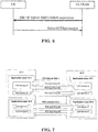
FIG. 6 is a reproduction of Figure 5.10.2-1 of 3GPP TS 36.331 V15.3.0. -
FIG. 7 is a reproduction of Figure 5.2.1.4-1 of 3GPP TR 23.786 V1.0.0. -
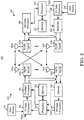
FIG. 8 is a reproduction of Figure 5.4.1.1.1-1 of 3GPP TR 23.786 V1.0.0. -
FIG. 9 is a reproduction of Figure 5.4.1.1.3-1 of 3GPP TR 23.786 V1.0.0. -
FIG. 10 is a reproduction of Figure 6.1.1-1 of 3GPP TR 23.786 V1.0.0. -
FIG. 11 is a reproduction of Figure 6.3.3.1-1 of 3GPP TR 23.786 V1.0.0. -
FIG. 12 is a reproduction of Figure 6.3.3.3-1 of 3GPP TR 23.786 V1.0.0. -
FIG. 13 is a reproduction of Figure 6.3.3.4-1 of 3GPP TR 23.786 V1.0.0. -
FIG. 14 is a reproduction of Figure 6.2.2.3-1 of 3GPP TS 37.324 V15.1.0. -
FIG. 15 shows Table 1 according to one exemplary embodiment. -
FIG. 16 shows Tables 2a and 2b according to exemplary embodiments. -
FIG. 17 shows Tables 3a, 3b, and 3c according to exemplary embodiments. -
FIG. 18 shows Tables 4a, 4b, 4c, and 4d according to exemplary embodiments. -
FIG. 19 shows Tables 5a, 5b, 5c, and 5d according to exemplary embodiments. -
FIG. 20 is a flow chart according to one exemplary embodiment. -
FIG. 21 is a flow chart according to one exemplary embodiment. -
FIG. 22 is a flow chart according to one exemplary embodiment. -
FIG. 23 is a flow chart according to one exemplary embodiment. -
FIG. 24 is a flow chart according to one exemplary embodiment. -
FIG. 25 is a flow chart according to one exemplary embodiment. - The exemplary wireless communication systems and devices described below employ a wireless communication system, supporting a broadcast service. Wireless communication systems are widely deployed to provide various types of communication such as voice, data, and so on. These systems may be based on code division multiple access (CDMA), time division multiple access (TDMA), orthogonal frequency division multiple access (OFDMA), 3GPP LTE (Long Term Evolution) wireless access, 3GPP LTE-A or LTE-Advanced (Long Term Evolution Advanced), 3GPP2 UMB (Ultra Mobile Broadband), WiMax, 3GPP NR (New Radio), or some other modulation techniques.
- In particular, the exemplary wireless communication systems devices described below may be designed to support one or more standards such as the standard offered by a consortium named "3rd Generation Partnership Project" referred to herein as 3GPP, including: TR 23.786 V1.0.0, "Architecture enhancements for 5G System (5GS) to support Vehicle-to-Everything (V2X) services (Release 16)"; TS 36.331 V15.3.0, "E-UTRA; Radio Resource Control (RRC) Protocol specification (Release 15)"; TS 23.287 V110, "Architecture enhancements for 5G System (5GS) to support Vehicle-to-Everything (V2X) services";
3GPP RAN2# 106 Chairman's note; TS 38.885 V16.0.0, "NR; Study on NR Vehicle-to-Everything (V2X) (Release 16) -
FIG. 1 shows a multiple access wireless communication system according to one embodiment of the invention. An access network 100 (AN) includes multiple antenna groups, one including 104 and 106, another including 108 and 110, and an additional including 112 and 114. InFIG. 1 , only two antennas are shown for each antenna group, however, more or fewer antennas may be utilized for each antenna group. Access terminal 116 (AT) is in communication withantennas antennas terminal 116 overforward link 120 and receive information fromaccess terminal 116 overreverse link 118. Access terminal (AT) 122 is in communication withantennas antennas forward link 126 and receive information from access terminal (AT) 122 overreverse link 124. In a FDD system,communication links forward link 120 may use a different frequency then that used byreverse link 118. - Each group of antennas and/or the area in which they are designed to communicate is often referred to as a sector of the access network. In the embodiment, antenna groups each are designed to communicate to access terminals in a sector of the areas covered by
access network 100. - In communication over
forward links access network 100 may utilize beamforming in order to improve the signal-to-noise ratio of forward links for thedifferent access terminals - An access network (AN) may be a fixed station or base station used for communicating with the terminals and may also be referred to as an access point, a Node B, a base station, an enhanced base station, an evolved Node B (eNB), or some other terminology. An access terminal (AT) may also be called user equipment (UE), a wireless communication device, terminal, access terminal or some other terminology.
-
FIG. 2 is a simplified block diagram of an embodiment of a transmitter system 210 (also known as the access network) and a receiver system 250 (also known as access terminal (AT) or user equipment (UE)) in aMIMO system 200. At thetransmitter system 210, traffic data for a number of data streams is provided from adata source 212 to a transmit (TX)data processor 214. - Preferably, each data stream is transmitted over a respective transmit antenna. TX
data processor 214 formats, codes, and interleaves the traffic data for each data stream based on a particular coding scheme selected for that data stream to provide coded data. - The coded data for each data stream may be multiplexed with pilot data using OFDM techniques. The pilot data is typically a known data pattern that is processed in a known manner and may be used at the receiver system to estimate the channel response. The multiplexed pilot and coded data for each data stream is then modulated (i.e., symbol mapped) based on a particular modulation scheme (e.g., BPSK, QPSK, M-PSK, or M-QAM) selected for that data stream to provide modulation symbols. The data rate, coding, and modulation for each data stream may be determined by instructions performed by
processor 230. - The modulation symbols for all data streams are then provided to a
TX MIMO processor 220, which may further process the modulation symbols (e.g., for OFDM).TX MIMO processor 220 then provides NT modulation symbol streams to NT transmitters (TMTR) 222a through 222t. In certain embodiments,TX MIMO processor 220 applies beamforming weights to the symbols of the data streams and to the antenna from which the symbol is being transmitted. - Each transmitter 222 receives and processes a respective symbol stream to provide one or more analog signals, and further conditions (e.g., amplifies, filters, and upconverts) the analog signals to provide a modulated signal suitable for transmission over the MIMO channel. NT modulated signals from
transmitters 222a through 222t are then transmitted from NT antennas 224a through 224t, respectively. - At
receiver system 250, the transmitted modulated signals are received by NR antennas 252a through 252r and the received signal from each antenna 252 is provided to a respective receiver (RCVR) 254a through 254r. Each receiver 254 conditions (e.g., filters, amplifies, and downconverts) a respective received signal, digitizes the conditioned signal to provide samples, and further processes the samples to provide a corresponding "received" symbol stream. - An
RX data processor 260 then receives and processes the NR received symbol streams from NR receivers 254 based on a particular receiver processing technique to provide NT "detected" symbol streams. TheRX data processor 260 then demodulates, deinterleaves, and decodes each detected symbol stream to recover the traffic data for the data stream. The processing byRX data processor 260 is complementary to that performed byTX MIMO processor 220 andTX data processor 214 attransmitter system 210. - A
processor 270 periodically determines which pre-coding matrix to use (discussed below).Processor 270 formulates a reverse link message comprising a matrix index portion and a rank value portion. - The reverse link message may comprise various types of information regarding the communication link and/or the received data stream. The reverse link message is then processed by a
TX data processor 238, which also receives traffic data for a number of data streams from adata source 236, modulated by amodulator 280, conditioned bytransmitters 254a through 254r, and transmitted back totransmitter system 210. - At
transmitter system 210, the modulated signals fromreceiver system 250 are received by antennas 224, conditioned by receivers 222, demodulated by ademodulator 240, and processed by aRX data processor 242 to extract the reserve link message transmitted by thereceiver system 250.Processor 230 then determines which pre-coding matrix to use for determining the beamforming weights then processes the extracted message. - Turning to
FIG. 3 , this figure shows an alternative simplified functional block diagram of a communication device according to one embodiment of the invention. As shown inFIG. 3 , thecommunication device 300 in a wireless communication system can be utilized for realizing the UEs (or ATs) 116 and 122 inFIG. 1 or the base station (or AN) 100 inFIG. 1 , and the wireless communications system is preferably the LTE or NR system. Thecommunication device 300 may include aninput device 302, anoutput device 304, acontrol circuit 306, a central processing unit (CPU) 308, amemory 310, aprogram code 312, and atransceiver 314. Thecontrol circuit 306 executes theprogram code 312 in thememory 310 through theCPU 308, thereby controlling an operation of thecommunications device 300. Thecommunications device 300 can receive signals input by a user through theinput device 302, such as a keyboard or keypad, and can output images and sounds through theoutput device 304, such as a monitor or speakers. Thetransceiver 314 is used to receive and transmit wireless signals, delivering received signals to thecontrol circuit 306, and outputting signals generated by thecontrol circuit 306 wirelessly. Thecommunication device 300 in a wireless communication system can also be utilized for realizing theAN 100 inFIG. 1 . -
FIG. 4 is a simplified block diagram of theprogram code 312 shown inFIG. 3 in accordance with one embodiment of the invention. In this embodiment, theprogram code 312 includes anapplication layer 400, aLayer 3portion 402, and aLayer 2portion 404, and is coupled to aLayer 1portion 406. TheLayer 3portion 402 generally performs radio resource control. TheLayer 2portion 404 generally performs link control. TheLayer 1portion 406 generally performs physical connections. - 3GPP TS 38.885 introduced QoS (Quality of Service) management for NR V2X sidelink as follows:
- QoS management is relevant to V2X in the context of its use in resource allocation, congestion control, in-device coexistence, power control and SLRB configuration. Physical layer parameters related to QoS management are the priority, latency, reliability and minimum required communication range (as defined by higher layers) of the traffic being delivered. Data rate requirements are also supported in the AS. A SL congestion metric and, at least in
resource allocation mode 2, mechanisms for congestion control are needed. It is beneficial to report the SL congestion metric to gNB. - For SL unicast, groupcast and broadcast, QoS parameters of V2X packets are provided by upper layers to the AS. For SL unicast, the SLRBs are (pre-)configured based on the signalling flows and procedures shown in Figures 7-1 and 7-2. The per-flow QoS model described in [6] is assumed in upper layers.
- In
Step 0 of Figure 7-1, the PC5 QoS profile, i.e. a set of specific PC5 QoS parameters, and PC5 QoS rule for each PC5 QoS flow are provisioned to the UE in advance by service authorization and provisioning procedures as in [6]; similarly, PC5 QoS profile for each QoS flow is also provisioned to the gNB/ng-eNB in advance. Then, when packet(s) arrive, the UE can first derive the identifier of the associated PC5 QoS flow(s) (i.e. PC5 QFI) based on the PC5 QoS rules configured inStep 0, and may then report the derived PC5 QFI(s) to the gNB/ng-eNB inStep 3. The gNB/ng-eNB can derive the QoS profile(s) of these reported PC5 QFI(s) based on the provisioning from 5GC inStep 0, and may signal the configurations of the SLRB(s) associated with the PC5 QFI(s) UE reported via RRC dedicated signalling inStep 4. These SLRB configurations may include PC5 QoS flow to SLRB mapping, SDAP/PDCP/RLC/LCH configurations, etc. InStep 5, the UE in the AS establishes SLRB(s) associated with the PC5 QFI(s) of the packet(s) with the peer UE as per gNB/ng-eNB configuration, and maps available packet(s) to the SLRB(s) established. SL unicast transmission can then occur. - NOTE: How the PC5 QFI is defined is up to SA2 WG2.
- 3GPP TS 36.331 stated:
- The purpose of this procedure is to inform E-UTRAN that the UE is interested or no longer interested to receive sidelink communication or discovery, to receive V2X sidelink communication, as well as to request assignment or release of transmission resources for sidelink communication or discovery announcements or V2X sidelink communication or sidelink discovery gaps, to report parameters related to sidelink discovery from system information of inter-frequency/PLMN cells and to report the synchronization reference used by the UE for V2X sidelink communication.
- A UE capable of sidelink communication or V2X sidelink communication or sidelink discovery that is in RRC_CONNECTED may initiate the procedure to indicate it is (interested in) receiving sidelink communication or V2X sidelink communication or sidelink discovery in several cases including upon successful connection establishment, upon change of interest, upon change to a PCell broadcasting SystemInformationBlockType18 or SystemInformationBlockType19 or SystemInformationBlockType21 including sl-V2X-ConfigCommon. A UE capable of sidelink communication or V2X sidelink communication or sidelink discovery may initiate the procedure to request assignment of dedicated resources for the concerned sidelink communication transmission or discovery announcements or V2X sidelink communication transmission or to request sidelink discovery gaps for sidelink discovery transmission or sidelink discovery reception and a UE capable of inter-frequency/PLMN sidelink discovery parameter reporting may initiate the procedure to report parameters related to sidelink discovery from system information of inter-frequency/PLMN cells.
- NOTE 1: A UE in RRC_IDLE that is configured to transmit sidelink communication / V2X sidelink communication / sidelink discovery announcements, while SystemInformationBlockType18/SystemInformationBlockType19/ SystemInformationBlockType21 including sl-V2X-ConfigCommon or SystemInformationBlockType26 does not include the resources for transmission (in normal conditions), initiates connection establishment in accordance with 5.3.3.1a.
- Upon initiating the procedure, the UE shall:


- The SidelinkUEInformation message is used for the indication of sidelink information to the eNB.
- Signalling radio bearer: SRB1
- RLC-SAP: AM
- Logical channel: DCCH
- Direction: UE to E-UTRAN
-


SidelinkUEInformation field descriptions carrierFreqCommTx Indicates the index of the frequency on which the UE is interested to transmit V2X sidelink communication. The value 1 corresponds to the frequency of first entry in v2x-InterFreqInfoList broadcast in SIB21, thevalue 2 corresponds to the frequency of second entry in v2x-InterFreqInfoList broadcast in SIB21 and so on. Thevalue 0 corresponds the PCell's frequency.commRxInterestedFreq Indicates the frequency on which the UE is interested to receive sidelink communication. commTxResourceReq Indicates the frequency on which the UE is interested to transmit non-relay related sidelink communication as well as the one-to-many sidelink communication transmission destination(s) for which the UE requests E-UTRAN to assign dedicated resources. NOTE 1.reliabilityInfoListSL Indicates the reliability(ies) (i.e., PPPRs [9]) associated with the reported traffic to be transmitted for V2X sidelink communication. v2x-CommRxInterestedFreqList Indicates the index(es) of the frequency(ies) on which the UE is interested to receive V2X sidelink communication. The value 1 corresponds to the frequency of first entry in v2x-InterFreqInfoList broadcast in SIB21, thevalue 2 corresponds to the frequency of second entry in v2x-InterFreqInfoList broadcast in SIB21 and so on. Thevalue 0 corresponds the PCell's frequency.v2x-DestinationInfoList Indicates the destination(s) for V2X sidelink communication. v2x-TypeTxSync Indicates the synchronization reference used by the UE. - 3GPP TS 23.287 stated:
- Unicast mode of communication is only supported over NR based PC5 reference point. Figure 5.2.1.4-1 illustrates an example of PC5 unicast links.
- The following principles apply when the V2X communication is carried over PC5 unicast link:
- A PC5 unicast link between two UEs allows V2X communication between one or more pairs of peer V2X services in these UEs. All V2X services in the UE using the same PC5 unicast link use the same Application Layer ID.
NOTE 1: An Application Layer ID may change in time as described in clauses 5.6.1.1 and 6.3.3.2, due to privacy. This does not cause a re-establishment of a PC5 unicast link. - One PC5 unicast link supports one or more V2X services (e.g. PSIDs or ITS-AIDs) if these V2X services are at least associated with the pair of peer Application Layer IDs for this PC5 unicast link. For example, as illustrated in Figure 5.2.1.4-1, UE A and UE B have two PC5 unicast links, one between peer
Application Layer ID 1/UE A andApplication Layer ID 2/UE B and one between peerApplication Layer ID 3/UE A andApplication Layer ID 4/UE B.
NOTE 2: A source UE is not required to know whether different target Application Layer IDs over different PC5 unicast links belong to the same target UE. - A PC5 unicast link supports V2X communication using a single network layer protocol e.g. IP or non-IP.
- A PC5 unicast link supports per-flow QoS model as specified in clause 5.4.1.
- When the Application layer in the UE initiates data transfer for a V2X service which requires unicast mode of communication over PC5 reference point:
- the UE shall reuse an existing PC5 unicast link if the pair of peer Application Layer IDs and the network layer protocol of this PC5 unicast link are identical to those required by the application layer in the UE for this V2X service, and modify the existing PC5 unicast link to add this V2X service as specified in clause 6.3.3.4; otherwise
- the UE shall trigger the establishment of a new PC5 unicast link as specified in clause 6.3.3.1.
- After successful PC5 unicast link establishment, UE A and UE B use the same pair of Layer-2 IDs for subsequent PC5-S signalling message exchange and V2X service data transmission as specified in clause 5.6.1.4. The V2X layer of the transmitting UE indicates to the AS layer whether a transmission is for a PC5-S signalling message (i.e. Direct Communication Request/Accept, Link Identifier Update Request/Response, Disconnect Request/Response, Link Modification Request/Accept) or V2X service data.
- For every PC5 unicast link, a UE self-assigns a distinct PC5 Link Identifier that uniquely identifies the PC5 unicast link in the UE for the lifetime of the PC5 unicast link. Each PC5 unicast link is associated with a Unicast Link Profile which includes:
- service type(s) (e.g. PSID or ITS-AID), Application Layer ID and Layer-2 ID of UE A; and
- Application Layer ID and Layer-2 ID of UE B; and
- network layer protocol used on the PC5 unicast link; and
- for each V2X service, a set of PC5 QoS Flow Identifier(s) (PFI(s)). Each PFI is associated with QoS parameters (i.e. PQI and optionally Range).
- For privacy reason, the Application Layer IDs and Layer-2 IDs may change as described in clauses 5.6.1.1 and 6.3.3.2 during the lifetime of the PC5 unicast link and, if so, shall be updated in the Unicast Link Profile accordingly. The UE uses PC5 Link Identifier to indicate the PC5 unicast link to V2X Application layer, therefore V2X Application layer identifies the corresponding PC5 unicast link even if there are more than one unicast link associated with one service type (e.g. the UE establishes multiple unicast links with multiple UEs for a same service type).
- The Unicast Link Profile shall be updated accordingly after a Layer-2 link modification for an established PC5 unicast link as specified in clause 6.3.3.4.
- [...]
- For LTE based PC5, the QoS handling is defined in TS 23.285 [8], based on ProSe Per-Packet Priority (PPPP) and ProSe Per-Packet Reliability (PPPR).
- For NR based PC5, a QoS model similar to that defined in TS 23.501 [6] for Uu reference point is used, i.e. based on 5Qls, with additional parameter of Range. For the V2X communication over NR based PC5 reference point, a PC5 QoS Flow is associated with a PC5 QoS Rule that contains the PC5 QoS parameters as defined in clause 5.4.2. A set of standardized PC5 5Qls (PQI) are defined in clause 5.4.4. The UE may be configured with a set of default PC5 QoS parameters to use for the V2X services, as defined in clause 5.1.2.1. For NR based unicast, groupcast and broadcast PC5 communication, Per-flow QoS model for PC5 QoS management shall be applied. Figure 5.4.1.1.1-1 illustrates an example mapping of Per-flow QoS model for NR PC5. Details of PC5 QoS Rules and PFI related operations are described in clauses 5.4.1.1.2 and 5.4.1.1.3.
- The following principles apply when the V2X communication is carried over PC5 reference point:
- Application layer may set the V2X Application Requirements for the V2X communication, using either TS 23.285 [8] defined PPPP and PPPR model or the PQI and Range model. Depends on the type of PC5 reference point, i.e. LTE based or NR based, selected for the transmission, the UE may map the application layer provided V2X Application Requirements to the suitable QoS parameters to be passed to the lower layer. The mapping between the two QoS models is defined in clause 5.4.2. For V2X communication over NR based PC5, different V2X packets may require different QoS treatments. In that case, the V2X packets shall be sent from the V2X layer to the Access Stratum layer within PC5 QoS Flows identified by different PFIs.
- When groupcast mode of V2X communication over NR based PC5 is used, a Range parameter is associated with the QoS parameters for the V2X communication. The Range may be provided by V2X application layer or use a default value mapped from the service type based on configuration as defined in clause 5.1.2.1. The Range indicates the minimum distance that the QoS parameters need to be fulfilled. The Range parameter is passed to AS layer together with the QoS parameters for dynamic control.
- NR based PC5 supports three types of communication mode, i.e. broadcast, groupcast, and unicast. The QoS handling of these different modes are described in clauses 5.4.1.2 to 5.4.1.4.
- The UE may handle broadcast, groupcast, and unicast traffic by taking all their priorities, e.g. indicated by PQls, into account.
- For broadcast and groupcast modes of V2X communication over NR based PC5, standardized PQI values are applied by the UE, as there is no signalling over PC5 reference point for these cases.
- When network scheduled operation mode is used, the UE-PC5-AMBR for NR based PC5 applies to all types of communication modes, and is used by NG-RAN for capping the UE's NR based PC5 transmission in the resources management.
- The following description applies to for both network scheduled operation mode and UE autonomous resources selection mode.
- When service data or request from the V2X application layer is received, the UE determines if there is any existing PC5 QoS Flow matching the service data or request, i.e. based on the PC5 QoS Rules for the existing PC5 QoS Flow(s).
- If there is no PC5 QoS Flow matching the service data or request, the UE derives PC5 QoS parameters based on the V2X Application Requirements provided by the V2X application layer (if available) and the V2X service type (e.g. PSID or ITS-AID) according to the PC5 QoS mapping configuration defined in clause 5.1.2.1. The UE creates a new PC5 QoS Flow for the derived PC5 QoS parameters.
- The UE then assigns a PFI and derives PC5 QoS Rule for this PC5 QoS Flow.
- For V2X communication over NR PC5 reference point, the PC5 QoS Flow is the finest granularity of QoS differentiation in the same destination identified by Destination Layer-2 ID. User Plane traffic with the same PFI receives the same traffic forwarding treatment (e.g. scheduling, admission threshold). The PFI is unique within a same destination.
Editor's note: It is FFS whether to handle same PC5 QoS parameters with same destination L2 ID for a V2X service using different communication modes (e.g. broadcast, groupcast, unicast) as separate PC5 QoS Flows. - For each communication mode (e.g. broadcast, groupcast, unicast), the UE maintains the mappings of PFIs to the PC5 QoS Context and PC5 QoS Rules per destination identified by Destination Layer-2 ID. A PC5 QoS Context includes PC5 QoS parameters (e.g. PQI and Range) and the V2X service type (e.g. PSID or ITS-AID). When the UE assigns a new PFI for V2X service, the UE stores it with the corresponding PC5 QoS Context and PC5 QoS Rules for the destination. When the UE releases the PFI, the UE removes the corresponding PC5 QoS Context and PC5 QoS Rules for the destination. For unicast, the Unicast Link Profile defined in clause 5.2.1.4 contains addition information mapped from PFI for unicast operation.
- The PC5 QoS Rule contains the PFI of the associated PC5 QoS Flow, a precedence value, and a PC5 Packet Filter Set as defined in clause 5.4.1.1.4. The precedence value determines the order in which the PC5 QoS Rules are evaluated. The PC5 QoS Rule with lower precedence value is evaluated before those with the higher precedence values.
- The V2X layer provides information for PC5 QoS operations per destination (e.g. identified by Destination Layer-2 ID) to AS layer for Per-flow QoS model operations as below:
- 1) To add a new PC5 QoS Flow or to modify any existing PC5 QoS Flow, the V2X layer provides the PFI, the corresponding PC5 QoS parameters and source/destination Layer-2 IDs for the PC5 QoS Flow to AS layer.
- 2) To remove any existing PC5 QoS Flow, the V2X layer provides the PFI and source/destination Layer-2 IDs for the PC5 QoS Flow to AS layer.
- In addition, the V2X layer also provides the communication mode (e.g. broadcast, groupcast, unicast), radio frequencies, Tx Profile to the AS layer for the PC5 operation. The radio frequencies and Tx Profile are determined based on the V2X service type. The V2X layer ensures that V2X services (e.g. identified by PSID or ITS-AID) associated with different radio frequencies are classified into distinct PC5 QoS Flows.
- Figure 5.4.1.1.3-1 illustrated an example of the classification and marking of user plane traffic using the PC5 QoS Rules, and the mapping of PC5 QoS Flows to radio resources at access stratum layer.
- As illustrated in Figure 5.4.1.1.3-1, for a given pair of source and destination Layer-2 IDs, there can be multiple radio bearers, each corresponding to a different PC5 QoS level. The AS layer can determine the mapping of multiple PC5 QoS Flows to the same radio bearer based on the information provided. For broadcast and groupcast, the L2 link goes to all UEs in proximity identified by the destination Layer-2 ID.
- [...]
- IP and Non-IP PDCP SDU types are supported for the V2X communication over PC5.
- For IP PDCP SDU type, only IPv6 is supported. The IP address allocation and configuration are as defined in clause 5.6.1.1.
- The Non-IP PDCP SDU contains a Non-IP Type header, which indicates the V2X message family used by the application layer, e.g. IEEE 1609 family's WSMP [18], ISO defined FNTP [19].
NOTE: The Non-IP Type header and allowed values will be defined instage 3 specification. [...] - To perform unicast mode of V2X communication over PC5 reference point, the UE is configured with the related information as described in clause 5.1.2.1.
- Figure 6.3.3.1-1 shows the layer-2 link establishment procedure for unicast mode of V2X communication over PC5 reference point.
-
- 1. The UE(s) determine the destination Layer-2 ID for signalling reception for PC5 unicast link establishment as specified in clause 5.6.1.4. The destination Layer-2 ID is configured with the UE(s) as specified in clause 5.1.2.1.
- 2. The V2X application layer in UE-1 provides application information for PC5 unicast communication. The application information includes the service type(s) (e.g. PSID or ITS-AID) of the V2X application and the initiating UE's Application Layer ID. The target UE's Application Layer ID may be included in the application information.
The V2X application layer in UE-1 may provide V2X Application Requirements for this unicast communication. UE-1 determines the PC5 QoS parameters and PFI as specified in clause 5.4.1.4.
If UE-1 decides to reuse the existing PC5 unicast link as specified in clause 5.2.1.4, the UE triggers Layer-2 link modification procedure as specified in clause 6.3.3.4. - 3. UE-1 sends a Direct Communication Request message to initiate the unicast layer-2 link establishment procedure. The Direct Communication Request message includes:
- Source User Info: the initiating UE's Application Layer ID (i.e. UE-1's Application Layer ID).
- If the V2X application layer provided the target UE's Application Layer ID in
step 2, the following information is included:- Target User Info: the target UE's Application Layer ID (i.e. UE-2's Application Layer ID).
- V2X Service Info: the information about V2X Service(s) requesting Layer-2 link establishment (e.g. PSID(s) or ITS-AID(s)).
- Indication whether IP communication is used.
- IP Address Configuration: For IP communication, IP address configuration is required for this link and indicates one of the following values:
- "IPv6 Router" if IPv6 address allocation mechanism is supported by the initiating UE, i.e., acting as an IPv6 Router; or
- "IPv6 address allocation not supported" if IPv6 address allocation mechanism is not supported by the initiating UE.
- Link Local IPv6 Address: a link-local IPv6 address formed locally based on RFC 4862 [21] if UE-1 does not support the IPv6 IP address allocation mechanism, i.e. the IP Address Configuration indicates "IPv6 address allocation not supported".
- QoS Info: the information about PC5 QoS Flow(s). For each PC5 QoS Flow, the PFI and the corresponding PC5 QoS parameters (i.e. PQI and conditionally other parameters such as MFBR/GFBR, etc).
UE-1 sends the Direct Communication Request message via PC5 broadcast using the source Layer-2 ID and the destination Layer-2 ID. - 4. A Direct Communication Accept message is sent to UE-1 as below:
- 4a. (UE oriented Layer-2 link establishment) If the Target User Info is included in the Direct Communication Request message, the target UE, i.e. UE-2 responds with a Direct Communication Accept message.
- 4b. (V2X Service oriented Layer-2 link establishment) If the Target User Info is not included in the Direct Communication Request message, the UEs that are interested in using the announced V2X Service(s), so decide to establish Layer-2 link with UE-1 respond to the request by sending a Direct Communication Accept message (UE-2 and UE-4 in Figure 6.3.3.1-1).
- The Direct Communication Accept message includes:
- Source User Info: Application Layer ID of the UE sending the Direct Communication Accept message.
- QoS Info: the information about PC5 QoS Flow(s). For each PC5 QoS Flow, the PFI and the corresponding PC5 QoS parameters requested by UE-1 (i.e. PQI and conditionally other parameters such as MFBR/GFBR, etc).
- IP Address Configuration: For IP communication, IP address configuration is required for this link and indicates one of the following values:
- "IPv6 Router" if IPv6 address allocation mechanism is supported by the target UE, i.e., acting as an IPv6 Router; or
- "IPv6 address allocation not supported" if IPv6 address allocation mechanism is not supported by the target UE.
- Link Local IPv6 Address: a link-local IPv6 address formed locally based on RFC 4862 [21] if the target UE does not support the IPv6 IP address allocation mechanism, i.e. the IP Address Configuration indicates "IPv6 address allocation not supported", and UE-1 included a link-local IPv6 address in the Direct Communication Request message. The target UE shall include a non-conflicting link-local IPv6 address.
- If both UEs (i.e. the initiating UE and the target UE) selected to use link-local IPv6 address, they shall disable the duplicate address detection defined in RFC 4862 [21].
- NOTE 1: When either the initiating UE or the target UE indicates the support of IPv6 router, corresponding address configuration procedure would be carried out after the establishment of the
layer 2 link, and the link-local IPv6 addresses are ignored. - The source Layer-2 ID used to send the Direct Communication Accept message is determined as specified in clauses 5.6.1.1 and 5.6.1.4. The destination Layer-2 ID is set to the source Layer-2 ID of the received Direct Communication Request message.
- Upon receiving the Direct Communication Accept message from peer UE, UE-1 obtains the peer UE's Layer-2 ID for future communication, for signalling and data traffic for this unicast link.
- The V2X layer of the UE that established PC5 unicast link passes the PC5 Link Identifier assigned for the unicast link and PC5 unicast link related information down to the AS layer. The PC5 unicast link related information includes Layer-2 ID information (i.e. source Layer-2 ID and destination Layer-2 ID). This enables the AS layer to maintain the PC5 Link Identifier together with the PC5 unicast link related information.
- Editor's Note: Steps for mutual authentication and security association establishment will be determined based on feedback from SA WG3.
- 5. V2X service data is transmitted over the established unicast link as below:
The PC5 Link Identifier and PFI are provided to the AS layer, together with the V2X service data. - UE-1 sends the V2X service data using the source Layer-2 ID (i.e. UE-1's Layer-2 ID for this unicast link) and the destination Layer-2 ID (i.e. the peer UE's Layer-2 ID for this unicast link).
- NOTE 2: PC5 unicast link is bi-directional, therefore the peer UE of UE-1 can send the V2X service data to UE-1 over the unicast link with UE-1.
- Editor's Note: The parameters included in the Direct Communication Request/Accept messages can be updated depending on RAN WGs' decision on how the Direct Communication Request/Accept messages are sent by the AS layer (e.g. by using PC5-RRC signalling).
- Editor's Note: Additional parameters included in the Direct Communication Request/Accept messages (e.g. security related) are FFS.
- Editor's Note: Whether the unicast communication requires security protection at link layer will be determined based on feedback from SA WG3.
- Figure 6.3.3.3-1 shows the layer-2 link release procedure over PC5 reference point.
-
- 0. UE-1 and UE-2 have a unicast link established as described in clause 6.3.3.1.
- 1. UE-1 sends a Disconnect Request message to UE-2 in order to release the layer-2 link and deletes all context data associated with the layer-2 link.
- 2. Upon reception of the Disconnect Request message UE-2 may respond with a Disconnect Response message and deletes all context data associated with the layer-2 link.
- The V2X layer of each UE informs the AS layer that the unicast link has been released. This enables the AS layer to delete the context related to the released unicast link.
- Figure 6.3.3.4-1 shows the layer-2 link modification procedure for a unicast link. This procedure is used to:
- add new V2X service(s) to the existing PC5 unicast link.
- remove any V2X service(s) from the the existing PC5 unicast link.
- modify any PC5 QoS Flow(s) in the existing PC5 unicast link.
-
- 0. UE-1 and UE-2 have a unicast link established as described in clause 6.3.3.1.
- 1. The V2X application layer in UE-1 provides application information for PC5 unicast communication. The application information includes the service type(s) (e.g. PSID or ITS-AID) of the V2X application(s) and the initiating UE's Application Layer ID. The target UE's Application Layer ID may be included in the application information. If UE-1 decides to reuse the existing PC5 unicast link as specified in clause 5.2.1.4, so decides to modify the unicast link established with UE-2, UE-1 sends a Link Modification Request to UE-2.
The Link Modification Request message includes:- a) To add new V2X service(s) to the existing PC5 unicast link:
- V2X Service Info: the information about V2X Service(s) to be added (e.g. PSID(s) or ITS-AID(s)).
- QoS Info: the information about PC5 QoS Flow(s) for each V2X Service to be added. For each PC5 QoS Flow, the PFI and the corresponding PC5 QoS parameters (i.e. PQI and conditionally other parameters such as MFBR/GFBR, etc).
- b) To remove any V2X service(s) from the the existing PC5 unicast link:
- V2X Service Info: the information about V2X Service(s) to be removed (e.g. PSID(s) or ITS-AID(s)).
- c) To modify any PC5 QoS Flow(s) in the existing PC5 unicast link:
- QoS Info: the information about PC5 QoS Flow(s) to be modified. For each PC5 QoS Flow, the PFI and the corresponding PC5 QoS parameters (i.e. PQI and conditionally other parameters such as MFBR/GFBR, etc).
- a) To add new V2X service(s) to the existing PC5 unicast link:
- 2. UE-2 responds with a Link Modification Accept message.
- The Link Modification Accept message includes:
- For case a) and case c) described in step 1:
- QoS Info: the information about PC5 QoS Flow(s). For each PC5 QoS Flow, the PFI and the corresponding PC5 QoS parameters (i.e. PQI and conditionally other parameters such as MFBR/GFBR, etc).
- The V2X layer of each UE provides information about the unicast link modification to the AS layer. This enables the AS layer to update the context related to the modified unicast link.
-
3GPP RAN2# 106 made following agreements:Agreements on NR SL QoS and SLRB configurations: 1: Stick to SI phase conclusion that SLRB configurations should be NW-configured and/or pre-configured for NR SL. 2: For an RRC_CONNECTED UE, for transmission of a new PC5 QoS flow, it may report the QoS information of the PC5 QoS flow via RRC dedicated signalling to the gNB/ng-eNB. FFS on the exact timing about when UE initiates. 3: For an RRC_CONNECTED UE, the gNB/ng-eNB may provide SLRB configurations and configure the mapping of PC5 QoS flow to SLRB via RRC dedicated signalling, based on the QoS information reported by the UE. The UE can establishes/reconfigures the SLRB only after receiving the SLRB configuration. FFS when the UE establishes/reconfigures the SLRB. 4: FFS what the reported QoS information is (e.g. PFI, PC5 QoS profile, etc.) and what is used to realize the PC5 QoS flow to SLRB mapping (e.g. PFI to SLRB mapping, QoS profile to SLRB mapping, etc.), depending on SA2 conclusion on how PFI is assigned. 5: For RRC_IDLE/INACTIVE UEs, the gNB/ng-eNB may provide SLRB configurations and configure the PC5 QoS profile to SLRB mapping via V2X-specific SIB. When an RRC_IDLE/INACTIVE UE initiates the transmission of a new PC5 QoS flow, it establishes the SLRB associated with the PC5 QoS profile of that flow based on SIB configuration. 6: FFS how to describe each PC5 QoS profile in the SIB, pending SA2's final conclusion on what PC5 QoS parameters are included in a PC5 QoS profile. 7: For OoC UEs, SLRB configurations and the mapping of PC5 QoS profile to SLRB are pre-configured. When an OoC UE initiates the transmission of a new PC5 QoS flow, it establishes the SLRB associated with the flow based on pre-configu ration. 8: FFS what is used to realize for PC5 QoS flow to SLRB mapping in pre-configuration (e.g. PFI to SLRB mapping, QoS profile to SLRB mapping, etc.), depending on SA2 conclusion on how PFI is assigned. 9: For SL unicast of a UE, the NW-configured/pre-configured SLRBs configurations include the SLRB parameters that are only related to TX, as well as the SLRB parameters that are related to both TX and RX and need to be aligned with the peer UEs. 10: For SL unicast, the initiating UE informs the peer UE of SLRB parameters that are related to both TX and RX and need to be aligned with the peer UEs. FFS on the detailed parameters. 11: For SL unicast, do not allow a UE to configure "SLRB parameters only related to TX" for the peer UE in SL via PC5 RRC message. FFS how to handle SRLB parameters only related to RX. 12: For SL groupcast and/or broadcast, the NW-configured/preconfigured SLRBs include the SLRB parameters that are only related to TX. 13: Those SLRB parameters which are related to both TX and RX and thus need to be aligned between a UE and all its peer UE(s) should be fixed in the Spec for SL groupcast and broadcast. 14: For SL broadcast, how to set SLRB parameters only related to RX is up to UE implementation. FFS for groupcast case. 15: SLRB configurations should be (pre-)configured for SL unicast, groupcast/broadcast separately (e.g. SLRB-ConfigForUnicast, SLRB-ConfigForGroupcast, SLRB-ConfigForBroadcast). FFS on the need of separate SLRB configurations between groupcast and broadcast. - 3GPP TS 37.324 stated:
- Figure 6.2.2.3 - 1 shows the format of SDAP Data PDU of UL with SDAP header being configured.
- [...]
- Length: 6 bits
- The QFI field indicates the ID of the QoS flow (3GPP TS 23.501 [4]) to which the SDAP PDU belongs.
- 3GPP TS 38.331 stated:
- The UE shall perform the following actions upon reception of the RRCReconfiguration:
 [...]
  1> if the RRCReconfiguration message includes the radioBearerConfig:
     2> perform the radio bearer configuration according to 5.3.5.6;
     [...]
  [...]
  1> if the RadioBearerConfig includes the drb-ToReleaseList:
     2> perform DRB release as specified in 5.3.5.6.4;
  1> if the RadioBearerConfig includes the drb-ToAddModList:
     2> perform DRB addition or reconfiguration as specified in 5.3.5.6.5.
     [...]


| SDAP-Config field descriptions |
| defaultDRB |
| Indicates whether or not this is the default DRB for this PDU session. Among all configured instances of SDAP-Config with the same value of pdu-Session, this field shall be set to true in at most one instance of SDAP-Config and to false in all other instances. |
| mappedQoS-FlowsToAdd |
| Indicates the list of QFIs of UL QoS flows of the PDU session to be additionally mapped to this DRB. A QFI value can be included at most once in all configured instances of SDAP-Config with the same value of pdu-Session. For QoS flow remapping, the QFI value of the remapped QoS flow is only included in mappedQoS-FlowsToAdd in sdap-Config corresponding to the new DRB and not included in mappedQoS-FlowsToRelease in sdap-Config corresponding to the old DRB. |
| mappedQoS-FlowsToRelease |
| Indicates the list of QFIs of QoS flows of the PDU session to be released from existing QoS flow to DRB mapping of this DRB. |
| pdu-Session |
| Identity of the PDU session whose QoS flows are mapped to the DRB. |
| sdap-HeaderUL |
| Indicates whether or not a SDAP header is present for UL data on this DRB. The field cannot be changed after a DRB is established. The network sets this field to present if the field defaultDRB is set to true. |
| sdap-HeaderDL |
| Indicates whether or not a SDAP header is present for DL data on this DRB. The field cannot be changed after a DRB is established. |
- PFI1 -to-SLRBl (for V2X Service A)
- PFI2-to-SLRB2 (for V2X Service A)
- PFI3-to-SLRB2 (for V2X Service B)
- PFI4-to-SLRB3 (for V2X Service C)
- PFI5-to-SLRB4 (for V2X Service D)
- PFI1-to-SLRBl (for V2X Service A)
- PFI2-to-SLRB2 (for V2X Service A)
- PFI3-to-SLRB3 (for V2X Service B)
- PFI4-to-SLRB4 (for V2X Service C)
- PFI5-to-SLRB5 (for V2X Service D)
- PFI;
- SLRB ID;
- V2X service type (V2X service identity or V2X service index); and
- PFI set.
Claims (11)
- A method for a first User Equipment, in the following also referred to as UE, to indicate a network node for releasing Sidelink Radio Bearer, in the following also referred to as SLRB, or Sidelink-Data Radio Bearer, in the following also referred to as SL-DRB, comprising:transmitting a first Radio Resource Control, in the following also referred to as RRC, message to a network node for requesting sidelink resource, wherein the first RRC message includes a PC5 QoS Flow Identifier, in the following also referred to as PFI, of a PC5 Quality of Service, in the following also referred to as QoS, flow in a first list of PC5 QoS flows (2005);receiving a second RRC message from the network node, wherein the second RRC message configures a SLRB and maps the PC5 QoS flow to the SLRB (2010); andtransmitting a third RRC message to the network node if the PC5 QoS flow is deactivated or released, wherein the PFI of the PC5 QoS flow is removed from a second list of PC5 QoS flows included in the third RRC message (2015).
- The method of claim 1, wherein the PC5 QoS flow is to be transmitted on a PC5 unicast link and the PC5 unicast link is established between the first UE and a second UE.
- The method of claim 1 or 2, further comprising:
receiving a fourth RRC message from the network node, wherein the fourth RRC message reconfigures the UE to release the SLRB. - The method of claim 3, further comprising:
releasing the SLRB according to the fourth RRC message. - The method of any one of claims 1 to 4, wherein the PFI of the PC5 QoS flow is not included in the second list of PC5 QoS flows.
- The method of any one of claims 1 to 5, wherein the first RRC message includes a destination Layer-2 ID associated with the PC5 unicast link.
- The method of claim 6, wherein the destination Layer-2 Identity, in the following also referred to as ID, is a Layer-2 ID of the second UE.
- The method of any one of claims 1 to 7, wherein the first RRC message or the third RRC message is a SidelinkUEInformation.
- The method of any one of claims 1 to 8, wherein the second RRC message or the fourth RRC message is a RRC reconfiguration message.
- The method of any one of claims 1 to 9, wherein the network node is a base station.
- A first User Equipment, in the following also referred to as UE, comprising:a control circuit (306);a processor (308) installed in the control circuit (306); anda memory (310) installed in the control circuit (306) and operatively coupled to the processor (308);wherein the processor (308) is configured to execute a program code (312) stored in the memory (310) to perform the method steps as defined in any one of the preceding claims.
Applications Claiming Priority (3)
| Application Number | Priority Date | Filing Date | Title |
|---|---|---|---|
| US201962882199P | 2019-08-02 | 2019-08-02 | |
| US201962931485P | 2019-11-06 | 2019-11-06 | |
| US16/935,807 US10873989B1 (en) | 2019-08-02 | 2020-07-22 | Method and apparatus for releasing sidelink radio bearer in a wireless communication system |
Publications (2)
| Publication Number | Publication Date |
|---|---|
| EP3772232A1 true EP3772232A1 (en) | 2021-02-03 |
| EP3772232B1 EP3772232B1 (en) | 2022-01-19 |
Family
ID=71783939
Family Applications (1)
| Application Number | Title | Priority Date | Filing Date |
|---|---|---|---|
| EP20187467.4A Active EP3772232B1 (en) | 2019-08-02 | 2020-07-23 | Method and apparatus for releasing sidelink radio bearer in a wireless communication system |
Country Status (7)
| Country | Link |
|---|---|
| US (2) | US10873989B1 (en) |
| EP (1) | EP3772232B1 (en) |
| JP (1) | JP7033173B2 (en) |
| KR (1) | KR102339018B1 (en) |
| CN (1) | CN112312570B (en) |
| ES (1) | ES2908084T3 (en) |
| TW (1) | TWI721923B (en) |
Families Citing this family (16)
| Publication number | Priority date | Publication date | Assignee | Title |
|---|---|---|---|---|
| US10873989B1 (en) * | 2019-08-02 | 2020-12-22 | Asustek Computer Inc. | Method and apparatus for releasing sidelink radio bearer in a wireless communication system |
| CN112351403B (en) * | 2019-08-07 | 2023-10-20 | 华为技术有限公司 | Communication method, method for establishing SLRB, and communication device |
| EP3813480A1 (en) * | 2019-10-21 | 2021-04-28 | LG Electronics Inc. | Rlf-related operation method of ue in wireless communication system |
| US11516699B2 (en) * | 2020-04-08 | 2022-11-29 | Qualcomm Incorporated | Processing mapped 5G system (5GS) quality of service (QoS) information in evolved packet system (EPS) |
| CN121284654A (en) | 2020-04-08 | 2026-01-06 | 交互数字专利控股公司 | Method, device and system for changing relay of WTRU to WTRU |
| KR102933978B1 (en) * | 2020-05-14 | 2026-03-03 | 삼성전자주식회사 | Apparatus and method for handling mac reset procedures in sidelink operation in wireless communication system |
| EP4197223A4 (en) * | 2020-08-11 | 2024-02-21 | Samsung Electronics Co., Ltd. | METHOD AND APPARATUS FOR RELAY OPERATION IN WIRELESS COMMUNICATION SYSTEM |
| CN115603882B (en) * | 2021-07-09 | 2025-01-21 | 华硕电脑股份有限公司 | Method and apparatus for supporting remote user equipment to communicate with a network via a relay user equipment |
| CN115734400A (en) * | 2021-08-25 | 2023-03-03 | 华硕电脑股份有限公司 | Method and device for supporting direct-to-indirect communication path switching by relay user equipment |
| US11659605B2 (en) * | 2021-10-25 | 2023-05-23 | Asustek Computer Inc. | Method and apparatus for relay UE sidelink RLC bearer configuration to support UE-to-network relaying in a wireless communication system |
| AU2022434088B2 (en) * | 2022-01-14 | 2025-12-11 | Zte Corporation | Aggregation link establishment and release for wireless communications |
| US12490317B2 (en) * | 2022-07-05 | 2025-12-02 | Qualcomm Incorporated | Indications associating layer 2 identifiers with a user equipment for sidelink |
| KR20250160338A (en) | 2023-04-04 | 2025-11-12 | 인터디지탈 패튼 홀딩스, 인크 | Methods for privacy protection using link modification operations during relay reselection |
| US20240430735A1 (en) * | 2023-06-22 | 2024-12-26 | Qualcomm Incorporated | Mapping quality of service indicators for user-equipment-to-user-equipment communications |
| CN120224216A (en) * | 2023-12-27 | 2025-06-27 | 华为技术有限公司 | Communication method, device and system |
| CN120512777A (en) * | 2024-02-19 | 2025-08-19 | 华硕技术授权股份有限公司 | Method and apparatus for handling side chain radio bearer mapping configuration release |
Citations (1)
| Publication number | Priority date | Publication date | Assignee | Title |
|---|---|---|---|---|
| EP3709760A1 (en) * | 2019-03-14 | 2020-09-16 | ASUSTek Computer Inc. | Method and apparatus for sidelink logical channel establishment in a wireless communication system |
Family Cites Families (37)
| Publication number | Priority date | Publication date | Assignee | Title |
|---|---|---|---|---|
| CN104025494B (en) * | 2011-11-04 | 2017-09-22 | 瑞典爱立信有限公司 | Network node, user equipment and its method |
| US10231279B2 (en) * | 2014-08-08 | 2019-03-12 | Telefonaktiebolaget Lm Ericsson (Publ) | Handling D2D resource grant procedures |
| EP3585128A1 (en) * | 2014-11-10 | 2019-12-25 | Lg Electronics Inc. | Device for indicating a ciphering indication |
| WO2017017874A1 (en) * | 2015-07-29 | 2017-02-02 | Sharp Kabushiki Kaisha | Method for device-to-device relay procedure |
| EP3142453B1 (en) * | 2015-09-08 | 2018-05-16 | ASUSTek Computer Inc. | Method and apparatus for triggering radio bearer release by a relay ue (user equipment) in a wireless communication system |
| WO2017135877A1 (en) * | 2016-02-04 | 2017-08-10 | Telefonaktiebolaget Lm Ericsson (Publ) | Methods and apparatuses for cellular handovers involving sidelink communications |
| EP3206452B1 (en) * | 2016-02-10 | 2019-10-16 | Panasonic Intellectual Property Corporation of America | Priority-optimized sidelink data transfer in the case of autonomous resource allocation in lte prose communication |
| KR102127397B1 (en) * | 2016-03-22 | 2020-06-26 | 엘지전자 주식회사 | Method and user equipment for transmitting data unit, and method and user equipment for receiving data unit |
| CN109479302B (en) * | 2016-07-07 | 2020-09-29 | 松下电器(美国)知识产权公司 | Improved semi-persistent resource allocation behavior for V2X transmissions |
| EP3273634A1 (en) * | 2016-07-18 | 2018-01-24 | Panasonic Intellectual Property Corporation of America | Improved support of quality of service for v2x transmissions |
| US10470149B2 (en) * | 2016-07-27 | 2019-11-05 | Lg Electronics Inc. | Method and apparatus for performing MM attach and service request procedure for network slice based new radio access technology in wireless communication system |
| KR102242297B1 (en) * | 2016-07-29 | 2021-04-20 | 엘지전자 주식회사 | Method and apparatus for performing a cell specific procedure for network slice-based NR in a wireless communication system |
| US10805168B2 (en) * | 2016-07-29 | 2020-10-13 | Lg Electronics Inc. | Method and apparatus for performing cell specific procedure or mobility procedure for network slice-based NR in wireless communication system |
| US10397836B2 (en) * | 2016-10-27 | 2019-08-27 | Ofinno, Llc | Handover for UE with V2X service |
| CN108923894B (en) * | 2017-03-23 | 2023-04-18 | 中兴通讯股份有限公司 | Information transmission method, user equipment, base station, storage medium and system |
| CN108633074B (en) * | 2017-03-23 | 2022-05-13 | 华硕电脑股份有限公司 | Method and apparatus for reporting auxiliary information of side link service in wireless communication system |
| EP3432633B1 (en) * | 2017-07-20 | 2019-10-02 | ASUSTek Computer Inc. | Method and apparatus for servicing qos (quality of service) flow in a wireless communication system |
| ES2829581T3 (en) * | 2017-07-24 | 2021-06-01 | Asustek Comp Inc | Procedure and apparatus for providing quality of service (QOS) flow in a wireless communication system |
| EP3689061B1 (en) | 2017-09-28 | 2023-08-16 | ZTE Corporation | Methods for performing dual connectivity in sidelink communications, communication node and computer-readable medium |
| CN109803243A (en) * | 2017-11-16 | 2019-05-24 | 中兴通讯股份有限公司 | PC5 carrier frequency selecting method, device, equipment and base station |
| US10827380B2 (en) * | 2018-01-30 | 2020-11-03 | Huawei Technologies Co., Ltd. | System and method for supporting URLLC in advanced V2X communications |
| US10999787B2 (en) * | 2018-02-17 | 2021-05-04 | Huawei Technologies Co., Ltd. | System and method for UE context and PDU session context management |
| US10986622B2 (en) * | 2018-05-10 | 2021-04-20 | Apple Inc. | User equipment (UE) downlink transmission configuration indication (TCI)-state selection |
| US11357064B2 (en) * | 2018-12-24 | 2022-06-07 | Asustek Computer Inc. | Method and apparatus for supporting one-to-one sidelink communication in a wireless communication system |
| US11553542B2 (en) * | 2019-01-11 | 2023-01-10 | Qualcomm Incorporated | Device-to-device signaling |
| CN111918401B (en) * | 2019-05-10 | 2024-02-20 | 华硕电脑股份有限公司 | Method and apparatus for reporting user equipment capability information for side link bearer configuration |
| CN110536263A (en) | 2019-07-11 | 2019-12-03 | 中兴通讯股份有限公司 | A data transmission method, device, first communication node and second communication node |
| US10873989B1 (en) * | 2019-08-02 | 2020-12-22 | Asustek Computer Inc. | Method and apparatus for releasing sidelink radio bearer in a wireless communication system |
| KR102228881B1 (en) * | 2019-08-19 | 2021-03-18 | 엘지전자 주식회사 | Method and apparatus for receiving of driving data in platooning in autonomous driving system |
| KR102241296B1 (en) * | 2019-08-26 | 2021-04-16 | 엘지전자 주식회사 | Method and apparatus for data sharing using mec server in autonomous driving system |
| KR102223135B1 (en) * | 2019-08-26 | 2021-03-08 | 엘지전자 주식회사 | Method and apparatus for determining an error of a vehicle in autonomous driving system |
| ES2901630T3 (en) * | 2019-10-29 | 2022-03-23 | Asustek Comp Inc | Method and apparatus for supporting flow reallocation from QoS (quality of service) to DRB (data radio bearer) for side link communication in a wireless communication system |
| US11019670B1 (en) * | 2019-11-26 | 2021-05-25 | Asustek Computer Inc. | Method and apparatus for sidelink signaling radio bearer (SRB) establishment in a wireless communication system |
| US11071006B1 (en) * | 2020-01-07 | 2021-07-20 | Asustek Computer Inc. | Method and apparatus for requesting sidelink transmission resources in a wireless communication system |
| KR102462362B1 (en) * | 2020-01-21 | 2022-11-03 | 아서스테크 컴퓨터 인코포레이션 | Method and apparatus for network configuring sidelink discontinuous reception in a wireless communication system |
| CN113225842B (en) * | 2020-01-21 | 2024-05-07 | 华硕电脑股份有限公司 | Method and apparatus for configuring side link discontinuous reception in wireless communication system |
| KR20210104566A (en) * | 2020-02-14 | 2021-08-25 | 아서스테크 컴퓨터 인코포레이션 | Method and apparatus for handling invalid rrc reconfiguration message for sidelink communication in a wireless communication system |
-
2020
- 2020-07-22 US US16/935,807 patent/US10873989B1/en active Active
- 2020-07-22 CN CN202010712119.7A patent/CN112312570B/en active Active
- 2020-07-22 TW TW109124848A patent/TWI721923B/en active
- 2020-07-22 KR KR1020200090960A patent/KR102339018B1/en active Active
- 2020-07-22 JP JP2020125393A patent/JP7033173B2/en active Active
- 2020-07-23 EP EP20187467.4A patent/EP3772232B1/en active Active
- 2020-07-23 ES ES20187467T patent/ES2908084T3/en active Active
- 2020-10-07 US US17/064,934 patent/US11516878B2/en active Active
Patent Citations (1)
| Publication number | Priority date | Publication date | Assignee | Title |
|---|---|---|---|---|
| EP3709760A1 (en) * | 2019-03-14 | 2020-09-16 | ASUSTek Computer Inc. | Method and apparatus for sidelink logical channel establishment in a wireless communication system |
Non-Patent Citations (26)
Also Published As
| Publication number | Publication date |
|---|---|
| KR102339018B1 (en) | 2021-12-14 |
| US20210037593A1 (en) | 2021-02-04 |
| JP2021027585A (en) | 2021-02-22 |
| US10873989B1 (en) | 2020-12-22 |
| TW202107916A (en) | 2021-02-16 |
| TWI721923B (en) | 2021-03-11 |
| ES2908084T3 (en) | 2022-04-27 |
| US11516878B2 (en) | 2022-11-29 |
| JP7033173B2 (en) | 2022-03-09 |
| CN112312570A (en) | 2021-02-02 |
| EP3772232B1 (en) | 2022-01-19 |
| CN112312570B (en) | 2024-02-13 |
| KR20210016270A (en) | 2021-02-15 |
Similar Documents
| Publication | Publication Date | Title |
|---|---|---|
| EP3772232B1 (en) | Method and apparatus for releasing sidelink radio bearer in a wireless communication system | |
| EP3823410B1 (en) | Method and apparatus for requesting sidelink transmission resources in a wireless communication system | |
| US11665765B2 (en) | Method and apparatus for configuring sidelink communication in a wireless communication system | |
| EP3817447B1 (en) | Method and apparatus for supporting qos (quality of service) flow to drb (data radio bearer) remapping for sidelink communication in a wireless communication system | |
| EP3849237B1 (en) | Method and apparatus for requesting sidelink transmission resources in a wireless communication system | |
| EP4142176A1 (en) | Method and apparatus for a relay user equipment (ue) to support direct to indirect communication path switching in a wireless communication system | |
| EP4142177A1 (en) | Method and apparatus for a remote user equipment (ue) to support direct to indirect communication path switching in a wireless communication system | |
| US10951745B1 (en) | Method and apparatus for header compression configuration for sidelink radio bearer in a wireless communication system | |
| US20210259039A1 (en) | Method and apparatus for handling invalid rrc reconfiguration message for sidelink communication in a wireless communication system | |
| US12395919B2 (en) | Method and apparatus for a relay UE supporting connection with another remote UE in a wireless communication system | |
| US20230217517A1 (en) | Method and apparatus for connecting with another remote user equipment (ue) via a relay ue in a wireless communication system | |
| US12389474B1 (en) | Method and apparatus for triggering sidelink relay RLC channel release in UE-to-UE relay communication in a wireless communication system | |
| HK40044711B (en) | Method and apparatus for releasing sidelink radio bearer in a wireless communication system | |
| HK40044711A (en) | Method and apparatus for releasing sidelink radio bearer in a wireless communication system | |
| HK40051338B (en) | Method and apparatus for requesting sidelink transmission resources in a wireless communication system | |
| HK40051338A (en) | Method and apparatus for requesting sidelink transmission resources in a wireless communication system | |
| HK40041928A (en) | Method and apparatus for configuring sidelink communication in a wireless communication system | |
| HK40041928B (en) | Method and apparatus for configuring sidelink communication in a wireless communication system | |
| HK40049391A (en) | Method and apparatus for supporting qos (quality of service) flow to drb (data radio bearer) remapping for sidelink communication in a wireless communication system | |
| HK40049391B (en) | Method and apparatus for supporting qos (quality of service) flow to drb (data radio bearer) remapping for sidelink communication in a wireless communication system | |
| HK40056734A (en) | Method and apparatus for requesting sidelink transmission resources in a wireless communication system | |
| HK40056734B (en) | Method and apparatus for requesting sidelink transmission resources in a wireless communication system |
Legal Events
| Date | Code | Title | Description |
|---|---|---|---|
| PUAI | Public reference made under article 153(3) epc to a published international application that has entered the european phase |
Free format text: ORIGINAL CODE: 0009012 |
|
| STAA | Information on the status of an ep patent application or granted ep patent |
Free format text: STATUS: THE APPLICATION HAS BEEN PUBLISHED |
|
| AK | Designated contracting states |
Kind code of ref document: A1 Designated state(s): AL AT BE BG CH CY CZ DE DK EE ES FI FR GB GR HR HU IE IS IT LI LT LU LV MC MK MT NL NO PL PT RO RS SE SI SK SM TR |
|
| AX | Request for extension of the european patent |
Extension state: BA ME |
|
| STAA | Information on the status of an ep patent application or granted ep patent |
Free format text: STATUS: REQUEST FOR EXAMINATION WAS MADE |
|
| 17P | Request for examination filed |
Effective date: 20210310 |
|
| RBV | Designated contracting states (corrected) |
Designated state(s): AL AT BE BG CH CY CZ DE DK EE ES FI FR GB GR HR HU IE IS IT LI LT LU LV MC MK MT NL NO PL PT RO RS SE SI SK SM TR |
|
| STAA | Information on the status of an ep patent application or granted ep patent |
Free format text: STATUS: EXAMINATION IS IN PROGRESS |
|
| 17Q | First examination report despatched |
Effective date: 20210519 |
|
| REG | Reference to a national code |
Ref country code: HK Ref legal event code: DE Ref document number: 40044711 Country of ref document: HK |
|
| REG | Reference to a national code |
Ref country code: DE Ref legal event code: R079 Ref document number: 602020001665 Country of ref document: DE Free format text: PREVIOUS MAIN CLASS: H04W0076140000 Ipc: H04W0076270000 |
|
| GRAP | Despatch of communication of intention to grant a patent |
Free format text: ORIGINAL CODE: EPIDOSNIGR1 |
|
| STAA | Information on the status of an ep patent application or granted ep patent |
Free format text: STATUS: GRANT OF PATENT IS INTENDED |
|
| RIC1 | Information provided on ipc code assigned before grant |
Ipc: H04W 28/02 20090101ALN20210928BHEP Ipc: H04W 4/40 20180101ALI20210928BHEP Ipc: H04W 76/14 20180101ALI20210928BHEP Ipc: H04W 92/18 20090101ALI20210928BHEP Ipc: H04W 76/27 20180101AFI20210928BHEP |
|
| INTG | Intention to grant announced |
Effective date: 20211029 |
|
| RIC1 | Information provided on ipc code assigned before grant |
Ipc: H04W 28/02 20090101ALN20211018BHEP Ipc: H04W 4/40 20180101ALI20211018BHEP Ipc: H04W 76/14 20180101ALI20211018BHEP Ipc: H04W 92/18 20090101ALI20211018BHEP Ipc: H04W 76/27 20180101AFI20211018BHEP |
|
| GRAS | Grant fee paid |
Free format text: ORIGINAL CODE: EPIDOSNIGR3 |
|
| GRAA | (expected) grant |
Free format text: ORIGINAL CODE: 0009210 |
|
| STAA | Information on the status of an ep patent application or granted ep patent |
Free format text: STATUS: THE PATENT HAS BEEN GRANTED |
|
| RAP3 | Party data changed (applicant data changed or rights of an application transferred) |
Owner name: ASUSTEK COMPUTER INC. |
|
| RIN1 | Information on inventor provided before grant (corrected) |
Inventor name: KUO, RICHARD LEE-CHEE Inventor name: PAN, LI-TE |
|
| AK | Designated contracting states |
Kind code of ref document: B1 Designated state(s): AL AT BE BG CH CY CZ DE DK EE ES FI FR GB GR HR HU IE IS IT LI LT LU LV MC MK MT NL NO PL PT RO RS SE SI SK SM TR |
|
| REG | Reference to a national code |
Ref country code: GB Ref legal event code: FG4D |
|
| REG | Reference to a national code |
Ref country code: CH Ref legal event code: EP |
|
| REG | Reference to a national code |
Ref country code: DE Ref legal event code: R096 Ref document number: 602020001665 Country of ref document: DE |
|
| REG | Reference to a national code |
Ref country code: AT Ref legal event code: REF Ref document number: 1464519 Country of ref document: AT Kind code of ref document: T Effective date: 20220215 |
|
| REG | Reference to a national code |
Ref country code: IE Ref legal event code: FG4D |
|
| REG | Reference to a national code |
Ref country code: NL Ref legal event code: FP |
|
| REG | Reference to a national code |
Ref country code: ES Ref legal event code: FG2A Ref document number: 2908084 Country of ref document: ES Kind code of ref document: T3 Effective date: 20220427 |
|
| REG | Reference to a national code |
Ref country code: LT Ref legal event code: MG9D |
|
| REG | Reference to a national code |
Ref country code: AT Ref legal event code: MK05 Ref document number: 1464519 Country of ref document: AT Kind code of ref document: T Effective date: 20220119 |
|
| PG25 | Lapsed in a contracting state [announced via postgrant information from national office to epo] |
Ref country code: SE Free format text: LAPSE BECAUSE OF FAILURE TO SUBMIT A TRANSLATION OF THE DESCRIPTION OR TO PAY THE FEE WITHIN THE PRESCRIBED TIME-LIMIT Effective date: 20220119 Ref country code: RS Free format text: LAPSE BECAUSE OF FAILURE TO SUBMIT A TRANSLATION OF THE DESCRIPTION OR TO PAY THE FEE WITHIN THE PRESCRIBED TIME-LIMIT Effective date: 20220119 Ref country code: PT Free format text: LAPSE BECAUSE OF FAILURE TO SUBMIT A TRANSLATION OF THE DESCRIPTION OR TO PAY THE FEE WITHIN THE PRESCRIBED TIME-LIMIT Effective date: 20220519 Ref country code: NO Free format text: LAPSE BECAUSE OF FAILURE TO SUBMIT A TRANSLATION OF THE DESCRIPTION OR TO PAY THE FEE WITHIN THE PRESCRIBED TIME-LIMIT Effective date: 20220419 Ref country code: LT Free format text: LAPSE BECAUSE OF FAILURE TO SUBMIT A TRANSLATION OF THE DESCRIPTION OR TO PAY THE FEE WITHIN THE PRESCRIBED TIME-LIMIT Effective date: 20220119 Ref country code: HR Free format text: LAPSE BECAUSE OF FAILURE TO SUBMIT A TRANSLATION OF THE DESCRIPTION OR TO PAY THE FEE WITHIN THE PRESCRIBED TIME-LIMIT Effective date: 20220119 Ref country code: BG Free format text: LAPSE BECAUSE OF FAILURE TO SUBMIT A TRANSLATION OF THE DESCRIPTION OR TO PAY THE FEE WITHIN THE PRESCRIBED TIME-LIMIT Effective date: 20220419 |
|
| PG25 | Lapsed in a contracting state [announced via postgrant information from national office to epo] |
Ref country code: PL Free format text: LAPSE BECAUSE OF FAILURE TO SUBMIT A TRANSLATION OF THE DESCRIPTION OR TO PAY THE FEE WITHIN THE PRESCRIBED TIME-LIMIT Effective date: 20220119 Ref country code: LV Free format text: LAPSE BECAUSE OF FAILURE TO SUBMIT A TRANSLATION OF THE DESCRIPTION OR TO PAY THE FEE WITHIN THE PRESCRIBED TIME-LIMIT Effective date: 20220119 Ref country code: GR Free format text: LAPSE BECAUSE OF FAILURE TO SUBMIT A TRANSLATION OF THE DESCRIPTION OR TO PAY THE FEE WITHIN THE PRESCRIBED TIME-LIMIT Effective date: 20220420 Ref country code: FI Free format text: LAPSE BECAUSE OF FAILURE TO SUBMIT A TRANSLATION OF THE DESCRIPTION OR TO PAY THE FEE WITHIN THE PRESCRIBED TIME-LIMIT Effective date: 20220119 Ref country code: AT Free format text: LAPSE BECAUSE OF FAILURE TO SUBMIT A TRANSLATION OF THE DESCRIPTION OR TO PAY THE FEE WITHIN THE PRESCRIBED TIME-LIMIT Effective date: 20220119 |
|
| PG25 | Lapsed in a contracting state [announced via postgrant information from national office to epo] |
Ref country code: IS Free format text: LAPSE BECAUSE OF FAILURE TO SUBMIT A TRANSLATION OF THE DESCRIPTION OR TO PAY THE FEE WITHIN THE PRESCRIBED TIME-LIMIT Effective date: 20220519 |
|
| REG | Reference to a national code |
Ref country code: DE Ref legal event code: R097 Ref document number: 602020001665 Country of ref document: DE |
|
| PG25 | Lapsed in a contracting state [announced via postgrant information from national office to epo] |
Ref country code: SM Free format text: LAPSE BECAUSE OF FAILURE TO SUBMIT A TRANSLATION OF THE DESCRIPTION OR TO PAY THE FEE WITHIN THE PRESCRIBED TIME-LIMIT Effective date: 20220119 Ref country code: SK Free format text: LAPSE BECAUSE OF FAILURE TO SUBMIT A TRANSLATION OF THE DESCRIPTION OR TO PAY THE FEE WITHIN THE PRESCRIBED TIME-LIMIT Effective date: 20220119 Ref country code: RO Free format text: LAPSE BECAUSE OF FAILURE TO SUBMIT A TRANSLATION OF THE DESCRIPTION OR TO PAY THE FEE WITHIN THE PRESCRIBED TIME-LIMIT Effective date: 20220119 Ref country code: EE Free format text: LAPSE BECAUSE OF FAILURE TO SUBMIT A TRANSLATION OF THE DESCRIPTION OR TO PAY THE FEE WITHIN THE PRESCRIBED TIME-LIMIT Effective date: 20220119 Ref country code: DK Free format text: LAPSE BECAUSE OF FAILURE TO SUBMIT A TRANSLATION OF THE DESCRIPTION OR TO PAY THE FEE WITHIN THE PRESCRIBED TIME-LIMIT Effective date: 20220119 Ref country code: CZ Free format text: LAPSE BECAUSE OF FAILURE TO SUBMIT A TRANSLATION OF THE DESCRIPTION OR TO PAY THE FEE WITHIN THE PRESCRIBED TIME-LIMIT Effective date: 20220119 |
|
| PLBE | No opposition filed within time limit |
Free format text: ORIGINAL CODE: 0009261 |
|
| STAA | Information on the status of an ep patent application or granted ep patent |
Free format text: STATUS: NO OPPOSITION FILED WITHIN TIME LIMIT |
|
| PG25 | Lapsed in a contracting state [announced via postgrant information from national office to epo] |
Ref country code: AL Free format text: LAPSE BECAUSE OF FAILURE TO SUBMIT A TRANSLATION OF THE DESCRIPTION OR TO PAY THE FEE WITHIN THE PRESCRIBED TIME-LIMIT Effective date: 20220119 |
|
| 26N | No opposition filed |
Effective date: 20221020 |
|
| PG25 | Lapsed in a contracting state [announced via postgrant information from national office to epo] |
Ref country code: SI Free format text: LAPSE BECAUSE OF FAILURE TO SUBMIT A TRANSLATION OF THE DESCRIPTION OR TO PAY THE FEE WITHIN THE PRESCRIBED TIME-LIMIT Effective date: 20220119 Ref country code: MC Free format text: LAPSE BECAUSE OF FAILURE TO SUBMIT A TRANSLATION OF THE DESCRIPTION OR TO PAY THE FEE WITHIN THE PRESCRIBED TIME-LIMIT Effective date: 20220119 |
|
| REG | Reference to a national code |
Ref country code: BE Ref legal event code: MM Effective date: 20220731 |
|
| PG25 | Lapsed in a contracting state [announced via postgrant information from national office to epo] |
Ref country code: LU Free format text: LAPSE BECAUSE OF NON-PAYMENT OF DUE FEES Effective date: 20220723 |
|
| PG25 | Lapsed in a contracting state [announced via postgrant information from national office to epo] |
Ref country code: BE Free format text: LAPSE BECAUSE OF NON-PAYMENT OF DUE FEES Effective date: 20220731 |
|
| P01 | Opt-out of the competence of the unified patent court (upc) registered |
Effective date: 20230428 |
|
| PG25 | Lapsed in a contracting state [announced via postgrant information from national office to epo] |
Ref country code: IE Free format text: LAPSE BECAUSE OF NON-PAYMENT OF DUE FEES Effective date: 20220723 |
|
| REG | Reference to a national code |
Ref country code: CH Ref legal event code: PL |
|
| PG25 | Lapsed in a contracting state [announced via postgrant information from national office to epo] |
Ref country code: MK Free format text: LAPSE BECAUSE OF FAILURE TO SUBMIT A TRANSLATION OF THE DESCRIPTION OR TO PAY THE FEE WITHIN THE PRESCRIBED TIME-LIMIT Effective date: 20220119 Ref country code: CY Free format text: LAPSE BECAUSE OF FAILURE TO SUBMIT A TRANSLATION OF THE DESCRIPTION OR TO PAY THE FEE WITHIN THE PRESCRIBED TIME-LIMIT Effective date: 20220119 Ref country code: CH Free format text: LAPSE BECAUSE OF NON-PAYMENT OF DUE FEES Effective date: 20230731 |
|
| PG25 | Lapsed in a contracting state [announced via postgrant information from national office to epo] |
Ref country code: HU Free format text: LAPSE BECAUSE OF FAILURE TO SUBMIT A TRANSLATION OF THE DESCRIPTION OR TO PAY THE FEE WITHIN THE PRESCRIBED TIME-LIMIT; INVALID AB INITIO Effective date: 20200723 |
|
| PG25 | Lapsed in a contracting state [announced via postgrant information from national office to epo] |
Ref country code: MT Free format text: LAPSE BECAUSE OF FAILURE TO SUBMIT A TRANSLATION OF THE DESCRIPTION OR TO PAY THE FEE WITHIN THE PRESCRIBED TIME-LIMIT Effective date: 20220119 |
|
| PGFP | Annual fee paid to national office [announced via postgrant information from national office to epo] |
Ref country code: NL Payment date: 20250505 Year of fee payment: 6 |
|
| PGFP | Annual fee paid to national office [announced via postgrant information from national office to epo] |
Ref country code: GB Payment date: 20250502 Year of fee payment: 6 |
|
| PGFP | Annual fee paid to national office [announced via postgrant information from national office to epo] |
Ref country code: IT Payment date: 20250507 Year of fee payment: 6 |
|
| PGFP | Annual fee paid to national office [announced via postgrant information from national office to epo] |
Ref country code: FR Payment date: 20250502 Year of fee payment: 6 |
|
| PGFP | Annual fee paid to national office [announced via postgrant information from national office to epo] |
Ref country code: ES Payment date: 20250807 Year of fee payment: 6 |
|
| PGFP | Annual fee paid to national office [announced via postgrant information from national office to epo] |
Ref country code: DE Payment date: 20250424 Year of fee payment: 6 |
|
| PG25 | Lapsed in a contracting state [announced via postgrant information from national office to epo] |
Ref country code: TR Free format text: LAPSE BECAUSE OF FAILURE TO SUBMIT A TRANSLATION OF THE DESCRIPTION OR TO PAY THE FEE WITHIN THE PRESCRIBED TIME-LIMIT Effective date: 20220119 |