EP3772149A1 - Method for controlling power flow in an electrical supply network - Google Patents
Method for controlling power flow in an electrical supply network Download PDFInfo
- Publication number
- EP3772149A1 EP3772149A1 EP19189593.7A EP19189593A EP3772149A1 EP 3772149 A1 EP3772149 A1 EP 3772149A1 EP 19189593 A EP19189593 A EP 19189593A EP 3772149 A1 EP3772149 A1 EP 3772149A1
- Authority
- EP
- European Patent Office
- Prior art keywords
- power flow
- supply network
- network
- control device
- flow control
- Prior art date
- Legal status (The legal status is an assumption and is not a legal conclusion. Google has not performed a legal analysis and makes no representation as to the accuracy of the status listed.)
- Pending
Links
Images
Classifications
-
- H—ELECTRICITY
- H02—GENERATION; CONVERSION OR DISTRIBUTION OF ELECTRIC POWER
- H02J—ELECTRIC POWER NETWORKS; CIRCUIT ARRANGEMENTS OR SYSTEMS FOR SUPPLYING OR DISTRIBUTING ELECTRIC POWER; SYSTEMS FOR STORING ELECTRIC ENERGY
- H02J3/00—Circuit arrangements for AC mains or AC distribution networks
-
- H—ELECTRICITY
- H02—GENERATION; CONVERSION OR DISTRIBUTION OF ELECTRIC POWER
- H02J—ELECTRIC POWER NETWORKS; CIRCUIT ARRANGEMENTS OR SYSTEMS FOR SUPPLYING OR DISTRIBUTING ELECTRIC POWER; SYSTEMS FOR STORING ELECTRIC ENERGY
- H02J3/00—Circuit arrangements for AC mains or AC distribution networks
- H02J3/18—Arrangements for adjusting, eliminating or compensating reactive power in networks
- H02J3/1807—Arrangements for adjusting, eliminating or compensating reactive power in networks using series compensators, e.g. thyristor-controlled series capacitors [TCSC]
-
- G—PHYSICS
- G05—CONTROLLING; REGULATING
- G05B—CONTROL OR REGULATING SYSTEMS IN GENERAL; FUNCTIONAL ELEMENTS OF SUCH SYSTEMS; MONITORING OR TESTING ARRANGEMENTS FOR SUCH SYSTEMS OR ELEMENTS
- G05B19/00—Program-control systems
- G05B19/02—Program-control systems electric
- G05B19/04—Program control other than numerical control, i.e. in sequence controllers or logic controllers
- G05B19/042—Program control other than numerical control, i.e. in sequence controllers or logic controllers using digital processors
-
- G—PHYSICS
- G05—CONTROLLING; REGULATING
- G05B—CONTROL OR REGULATING SYSTEMS IN GENERAL; FUNCTIONAL ELEMENTS OF SUCH SYSTEMS; MONITORING OR TESTING ARRANGEMENTS FOR SUCH SYSTEMS OR ELEMENTS
- G05B2219/00—Program-control systems
- G05B2219/20—Pc systems
- G05B2219/26—Pc applications
- G05B2219/2639—Energy management, use maximum of cheap power, keep peak load low
-
- H—ELECTRICITY
- H02—GENERATION; CONVERSION OR DISTRIBUTION OF ELECTRIC POWER
- H02J—ELECTRIC POWER NETWORKS; CIRCUIT ARRANGEMENTS OR SYSTEMS FOR SUPPLYING OR DISTRIBUTING ELECTRIC POWER; SYSTEMS FOR STORING ELECTRIC ENERGY
- H02J2103/00—Details of circuit arrangements for mains or AC distribution networks
- H02J2103/30—Simulating, planning, modelling, reliability check or computer assisted design [CAD] of electric power networks
-
- H—ELECTRICITY
- H02—GENERATION; CONVERSION OR DISTRIBUTION OF ELECTRIC POWER
- H02J—ELECTRIC POWER NETWORKS; CIRCUIT ARRANGEMENTS OR SYSTEMS FOR SUPPLYING OR DISTRIBUTING ELECTRIC POWER; SYSTEMS FOR STORING ELECTRIC ENERGY
- H02J3/00—Circuit arrangements for AC mains or AC distribution networks
- H02J3/18—Arrangements for adjusting, eliminating or compensating reactive power in networks
- H02J3/1807—Arrangements for adjusting, eliminating or compensating reactive power in networks using series compensators, e.g. thyristor-controlled series capacitors [TCSC]
- H02J3/1814—Arrangements for adjusting, eliminating or compensating reactive power in networks using series compensators, e.g. thyristor-controlled series capacitors [TCSC] having reactive elements actively controlled by bridge converters, e.g. unified power flow controllers [UPFC] or controlled series voltage compensators
-
- H—ELECTRICITY
- H02—GENERATION; CONVERSION OR DISTRIBUTION OF ELECTRIC POWER
- H02J—ELECTRIC POWER NETWORKS; CIRCUIT ARRANGEMENTS OR SYSTEMS FOR SUPPLYING OR DISTRIBUTING ELECTRIC POWER; SYSTEMS FOR STORING ELECTRIC ENERGY
- H02J3/00—Circuit arrangements for AC mains or AC distribution networks
- H02J3/18—Arrangements for adjusting, eliminating or compensating reactive power in networks
- H02J3/1821—Arrangements for adjusting, eliminating or compensating reactive power in networks using shunt compensators
- H02J3/1871—Methods for planning installation of shunt reactive power compensators
-
- Y—GENERAL TAGGING OF NEW TECHNOLOGICAL DEVELOPMENTS; GENERAL TAGGING OF CROSS-SECTIONAL TECHNOLOGIES SPANNING OVER SEVERAL SECTIONS OF THE IPC; TECHNICAL SUBJECTS COVERED BY FORMER USPC CROSS-REFERENCE ART COLLECTIONS [XRACs] AND DIGESTS
- Y02—TECHNOLOGIES OR APPLICATIONS FOR MITIGATION OR ADAPTATION AGAINST CLIMATE CHANGE
- Y02E—REDUCTION OF GREENHOUSE GAS [GHG] EMISSIONS, RELATED TO ENERGY GENERATION, TRANSMISSION OR DISTRIBUTION
- Y02E40/00—Technologies for an efficient electrical power generation, transmission or distribution
- Y02E40/10—Flexible AC transmission systems [FACTS]
-
- Y—GENERAL TAGGING OF NEW TECHNOLOGICAL DEVELOPMENTS; GENERAL TAGGING OF CROSS-SECTIONAL TECHNOLOGIES SPANNING OVER SEVERAL SECTIONS OF THE IPC; TECHNICAL SUBJECTS COVERED BY FORMER USPC CROSS-REFERENCE ART COLLECTIONS [XRACs] AND DIGESTS
- Y02—TECHNOLOGIES OR APPLICATIONS FOR MITIGATION OR ADAPTATION AGAINST CLIMATE CHANGE
- Y02E—REDUCTION OF GREENHOUSE GAS [GHG] EMISSIONS, RELATED TO ENERGY GENERATION, TRANSMISSION OR DISTRIBUTION
- Y02E40/00—Technologies for an efficient electrical power generation, transmission or distribution
- Y02E40/30—Reactive power compensation
-
- Y—GENERAL TAGGING OF NEW TECHNOLOGICAL DEVELOPMENTS; GENERAL TAGGING OF CROSS-SECTIONAL TECHNOLOGIES SPANNING OVER SEVERAL SECTIONS OF THE IPC; TECHNICAL SUBJECTS COVERED BY FORMER USPC CROSS-REFERENCE ART COLLECTIONS [XRACs] AND DIGESTS
- Y02—TECHNOLOGIES OR APPLICATIONS FOR MITIGATION OR ADAPTATION AGAINST CLIMATE CHANGE
- Y02E—REDUCTION OF GREENHOUSE GAS [GHG] EMISSIONS, RELATED TO ENERGY GENERATION, TRANSMISSION OR DISTRIBUTION
- Y02E60/00—Enabling technologies; Technologies with a potential or indirect contribution to GHG emissions mitigation
-
- Y—GENERAL TAGGING OF NEW TECHNOLOGICAL DEVELOPMENTS; GENERAL TAGGING OF CROSS-SECTIONAL TECHNOLOGIES SPANNING OVER SEVERAL SECTIONS OF THE IPC; TECHNICAL SUBJECTS COVERED BY FORMER USPC CROSS-REFERENCE ART COLLECTIONS [XRACs] AND DIGESTS
- Y04—INFORMATION OR COMMUNICATION TECHNOLOGIES HAVING AN IMPACT ON OTHER TECHNOLOGY AREAS
- Y04S—SYSTEMS INTEGRATING TECHNOLOGIES RELATED TO POWER NETWORK OPERATION, COMMUNICATION OR INFORMATION TECHNOLOGIES FOR IMPROVING THE ELECTRICAL POWER GENERATION, TRANSMISSION, DISTRIBUTION, MANAGEMENT OR USAGE, i.e. SMART GRIDS
- Y04S40/00—Systems for electrical power generation, transmission, distribution or end-user application management characterised by the use of communication or information technologies, or communication or information technology specific aspects supporting them
- Y04S40/20—Information technology specific aspects, e.g. CAD, simulation, modelling, system security
Definitions
- the invention relates to a method for controlling power flow in an electrical supply network.
- TSO Transmission System Operator
- DSO Distribution System Operator
- the power transmitted over an AC transmission line is a function of the line impedance, the magnitude of sending-end and receiving-end voltages, and the phase angle between these voltages.
- Traditional controller in transmission system like phase shifting transformers with mechanical tap-changer and fixed series capacitor are used to control power flow.
- a new generation of power flow controllers is given by Universal power flow controllers (UPFC) comprising two converters coupled to each other by their respective DC sides and connected to the AC network via their AC sides (known e.g. from the article " Comprehensive Power Flow Analyses and Novel Feedforward Coordination Control Strategy for MMC-based UPFC" by Liu et al., Energys 2019 ).
- any grid is divided in different control areas based on certain agreement.
- Each control area in the grid must achieve balance between power supplied and power consumed.
- Control areas achieve this balance with the help of power sales and purchase using tie-lines between control areas.
- These transactions are normally scheduled in advance based on forecast load, the cost and availability of on-line generation and the capacity available on the transmission system. Further, to establish generous stability margins enabling the system to recover from faults, line and generator outages, and equipment failures results in a significant underutilization of the AC transmission system with current slow conventional controllers.
- the object of the invention is to propose an effective and reliable method for controlling power flow in an electrical supply network.
- the object is achieved by a method for controlling power flow in an electrical supply network comprising the steps of providing a power flow control device, providing a model of the supply network for estimating the distribution of the power flow in the supply network in accordance with predefined network parameters, simulating the power flow in the network using said model such that at least on potential congestion path in the supply network is identified, wherein, as a result of the simulation, a positioning scheme for the at least one power flow control device is provided, such that congestion in the identified potential congestion path can be avoided, arranging said at least one power flow device in accordance with said positioning scheme, and controlling power flow in said supply network by means of the at least one power flow control device.
- the present invention is based on the finding that an optimal placement of the power flow control device in the supply network is very much essential in order to obtain the maximum possible efficiency and reliability for the power flow control.
- the supply network is simulated using a supply network model.
- the simulation considers possible placements of the one or more power flow control devices and correspondingly finds at least one potential congestion path or network line.
- the potential congestion path is given by a network path or line where a congestion is probable to occur under certain network conditions, e.g. in case of a fault or an overload.
- the at least one power flow device can be utilized in a most effective and reliable way, when arranged according to the positioning scheme provided by the simulation.
- the power flow control device can e.g. be placed directly in the potential congestion path but it may be in some cases more efficient to place the power flow control device in a network path which is underutilized in case of congestion in the network, as for example in a transmission line next to the potential congestion path.
- the simulation is preferably carried out taking into consideration the placement of the power flow device within the supply network in order to determine an optimal power flow distribution in the supply network.
- the at least power flow control device is an UPFC.
- the UPFC comprises e.g. a first and a second modular multilevel converter, wherein the converters are connected to each other by their respective dc sides wherein the ac side of each of the converters respectively is connected to a network line (transmission line) of the supply network.
- the UPFC comprises preferably modular multilevel voltage sourced converters (MMC) with Insulated Gate Bipolar Transistors (IGBT) or other suitable disactivable semiconductor switches (like e.g. IGCT) that are arranged as rectifier at one end and inverter at the other end. Rectifier and inverter are interconnected with a DC link.
- MMC modular multilevel voltage sourced converters
- IGBT Insulated Gate Bipolar Transistors
- IGCT Insulated Gate Bipolar Transistors
- the converter units are preferably connected to the AC line via shunt connection at one side and via in series connection at the other side.
- transformers at both sides decouple the system with DC link from the AC system and adapt the AC system voltage to required voltage level of the converters.
- the power flow control device can be a Static Synchronous Series Compensator (SSSC) or any other series voltage control device with variable series impedance.
- SSSC Static Synchronous Series Compensator
- the SSSC comprises a voltage source converter coupled with a transformer which is connected in series with a transmission line.
- the power flow control device in particular a UPFC, can be simulated as an additional voltage vector Vc added to a line voltage Vs.
- the UPFC is represented as a generalized synchronous voltage source.
- the at least one power flow control device is an PST.
- the PST is simulated as a predefined phase shift of a line voltage Vs, which is a simple and effective representation of the PST in the simulation.
- one or more UPFCs and one or more PSTs are used at the same time, depending on the supply network configuration.
- the simulation is preferably carried out using a Mixed-Integer Linear Programming (MILP) algorithm.
- MILP Mixed-Integer Linear Programming
- the MILP algorithm is employed to solve the optimization problem and to run the power flow calculation in the model network.
- the model of the supply network is generated in accordance with information on the capacity of network lines of the supply network.
- the information can be provided directly by the DSO or the TSO and can comprise information about congestion in various lines and/or information about underutilized lines.
- the invention relates further to a data processing arrangement for controlling power flow in an electrical supply network.
- the object of the invention is to propose such a data processing arrangement which allows an effective and reliable control of power flow in the network.
- a data processing arrangement comprising a model generator for generating a model of the supply network, said model providing a power flow distribution in the supply network in accordance with predefined network parameters, and a simulation module for carrying out a simulation of the power flow in the modelled supply network such that at least on potential congestion path in the supply network is identified.
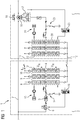
- figure 1 shows a universal power flow controller (UPFC) 1.
- the UPFC 1 comprises a first converter unit 2 and a second converter unit 3.
- the first converter unit 2 has a first converter 4 which is connected via a transformer 5 and a shunt 6 in parallel to a three-phase network line 7.
- the first converter 4 is a so-called modular multilevel converter. It comprises three parallel phase modules, wherein each of the phase modules 8-10, wherein each of the phase modules has two converter arms arranged between a respective AC connection and one of two DC poles 11 or 12. Every converter arm comprises an arm choke and a series of submodules 13, wherein each submodule comprises semiconductor switches and an energy storage, e.g. a capacitor.
- the semiconductor switches and the capacitor of said submodule are e.g.
- the first converter unit 2 comprises a first star point reactor 14, a cooling system 15 and a control arrangement 16 designed to control and/or drive the shunt 6 and the switches of the submodules 13.
- the second converter unit 3 comprises a second converter 20 which is a modular multilevel converter similar to the first converter 4.
- the second converter 20 is on its AC side connected via a fast bypass device 17 and a transformer 18 to the network line 7.
- a bypass switch 19 is provided for bypassing the second converter 20.
- the second converter unit 3 comprises a second star point reactor 21, a cooling system 22 and a control arrangement 23 designed to control the switches of the submodules 13 and the fast bypass device 17.
- the first and the second converter are connected to each other via their respective DC sides forming an intermediate DC link 11, 12.
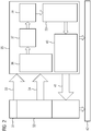
- FIG. 2 shows an example of a method in accordance with the invention.
- the TSO or DSO 31 performs an optimal power flow calculation in block 32 in order to manage an operation planning and the necessary switching procedures.
- As an output of the calculations performed by the TSO/DSO it provides an information 33 about congestion in various lines of the corresponding supply network and an information 34 about underutilized lines in the network to a grid planner 35.
- the grid planner defines in a block 36 target functions and other parameters of planning. It also selects a number of power flow control devices such as UPFC or PST to be used for power flow control in the supply network.
- a model generator in block 37 uses the information provided by block 36 and the information from the TSO/DSO for a model setup using a mixed integer linear programming for modelling the power flow in the network.
- the optimization simulation is run. Given the result of the simulation, in block 39 the solutions are provided concerning the setting and other requirements for the power flow controllers.
- the power flow calculation is run in order to obtain a ranking of locations for the power flow control devices. Preferably a coordinated UPFC operation is taken into account in order to solve the problem of congestions in the network.
- an information 41 about the location and also about the operation methodology is provided to the DSO/TSO 31 where a new and improved power flow calculation can be performed based on the provided information. Additionally, the results are also provided in order to facilitate the setup of requirements of new power flow controllers by their respective manufacturers in block 42.
Landscapes
- Engineering & Computer Science (AREA)
- Power Engineering (AREA)
- Physics & Mathematics (AREA)
- General Physics & Mathematics (AREA)
- Automation & Control Theory (AREA)
- Supply And Distribution Of Alternating Current (AREA)
Abstract
Description
- The invention relates to a method for controlling power flow in an electrical supply network.
- As a result of new environmental legislation, rights-of-way issues, construction cost increases, deregulation policies and decentralized power generation, there is an increasing recognition of the necessity to utilize the existing transmission system assets to the maximum extent possible.
- At the same time high penetration of decentralize renewable generation i.e. wind park based on environment condition, regulation policy of Transmission System Operators (TSO) and Distribution System Operators (DSO) make the operation of transmission system more challenging. In this context, TSOs are facing problems to control the power flow and secure the system efficiently and effectively with existing controller and operation methodology.
- The power transmitted over an AC transmission line is a function of the line impedance, the magnitude of sending-end and receiving-end voltages, and the phase angle between these voltages. Traditional controller in transmission system like phase shifting transformers with mechanical tap-changer and fixed series capacitor are used to control power flow. A new generation of power flow controllers is given by Universal power flow controllers (UPFC) comprising two converters coupled to each other by their respective DC sides and connected to the AC network via their AC sides (known e.g. from the article "Comprehensive Power Flow Analyses and Novel Feedforward Coordination Control Strategy for MMC-based UPFC" by Liu et al., Energies 2019).
- In current situation any grid is divided in different control areas based on certain agreement. Each control area in the grid must achieve balance between power supplied and power consumed. Control areas achieve this balance with the help of power sales and purchase using tie-lines between control areas. These transactions are normally scheduled in advance based on forecast load, the cost and availability of on-line generation and the capacity available on the transmission system. Further, to establish generous stability margins enabling the system to recover from faults, line and generator outages, and equipment failures results in a significant underutilization of the AC transmission system with current slow conventional controllers.
- The object of the invention is to propose an effective and reliable method for controlling power flow in an electrical supply network.
- The object is achieved by a method for controlling power flow in an electrical supply network comprising the steps of providing a power flow control device, providing a model of the supply network for estimating the distribution of the power flow in the supply network in accordance with predefined network parameters, simulating the power flow in the network using said model such that at least on potential congestion path in the supply network is identified, wherein, as a result of the simulation, a positioning scheme for the at least one power flow control device is provided, such that congestion in the identified potential congestion path can be avoided, arranging said at least one power flow device in accordance with said positioning scheme, and controlling power flow in said supply network by means of the at least one power flow control device. The present invention is based on the finding that an optimal placement of the power flow control device in the supply network is very much essential in order to obtain the maximum possible efficiency and reliability for the power flow control. In accordance with the present invention, in order to find the best arrangement for the at least one power flow control device the supply network is simulated using a supply network model. The simulation considers possible placements of the one or more power flow control devices and correspondingly finds at least one potential congestion path or network line. The potential congestion path is given by a network path or line where a congestion is probable to occur under certain network conditions, e.g. in case of a fault or an overload. In this manner the at least one power flow device can be utilized in a most effective and reliable way, when arranged according to the positioning scheme provided by the simulation. The power flow control device can e.g. be placed directly in the potential congestion path but it may be in some cases more efficient to place the power flow control device in a network path which is underutilized in case of congestion in the network, as for example in a transmission line next to the potential congestion path.
- The simulation is preferably carried out taking into consideration the placement of the power flow device within the supply network in order to determine an optimal power flow distribution in the supply network.
- According to an embodiment of the invention the at least power flow control device is an UPFC. The UPFC comprises e.g. a first and a second modular multilevel converter, wherein the converters are connected to each other by their respective dc sides wherein the ac side of each of the converters respectively is connected to a network line (transmission line) of the supply network. The UPFC comprises preferably modular multilevel voltage sourced converters (MMC) with Insulated Gate Bipolar Transistors (IGBT) or other suitable disactivable semiconductor switches (like e.g. IGCT) that are arranged as rectifier at one end and inverter at the other end. Rectifier and inverter are interconnected with a DC link. The converter units are preferably connected to the AC line via shunt connection at one side and via in series connection at the other side. Preferably, transformers at both sides decouple the system with DC link from the AC system and adapt the AC system voltage to required voltage level of the converters. In some applications, the power flow control device can be a Static Synchronous Series Compensator (SSSC) or any other series voltage control device with variable series impedance. The SSSC comprises a voltage source converter coupled with a transformer which is connected in series with a transmission line.
- The power flow control device, in particular a UPFC, can be simulated as an additional voltage vector Vc added to a line voltage Vs. The amplitude of Vc can be varied, the angle of Vc can be set to pi/2 with respect to the resulting vector Vs' = Vs + Vc. In this way, the UPFC is represented as a generalized synchronous voltage source.
- According to another embodiment of the invention the at least one power flow control device is an PST. The PST is simulated as a predefined phase shift of a line voltage Vs, which is a simple and effective representation of the PST in the simulation.
- In further embodiments one or more UPFCs and one or more PSTs are used at the same time, depending on the supply network configuration.
- The simulation is preferably carried out using a Mixed-Integer Linear Programming (MILP) algorithm. In particular the MILP algorithm is employed to solve the optimization problem and to run the power flow calculation in the model network.
- Preferably the model of the supply network is generated in accordance with information on the capacity of network lines of the supply network. The information can be provided directly by the DSO or the TSO and can comprise information about congestion in various lines and/or information about underutilized lines.
- The invention relates further to a data processing arrangement for controlling power flow in an electrical supply network.
- The object of the invention is to propose such a data processing arrangement which allows an effective and reliable control of power flow in the network.
- The object is achieved by a data processing arrangement comprising a model generator for generating a model of the supply network, said model providing a power flow distribution in the supply network in accordance with predefined network parameters, and a simulation module for carrying out a simulation of the power flow in the modelled supply network such that at least on potential congestion path in the supply network is identified.
- The invention is explained below with reference to exemplary embodiment illustrated in the
figures 1 and2 . -
Figure 1 shows a schematic view of a UPFC; -
Figure 2 shows a schematic view of an exemplary embodiment of a method according to the invention. - In detail,
figure 1 shows a universal power flow controller (UPFC) 1. The UPFC 1 comprises afirst converter unit 2 and asecond converter unit 3. Thefirst converter unit 2 has a first converter 4 which is connected via atransformer 5 and ashunt 6 in parallel to a three-phase network line 7. The first converter 4 is a so-called modular multilevel converter. It comprises three parallel phase modules, wherein each of the phase modules 8-10, wherein each of the phase modules has two converter arms arranged between a respective AC connection and one of twoDC poles 11 or 12. Every converter arm comprises an arm choke and a series ofsubmodules 13, wherein each submodule comprises semiconductor switches and an energy storage, e.g. a capacitor. The semiconductor switches and the capacitor of said submodule are e.g. arranged to form a so-called half-bridge circuit, assembled to form a multilevel arrangement. Additionally, thefirst converter unit 2 comprises a firststar point reactor 14, acooling system 15 and acontrol arrangement 16 designed to control and/or drive theshunt 6 and the switches of thesubmodules 13. - The
second converter unit 3 comprises asecond converter 20 which is a modular multilevel converter similar to the first converter 4. Thesecond converter 20 is on its AC side connected via a fast bypass device 17 and atransformer 18 to the network line 7. Abypass switch 19 is provided for bypassing thesecond converter 20. Moreover, thesecond converter unit 3 comprises a second star point reactor 21, acooling system 22 and acontrol arrangement 23 designed to control the switches of thesubmodules 13 and the fast bypass device 17. - The first and the second converter are connected to each other via their respective DC sides forming an
intermediate DC link 11, 12. -
Figure 2 shows an example of a method in accordance with the invention. The TSO or DSO 31 performs an optimal power flow calculation inblock 32 in order to manage an operation planning and the necessary switching procedures. As an output of the calculations performed by the TSO/DSO it provides aninformation 33 about congestion in various lines of the corresponding supply network and aninformation 34 about underutilized lines in the network to a grid planner 35. The grid planner defines in ablock 36 target functions and other parameters of planning. It also selects a number of power flow control devices such as UPFC or PST to be used for power flow control in the supply network. A model generator inblock 37 uses the information provided byblock 36 and the information from the TSO/DSO for a model setup using a mixed integer linear programming for modelling the power flow in the network. Inblock 38 the optimization simulation is run. Given the result of the simulation, inblock 39 the solutions are provided concerning the setting and other requirements for the power flow controllers. Inblock 40 the power flow calculation is run in order to obtain a ranking of locations for the power flow control devices. Preferably a coordinated UPFC operation is taken into account in order to solve the problem of congestions in the network. As an output of the grid planner, aninformation 41 about the location and also about the operation methodology is provided to the DSO/TSO 31 where a new and improved power flow calculation can be performed based on the provided information. Additionally, the results are also provided in order to facilitate the setup of requirements of new power flow controllers by their respective manufacturers inblock 42.
Claims (10)
- Method for controlling power flow in an electrical supply network comprising the steps of- providing at least one power flow control device,- providing a model of the supply network for estimating the distribution of said power flow in said supply network in accordance with predefined network parameters,- simulating the power flow in the network using said model such that at least on potential congestion path in the supply network is identified, wherein, as a result of the simulation, a positioning scheme for the at least one power flow control device is provided, such that congestion in the identified potential congestion path can be avoided,- arranging said at least one power flow device in accordance with said positioning scheme, and- controlling power flow in said supply network by means of said at least one power flow control device.
- Method according to claim 1, wherein the simulation is carried out taking into consideration the placement of the power flow device within the supply network in order to determine an optimal power flow distribution in the supply network.
- Method according to one of the preceding claims, wherein the at least power flow control device is an UPFC or an SSSC or any other series voltage control device with variable series impedance.
- Method according to claim 3, wherein the UPFC comprises a first and a second modular multilevel converter, wherein the converters are connected to each other by their respective dc sides and the ac side of each of the converters is connected to a network line of the supply network.
- Method according to one of the claims 3 or 4, wherein the power flow control device is simulated as an additional voltage vector of a line voltage.
- Method according to one of the preceding claims, wherein the at least one power flow control device is an PST.
- Method according to claim 6, wherein the PST is simulated as a predefined phase shift of a line voltage.
- Method according to one of the preceding claims, wherein the simulation is carried out using a MILP algorithm.
- Method according to one of the preceding claims, wherein the model of the supply network is generated in accordance with information on the capacity of network lines of the supply network.
- Data processing arrangement for controlling power flow in an electrical supply network comprising- a model generator for generating a model of the supply network, said model providing a power flow distribution in the supply network in accordance with predefined network parameters,- a simulation module for carrying out a simulation of the power flow in the modelled supply network such that at least on potential congestion path in the supply network is identified, wherein, as a result of the simulation, a positioning scheme for the at least one power flow control device is provided, such that congestion in the identified potential congestion path can be avoided.
Priority Applications (2)
| Application Number | Priority Date | Filing Date | Title |
|---|---|---|---|
| EP19189593.7A EP3772149A1 (en) | 2019-08-01 | 2019-08-01 | Method for controlling power flow in an electrical supply network |
| US16/944,424 US20210036516A1 (en) | 2019-08-01 | 2020-07-31 | Method and data processing configuraton for controlling power flow in an electrical supply network |
Applications Claiming Priority (1)
| Application Number | Priority Date | Filing Date | Title |
|---|---|---|---|
| EP19189593.7A EP3772149A1 (en) | 2019-08-01 | 2019-08-01 | Method for controlling power flow in an electrical supply network |
Publications (1)
| Publication Number | Publication Date |
|---|---|
| EP3772149A1 true EP3772149A1 (en) | 2021-02-03 |
Family
ID=67539255
Family Applications (1)
| Application Number | Title | Priority Date | Filing Date |
|---|---|---|---|
| EP19189593.7A Pending EP3772149A1 (en) | 2019-08-01 | 2019-08-01 | Method for controlling power flow in an electrical supply network |
Country Status (2)
| Country | Link |
|---|---|
| US (1) | US20210036516A1 (en) |
| EP (1) | EP3772149A1 (en) |
Cited By (1)
| Publication number | Priority date | Publication date | Assignee | Title |
|---|---|---|---|---|
| CN118920213A (en) * | 2024-10-12 | 2024-11-08 | 国网安徽省电力有限公司宣城供电公司 | Connector for distribution network compensation |
Citations (1)
| Publication number | Priority date | Publication date | Assignee | Title |
|---|---|---|---|---|
| US20120022713A1 (en) * | 2010-01-14 | 2012-01-26 | Deaver Sr Brian J | Power Flow Simulation System, Method and Device |
-
2019
- 2019-08-01 EP EP19189593.7A patent/EP3772149A1/en active Pending
-
2020
- 2020-07-31 US US16/944,424 patent/US20210036516A1/en not_active Abandoned
Patent Citations (1)
| Publication number | Priority date | Publication date | Assignee | Title |
|---|---|---|---|---|
| US20120022713A1 (en) * | 2010-01-14 | 2012-01-26 | Deaver Sr Brian J | Power Flow Simulation System, Method and Device |
Non-Patent Citations (5)
| Title |
|---|
| LIU ET AL.: "Comprehensive Power Flow Analyses and Novel Feedfor-ward Coordination Control Strategy for MMC-based UPFC", ENERGIES, 2019 |
| SAUTUA AITOR HERNANDEZ ET AL: "Survey and crossed comparison of types, optimal location techniques, and power system applications of FACTS", 2013 IEEE GRENOBLE CONFERENCE, IEEE, 16 June 2013 (2013-06-16), pages 1 - 6, XP032519953, DOI: 10.1109/PTC.2013.6652451 * |
| SHRAWANE KAPSE SHILPA SUBHASH ET AL: "Improvement of ORPD Algorithm for Transmission Loss Minimization and Voltage Control Using UPFC by HGAPSO Approach", JOURNAL OF THE INSTITUTION OF ENGINEERS (INDIA): SERIES B, SPRINGER INDIA, INDIA, vol. 99, no. 6, 14 July 2018 (2018-07-14), pages 575 - 585, XP036627790, ISSN: 2250-2106, [retrieved on 20180714], DOI: 10.1007/S40031-018-0349-1 * |
| SINGH S N ET AL: "Locating Unified Power Flow Controller for Enhancing Power System Loadability", FUTURE POWER SYSTEMS, 2005 INTERNATIONAL CONFERENCE ON AMSTERDAM, THE NETHERLANDS 16-18 NOV. 2005, PISCATAWAY, NJ, USA,IEEE, 16 November 2005 (2005-11-16), pages 1 - 5, XP010897580, ISBN: 978-90-78205-02-9 * |
| XIAOHU ZHANG ET AL: "Optimal Allocation of Series FACTS Devices in Large Scale Systems", ARXIV.ORG, CORNELL UNIVERSITY LIBRARY, 201 OLIN LIBRARY CORNELL UNIVERSITY ITHACA, NY 14853, 9 January 2018 (2018-01-09), XP081205277, DOI: 10.1049/IET-GTD.2017.1223 * |
Cited By (1)
| Publication number | Priority date | Publication date | Assignee | Title |
|---|---|---|---|---|
| CN118920213A (en) * | 2024-10-12 | 2024-11-08 | 国网安徽省电力有限公司宣城供电公司 | Connector for distribution network compensation |
Also Published As
| Publication number | Publication date |
|---|---|
| US20210036516A1 (en) | 2021-02-04 |
Similar Documents
| Publication | Publication Date | Title |
|---|---|---|
| Fuad et al. | Soft open point in distribution networks | |
| Rivera et al. | Bipolar DC power conversion: State-of-the-art and emerging technologies | |
| Engel et al. | Comparison of the modular multilevel DC converter and the dual-active bridge converter for power conversion in HVDC and MVDC grids | |
| Kawakami et al. | Development of a 500-kW modular multilevel cascade converter for battery energy storage systems | |
| Vandoorn et al. | Voltage-based control of a smart transformer in a microgrid | |
| Wickramasinghe et al. | Alternate arm converters-based HVDC model compatible with the CIGRE B4 DC grid test system | |
| US8866338B2 (en) | Method and apparatus for improving power generation in a thermal power plant | |
| Majumder | Aggregation of microgrids with DC system | |
| US9209679B2 (en) | Method and apparatus for transferring power between AC and DC power systems | |
| JP2013048546A (en) | Power conversion system and method | |
| WO2019053447A1 (en) | Sub-station transformer load balancing system | |
| Feldman et al. | DC fault ride-through capability and STATCOM operation of a hybrid voltage source converter arrangement for HVDC power transmission and reactive power compensation | |
| EP3301775A1 (en) | A power converter system for power quality compensation and load balancing connected to an electric power distribution grid | |
| Grainger et al. | Analysis of an offshore medium voltage DC microgrid environment—Part I: Power sharing controller design | |
| KR101659252B1 (en) | Modular multi-level converter and controlling method thereof | |
| Zhou | Co-ordination of converter controls and an analysis of converter operating limits in VSC-HVdc grids | |
| EP3772149A1 (en) | Method for controlling power flow in an electrical supply network | |
| Andrews et al. | Decarbonizing turbine powered oil and gas processes with electrical adjustable speed drive systems | |
| Paulinder | Operation and control of HVDC links embedded in AC systems | |
| Farasat et al. | A novel control principle for all-electric ship power systems | |
| Babu et al. | Modular multilevel converter for enhanced offshore windfarm integration to medium voltage DC microgrid | |
| Moufid et al. | Distribution network reconfiguration for power loss minimization using soft open point | |
| KR101678802B1 (en) | Modular multi-level converter and controlling method thereof | |
| RU195453U1 (en) | MULTILEVEL DEVICE FOR COMPENSATION OF REACTIVE POWER AND SUPPRESSION OF HIGH HARMONIC CURRENT | |
| Cervero et al. | A Modular Solid-State Transformer for 3 kV DC Grids: Design, Topology, and Performance Evaluation |
Legal Events
| Date | Code | Title | Description |
|---|---|---|---|
| PUAI | Public reference made under article 153(3) epc to a published international application that has entered the european phase |
Free format text: ORIGINAL CODE: 0009012 |
|
| STAA | Information on the status of an ep patent application or granted ep patent |
Free format text: STATUS: THE APPLICATION HAS BEEN PUBLISHED |
|
| AK | Designated contracting states |
Kind code of ref document: A1 Designated state(s): AL AT BE BG CH CY CZ DE DK EE ES FI FR GB GR HR HU IE IS IT LI LT LU LV MC MK MT NL NO PL PT RO RS SE SI SK SM TR |
|
| AX | Request for extension of the european patent |
Extension state: BA ME |
|
| STAA | Information on the status of an ep patent application or granted ep patent |
Free format text: STATUS: REQUEST FOR EXAMINATION WAS MADE |
|
| 17P | Request for examination filed |
Effective date: 20210604 |
|
| RBV | Designated contracting states (corrected) |
Designated state(s): AL AT BE BG CH CY CZ DE DK EE ES FI FR GB GR HR HU IE IS IT LI LT LU LV MC MK MT NL NO PL PT RO RS SE SI SK SM TR |
|
| STAA | Information on the status of an ep patent application or granted ep patent |
Free format text: STATUS: EXAMINATION IS IN PROGRESS |
|
| 17Q | First examination report despatched |
Effective date: 20241217 |