EP3772068A1 - Twist resistant electrical harness - Google Patents
Twist resistant electrical harness Download PDFInfo
- Publication number
- EP3772068A1 EP3772068A1 EP19214716.3A EP19214716A EP3772068A1 EP 3772068 A1 EP3772068 A1 EP 3772068A1 EP 19214716 A EP19214716 A EP 19214716A EP 3772068 A1 EP3772068 A1 EP 3772068A1
- Authority
- EP
- European Patent Office
- Prior art keywords
- tubing
- electrical
- electrical harness
- harness
- braid
- Prior art date
- Legal status (The legal status is an assumption and is not a legal conclusion. Google has not performed a legal analysis and makes no representation as to the accuracy of the status listed.)
- Pending
Links
- 239000002861 polymer material Substances 0.000 claims description 7
- 230000004044 response Effects 0.000 claims description 6
- 230000001419 dependent effect Effects 0.000 claims 1
- 238000000034 method Methods 0.000 description 7
- 230000008901 benefit Effects 0.000 description 6
- 229920000642 polymer Polymers 0.000 description 5
- 238000005452 bending Methods 0.000 description 3
- 238000004519 manufacturing process Methods 0.000 description 3
- 238000001125 extrusion Methods 0.000 description 2
- 239000007769 metal material Substances 0.000 description 2
- 230000004048 modification Effects 0.000 description 2
- 238000012986 modification Methods 0.000 description 2
- 230000008569 process Effects 0.000 description 2
- 230000008878 coupling Effects 0.000 description 1
- 238000010168 coupling process Methods 0.000 description 1
- 238000005859 coupling reaction Methods 0.000 description 1
- 239000000835 fiber Substances 0.000 description 1
- 239000000463 material Substances 0.000 description 1
- 239000002184 metal Substances 0.000 description 1
- 229920002635 polyurethane Polymers 0.000 description 1
- 239000004814 polyurethane Substances 0.000 description 1
- 229910001220 stainless steel Inorganic materials 0.000 description 1
- 239000010935 stainless steel Substances 0.000 description 1
- 229920001169 thermoplastic Polymers 0.000 description 1
- 229920001187 thermosetting polymer Polymers 0.000 description 1
Images

Classifications
-
- H—ELECTRICITY
- H01—ELECTRIC ELEMENTS
- H01B—CABLES; CONDUCTORS; INSULATORS; SELECTION OF MATERIALS FOR THEIR CONDUCTIVE, INSULATING OR DIELECTRIC PROPERTIES
- H01B7/00—Insulated conductors or cables characterised by their form
- H01B7/04—Flexible cables, conductors, or cords, e.g. trailing cables
- H01B7/041—Flexible cables, conductors, or cords, e.g. trailing cables attached to mobile objects, e.g. portable tools, elevators, mining equipment, hoisting cables
-
- H—ELECTRICITY
- H01—ELECTRIC ELEMENTS
- H01B—CABLES; CONDUCTORS; INSULATORS; SELECTION OF MATERIALS FOR THEIR CONDUCTIVE, INSULATING OR DIELECTRIC PROPERTIES
- H01B7/00—Insulated conductors or cables characterised by their form
- H01B7/17—Protection against damage caused by external factors, e.g. sheaths or armouring
- H01B7/18—Protection against damage caused by wear, mechanical force or pressure; Sheaths; Armouring
- H01B7/1865—Sheaths comprising braided non-metallic layers
-
- H—ELECTRICITY
- H01—ELECTRIC ELEMENTS
- H01B—CABLES; CONDUCTORS; INSULATORS; SELECTION OF MATERIALS FOR THEIR CONDUCTIVE, INSULATING OR DIELECTRIC PROPERTIES
- H01B7/00—Insulated conductors or cables characterised by their form
- H01B7/17—Protection against damage caused by external factors, e.g. sheaths or armouring
- H01B7/18—Protection against damage caused by wear, mechanical force or pressure; Sheaths; Armouring
- H01B7/1875—Multi-layer sheaths
- H01B7/188—Inter-layer adherence promoting means
-
- H—ELECTRICITY
- H01—ELECTRIC ELEMENTS
- H01B—CABLES; CONDUCTORS; INSULATORS; SELECTION OF MATERIALS FOR THEIR CONDUCTIVE, INSULATING OR DIELECTRIC PROPERTIES
- H01B7/00—Insulated conductors or cables characterised by their form
- H01B7/17—Protection against damage caused by external factors, e.g. sheaths or armouring
- H01B7/18—Protection against damage caused by wear, mechanical force or pressure; Sheaths; Armouring
- H01B7/22—Metal wires or tapes, e.g. made of steel
- H01B7/228—Metal braid
-
- H—ELECTRICITY
- H02—GENERATION; CONVERSION OR DISTRIBUTION OF ELECTRIC POWER
- H02G—INSTALLATION OF ELECTRIC CABLES OR LINES, OR OF COMBINED OPTICAL AND ELECTRIC CABLES OR LINES
- H02G3/00—Installations of electric cables or lines or protective tubing therefor in or on buildings, equivalent structures or vehicles
- H02G3/02—Details
- H02G3/04—Protective tubing or conduits, e.g. cable ladders or cable troughs
- H02G3/0462—Tubings, i.e. having a closed section
- H02G3/0481—Tubings, i.e. having a closed section with a circular cross-section
-
- H—ELECTRICITY
- H02—GENERATION; CONVERSION OR DISTRIBUTION OF ELECTRIC POWER
- H02G—INSTALLATION OF ELECTRIC CABLES OR LINES, OR OF COMBINED OPTICAL AND ELECTRIC CABLES OR LINES
- H02G11/00—Arrangements of electric cables or lines between relatively-movable parts
Definitions
- the present disclosure relates generally to electrical harnesses and, more particularly, to electrical harnesses for routing electric power and/or data between moving parts, or to an electrical harness moving within a single plane of confined space.
- Power cables may move and/or be routed between moving parts, often within a confined space, to provide electric power to various components.
- the power cable may be susceptible to twisting in response to a first member moving with respect to a second member to which the power cable is coupled at either end. This twisting may cause the power cable to bend and come into contact with adjacent parts.
- An electrical harness comprising an electrical cable, an inner tubing extending from a first end of the electrical harness to a second end of the electrical harness, the inner tubing encasing the electrical cable, a braid tubing extending from the first end of the electrical harness to the second end of the electrical harness, the braid tubing encasing the inner tubing, and an outer tubing extending from the first end of the electrical harness to the second end of the electrical harness, the outer tubing encasing the braid tubing, wherein the braid tubing physically contacts the inner tubing and the outer tubing.
- the braid tubing comprises a plurality of wires tightly braided together to form a generally cylindrical tubing.
- the braid tubing is mechanically locked with the inner tubing and the outer tubing.
- the inner tubing encases a plurality of electrical wires.
- the inner tubing comprises a polymer material.
- the outer tubing comprises a polymer material.
- the electrical harness further comprises a first electrical plug positioned at the first end of the electrical harness and a second electrical plug positioned at the second end of the electrical harness.
- the first electrical plug is disposed about the outer tubing.
- an outer diameter of the braid tubing is substantially equal to an inner diameter of the outer tubing.
- an inner diameter of the braid tubing is substantially equal to an outer diameter of the inner tubing.
- a harness system comprising a first component, a second component configured to move with respect to the first component, and an electrical harness.
- the electrical harness comprises an electrical cable having a first end and a second end, an inner tubing extending from the first end of the electrical harness to the second end of the electrical harness, the inner tubing encasing the electrical cable, a braid tubing extending from the first end of the electrical harness to the second end of the electrical harness, the braid tubing encasing the inner tubing, and an outer tubing extending from the first end of the electrical harness to the second end of the electrical harness, the outer tubing encasing the braid tubing, wherein the braid tubing is physically contacting the inner tubing and the outer tubing, and the braid tubing is configured to prevent out of plane movement of the electrical cable in response to the second component moving with respect to the first component.
- the braid tubing comprises a plurality of wires tightly braided together to form a generally cylindrical tubing.
- the braid tubing is mechanically locked with the inner tubing and the outer tubing.
- the inner tubing encases a plurality of electrical wires.
- the inner tubing comprises a polymer material
- the outer tubing comprises the polymer material
- the power drive unit further comprises a first electrical plug positioned at the first end of the electrical harness and a second electrical plug positioned at the second end of the electrical harness, the first electrical plug is disposed about the outer tubing.
- the first electrical plug is cured to the outer tubing.
- an outer diameter of the braid tubing is substantially equal to an inner diameter of the outer tubing, and an inner diameter of the braid tubing is substantially equal to an outer diameter of the inner tubing.
- An electrical harness system comprising a first member, a second member, the second member moveable with respect to the first member, and an electrical harness, comprising an electrical cable extending from the first member to the second member, an inner tubing extending from a first end of the electrical harness to a second end of the electrical harness, the inner tubing encasing the electrical cable, a braid tubing extending from the first end of the electrical harness to the second end of the electrical harness, the braid tubing encasing the inner tubing, and an outer tubing extending from the first end of the electrical harness to the second end of the electrical harness, the outer tubing encasing the braid tubing, wherein the braid tubing is physically contacting the inner tubing and the outer tubing.
- the braid tubing resists twisting in response to the first member moving with respect to the second member.
- references to "a,” “an” or “the” may include one or more than one and that reference to an item in the singular may also include the item in the plural. Further, all ranges may include upper and lower values and all ranges and ratio limits disclosed herein may be combined.
- Electrical harness 100 may include an electrical cable 112 comprising a plurality of wires 102 disposed within a twist resistant electrical harness 104 comprising an outer tubing 106, an inner tubing 108, and a braid tubing 110 disposed between the inner tubing 108 and the outer tubing 106.
- the outer tubing 106 and the inner tubing 108 are made from a polymer material, including thermosetting and/or thermoplastic polymers, such as a polyurethane, among others.
- the braid tubing 110 comprises a wire braided tube or sleeve made from a metallic material, such as stainless steel, among others.
- the braid tubing 110 comprises a wire braided tube or sleeve made from metal-coated fibers. In various embodiments, the braid tubing 110 comprises a braided tube or sleeve made from a non-metallic material. With momentary reference to FIG. 2 , the braid tubing 110 includes wires tightly braided together to form a generally cylindrical tubing. Furthermore, inner tubing 108 and the outer tubing 106 generally conform to the cylindrical shape of braid tubing 110. With respect to FIG. 2 , elements with like element numbering, as depicted in FIG.1 , are intended to be the same and will not necessarily be repeated for the sake of clarity.
- inner tubing 108 may be disposed about electrical cable 112.
- Inner tubing 108 may encase electrical cable 112.
- inner tubing 108 encases plurality of wires 102 of the electrical cable 112.
- Inner tubing 108 may be formed over the plurality of wires 102 via a polymer extrusion manufacturing process in which a polymer is melted and formed in a continuous profile along the length of electrical harness 100.
- Braid tubing 110 may be disposed about inner tubing 108. Braid tubing 110 may encase inner tubing 108.
- the inner diameter D1 of braid tubing 110 may be substantially equal to the outer diameter D2 of inner tubing 108.
- the inner diameter surface of braid tubing 110 may be in contact with the outer diameter surface of inner tubing 108.
- Outer tubing 106 may be disposed about braid tubing 110.
- Outer tubing 106 may encase braid tubing 110.
- Outer tubing 106 may be formed over braid tubing 110 via a polymer extrusion manufacturing process in which a polymer is melted and formed in a continuous profile along the length of electrical harness 100.
- the outer diameter D3 of braid tubing 110 may be substantially equal to the inner diameter D4 of outer tubing 106.
- the outer diameter surface of braid tubing 110 may be in contact with the inner diameter surface of outer tubing 106.
- braid tubing 110 is compressed between outer tubing 106 and inner tubing 108. Due to the relatively soft, elastic nature of the outer tubing 106 and inner tubing 108, the braid tubing 110 may embed into the outer tubing 106 and inner tubing 108, thereby mechanically locking with the outer tubing 106 and inner tubing 108 which prevents the braid tubing 110 from slipping against the outer tubing 106 and inner tubing 108. Thus, the braid tubing 110 is in physical contact with the outer tubing 106 and inner tubing 108. In this manner, the outer tubing 106 and inner tubing 108 compresses the braid tubing 110 such that the braid tubing 110 maintains a common diameter along the length of electrical harness 100, which minimizes twisting of electrical harness 100.
- an electrical harness system may include a first member (e.g., a first component 336 described in FIG. 3 ), a second member (e.g., a second component 338 described in FIG. 3 ) moveable with respect to the first member, and the electrical harness 100 extending therebetween.
- a first member e.g., a first component 336 described in FIG. 3
- a second member e.g., a second component 338 described in FIG. 3
- Inner tubing 108 may extend from a first end (e.g., first end 301 of FIG. 3 ) of the electrical harness 100 to a second end (e.g., second end 302 of FIG. 3 ) of the electrical harness 100.
- Braid tubing 110 may extend from a first end (e.g., first end 301 of FIG. 3 ) of the electrical harness 100 to a second end (e.g., second end 302 of FIG. 3 ) of the electrical harness 100.
- Outer tubing 106 may extend from a first end (e.g., first end 301 of FIG. 3 ) of the electrical harness 100 to a second end (e.g., second end 302 of FIG. 3 ) of the electrical harness 100.
- One such application of an electrical harness may be for a system with a first component that moves relative to a second component, with a first end of the electrical harness coupled to the first component and a second, opposite end of the electrical harness coupled to the second component, where it is desired to control the planes of movement of the dynamic electrical harness.
- the harness system 350 includes a first electrical plug 352, configured to attach to the first component 336 via a first electrical receptacle 353.
- the first electrical plug 352 may receive various power inputs from a power supply and control module that are configured to power an electronic component.
- the harness system 350 also includes a second electrical plug 354, configured to attach to a second component 338, via a second electrical receptacle 355.
- the second electrical plug 354 may receive the power inputs from the first electrical plug 352 and conveys them to one or more electronics associated with second component 338.
- An electrical harness 356 connects the first electrical plug 352 to the second electrical plug 354.
- Electrical harness 356 may be similar to electrical harness 100 of FIG. 1 and FIG. 2 .
- First electrical plug 352 may be coupled to a first end 301 of the electrical harness 356.
- Second electrical plug 354 may be coupled to a second end 302 of the electrical harness 356.
- first electrical plug 352 is coupled to an outer tubing 306 of electrical harness 356.
- Outer tubing 306 may be similar to outer tubing 106 of FIG. 1 and FIG. 2 .
- second electrical plug 354 is coupled to the outer tubing 306 of electrical harness 356.
- First electrical plug 352 and second electrical plug 354 may be coupled to outer tubing 306 using an overmolding manufacturing process wherein a melted polymer is injected in a mold tool surrounding a portion of the outer tubing 306 and cured to the outer tubing 306. In this regard, loads may be transferred between first electrical plug 352 and second electrical plug 354, via braid tubing 110 (see FIG. 1 ) and outer tubing 306.
- first electrical plug 352 relative to second electrical plug 354 may be maintained via the braid tubing 110 (see FIG. 1 ) of electrical harness 356.
- braid tubing 110 may react to torque applied to electrical harness 356, preventing twisting of electrical harness 356.
- electrical harness 356 may bend about an axis 391 as second component 338 moves with respect to first component 336 without bending, deflecting, or otherwise moving in a direction parallel to axis 391.
- electrical harness 356 may be restricted to movement primarily within a single plane, such as plane 390.
- electrical harness 356 may be manufactured with first electrical plug 352 and second electrical plug 354 preformed to a desired orientation with respect to each other to prevent a technician from misaligning or incorrectly installing the electrical harness 356 due to the braid tubing 110 (see FIG. 1 ) being resistant to twisting of electrical harness 356.
- harness system 350 With combined reference to FIG. 4A and FIG. 4B , a top view of harness system 350 is illustrated. As second component 338 moves, the harness system 350 will remain primarily in the same plane, e.g., plane 390 if second component 338 is rotating about axis 391.
- FIG. 4A illustrates second component 338 at a first position with respect to first component 336
- FIG. 4B illustrates second component 338 rotated about axis 391 to a second position with respect to first component 336.
- Electrical harness 356 may be restricted to movement within plane 390 as second component 338 moves between the first position and the second position. That is, the braid tubing 110 (see FIG.
- references to "one embodiment”, “an embodiment”, “various embodiments”, etc. indicate that the embodiment described may include a particular feature, structure, or characteristic, but every embodiment may not necessarily include the particular feature, structure, or characteristic. Moreover, such phrases are not necessarily referring to the same embodiment. Further, when a particular feature, structure, or characteristic is described in connection with an embodiment, it is submitted that it is within the knowledge of one skilled in the art to affect such feature, structure, or characteristic in connection with other embodiments whether or not explicitly described. After reading the description, it will be apparent to one skilled in the relevant art(s) how to implement the disclosure in alternative embodiments.
Landscapes
- Engineering & Computer Science (AREA)
- Architecture (AREA)
- Civil Engineering (AREA)
- Structural Engineering (AREA)
- Details Of Indoor Wiring (AREA)
- Insulated Conductors (AREA)
Abstract
Description
- The present disclosure relates generally to electrical harnesses and, more particularly, to electrical harnesses for routing electric power and/or data between moving parts, or to an electrical harness moving within a single plane of confined space.
- Power cables may move and/or be routed between moving parts, often within a confined space, to provide electric power to various components. The power cable may be susceptible to twisting in response to a first member moving with respect to a second member to which the power cable is coupled at either end. This twisting may cause the power cable to bend and come into contact with adjacent parts.
- An electrical harness is disclosed, comprising an electrical cable, an inner tubing extending from a first end of the electrical harness to a second end of the electrical harness, the inner tubing encasing the electrical cable, a braid tubing extending from the first end of the electrical harness to the second end of the electrical harness, the braid tubing encasing the inner tubing, and an outer tubing extending from the first end of the electrical harness to the second end of the electrical harness, the outer tubing encasing the braid tubing, wherein the braid tubing physically contacts the inner tubing and the outer tubing.
- In various embodiments, the braid tubing comprises a plurality of wires tightly braided together to form a generally cylindrical tubing.
- In various embodiments, the braid tubing is mechanically locked with the inner tubing and the outer tubing.
- In various embodiments, the inner tubing encases a plurality of electrical wires.
- In various embodiments, the inner tubing comprises a polymer material.
- In various embodiments, the outer tubing comprises a polymer material.
- In various embodiments, the electrical harness further comprises a first electrical plug positioned at the first end of the electrical harness and a second electrical plug positioned at the second end of the electrical harness.
- In various embodiments, the first electrical plug is disposed about the outer tubing.
- In various embodiments, an outer diameter of the braid tubing is substantially equal to an inner diameter of the outer tubing.
- In various embodiments, an inner diameter of the braid tubing is substantially equal to an outer diameter of the inner tubing.
- A harness system is disclosed, comprising a first component, a second component configured to move with respect to the first component, and an electrical harness. The electrical harness comprises an electrical cable having a first end and a second end, an inner tubing extending from the first end of the electrical harness to the second end of the electrical harness, the inner tubing encasing the electrical cable, a braid tubing extending from the first end of the electrical harness to the second end of the electrical harness, the braid tubing encasing the inner tubing, and an outer tubing extending from the first end of the electrical harness to the second end of the electrical harness, the outer tubing encasing the braid tubing, wherein the braid tubing is physically contacting the inner tubing and the outer tubing, and the braid tubing is configured to prevent out of plane movement of the electrical cable in response to the second component moving with respect to the first component.
- In various embodiments, the braid tubing comprises a plurality of wires tightly braided together to form a generally cylindrical tubing.
- In various embodiments, the braid tubing is mechanically locked with the inner tubing and the outer tubing.
- In various embodiments, the inner tubing encases a plurality of electrical wires.
- In various embodiments, the inner tubing comprises a polymer material, and the outer tubing comprises the polymer material.
- In various embodiments, the power drive unit further comprises a first electrical plug positioned at the first end of the electrical harness and a second electrical plug positioned at the second end of the electrical harness, the first electrical plug is disposed about the outer tubing.
- In various embodiments, the first electrical plug is cured to the outer tubing.
- In various embodiments, an outer diameter of the braid tubing is substantially equal to an inner diameter of the outer tubing, and an inner diameter of the braid tubing is substantially equal to an outer diameter of the inner tubing.
- An electrical harness system is disclosed, comprising a first member, a second member, the second member moveable with respect to the first member, and an electrical harness, comprising an electrical cable extending from the first member to the second member, an inner tubing extending from a first end of the electrical harness to a second end of the electrical harness, the inner tubing encasing the electrical cable, a braid tubing extending from the first end of the electrical harness to the second end of the electrical harness, the braid tubing encasing the inner tubing, and an outer tubing extending from the first end of the electrical harness to the second end of the electrical harness, the outer tubing encasing the braid tubing, wherein the braid tubing is physically contacting the inner tubing and the outer tubing.
- In various embodiments, the braid tubing resists twisting in response to the first member moving with respect to the second member.
- The foregoing features and elements may be combined in various combinations without exclusivity, unless expressly indicated otherwise. These features and elements as well as the operation thereof will become more apparent in light of the following description and the accompanying drawings. It should be understood, however, the following description and drawings are intended to be exemplary in nature and nonlimiting.
- The subject matter of the present disclosure is particularly pointed out and distinctly claimed in the concluding portion of the specification. A more complete understanding of the present disclosure, however, may best be obtained by referring to the following detailed description and claims in connection with the following drawings. While the drawings illustrate various embodiments employing the principles described herein, the drawings do not limit the scope of the claims.
-
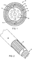
FIG. 1 is a cross-section view of an electrical harness, in accordance with various embodiments; -
FIG. 2 is a partial cutaway view of an electrical harness, in accordance with various embodiments; -
FIG. 3 is a schematic perspective view of a harness system having an electrical harness, in accordance with various embodiments; and -
FIGS. 4A and 4B are schematic overhead views of a harness system, showing an electrical harness in different orientations, in accordance with various embodiments. - The following detailed description of various embodiments herein makes reference to the accompanying drawings, which show various embodiments by way of illustration. While these various embodiments are described in sufficient detail to enable those skilled in the art to practice the disclosure, it should be understood that other embodiments may be realized and that changes may be made without departing from the scope of the disclosure. Thus, the detailed description herein is presented for purposes of illustration only and not of limitation. Furthermore, any reference to singular includes plural embodiments, and any reference to more than one component or step may include a singular embodiment or step. Also, any reference to attached, fixed, connected, or the like may include permanent, removable, temporary, partial, full or any other possible attachment option. Additionally, any reference to without contact (or similar phrases) may also include reduced contact or minimal contact. It should also be understood that unless specifically stated otherwise, references to "a," "an" or "the" may include one or more than one and that reference to an item in the singular may also include the item in the plural. Further, all ranges may include upper and lower values and all ranges and ratio limits disclosed herein may be combined.
- With reference to
FIG. 1 , a cross-section view of anelectrical harness 100 is illustrated, in accordance with various embodiments.Electrical harness 100 may include anelectrical cable 112 comprising a plurality ofwires 102 disposed within a twist resistantelectrical harness 104 comprising anouter tubing 106, aninner tubing 108, and abraid tubing 110 disposed between theinner tubing 108 and theouter tubing 106. In various embodiments, theouter tubing 106 and theinner tubing 108 are made from a polymer material, including thermosetting and/or thermoplastic polymers, such as a polyurethane, among others. In various embodiments, thebraid tubing 110 comprises a wire braided tube or sleeve made from a metallic material, such as stainless steel, among others. In various embodiments, thebraid tubing 110 comprises a wire braided tube or sleeve made from metal-coated fibers. In various embodiments, thebraid tubing 110 comprises a braided tube or sleeve made from a non-metallic material. With momentary reference toFIG. 2 , thebraid tubing 110 includes wires tightly braided together to form a generally cylindrical tubing. Furthermore,inner tubing 108 and theouter tubing 106 generally conform to the cylindrical shape ofbraid tubing 110. With respect toFIG. 2 , elements with like element numbering, as depicted inFIG.1 , are intended to be the same and will not necessarily be repeated for the sake of clarity. - In various embodiments, and with reference to
FIG. 1 ,inner tubing 108 may be disposed aboutelectrical cable 112.Inner tubing 108 may encaseelectrical cable 112. In various embodiments,inner tubing 108 encases plurality ofwires 102 of theelectrical cable 112.Inner tubing 108 may be formed over the plurality ofwires 102 via a polymer extrusion manufacturing process in which a polymer is melted and formed in a continuous profile along the length ofelectrical harness 100.Braid tubing 110 may be disposed aboutinner tubing 108. Braidtubing 110 may encaseinner tubing 108. The inner diameter D1 ofbraid tubing 110 may be substantially equal to the outer diameter D2 ofinner tubing 108. In this regard, the inner diameter surface ofbraid tubing 110 may be in contact with the outer diameter surface ofinner tubing 108.Outer tubing 106 may be disposed aboutbraid tubing 110.Outer tubing 106 may encasebraid tubing 110.Outer tubing 106 may be formed overbraid tubing 110 via a polymer extrusion manufacturing process in which a polymer is melted and formed in a continuous profile along the length ofelectrical harness 100. The outer diameter D3 ofbraid tubing 110 may be substantially equal to the inner diameter D4 ofouter tubing 106. In this regard, the outer diameter surface ofbraid tubing 110 may be in contact with the inner diameter surface ofouter tubing 106. - In various embodiments,
braid tubing 110 is compressed betweenouter tubing 106 andinner tubing 108. Due to the relatively soft, elastic nature of theouter tubing 106 andinner tubing 108, thebraid tubing 110 may embed into theouter tubing 106 andinner tubing 108, thereby mechanically locking with theouter tubing 106 andinner tubing 108 which prevents thebraid tubing 110 from slipping against theouter tubing 106 andinner tubing 108. Thus, thebraid tubing 110 is in physical contact with theouter tubing 106 andinner tubing 108. In this manner, theouter tubing 106 andinner tubing 108 compresses thebraid tubing 110 such that thebraid tubing 110 maintains a common diameter along the length ofelectrical harness 100, which minimizes twisting ofelectrical harness 100. Stated differently, thebraid tubing 110 is prevented from twisting, due to the braided wires being mechanically locked with theouter tubing 106 andinner tubing 108, while allowing in-plane bending ofelectrical harness 100, such as during relative movement of two members to which opposite ends ofelectrical harness 100 is connected. In this regard, an electrical harness system may include a first member (e.g., afirst component 336 described inFIG. 3 ), a second member (e.g., asecond component 338 described inFIG. 3 ) moveable with respect to the first member, and theelectrical harness 100 extending therebetween. -
Inner tubing 108, may extend from a first end (e.g.,first end 301 ofFIG. 3 ) of theelectrical harness 100 to a second end (e.g.,second end 302 ofFIG. 3 ) of theelectrical harness 100.Braid tubing 110 may extend from a first end (e.g.,first end 301 ofFIG. 3 ) of theelectrical harness 100 to a second end (e.g.,second end 302 ofFIG. 3 ) of theelectrical harness 100.Outer tubing 106 may extend from a first end (e.g.,first end 301 ofFIG. 3 ) of theelectrical harness 100 to a second end (e.g.,second end 302 ofFIG. 3 ) of theelectrical harness 100. - One such application of an electrical harness may be for a system with a first component that moves relative to a second component, with a first end of the electrical harness coupled to the first component and a second, opposite end of the electrical harness coupled to the second component, where it is desired to control the planes of movement of the dynamic electrical harness.
- Referring now to
FIG. 3 , aharness system 350 is illustrated within thefirst component 336. In various embodiments, theharness system 350 includes a firstelectrical plug 352, configured to attach to thefirst component 336 via a firstelectrical receptacle 353. The firstelectrical plug 352 may receive various power inputs from a power supply and control module that are configured to power an electronic component. In various embodiments, theharness system 350 also includes a secondelectrical plug 354, configured to attach to asecond component 338, via a secondelectrical receptacle 355. The secondelectrical plug 354 may receive the power inputs from the firstelectrical plug 352 and conveys them to one or more electronics associated withsecond component 338. Anelectrical harness 356 connects the firstelectrical plug 352 to the secondelectrical plug 354.Electrical harness 356 may be similar toelectrical harness 100 ofFIG. 1 and FIG. 2 . Firstelectrical plug 352 may be coupled to afirst end 301 of theelectrical harness 356. Secondelectrical plug 354 may be coupled to asecond end 302 of theelectrical harness 356. - In various embodiments, first
electrical plug 352 is coupled to anouter tubing 306 ofelectrical harness 356.Outer tubing 306 may be similar toouter tubing 106 ofFIG. 1 and FIG. 2 . In various embodiments, secondelectrical plug 354 is coupled to theouter tubing 306 ofelectrical harness 356. Firstelectrical plug 352 and secondelectrical plug 354 may be coupled toouter tubing 306 using an overmolding manufacturing process wherein a melted polymer is injected in a mold tool surrounding a portion of theouter tubing 306 and cured to theouter tubing 306. In this regard, loads may be transferred between firstelectrical plug 352 and secondelectrical plug 354, via braid tubing 110 (seeFIG. 1 ) andouter tubing 306. Furthermore, the orientation of firstelectrical plug 352 relative to secondelectrical plug 354 may be maintained via the braid tubing 110 (seeFIG. 1 ) ofelectrical harness 356. Stated differently, braid tubing 110 (seeFIG. 1 ) may react to torque applied toelectrical harness 356, preventing twisting ofelectrical harness 356. For example,electrical harness 356 may bend about anaxis 391 assecond component 338 moves with respect tofirst component 336 without bending, deflecting, or otherwise moving in a direction parallel toaxis 391. Stated differently, assecond component 338 moves with respect to first component 336 (e.g.,second component 338 may rotate about axis 391),electrical harness 356 may be restricted to movement primarily within a single plane, such asplane 390. Furthermore,electrical harness 356 may be manufactured with firstelectrical plug 352 and secondelectrical plug 354 preformed to a desired orientation with respect to each other to prevent a technician from misaligning or incorrectly installing theelectrical harness 356 due to the braid tubing 110 (seeFIG. 1 ) being resistant to twisting ofelectrical harness 356. - With combined reference to
FIG. 4A and FIG. 4B , a top view ofharness system 350 is illustrated. Assecond component 338 moves, theharness system 350 will remain primarily in the same plane, e.g.,plane 390 ifsecond component 338 is rotating aboutaxis 391. For example,FIG. 4A illustratessecond component 338 at a first position with respect tofirst component 336 andFIG. 4B illustratessecond component 338 rotated aboutaxis 391 to a second position with respect tofirst component 336.Electrical harness 356 may be restricted to movement withinplane 390 assecond component 338 moves between the first position and the second position. That is, the braid tubing 110 (seeFIG. 1 ) is configured to prevent out-of-plane bending (i.e., movement perpendicular to plane 391) of theelectrical harness 356 in response to thesecond component 338 moving with respect to thefirst component 354. Any power cables being carried within theharness system 350 are constrained from being caught within moving or rotating components of the system and from inadvertent grounding against conductive components of the system. - Finally, it should be understood that any of the above described concepts can be used alone or in combination with any or all of the other above described concepts. Although various embodiments have been disclosed and described, one of ordinary skill in this art would recognize that certain modifications would come within the scope of the claims. Accordingly, the description is not intended to be exhaustive or to limit the principles described or illustrated herein to any precise form. Many modifications and variations are possible in light of the above teaching. Further, throughout the present disclosure, like reference numbers denote like elements. Accordingly, elements with element numbering may be shown in the figures, but may not necessarily be repeated herein for the sake of clarity.
- Benefits, other advantages, and solutions to problems have been described herein with regard to specific embodiments. Furthermore, the connecting lines shown in the various figures contained herein are intended to represent exemplary functional relationships and/or physical couplings between the various elements. It should be noted that many alternative or additional functional relationships or physical connections may be present in a practical system. However, the benefits, advantages, solutions to problems, and any elements that may cause any benefit, advantage, or solution to occur or become more pronounced are not to be construed as critical, required, or essential features or elements of the disclosure. The scope of the disclosure is accordingly to be limited by nothing other than the appended claims, in which reference to an element in the singular is not intended to mean "one and only one" unless explicitly so stated, but rather "one or more." Moreover, where a phrase similar to "at least one of A, B, or C" is used in the claims, it is intended that the phrase be interpreted to mean that A alone may be present in an embodiment, B alone may be present in an embodiment, C alone may be present in an embodiment, or that any combination of the elements A, B and C may be present in a single embodiment; for example, A and B, A and C, B and C, or A and B and C. Different cross-hatching is used throughout the figures to denote different parts but not necessarily to denote the same or different materials.
- Systems, methods and apparatus are provided herein. In the detailed description herein, references to "one embodiment", "an embodiment", "various embodiments", etc., indicate that the embodiment described may include a particular feature, structure, or characteristic, but every embodiment may not necessarily include the particular feature, structure, or characteristic. Moreover, such phrases are not necessarily referring to the same embodiment. Further, when a particular feature, structure, or characteristic is described in connection with an embodiment, it is submitted that it is within the knowledge of one skilled in the art to affect such feature, structure, or characteristic in connection with other embodiments whether or not explicitly described. After reading the description, it will be apparent to one skilled in the relevant art(s) how to implement the disclosure in alternative embodiments.
- Furthermore, no element, component, or method step in the present disclosure is intended to be dedicated to the public regardless of whether the element, component, or method step is explicitly recited in the claims. As used herein, the terms "comprises", "comprising", or any other variation thereof, are intended to cover a non-exclusive inclusion, such that a process, method, article, or apparatus that comprises a list of elements does not include only those elements but may include other elements not expressly listed or inherent to such process, method, article, or apparatus.
Claims (14)
- An electrical harness (100), comprising:an electrical cable (112);an inner tubing (108) extending from a first end of the electrical harness to a second end of the electrical harness, the inner tubing encasing the electrical cable;a braid tubing (110) extending from the first end of the electrical harness to the second end of the electrical harness, the braid tubing encasing the inner tubing; andan outer tubing (106) extending from the first end of the electrical harness to the second end of the electrical harness, the outer tubing encasing the braid tubing;wherein the braid tubing physically contacts the inner tubing and the outer tubing.
- The electrical harness of claim 1, wherein the braid tubing comprises a plurality of wires tightly braided together to form a generally cylindrical tubing.
- The electrical harness of claim 1 or 2, wherein the braid tubing is mechanically locked with the inner tubing and the outer tubing.
- The electrical harness of any preceding claim, wherein the inner tubing encases a plurality of electrical wires.
- The electrical harness of any preceding claim, wherein the inner tubing comprises a polymer material.
- The electrical harness of any preceding claim, wherein the outer tubing comprises a polymer material.
- The electrical harness of any preceding claim, further comprising a first electrical plug positioned at the first end of the electrical harness and a second electrical plug positioned at the second end of the electrical harness.
- The electrical harness of claim 7, wherein the first electrical plug is disposed about the outer tubing.
- The electrical harness of any preceding claim, wherein an outer diameter of the braid tubing is substantially equal to an inner diameter of the outer tubing.
- The electrical harness of any preceding claim, wherein an inner diameter of the braid tubing is substantially equal to an outer diameter of the inner tubing.
- A harness system (350), comprising:a first component;a second component configured to move with respect to the first component; andthe electrical harness of any preceding claim, wherein
the braid tubing is configured to prevent out of plane movement of the electrical cable in response to the second component moving with respect to the first component. - The harness system of claim 11 when dependent upon at least claim 7 or 8, wherein the first electrical plug is cured to the outer tubing.
- An electrical harness system, comprising:a first member;a second member, the second member moveable with respect to the first member; andthe electrical harness according to any of claims 1-10, wherein the electrical cable extends from the first member to the second member.
- The electrical harness system of claim 13, wherein the braid tubing resists twisting in response to the first member moving with respect to the second member.
Applications Claiming Priority (1)
| Application Number | Priority Date | Filing Date | Title |
|---|---|---|---|
| US16/525,398 US10559402B1 (en) | 2019-07-29 | 2019-07-29 | Twist resistant electrical harness |
Publications (1)
| Publication Number | Publication Date |
|---|---|
| EP3772068A1 true EP3772068A1 (en) | 2021-02-03 |
Family
ID=68886713
Family Applications (1)
| Application Number | Title | Priority Date | Filing Date |
|---|---|---|---|
| EP19214716.3A Pending EP3772068A1 (en) | 2019-07-29 | 2019-12-10 | Twist resistant electrical harness |
Country Status (3)
| Country | Link |
|---|---|
| US (1) | US10559402B1 (en) |
| EP (1) | EP3772068A1 (en) |
| CA (1) | CA3064415A1 (en) |
Families Citing this family (1)
| Publication number | Priority date | Publication date | Assignee | Title |
|---|---|---|---|---|
| US12497170B2 (en) | 2023-05-02 | 2025-12-16 | Goodrich Corporation | Above-floor wire routing for aircraft cargo handling system |
Citations (4)
| Publication number | Priority date | Publication date | Assignee | Title |
|---|---|---|---|---|
| DE2260095A1 (en) * | 1972-12-08 | 1974-06-12 | Kabel Metallwerke Ghh | Reinforced trailing cable or pipe group - has stiffening fabric sleeve incorporated in protective sheath of whole multicore cable or pipe cluster |
| DE2305332A1 (en) * | 1973-02-03 | 1974-08-08 | Kabel Metallwerke Ghh | Electric cable or pipe bundle - with flexible thermoplastic sheath and braid contg. wires of pipes |
| DE19525687A1 (en) * | 1995-07-14 | 1997-01-16 | Alcatel Kabel Ag | Flexible control cable protected from damage by strong torsion stress - comprises wires and sheath between thermoplastic polyvinyl chloride or polyurethane covering and outer sheath and adhesive bonded for mining |
| US20030111255A1 (en) * | 2001-12-18 | 2003-06-19 | The Ludlow Company Lp | Flexible high-impedance interconnect cable having unshielded wires |
Family Cites Families (10)
| Publication number | Priority date | Publication date | Assignee | Title |
|---|---|---|---|---|
| US4675475A (en) * | 1984-05-02 | 1987-06-23 | Ericsson, Inc. | Electrical cable with reinforcement |
| US4822950A (en) * | 1987-11-25 | 1989-04-18 | Schmitt Richard J | Nickel/carbon fiber braided shield |
| US5195393A (en) | 1990-06-04 | 1993-03-23 | Cherokee Cable Company, Inc. | Braided mechanical control cable |
| US5103067A (en) * | 1991-02-19 | 1992-04-07 | Champlain Cable Corporation | Shielded wire and cable |
| US5475185A (en) * | 1992-04-01 | 1995-12-12 | E. I. Du Pont De Nemours And Company | Shielded cable |
| JP2000211446A (en) * | 1999-01-26 | 2000-08-02 | Sumitomo Wiring Syst Ltd | Protector for wire harness distributed in door opening/ closing part of automobile |
| US20040144559A1 (en) | 2003-01-27 | 2004-07-29 | Matthew Menze | Flexible braided electrical cable bundle |
| EP1460646B1 (en) * | 2003-03-17 | 2006-05-24 | Nexans | Flexible cable with wear resistant sheath |
| US8450610B2 (en) | 2008-07-30 | 2013-05-28 | Iconn Systems, Llc | Cable connector assembly |
| US20120103651A1 (en) * | 2010-10-29 | 2012-05-03 | Apple Inc. | High-speed cable configurations |
-
2019
- 2019-07-29 US US16/525,398 patent/US10559402B1/en active Active
- 2019-12-09 CA CA3064415A patent/CA3064415A1/en active Pending
- 2019-12-10 EP EP19214716.3A patent/EP3772068A1/en active Pending
Patent Citations (4)
| Publication number | Priority date | Publication date | Assignee | Title |
|---|---|---|---|---|
| DE2260095A1 (en) * | 1972-12-08 | 1974-06-12 | Kabel Metallwerke Ghh | Reinforced trailing cable or pipe group - has stiffening fabric sleeve incorporated in protective sheath of whole multicore cable or pipe cluster |
| DE2305332A1 (en) * | 1973-02-03 | 1974-08-08 | Kabel Metallwerke Ghh | Electric cable or pipe bundle - with flexible thermoplastic sheath and braid contg. wires of pipes |
| DE19525687A1 (en) * | 1995-07-14 | 1997-01-16 | Alcatel Kabel Ag | Flexible control cable protected from damage by strong torsion stress - comprises wires and sheath between thermoplastic polyvinyl chloride or polyurethane covering and outer sheath and adhesive bonded for mining |
| US20030111255A1 (en) * | 2001-12-18 | 2003-06-19 | The Ludlow Company Lp | Flexible high-impedance interconnect cable having unshielded wires |
Also Published As
| Publication number | Publication date |
|---|---|
| US10559402B1 (en) | 2020-02-11 |
| BR102020000407A2 (en) | 2021-02-09 |
| CA3064415A1 (en) | 2021-01-29 |
Similar Documents
| Publication | Publication Date | Title |
|---|---|---|
| US7374445B2 (en) | Shielded electrical harness with an angled connector, and its method of fabrication | |
| JP5191896B2 (en) | Elbow connection for multi-wire electric cable | |
| EP2729995B1 (en) | Harsh duty receptacle connector | |
| US8262408B1 (en) | Coaxial cable assembly connection structure and method | |
| KR100995175B1 (en) | Strain Relief for Flexible Connecting Cables | |
| US7534138B1 (en) | Electrical cable shielding terminal | |
| US8692120B2 (en) | Electrical control cable | |
| CN210161198U (en) | Cable keeps subassembly and robot | |
| US5105054A (en) | Arrangement for protection of electrical installations against electrical disturbances | |
| EP2892109A1 (en) | Systems and methods for electrical harness construction | |
| US20060144613A1 (en) | Flexible interconnect cable with insulated shield and method of manufacturing | |
| EP3591777B1 (en) | Two-part snap-together feedthroughs | |
| US20130062116A1 (en) | Shielded flat cable and cable harness using the same | |
| US20120103647A1 (en) | Electrical connecting cable | |
| US10559402B1 (en) | Twist resistant electrical harness | |
| DE102020004613A1 (en) | SPLICED CABLE, PARTICULARLY SPLICED HIGH VOLTAGE CABLE, AND METHOD OF SPLICING A CABLE, PARTICULARLY A HIGH VOLTAGE CABLE | |
| US6651318B2 (en) | Method of manufacturing flexible interconnect cable | |
| EP2770595B1 (en) | Improvements in and relating to cable rods | |
| EP3098819B1 (en) | Cable | |
| JP2019021596A (en) | Flat cable, and method of manufacturing the same | |
| JP5459049B2 (en) | Signal transmission cable connector, signal transmission cable with connector using the same, and electrical connection portion of signal transmission cable | |
| EP1456857B1 (en) | Flexible interconnect cable with ribbonized ends and method of manufacturing | |
| US9370129B2 (en) | Cable support shield termination device | |
| US10714234B2 (en) | Cable disconnection preventing structure | |
| CN110323635A (en) | The CA cable assembly that shape is kept |
Legal Events
| Date | Code | Title | Description |
|---|---|---|---|
| PUAI | Public reference made under article 153(3) epc to a published international application that has entered the european phase |
Free format text: ORIGINAL CODE: 0009012 |
|
| STAA | Information on the status of an ep patent application or granted ep patent |
Free format text: STATUS: THE APPLICATION HAS BEEN PUBLISHED |
|
| AK | Designated contracting states |
Kind code of ref document: A1 Designated state(s): AL AT BE BG CH CY CZ DE DK EE ES FI FR GB GR HR HU IE IS IT LI LT LU LV MC MK MT NL NO PL PT RO RS SE SI SK SM TR |
|
| AX | Request for extension of the european patent |
Extension state: BA ME |
|
| STAA | Information on the status of an ep patent application or granted ep patent |
Free format text: STATUS: REQUEST FOR EXAMINATION WAS MADE |
|
| 17P | Request for examination filed |
Effective date: 20210802 |
|
| RBV | Designated contracting states (corrected) |
Designated state(s): AL AT BE BG CH CY CZ DE DK EE ES FI FR GB GR HR HU IE IS IT LI LT LU LV MC MK MT NL NO PL PT RO RS SE SI SK SM TR |
|
| STAA | Information on the status of an ep patent application or granted ep patent |
Free format text: STATUS: EXAMINATION IS IN PROGRESS |
|
| 17Q | First examination report despatched |
Effective date: 20220421 |
|
| P01 | Opt-out of the competence of the unified patent court (upc) registered |
Effective date: 20230922 |