EP3772009B1 - Vorrichtungsschnittstellensicherheitsverwaltung für computerbusse - Google Patents
Vorrichtungsschnittstellensicherheitsverwaltung für computerbusse Download PDFInfo
- Publication number
- EP3772009B1 EP3772009B1 EP20163560.4A EP20163560A EP3772009B1 EP 3772009 B1 EP3772009 B1 EP 3772009B1 EP 20163560 A EP20163560 A EP 20163560A EP 3772009 B1 EP3772009 B1 EP 3772009B1
- Authority
- EP
- European Patent Office
- Prior art keywords
- interface
- device interface
- trusted
- state
- hypervisor
- Prior art date
- Legal status (The legal status is an assumption and is not a legal conclusion. Google has not performed a legal analysis and makes no representation as to the accuracy of the status listed.)
- Active
Links
Images


Classifications
-
- G—PHYSICS
- G06—COMPUTING OR CALCULATING; COUNTING
- G06F—ELECTRIC DIGITAL DATA PROCESSING
- G06F13/00—Interconnection of, or transfer of information or other signals between, memories, input/output devices or central processing units
- G06F13/14—Handling requests for interconnection or transfer
- G06F13/20—Handling requests for interconnection or transfer for access to input/output bus
- G06F13/28—Handling requests for interconnection or transfer for access to input/output bus using burst mode transfer, e.g. direct memory access DMA, cycle steal
-
- G—PHYSICS
- G06—COMPUTING OR CALCULATING; COUNTING
- G06F—ELECTRIC DIGITAL DATA PROCESSING
- G06F13/00—Interconnection of, or transfer of information or other signals between, memories, input/output devices or central processing units
- G06F13/38—Information transfer, e.g. on bus
- G06F13/42—Bus transfer protocol, e.g. handshake; Synchronisation
- G06F13/4282—Bus transfer protocol, e.g. handshake; Synchronisation on a serial bus, e.g. I2C bus, SPI bus
-
- G—PHYSICS
- G06—COMPUTING OR CALCULATING; COUNTING
- G06F—ELECTRIC DIGITAL DATA PROCESSING
- G06F21/00—Security arrangements for protecting computers, components thereof, programs or data against unauthorised activity
- G06F21/30—Authentication, i.e. establishing the identity or authorisation of security principals
- G06F21/44—Program or device authentication
-
- G—PHYSICS
- G06—COMPUTING OR CALCULATING; COUNTING
- G06F—ELECTRIC DIGITAL DATA PROCESSING
- G06F21/00—Security arrangements for protecting computers, components thereof, programs or data against unauthorised activity
- G06F21/70—Protecting specific internal or peripheral components, in which the protection of a component leads to protection of the entire computer
- G06F21/82—Protecting input, output or interconnection devices
- G06F21/85—Protecting input, output or interconnection devices interconnection devices, e.g. bus-connected or in-line devices
-
- G—PHYSICS
- G06—COMPUTING OR CALCULATING; COUNTING
- G06F—ELECTRIC DIGITAL DATA PROCESSING
- G06F9/00—Arrangements for program control, e.g. control units
- G06F9/06—Arrangements for program control, e.g. control units using stored programs, i.e. using an internal store of processing equipment to receive or retain programs
- G06F9/44—Arrangements for executing specific programs
- G06F9/4401—Bootstrapping
- G06F9/4411—Configuring for operating with peripheral devices; Loading of device drivers
-
- G—PHYSICS
- G06—COMPUTING OR CALCULATING; COUNTING
- G06F—ELECTRIC DIGITAL DATA PROCESSING
- G06F9/00—Arrangements for program control, e.g. control units
- G06F9/06—Arrangements for program control, e.g. control units using stored programs, i.e. using an internal store of processing equipment to receive or retain programs
- G06F9/44—Arrangements for executing specific programs
- G06F9/455—Emulation; Interpretation; Software simulation, e.g. virtualisation or emulation of application or operating system execution engines
- G06F9/45533—Hypervisors; Virtual machine monitors
- G06F9/45558—Hypervisor-specific management and integration aspects
-
- H—ELECTRICITY
- H04—ELECTRIC COMMUNICATION TECHNIQUE
- H04L—TRANSMISSION OF DIGITAL INFORMATION, e.g. TELEGRAPHIC COMMUNICATION
- H04L63/00—Network architectures or network communication protocols for network security
- H04L63/10—Network architectures or network communication protocols for network security for controlling access to devices or network resources
-
- G—PHYSICS
- G06—COMPUTING OR CALCULATING; COUNTING
- G06F—ELECTRIC DIGITAL DATA PROCESSING
- G06F9/00—Arrangements for program control, e.g. control units
- G06F9/06—Arrangements for program control, e.g. control units using stored programs, i.e. using an internal store of processing equipment to receive or retain programs
- G06F9/44—Arrangements for executing specific programs
- G06F9/455—Emulation; Interpretation; Software simulation, e.g. virtualisation or emulation of application or operating system execution engines
- G06F9/45533—Hypervisors; Virtual machine monitors
- G06F9/45558—Hypervisor-specific management and integration aspects
- G06F2009/45579—I/O management, e.g. providing access to device drivers or storage
-
- G—PHYSICS
- G06—COMPUTING OR CALCULATING; COUNTING
- G06F—ELECTRIC DIGITAL DATA PROCESSING
- G06F9/00—Arrangements for program control, e.g. control units
- G06F9/06—Arrangements for program control, e.g. control units using stored programs, i.e. using an internal store of processing equipment to receive or retain programs
- G06F9/44—Arrangements for executing specific programs
- G06F9/455—Emulation; Interpretation; Software simulation, e.g. virtualisation or emulation of application or operating system execution engines
- G06F9/45533—Hypervisors; Virtual machine monitors
- G06F9/45558—Hypervisor-specific management and integration aspects
- G06F2009/45587—Isolation or security of virtual machine instances
-
- G—PHYSICS
- G06—COMPUTING OR CALCULATING; COUNTING
- G06F—ELECTRIC DIGITAL DATA PROCESSING
- G06F9/00—Arrangements for program control, e.g. control units
- G06F9/06—Arrangements for program control, e.g. control units using stored programs, i.e. using an internal store of processing equipment to receive or retain programs
- G06F9/44—Arrangements for executing specific programs
- G06F9/455—Emulation; Interpretation; Software simulation, e.g. virtualisation or emulation of application or operating system execution engines
- G06F9/45533—Hypervisors; Virtual machine monitors
- G06F9/45558—Hypervisor-specific management and integration aspects
- G06F2009/45591—Monitoring or debugging support
-
- G—PHYSICS
- G06—COMPUTING OR CALCULATING; COUNTING
- G06F—ELECTRIC DIGITAL DATA PROCESSING
- G06F21/00—Security arrangements for protecting computers, components thereof, programs or data against unauthorised activity
- G06F21/50—Monitoring users, programs or devices to maintain the integrity of platforms, e.g. of processors, firmware or operating systems
- G06F21/52—Monitoring users, programs or devices to maintain the integrity of platforms, e.g. of processors, firmware or operating systems during program execution, e.g. stack integrity ; Preventing unwanted data erasure; Buffer overflow
- G06F21/53—Monitoring users, programs or devices to maintain the integrity of platforms, e.g. of processors, firmware or operating systems during program execution, e.g. stack integrity ; Preventing unwanted data erasure; Buffer overflow by executing in a restricted environment, e.g. sandbox or secure virtual machine
-
- G—PHYSICS
- G06—COMPUTING OR CALCULATING; COUNTING
- G06F—ELECTRIC DIGITAL DATA PROCESSING
- G06F2213/00—Indexing scheme relating to interconnection of, or transfer of information or other signals between, memories, input/output devices or central processing units
- G06F2213/0026—PCI express
-
- H—ELECTRICITY
- H04—ELECTRIC COMMUNICATION TECHNIQUE
- H04L—TRANSMISSION OF DIGITAL INFORMATION, e.g. TELEGRAPHIC COMMUNICATION
- H04L63/00—Network architectures or network communication protocols for network security
- H04L63/08—Network architectures or network communication protocols for network security for authentication of entities
Definitions
- Various embodiments generally may relate to the field of communication and computing, and in particular, may relate to security and protection of communication between computing devices.
- a computer system, or a platform may include many components, such as a host including a central processing unit (CPU), memory, chipsets, and/or many other devices coupled together by a computer bus.
- a computer bus is a communication system that may transfer data between devices or components inside a computer, or between computers.
- a computing system or a platform may use various devices coupled to a computer bus extensively.
- a computer bus may include related hardware components (wire, optical fiber, etc.) and software, including communication protocols. There may be many kinds of computer bus, such as serial buses or parallel buses.
- US 8,954,788 B2 discloses a Peripheral Component Interconnect Express (PCIe) Input/Output (I/O) device operable to perform Single Root I/O Virtualization (SR-IOV) is provided.
- the device comprises hardware registers implementing a PCIe configuration space for the device, and firmware implementing one or more SR-IOV virtual functions that each provide a virtual machine access to a subset of PCIe configuration space hardware registers for the device.
- the device further includes a hardware recovery register directly accessible by each of the virtual machines, and a control unit.
- the control unit is operable to detect a firmware fault at the I/O device and to update the hardware recovery register with information describing the firmware fault.
- US 2019/227827 A1 discloses technologies for secure I/O include a compute device, which further includes a processor, a memory, a trusted execution environment (TEE), one or more input/output (I/O) devices, and an I/O subsystem.
- the I/O subsystem includes a device memory access table (DMAT) programmed by the TEE to establish bindings between the TEE and one or more I/O devices that the TEE trusts and a memory ownership table (MOT) programmed by the TEE when a memory page is allocated to the TEE.
- DMAT device memory access table
- MOT memory ownership table
- a computing system or a platform may use various devices coupled to a computer bus extensively.
- a computer bus may include related hardware components (wire, optical fiber, etc.) and software, including communication protocols.
- a peripheral component interconnect (PCI) bus or a PCI Express (PCIe, PCI-E) may be a computer bus based on a specification that provides a mechanism for system software, or a system driver, to perform various operations related to the configuration of a device coupled to the PCI bus or the PCIe bus.
- Devices, or components coupled to a computer bus may also be referred to as functions.
- PCIe may operate in consumer, server, and industrial applications, as a motherboard-level interconnect (to link motherboard-mounted peripherals), a passive backplane interconnect, and as an expansion card interface for add-in boards.
- PCIe devices communicate via a logical connection called an interconnect or link.
- a link is a point-to-point communication channel between two PCIe ports allowing both of them to send and receive ordinary PCI requests, e.g., configuration, input/output (I/O), or memory read/write, and interrupts.
- a link may be composed of one or more lanes.
- a PCI bus or a PCIe bus may be used as an example of a computer bus.
- a PCI device or a PCIe device may be used as an example of a device coupled to a computer bus.
- Descriptions about a PCIe device may be applicable to any other device coupled to any computer bus.
- a PCI request which may be simply referred to as a request, may be an example of a communication request for a link of a computer bus.
- Embodiments herein are related to a computing platform including a virtual machine (VM) managed by a hypervisor, where the computing platform is coupled to a device by a computer bus.
- the hypervisor may be interchangeably or alternately referred to as a virtual machine monitor (VMM).
- the device includes a device interface to facilitate assignment of the device to the VM, or removal of the device from being assigned to the VM.
- the device interface can be in one of three states, an unlocked state as a default state of the device, a locked state to prevent changes to be made to the device interface, an operational state to enable access to device registers of the device by the VM or direct memory access (DMA) from the device to memory address spaces of the VM, or an error state to indicate an error has happened.
- a resource arbitration module is managed by the hypervisor to coordinate the access of the device by multiple VMs.
- the VM may be a trusted VM.
- a trusted VM may not include the hypervisor of a computing platform in its trusted computing base (TCB) for the trusted VM.
- TBC trusted computing base
- the memory content and the runtime central processing unit (CPU) states of the trusted VM can be kept confidential and integrity-protected from the hypervisor and other VMs managed by the hypervisor to prevent data exfiltration or tamper attacks.
- Example user cases may include a cloud service provider (CSP), e.g., Microsoft Azure, which hosts many tenant VM workloads. Both the CSP and the cloud tenant VMs desire confidentiality for the VM workloads.
- CSP cloud service provider
- a trusted VM may be a virtual machine guest called Trust Domain (TD).
- TD runs in a CPU mode that protects the confidentiality of its memory contents and its CPU states from any other software, including the hosting virtual machine monitor (VMM), which is a hypervisor, unless explicitly shared by the TD itself.
- VMM virtual machine monitor
- a CPU may provide a security capability called trust domain extensions (TDX) to meet additional security objectives via the use of memory encryption and integrity via the Memory Controller engines (MK-TME) and specific CPU extensions to manage the confidentiality of the keys used to encrypt the TD memory as well as to protect the CPU state of the TDs.
- MK-TME Memory Controller engines
- a TDX may be used to extend virtual machines extensions (VMX) with the new kind of virtual machine guest, e.g., a TD.
- a protocol is presented herein to lock down device interfaces, report the configurations of the device interfaces in a trusted manager, provide a trusted mechanism to make the device interface operational, and a trusted mechanism to flush the interface to make it non-operational.
- Embodiments herein present a protocol to perform these operations to PCIe device security enhancements. Techniques presented in the current disclosure are applicable to TDX, but can also be applied to other security approaches similar to TDX, e.g., applicable to provide end-to-end security over a PCIe bus, or any other computer bus.
- a device includes a device interface to facilitate assignment of the device to a VM managed by a hypervisor of a computing platform coupled to the device by a computer bus.
- the device interface is also to facilitate access of the device by the VM, or removal of the device from being assigned to the VM.
- the device interface includes logic in support of a device management protocol to place the device interface in an unlocked state as a default state of the device, a locked state to prevent changes to be made to the device interface, or an operational state to enable access to device registers of the device by the VM or direct memory access (DMA) from the device to memory address spaces of the VM.
- DMA direct memory access
- Embodiments disclosed herein include one or more non-transitory computer-readable media having instructions.
- the instructions provide a VM on the computing platform.
- the VM includes a device driver to facilitate assignment of a device interface for a device to the VM managed by a hypervisor of the computing platform, access of the device by the VM, or removal of the device from being assigned to the VM.
- the device is coupled to the computing platform by a computer bus.
- the device driver includes support of a device management protocol to cause the device interface to be placed in a default unlocked state, a locked state to prevent changes to be made to the device interface, an operational state to enable access to device registers of the device by the VM or direct memory access (DMA) from the device to memory address spaces of the VM, or an error state to indicate an error has happened.
- a device management protocol to cause the device interface to be placed in a default unlocked state, a locked state to prevent changes to be made to the device interface, an operational state to enable access to device registers of the device by the VM or direct memory access (DMA) from the device to memory address spaces of the VM, or an error state to indicate an error has happened.
- DMA direct memory access
- Embodiments disclosed herein include a computing platform having one or more processors.
- a hypervisor is arranged to operate on the one or more processors.
- the hypervisor is arranged to manage operations of a VM.
- the hypervisor is also to facilitate assignment of a device interface of a device to the VM, access of the device by the VM, or removal of the device from being assigned to the VM.
- the device is coupled to the computing platform by a computer bus.
- the device interface includes logic in support of a device management protocol to place the device interface in an unlocked state as a default state of the device, a locked state to prevent changes to be made to the device interface, an operational state to enable access to device registers of the device by the VM or direct memory access (DMA) from the device to memory address spaces of the VM, or an error state to indicate an error has happened.
- a device management protocol to place the device interface in an unlocked state as a default state of the device, a locked state to prevent changes to be made to the device interface, an operational state to enable access to device registers of the device by the VM or direct memory access (DMA) from the device to memory address spaces of the VM, or an error state to indicate an error has happened.
- DMA direct memory access
- Embodiments disclosed herein include at least one or more non-transitory computer-readable media having instructions.
- the instructions provide a resource arbitration module arranged to be operated by a hypervisor on the computing platform.
- the resource arbitration module is to manage assignment of a device interface for a device to a VM managed by the hypervisor, access of the device by the VM, or removal of the device from being assigned to the VM.
- the device is coupled to the computing platform by a computer bus.
- the resource arbitration module includes support of a device management protocol to cause the device interface to be placed in a default unlocked state, a locked state to prevent changes to be made to the device interface, an operational state to enable access to device registers of the device by the VM or direct memory access (DMA) from the device to memory address spaces of the VM, or an error state to indicate an error has happened.
- a device management protocol to cause the device interface to be placed in a default unlocked state, a locked state to prevent changes to be made to the device interface, an operational state to enable access to device registers of the device by the VM or direct memory access (DMA) from the device to memory address spaces of the VM, or an error state to indicate an error has happened.
- DMA direct memory access
- the phrase “in various embodiments,” “in some embodiments,” and the like are used repeatedly. The phrase generally does not refer to the same embodiments; however, it may.
- the terms “comprising,” “having,” and “including” are synonymous, unless the context dictates otherwise.
- the phrase “A and/or B” means (A), (B), or (A and B).
- the phrases “A/B” and “A or B” mean (A), (B), or (A and B), similar to the phrase “A and/or B.”
- the phrase “at least one of A and B” means (A), (B), or (A and B).
- Example embodiments may be described as a process depicted as a flowchart, a flow diagram, a data flow diagram, a structure diagram, or a block diagram. Although a flowchart may describe the operations as a sequential process, many of the operations may be performed in parallel, concurrently, or simultaneously. In addition, the order of the operations may be re-arranged. A process may be terminated when its operations are completed, but may also have additional steps not included in the figure(s). A process may correspond to a method, a function, a procedure, a subroutine, a subprogram, and the like. When a process corresponds to a function, its termination may correspond to a return of the function to the calling function and/or the main function.
- Example embodiments may be described in the general context of computer-executable instructions, such as program code, software modules, and/or functional processes, being executed by one or more of the aforementioned circuitry.
- the program code, software modules, and/or functional processes may include routines, programs, objects, components, data structures, etc., that perform particular tasks or implement particular data types.
- the program code, software modules, and/or functional processes discussed herein may be implemented using existing hardware in existing communication networks. For example, program code, software modules, and/or functional processes discussed herein may be implemented using existing hardware at existing network elements or control nodes.
- circuitry refers to, is part of, or includes hardware components such as an electronic circuit, a logic circuit, a processor (shared, dedicated, or group) and/or memory (shared, dedicated, or group), an Application Specific Integrated Circuit (ASIC), a field-programmable device (FPD), (for example, a field-programmable gate array (FPGA), a programmable logic device (PLD), a complex PLD (CPLD), a high-capacity PLD (HCPLD), a structured ASIC, or a programmable System on Chip (SoC)), digital signal processors (DSPs), etc., that are configured to provide the described functionality.
- the circuitry may execute one or more software or firmware programs to provide at least some of the described functionality.
- processor circuitry may refer to, is part of, or includes circuitry capable of sequentially and automatically carrying out a sequence of arithmetic or logical operations; recording, storing, and/or transferring digital data.
- processor circuitry may refer to one or more application processors, one or more baseband processors, a physical central processing unit (CPU), a single-core processor, a dual-core processor, a triple-core processor, a quad-core processor, and/or any other device capable of executing or otherwise operating computer-executable instructions, such as program code, software modules, and/or functional processes.
- interface circuitry may refer to, is part of, or includes circuitry providing for the exchange of information between two or more components or devices.
- interface circuitry may refer to one or more hardware interfaces (for example, buses, input/output (I/O) interfaces, peripheral component interfaces, network interface cards, and/or the like).
- I/O input/output
- peripheral component interfaces peripheral component interfaces
- network interface cards and/or the like.
- instantiate may refer to the creation of an instance
- an “instance” may refer to a concrete occurrence of an object, which may occur, for example, during execution of program code.
- the term "computer device” may describe any physical hardware device capable of sequentially and automatically carrying out a sequence of arithmetic or logical operations, equipped to record/store data on a machine readable medium, and transmit and receive data from one or more other devices in a communications network.
- a computer device may be considered synonymous to, and may hereafter be occasionally referred to, as a computer, computing platform, computing device, etc.
- the term “computer system” may include any type interconnected electronic devices, computer devices, or components thereof. Additionally, the term “computer system” and/or “system” may refer to various components of a computer that are communicatively coupled with one another.
- the term “computer system” and/or “system” may refer to multiple computer devices and/or multiple computing systems that are communicatively coupled with one another and configured to share computing and/or networking resources.
- the term “user equipment” or “UE” may refer to a device, such as a computer device, with radio communication capabilities and may describe a remote user of network resources in a communications network.
- the term “user equipment” or “UE” may be considered synonymous to, and may hereafter be occasionally referred to as client, mobile, mobile device, mobile terminal, user terminal, mobile unit, mobile station, mobile user, subscriber, user, remote station, access agent, user agent, receiver, radio equipment, reconfigurable radio equipment, reconfigurable mobile device, etc.
- Examples of “computer devices”, “computer systems”, “UEs”, etc. may include cellular phones or smart phones, feature phones, tablet personal computers, wearable computing devices, an autonomous sensors, laptop computers, desktop personal computers, video game consoles, digital media players, handheld messaging devices, personal data assistants, an electronic book readers, augmented reality devices, server computer devices (e.g., stand-alone, rack-mounted, blade, etc.), cloud computing services/systems, network elements, in-vehicle infotainment (IVI), in-car entertainment (ICE) devices, an Instrument Cluster (IC), head-up display (HUD) devices, onboard diagnostic (OBD) devices, dashtop mobile equipment (DME), mobile data terminals (MDTs), Electronic Engine Management System (EEMS), electronic/engine control units (ECUs), electronic/engine control modules (ECMs), embedded systems, microcontrollers, control modules, engine management systems (EMS), networked or “smart” appliances, machine-type communications (MTC) devices, machine-to-machine (M2M), Internet
- network element may be considered synonymous to and/or referred to as a networked computer, networking hardware, network equipment, router, switch, hub, bridge, radio network controller, radio access network device, gateway, server, and/or any other like device.
- network element may describe a physical computing device of a wired or wireless communication network and be configured to host a virtual machine.
- network element may describe equipment that provides radio baseband functions for data and/or voice connectivity between a network and one or more users.
- network element may be considered synonymous to and/or referred to as a "base station.”
- base station may be considered synonymous to and/or referred to as a node B, an enhanced or evolved node B (eNB), next generation nodeB (gNB), base transceiver station (BTS), access point (AP), roadside unit (RSU), etc., and may describe equipment that provides the radio baseband functions for data and/or voice connectivity between a network and one or more users.
- RSU may refer to any transportation infrastructure entity implemented in an gNB/eNB or a stationary (or relatively stationary) UE.
- An RSU implemented in a UE may be referred to as a "UE-type RSU” and an RSU implemented in an eNB may be referred to as an "eNB-type RSU.”
- UE-type RSU an RSU implemented in an eNB
- eNB-type RSU an RSU implemented in an eNB
- V2V vehicle-to-vehicle
- V2I vehicle-to-infrastructure
- V2N vehicle-to-network
- V2P vehicle-to-pedestrian
- channel may refer to any transmission medium, either tangible or intangible, which is used to communicate data or a data stream.
- channel may be synonymous with and/or equivalent to "communications channel,” “data communications channel,” “transmission channel,” “data transmission channel,” “access channel,” “data access channel,” “link,” “data link,” “carrier,” “radiofrequency carrier,” and/or any other like term denoting a pathway or medium through which data is communicated.
- link may refer to a connection between two devices through a Radio Access Technology (RAT) for the purpose of transmitting and receiving information.
- RAT Radio Access Technology
- FIG. 1 illustrates an example apparatus 100 which can be used to implement embodiments of the invention.
- the apparatus 100 includes a device 101, e.g., a host, coupled to another device 103 by a computer bus 105.
- a device 101 e.g., a host
- the device 101, the device 103, and the computer bus 105 are described below as an example. It is to be understood that there may be more or fewer components included in the apparatus 100, the device 101, the device 103, and the computer bus 105. Further, it is to be understood that one or more of the devices and components within the apparatus 100 may include additional and/or varying features from the description below, and may include any device that one having ordinary skill in the art would consider and/or refer to as a host, a device, and a computer bus.
- the device 103 includes an interface 131
- the device 101 includes a system driver 114, which may be examples of a device interface 206 of the device 204 and the driver 214 of a VM 211, as shown in Figure 2(a) .
- the device 101 may include the processor 111 and a memory 115.
- An operating system 113 may operate on the processor 111, and may include a system driver 114.
- the device 103 may be coupled to the processor 101 by the computer bus 105.
- the device 103 may include an interface 131 coupled to the computer bus 105, a buffer 141, and a storage 143.
- the interface 131 may include one or more registers, such as a capability header register, an authentication header register, an authentication capability register, an authentication status register, an authentication control register, a write data mailbox register, a read data mailbox register, or some other registers.
- the apparatus 100 may be any computing system or platform, for example, a laptop computer, an ultra-laptop computer, a tablet, a touch pad, a portable computer, a handheld computer, a wearable device, a palmtop computer, a personal digital assistant (PDA), an e-reader, a cellular telephone, a combination cellular telephone/PDA, a mobile smart device (e.g., a smart phone, a smart tablet, etc.), a mobile internet device (MID), a mobile messaging device, a mobile data communication device, a mobile media playing device, a camera, a mobile gaming console, etc.
- a laptop computer an ultra-laptop computer
- a tablet a touch pad
- a portable computer a handheld computer
- a wearable device e.reader
- a palmtop computer e.g., a combination cellular telephone/PDA
- a mobile smart device e.g., a smart phone, a smart tablet, etc.
- MID mobile internet device
- the apparatus 100 may also be a non-mobile device that may include, but is not to be limited to, for example, a personal computer (PC), a television, a smart television, a data communication device, a media playing device, a gaming console, a gateway, an Internet of Things (IOT) device, etc.
- the apparatus 100 may include controllers (or processors) and other components that execute software and/or control hardware to execute local programs or consume services provided by external service providers over a network.
- the apparatus 100 may include one or more software clients or applications that run locally and/or utilize or access web-based services (e.g., online stores or services, social networking services, etc.).
- the apparatus 100 may also, or instead, include a web interface running in a browser from which the electronic apparatus can access such web-based services.
- the apparatus 100 may also include storage devices to store logic and data associated with the programs and services used by the apparatus 100.
- the processor 111 may be a central processing unit (CPU). In some embodiments, the processor 111 may be a programmable device that may execute a program, e.g., the system driver 114. In embodiments, the processor 111 may be a microcontroller, a 16-bit processor, a 32-bit processor, a 64-bit processor, a single core processor, a multi-core processor, a digital signal processor, an embedded processor, or any other processor.
- CPU central processing unit
- the processor 111 may be a programmable device that may execute a program, e.g., the system driver 114.
- the processor 111 may be a microcontroller, a 16-bit processor, a 32-bit processor, a 64-bit processor, a single core processor, a multi-core processor, a digital signal processor, an embedded processor, or any other processor.
- the operating system 113 may be any system software that manages hardware or software resources for the apparatus 100, and may provide services to applications, e.g., the system driver 114.
- the operating system 113 may be Windows, Android OS, iOS, Linux, a real-time operating system (RTOS), an automotive infotainment operating system, among others.
- RTOS real-time operating system
- the operating system 113 may be a real-time operating system such as VxWorks, PikeOS, eCos, QNX, MontaVista Linux, RTLinux, Windows CE, or other operating system.
- the computer bus 105 may be an external computer bus, an internal computer bus, a serial computer bus, or a parallel computer bus.
- the computer bus 105 may be a PCI bus, a PCI Extended bus (PCI-X), a PCI express bus, a universal serial bus (USB), a parallel advanced technology attachment (PATA) bus, a serial ATA (SATA) bus, an inter-integrated circuit (I 2 C) bus, an IEEE 1394 interface (FireWire) bus, a small computer system interface (SCSI) bus, a scalable coherent interface (SCI) bus, or other computer bus.
- PCI bus PCI Extended bus
- PCI-X PCI Extended bus
- PCI express a universal serial bus
- PATA parallel advanced technology attachment
- SATA serial ATA
- I 2 C inter-integrated circuit
- IEEE 1394 interface FireWire
- SCSI small computer system interface
- SCI scalable coherent interface
- the device 103 may be any piece of computer hardware.
- the device 103 may be a network interface card, an audio card, a video controller, an Ethernet controller, a webcam, mouse, a Bluetooth controller, a PCI to ISA bridge, a GUI Accelerator, an ATM Controller, a multimedia card, a SCSI controller, a multimedia device, a MPEG-II Video Decoder, or any input/output device.
- the device 103 may be a PCI device, which may be plugged directly into a PCI slot on a computer's motherboard. In some other embodiments, the device 103 may be coupled to the processor 111 by a different computer bus.
- Figures 2(a)-2(c) illustrate example device interfaces, e.g., a device interface 206, for computing platform 200 including a VM, e.g., a VM 211, managed by a hypervisor 202, which is coupled to a device 204 by a computer bus 205, in accordance with various embodiments.
- Figures 3(a)-3(c) illustrate example processes for managing device interfaces performed by a device interface, a VM, and a hypervisor, in accordance with various embodiments.
- the VM 211 is a TD
- the computing platform 200 further includes other TDX components.
- the computing platform 200, the VM 211, or the device 204 are an example of the device 101 or the device 103, while the device interface 206 and a device driver 214 are examples of the interface 131 and the system driver 114 as shown in Figure 1 .
- the computing platform 200 includes one or more VMs, e.g., a VM 211, managed by the hypervisor 202, which is operated on one or more processors 201.
- the computing platform 200 is coupled to the device 204 by the computer bus 205, where the computer bus 205 is coupled to a port 221, e.g., a root port, of the computing platform 200, and a port 223, e.g., an end point of the device 204.
- the computer bus 205 may include a peripheral component interconnect (PCI) bus, a PCI Extended bus (PCI-X), a PCI express bus, a CLX 2.0 bus, a CLX 1.1 bus, or any other computer bus.
- the device 204 may include a mouse, a disk, a keyboard, a memory device, or an input/output controller.
- the device 204 may include various components, e.g., a security manager 225, and a device certificate 227.
- the VM 211 can be a trusted VM, e.g., a TD, which memory contents and CPU states are kept confidential from the hypervisor 202 and other VMs managed by the hypervisor 202.
- the hypervisor 202 may be a hosting virtual machine monitor (VMM), or a trust domain resource manager (TDRM) as a VMM software extension that supports TDX operation.
- VMM virtual machine monitor
- TDRM trust domain resource manager
- there may be one or more other VM e.g., a VM 216, or a VM 218.
- the VM 211 and the VM 216 may be different VMs with different level of security mechanisms.
- the hypervisor 202 e.g., a VMM, that works as TDRM can launch and manage both TDs and "legacy" VMs.
- the VM 211 may include an operating system (OS) 212, which may further include a device driver 214.
- the VM 211 may access the device 204 through the device driver 214 and a device interface, e.g., the device interface 206.
- the device 204 may be available to multiple VMs through multiple device interface, e.g., the device interface 206, and a device interface 208.
- a resource arbitration module 203 is arranged to be operated by the hypervisor 202 on the computing platform 200 to coordinate the operations of the device interfaces.
- the resource arbitration module 203 may be a secure resource arbitration module (SEAM) 203.
- SEAM is an instruction set architecture (ISA) extension to implement the TDX.
- ISA instruction set architecture
- SEAM is a mode of processor that hosts a resource arbitration software module that: (1) manages resource assignment to trusted domains; and (2) manages the creation, deletion, entry and exit from trust domains.
- the SEAM software module is a trusted arbiter between the VMM/TDRM and the TDs.
- a device interface e.g., the device interface 206
- the device interface 206 operates in various states, e.g., 3 different states, an UNLOCKED state 231, a LOCKED state 233, and a RUN state 235, according to a state machine 230 as shown in Figure 2(b) .
- an UNLOCKED state 231 referred to as an unlocked state
- a LOCKED state 233 referred to as a locked state
- a RUN state 235 referred to as an operational state
- an ERROR state that is entered from RUN or LOCKED state on encountering an error.
- the interface may not be operational and may only respond to a protocol message request to stop the interface and move to UNLOCKED state.
- the device interface 206 can be placed in the unlocked state 231 as a default state of the device 204, a locked state 233 to prevent changes to be made to the device interface 206, or an operational state, e.g., the RUN state 235, to enable access to device registers of the device 204 by the VM 211 or direct memory access (DMA) from the device 204 to memory address spaces of the VM 211.
- the device interface 206 includes logic 209 in support of a device management protocol to place the device interface 206 in the unlocked state, the locked state, or the run state that is the operational state.
- the various device interface management protocols supported by the logic 209 are to provide a trusted mechanism to report device interface configurations to the VM 211, start the device interface 206 to make it operational, move the device interface 206 into the operational state from the locked state when the device 204 is assigned to the VM 211, and further move the device interface 206 into the unlocked state when removing the device interface 206 from being assigned to the VM 211, stop access by the VM 211 to the device registers of the device 204 and DMA by the device 204 to memory spaces of the VM 211, and stop and clean up the state associated with the device interface 206.
- Protocol messages are exchanged with the device 204 to move the device interface 206 between these states of the state machine 230. Embodiments herein further present the functional behavior of the device 204 to handle these messages.
- TDX-IO may define extensions to the device security extensions protocol to manage interfaces in the device 204.
- the single root I/O virtualization (SR-IOV) is an extension of PCIe specification that allows a device, such as a storage adapter, to separate access to its resources among various PCIe hardware functions where the functions could be a physical function (PF) or a virtual function (VF).
- the PF is the primary function of the device and is usually assigned to the root or parent partition in a virtualized environment.
- the VF shares one or more physical resources wof the device - such as memory, network port, storage volume, etc. - with the PF and other VFs on the device.
- a VF is usually assigned to a child partition like a TD in a virtualized environment.
- scalable IOV provides similar sharing and assignment of device resources to child partitions like a TD but does not require instantiation of virtual functions (VFs) and thereby address the SR-IOV scalability challenges.
- a device supporting scalable IO virtualization instead defines assignable device interfaces (ADI) that may all be hosted by a given physical function but can be individually assigned to a child partition such as a TD.
- ADI assignable device interfaces
- a device interface e.g., the device interface 206
- the logic 209 in support of the device management protocol is to place the device interface 206 in the unlocked state, the locked state, or the operational state in a secure manner.
- the logic 209 or the security manager 225 is to negotiate a link encryption key with the VM 211 or the SEAM 203 and the device 204 to secure communications between the device 204 and the root port 221 and/or the trusted VM 211.
- the SEAM 203 is to provide the link encryption key to the root port 221.
- the security manager 225 is to provide the link encryption key to the end point 223.
- the logic 209 is further to authenticate the device 204 by various operations.
- the trusted VM 211 is to obtain an identity and measurements of the device 204.
- the trusted VM 211 is to verify the identity and measurements of the device 204.
- the trusted VM 211 and the SEAM 203 are to verify the link status for the computer bus 205 and to verify that the secure link has been established by SEAM module with the same device whose identity was verified by TD in interaction 245.
- the various operations in the interaction 241 to the interaction 246 may be performed before the device interface 206 of the device 204 is assigned to the trusted VM 211.
- the interactions 241, 242, 243 may be performed once, while interactions 244, 245, 246 are performed on each trusted device interface assignment.
- the use of interaction 246 to verify that the link is secured with device whose identity was same as that verified in 245 allows multiple TDs to trust the link security without having to reveal the keys used to secure the link to any of the TDs and thereby allowing the device 204 to be shared among multiple TDs as well as non-TD VMs.
- the device interface 206 is in the operational state, the device 204 is to accept trusted transaction level packets (TLPs) from the trusted VM 211 or to generate trusted TLPs to be sent to the trusted VM 211.
- TLPs trusted transaction level packets
- the device interface 206 performs various operations, e.g., according to a process 310 shown in Figure 3(a) .
- the device interface 206 is to facilitate assignment of the device 204 to the VM 211.
- the device interface 206 is to facilitate access of the device 204 by the VM 211.
- the device interface 206 is to facilitate removal of the device 204 from being assigned to the VM 211.
- the device interface 206 is, at interaction 312, to receive a request to lock the device interface 206 to move the device interface 206 from the default state to the locked state.
- the device interface 206 is, at interaction 314, to send to the trusted VM 211a device interface report when the device interface 206 is in the locked state.
- the device interface report may include a nonce which is provided by the trusted VM 211. The nonce ensures that the device interface report is the freshest once.
- the device interface report contains the details of the configurations locked - e.g.
- the device interface report may include a start interface nonce so that a start request cannot be replayed.
- the device interface 206 is, at interaction 316, to receive a request to move the device interface 206 to the operational state from the locked state, after the device interface report has been validated by the trusted VM 211. Additional operations may be performed.
- the device interface 206 is, at interaction 317, to determine memory mapped input-output (MMIO) resources mapping between the trusted VM 211 and the device 204.
- MMIO memory mapped input-output
- the device interface 206 is to determine if the MMIO resources mapped into the VM matches the MMIO resources configuration as reported in the device interface report.
- the device interface 206 is, at interaction 318, to receive an allocation of the memory address spaces of the trusted VM 211 for the device interface 206 to host the MMIO resources.
- the device interface 206 is, at interaction 321, to stop access by the trusted VM 211 to the device registers of the device 204 and DMA by the device 204 to the memory address spaces of the trusted VM 211.
- the device interface 206 is, at interaction 322, to remove the device interface 206 from being assigned to the trusted VM 211; and at interaction 323, to remove the MMIO resources assigned to the trusted VM 211.
- the device 204 in response to the STOP operation, is to clear any outstanding transactions and scrub any secrets on the device side before providing the stop response such that if that interface were to be later assigned to another TD VM or non-TD VM there would not be any leakage of secrets.
- the device driver 214 includes support of a device management protocol to cause the device interface 206 to be placed in a default unlocked state, a locked state to prevent changes to be made to the device interface 206, or an operational state to enable access to device registers of the device 204 by the VM 211 or DMA from the device 204 to memory address spaces of the VM 211.
- the device driver 214 in support of the device management protocol, is to receive from the device interface 206 a configuration report of the device interface 206; instruct the device interface 206 to move into the operational state from the locked state when the device 204 is assigned to the VM 211.
- the device driver 214 may instruct the device interface 206 to move into the unlocked state when removing the device interface 206 from being assigned to the VM 211, thereby stopping access by the VM 211 to the device registers of the device 204 and DMA by the device 204 to memory spaces of the VM 211.
- the device driver 214 may cause the device interface to be placed in the unlocked state, the locked state, or the operational state in a secure manner.
- the device driver 214 performs various operations according to a process 330 shown in Figure 3(b) .
- the device driver 214 is to facilitate assignment of the device interface 206 of the device 204 to the VM 211.
- the device driver 214 is to facilitate access of the device 204 by the VM 211.
- the device driver 214 is to facilitate removal of the device 204 from being assigned to the VM 211.
- the device driver 214 is, at interaction 332, to send a request to lock the device interface 206 to move the device interface 206 from the default state to the locked state.
- the device driver 214 is, at interaction 334, to receive from the device interface 206 a device interface report when the device interface 206 is in the locked state.
- the device driver 214 is, at interaction 336, to validate the device interface report; and at interaction 337, to send a request to move the device interface to the operational state from the locked state after the device interface report has been validated. Additional operations may be performed.
- the device driver 214 is, at interaction 338, to determine MMIO resources mapping between the trusted VM 211 and the device 204.
- the device driver 214 is, at interaction 319, to determine an allocation of the memory address spaces of the trusted VM 211 for the device interface 206 to host the MMIO resources.
- the device driver 214 is, at interaction 341, to stop access to the device registers of the device 204.
- the device driver 214 is, at interaction 343, to stop DMA by the device to the memory address spaces of the trusted VM 211; at interaction 345, to remove the device interface 206 from being assigned to the trusted VM 211; and at interaction 347, to remove the MMIO resources assigned to the trusted VM 211.
- the hypervisor 202 performs various operations, e.g., according to a process 350 shown in Figure 3(c) .
- the hypervisor 202 is to manage operations of the VM 211.
- the hypervisor 202 is to facilitate assignment of the device interface 206 of the device 204 to the VM 211.
- the hypervisor 202 is to facilitate access of the device 204 by the VM 211.
- the hypervisor 202 is to facilitate removal of the device 204 from being assigned to the VM 211.
- the hypervisor 202 is to authenticate the device 204 and negotiate a link encryption key to secure communications between the device 204 and the trusted VM 211, before the device interface 206 of the device 204 is assigned to the trusted VM 211.
- the hypervisor 202 is to transmit and receive, when the device interface 206 is at the operational state, trusted TLPs between the trusted VM 211 and the device 204.
- the hypervisor 202 is to assign another device interface, e.g., the device interface 208, of the device 204 to another trusted VM 213 to move the device interface 208 to the operational state.
- the hypervisor 202 is to configure the device interface 206 to be assigned to the VM 211; at interaction 359, the hypervisor 202 is to compose a virtual device (VDEV) backed with the device interface 206; at interaction 361, the hypervisor 202 is to send a request to lock the device interface 206 to move the device interface 206 from the default state to the locked state; at interaction 362, the hypervisor 202 is to receive from the device interface 206 a device interface report when the device interface is in the locked state; and at interaction 363, the hypervisor 202 is to assign the VDEV to the VM 211.
- the VM 213 is to provide a nonce and the device 204 is to provide a start nonce.
- the resource arbitration module 203 includes support of a device management protocol to cause the device interface 206 to be placed in a default unlocked state, a locked state to prevent changes to be made to the device interface, or an operational state to enable access to device registers of the device 204 by the VM 211 or DMA from the device 204 to memory address spaces of the VM 211.
- the resource arbitration module 203 in support of the device management protocol, is further to receive from the device interface 206 a configuration report of the device interface 206, instruct the device interface 206 to move into the operational state from the locked state when the device 204 is assigned to the VM 211, and further instruct the device interface 206 to move into the unlocked state when removing the device interface from being assigned to the VM 211, thereby stopping access by the VM 211 to the device registers of the device 204 and DMA by the device 204 to memory spaces of the VM 211.
- the resource arbitration module 203 in support of the device management protocol, is to cause the device interface 206 to be placed in the unlocked state, the locked state, or the operational state in a secure manner.
- the trusted VM 211 is a first trusted VM
- the device interface 206 is a first device interface
- the VM 213 is a second trusted VM managed by the hypervisor 202
- the resource arbitration module 203 is further to assign a second device interface, e.g., the device interface 208 of the device 204 to the second trusted VM 213 to move the device interface 208 to the operational state.
- the resource arbitration module 203 is to enforce the sequence: block memory of TD from being accessible to the device by unmapping the device access to TD memory, block the TD access to the MMIO registers of the device, require that a STOP interface be issued to the device and verify that the response has been received from the device to the stop interface, only after processing the stop interface response to allow reclaiming the PASID and MMIO resources assigned to the TD such that they may be re-used for assignment to other TDS or non-TD VMs.
- resource arbitration module 203 may perform various operations. For example, resource arbitration module 203 is to facilitate assignment of the device 204 to the VM 211, access of the device 204 by the VM 211, and removal of the device 204 from being assigned to the VM 211. The messages between the TD and the device are integrity protected by the use of a shared secret between the trusted VM, the resource arbitration module 203, and the device 204. The resource arbitration module 203 is to provide a way to authenticate the messages to enforce they have not been tampered or replayed. The act of having the resource arbitration module 203 as trusted intermediary such that non given TD can spoof/replay these messages and thereby allowing the device to be shared among multiple TD VMs without any TD VM having to trust any other TD VM.
- the hypervisor 202 when the VM 211 is a trusted VM, e.g., a TD, the hypervisor 202 is a VMM, more detailed operations and messages are presented below to show the operations of the state diagram 230 for the device interface 206, the VM 211, the hypervisor 202, which may simply be referred to as an interface, a TD, and a VMM.
- the OS 212 or the VMM configures the device interface 206, e.g., a PF, VF, or ADI, to be assigned to a TD.
- the VMM issues a LOCK INTERFACE message to the device 204.
- the device 204 starts tracking the configurations of the device interface 206 for any modifications.
- the device 204 may lock the firmware digests in response to the first LOCK INTERFACE message. All subsequent firmware updates may be reflected in a new digest register that reports late loaded firmware or alternately the device may stop accepting new firmware when there is at least one interface in locked state.
- the device 204 is tracking the device interface 206 for changes in the locked state and any changes detected are treated as an error. As part of transitioning the device interface to LOCKED state, the device 204 may assign additional private resources to the device interface 206.
- the LOCK INTERFACE can be a trigger for the device 204 to assign and configure memory encryption keys for device side memories.
- the TD may request a report of this interface from the device (through the VMM).
- the device may be requested to generate a report for the interface through a DEVICE_INTERFACE_REPORT request message when the interface is in locked state.
- the TD may request the interface to be moved to RUN state by requesting the VMM to send the START INTERFACE message to the device.
- resources assigned to the interface MMIO pages, Process Address Space ID (PASID), etc.
- the interface In RUN state, the interface is operational.
- the device can accept trusted transaction level packets (TLPs) and can generate trusted TLP in this state.
- TLPs trusted transaction level packets
- the device is tracking the interface for changes in the RUN state and any changes detected are treated as an error.
- Receiving GET_DEVICE_INTERFACE_REPORT request in RUN state is legal.
- the device should generate the response as appropriate.
- the interface moves to UNLOCK state on detecting these errors: (1) Reprogramming device BARs, (2) Resetting device/function/interface, (3) Link security break - MAC failures, etc., (4) UR or UC response from SOC in response to a Trusted transaction, and (5) Other device specific conditions or changes in configuration that affect trust properties. Alternately, the device may move to an ERROR state wherein it will move to UNLOCKED state only on receipt of a STOP_INTERFACE message.
- the device interface transitions back to UNLOCKED state in response to an error, it may ensure that all private data held by the device in the context of that interface is scrubbed and cannot be accessed by untrusted entities.
- Some of the messages described in this section have a MAC associated with them to ensure the integrity of the message.
- This key used to generate the MAC is a secret between the SEAM module and the device. This secret is established as part of the key negotiation done with the device by the SEAM module.
- the protocol for secure key negotiation is being developed at DMTF as an extension to the PCIe device security extensions. The use of MAC allows these messages to be sent via the untrusted VMM but any tampering of the messages by the VMM will be detected.
- the LOCK_INTERFACE_REQUEST is used to move the interface into a LOCKED state.
- the interface is identified by the combination of INTERFACE_ID and REQUESTER_ID.
- INTERFACE_ID is always 0.
- the INTERFACE_ID uniquely identifies the work queue being locked.
- the device may generate an ERROR response if LOCK_INTERFACE_REQUEST could not be processed due to one or more of the fields of the request being invalid, if the protocol version is unsupported, if the device cannot process the request due to being busy, or due to an unspecified reason, or other vendor specific reasons.
- the LOCK INTERFACE RESPONSE is provided on successful handling of the LOCK_INTERFACE_REQUEST and the device having moved the interface specified into the LOCKED state.
- the response message also provides a START_INTERFACE_NONCE that is generated when the interface is locked. This nonce should be generated by the device in response to moving the interface to LOCKED state and stays valid in the run state. This nonce is destroyed when the interface moves to unlocked state.
- the GET_DEVICE_INTERFACE_REPORT is used to request a DEVICE_INTERFACE_REPORT from the device.
- One field of the report is the MMIO addresses that are decoded by the device interface.
- the TD is the consumer of this report but physical addresses must not be exposed to a TD as that would be a virtualization hole as well as information leakage.
- the request carries a MMIO reporting base and the device reports physical addresses of the MMIO pages of the interface as an offset against this reporting base.
- This base is configured to be the lowest address of the MMIO range register which is used to select the key for encryption MMIO transactions to this device.
- this message is an authenticated message with a MAC.
- the device generates an ERROR response if LOCK_INTERFACE_REQUEST could not be processed due to one or more of the fields of the request being invalid, if the protocol version is unsupported, if the device cannot process the request due to being busy, due to the interface not being in LOCKED or RUN state, due to an unspecified reason, or other vendor specific reasons.
- the START_INTERFACE_REQUEST carries the interface ID of the interface along with the RID of the function hosting the interface and optionally the PASID.
- the device must fail the start interface request if: (1) PASID specified in start interface is not valid; (2) PASID specified in start interface is valid but does not match the statically configured PASID in the device interface.
- PASID e.g. dedicated work queue
- the interface is not statically configured with a PASID (e.g. shared work queue, PASID not enabled, etc.) then specifying a valid PASID in the start interface request is treated as an error by the device.
- a PASID e.g. shared work queue, PASID not enabled, etc.
- the device prepares to transition the referenced interface into a trusted state i.e. RUN state if the nonce in the request matches the nonce created for this interface when it was moved to locked state.
- a trusted state i.e. RUN state if the nonce in the request matches the nonce created for this interface when it was moved to locked state.
- START_INTERFACE_REQUEST can be issued only if the interface is in a LOCKED state.
- the device shall generate an ERROR response treating the parameters as invalid if the interface is not in LOCKED state.
- Moving the interface to RUN state may involve device side actions like enabling device side memory encryption, etc. If all resource assignments and device side configurations needed to move the interface are successfully completed, then the interface is moved into the RUN state.
- the device generates an ERROR response if START_INTERFACE_REQUEST could not be processed due to one or more of the fields of the request being invalid, if the protocol version is unsupported, if the device cannot process the request due to being busy, due to the interface not being in LOCKED state, due to an unspecified reason, or other vendor specific reasons.
- the STOP_INTERFACE_REQUEST carries the interface ID assigned by the device to the interface along with the RID of the function hosting the interface and optionally the PASID.
- the PASID is specified when the device is PASID enabled.
- the device generates an ERROR response if STOP_INTERFACE_REQUEST could not be processed due to one or more of the fields of the request being invalid, if the protocol version is unsupported, if the device cannot process the request due to being busy, due to an unspecified reason, or other vendor specific reasons.
- the following operations may be performed. If the interface is PASID enabled then: abort any work that is being performed in the context of the interface for the specified PASID, wait for any outstanding responses for the aborted work, invalidate any device side translations created for the specified PASID, scrub internal state of the device to remove any secrets associated with the specified PASID - such that those secrets will not be accessible if this PASID were to be assigned to another domain. If a valid PASID was not specified then scrub all secrets associated with the interface.
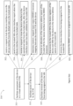
- Figures 4-8 illustrate example state diagrams for device interface assignment flow, in accordance with various embodiments. Operations illustrated in Figures 4-8 are detailed implementations for the interaction 311, the interaction 331, and the interaction 353, in example processes shown in Figures 3(a)-3(c) , which are for managing device interfaces performed by a device interface, a VM, and a hypervisor.
- Device interface assignment involves following steps: (1) Configuring and locking the interface using LOCK_INTERFACE_REQUEST; (2) Obtaining a DEVICE_INTERFACE_REPORT using GET DEVICE_INTERFACE_REPORT: (3) Verifying the configuration reported by the device in DEVICE_INTERFACE_REPORT; (4) If configurations are acceptable then accept the MMIO and DMA mappings to enable access to the device registers and to enable DMA from device to TD memory; and (5) If the configurations are acceptable then starting the interface using START_INTERFACE_REQUEST
- Step 1: Configure and Lock Interface - Figure 4 illustrates Step 1.
- VMM allocates a PASID and requests SEAM to assign PASID ownership to the TD.
- SEAM updates its internal tracking structures and adds a mapping in PASID translation structure in a pending (configured, but not present) state.
- VMM composes a virtual device (VDEV) representing one or more device interfaces.
- Device interface could be a PCIe physical function, a PCIe SR-IOV virtual function, or a Scalable IOV assignable device interface.
- VMM configures the device interface, executes LOCK_INTERFACE_REQUEST method on the device, and receives LOCK_INTERFACE_RESPONSE.
- VMM assigns VDEV to TD.
- TD enumerates VDEV and discovers different capabilities.
- TD requests creation of Trusted IOMMU mapping/s for the VDEV, resulting in VMM invoking SEAM to create the mapping/s in a pending (configured, but not present) state.
- TD allocates GPA space for hosting MMIO resources of the VDEV, and requests VMM to map MMIO resources for the VDEV (provides it the GPA ranges).
- VMM requests SEAM to create a Secure EPT mapping, providing it the required settings (e.g. shared or private MMIO page mapping), for associating GPA with a corresponding HPA.
- SEAM checks to ensure that MMIO page is not already mapped (if private mapping is requested), configures the ownership and settings for the page, and creates the mapping in Secure EPT in a pending (configured, but not present) state.
- Step 2 Obtain DEVICE INTERFACE REPORT - Figure 5 illustrates Step 2.
- TD requests VMM to get a DEVICE_INTERFACE_REPORT for each device interface associated with the VDEV (provides it the nonce/s).
- VMM requests SEAM to create a GET_DEVICE_INTERFACE_REPORT message, provides it the RID, PASID, interface ID, and the nonce received from the TD.
- VMM executes GET_DEVICE_INTERFACE_REPORT method on the device, and generates a DEVICE_INTERFACE_REPORT.
- VMM returns DEVICE_INTERFACE_REPORT/s received from the device to the TD for it to validate.
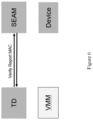
- Step 3 Verify DEVICE INTERFACE REPORT- Figure 6 illustrates Step 3.
- TD validates nonce in the report against the nonce sent to the VMM while requesting a report to ensure freshness of the report (to prevent against anti-reply attacks).
- TD validates the contents of the report (e.g. RID, PASID etc.). Since the DEVICE_INTERFACE_REPORT was passed through untrusted entities, TD needs to ensure that its contents are valid and have not been tempered with.
- TD generates hash for the report and requests SEAM to verify it against the MAC received inside the report (to prevent against man-in-the-middle attacks). If any of the checks fail, the DEVICE INTERFACE REPORT is marked invalid and assignment process is abandoned for the given VDEV.
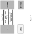
- Step 4 Accept MMIO and DMA mappings -
- Figure 7 illustrates Step 4.
- SEAM requests SEAM to accept (or activate) PASID.
- SEAM validates the PASID ownership and validates PASID translation before activating it.
- SEAM validates PASID ownership, validates IOMMU configuration against the desired IOMMU settings, and validates the translation and ownership of translation before activating it. If a valid FLPTR was provided, IOMMU mapping is activated as a nested-translation.
- TD For each MMIO page, TD requests SEAM to accept (or activate) Secure EPT MMIO mapping - providing it the GPA, desired Secure EPT settings (e.g. shared or private MMIO page mapping), and an MMIO offset information received in the DEVICE_INTERFACE_REPORT.
- SEAM calculates HPA based on the configured/stored MMIO base and the offset passed, validates ownership and settings for the page, validates GPA-HPA translation, and then finally activates the mapping.
- Step 5 Start the interface to move it to RUN state -
- Figure 8 illustrates Step 5.
- TD validates device interface configuration and requests SEAM to create a START_INTERFACE_REQUEST message - provides it the RID, PASID, interface ID, and nonce received in LOCK_INTERFACE_RESPONSE.
- TD requests VMM to start device interface/s.
- VMM executes START_INTERFACE_REQUEST method on the device for requested device interface/s, moving it/them to "Run” state if not already - provides it the START_INTERFACE_REQUEST message received from the TD.
- VMM notifies TD about the completion of the start interface request.
- Device interface can only accept or generate trusted transactions when in the "Run" state.
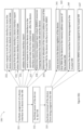
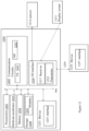
- Figures 9-11 illustrate example state diagrams for device interface removal flow, in accordance with various embodiments. Operations illustrated in Figures 9-11 are detailed implementations for the interaction 315, the interaction 335, and the interaction 357, in example processes shown in Figures 3(a)-3(c) , which are for managing device interfaces performed by a device interface, a VM, and a hypervisor.
- Device interface removal involves three steps: (1) Block DMA mapping to disable DMA from the device to TD memory and Issue a STOP INTERFACE REQUEST to the device; (2) On successful completion of the STOP INTERFACE REQUEST, relinquish MMIO access to the device, and (3) remove the MMIO and PASID resources assigned to the TD.
- Step 1 Block DMA mapping and clean device interface -
- Figure 9 illustrates Step 1.
- TD requests VMM to block Trusted IOMMU mapping, resulting in VMM invoking SEAM to block Trusted IOMMU mapping.
- SEAM deactivates the mapping (i.e. clears the present bit) and marks it to have a flush pending.
- VMM requests SEAM to queue invalidations associated with the Trusted IOMMU mapping, resulting in the mapping marked for flush started.
- VMM notifies SEAM for completion of queued invalidations, resulting in the mapping marked for flush completed.
- TD requests VMM to stop all the interfaces associated with VDEV, provides it a nonce.
- VMM requests SEAM to create a STOP_INTERFACE_REQUEST message, provides it the RID, PASID, and the nonce received from the TD.
- SEAM creates the STOP_INTERFACE_REQUEST message, after validating RID and PASID against Trusted IOMMU state, and returns the message to VMM.
- SEAM creates its own nonce and embeds it in STOP_INTERFACE_REQUEST.
- SEAM keeps a record of nonce embedded in the STOP_INTERFACE_REQUEST message to be able to validate the freshness of STOP_INTERFACE_RESPONSE when the processing is requested.
- VMM executes STOP_INTERFACE_REQUEST method on the device, cleaning up the state associated with the RID (and PASID if specified), and receives STOP_INTERFACE_RESPONSE from the device.
- VMM provides STOP INTERFACE RESPONSE to the TD.
- VMM requests SEAM to process STOP_INTERFACE_RESPONSE received from the device.
- TD validates nonce in the response, and requests SEAM to process the STOP_INTERFACE_RESPONSE to determine the authenticity of the response.
- successful processing of STOP_INTERFACE_RESPONSE results in IOMMU mapping marked for cleanup completed. It should be appreciated that, in some embodiments, some of these operations can be re-arranged or combined. For example, in some embodiments, the device interface is stopped first before the Trusted IOMMU mapping is blocked. For example, in some embodiments, SEAM queues IOMMU invalidations just after blocking the Trusted IOMMU mapping.
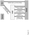
- Step 2 Relinquish MMIO mapping - Figure 10 illustrates Step 2.
- TD starts the process of relinquishing MMIO mappings.
- SEAM For each MMIO page, TD requests SEAM to release Secure EPT MMIO mapping, providing it a GPA.
- SEAM performs GPA-HPA translation, validates ownership for the page, and marks the page as released by TD.
- TD requests VMM to remove MMIO mappings associated with the VDEV.
- VMM requests SEAM to block MMIO mapping in the Secure EPT. SEAM ensures that TD has released the page or TD is stopped and all PASIDs have been removed from this stopped TD.
- SEAM deactivates the mapping (i.e. clears the present bit) and marks the page for CPU and IOMMU-based invalidations pending.
- VMM performs CPU TLB invalidation, and notifies SEAM about the completion.
- VMM requests SEAM to queue IOMMU-based invalidations associated with the Secure EPT change.
- VMM notifies SEAM about the completion of IOMMU-based invalidations.
- VMM notifies TD about the completion MMIO mappings removal. It should be appreciated that, in some embodiments, some of these operations can be combined. For example, SEAM can queue IOMMU-based invalidations just after changing Secure EPT mapping.
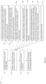
- Step 3 Remove resources assigned to the device interface - Figure 11 illustrates Step 3.
- VMM requests SEAM to remove Trusted IOMMU mapping. SEAM ensures that cleanup is completed for the Trusted IOMMU mapping, before it can be removed.
- VMM requests SEAM to remove the MMIO mapping in the Secure EPT. SEAM ensures that, Secure EPT mapping is in a blocked state, CPU and IOMMU-based invalidation are completed for the mapping.
- VMM requests SEAM to remove PASID mapping. SEAM ensures that PASID is not being referenced by IOMMU structures, removes PASID translation mapping, and updates internal tracking structures for the PASID removal.
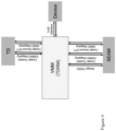
- FIG. 12 illustrates an example device suitable for use to practice various aspects of the present disclosure, in accordance with various embodiments.
- the device 1200 may be used to implement functions of the apparatus 100.
- the device 1200 may include one or more processors 1202, each having one or more processor cores, or and optionally, a hardware accelerator 1203 (which may be an ASIC or a FPGA).
- the hardware accelerator 1203 may be part of processor 1202, or integrated together on a SOC.
- the device 1200 may include a memory 1204, which may be any one of a number of known persistent storage medium, and a data storage circuitry 1208 including modules 1209.
- the 1200 may include an I/O interface 1218, coupled to one or more sensors 1214, and a display screen 1213.
- the I/O interface 1218 may include a transmitter 1223 and a receiver 1217.
- the device 1200 may include communication circuitry 1205 including a transceiver (Tx) 1211, and network interface controller (NIC) 1212.
- Tx transceiver
- NIC network interface controller
- the elements may be coupled to each other via system bus 1206, which may represent one or more buses. In the case of multiple buses, they may be bridged by one or more bus bridges (not shown).
- a device 1231 may be coupled to the system bus 1206, and a device 1235 may be coupled to a computer bus 1239.
- the device 1231 may include an interface 1233, and the device 1235 may include an interface 1237.
- the computer bus 1206 or the computer bus 1239 may be an example of the computer bus 105 as shown in Figure 1 .
- processor(s) 1202 may be one or more processing elements configured to perform basic arithmetical, logical, and input/output operations by carrying out instructions.
- processor circuitry 1202 may be implemented as a standalone system/device/package or as part of an existing system/device/package.
- the processor circuitry 1202 may be one or more microprocessors, one or more single-core processors, one or more multi-core processors, one or more multithreaded processors, one or more GPUs, one or more ultra-low voltage processors, one or more embedded processors, one or more DSPs, one or more FPDs (hardware accelerators) such as FPGAs, structured ASICs, programmable SoCs (PSoCs), etc., and/or other processor or processing/controlling circuit.
- the processor circuitry 1202 may be a part of a SoC in which the processor circuitry 1202 and other components discussed herein are formed into a single IC or a single package.
- the processor circuitry 1202 may include one or more Intel Pentium, Core, Xeon, Atom, or Core M processor(s); Advanced Micro Devices (AMD) Accelerated Processing Units (APUs), Epyc, or Ryzen processors; Apple Inc. A series, S series, W series, etc. processor(s); Qualcomm snapdragon processor(s); Samsung Exynos processor(s); and/or the like.
- the processor circuitry 1202 may include a sensor hub, which may act as a coprocessor by processing data obtained from the one or more sensors 1214.
- the sensor hub may include circuitry configured to integrate data obtained from each of the one or more sensors 1214 by performing arithmetical, logical, and input/output operations.
- the sensor hub may capable of timestamping obtained sensor data, providing sensor data to the processor circuitry 1202 in response to a query for such data, buffering sensor data, continuously streaming sensor data to the processor circuitry 1202 including independent streams for each sensor of the one or more sensors 1214, reporting sensor data based upon predefined thresholds or conditions/triggers, and/or other like data processing functions.
- the memory 1204 (also referred to as "memory circuitry 1204" or the like) may be circuitry configured to store data or logic for operating the computer device 1200.
- the memory circuitry 1204 may include number of memory devices may be used to provide for a given amount of system memory.
- the memory circuitry 1204 can be any suitable type, number and/or combination of volatile memory devices (e.g., random access memory (RAM), dynamic RAM (DRAM), static RAM (SAM), etc.) and/or non-volatile memory devices (e.g., read-only memory (ROM), erasable programmable read-only memory (EPROM), electrically erasable programmable read-only memory (EEPROM), flash memory, antifuses, etc.) that may be configured in any suitable implementation as are known.
- volatile memory devices e.g., random access memory (RAM), dynamic RAM (DRAM), static RAM (SAM), etc.
- non-volatile memory devices e.g., read-only memory (ROM), erasable programmable read-only memory (EPROM), electrically erasable programmable read-only memory (EEPROM), flash memory, antifuses, etc.
- ROM read-only memory
- EPROM erasable programmable read-only memory
- EEPROM electrically erasable programmable
- individual memory devices may be formed of any number of different package types, such as single die package (SDP), dual die package (DDP) or quad die package, dual inline memory modules (DIMMs) such as microDIMMs or MiniDIMMs, and/or any other like memory devices.
- SDP single die package
- DDP dual die package
- DIMMs dual inline memory modules
- microDIMMs microDIMMs or MiniDIMMs
- the memory circuitry 1204 may include one or more mass-storage devices, such as a solid state disk drive (SSDD); flash memory cards, such as SD cards, microSD cards, xD picture cards, and the like, and USB flash drives; on-die memory or registers associated with the processor circuitry 1202 (for example, in low power implementations); a micro hard disk drive (HDD); three dimensional cross-point (3D XPOINT) memories from Intel and Micron, etc.
- SSDD solid state disk drive
- flash memory cards such as SD cards, microSD cards, xD picture cards, and the like, and USB flash drives
- on-die memory or registers associated with the processor circuitry 1202 for example, in low power implementations
- HDD micro hard disk drive
- 3D XPOINT three dimensional cross-point
- the processor circuitry 1202 and memory circuitry 1204 may comprise logic blocks or logic fabric, memory cells, input/output (I/O) blocks, and other interconnected resources that may be programmed to perform various functions of the example embodiments discussed herein.
- the memory cells may be used to store data in lookup-tables (LUTs) that are used by the processor circuitry 1202 to implement various logic functions.
- LUTs lookup-tables
- the memory cells may include any combination of various to implement various logic functions.
- the memory cells may include any combination of various levels of memory/storage including, but not limited to, EPROM, EEPROM, flash memory, SRAM, anti-fuses, etc.
- the data storage circuitry 1208 may provide for persistent storage of information such as modules 1209, operating systems, etc.
- the data storage circuitry 1208 may be implemented as solid state drives (SSDs); solid state disk drive (SSDD); serial AT attachment (SATA) storage devices (e.g., SATA SSDs); flash drives; flash memory cards, such as SD cards, microSD cards, xD picture cards, and the like, and USB flash drives; three-dimensional cross-point (3D Xpoint) memory devices; on-die memory or registers associated with the processor circuitry 1202; hard disk drives (HDDs); micro HDDs; resistance change memories; phase change memories; holographic memories; or chemical memories; among others.
- the data storage circuitry 1208 is included in the computer device 1200; however, in other embodiments, the data storage circuitry 1208 may be implemented as one or more devices separated from the other elements of computer device 1200.
- the data storage circuitry 1208 may include an operating system (OS) (not shown), which may be a general purpose operating system or an operating system specifically written for and tailored to the computer device 1200.
- the OS may include one or more drivers, libraries, and/or application programming interfaces (APIs), which provide program code and/or software components for modules 1209 and/or control system configurations to control and/or obtain/process data from the one or more sensors 1214.
- APIs application programming interfaces
- the modules 1209 may be software modules/components used to perform various functions of the computer device 1200 and/or to carry out functions of the example embodiments discussed herein.
- the processor circuitry 1202 and memory circuitry 1204 includes hardware accelerators (e.g., FPGA cells, the hardware accelerator 1203) as well as processor cores
- the hardware accelerators e.g., the FPGA cells
- the modules 1209 may comprise logic for the corresponding entities discussed with regard to the display screen 1213, the transmitter 1223, and the receiver 1217.
- the components of computer device 1200 may communicate with one another over the bus 1206.
- the bus 1206 may include any number of technologies, such as a Local Interconnect Network (LIN); industry standard architecture (ISA); extended ISA (EISA); PCI; PCI extended (PCIx); PCIe; an Inter-Integrated Circuit (I2C) bus; a Parallel Small Computer System Interface (SPI) bus; Common Application Programming Interface (CAPI); point to point interfaces; a power bus; a proprietary bus, for example, Intel Ultra Path Interface (UPI), Intel Accelerator Link (IAL), or some other proprietary bus used in a SoC based interface; or any number of other technologies.
- LIN Local Interconnect Network
- ISA industry standard architecture
- EISA extended ISA
- PCI PCI extended
- PCIe PCIe
- I2C Inter-Integrated Circuit
- SPI Parallel Small Computer System Interface
- CAI Common Application Programming Interface
- point to point interfaces a power bus
- a proprietary bus for example, Intel Ultra Path Interface (UPI), Intel Accel
- the bus 1206 may be a controller area network (CAN) bus system, a Time-Trigger Protocol (TTP) system, or a FlexRay system, which may allow various devices (e.g., the one or more sensors 1214, etc.) to communicate with one another using messages or frames.
- CAN controller area network
- TTP Time-Trigger Protocol
- FlexRay FlexRay system
- the communications circuitry 1205 may include circuitry for communicating with a wireless network or wired network.
- the communication circuitry 1205 may include transceiver (Tx) 1211 and network interface controller (NIC) 1212.
- Communications circuitry 1205 may include one or more processors (e.g., baseband processors, modems, etc.) that are dedicated to a particular wireless communication protocol.
- NIC 1212 may be included to provide a wired communication link to a network and/or other devices.
- the wired communication may provide an Ethernet connection, an Ethernet-over-USB, and/or the like, or may be based on other types of networks, such as DeviceNet, ControlNet, Data Highway+, PROFIBUS, or PROFINET, among many others.
- An additional NIC 1212 may be included to allow connect to a second network (not shown) or other devices, for example, a first NIC 1212 providing communications to the network over Ethernet, and a second NIC 1212 providing communications to other devices over another type of network, such as a personal area network (PAN) including a personal computer (PC) device.
- PAN personal area network
- PC personal computer
- the various components of the device 1200 may be connected to the processor(s) 1202 via the NIC 1212 as discussed above rather than via the I/O circuitry 1218 as discussed infra.
- the Tx 1211 may include one or more radios to wirelessly communicate with a network and/or other devices.
- the Tx 1211 may include hardware devices that enable communication with wired networks and/or other devices using modulated electromagnetic radiation through a solid or non-solid medium.
- Such hardware devices may include switches, filters, amplifiers, antenna elements, and the like to facilitate the communications over the air (OTA) by generating or otherwise producing radio waves to transmit data to one or more other devices, and converting received signals into usable information, such as digital data, which may be provided to one or more other components of computer device 1200.
- the various components of the device 1200 such as the one or more sensors 1214, etc. may be connected to the device 1200 via the Tx 1211 as discussed above rather than via the I/O circuitry 1218 as discussed infra.
- the one or more sensors 1214 may be coupled with device 1200 via a short range communication protocol.
- the Tx1211 may include one or multiple radios that are compatible with any number of 3GPP (Third Generation Partnership Project) specifications, notably Long Term Evolution (LTE), Long Term Evolution-Advanced (LTE-A), Long Term Evolution-Advanced Pro (LTE-A Pro), and Fifth Generation (5G) New Radio (NR).
- LTE Long Term Evolution
- LTE-A Long Term Evolution-Advanced
- LTE-A Pro Long Term Evolution-Advanced Pro
- NR Fifth Generation
- radios compatible with any number of other fixed, mobile, or satellite communication technologies and standards may be selected. These may include, for example, any Cellular Wide Area radio communication technology, which may include e.g. a 5G communication systems, a Global System for Mobile Communications (GSM) radio communication technology, a General Packet Radio Service (GPRS) radio communication technology, or an Enhanced Data Rates for GSM Evolution (EDGE) radio communication technology.
- GSM Global System for Mobile Communications
- GPRS General Packet Radio Service
- 3GPP Third Generation Partnership Project
- 3GPP Universal Mobile Telecommunications System
- FOMA Freedom of Multimedia Access
- 3 GPP LTE Long Term Evolution
- 3GPP LTE Advanced Long Term Evolution Advanced
- 3GPP LTE Advanced Pro Long Term Evolution Advanced Pro
- CDMA2000 Code division multiple access 2000
- CDPD Cellular Digital Packet Data
- Mobitex 3G (Third Generation)
- CSD Circuit Switched Data
- HSCSD High-Speed Circuit-Switched Data
- UMTS (3G) Universal Mobile Telecommunications System (Third Generation)
- W-CDMA UMTS
- HSPA High Speed Packet Access
- HSDPA High-Speed Downlink Packet Access
- HSUPA High-Speed Uplink Packet Access
- HSPA+ High Speed Packet Access Plus
- UMTS-TDD Universal Mobile Telecommunications System -
- Pre-4G (3rd Generation Partnership Project Release 8 (Pre-4th Generation)
- 3GPP Rel. 9 (3rd Generation Partnership Project Release 9)
- 3GPP Rel. 10 (3rd Generation Partnership Project Release 10)
- 3GPP Rel. 11 (3rd Generation Partnership Project Release 11)
- 3GPP Rel. 12 (3rd Generation Partnership Project Release 12)
- 3GPP Rel. 13 (3rd Generation Partnership Project Release 13), 3GPP Rel.
- any number of satellite uplink technologies may be used for the uplink transceiver, including, for example, radios compliant with standards issued by the ITU (International Telecommunication Union), or the ETSI (European Telecommunications Standards Institute), among others.
- ITU International Telecommunication Union
- ETSI European Telecommunications Standards Institute
- the examples provided herein are thus understood as being applicable to various other communication technologies, both existing and not yet formulated. Implementations, components, and details of the aforementioned protocols may be those known in the art and are omitted herein for the sake of brevity.
- the input/output (I/O) interface 1218 may include circuitry, such as an external expansion bus (e.g., Universal Serial Bus (USB), FireWire, Thunderbolt, PCI/PCIe/PCIx, etc.), used to connect computer device 1200 with external components/devices, such as one or more sensors 1214, etc.
- I/O interface circuitry 1218 may include any suitable interface controllers and connectors to interconnect one or more of the processor circuitry 1202, memory circuitry 1204, data storage circuitry 1208, communication circuitry 1205, and the other components of computer device 1200.
- the interface controllers may include, but are not limited to, memory controllers, storage controllers (e.g., redundant array of independent disk (RAID) controllers, baseboard management controllers (BMCs), input/output controllers, host controllers, etc.
- the connectors may include, for example, busses (e.g., bus 1206), ports, slots, jumpers, interconnect modules, receptacles, modular connectors, etc.
- the I/O circuitry 1218 may couple the device 1200 with the one or more sensors 1214, etc.
- a wired connection such as using USB, FireWire, Thunderbolt, RCA, a video graphics array (VGA), a digital visual interface (DVI) and/or mini-DVI, a high-definition multimedia interface (HDMI), an S-Video, and/or the like.
- VGA video graphics array
- DVI digital visual interface
- HDMI high-definition multimedia interface
- S-Video S-Video
- the one or more sensors 1214 may be any device configured to detect events or environmental changes, convert the detected events into electrical signals and/or digital data, and transmit/send the signals/data to the computer device 1200. Some of the one or more sensors 1214 may be sensors used for providing computer-generated sensory inputs. Some of the one or more sensors 1214 may be sensors used for motion and/or object detection. Examples of such one or more sensors 1214 may include, inter alia, charged-coupled devices (CCD), Complementary metal-oxide-semiconductor (CMOS) active pixel sensors (APS), lens-less image capture devices/cameras, thermographic (infrared) cameras, Light Imaging Detection And Ranging (LIDAR) systems, and/or the like.
- CCD charged-coupled devices
- CMOS Complementary metal-oxide-semiconductor
- APS active pixel sensors
- lens-less image capture devices/cameras thermographic (infrared) cameras
- LIDAR Light Imaging Detection And Rang
- the one or more sensors 1214 may include a lens-less image capture mechanism comprising an array of aperture elements, wherein light passing through the array of aperture elements define the pixels of an image.
- the motion detection one or more sensors 1214 may be coupled with or associated with light generating devices, for example, one or more infrared projectors to project a grid of infrared light onto a scene, where an infrared camera may record reflected infrared light to compute depth information.
- the one or more sensors 1214 may be used for position and/or orientation detection, ambient/environmental condition detection, and the like.
- Examples of such one or more sensors 1214 may include, inter alia, microelectromechanical systems (MEMS) with piezoelectric, piezoresistive and/or capacitive components, which may be used to determine environmental conditions or location information related to the computer device 1200.
- MEMS microelectromechanical systems
- the MEMS may include 3-axis accelerometers, 3-axis gyroscopes, and/or magnetometers.
- the one or more sensors 1214 may also include one or more gravimeters, altimeters, barometers, proximity sensors (e.g., infrared radiation detector(s) and the like), depth sensors, ambient light sensors, thermal sensors (thermometers), ultrasonic transceivers, and/or the like.
- proximity sensors e.g., infrared radiation detector(s) and the like
- depth sensors e.g., ambient light sensors, thermal sensors (thermometers), ultrasonic transceivers, and/or the like.
- Each of these elements may perform its conventional functions known in the art.
- they may be employed to store and host execution of programming instructions implementing the operations associated with resources sharing across multiple flow-control class and virtual channels in computer buses, as described in connection with Figures 1-11 , and/or other functions that provides the capability of the embodiments described in the current disclosure.
- the various elements may be implemented by assembler instructions supported by processor(s) 1202 or high-level languages, such as, for example, C, that can be compiled into such instructions. Operations associated with the device 1200 not implemented in software may be implemented in hardware, e.g., via hardware accelerator 1203.
- the number, capability and/or capacity of these elements 1202-1239 may vary, depending on the number of other devices the device 1200 is configured to support. Otherwise, the constitutions of elements 1202-1239 are known, and accordingly will not be further described.
- the present disclosure may be embodied as methods or computer program products. Accordingly, the present disclosure, in addition to being embodied in hardware as earlier described, may take the form of an entirely software embodiment (including firmware, resident software, micro-code, etc.) or an embodiment combining software and hardware aspects that may all generally be referred to as a "circuit,” “module,” or “system.”
- FIG. 13 illustrates an example computer-readable non-transitory storage medium that may be suitable for use to store instructions that cause an apparatus, in response to execution of the instructions by the apparatus, to practice selected aspects of the present disclosure.
- non-transitory computer-readable storage medium 1302 may include a number of programming instructions 1304.
- Programming instructions 1304 may be configured to enable a device, e.g., device 1300, in response to execution of the programming instructions, to perform, e.g., various operations associated with resources sharing across multiple flow-control class and virtual channels in computer buses, as shown in Figures 1-12 .
- programming instructions 1304 may be disposed on multiple computer-readable non-transitory storage media 1302 instead. In alternate embodiments, programming instructions 1304 may be disposed on computer-readable transitory storage media 1302, such as, signals. Any combination of one or more computer usable or computer readable medium(s) may be utilized.
- the computer-usable or computer-readable medium may be, for example but not limited to, an electronic, magnetic, optical, electromagnetic, infrared, or semiconductor system, apparatus, device, or propagation medium.
- the computer-readable medium would include the following: an electrical connection having one or more wires, a portable computer diskette, a hard disk, a random access memory (RAM), a read-only memory (ROM), an erasable programmable read-only memory (EPROM or Flash memory), an optical fiber, a portable compact disc read-only memory (CD-ROM), an optical storage device, a transmission media such as those supporting the Internet or an intranet, or a magnetic storage device.
- RAM random access memory
- ROM read-only memory
- EPROM or Flash memory erasable programmable read-only memory
- CD-ROM compact disc read-only memory
- CD-ROM compact disc read-only memory
- a transmission media such as those supporting the Internet or an intranet, or a magnetic storage device.
- a computer-usable or computer-readable medium could even be paper or another suitable medium upon which the program is printed, as the program can be electronically captured, via, for instance, optical scanning of the paper or other medium, then compiled, interpreted, or otherwise processed in a suitable manner, if necessary, and then stored in a computer memory.
- a computer-usable or computer-readable medium may be any medium that can contain, store, communicate, propagate, or transport the program for use by or in connection with the instruction execution system, apparatus, or device.
- the computer-usable medium may include a propagated data signal with the computer-usable program code embodied therewith, either in baseband or as part of a carrier wave.
- the computer usable program code may be transmitted using any appropriate medium, including but not limited to wireless, wireline, optical fiber cable, RF, etc.
- Computer program code for carrying out operations of the present disclosure may be written in any combination of one or more programming languages, including an object oriented programming language such as Java, Smalltalk, C++ or the like and conventional procedural programming languages, such as the "C" programming language or similar programming languages.
- the program code may execute entirely on the user's computer, partly on the user's computer, as a stand-alone software package, partly on the user's computer and partly on a remote computer or entirely on the remote computer or server.
- the remote computer may be connected to the user's computer through any type of network, including a local area network (LAN) or a wide area network (WAN), or the connection may be made to an external computer (for example, through the Internet using an Internet Service Provider).
- LAN local area network
- WAN wide area network
- Internet Service Provider for example, AT&T, MCI, Sprint, EarthLink, MSN, GTE, etc.
- These computer program instructions may also be stored in a computer-readable medium that can direct a computer or other programmable data processing apparatus to function in a particular manner, such that the instructions stored in the computer-readable medium produce an article of manufacture including instruction means which implement the function/act specified in the flowchart and/or block diagram block or blocks.
- the computer program instructions may also be loaded onto a computer or other programmable data processing apparatus to cause a series of operational steps to be performed on the computer or other programmable apparatus to produce a computer implemented process such that the instructions which execute on the computer or other programmable apparatus provide processes for implementing the functions/acts specified in the flowchart and/or block diagram block or blocks.
- each block in the flowchart or block diagrams may represent a module, segment, or portion of code, which comprises one or more executable instructions for implementing the specified logical function(s).
- the functions noted in the block may occur out of the order noted in the figures. For example, two blocks shown in succession may, in fact, be executed substantially concurrently, or the blocks may sometimes be executed in the reverse order, depending upon the functionality involved.
- Embodiments may be implemented as a computer process, a computing system or as an article of manufacture such as a computer program product of computer readable media.
- the computer program product may be a computer storage medium readable by a computer system and encoding a computer program instructions for executing a computer process.
Landscapes
- Engineering & Computer Science (AREA)
- Theoretical Computer Science (AREA)
- Software Systems (AREA)
- General Engineering & Computer Science (AREA)
- General Physics & Mathematics (AREA)
- Physics & Mathematics (AREA)
- Computer Hardware Design (AREA)
- Computer Security & Cryptography (AREA)
- Computing Systems (AREA)
- Computer Networks & Wireless Communication (AREA)
- Signal Processing (AREA)
- Bus Control (AREA)
- Storage Device Security (AREA)
Claims (11)
- Vorrichtung (204), umfassend:eine Vorrichtungsschnittstelle (206), die konfiguriert ist zum Vereinfachen einer Zuteilung (311) der Vorrichtung (204) zu einer virtuellen Maschine, VM (211), die von einem Hypervisor (202) einer Computerplattform (200) verwaltet wird, die durch einen Computerbus (205) mit der Vorrichtung (204) gekoppelt ist, eines Zugriffs (313) auf die Vorrichtung (204) durch die VM (211) oder eines Entfernens (315) der Vorrichtung (204) aus der Zuteilung zu der VM (211);wobei die Vorrichtungsschnittstelle (206) eine Logik (209) zum Unterstützen eines Vorrichtungsverwaltungsprotokolls beinhaltet und konfiguriert ist zum:
Versetzen der Vorrichtungsschnittstelle (206) in:einen entsperrten Zustand (231) als einen voreingestellten Zustand der Vorrichtung (204),einen gesperrten Zustand (233), um zu vermeiden, dass Veränderungen an der Vorrichtungsschnittstelle (206) vorgenommen werden,einen Betriebszustand (235), um einen Zugriff auf Vorrichtungsregister der Vorrichtung (204) durch die VM (211) oder einen direkten Speicherzugriff, DMA, von der Vorrichtung (204) auf die Speicheradressenplätze der VM (211) zu ermöglichen, odereinen Fehlerzustand, um anzuzeigen, dass ein Fehler aufgetreten ist;dadurch gekennzeichnet, dassdie Logik (209) zum Unterstützen eines Vorrichtungsverwaltungsprotokolls ferner konfiguriert ist zum:Melden einer Konfiguration der Vorrichtungsschnittstelle (206) an die VM (211), wenn sie sich in dem gesperrten Zustand (233) befindet, und ferner zum Zurückweisen eines nicht vertrauenswürdigen Zugriffs auf den Registerzustand der Vorrichtung (204), wenn sie sich in dem gesperrten Zustand (233) befindet;Versetzen der Vorrichtungsschnittstelle (206) aus dem gesperrten Zustand (233) in den Betriebszustand (235), wenn die Vorrichtung (204) der VM (211) zugeteilt wird und ferner durch einen Sicherheitsberechtigungsnachweis autorisiert wurde, der von der VM (211) bereitgestellt wird; undVersetzen der Vorrichtungsschnittstelle (206) in den entsperrten Zustand (231), wenn die Vorrichtungsschnittstelle (206) aus der Zuteilung zu der VM (211) entfernt wird oder wenn eine Fehlerbedingung erkannt wird, welche die Schnittstellenzuteilung beeinträchtigt, Stoppen des Zugriffs durch die VM (211) auf die Vorrichtungsregister der Vorrichtung (204) oder des DMA durch die Vorrichtung (204) auf die Speicherplätze der VM (211). - Vorrichtung (204) nach Anspruch 1, wobei die VM (211) eine vertrauenswürdige VM (211) ist, deren Speicherinhalte und Zustände der zentralen Verarbeitungseinheit, CPU, von dem Hypervisor (202) und anderen VMs (216, 218), die von dem Hypervisor (202) verwaltet werden, vertraulich gehalten werden, und wobei die Logik (209) zum Unterstützen des Vorrichtungsverwaltungsprotokolls ferner konfiguriert ist zum Versetzen der Vorrichtungsschnittstelle (206)in einer sicheren Weise in den entsperrten Zustand (231), in den gesperrten Zustand (233) oder in den Betriebszustand (235).
- Vorrichtung (204) nach Anspruch 2, wobei, wenn die Vorrichtungsschnittstelle (206) in der sicheren Weise in den entsperrten Zustand (231), in den gesperrten Zustand (233) oder in den Betriebszustand (235) versetzt wird, die Logik (209) zum Unterstützen des Vorrichtungsverwaltungsprotokolls ferner konfiguriert ist zum Authentifizieren der Vorrichtung (204) und zum Verhandeln eines Verbindungsverschlüsselungsschlüssels mit der Vorrichtung (204), um Kommunikationen zwischen der Vorrichtung (204) und der vertrauenswürdigen VM (211) abzusichern, bevor die Vorrichtungsschnittstelle (206) der Vorrichtung (204) der vertrauenswürdigen VM (211) zugeteilt wird, und
wobei die Vorrichtung (204) dazu dient, vertrauenswürdige Datenpakete auf Transaktionsebene (Transaction Level Packets, TLPs) von der vertrauenswürdigen VM (211) zu akzeptieren oder vertrauenswürdige TLPs zu erzeugen, die an die vertrauenswürdige VM (211) gesendet werden, wenn sie sich in dem Betriebszustand (235) befindet. - Vorrichtung (204) nach Anspruch 1, wobei die Vorrichtungsschnittstelle (206) eine physische Funktion, eine virtuelle Funktion oder eine zuteilbare Vorrichtungsschnittstelle beinhaltet.
- Ein oder mehrere nicht-flüchtige computerlesbare Medien, in denen Anweisungen enthalten sind, die als Reaktion auf eine Ausführung der Anweisungen durch einen oder mehrere Hardwareprozessoren einer Computerplattform (200) eine virtuelle Maschine, VM (211) auf der Computerplattform (200) bereitstellen, wobei die VM (211) eine vertrauenswürdige VM (211) ist, deren Speicherinhalte und Prozessorzustände der vertrauenswürdigen VM (211) von dem Hypervisor (202) und anderen VMs (211), die von dem Hypervisor (202) verwaltet werde, vertraulich gehalten werden, wobei die VM (211) beinhaltet:einen Vorrichtungstreiber (214), der konfiguriert ist zum Vereinfachen einer Zuteilung (331) einer Vorrichtungsschnittstelle (206) für eine Vorrichtung (204) zu der VM (211), die von einem Hypervisor (202) der Computerplattform (200) verwaltet wird, eines Zugriffs (333) auf die Vorrichtung (204) durch die VM (211) oder eines Entfernens (315) der Vorrichtung (204) aus der Zuteilung zu der VM (211), wobei die Vorrichtung (204) durch einen Computerbus (205) mit der Computerplattform (200) gekoppelt ist; undwobei der Vorrichtungstreiber (214) eine Unterstützung eines Vorrichtungsverwaltungsprotokolls beinhaltet, um zu veranlassen, dass die Vorrichtungsschnittstelle (206) in einen voreingestellten entsperrten Zustand (231), in einen gesperrten Zustand (233), um zu vermeiden, dass Veränderungen an der Vorrichtungsschnittstelle (206) vorgenommen werden, in einen Betriebszustand (235), um einen Zugriff auf Vorrichtungsregister der Vorrichtung (204) durch die VM (211) oder einen direkten Speicherzugriff, DMA, von der Vorrichtung (204) auf die Speicheradressenplätze der VM (211) zu ermöglichen, oder in einen Fehlerzustand versetzt wird, um anzuzeigen, dass ein Fehler aufgetreten ist,wobei der Vorrichtungstreiber (214) zum Vereinfachen (331) der Zuteilung der Vorrichtungsschnittstelle (206) für die Vorrichtung(204) zu der vertrauenswürdigen VM (211) konfiguriert ist zum:Senden (332) einer Anforderung zum Sperren der Vorrichtungsschnittstelle (206), um die Vorrichtungsschnittstelle (206) aus dem voreingestellten Zustand in den gesperrten Zustand (233) zu versetzen;Empfangen (334), von der Vorrichtungsschnittstelle (206), eines Berichts der Vorrichtungsschnittstelle (206), wenn sich die Vorrichtungsschnittstelle (206) in dem gesperrten Zustand (233) befindet;Validieren (336) des Berichts der Vorrichtungsschnittstelle (206); undSenden (337) einer Anforderung, um die Vorrichtungsschnittstelle (206) aus dem gesperrten Zustand (233) in den Betriebszustand (235) zu versetzen, nachdem der Bericht der Vorrichtungsschnittstelle (206) validiert wurde;wobei der Vorrichtungstreiber (214) zum Unterstützen des Vorrichtungsverwaltungsprotokolls dazu dient, um zu veranlassen, dass die Vorrichtungsschnittstelle (206) in einer sicheren Weise in den entsperrten Zustand (231), in den gesperrten Zustand (233) oder in den Betriebszustand (235) versetzt wird.
- Computerplattform (200), umfassend:einen oder mehrere Prozessoren; undeinen Hypervisor (202), der geeignet ist, zum Betreiben des einen oder der mehreren Prozessoren, wobei der Hypervisor (202) geeignet ist zum:Verwalten von Operationen einer virtuellen Maschine, VM; undVereinfachen einer Zuteilung (331) einer Vorrichtungsschnittstelle (206) einer Vorrichtung (204) zu der VM (211), eines Zugriffs (333) auf die Vorrichtung (204) durch die VM (211) oder eines Entfernens (335) der Vorrichtung (204) aus der Zuteilung zu der VM (211);wobei die Vorrichtung (204) durch einen Computerbus (205) mit der Computerplattform (200) gekoppelt ist, undwobei die Vorrichtungsschnittstelle (206) eine Logik (209) zum Unterstützen eines Vorrichtungsverwaltungsprotokolls beinhaltet, um die Vorrichtungsschnittstelle (206) in einen entsperrten Zustand (231) als einen voreingestellten Zustand der Vorrichtung (204), in einen gesperrten Zustand (233), um zu vermeiden, dass Veränderungen an der Vorrichtungsschnittstelle (206) vorgenommen werden, in einen Betriebszustand (235), um einen Zugriff auf Vorrichtungsregister der Vorrichtung (204) durch die VM (211) oder einen direkten Speicherzugriff, DMA, von der Vorrichtung (204) auf die Speicheradressenplätze der VM (211) zu ermöglichen, oder in einen Fehlerzustand versetzt wird, um anzuzeigen, dass ein Fehler aufgetreten ist;wobei der Hypervisor (202) ferner konfiguriert ist zum:Empfangen, von der Vorrichtungsschnittstelle (206) eines Konfigurationsberichts der Vorrichtungsschnittstelle(206),Anweisen der Vorrichtungsschnittstelle (206), dass sie aus dem gesperrten Zustand (233) in den Betriebszustand (235) versetzt wird, wenn die Vorrichtung (204) der VM (211) zugeteilt wird, undAnweisen der Vorrichtungsschnittstelle (206), dass sie in den entsperrten Zustand (231) versetzt wird, wenn die Vorrichtungsschnittstelle (206) aus der Zuteilung zu der VM (211) entfernt wird, wodurch der Zugriff durch die VM (211) auf die Vorrichtungsregister der Vorrichtung (204) oder der DMA durch die Vorrichtung (204) auf die Speicherplätze der VM (211) gestoppt wird.
- Computerplattform (200) nach Anspruch 6, wobei die VM (211) eine vertrauenswürdige VM (211) ist, deren Speicherinhalte und die Zustände der zentralen Verarbeitungseinheit, CPU, der vertrauenswürdigen VM (211) von dem Hypervisor (202) und anderen VMs (211), die von dem Hypervisor (202) verwaltet werden, vertraulich gehalten werden, und wobei das Vereinfachen einer Zuteilung der Vorrichtungsschnittstelle (206) der Vorrichtung (204) zu der vertrauenswürdigen VM (211) beinhaltet:Authentifizieren der Vorrichtung (204) und Verhandeln eines Verbindungsverschlüsselungsschlüssels, um Kommunikationen zwischen der Vorrichtung (204) und der vertrauenswürdigen VM (211) abzusichern, bevor die Vorrichtungsschnittstelle (206) der Vorrichtung (204) der vertrauenswürdigen VM (211) zugeteilt wird, undwenn sich die Vorrichtungsschnittstelle (206) in dem Betriebszustand (235) befindet, Übertragen und Empfangen von vertrauenswürdigen Datenpaketen auf Transaktionsebene (Transaction Level Packets, TLPs) zwischen der vertrauenswürdigen VM (211) und der Vorrichtung (204).
- Computerplattform (200) nach Anspruch 6, wobei der Hypervisor (202) zum Vereinfachen der Zuteilung der Vorrichtungsschnittstelle (206) der Vorrichtung (204) zu der VM (211) geeignet ist zum:Konfigurieren der Vorrichtungsschnittstelle (206), um der VM (211) zugeteilt zu werden;Zusammenstellen einer virtuellen Vorrichtung, VDEV, gestützt auf die Vorrichtungsschnittstelle (206);Senden einer Anforderung zum Sperren der Vorrichtungsschnittstelle (206), um die Vorrichtungsschnittstelle (206) aus dem voreingestellten Zustand in den gesperrten Zustand (233) zu versetzen;Empfangen, von der Vorrichtungsschnittstelle (206), eines Berichts der Vorrichtungsschnittstelle (206), wenn sich die Vorrichtungsschnittstelle (206) in dem gesperrten Zustand (233) befindet; undZuteilen der VDEV zu der VM (211).
- Ein oder mehrere nicht-flüchtige computerlesbare Medien, in denen Anweisungen enthalten sind, die als Reaktion auf eine Ausführung der Anweisungen durch einen oder mehrere Hardwareprozessoren einer Computerplattform (200) ein Ressourcenvermittlungsmodul (203) bereitstellen, das geeignet ist, um durch einen Hypervisor (202) auf der Computerplattform (200) betrieben zu werden zum:Verwalten einer Zuteilung (351) einer Vorrichtungsschnittstelle (206) für eine Vorrichtung (204) zu einer virtuellen Maschine, VM (211), die von dem Hypervisor (202) verwaltet wird, eines Zugriffs (355) auf die Vorrichtung (204) durch die VM (211) oder eines Entfernens (357) der Vorrichtung (204) aus der Zuteilung zu der VM (211), wobei die Vorrichtung (204) durch einen Computerbus (205) mit der Computerplattform (200) gekoppelt ist; undwobei das Ressourcenvermittlungsmodul (203) eine Unterstützung eines Vorrichtungsverwaltungsprotokolls beinhaltet und konfiguriert ist, um zu veranlassen, dass die Vorrichtungsschnittstelle (206) in einen voreingestellten entsperrten Zustand (231), in einen gesperrten Zustand (233), um zu vermeiden, dass Veränderungen an der Vorrichtungsschnittstelle (206) vorgenommen werden, oder in einen Betriebszustand (235) versetzt wird, um einen Zugriff auf Vorrichtungsregister der Vorrichtung (204) durch die VM (211) oder einen direkten Speicherzugriff, DMA, von der Vorrichtung (204) auf die Speicheradressenplätze der VM (211) zu ermöglichen; undwobei das Ressourcenvermittlungsmodul (203) zum Unterstützen eines Vorrichtungsverwaltungsprotokolls ferner konfiguriert ist zum:Empfangen (362), von der Vorrichtungsschnittstelle (206) eines Konfigurationsberichts der Vorrichtungsschnittstelle(206),Anweisen der Vorrichtungsschnittstelle (206), dass sie aus dem gesperrten Zustand (233) in den Betriebszustand (235) versetzt wird, wenn die Vorrichtung (204) der VM (211) zugeteilt wird, undAnweisen der Vorrichtungsschnittstelle (206), dass sie in den entsperrten Zustand (231) versetzt wird, wenn die Vorrichtungsschnittstelle (206) aus der Zuteilung zu der VM (211) entfernt wird, wodurch der Zugriff durch die VM (211) auf die Vorrichtungsregister der Vorrichtung (204) oder der DMA durch die Vorrichtung (204) auf die Speicherplätze der VM (211) gestoppt wird.
- Ein oder mehrere nicht-flüchtige computerlesbare Medien nach Anspruch 9, wobei die VM (211) eine vertrauenswürdige VM (211) ist, deren Speicherinhalte und die Prozessorzustände der vertrauenswürdigen VM (211) von dem Hypervisor (202) und anderen VMs (216, 218), die von dem Hypervisor (202) verwaltet werden, vertraulich gehalten werden, und
wobei das Ressourcenvermittlungsmodul (203) zum Unterstützen des Vorrichtungsverwaltungsprotokolls konfiguriert ist, um zu veranlassen, dass die Vorrichtungsschnittstelle (206) in einer sicheren Weise in den entsperrten Zustand (231), in den gesperrten Zustand (233) oder in den Betriebszustand (235) versetzt wird. - Ein oder mehrere nicht-flüchtige computerlesbare Medien nach Anspruch 10, wobei die vertrauenswürdige VM (211) eine erste vertrauenswürdige VM (211) ist, wobei die Vorrichtungsschnittstelle (206) eine erste Vorrichtungsschnittstelle (206) ist und wobei die Computerplattform (200) ferner eine zweite vertrauenswürdige VM (213) umfasst, die von dem Hypervisor (202) verwaltet wird, und
wobei das Ressourcenvermittlungsmodul (203) ferner konfiguriert ist zum Zuteilen einer zweiten Vorrichtungsschnittstelle (208) der Vorrichtung (204) zu der zweiten vertrauenswürdigen VM (213), um die zweite Vorrichtungsschnittstelle (208) in den Betriebszustand (235) zu versetzen.
Applications Claiming Priority (2)
| Application Number | Priority Date | Filing Date | Title |
|---|---|---|---|
| US201962879674P | 2019-07-29 | 2019-07-29 | |
| US16/687,561 US11593529B2 (en) | 2019-07-29 | 2019-11-18 | Device interface security management for computer buses |
Publications (2)
| Publication Number | Publication Date |
|---|---|
| EP3772009A1 EP3772009A1 (de) | 2021-02-03 |
| EP3772009B1 true EP3772009B1 (de) | 2024-08-14 |
Family
ID=70727879
Family Applications (1)
| Application Number | Title | Priority Date | Filing Date |
|---|---|---|---|
| EP20163560.4A Active EP3772009B1 (de) | 2019-07-29 | 2020-03-17 | Vorrichtungsschnittstellensicherheitsverwaltung für computerbusse |
Country Status (3)
| Country | Link |
|---|---|
| US (1) | US11593529B2 (de) |
| EP (1) | EP3772009B1 (de) |
| CN (1) | CN112307529A (de) |
Families Citing this family (21)
| Publication number | Priority date | Publication date | Assignee | Title |
|---|---|---|---|---|
| US11436342B2 (en) * | 2019-12-26 | 2022-09-06 | Intel Corporation | TDX islands with self-contained scope enabling TDX KeyID scaling |
| US11205003B2 (en) * | 2020-03-27 | 2021-12-21 | Intel Corporation | Platform security mechanism |
| US11740920B2 (en) * | 2020-09-23 | 2023-08-29 | Pensando Systems Inc. | Methods and systems for migrating virtual functions in association with virtual machines |
| US12189792B2 (en) | 2020-09-26 | 2025-01-07 | Intel Corporation | Scalable multi-key memory encryption |
| US20220164303A1 (en) * | 2020-11-25 | 2022-05-26 | Intel Corporation | Optimizations of buffer invalidations to reduce memory management performance overhead |
| US20220188135A1 (en) * | 2020-12-10 | 2022-06-16 | Ati Technologies Ulc | Hardware-based protection of virtual function resources |
| WO2022132184A1 (en) | 2020-12-20 | 2022-06-23 | Intel Corporation | System, method and apparatus for total storage encryption |
| US12020053B2 (en) | 2021-03-29 | 2024-06-25 | Red Hat, Inc. | Exposing untrusted devices to virtual machines |
| CN113094153B (zh) * | 2021-06-09 | 2021-10-26 | 武汉泽塔云科技股份有限公司 | 一种用于提升虚拟化性能的系统及物理机 |
| US12455701B2 (en) | 2021-07-27 | 2025-10-28 | Intel Corporation | Scalable access control checking for cross-address-space data movement |
| US11620184B2 (en) * | 2021-08-16 | 2023-04-04 | Nxp B.V. | Runtime integrity checking for a memory system |
| US12541416B2 (en) | 2021-09-23 | 2026-02-03 | Intel Corporation | Lane based normalized historical error counter view for faulty lane isolation and disambiguation of transient versus persistent errors |
| KR102484065B1 (ko) | 2021-09-23 | 2023-01-02 | 삼성전자주식회사 | 스토리지 컨트롤러 및 이를 포함하는 스토리지 시스템 |
| US12487762B2 (en) | 2022-05-10 | 2025-12-02 | Intel Corporation | Flexible provisioning of coherent memory address decoders in hardware |
| US12314386B2 (en) * | 2022-06-01 | 2025-05-27 | Micron Technology, Inc. | Classification and mitigation of compute express link security threats |
| US20230409493A1 (en) * | 2022-06-09 | 2023-12-21 | Intel Corporation | Reducing performance degradation from negligent or malicious device attacks |
| CN115098407B (zh) * | 2022-06-30 | 2026-03-03 | 山东云海国创云计算装备产业创新中心有限公司 | 一种混合raid构建的方法、系统、设备及介质 |
| US20240004990A1 (en) * | 2022-06-30 | 2024-01-04 | Intel Corporation | Techniques to enable co-existence and inter-operation of legacy devices and tee-io capable devices from confidential virtual machines |
| US12380200B2 (en) * | 2023-01-27 | 2025-08-05 | Arm Limited | System, devices and/or processes for assignment, configuration and/or management of one or more hardware components of a computing device |
| CN117971400B (zh) * | 2024-04-02 | 2024-08-16 | 深圳云豹智能有限公司 | 一种网卡设备仿真系统、方法、电子设备及存储介质 |
| CN121051737B (zh) * | 2025-10-31 | 2026-02-17 | 苏州元脑智能科技有限公司 | 端点检测和响应方法、电子设备 |
Family Cites Families (6)
| Publication number | Priority date | Publication date | Assignee | Title |
|---|---|---|---|---|
| US8533713B2 (en) * | 2011-03-29 | 2013-09-10 | Intel Corporation | Efficent migration of virtual functions to enable high availability and resource rebalance |
| CN102740219B (zh) | 2011-04-04 | 2016-01-20 | 上海贝尔股份有限公司 | Mbms通信方法和装置以及mbms接收方法和装置 |
| US8954788B2 (en) * | 2013-02-13 | 2015-02-10 | Lsi Corporation | Methods and structure for single root input/output virtualization enhancement in peripheral component interconnect express systems |
| US10176122B2 (en) * | 2016-10-19 | 2019-01-08 | Advanced Micro Devices, Inc. | Direct memory access authorization in a processing system |
| US11386017B2 (en) * | 2018-06-20 | 2022-07-12 | Intel Corporation | Technologies for secure authentication and programming of accelerator devices |
| US10878134B2 (en) | 2019-03-29 | 2020-12-29 | Intel Corporation | Technologies for controlling memory access transactions received from one or more I/O devices |
-
2019
- 2019-11-18 US US16/687,561 patent/US11593529B2/en active Active
-
2020
- 2020-03-17 EP EP20163560.4A patent/EP3772009B1/de active Active
- 2020-03-27 CN CN202010231906.XA patent/CN112307529A/zh active Pending
Also Published As
| Publication number | Publication date |
|---|---|
| CN112307529A (zh) | 2021-02-02 |
| US11593529B2 (en) | 2023-02-28 |
| EP3772009A1 (de) | 2021-02-03 |
| US20200159969A1 (en) | 2020-05-21 |
Similar Documents
| Publication | Publication Date | Title |
|---|---|---|
| EP3772009B1 (de) | Vorrichtungsschnittstellensicherheitsverwaltung für computerbusse | |
| US12432187B2 (en) | Secure stream protocol for serial interconnect | |
| US11789889B2 (en) | Mechanism for device interoperability of switches in computer buses | |
| EP3783517B1 (de) | Integrität und datenverschlüsselung (id) über rechnerbusse | |
| US10972449B1 (en) | Communication with components of secure environment | |
| US10755156B2 (en) | Configurable integrity protected link for secure accelerator communication | |
| US11394531B2 (en) | Overhead reduction for link protection | |
| US11818058B2 (en) | Shared resources for multiple communication traffics | |
| US10810036B1 (en) | Traffic management on an interconnect | |
| US11533170B2 (en) | Hardware mechanisms for link encryption | |
| US10747565B2 (en) | Virtualization of control and status signals | |
| US20180165455A1 (en) | Secure execution environment on a server | |
| US20200387611A1 (en) | Manageability engine and automatic firmware validation | |
| US10664600B2 (en) | Mechanisms for booting a computing device and programmable circuit | |
| EP4672061A1 (de) | Vorrichtung und verfahren zur sicheren kommunikation und integration mit sicheren und unsicheren wurzelports | |
| US9380047B2 (en) | Insecure connection prohibition |
Legal Events
| Date | Code | Title | Description |
|---|---|---|---|
| PUAI | Public reference made under article 153(3) epc to a published international application that has entered the european phase |
Free format text: ORIGINAL CODE: 0009012 |
|
| STAA | Information on the status of an ep patent application or granted ep patent |
Free format text: STATUS: THE APPLICATION HAS BEEN PUBLISHED |
|
| AK | Designated contracting states |
Kind code of ref document: A1 Designated state(s): AL AT BE BG CH CY CZ DE DK EE ES FI FR GB GR HR HU IE IS IT LI LT LU LV MC MK MT NL NO PL PT RO RS SE SI SK SM TR |
|
| AX | Request for extension of the european patent |
Extension state: BA ME |
|
| STAA | Information on the status of an ep patent application or granted ep patent |
Free format text: STATUS: REQUEST FOR EXAMINATION WAS MADE |
|
| 17P | Request for examination filed |
Effective date: 20210719 |
|
| RBV | Designated contracting states (corrected) |
Designated state(s): AL AT BE BG CH CY CZ DE DK EE ES FI FR GB GR HR HU IE IS IT LI LT LU LV MC MK MT NL NO PL PT RO RS SE SI SK SM TR |
|
| STAA | Information on the status of an ep patent application or granted ep patent |
Free format text: STATUS: EXAMINATION IS IN PROGRESS |
|
| 17Q | First examination report despatched |
Effective date: 20220913 |
|
| GRAP | Despatch of communication of intention to grant a patent |
Free format text: ORIGINAL CODE: EPIDOSNIGR1 |
|
| STAA | Information on the status of an ep patent application or granted ep patent |
Free format text: STATUS: GRANT OF PATENT IS INTENDED |
|
| RIC1 | Information provided on ipc code assigned before grant |
Ipc: G06F 21/85 20130101ALN20240305BHEP Ipc: G06F 21/53 20130101ALN20240305BHEP Ipc: H04L 9/40 20220101ALI20240305BHEP Ipc: G06F 9/455 20180101ALI20240305BHEP Ipc: G06F 21/70 20130101AFI20240305BHEP |
|
| INTG | Intention to grant announced |
Effective date: 20240320 |
|
| RIC1 | Information provided on ipc code assigned before grant |
Ipc: G06F 21/85 20130101ALN20240312BHEP Ipc: G06F 21/53 20130101ALN20240312BHEP Ipc: H04L 9/40 20220101ALI20240312BHEP Ipc: G06F 9/455 20180101ALI20240312BHEP Ipc: G06F 21/70 20130101AFI20240312BHEP |
|
| GRAS | Grant fee paid |
Free format text: ORIGINAL CODE: EPIDOSNIGR3 |
|
| GRAA | (expected) grant |
Free format text: ORIGINAL CODE: 0009210 |
|
| STAA | Information on the status of an ep patent application or granted ep patent |
Free format text: STATUS: THE PATENT HAS BEEN GRANTED |
|
| AK | Designated contracting states |
Kind code of ref document: B1 Designated state(s): AL AT BE BG CH CY CZ DE DK EE ES FI FR GB GR HR HU IE IS IT LI LT LU LV MC MK MT NL NO PL PT RO RS SE SI SK SM TR |
|
| REG | Reference to a national code |
Ref country code: GB Ref legal event code: FG4D |
|
| REG | Reference to a national code |
Ref country code: CH Ref legal event code: EP |
|
| REG | Reference to a national code |
Ref country code: DE Ref legal event code: R096 Ref document number: 602020035603 Country of ref document: DE |
|
| P01 | Opt-out of the competence of the unified patent court (upc) registered |
Free format text: CASE NUMBER: APP_45108/2024 Effective date: 20240805 |
|
| REG | Reference to a national code |
Ref country code: IE Ref legal event code: FG4D |
|
| REG | Reference to a national code |
Ref country code: NL Ref legal event code: FP |
|
| REG | Reference to a national code |
Ref country code: LT Ref legal event code: MG9D |
|
| PG25 | Lapsed in a contracting state [announced via postgrant information from national office to epo] |
Ref country code: NO Free format text: LAPSE BECAUSE OF FAILURE TO SUBMIT A TRANSLATION OF THE DESCRIPTION OR TO PAY THE FEE WITHIN THE PRESCRIBED TIME-LIMIT Effective date: 20241114 |
|
| REG | Reference to a national code |
Ref country code: AT Ref legal event code: MK05 Ref document number: 1713980 Country of ref document: AT Kind code of ref document: T Effective date: 20240814 |
|
| PG25 | Lapsed in a contracting state [announced via postgrant information from national office to epo] |
Ref country code: GR Free format text: LAPSE BECAUSE OF FAILURE TO SUBMIT A TRANSLATION OF THE DESCRIPTION OR TO PAY THE FEE WITHIN THE PRESCRIBED TIME-LIMIT Effective date: 20241115 Ref country code: PL Free format text: LAPSE BECAUSE OF FAILURE TO SUBMIT A TRANSLATION OF THE DESCRIPTION OR TO PAY THE FEE WITHIN THE PRESCRIBED TIME-LIMIT Effective date: 20240814 Ref country code: FI Free format text: LAPSE BECAUSE OF FAILURE TO SUBMIT A TRANSLATION OF THE DESCRIPTION OR TO PAY THE FEE WITHIN THE PRESCRIBED TIME-LIMIT Effective date: 20240814 Ref country code: PT Free format text: LAPSE BECAUSE OF FAILURE TO SUBMIT A TRANSLATION OF THE DESCRIPTION OR TO PAY THE FEE WITHIN THE PRESCRIBED TIME-LIMIT Effective date: 20241216 |
|
| PG25 | Lapsed in a contracting state [announced via postgrant information from national office to epo] |
Ref country code: BG Free format text: LAPSE BECAUSE OF FAILURE TO SUBMIT A TRANSLATION OF THE DESCRIPTION OR TO PAY THE FEE WITHIN THE PRESCRIBED TIME-LIMIT Effective date: 20240814 |
|
| PG25 | Lapsed in a contracting state [announced via postgrant information from national office to epo] |
Ref country code: LV Free format text: LAPSE BECAUSE OF FAILURE TO SUBMIT A TRANSLATION OF THE DESCRIPTION OR TO PAY THE FEE WITHIN THE PRESCRIBED TIME-LIMIT Effective date: 20240814 |
|
| PG25 | Lapsed in a contracting state [announced via postgrant information from national office to epo] |
Ref country code: AT Free format text: LAPSE BECAUSE OF FAILURE TO SUBMIT A TRANSLATION OF THE DESCRIPTION OR TO PAY THE FEE WITHIN THE PRESCRIBED TIME-LIMIT Effective date: 20240814 Ref country code: IS Free format text: LAPSE BECAUSE OF FAILURE TO SUBMIT A TRANSLATION OF THE DESCRIPTION OR TO PAY THE FEE WITHIN THE PRESCRIBED TIME-LIMIT Effective date: 20241214 |
|
| PG25 | Lapsed in a contracting state [announced via postgrant information from national office to epo] |
Ref country code: HR Free format text: LAPSE BECAUSE OF FAILURE TO SUBMIT A TRANSLATION OF THE DESCRIPTION OR TO PAY THE FEE WITHIN THE PRESCRIBED TIME-LIMIT Effective date: 20240814 |
|
| PG25 | Lapsed in a contracting state [announced via postgrant information from national office to epo] |
Ref country code: RS Free format text: LAPSE BECAUSE OF FAILURE TO SUBMIT A TRANSLATION OF THE DESCRIPTION OR TO PAY THE FEE WITHIN THE PRESCRIBED TIME-LIMIT Effective date: 20241114 Ref country code: ES Free format text: LAPSE BECAUSE OF FAILURE TO SUBMIT A TRANSLATION OF THE DESCRIPTION OR TO PAY THE FEE WITHIN THE PRESCRIBED TIME-LIMIT Effective date: 20240814 |
|
| PG25 | Lapsed in a contracting state [announced via postgrant information from national office to epo] |
Ref country code: RS Free format text: LAPSE BECAUSE OF FAILURE TO SUBMIT A TRANSLATION OF THE DESCRIPTION OR TO PAY THE FEE WITHIN THE PRESCRIBED TIME-LIMIT Effective date: 20241114 Ref country code: PT Free format text: LAPSE BECAUSE OF FAILURE TO SUBMIT A TRANSLATION OF THE DESCRIPTION OR TO PAY THE FEE WITHIN THE PRESCRIBED TIME-LIMIT Effective date: 20241216 Ref country code: PL Free format text: LAPSE BECAUSE OF FAILURE TO SUBMIT A TRANSLATION OF THE DESCRIPTION OR TO PAY THE FEE WITHIN THE PRESCRIBED TIME-LIMIT Effective date: 20240814 Ref country code: NO Free format text: LAPSE BECAUSE OF FAILURE TO SUBMIT A TRANSLATION OF THE DESCRIPTION OR TO PAY THE FEE WITHIN THE PRESCRIBED TIME-LIMIT Effective date: 20241114 Ref country code: LV Free format text: LAPSE BECAUSE OF FAILURE TO SUBMIT A TRANSLATION OF THE DESCRIPTION OR TO PAY THE FEE WITHIN THE PRESCRIBED TIME-LIMIT Effective date: 20240814 Ref country code: IS Free format text: LAPSE BECAUSE OF FAILURE TO SUBMIT A TRANSLATION OF THE DESCRIPTION OR TO PAY THE FEE WITHIN THE PRESCRIBED TIME-LIMIT Effective date: 20241214 Ref country code: HR Free format text: LAPSE BECAUSE OF FAILURE TO SUBMIT A TRANSLATION OF THE DESCRIPTION OR TO PAY THE FEE WITHIN THE PRESCRIBED TIME-LIMIT Effective date: 20240814 Ref country code: GR Free format text: LAPSE BECAUSE OF FAILURE TO SUBMIT A TRANSLATION OF THE DESCRIPTION OR TO PAY THE FEE WITHIN THE PRESCRIBED TIME-LIMIT Effective date: 20241115 Ref country code: FI Free format text: LAPSE BECAUSE OF FAILURE TO SUBMIT A TRANSLATION OF THE DESCRIPTION OR TO PAY THE FEE WITHIN THE PRESCRIBED TIME-LIMIT Effective date: 20240814 Ref country code: ES Free format text: LAPSE BECAUSE OF FAILURE TO SUBMIT A TRANSLATION OF THE DESCRIPTION OR TO PAY THE FEE WITHIN THE PRESCRIBED TIME-LIMIT Effective date: 20240814 Ref country code: BG Free format text: LAPSE BECAUSE OF FAILURE TO SUBMIT A TRANSLATION OF THE DESCRIPTION OR TO PAY THE FEE WITHIN THE PRESCRIBED TIME-LIMIT Effective date: 20240814 Ref country code: AT Free format text: LAPSE BECAUSE OF FAILURE TO SUBMIT A TRANSLATION OF THE DESCRIPTION OR TO PAY THE FEE WITHIN THE PRESCRIBED TIME-LIMIT Effective date: 20240814 |
|
| PG25 | Lapsed in a contracting state [announced via postgrant information from national office to epo] |
Ref country code: SM Free format text: LAPSE BECAUSE OF FAILURE TO SUBMIT A TRANSLATION OF THE DESCRIPTION OR TO PAY THE FEE WITHIN THE PRESCRIBED TIME-LIMIT Effective date: 20240814 Ref country code: RO Free format text: LAPSE BECAUSE OF FAILURE TO SUBMIT A TRANSLATION OF THE DESCRIPTION OR TO PAY THE FEE WITHIN THE PRESCRIBED TIME-LIMIT Effective date: 20240814 Ref country code: DK Free format text: LAPSE BECAUSE OF FAILURE TO SUBMIT A TRANSLATION OF THE DESCRIPTION OR TO PAY THE FEE WITHIN THE PRESCRIBED TIME-LIMIT Effective date: 20240814 |
|
| PG25 | Lapsed in a contracting state [announced via postgrant information from national office to epo] |
Ref country code: EE Free format text: LAPSE BECAUSE OF FAILURE TO SUBMIT A TRANSLATION OF THE DESCRIPTION OR TO PAY THE FEE WITHIN THE PRESCRIBED TIME-LIMIT Effective date: 20240814 |
|
| PG25 | Lapsed in a contracting state [announced via postgrant information from national office to epo] |
Ref country code: CZ Free format text: LAPSE BECAUSE OF FAILURE TO SUBMIT A TRANSLATION OF THE DESCRIPTION OR TO PAY THE FEE WITHIN THE PRESCRIBED TIME-LIMIT Effective date: 20240814 |
|
| PG25 | Lapsed in a contracting state [announced via postgrant information from national office to epo] |
Ref country code: IT Free format text: LAPSE BECAUSE OF FAILURE TO SUBMIT A TRANSLATION OF THE DESCRIPTION OR TO PAY THE FEE WITHIN THE PRESCRIBED TIME-LIMIT Effective date: 20240814 Ref country code: SK Free format text: LAPSE BECAUSE OF FAILURE TO SUBMIT A TRANSLATION OF THE DESCRIPTION OR TO PAY THE FEE WITHIN THE PRESCRIBED TIME-LIMIT Effective date: 20240814 |
|
| REG | Reference to a national code |
Ref country code: DE Ref legal event code: R097 Ref document number: 602020035603 Country of ref document: DE |
|
| PLBE | No opposition filed within time limit |
Free format text: ORIGINAL CODE: 0009261 |
|
| STAA | Information on the status of an ep patent application or granted ep patent |
Free format text: STATUS: NO OPPOSITION FILED WITHIN TIME LIMIT |
|
| 26N | No opposition filed |
Effective date: 20250515 |
|
| PG25 | Lapsed in a contracting state [announced via postgrant information from national office to epo] |
Ref country code: SE Free format text: LAPSE BECAUSE OF FAILURE TO SUBMIT A TRANSLATION OF THE DESCRIPTION OR TO PAY THE FEE WITHIN THE PRESCRIBED TIME-LIMIT Effective date: 20240814 |
|
| PG25 | Lapsed in a contracting state [announced via postgrant information from national office to epo] |
Ref country code: MC Free format text: LAPSE BECAUSE OF FAILURE TO SUBMIT A TRANSLATION OF THE DESCRIPTION OR TO PAY THE FEE WITHIN THE PRESCRIBED TIME-LIMIT Effective date: 20240814 |
|
| REG | Reference to a national code |
Ref country code: CH Ref legal event code: H13 Free format text: ST27 STATUS EVENT CODE: U-0-0-H10-H13 (AS PROVIDED BY THE NATIONAL OFFICE) Effective date: 20251023 |
|
| PG25 | Lapsed in a contracting state [announced via postgrant information from national office to epo] |
Ref country code: LU Free format text: LAPSE BECAUSE OF NON-PAYMENT OF DUE FEES Effective date: 20250317 |
|
| REG | Reference to a national code |
Ref country code: BE Ref legal event code: MM Effective date: 20250331 |
|
| PG25 | Lapsed in a contracting state [announced via postgrant information from national office to epo] |
Ref country code: BE Free format text: LAPSE BECAUSE OF NON-PAYMENT OF DUE FEES Effective date: 20250331 |
|
| PG25 | Lapsed in a contracting state [announced via postgrant information from national office to epo] |
Ref country code: CH Free format text: LAPSE BECAUSE OF NON-PAYMENT OF DUE FEES Effective date: 20250331 |
|
| PG25 | Lapsed in a contracting state [announced via postgrant information from national office to epo] |
Ref country code: IE Free format text: LAPSE BECAUSE OF NON-PAYMENT OF DUE FEES Effective date: 20250317 |
|
| PGFP | Annual fee paid to national office [announced via postgrant information from national office to epo] |
Ref country code: NL Payment date: 20260227 Year of fee payment: 7 |
|
| PGFP | Annual fee paid to national office [announced via postgrant information from national office to epo] |
Ref country code: GB Payment date: 20260223 Year of fee payment: 7 |
|
| PGFP | Annual fee paid to national office [announced via postgrant information from national office to epo] |
Ref country code: DE Payment date: 20260102 Year of fee payment: 7 |
|
| PGFP | Annual fee paid to national office [announced via postgrant information from national office to epo] |
Ref country code: FR Payment date: 20260223 Year of fee payment: 7 |