EP3771860B1 - Down lamp - Google Patents
Down lamp Download PDFInfo
- Publication number
- EP3771860B1 EP3771860B1 EP20177025.2A EP20177025A EP3771860B1 EP 3771860 B1 EP3771860 B1 EP 3771860B1 EP 20177025 A EP20177025 A EP 20177025A EP 3771860 B1 EP3771860 B1 EP 3771860B1
- Authority
- EP
- European Patent Office
- Prior art keywords
- cap
- down lamp
- terminal
- rear cap
- mounting base
- Prior art date
- Legal status (The legal status is an assumption and is not a legal conclusion. Google has not performed a legal analysis and makes no representation as to the accuracy of the status listed.)
- Active
Links
Images




Classifications
-
- F—MECHANICAL ENGINEERING; LIGHTING; HEATING; WEAPONS; BLASTING
- F21—LIGHTING
- F21S—NON-PORTABLE LIGHTING DEVICES; SYSTEMS THEREOF; VEHICLE LIGHTING DEVICES SPECIALLY ADAPTED FOR VEHICLE EXTERIORS
- F21S8/00—Lighting devices intended for fixed installation
- F21S8/02—Lighting devices intended for fixed installation of recess-mounted type, e.g. downlighters
-
- F—MECHANICAL ENGINEERING; LIGHTING; HEATING; WEAPONS; BLASTING
- F21—LIGHTING
- F21S—NON-PORTABLE LIGHTING DEVICES; SYSTEMS THEREOF; VEHICLE LIGHTING DEVICES SPECIALLY ADAPTED FOR VEHICLE EXTERIORS
- F21S8/00—Lighting devices intended for fixed installation
- F21S8/04—Lighting devices intended for fixed installation intended only for mounting on a ceiling or the like overhead structures
- F21S8/043—Lighting devices intended for fixed installation intended only for mounting on a ceiling or the like overhead structures mounted by means of a rigid support, e.g. bracket or arm
-
- F—MECHANICAL ENGINEERING; LIGHTING; HEATING; WEAPONS; BLASTING
- F21—LIGHTING
- F21V—FUNCTIONAL FEATURES OR DETAILS OF LIGHTING DEVICES OR SYSTEMS THEREOF; STRUCTURAL COMBINATIONS OF LIGHTING DEVICES WITH OTHER ARTICLES, NOT OTHERWISE PROVIDED FOR
- F21V15/00—Protecting lighting devices from damage
- F21V15/01—Housings, e.g. material or assembling of housing parts
-
- F—MECHANICAL ENGINEERING; LIGHTING; HEATING; WEAPONS; BLASTING
- F21—LIGHTING
- F21V—FUNCTIONAL FEATURES OR DETAILS OF LIGHTING DEVICES OR SYSTEMS THEREOF; STRUCTURAL COMBINATIONS OF LIGHTING DEVICES WITH OTHER ARTICLES, NOT OTHERWISE PROVIDED FOR
- F21V17/00—Fastening of component parts of lighting devices, e.g. shades, globes, refractors, reflectors, filters, screens, grids or protective cages
- F21V17/06—Fastening of component parts of lighting devices, e.g. shades, globes, refractors, reflectors, filters, screens, grids or protective cages the fastening being onto or by the lampholder
-
- F—MECHANICAL ENGINEERING; LIGHTING; HEATING; WEAPONS; BLASTING
- F21—LIGHTING
- F21V—FUNCTIONAL FEATURES OR DETAILS OF LIGHTING DEVICES OR SYSTEMS THEREOF; STRUCTURAL COMBINATIONS OF LIGHTING DEVICES WITH OTHER ARTICLES, NOT OTHERWISE PROVIDED FOR
- F21V17/00—Fastening of component parts of lighting devices, e.g. shades, globes, refractors, reflectors, filters, screens, grids or protective cages
- F21V17/10—Fastening of component parts of lighting devices, e.g. shades, globes, refractors, reflectors, filters, screens, grids or protective cages characterised by specific fastening means or way of fastening
- F21V17/12—Fastening of component parts of lighting devices, e.g. shades, globes, refractors, reflectors, filters, screens, grids or protective cages characterised by specific fastening means or way of fastening by screwing
-
- F—MECHANICAL ENGINEERING; LIGHTING; HEATING; WEAPONS; BLASTING
- F21—LIGHTING
- F21V—FUNCTIONAL FEATURES OR DETAILS OF LIGHTING DEVICES OR SYSTEMS THEREOF; STRUCTURAL COMBINATIONS OF LIGHTING DEVICES WITH OTHER ARTICLES, NOT OTHERWISE PROVIDED FOR
- F21V17/00—Fastening of component parts of lighting devices, e.g. shades, globes, refractors, reflectors, filters, screens, grids or protective cages
- F21V17/10—Fastening of component parts of lighting devices, e.g. shades, globes, refractors, reflectors, filters, screens, grids or protective cages characterised by specific fastening means or way of fastening
- F21V17/16—Fastening of component parts of lighting devices, e.g. shades, globes, refractors, reflectors, filters, screens, grids or protective cages characterised by specific fastening means or way of fastening by deformation of parts; Snap action mounting
- F21V17/164—Fastening of component parts of lighting devices, e.g. shades, globes, refractors, reflectors, filters, screens, grids or protective cages characterised by specific fastening means or way of fastening by deformation of parts; Snap action mounting the parts being subjected to bending, e.g. snap joints
-
- F—MECHANICAL ENGINEERING; LIGHTING; HEATING; WEAPONS; BLASTING
- F21—LIGHTING
- F21V—FUNCTIONAL FEATURES OR DETAILS OF LIGHTING DEVICES OR SYSTEMS THEREOF; STRUCTURAL COMBINATIONS OF LIGHTING DEVICES WITH OTHER ARTICLES, NOT OTHERWISE PROVIDED FOR
- F21V21/00—Supporting, suspending, or attaching arrangements for lighting devices; Hand grips
- F21V21/02—Wall, ceiling, or floor bases; Fixing pendants or arms to the bases
-
- F—MECHANICAL ENGINEERING; LIGHTING; HEATING; WEAPONS; BLASTING
- F21—LIGHTING
- F21V—FUNCTIONAL FEATURES OR DETAILS OF LIGHTING DEVICES OR SYSTEMS THEREOF; STRUCTURAL COMBINATIONS OF LIGHTING DEVICES WITH OTHER ARTICLES, NOT OTHERWISE PROVIDED FOR
- F21V23/00—Arrangement of electric circuit elements in or on lighting devices
- F21V23/06—Arrangement of electric circuit elements in or on lighting devices the elements being coupling devices, e.g. connectors
-
- F—MECHANICAL ENGINEERING; LIGHTING; HEATING; WEAPONS; BLASTING
- F21—LIGHTING
- F21S—NON-PORTABLE LIGHTING DEVICES; SYSTEMS THEREOF; VEHICLE LIGHTING DEVICES SPECIALLY ADAPTED FOR VEHICLE EXTERIORS
- F21S8/00—Lighting devices intended for fixed installation
- F21S8/02—Lighting devices intended for fixed installation of recess-mounted type, e.g. downlighters
- F21S8/026—Lighting devices intended for fixed installation of recess-mounted type, e.g. downlighters intended to be recessed in a ceiling or like overhead structure, e.g. suspended ceiling
-
- F—MECHANICAL ENGINEERING; LIGHTING; HEATING; WEAPONS; BLASTING
- F21—LIGHTING
- F21V—FUNCTIONAL FEATURES OR DETAILS OF LIGHTING DEVICES OR SYSTEMS THEREOF; STRUCTURAL COMBINATIONS OF LIGHTING DEVICES WITH OTHER ARTICLES, NOT OTHERWISE PROVIDED FOR
- F21V17/00—Fastening of component parts of lighting devices, e.g. shades, globes, refractors, reflectors, filters, screens, grids or protective cages
- F21V17/10—Fastening of component parts of lighting devices, e.g. shades, globes, refractors, reflectors, filters, screens, grids or protective cages characterised by specific fastening means or way of fastening
-
- F—MECHANICAL ENGINEERING; LIGHTING; HEATING; WEAPONS; BLASTING
- F21—LIGHTING
- F21V—FUNCTIONAL FEATURES OR DETAILS OF LIGHTING DEVICES OR SYSTEMS THEREOF; STRUCTURAL COMBINATIONS OF LIGHTING DEVICES WITH OTHER ARTICLES, NOT OTHERWISE PROVIDED FOR
- F21V21/00—Supporting, suspending, or attaching arrangements for lighting devices; Hand grips
- F21V21/02—Wall, ceiling, or floor bases; Fixing pendants or arms to the bases
- F21V21/03—Ceiling bases, e.g. ceiling roses
-
- F—MECHANICAL ENGINEERING; LIGHTING; HEATING; WEAPONS; BLASTING
- F21—LIGHTING
- F21V—FUNCTIONAL FEATURES OR DETAILS OF LIGHTING DEVICES OR SYSTEMS THEREOF; STRUCTURAL COMBINATIONS OF LIGHTING DEVICES WITH OTHER ARTICLES, NOT OTHERWISE PROVIDED FOR
- F21V21/00—Supporting, suspending, or attaching arrangements for lighting devices; Hand grips
- F21V21/02—Wall, ceiling, or floor bases; Fixing pendants or arms to the bases
- F21V21/04—Recessed bases
- F21V21/041—Mounting arrangements specially adapted for false ceiling panels or partition walls made of plates
- F21V21/042—Mounting arrangements specially adapted for false ceiling panels or partition walls made of plates using clamping means, e.g. for clamping with panel or wall
- F21V21/044—Mounting arrangements specially adapted for false ceiling panels or partition walls made of plates using clamping means, e.g. for clamping with panel or wall with elastically deformable elements, e.g. spring tongues
- F21V21/046—Mounting arrangements specially adapted for false ceiling panels or partition walls made of plates using clamping means, e.g. for clamping with panel or wall with elastically deformable elements, e.g. spring tongues being tensioned by rotation of parts
-
- F—MECHANICAL ENGINEERING; LIGHTING; HEATING; WEAPONS; BLASTING
- F21—LIGHTING
- F21Y—INDEXING SCHEME ASSOCIATED WITH SUBCLASSES F21K, F21L, F21S and F21V, RELATING TO THE FORM OR THE KIND OF THE LIGHT SOURCES OR OF THE COLOUR OF THE LIGHT EMITTED
- F21Y2101/00—Point-like light sources
Definitions
- the present invention relates to the technical field of lighting fittings, in particular to a down lamp.
- a down lamp is a lamp that the lamp body is internally provided with a light source component, and the reflective surface of the lamp body is used to reflect the light rays emitted from the light source component so as to give off uniform light.
- the housing of the down lamp is internally provided with a wiring terminal.
- a wiring terminal In the prior art, in case of a wiring operation, there requires to open the rear cap on the housing and then to carry out wiring. Consequently, such wiring way is inconvenient.
- FR 3 057 646 A3 discloses a down lamp according to the preamble of claim 1. A rotary buckling between the second mounting base and the rear cap is not disclosed.
- EP 1 227 559 A1 discloses a down lamp, comprising a housing with a front shell and a rear cap, wherein the rear cap has an opening at a location corresponding to a wiring terminal, and the opening is provided with a terminal cap that is matched with the opening and is in detachable connection with the rear cap.
- a down lamp which comprises a housing and a wiring terminal disposed in the housing, wherein the housing comprises a front shell and a rear cap, the rear cap has an opening at the location corresponding to the wiring terminal and the opening is provided with a terminal cap that is matched with the opening and is in detachable connection with the rear cap.
- the down lamp further comprises a first mounting base and a second mounting base, wherein the first mounting base is detachably connected to the rear cap for embedded-in mounting of the down lamp, and the second mounting base is detachably connected to the rear cap for surface mounting of the down lamp, and wherein the first mounting base is detachably connected to the rear cap via screws, and the second mounting base and the rear cap are in rotary buckling.
- the rotary buckling between the second mounting base and the rear cap means is such that there is a clamping slot in the rear cap, that a lug matched with the clamping slot is disposed on the second mounting base, and that the clamping slot is provided with a gap for stretching in of a limiting lug at one side, and the clamping slot is provided with a positioning bar for clamping the limiting lug into the clamping slot at the other side.
- the wiring terminal and the terminal cap are in detachable connection.
- the terminal cap and the wiring terminal are in buckling connection.
- the terminal cap is provided with a wire guiding structure thereon for guiding a connecting wire extending out from the wiring terminal.
- the terminal cap is provided with a wire pressing block thereon for tightly pressing a connecting wire extending out from the wiring terminal.
- the terminal cap is provided with an insertion piece, and the opening of the rear cap has a supporting rib and a slot for insertion of the insertion piece.
- one side of the positioning bar distal to the gap is provided with a subsidiary slot of which the portion proximal to the positioning bar is provided with a recess.
- the down lamp disclosed by the present invention has the following advantages: the rear cap is provided with an opening thereon, and a terminal cap matched with the opening is disposed. Therefore, when in wiring, the terminal cap is opened to take out the wiring terminal for wiring, so that wiring becomes easy.
- the wiring terminal and the terminal cap are in buckled connection, such that the wiring terminal is secured on the terminal cap. In this way, the wiring terminal is prevented from arbitrary movement, and mounting and fixing become convenient.
- a power wire extending out from the wiring terminal is located and guided.
- a power wire extending out is tightly pressed so as to prevent pulling and loosening of the power wire.
- the insertion piece is matched with the insertion slot to realize the installation of the terminal cap, therefore, the terminal cap can be assembled and dissembled conveniently.
- Elasticity of the positioning bar is increased by disposing the subsidiary slot, and when the lug is clamped in the clamping slot, the positioning bar pops up to give a sound that reminds a user of completion of rotary buckling.
- a down lamp comprises a housing, mounting bases arranged outside the housing and a wiring terminal 1 arranged in the housing.
- the housing is also internally provided with a control panel, a drive plate, a light source and other structures that are not involved in the technical solution claimed by the present application, therefore, details about these structures are not given below.
- the housing comprises a front shell 2 and a rear cap 3.
- the rear cap 3 has an opening 4 on which a terminal cap 5 is arranged.
- the terminal cap 5 is successively provided with a buckle group, a wire guiding structure 6, a wire pressing block 7 and a mounting structure, and the buckle group comprises a columnar positioning structure and two blocky positioning structures, and a clamping slot for embedding in of the columnar positioning structure and two blocky positioning structures is formed in the wiring terminal 1, such that the wiring terminal 1 and the terminal cap 5 are in buckled connection.
- the wire guiding structure 6 comprises two guide plates. A connecting wire extending out from the opening of the wiring terminal 1 is guided by the two guide plates.
- the mounting structure refers to two screw mounting holes.
- the terminal cap 5 is locked on the rear cap 3 via screws.
- the wire pressing block 7 is arranged between the two screw mounting holes, mainly for tightly pressing the guided connecting wire.
- the opening 4 of the rear cap 3 is provided with a support rib 9 and a slot 10 for insertion of an insertion piece 8 that is arranged on the terminal cap 5. Therefore, when the terminal cap 5 needs to be mounted on the rear cap 3, the insertion piece 8 on the terminal cap 5 is inserted into the slot 10, next the terminal cap 5 is integrally placed in the opening 4 and supported by the support rib 9, after that, the terminal cap 5 is completely locked on the rear cap 3 via screws so as to complete mounting. During disassembly, screws are unscrewed, and then the terminal cap 5 is conveniently taken out, thus being convenient to assemble and dissemble.
- the mounting bases comprise a first mounting base 11 and a second mounting base 12, and the first mounting base 11 comprises a mounting bracket 19 and spring buckles 20 at two sides of the mounting bracket 19.
- Two screw mounting holes are formed in the middle of the mounting bracket 19.
- Another screw mounting hole is also formed in the corresponding location of the rear cap 3.
- the mounting bracket 19 is mounted on the rear cap 3 via screws 13. After the first mounting base 11 is mounted on the rear cap 3, the down lamp can be directly and integrally mounted in an embedded-in manner.
- the second mounting base 12 comprises a base body and a lug arranged in the base body.
- a clamping slot 14 is provided on the periphery of the rear cap 3.
- the clamping slot 14 is provided with a gap 15 for stretching in of the limiting lug at one side, and a positioning bar 16 and a stop block 21 at the other side.
- the lug is embedded in the clamping slot 14 and then clamped between the positioning bar 16 and the stop block 21.
- One side of the positioning bar 16 distal to the gap 15 is provided with a subsidiary slot 17 of which the portion proximal to the positioning bar 16 has a recess 18.
- the base body of the second mounting base 12 and the rear cap 3 are in rotary buckling. After the second mounting base 12 is mounted on the rear cap 3, the whole down lamp can be directly mounted.
Landscapes
- Engineering & Computer Science (AREA)
- General Engineering & Computer Science (AREA)
- Fastening Of Light Sources Or Lamp Holders (AREA)
- Arrangement Of Elements, Cooling, Sealing, Or The Like Of Lighting Devices (AREA)
Description
- The present invention relates to the technical field of lighting fittings, in particular to a down lamp.
- A down lamp is a lamp that the lamp body is internally provided with a light source component, and the reflective surface of the lamp body is used to reflect the light rays emitted from the light source component so as to give off uniform light.
- The housing of the down lamp is internally provided with a wiring terminal. In the prior art, in case of a wiring operation, there requires to open the rear cap on the housing and then to carry out wiring. Apparently, such wiring way is inconvenient.
-
FR 3 057 646 A3claim 1. A rotary buckling between the second mounting base and the rear cap is not disclosed. -
EP 1 227 559 A1 - It is an object of the present invention to provide a down lamp with convenience in wiring.
- This problem is solved by a down lamp as claimed in
claim 1. Further advantageous embodiments are the subject-matter of the dependent claims. - According to the present invention there is provided a down lamp, which comprises a housing and a wiring terminal disposed in the housing, wherein the housing comprises a front shell and a rear cap, the rear cap has an opening at the location corresponding to the wiring terminal and the opening is provided with a terminal cap that is matched with the opening and is in detachable connection with the rear cap. The down lamp further comprises a first mounting base and a second mounting base, wherein the first mounting base is detachably connected to the rear cap for embedded-in mounting of the down lamp, and the second mounting base is detachably connected to the rear cap for surface mounting of the down lamp, and wherein the first mounting base is detachably connected to the rear cap via screws, and the second mounting base and the rear cap are in rotary buckling.
- According to the present invention, the rotary buckling between the second mounting base and the rear cap means is such that there is a clamping slot in the rear cap, that a lug matched with the clamping slot is disposed on the second mounting base, and that the clamping slot is provided with a gap for stretching in of a limiting lug at one side, and the clamping slot is provided with a positioning bar for clamping the limiting lug into the clamping slot at the other side.
- As a preferred embodiment, the wiring terminal and the terminal cap are in detachable connection.
- As a preferred embodiment, the terminal cap and the wiring terminal are in buckling connection.
- As a preferred embodiment, the terminal cap is provided with a wire guiding structure thereon for guiding a connecting wire extending out from the wiring terminal.
- As a preferred embodiment, the terminal cap is provided with a wire pressing block thereon for tightly pressing a connecting wire extending out from the wiring terminal.
- As a preferred embodiment, the terminal cap is provided with an insertion piece, and the opening of the rear cap has a supporting rib and a slot for insertion of the insertion piece.
- As a preferred embodiment, one side of the positioning bar distal to the gap is provided with a subsidiary slot of which the portion proximal to the positioning bar is provided with a recess.
- By adopting the above structure, as compared to the prior art, the down lamp disclosed by the present invention has the following advantages: the rear cap is provided with an opening thereon, and a terminal cap matched with the opening is disposed. Therefore, when in wiring, the terminal cap is opened to take out the wiring terminal for wiring, so that wiring becomes easy.
- The wiring terminal and the terminal cap are in buckled connection, such that the wiring terminal is secured on the terminal cap. In this way, the wiring terminal is prevented from arbitrary movement, and mounting and fixing become convenient.
- By disposing a wire guiding structure, a power wire extending out from the wiring terminal is located and guided.
- By disposing a wire pressing block, a power wire extending out is tightly pressed so as to prevent pulling and loosening of the power wire.
- The insertion piece is matched with the insertion slot to realize the installation of the terminal cap, therefore, the terminal cap can be assembled and dissembled conveniently.
- There are two mounting bases on the rear cap of the housing both in a detachable manner, thereby facilitating mounting. Further, a manufacturer merely needs to manufacture the housing and two mounting bases, therefore, even if one mounting base is not sold well, the influence produced thereby is less.
- By fixing the second mounting base in a rotary buckling manner, the assembly and disassembly are convenient, and fixation is steady.
- By adopting the above structure to achieve rotary buckling, operation is convenient. Moreover, the lug is better clamped due to the disposed positioning bar so that fixation is steady.
- Elasticity of the positioning bar is increased by disposing the subsidiary slot, and when the lug is clamped in the clamping slot, the positioning bar pops up to give a sound that reminds a user of completion of rotary buckling.
-
-
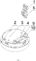
FIG.1 is a schematic structural diagram of a down lamp of the present invention, with mounting bases removed. -
FIG.2 is a partial exploded view of the down lamp of the present invention, with the mounting bases removed. -
FIG.3 is an exploded view of a terminal cap and a wiring terminal in the down lamp of the present invention. -
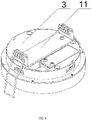
FIG.4 is a schematic structural diagram of matching of the down lamp of the present invention and a first mounting base. -
FIG. 5 is an exploded view of matching of the down lamp of the present invention and the first mounting base. -
FIG.6 is a schematic structural diagram of matching of the down lamp of the present invention and a second mounting base. -
FIG.7 is an exploded view of matching of the down lamp of the present invention and the second mounting base. -
FIG.8 is an enlarged view of area A inFIG.7 . - The present invention will be further described by referring to the embodiments, but is not intended to be limited thereto.
- In an embodiment, a down lamp comprises a housing, mounting bases arranged outside the housing and a
wiring terminal 1 arranged in the housing. Actually, the housing is also internally provided with a control panel, a drive plate, a light source and other structures that are not involved in the technical solution claimed by the present application, therefore, details about these structures are not given below. - The housing comprises a
front shell 2 and arear cap 3. Therear cap 3 has anopening 4 on which aterminal cap 5 is arranged. - The
terminal cap 5 is successively provided with a buckle group, a wire guiding structure 6, awire pressing block 7 and a mounting structure, and the buckle group comprises a columnar positioning structure and two blocky positioning structures, and a clamping slot for embedding in of the columnar positioning structure and two blocky positioning structures is formed in thewiring terminal 1, such that thewiring terminal 1 and theterminal cap 5 are in buckled connection. - The wire guiding structure 6 comprises two guide plates. A connecting wire extending out from the opening of the
wiring terminal 1 is guided by the two guide plates. - The mounting structure refers to two screw mounting holes. The
terminal cap 5 is locked on therear cap 3 via screws. - The wire pressing
block 7 is arranged between the two screw mounting holes, mainly for tightly pressing the guided connecting wire. - The opening 4 of the
rear cap 3 is provided with asupport rib 9 and aslot 10 for insertion of an insertion piece 8 that is arranged on theterminal cap 5. Therefore, when theterminal cap 5 needs to be mounted on therear cap 3, the insertion piece 8 on theterminal cap 5 is inserted into theslot 10, next theterminal cap 5 is integrally placed in theopening 4 and supported by thesupport rib 9, after that, theterminal cap 5 is completely locked on therear cap 3 via screws so as to complete mounting. During disassembly, screws are unscrewed, and then theterminal cap 5 is conveniently taken out, thus being convenient to assemble and dissemble. - The mounting bases comprise a
first mounting base 11 and asecond mounting base 12, and thefirst mounting base 11 comprises amounting bracket 19 andspring buckles 20 at two sides of themounting bracket 19. Two screw mounting holes are formed in the middle of themounting bracket 19. Another screw mounting hole is also formed in the corresponding location of therear cap 3. Themounting bracket 19 is mounted on therear cap 3 viascrews 13. After thefirst mounting base 11 is mounted on therear cap 3, the down lamp can be directly and integrally mounted in an embedded-in manner. - The
second mounting base 12 comprises a base body and a lug arranged in the base body. A clampingslot 14 is provided on the periphery of therear cap 3. The clampingslot 14 is provided with agap 15 for stretching in of the limiting lug at one side, and apositioning bar 16 and astop block 21 at the other side. The lug is embedded in theclamping slot 14 and then clamped between the positioningbar 16 and thestop block 21. One side of thepositioning bar 16 distal to thegap 15 is provided with asubsidiary slot 17 of which the portion proximal to thepositioning bar 16 has arecess 18. The base body of the second mountingbase 12 and therear cap 3 are in rotary buckling. After the second mountingbase 12 is mounted on therear cap 3, the whole down lamp can be directly mounted. - It should be noted that, the above embodiments are merely illustrative, rather than restrictive, for the technical solution of the present invention.
-
- 1
- wiring terminal
- 2
- front shell
- 3
- rear cap
- 4
- opening
- 5
- terminal cap
- 6
- wire guiding structure
- 7
- wire pressing block
- 8
- insertion piece
- 9
- supporting rib
- 10
- slot
- 11
- first mounting base
- 12
- second mounting base
- 13
- screw
- 14
- clamping slot
- 15
- gap
- 16
- positioning bar
- 17
- subsidiary slot
- 18
- recess
- 19
- mounting bracket
- 20
- spring buckle
- 21
- stop block.
Claims (7)
- A down lamp, comprisinga housing and a wiring terminal (1) disposed in the housing, whereinthe housing comprises a front shell (2) and a rear cap (3),the rear cap (3) has an opening (4) at a location corresponding to the wiring terminal (1) and the opening (4) is provided with a terminal cap (5) that is matched with the opening and is in detachable connection with the rear cap (3),the down lamp further comprising:a first mounting base (11) connected to the rear cap (3) for embedded-in mounting of the down lamp, anda second mounting base (12) detachably connected to the rear cap (3) for surface mounting of the down lamp, whereinthe first mounting base (11) is detachably connected to the rear cap (3) through screws, and the second mounting base (12) and the rear cap (3) are in rotary buckling,characterized in thatthe rotary buckling between the second mounting base (12) and the rear cap (3) is such that there is a clamping slot (14) in the rear cap (3), that a lug matched with the clamping slot (14) is disposed on the second mounting base (12), and that the clamping slot (14) is provided with a gap (15) for stretching in of a limiting lug at one side, whereinthe clamping slot (14) is provided with a positioning bar (16) for clamping the limiting lug into the clamping slot (14) at the other side.
- The down lamp of claim 1, wherein one side of the positioning bar (16) far away from the gap (15) is provided with a subsidiary slot (17), and the portion of the subsidiary slot (17) proximal to the positioning bar (16) is provided with a recess (18).
- The down lamp of claim 1 or 2, wherein the wiring terminal (1) and the terminal cap (5) are in detachable connection.
- The down lamp of claim 3, wherein the terminal cap (5) and the wiring terminal (1) are in buckling connection.
- The down lamp of any of the preceding claims, wherein the terminal cap (5) is provided with a wire guiding structure (6) for guiding a connecting wire extending out from the wiring terminal (1).
- The down lamp of any of the preceding claims, wherein the terminal cap (5) is provided with a wire pressing block (7) for tightly pressing a connecting wire extending out from the wiring terminal.
- The down lamp of any of the preceding claims, wherein the terminal cap (5) is provided with an insertion piece (8), and the opening of the rear cap (3) has a supporting rib (9) and a slot for insertion (10) of the insertion piece (8).
Applications Claiming Priority (1)
| Application Number | Priority Date | Filing Date | Title |
|---|---|---|---|
| CN201910705108.3A CN110332486A (en) | 2019-08-01 | 2019-08-01 | Downlight |
Publications (2)
| Publication Number | Publication Date |
|---|---|
| EP3771860A1 EP3771860A1 (en) | 2021-02-03 |
| EP3771860B1 true EP3771860B1 (en) | 2022-11-02 |
Family
ID=68148292
Family Applications (1)
| Application Number | Title | Priority Date | Filing Date |
|---|---|---|---|
| EP20177025.2A Active EP3771860B1 (en) | 2019-08-01 | 2020-05-28 | Down lamp |
Country Status (3)
| Country | Link |
|---|---|
| US (1) | US11143367B2 (en) |
| EP (1) | EP3771860B1 (en) |
| CN (1) | CN110332486A (en) |
Families Citing this family (5)
| Publication number | Priority date | Publication date | Assignee | Title |
|---|---|---|---|---|
| CN208139045U (en) * | 2018-05-29 | 2018-11-23 | 苏州欧普照明有限公司 | A kind of lighting device |
| EP3985301A1 (en) * | 2020-10-15 | 2022-04-20 | Signify Holding B.V. | Downlight unit and assembly method |
| NL2027116B1 (en) * | 2020-12-15 | 2022-07-08 | Schreder Sa | Luminaire head with a removable cap |
| CN115285485A (en) * | 2022-07-11 | 2022-11-04 | 横店集团得邦照明股份有限公司 | Multi-carton-loading inner lining of conventional LED (light emitting diode) tube lamp and implementation method thereof |
| CN121532597A (en) * | 2023-07-20 | 2026-02-13 | 昕诺飞控股有限公司 | Recessed Lighting Fixture Rotation |
Family Cites Families (21)
| Publication number | Priority date | Publication date | Assignee | Title |
|---|---|---|---|---|
| US5738436A (en) * | 1996-09-17 | 1998-04-14 | M.G. Products, Inc. | Modular lighting fixture |
| FR2819949A1 (en) * | 2001-01-23 | 2002-07-26 | Koninkl Philips Electronics Nv | ARRANGEMENT OF AN ELECTRICAL CONNECTION DEVICE OF A BUILT-IN LUMINAIRE |
| DE102004003105A1 (en) * | 2004-01-21 | 2005-08-11 | Zumtobel Staff Gmbh | Lighting housing or light with housing has opening with lid for easy assembly fitted in the wall and connecting elements fitted inside at the edge of the opening and accessible when opening lid |
| US8217381B2 (en) * | 2004-06-04 | 2012-07-10 | The Board Of Trustees Of The University Of Illinois | Controlled buckling structures in semiconductor interconnects and nanomembranes for stretchable electronics |
| CN102022682B (en) * | 2010-12-07 | 2012-06-27 | 上海亮硕光电子科技有限公司 | LED (Light-Emitting Diode) embedded barrel lamp |
| DE202010016643U1 (en) * | 2010-12-14 | 2011-02-17 | Teamwin Opto-Electronics Co., Ltd. | Multifunctional chandelier |
| DE202011051252U1 (en) * | 2011-09-09 | 2012-12-10 | Zumtobel Lighting Gmbh | Damp-proof luminaire with simplified electrical connection |
| US10753558B2 (en) * | 2013-07-05 | 2020-08-25 | DMF, Inc. | Lighting apparatus and methods |
| US10299336B2 (en) * | 2016-02-19 | 2019-05-21 | Eaton Intelligent Power Limited | Configurable lighting system |
| US9820350B2 (en) * | 2016-02-19 | 2017-11-14 | Cooper Technologies Company | Configurable lighting system |
| CN205877920U (en) * | 2016-06-14 | 2017-01-11 | 奥其斯科技股份有限公司 | Tube light |
| CN205991466U (en) * | 2016-08-24 | 2017-03-01 | 吴红梅 | A LED downlight with convenient wiring |
| CN206191375U (en) * | 2016-10-14 | 2017-05-24 | 厦门阳光恩耐照明有限公司 | Novel tube light |
| CN209101057U (en) * | 2016-12-15 | 2019-07-12 | 深圳市亮维光电有限公司 | A downlight with built-in wiring assembly |
| CN206724003U (en) * | 2017-04-01 | 2017-12-08 | 赵杰峰 | A kind of Novel down lamp |
| CN207661588U (en) * | 2017-12-11 | 2018-07-27 | 漳州立达信光电子科技有限公司 | Downlight and lighting device |
| CN208011485U (en) * | 2018-01-19 | 2018-10-26 | 漳州立达信光电子科技有限公司 | a downlight |
| CN108224250A (en) * | 2018-03-05 | 2018-06-29 | 上海海丰照明电器有限公司 | A kind of embedded LED down lamp |
| CN207990400U (en) * | 2018-04-20 | 2018-10-19 | 佛山市钜创照明科技有限公司 | A kind of LED downlight of convertible mounting means |
| CN208268936U (en) * | 2018-04-27 | 2018-12-21 | 深圳市凯信光电有限公司 | A kind of fast-wiring downlight |
| CN108548132A (en) * | 2018-06-15 | 2018-09-18 | 深圳华唐锐照明电器有限公司 | A kind of integrated lamp of tool-free fast-wiring installation |
-
2019
- 2019-08-01 CN CN201910705108.3A patent/CN110332486A/en active Pending
-
2020
- 2020-05-26 US US16/882,761 patent/US11143367B2/en active Active
- 2020-05-28 EP EP20177025.2A patent/EP3771860B1/en active Active
Also Published As
| Publication number | Publication date |
|---|---|
| US20210033251A1 (en) | 2021-02-04 |
| CN110332486A (en) | 2019-10-15 |
| EP3771860A1 (en) | 2021-02-03 |
| US11143367B2 (en) | 2021-10-12 |
Similar Documents
| Publication | Publication Date | Title |
|---|---|---|
| US11143367B2 (en) | Down lamp | |
| US11484810B2 (en) | Accessory of light-sabre type | |
| US8646951B2 (en) | Illuminating apparatus | |
| US20080130206A1 (en) | Attachment and detachment mechanism for portable electronic device | |
| CN105258083A (en) | Power supply box structure, lamp constituted with power supply box structure and quick electric connection method of lamp | |
| US7261446B2 (en) | Light assembly for a vehicle | |
| US6347959B2 (en) | Bracket for attaching interior equipment | |
| EP1931043A2 (en) | Attachment and detachment mechanism for portable electronic device | |
| CN206694988U (en) | Ceiling lamp | |
| CN106969300A (en) | Ceiling lamp | |
| JP3867040B2 (en) | Lamp socket and lighting apparatus using the same | |
| EP3980684A1 (en) | Lighting device for vehicle headlamps | |
| JPH09250520A (en) | Enclosure fixing structure | |
| US20090103316A1 (en) | Chassis for a light source unit, a light source unit including the chassis, and a display device including the chassis | |
| JP3238290U (en) | Ceiling light | |
| JP6407317B2 (en) | Light source unit and lighting device | |
| JP4159411B2 (en) | Lamp holding device for light source for endoscope | |
| CN223985110U (en) | A magnetic resonance lighting device and magnetic resonance equipment | |
| JP2006201741A (en) | Plasma display device | |
| CN213787497U (en) | Ultrasound equipment | |
| CN212776963U (en) | Lighting components | |
| CN118867750A (en) | A sterile electrical connection structure for a surgical manipulator | |
| JP2004161131A (en) | Vehicle interior lighting system | |
| KR200285370Y1 (en) | Fluorescent Lamp Socket | |
| JP2005014768A (en) | Vehicular speaker device |
Legal Events
| Date | Code | Title | Description |
|---|---|---|---|
| PUAI | Public reference made under article 153(3) epc to a published international application that has entered the european phase |
Free format text: ORIGINAL CODE: 0009012 |
|
| STAA | Information on the status of an ep patent application or granted ep patent |
Free format text: STATUS: THE APPLICATION HAS BEEN PUBLISHED |
|
| AK | Designated contracting states |
Kind code of ref document: A1 Designated state(s): AL AT BE BG CH CY CZ DE DK EE ES FI FR GB GR HR HU IE IS IT LI LT LU LV MC MK MT NL NO PL PT RO RS SE SI SK SM TR |
|
| AX | Request for extension of the european patent |
Extension state: BA ME |
|
| STAA | Information on the status of an ep patent application or granted ep patent |
Free format text: STATUS: REQUEST FOR EXAMINATION WAS MADE |
|
| 17P | Request for examination filed |
Effective date: 20210802 |
|
| RBV | Designated contracting states (corrected) |
Designated state(s): AL AT BE BG CH CY CZ DE DK EE ES FI FR GB GR HR HU IE IS IT LI LT LU LV MC MK MT NL NO PL PT RO RS SE SI SK SM TR |
|
| GRAP | Despatch of communication of intention to grant a patent |
Free format text: ORIGINAL CODE: EPIDOSNIGR1 |
|
| STAA | Information on the status of an ep patent application or granted ep patent |
Free format text: STATUS: GRANT OF PATENT IS INTENDED |
|
| RIC1 | Information provided on ipc code assigned before grant |
Ipc: F21V 17/10 20060101ALN20220524BHEP Ipc: F21V 21/04 20060101ALN20220524BHEP Ipc: F21V 21/03 20060101ALN20220524BHEP Ipc: F21S 8/02 20060101ALN20220524BHEP Ipc: F21S 8/04 20060101ALI20220524BHEP Ipc: F21V 15/01 20060101ALI20220524BHEP Ipc: F21V 23/06 20060101AFI20220524BHEP |
|
| INTG | Intention to grant announced |
Effective date: 20220627 |
|
| GRAS | Grant fee paid |
Free format text: ORIGINAL CODE: EPIDOSNIGR3 |
|
| RIN1 | Information on inventor provided before grant (corrected) |
Inventor name: YU, XIANGJUN Inventor name: YUAN, LIU |
|
| GRAA | (expected) grant |
Free format text: ORIGINAL CODE: 0009210 |
|
| STAA | Information on the status of an ep patent application or granted ep patent |
Free format text: STATUS: THE PATENT HAS BEEN GRANTED |
|
| AK | Designated contracting states |
Kind code of ref document: B1 Designated state(s): AL AT BE BG CH CY CZ DE DK EE ES FI FR GB GR HR HU IE IS IT LI LT LU LV MC MK MT NL NO PL PT RO RS SE SI SK SM TR |
|
| REG | Reference to a national code |
Ref country code: GB Ref legal event code: FG4D |
|
| REG | Reference to a national code |
Ref country code: CH Ref legal event code: EP Ref country code: AT Ref legal event code: REF Ref document number: 1528988 Country of ref document: AT Kind code of ref document: T Effective date: 20221115 |
|
| REG | Reference to a national code |
Ref country code: DE Ref legal event code: R096 Ref document number: 602020005979 Country of ref document: DE |
|
| REG | Reference to a national code |
Ref country code: IE Ref legal event code: FG4D |
|
| REG | Reference to a national code |
Ref country code: LT Ref legal event code: MG9D |
|
| REG | Reference to a national code |
Ref country code: NL Ref legal event code: MP Effective date: 20221102 |
|
| REG | Reference to a national code |
Ref country code: AT Ref legal event code: MK05 Ref document number: 1528988 Country of ref document: AT Kind code of ref document: T Effective date: 20221102 |
|
| PG25 | Lapsed in a contracting state [announced via postgrant information from national office to epo] |
Ref country code: SE Free format text: LAPSE BECAUSE OF FAILURE TO SUBMIT A TRANSLATION OF THE DESCRIPTION OR TO PAY THE FEE WITHIN THE PRESCRIBED TIME-LIMIT Effective date: 20221102 Ref country code: PT Free format text: LAPSE BECAUSE OF FAILURE TO SUBMIT A TRANSLATION OF THE DESCRIPTION OR TO PAY THE FEE WITHIN THE PRESCRIBED TIME-LIMIT Effective date: 20230302 Ref country code: NO Free format text: LAPSE BECAUSE OF FAILURE TO SUBMIT A TRANSLATION OF THE DESCRIPTION OR TO PAY THE FEE WITHIN THE PRESCRIBED TIME-LIMIT Effective date: 20230202 Ref country code: LT Free format text: LAPSE BECAUSE OF FAILURE TO SUBMIT A TRANSLATION OF THE DESCRIPTION OR TO PAY THE FEE WITHIN THE PRESCRIBED TIME-LIMIT Effective date: 20221102 Ref country code: FI Free format text: LAPSE BECAUSE OF FAILURE TO SUBMIT A TRANSLATION OF THE DESCRIPTION OR TO PAY THE FEE WITHIN THE PRESCRIBED TIME-LIMIT Effective date: 20221102 Ref country code: ES Free format text: LAPSE BECAUSE OF FAILURE TO SUBMIT A TRANSLATION OF THE DESCRIPTION OR TO PAY THE FEE WITHIN THE PRESCRIBED TIME-LIMIT Effective date: 20221102 Ref country code: AT Free format text: LAPSE BECAUSE OF FAILURE TO SUBMIT A TRANSLATION OF THE DESCRIPTION OR TO PAY THE FEE WITHIN THE PRESCRIBED TIME-LIMIT Effective date: 20221102 |
|
| PG25 | Lapsed in a contracting state [announced via postgrant information from national office to epo] |
Ref country code: RS Free format text: LAPSE BECAUSE OF FAILURE TO SUBMIT A TRANSLATION OF THE DESCRIPTION OR TO PAY THE FEE WITHIN THE PRESCRIBED TIME-LIMIT Effective date: 20221102 Ref country code: PL Free format text: LAPSE BECAUSE OF FAILURE TO SUBMIT A TRANSLATION OF THE DESCRIPTION OR TO PAY THE FEE WITHIN THE PRESCRIBED TIME-LIMIT Effective date: 20221102 Ref country code: LV Free format text: LAPSE BECAUSE OF FAILURE TO SUBMIT A TRANSLATION OF THE DESCRIPTION OR TO PAY THE FEE WITHIN THE PRESCRIBED TIME-LIMIT Effective date: 20221102 Ref country code: IS Free format text: LAPSE BECAUSE OF FAILURE TO SUBMIT A TRANSLATION OF THE DESCRIPTION OR TO PAY THE FEE WITHIN THE PRESCRIBED TIME-LIMIT Effective date: 20230302 Ref country code: HR Free format text: LAPSE BECAUSE OF FAILURE TO SUBMIT A TRANSLATION OF THE DESCRIPTION OR TO PAY THE FEE WITHIN THE PRESCRIBED TIME-LIMIT Effective date: 20221102 Ref country code: GR Free format text: LAPSE BECAUSE OF FAILURE TO SUBMIT A TRANSLATION OF THE DESCRIPTION OR TO PAY THE FEE WITHIN THE PRESCRIBED TIME-LIMIT Effective date: 20230203 |
|
| PG25 | Lapsed in a contracting state [announced via postgrant information from national office to epo] |
Ref country code: NL Free format text: LAPSE BECAUSE OF FAILURE TO SUBMIT A TRANSLATION OF THE DESCRIPTION OR TO PAY THE FEE WITHIN THE PRESCRIBED TIME-LIMIT Effective date: 20221102 |
|
| PG25 | Lapsed in a contracting state [announced via postgrant information from national office to epo] |
Ref country code: SM Free format text: LAPSE BECAUSE OF FAILURE TO SUBMIT A TRANSLATION OF THE DESCRIPTION OR TO PAY THE FEE WITHIN THE PRESCRIBED TIME-LIMIT Effective date: 20221102 Ref country code: RO Free format text: LAPSE BECAUSE OF FAILURE TO SUBMIT A TRANSLATION OF THE DESCRIPTION OR TO PAY THE FEE WITHIN THE PRESCRIBED TIME-LIMIT Effective date: 20221102 Ref country code: EE Free format text: LAPSE BECAUSE OF FAILURE TO SUBMIT A TRANSLATION OF THE DESCRIPTION OR TO PAY THE FEE WITHIN THE PRESCRIBED TIME-LIMIT Effective date: 20221102 Ref country code: DK Free format text: LAPSE BECAUSE OF FAILURE TO SUBMIT A TRANSLATION OF THE DESCRIPTION OR TO PAY THE FEE WITHIN THE PRESCRIBED TIME-LIMIT Effective date: 20221102 Ref country code: CZ Free format text: LAPSE BECAUSE OF FAILURE TO SUBMIT A TRANSLATION OF THE DESCRIPTION OR TO PAY THE FEE WITHIN THE PRESCRIBED TIME-LIMIT Effective date: 20221102 |
|
| REG | Reference to a national code |
Ref country code: DE Ref legal event code: R097 Ref document number: 602020005979 Country of ref document: DE |
|
| PG25 | Lapsed in a contracting state [announced via postgrant information from national office to epo] |
Ref country code: SK Free format text: LAPSE BECAUSE OF FAILURE TO SUBMIT A TRANSLATION OF THE DESCRIPTION OR TO PAY THE FEE WITHIN THE PRESCRIBED TIME-LIMIT Effective date: 20221102 Ref country code: AL Free format text: LAPSE BECAUSE OF FAILURE TO SUBMIT A TRANSLATION OF THE DESCRIPTION OR TO PAY THE FEE WITHIN THE PRESCRIBED TIME-LIMIT Effective date: 20221102 |
|
| PLBE | No opposition filed within time limit |
Free format text: ORIGINAL CODE: 0009261 |
|
| STAA | Information on the status of an ep patent application or granted ep patent |
Free format text: STATUS: NO OPPOSITION FILED WITHIN TIME LIMIT |
|
| 26N | No opposition filed |
Effective date: 20230803 |
|
| PG25 | Lapsed in a contracting state [announced via postgrant information from national office to epo] |
Ref country code: SI Free format text: LAPSE BECAUSE OF FAILURE TO SUBMIT A TRANSLATION OF THE DESCRIPTION OR TO PAY THE FEE WITHIN THE PRESCRIBED TIME-LIMIT Effective date: 20221102 |
|
| PG25 | Lapsed in a contracting state [announced via postgrant information from national office to epo] |
Ref country code: IT Free format text: LAPSE BECAUSE OF FAILURE TO SUBMIT A TRANSLATION OF THE DESCRIPTION OR TO PAY THE FEE WITHIN THE PRESCRIBED TIME-LIMIT Effective date: 20221102 |
|
| PGFP | Annual fee paid to national office [announced via postgrant information from national office to epo] |
Ref country code: MC Payment date: 20240423 Year of fee payment: 5 |
|
| PG25 | Lapsed in a contracting state [announced via postgrant information from national office to epo] |
Ref country code: BG Free format text: LAPSE BECAUSE OF FAILURE TO SUBMIT A TRANSLATION OF THE DESCRIPTION OR TO PAY THE FEE WITHIN THE PRESCRIBED TIME-LIMIT Effective date: 20221102 |
|
| PG25 | Lapsed in a contracting state [announced via postgrant information from national office to epo] |
Ref country code: BG Free format text: LAPSE BECAUSE OF FAILURE TO SUBMIT A TRANSLATION OF THE DESCRIPTION OR TO PAY THE FEE WITHIN THE PRESCRIBED TIME-LIMIT Effective date: 20221102 |
|
| PGFP | Annual fee paid to national office [announced via postgrant information from national office to epo] |
Ref country code: LU Payment date: 20250429 Year of fee payment: 6 |
|
| PGFP | Annual fee paid to national office [announced via postgrant information from national office to epo] |
Ref country code: DE Payment date: 20250513 Year of fee payment: 6 |
|
| PGFP | Annual fee paid to national office [announced via postgrant information from national office to epo] |
Ref country code: BE Payment date: 20250527 Year of fee payment: 6 |
|
| PGFP | Annual fee paid to national office [announced via postgrant information from national office to epo] |
Ref country code: FR Payment date: 20250530 Year of fee payment: 6 |
|
| PGFP | Annual fee paid to national office [announced via postgrant information from national office to epo] |
Ref country code: CH Payment date: 20250601 Year of fee payment: 6 |
|
| PG25 | Lapsed in a contracting state [announced via postgrant information from national office to epo] |
Ref country code: CY Free format text: LAPSE BECAUSE OF FAILURE TO SUBMIT A TRANSLATION OF THE DESCRIPTION OR TO PAY THE FEE WITHIN THE PRESCRIBED TIME-LIMIT; INVALID AB INITIO Effective date: 20200528 |
|
| PGFP | Annual fee paid to national office [announced via postgrant information from national office to epo] |
Ref country code: IE Payment date: 20250422 Year of fee payment: 6 |
|
| PG25 | Lapsed in a contracting state [announced via postgrant information from national office to epo] |
Ref country code: HU Free format text: LAPSE BECAUSE OF FAILURE TO SUBMIT A TRANSLATION OF THE DESCRIPTION OR TO PAY THE FEE WITHIN THE PRESCRIBED TIME-LIMIT; INVALID AB INITIO Effective date: 20200528 |
|
| PG25 | Lapsed in a contracting state [announced via postgrant information from national office to epo] |
Ref country code: TR Free format text: LAPSE BECAUSE OF FAILURE TO SUBMIT A TRANSLATION OF THE DESCRIPTION OR TO PAY THE FEE WITHIN THE PRESCRIBED TIME-LIMIT Effective date: 20221102 |
|
| PG25 | Lapsed in a contracting state [announced via postgrant information from national office to epo] |
Ref country code: MC Free format text: LAPSE BECAUSE OF NON-PAYMENT OF DUE FEES Effective date: 20250602 |
|
| PGFP | Annual fee paid to national office [announced via postgrant information from national office to epo] |
Ref country code: GB Payment date: 20260306 Year of fee payment: 7 |