EP3771852A1 - Epicyclic handwheel for operating a valve with means for indication of the operating parameters - Google Patents
Epicyclic handwheel for operating a valve with means for indication of the operating parameters Download PDFInfo
- Publication number
- EP3771852A1 EP3771852A1 EP20187936.8A EP20187936A EP3771852A1 EP 3771852 A1 EP3771852 A1 EP 3771852A1 EP 20187936 A EP20187936 A EP 20187936A EP 3771852 A1 EP3771852 A1 EP 3771852A1
- Authority
- EP
- European Patent Office
- Prior art keywords
- control knob
- valve
- handwheel
- epicyclic
- sun gear
- Prior art date
- Legal status (The legal status is an assumption and is not a legal conclusion. Google has not performed a legal analysis and makes no representation as to the accuracy of the status listed.)
- Granted
Links
- 230000005540 biological transmission Effects 0.000 claims abstract description 8
- 239000012530 fluid Substances 0.000 claims description 13
- 238000003780 insertion Methods 0.000 claims description 7
- 230000037431 insertion Effects 0.000 claims description 7
- 230000000295 complement effect Effects 0.000 claims description 6
- 230000001419 dependent effect Effects 0.000 claims description 4
- 238000004519 manufacturing process Methods 0.000 claims description 4
- 238000006243 chemical reaction Methods 0.000 claims description 3
- 238000000034 method Methods 0.000 claims description 2
- 230000000875 corresponding effect Effects 0.000 description 17
- 238000009434 installation Methods 0.000 description 3
- 230000002596 correlated effect Effects 0.000 description 2
- 238000006073 displacement reaction Methods 0.000 description 2
- 238000005259 measurement Methods 0.000 description 2
- 230000002441 reversible effect Effects 0.000 description 2
- 230000006835 compression Effects 0.000 description 1
- 238000007906 compression Methods 0.000 description 1
- 238000012544 monitoring process Methods 0.000 description 1
- XLYOFNOQVPJJNP-UHFFFAOYSA-N water Substances O XLYOFNOQVPJJNP-UHFFFAOYSA-N 0.000 description 1
Images

Classifications
-
- F—MECHANICAL ENGINEERING; LIGHTING; HEATING; WEAPONS; BLASTING
- F16—ENGINEERING ELEMENTS AND UNITS; GENERAL MEASURES FOR PRODUCING AND MAINTAINING EFFECTIVE FUNCTIONING OF MACHINES OR INSTALLATIONS; THERMAL INSULATION IN GENERAL
- F16K—VALVES; TAPS; COCKS; ACTUATING-FLOATS; DEVICES FOR VENTING OR AERATING
- F16K37/00—Special means in or on valves or other cut-off apparatus for indicating or recording operation thereof, or for enabling an alarm to be given
- F16K37/0008—Mechanical means
- F16K37/0016—Mechanical means having a graduated scale
-
- F—MECHANICAL ENGINEERING; LIGHTING; HEATING; WEAPONS; BLASTING
- F16—ENGINEERING ELEMENTS AND UNITS; GENERAL MEASURES FOR PRODUCING AND MAINTAINING EFFECTIVE FUNCTIONING OF MACHINES OR INSTALLATIONS; THERMAL INSULATION IN GENERAL
- F16K—VALVES; TAPS; COCKS; ACTUATING-FLOATS; DEVICES FOR VENTING OR AERATING
- F16K31/00—Actuating devices; Operating means; Releasing devices
- F16K31/44—Mechanical actuating means
- F16K31/53—Mechanical actuating means with toothed gearing
-
- F—MECHANICAL ENGINEERING; LIGHTING; HEATING; WEAPONS; BLASTING
- F16—ENGINEERING ELEMENTS AND UNITS; GENERAL MEASURES FOR PRODUCING AND MAINTAINING EFFECTIVE FUNCTIONING OF MACHINES OR INSTALLATIONS; THERMAL INSULATION IN GENERAL
- F16K—VALVES; TAPS; COCKS; ACTUATING-FLOATS; DEVICES FOR VENTING OR AERATING
- F16K31/00—Actuating devices; Operating means; Releasing devices
- F16K31/44—Mechanical actuating means
- F16K31/60—Handles
-
- F—MECHANICAL ENGINEERING; LIGHTING; HEATING; WEAPONS; BLASTING
- F16—ENGINEERING ELEMENTS AND UNITS; GENERAL MEASURES FOR PRODUCING AND MAINTAINING EFFECTIVE FUNCTIONING OF MACHINES OR INSTALLATIONS; THERMAL INSULATION IN GENERAL
- F16K—VALVES; TAPS; COCKS; ACTUATING-FLOATS; DEVICES FOR VENTING OR AERATING
- F16K35/00—Means to prevent accidental or unauthorised actuation
- F16K35/02—Means to prevent accidental or unauthorised actuation to be locked or disconnected by means of a pushing or pulling action
- F16K35/027—Means to prevent accidental or unauthorised actuation to be locked or disconnected by means of a pushing or pulling action the locking mechanism being actuated by pushing or pulling the valve actuator, the valve actuator being rotated subsequently to bring the valve closure element in the desired position
-
- F—MECHANICAL ENGINEERING; LIGHTING; HEATING; WEAPONS; BLASTING
- F16—ENGINEERING ELEMENTS AND UNITS; GENERAL MEASURES FOR PRODUCING AND MAINTAINING EFFECTIVE FUNCTIONING OF MACHINES OR INSTALLATIONS; THERMAL INSULATION IN GENERAL
- F16K—VALVES; TAPS; COCKS; ACTUATING-FLOATS; DEVICES FOR VENTING OR AERATING
- F16K37/00—Special means in or on valves or other cut-off apparatus for indicating or recording operation thereof, or for enabling an alarm to be given
- F16K37/0058—Optical means, e.g. light transmission, observation ports
-
- G—PHYSICS
- G05—CONTROLLING; REGULATING
- G05G—CONTROL DEVICES OR SYSTEMS INSOFAR AS CHARACTERISED BY MECHANICAL FEATURES ONLY
- G05G1/00—Controlling members, e.g. knobs or handles; Assemblies or arrangements thereof; Indicating position of controlling members
- G05G1/015—Arrangements for indicating the position of a controlling member
-
- G—PHYSICS
- G05—CONTROLLING; REGULATING
- G05G—CONTROL DEVICES OR SYSTEMS INSOFAR AS CHARACTERISED BY MECHANICAL FEATURES ONLY
- G05G1/00—Controlling members, e.g. knobs or handles; Assemblies or arrangements thereof; Indicating position of controlling members
- G05G1/08—Controlling members for hand actuation by rotary movement, e.g. hand wheels
Definitions
- the present invention relates to an epicyclically operated handwheel for operating a valve and a valve unit comprising such a handwheel.
- the handwheel according to the invention is in particular applicable to quarter-turn valves, for example butterfly valves, but also to ball valves and in general all those valves for which a high operating torque is needed in order to open or close them.
- valves for example quarter-turn valves
- the same valves have a valve body which defines a passage for a fluid, and an element for closing the fluid passage, which may be rotated about its axis by means of an actuating shaft, so as to cause opening/closing of the fluid passage.
- the closing element in particular a disc, is configured so as to be arranged with any orientation ranging between zero degrees, corresponding to a closed condition of the fluid passage, and 90 degrees, corresponding to a fully open condition of the fluid passage.
- a particular example of the quarter-turn valve consists of so-called butterfly valves.
- the opening or closing of a valve may be performed and adjusted by suitable means which may comprise a handwheel and which, although performing their function, have some limitations.
- a first problem associated with the known adjustment means for valves of the type described is that they are unable to provide precise and stable adjustment of the valve opening movement, it moreover not being possible to prevent accidental undesirable rotation of the levers or adjustment handwheels.
- a further problem is linked to the impossibility of measuring a number of significant physical parameters for setting and monitoring the fluid-mechanical installation controlled by means of the valve.
- the main significant physical quantities are the flowrate, the pressure and the temperature of the fluid entering and/or exiting the valve.
- the measurement of the pressure and/or the temperature may be performed relatively easily, the same is not true for measurement of the flowrate. It is in fact difficult to obtain a system for measuring the flowrate which has a reasonable cost and is able to satisfy the market requirements. It is therefore desirable to provide a device for adjusting the opening of a valve, in particular a quarter-turn valve, which allows one or more operating parameters of the valve to be determined and adjusted in a precise and easy manner.
- Kv value flow coefficient or Cv in the USA
- the conductivity Kv is defined as the flowrate in cubic metres of water per hour at the temperature of 16°C with a pressure drop of 1 bar across the valve, in the direction of flow of the fluid.
- the technical problem which is posed, therefore, is that of providing a device for adjusting a valve, in particular a quarter-turn valve, which is able to solve or limit one or more of the said problems of the prior art.
- this device should have small dimensions, be easy and inexpensive to produce and assemble and be able to be easily installed at any user location using normal standardized connection means.
- an epicyclic handwheel for a valve in particular a quarter-turn valve, comprising: a control knob which can be rotationally operated about a longitudinal axis; and an epicyclic mechanism for transmission of a rotational movement, comprising:
- This configuration results in numerous advantages including in particular the transmission of high torques from the control knob to an actuating shaft during opening/closing of the valve, while keeping the axial extension of the handwheel extremely compact.
- the handwheel comprises a flat plate arranged between the planet gears and the control knob and rotationally integral with the planet carrier.
- the annular plate has on its front surface, adjacent to the inner surface of the control knob, an indication of the value of at least one operating parameter of the valve; the control knob has in turn at least one window on its front surface which allows the viewing of the operating parameter indicated on the annular plate.
- the indication of the parameter allows viewing, on the front surface of the control knob, of the value of the parameter set by means of rotation of said control knob.
- the annular plate may in particular be rotationally integral with a part of the planet carrier, preferably the support, which during use is rotationally integral with a shaft of the valve, the at least one parameter being in particular a parameter dependent on the degree of rotation of a closing element operated by the valve shaft.
- the indication comprises at least one graduated scale distributed over a suitable angular extension of the annular plate and comprising a plurality of values of the operating parameter.
- the at least one operating parameter preferably comprises an opening angle of the valve and/or a hydraulic conductivity of the valve.
- the indication may also comprise a plurality of graduated scales arranged concentric or in diametrically opposite positions on the annular plate; and/or a plurality of graduated scales for indicating a same parameter, in particular the hydraulic conductivity, which varies depending on the type and/or the size of the valve.
- the at least one window may, depending on the different configurations, have a size such as to allow the simultaneous viewing of a first and at least one further operating parameter.
- at least one further window may be provided for allowing viewing of at least one further parameter.
- a partial covering element of a window of the control knob which may be stably and reversibly connected to the said control knob, may be preferably used to allow the viewing only of indications relating to one or more parameters of interest or relating to the specific valve.
- the planet carrier comprises a support, which has a plurality of pins, which are preferably hollow, each extending parallel to the longitudinal axis towards the control knob and designed to support and act as a rotational pivot for a respective planet gear coaxially mounted on the respective pin.
- the handwheel preferably comprises at least two, preferably three planet gears.
- the support may comprise a coaxial sleeve extending longitudinally from a rear side thereof, preferably configured for engagement with the valve shaft and/or having dimensions suitable for coaxial insertion inside a corresponding hole of the crown wheel.
- the plant carrier may include a cover axially arranged between the planet gears and the control knob so as to limit, in particular lock, the longitudinal position of each planet gear, leaving it free to rotate.
- the cover preferably comprises an annular disc arranged between the support and the control knob so as to limit, in particular lock, the longitudinal axial position of the planet gears, leaving them free to rotate on the respective pin.
- the support and/or the cover in particular the covering disc, has/have a plurality of projecting shoulders extending in the longitudinal direction, preferably with a substantially triangular or trapezoidal form, which give the handwheel a better structural rigidity and durability.
- the cover in particular the covering disc, has an outer annular edge formed as an asymmetrical structure, with a predefined circumferential extension, suitable for cooperating with a corresponding inner seat of the crown wheel, the asymmetrical edge structure and the seat being dimensioned and configured to limit the rotation of the planet carrier with respect to the crown wheel within a certain predefined range of rotation, thus avoiding in particular erroneous settings of the degree of opening of a valve.
- the epicyclic handwheel comprises a mechanism for reversibly locking the rotation of the control knob, comprising first locking means rotationally integral with the control knob and cooperating with second complementary locking means arranged on the crown wheel of the epicyclic mechanism.
- the control knob is movable between at least a first operating position, in which the first locking means engage the second complementary locking means so as to lock rotation of the control knob about the longitudinal axis, and at least one second operating position, in which the first locking means are disengaged from the second locking means, allowing rotation of the control knob.
- the first locking means comprise for example an internal annular toothing of an annular body integral with the control knob and the second locking means may comprise a complementary annular toothing on an outer surface of the crown wheel.
- the control knob in particular may be axially movable in the longitudinal direction with respect to the crown wheel between said first locked operating position and said at least one second operating position.
- one or more thrust springs are arranged between the crown wheel and the control knob so as to keep the control knob at a predefined distance from the crown wheel corresponding to the first operating position.
- the annular plate may also be partially freely to move in the axial direction with respect to the support against the thrusting action of one or more of said springs, so that the plate provides a reaction surface for the springs, which push the plate towards the control knob in the longitudinal direction.
- the invention also relates to a kit according to Claim 17 and a method for the production of a handwheel according to Claim 18.
- Fig. 1 With reference to Fig. 1 , solely for the sake of easier description and without a limiting meaning, the following are assumed: an axial longitudinal direction X-X, parallel to the longitudinal axis x of rotation of a handwheel according to the invention, and a transverse/radial direction Y-Y perpendicular to said longitudinal direction and parallel to a diameter of the handwheel according to the present invention, as well as a front part corresponding to the part of the control knob of the handwheel facing the user during use, and a rear part, opposite to the front part in the axial longitudinal direction X-X and facing, during use, the valve body of a valve operated by means of the handwheel according to the invention.
- the handwheel according to the present invention is in general able to control the opening or closing of a valve comprising: a valve body, which is usually fixed and defines a passage for the flow of a fluid; and an element able to be rotationally operated by means of a valve shaft so as to cause a certain degree of opening or closing of the fluid passage.
- a handwheel 1 comprises a control knob 100 able to be rotationally operated about a longitudinal axis X-X so as to control the opening or closing of a valve.
- the control knob 100 has a front surface 110a and a rear or inner surface 110b, opposite to the front surface in the longitudinal direction X-X.
- the handwheel 1 further comprises an epicyclic mechanism arranged and configured to transmit the rotational movement of the control knob 100 to a shaft for actuating a valve.
- the epicyclic mechanism comprises a sun gear 110, coaxial with the longitudinal axis X-X and integral with the inner surface 110b of the control knob 100.
- the sun gear 110 has an outer circumferential surface provided with suitable toothing 11 and extending in the longitudinal direction over a length suitable for engagement with planet gears described in greater detail below.
- the sun gear 110 is formed as one piece with the control knob 100.
- the epicyclic mechanism further comprises generally a planet carrier 200 configured to be rotationally locked to a shaft for opening/closing the valve.
- the planet carrier 200 has preferably a hole 210a coaxial with the longitudinal axis X-X which has a size and is formed so as to allow the stable connection with the shaft (not shown) of the valve, in particular by means of friction engagement, although other types of connection known in the art are possible for rotationally fixing the shaft to the planet carrier 200.
- the planet carrier 200 is designed to carry a plurality of planet gears 300, in particular at least two and preferably three planet gears 310, designed to rotate with respect to the said planet carrier about a respective axis 310a, 310b, 310c ( Fig. 10 ) parallel, but axially offset with respect to the longitudinal axis X-X of the sun gear 110.
- Each planet gear 310 is arranged on the planet carrier 200 so as to mesh with the outer toothing of the sun gear 110, such that the rotation of the sun gear 110 rotationally operates each of the planet gears 310.
- a coaxial crown wheel 400 is arranged on the outside of the planet carrier 200 and is configured to be rotationally locked to a body of the valve; in particular, the crown wheel 400 may be fixed to the valve body 10 ( Fig. 11 ) by means of suitable fixing means such as fixing screws 401 inserted inside corresponding holes 402 of a rear annular surface of the crown wheel 400, arranged on the axially opposite side of the planet carrier 200 to the control knob 100.
- the crown wheel 400 is provided with an inner annular toothing 410 coaxial with the sun gear 110.
- the planet carrier 200 and the planet gears 310 are arranged inside the crown wheel 400.
- the planet gears 310 each mesh with the inner annular toothing 410 which therefore acts as a fixed element of the epicyclic mechanism for transmission of the movement.
- the general configuration of the epicyclic mechanism described above allows high torques to be transmitted from the control knob to the valve shaft, while keeping the axial extension of the handwheel extremely compact; it is for example possible to obtain a transmission ratio between gear and shaft of 4.4:1 with a longitudinal height of the handwheel 1 equal to only 45 mm.
- a preferred embodiment of the planet carrier 200 comprises a support 210 which is situated close, in the longitudinal direction X-X, to the crown wheel 400 and which has a plurality of pins 211, which are preferably hollow, each extending parallel to the longitudinal axis towards the control knob 100 and designed to support and act as a rotational pivot for a respective planet gear 310 which, when the handwheel is assembled, is coaxially mounted on the respective pin 211.
- the support 210 further comprises preferably a coaxial sleeve 212 extending longitudinally from the rear face of the support 210 and provided with a hole 210a for engagement with the valve shaft.
- the sleeve 212 may have dimensions suitable for coaxial insertion inside a corresponding hole 412 of the crown wheel 400, thus favouring the longitudinal compactness of the handwheel and the correct relative positioning of planet gears and crown wheel 400.
- the support 210 may have a plurality of projecting shoulders 215 extending in the longitudinal direction from a front face of the support, preferably with a substantially triangular or trapezoidal form.
- the shoulders 215 improve the torsional strength of the epicyclic mechanism.
- the planet carrier 200 may further comprise ( Fig. 1 ) a cover 220 which limits and in particular locks the longitudinal/axial position of each planet gear 310 and is arranged between the support 210 and the control knob 110 and is connected to the support 210.
- the cover 220 comprises or is connected to annular plate 221 provided with a plurality of pins 221a projecting from its rear surface and each designed for coaxial insertion into a respective pin 211 of the support 210 which forms the axis of rotation for the respective planet gear 310.
- the annular plate 221 further comprises a hole 221b coaxial with the sun gear 110 and with a size suitable for allowing the passage of the said sun gear.
- the cover 220 may comprise an annular disc 225 of the cover 220 arranged between the support 210 and the annular plate 221.
- the disc 225 may be in particular configured to limit or lock, once the handwheel is assembled, the axial position of the planet gears 310 which remain, however, free to rotate on the respective pin 211.
- the disc 225 may for example comprise a coaxial central hole 225b and a plurality of through-holes 225a, each coaxial with a respective pin 211 of the support 210 and, if present, with the corresponding pin 221a of the annular plate 221.
- sleeves 1225a may be provided (see the variation of embodiment of the second disc 1225 shown in Figs.
- the annular disc 225 preferably has shoulders 225c projecting in the longitudinal direction from its rear surface and suitable for engagement, when the planet carrier 200 is assembled ( Fig. 5 ), with a corresponding shoulder 215 of the support 210.
- Each projecting shoulder 225a will in general have a form, in particular a substantially triangular or trapezoidal form, corresponding to and/or complementing the corresponding shoulder 215 of the support 210.
- the preferred configuration with projecting shoulders arranged on the support 210 and on the disc 225 provides the epicyclic mechanism with further improved torsional strength.
- the cover in particular the disc 225, has an outer annular edge formed as an asymmetrical structure 225c, in particular a circle arc, with a predefined radial extension, designed to cooperate with a corresponding seat 415a ( Figs. 13,14 ) formed in the front part of the inner circumferential surface of the crown wheel 400.
- the asymmetrical edge structure 225d and the seat 415d have dimensions and are configured to limit, when the handwheel is assembled, the rotation of the planet carrier 200 inside the crown wheel 400 within a given predefined rotational range which, for example for quarter-turn valves, may be set to 90°.
- each planet gear 310 is supported on a respective pivot 211 about which it is free to rotate with respect to the support 210 and therefore the entire planet carrier 200.
- Inserting the planet carrier 200 with planet gears 310 coaxially inside the crown wheel 400 and inserting in turn the control knob 100 coaxially on the planet carrier 200 and the crown wheel 400 causes the meshing engagement of the inner toothing 410 of the crown wheel 400 and the toothing of each planet gear 310, which is in turn meshed with the outer toothing of the sun gear 111.
- the handwheel 1 may comprise a mechanism for reversibly locking the rotation of the control knob 100.
- the reversible locking mechanism comprises first locking means 141 rotationally integral with the control knob 100 and configured to cooperate with second locking means 441 arranged on the crown wheel 400 of the epicyclic mechanism so as to lock the rotation of the control knob (with respect to the crown wheel) about the longitudinal axial axis X-X.
- the first locking means 141 comprise an inner annular toothing arranged on the inner surface of an annular body 140 integral during use with the control knob 100, and the annular body 140 may for example be formed as one piece with the control knob 100 or preferably be able to be integrally connected to the control knob 100 by means of complementary connecting means 142,112 for example of the snap-engaging type, in the example shown ( Figs. 1 , 15 ) consisting of teeth 142 projecting in the longitudinal direction from a front edge of the annular body 140 and configured for being inserted by means of snap-engagement inside corresponding seats 112 formed on the inner circumferential surface of the control knob 100.
- the second locking means may comprise annular teeth 141 arranged on the outer circumferential surface of the crown wheel 400 for meshing with the inner toothing 141 integral with the control knob 100 and consequently locking the relative rotation of the control knob 100 and the crown wheel 400 in a first operating position of the handwheel where the rotation of the control knob about the longitudinal axis is locked.
- the control knob 100 is movable between at least a first locked operating position, in which the first locking means engage with the second locking means so as to prevent rotation of the control knob 100 about the longitudinal axis X-X, and at least one second operating position, in which the first locking means are disengaged from the second locking means, allowing rotation of the control knob about the longitudinal axis X-X relative to the crown wheel 400.
- this is performed by configuring the handwheel 1 so that it is possible to perform an axial movement, in the longitudinal direction X-X, of the control knob 100 and of the locking means 141 integral therewith with respect to the crown wheel 400.
- one or more thrust springs 241 are arranged between the crown wheel 400 and the control knob 100 so as to keep the control knob at a predefined distance from the crown wheel 400 corresponding to the first operating position ( Fig. 16a ) in which the teeth 141 engage with the corresponding outer teeth 441 of the circular crown wheel 400.
- each spring 241 may be preferably coaxially inserted inside a respective support pin 211 of the planet carrier 200 so as to push the annular plate 221, the pins 221a of which are coaxially inserted inside the spring 241, towards the control knob 100 in the longitudinal direction X-X.
- the annular plate 221 is, when the handwheel is assembled, partially free to move in the axial direction X-X with respect to the support 210 against the thrusting action of the spring 241.
- the axial displacement of the control knob 100 causes the disengagement of the toothing 141 integral therewith from the outer toothing 441 of the crown wheel 400, allowing the control knob 100 and therefore the sun gear 110 to rotate freely about the longitudinal axis X-X so as to transmit the rotational movement to the planet gears and, via the planet carrier 200, to the valve shaft (not shown).
- the handwheel comprises an annular plate, preferably the already described annular plate 221, arranged between the planet gears 310 and the inner surface 110b of the control knob 100.
- the annular plate 221 is able to rotate integrally with the valve shaft and is for this purpose rotationally integral with a part of the planet carrier 200 rotationally integral with the said shaft, in the examples shown consisting of the planet carrier support 210.
- the annular plate may, as seen above, form part of or be connected to the cover 220 of the planet carrier; according to a variation of an example of embodiment, the annular plate may also consist simply of a top surface of the cover, in particular of the disc 225.
- the annular plate may also be independent of the cover 220 which is an optional element, for as long as the annular plate is rotationally locked to the planet carrier 200 and therefore to the valve shaft.
- the annular plate 221 has on its front surface 221a, adjacent during use to the inner surface of the control knob 100, an indication of the value of at least one operating parameter of the valve; the at least one parameter being dependent on the rotation of the valve shaft.
- the indication may comprise a graduated scale distributed over a suitable angular extension of the annular disc and comprising a plurality of values of the operating parameter.
- a first preferred parameter indicated on the annular disc 221 may be the opening angle ⁇ of the valve ( Fig. 13 ) which is directly dependent on the degree of rotation of the valve shaft and therefore of the planet carrier 200.
- the technical operator will know how to position the disc 221 so that the value of 0 degrees corresponds to a closed position of the valve and so that the graduated scale is oriented in accordance with a rotation of the planet carrier 220 in the direction of opening of the valve; this is particularly easy in the preferred embodiments comprising an asymmetrical structure 225d;415d configured to limit, when the handwheel is assembled, the rotation of the planet carrier 200 inside the crown wheel 400.
- a further preferred parameter which may indicated on the disc or annular plate 221 is the hydraulic conductivity of the valve, known also as the flow factor or Kv value (flow coefficient or Cv in the USA), which is strictly correlated to the type, the size and the opening angle of the valve.
- the further parameter may be indicated on a concentric scale arranged in a position radially on the inside or outside of the first parameter on the disc 221 ( Figs. 12, 13, 14 ) or in a position diametrically opposite to the indication scale of the first parameter a.
- the annular plate 221 may have a plurality of scales for indication of the first or further parameter, in particular the hydraulic conductivity Kv, in the case where this parameter depends for example on the type and/or size of the valve, whereby the handwheel may thus be configured during production so as to indicate the said parameter on different types and sizes of controlled valve.
- control knob 100 has at least one window 130 on its front wall which allows viewing of the current value of the operating parameter indicated on the annular plate 221.
- this window 130 may have dimensions such as to allow simultaneous viewing of the first operating parameter ⁇ and at least one further operating parameter Kv.
- the control knob 100 may have at least one further window 132 designed to allow viewing of the further parameter Kv.
- the handwheel may comprise a removable element 140 for partially covering the further window 132, which may be stably connected to the control knob 100, for example snap-engaged inside a seat formed on its outer front surface, and is configured so as to provide a window 142 which allows viewing of the only one of the multiple scales indicated on the disc 221 for the said further parameter Kv.
- the handwheel may be provided as a kit comprising a plurality of covering elements 140 configured with different windows 142, each designed to allow viewing of only one or more of the multiple scales indicated on the disc 221.
- the handwheel may be easily adapted during installation to the specific type or size of the valve to which it is applied.
- control knob may consist of any element for receiving a rotational movement for operation of the valve, for example also by means of an automated hydraulic or electric actuator.
- the handwheel according to the invention is compact and allows easy operation with advantageous transmission of the rotational movement to the valve shaft for performing opening/closing thereof.
- the locking mechanism prevents the occurrence of accidental undesirable variations in the degree of opening set by means of the handwheel, making also adjustment particularly stable.
- the handwheel is moreover easy to produce and may be easily installed on various types of valves and may also be configured to indicate operating parameters which vary from valve to valve.
Landscapes
- Engineering & Computer Science (AREA)
- General Engineering & Computer Science (AREA)
- Mechanical Engineering (AREA)
- Mechanically-Actuated Valves (AREA)
- Preventing Unauthorised Actuation Of Valves (AREA)
Abstract
Description
- The present invention relates to an epicyclically operated handwheel for operating a valve and a valve unit comprising such a handwheel.
- The handwheel according to the invention is in particular applicable to quarter-turn valves, for example butterfly valves, but also to ball valves and in general all those valves for which a high operating torque is needed in order to open or close them.
- It is known, in the technical sector of valves, for example quarter-turn valves, that the same valves have a valve body which defines a passage for a fluid, and an element for closing the fluid passage, which may be rotated about its axis by means of an actuating shaft, so as to cause opening/closing of the fluid passage. With specific reference to quarter-turn valves, the closing element, in particular a disc, is configured so as to be arranged with any orientation ranging between zero degrees, corresponding to a closed condition of the fluid passage, and 90 degrees, corresponding to a fully open condition of the fluid passage. A particular example of the quarter-turn valve consists of so-called butterfly valves.
- The opening or closing of a valve may be performed and adjusted by suitable means which may comprise a handwheel and which, although performing their function, have some limitations.
- A first problem associated with the known adjustment means for valves of the type described is that they are unable to provide precise and stable adjustment of the valve opening movement, it moreover not being possible to prevent accidental undesirable rotation of the levers or adjustment handwheels.
- A further problem is linked to the impossibility of measuring a number of significant physical parameters for setting and monitoring the fluid-mechanical installation controlled by means of the valve. In the context of the valves described above, the main significant physical quantities are the flowrate, the pressure and the temperature of the fluid entering and/or exiting the valve.
- Although the measurement of the pressure and/or the temperature may be performed relatively easily, the same is not true for measurement of the flowrate. It is in fact difficult to obtain a system for measuring the flowrate which has a reasonable cost and is able to satisfy the market requirements. It is therefore desirable to provide a device for adjusting the opening of a valve, in particular a quarter-turn valve, which allows one or more operating parameters of the valve to be determined and adjusted in a precise and easy manner.
- In connection with this problem it is particularly desirable to be able to adjust and determine the opening angle of the valve and/or one or more fluid-dynamic parameters which allow the flowrate of the fluid through the valve to be calculated.
- An example of such a parameter is the hydraulic conductivity of the valve, also known as the flow factor or Kv value (flow coefficient or Cv in the USA), which is strictly correlated to the type, the size and the opening angle of the closing element of the value and allows the flowrate to be rapidly derived by means of the known formula

- The conductivity Kv is defined as the flowrate in cubic metres of water per hour at the temperature of 16°C with a pressure drop of 1 bar across the valve, in the direction of flow of the fluid.
- The technical problem which is posed, therefore, is that of providing a device for adjusting a valve, in particular a quarter-turn valve, which is able to solve or limit one or more of the said problems of the prior art.
- In connection with this problem it is also required that this device should have small dimensions, be easy and inexpensive to produce and assemble and be able to be easily installed at any user location using normal standardized connection means.
- These results are obtained according to the present invention by an epicyclic handwheel according to Claim 1 and by a valve unit according to Claim 19.
- According to a first aspect the invention therefore relates to an epicyclic handwheel for a valve, in particular a quarter-turn valve, comprising: a control knob which can be rotationally operated about a longitudinal axis; and an epicyclic mechanism for transmission of a rotational movement, comprising:
- -- a sun gear extending along the longitudinal axis and rotationally integral with the control knob;
- -- a planet carrier configured to be rotationally locked to a shaft of the valve;
- -- a crown wheel configured to be rotationally locked to a body of the valve and provided with an internal annular toothing coaxial with the sun gear; and
- -- a plurality of planet gears mounted on the planet carrier and arranged to rotate about a respective axis parallel to the axis of the sun gear and mesh with the said sun gear and with the internal annular toothing of the crown wheel;
- This configuration results in numerous advantages including in particular the transmission of high torques from the control knob to an actuating shaft during opening/closing of the valve, while keeping the axial extension of the handwheel extremely compact.
- According to a particularly advantageous aspect, the handwheel comprises a flat plate arranged between the planet gears and the control knob and rotationally integral with the planet carrier. The annular plate has on its front surface, adjacent to the inner surface of the control knob, an indication of the value of at least one operating parameter of the valve; the control knob has in turn at least one window on its front surface which allows the viewing of the operating parameter indicated on the annular plate. The indication of the parameter allows viewing, on the front surface of the control knob, of the value of the parameter set by means of rotation of said control knob.
- The annular plate may in particular be rotationally integral with a part of the planet carrier, preferably the support, which during use is rotationally integral with a shaft of the valve, the at least one parameter being in particular a parameter dependent on the degree of rotation of a closing element operated by the valve shaft.
- Since the degree of opening or closing of the valve directly depends on the degree of rotation of the actuating shaft and therefore the rotation of the planet carrier, by means of a simple structure a precise and clear indication of one or more operating parameters of the valve is obtained.
- Preferably, the indication comprises at least one graduated scale distributed over a suitable angular extension of the annular plate and comprising a plurality of values of the operating parameter. The at least one operating parameter preferably comprises an opening angle of the valve and/or a hydraulic conductivity of the valve. The indication may also comprise a plurality of graduated scales arranged concentric or in diametrically opposite positions on the annular plate; and/or a plurality of graduated scales for indicating a same parameter, in particular the hydraulic conductivity, which varies depending on the type and/or the size of the valve.
- The at least one window may, depending on the different configurations, have a size such as to allow the simultaneous viewing of a first and at least one further operating parameter. In addition to or alternatively at least one further window may be provided for allowing viewing of at least one further parameter. A partial covering element of a window of the control knob, which may be stably and reversibly connected to the said control knob, may be preferably used to allow the viewing only of indications relating to one or more parameters of interest or relating to the specific valve. Thereby, a same handwheel can be easily adapted, during installation, to the specific kind or size of the valve, with notable improvements as far as production standardization, versatility of application and ease of use are concerned.
- According to a preferred embodiment, the planet carrier comprises a support, which has a plurality of pins, which are preferably hollow, each extending parallel to the longitudinal axis towards the control knob and designed to support and act as a rotational pivot for a respective planet gear coaxially mounted on the respective pin. The handwheel preferably comprises at least two, preferably three planet gears.
- The support may comprise a coaxial sleeve extending longitudinally from a rear side thereof, preferably configured for engagement with the valve shaft and/or having dimensions suitable for coaxial insertion inside a corresponding hole of the crown wheel.
- The plant carrier may include a cover axially arranged between the planet gears and the control knob so as to limit, in particular lock, the longitudinal position of each planet gear, leaving it free to rotate. The cover preferably comprises an annular disc arranged between the support and the control knob so as to limit, in particular lock, the longitudinal axial position of the planet gears, leaving them free to rotate on the respective pin.
- According to a preferred embodiment, the support and/or the cover, in particular the covering disc, has/have a plurality of projecting shoulders extending in the longitudinal direction, preferably with a substantially triangular or trapezoidal form, which give the handwheel a better structural rigidity and durability.
- According to a further preferred aspect, the cover, in particular the covering disc, has an outer annular edge formed as an asymmetrical structure, with a predefined circumferential extension, suitable for cooperating with a corresponding inner seat of the crown wheel, the asymmetrical edge structure and the seat being dimensioned and configured to limit the rotation of the planet carrier with respect to the crown wheel within a certain predefined range of rotation, thus avoiding in particular erroneous settings of the degree of opening of a valve.
- According to a further advantageous aspect of the invention, the epicyclic handwheel comprises a mechanism for reversibly locking the rotation of the control knob, comprising first locking means rotationally integral with the control knob and cooperating with second complementary locking means arranged on the crown wheel of the epicyclic mechanism. The control knob is movable between at least a first operating position, in which the first locking means engage the second complementary locking means so as to lock rotation of the control knob about the longitudinal axis, and at least one second operating position, in which the first locking means are disengaged from the second locking means, allowing rotation of the control knob. According to this preferred solution, with a compact structure undesirable or accidental operation of the control knob is avoided, thereby preventing the valve from being accidentally opened or closed.
- The first locking means comprise for example an internal annular toothing of an annular body integral with the control knob and the second locking means may comprise a complementary annular toothing on an outer surface of the crown wheel. The control knob in particular may be axially movable in the longitudinal direction with respect to the crown wheel between said first locked operating position and said at least one second operating position. Preferably, one or more thrust springs are arranged between the crown wheel and the control knob so as to keep the control knob at a predefined distance from the crown wheel corresponding to the first operating position.
- The annular plate may also be partially freely to move in the axial direction with respect to the support against the thrusting action of one or more of said springs, so that the plate provides a reaction surface for the springs, which push the plate towards the control knob in the longitudinal direction.
- The invention also relates to a kit according to Claim 17 and a method for the production of a handwheel according to Claim 18.
- Further details may be obtained from the following description of non-limiting examples of embodiment of the subject of the present invention, provided with reference to the accompanying drawings, in which:
-
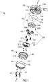
Figure 1 : shows an exploded perspective view, from below, of a first example of embodiment of a handwheel according to the invention -
Figure 2 : shows an exploded perspective view, from above, of the handwheel according toFig. 1 ; -
Figure 3 : shows a front view of the handwheel according toFig. 1 in the assembled condition; -
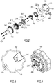
Figure 4 : shows a perspective view, from the rear, of the handwheel according toFig. 1 in the assembled condition; -
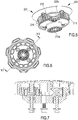
Figure 5 : shows a perspective view of the planet carrier and the planet gears of a handwheel according toFig. 1 in the assembled condition; -
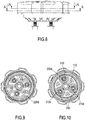
Figure 6 : shows a plan view, from the rear, of the handwheel according to -
Fig. 1 in the assembled condition; -
Figure 7 : shows a view longitudinally sectioned along the plane indicated by VII-VII inFig. 6 ; -
Figure 8 : shows a side view of the handwheel according toFig. 1 in the assembled condition; -
Figure 9 : shows a view cross-sectioned along the radial plane IX-IX ofFig. 8 ; -
Figure 10 : shows a view cross-sectioned along the radial plane X-X ofFig. 9 ; -
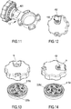
Figure 11 : shows an exploded perspective view, from below, of a first example of embodiment of a handwheel according to the invention fixed to the valve body of a butterfly valve; -
Figure 12 : shows a perspective view, from the front, of a second example of embodiment of the handwheel according to the present invention; -
Figures 13 and 14 : show a partially exploded perspective view of the handwheel according toFig.12 in a respective different adjustment position; -
Figure 15 : shows an exploded perspective view of some parts of a mechanism for reversibly locking the handwheel according toFig. 1 ; -
Figure 16A : shows a longitudinally sectioned view of the handwheel according toFig. 1 , with the locking mechanism in the locked operating position; and -
Figure 16B : shows a longitudinally sectioned view of the handwheel according toFig. 1 , with the locking mechanism in the unlocked operating position. - With reference to
Fig. 1 , solely for the sake of easier description and without a limiting meaning, the following are assumed: an axial longitudinal direction X-X, parallel to the longitudinal axis x of rotation of a handwheel according to the invention, and a transverse/radial direction Y-Y perpendicular to said longitudinal direction and parallel to a diameter of the handwheel according to the present invention, as well as a front part corresponding to the part of the control knob of the handwheel facing the user during use, and a rear part, opposite to the front part in the axial longitudinal direction X-X and facing, during use, the valve body of a valve operated by means of the handwheel according to the invention. - The handwheel according to the present invention is in general able to control the opening or closing of a valve comprising: a valve body, which is usually fixed and defines a passage for the flow of a fluid; and an element able to be rotationally operated by means of a valve shaft so as to cause a certain degree of opening or closing of the fluid passage.
- With reference to
Figs. 1 and2 , a handwheel 1 according to the invention comprises acontrol knob 100 able to be rotationally operated about a longitudinal axis X-X so as to control the opening or closing of a valve. Thecontrol knob 100 has afront surface 110a and a rear orinner surface 110b, opposite to the front surface in the longitudinal direction X-X. - The handwheel 1 further comprises an epicyclic mechanism arranged and configured to transmit the rotational movement of the
control knob 100 to a shaft for actuating a valve. - The epicyclic mechanism comprises a
sun gear 110, coaxial with the longitudinal axis X-X and integral with theinner surface 110b of thecontrol knob 100. - The
sun gear 110 has an outer circumferential surface provided with suitable toothing 11 and extending in the longitudinal direction over a length suitable for engagement with planet gears described in greater detail below. Preferably, thesun gear 110 is formed as one piece with thecontrol knob 100. - The epicyclic mechanism further comprises generally a
planet carrier 200 configured to be rotationally locked to a shaft for opening/closing the valve. For this purpose, theplanet carrier 200 has preferably ahole 210a coaxial with the longitudinal axis X-X which has a size and is formed so as to allow the stable connection with the shaft (not shown) of the valve, in particular by means of friction engagement, although other types of connection known in the art are possible for rotationally fixing the shaft to theplanet carrier 200. - The
planet carrier 200 is designed to carry a plurality of planet gears 300, in particular at least two and preferably threeplanet gears 310, designed to rotate with respect to the said planet carrier about arespective axis Fig. 10 ) parallel, but axially offset with respect to the longitudinal axis X-X of thesun gear 110. - Each
planet gear 310 is arranged on theplanet carrier 200 so as to mesh with the outer toothing of thesun gear 110, such that the rotation of thesun gear 110 rotationally operates each of the planet gears 310. - A
coaxial crown wheel 400 is arranged on the outside of theplanet carrier 200 and is configured to be rotationally locked to a body of the valve; in particular, thecrown wheel 400 may be fixed to the valve body 10 (Fig. 11 ) by means of suitable fixing means such as fixingscrews 401 inserted inside correspondingholes 402 of a rear annular surface of thecrown wheel 400, arranged on the axially opposite side of theplanet carrier 200 to thecontrol knob 100. - The
crown wheel 400 is provided with an innerannular toothing 410 coaxial with thesun gear 110. - Once the handwheel 1 is assembled, the
planet carrier 200 and the planet gears 310 are arranged inside thecrown wheel 400. The planet gears 310 each mesh with the innerannular toothing 410 which therefore acts as a fixed element of the epicyclic mechanism for transmission of the movement. - The general configuration of the epicyclic mechanism described above allows high torques to be transmitted from the control knob to the valve shaft, while keeping the axial extension of the handwheel extremely compact; it is for example possible to obtain a transmission ratio between gear and shaft of 4.4:1 with a longitudinal height of the handwheel 1 equal to only 45 mm.
- With reference still to
Figs. 1-2 and5 , a preferred embodiment of theplanet carrier 200 comprises asupport 210 which is situated close, in the longitudinal direction X-X, to thecrown wheel 400 and which has a plurality ofpins 211, which are preferably hollow, each extending parallel to the longitudinal axis towards thecontrol knob 100 and designed to support and act as a rotational pivot for arespective planet gear 310 which, when the handwheel is assembled, is coaxially mounted on therespective pin 211. - The
support 210 further comprises preferably acoaxial sleeve 212 extending longitudinally from the rear face of thesupport 210 and provided with ahole 210a for engagement with the valve shaft. Advantageously, thesleeve 212 may have dimensions suitable for coaxial insertion inside acorresponding hole 412 of thecrown wheel 400, thus favouring the longitudinal compactness of the handwheel and the correct relative positioning of planet gears andcrown wheel 400. - According to a further preferred aspect, the
support 210 may have a plurality of projectingshoulders 215 extending in the longitudinal direction from a front face of the support, preferably with a substantially triangular or trapezoidal form. Theshoulders 215 improve the torsional strength of the epicyclic mechanism. - The
planet carrier 200 may further comprise (Fig. 1 ) acover 220 which limits and in particular locks the longitudinal/axial position of eachplanet gear 310 and is arranged between thesupport 210 and thecontrol knob 110 and is connected to thesupport 210. - According to a preferred example of embodiment, the
cover 220 comprises or is connected toannular plate 221 provided with a plurality ofpins 221a projecting from its rear surface and each designed for coaxial insertion into arespective pin 211 of thesupport 210 which forms the axis of rotation for therespective planet gear 310. Theannular plate 221 further comprises ahole 221b coaxial with thesun gear 110 and with a size suitable for allowing the passage of the said sun gear. - According to a further preferred aspect, the
cover 220 may comprise anannular disc 225 of thecover 220 arranged between thesupport 210 and theannular plate 221. Thedisc 225 may be in particular configured to limit or lock, once the handwheel is assembled, the axial position of the planet gears 310 which remain, however, free to rotate on therespective pin 211. - The
disc 225 may for example comprise a coaxialcentral hole 225b and a plurality of through-holes 225a, each coaxial with arespective pin 211 of thesupport 210 and, if present, with thecorresponding pin 221a of theannular plate 221. As an alternative to theholes 225a, sleeves 1225a may be provided (see the variation of embodiment of thesecond disc 1225 shown inFigs. 16a,16b ), these being coaxial with the pins 211,221a configured to engage, for example by means of snap-engagement, inside arespective pin 211 and allow the axial insertion, inside them, of arespective pin 221a of theannular plate 221, locking the axial position of the planet gears 310, but preferably leaving theplate 221 free to move over a certain axial distance. - The
annular disc 225 preferably hasshoulders 225c projecting in the longitudinal direction from its rear surface and suitable for engagement, when theplanet carrier 200 is assembled (Fig. 5 ), with acorresponding shoulder 215 of thesupport 210. - Each projecting
shoulder 225a will in general have a form, in particular a substantially triangular or trapezoidal form, corresponding to and/or complementing thecorresponding shoulder 215 of thesupport 210. - The preferred configuration with projecting shoulders arranged on the
support 210 and on thedisc 225 provides the epicyclic mechanism with further improved torsional strength. - According to a further preferred aspect which may be implemented in addition to or independently of the
shoulders 225c, the cover, in particular thedisc 225, has an outer annular edge formed as anasymmetrical structure 225c, in particular a circle arc, with a predefined radial extension, designed to cooperate with a corresponding seat 415a (Figs. 13,14 ) formed in the front part of the inner circumferential surface of thecrown wheel 400. - The
asymmetrical edge structure 225d and theseat 415d have dimensions and are configured to limit, when the handwheel is assembled, the rotation of theplanet carrier 200 inside thecrown wheel 400 within a given predefined rotational range which, for example for quarter-turn valves, may be set to 90°. - As shown in
Figure 5 , when the planet carrier is assembled together with plate fixed rotationally to thesupport 210a andcover disc 225 arranged between thesupport 210 and theannular plate 221, the planet carrier forms a single rotationally integral body, in which eachplanet gear 310 is supported on arespective pivot 211 about which it is free to rotate with respect to thesupport 210 and therefore theentire planet carrier 200. Inserting theplanet carrier 200 withplanet gears 310 coaxially inside thecrown wheel 400 and inserting in turn thecontrol knob 100 coaxially on theplanet carrier 200 and thecrown wheel 400 causes the meshing engagement of theinner toothing 410 of thecrown wheel 400 and the toothing of eachplanet gear 310, which is in turn meshed with the outer toothing of thesun gear 111. - By fixing the shaft of a valve to the
planet carrier 200, in particular by means of friction insertion inside thehole 210a of thesupport 210 and the valve body inside the crown wheel 440, for example by means of fixingscrews 401 inserted inside the correspondingholes 402 of the crown wheel, it is possible to rotationally actuate the valve shaft with respect to the fixed body by rotating thecontrol knob 100 and therefore thesun gear 111 which, via the epicyclic mechanism and in particular the planet gears 310 and thecrown wheel 400, transmits, with advantageous torque, the rotational movement to thesupport 210 of theplanet carrier 200 and from here to the shaft. - According to a further preferred aspect of the invention (
Fig. 15 ), the handwheel 1 according to the present invention may comprise a mechanism for reversibly locking the rotation of thecontrol knob 100. - The reversible locking mechanism comprises first locking means 141 rotationally integral with the
control knob 100 and configured to cooperate with second locking means 441 arranged on thecrown wheel 400 of the epicyclic mechanism so as to lock the rotation of the control knob (with respect to the crown wheel) about the longitudinal axial axis X-X. - According to the preferred example of embodiment shown, the first locking means 141 comprise an inner annular toothing arranged on the inner surface of an
annular body 140 integral during use with thecontrol knob 100, and theannular body 140 may for example be formed as one piece with thecontrol knob 100 or preferably be able to be integrally connected to thecontrol knob 100 by means of complementary connecting means 142,112 for example of the snap-engaging type, in the example shown (Figs. 1 ,15 ) consisting ofteeth 142 projecting in the longitudinal direction from a front edge of theannular body 140 and configured for being inserted by means of snap-engagement inside correspondingseats 112 formed on the inner circumferential surface of thecontrol knob 100. - In accordance with this configuration of the first locking means, the second locking means may comprise
annular teeth 141 arranged on the outer circumferential surface of thecrown wheel 400 for meshing with theinner toothing 141 integral with thecontrol knob 100 and consequently locking the relative rotation of thecontrol knob 100 and thecrown wheel 400 in a first operating position of the handwheel where the rotation of the control knob about the longitudinal axis is locked. - For all the configurations of the handwheel comprising a reversible locking mechanism the
control knob 100 is movable between at least a first locked operating position, in which the first locking means engage with the second locking means so as to prevent rotation of thecontrol knob 100 about the longitudinal axis X-X, and at least one second operating position, in which the first locking means are disengaged from the second locking means, allowing rotation of the control knob about the longitudinal axis X-X relative to thecrown wheel 400. - In the preferred embodiments shown in the drawings, this is performed by configuring the handwheel 1 so that it is possible to perform an axial movement, in the longitudinal direction X-X, of the
control knob 100 and of the locking means 141 integral therewith with respect to thecrown wheel 400. For this purpose, one or more thrust springs 241 are arranged between thecrown wheel 400 and thecontrol knob 100 so as to keep the control knob at a predefined distance from thecrown wheel 400 corresponding to the first operating position (Fig. 16a ) in which theteeth 141 engage with the correspondingouter teeth 441 of thecircular crown wheel 400. In particular, eachspring 241 may be preferably coaxially inserted inside arespective support pin 211 of theplanet carrier 200 so as to push theannular plate 221, thepins 221a of which are coaxially inserted inside thespring 241, towards thecontrol knob 100 in the longitudinal direction X-X. - When the handwheel is assembled, by inserting the
pins 221a of theannular plate 221 inside the hole of therespective pin 211 of thesupport 210, it is possible to connect theannular plate 221 to thesupport 210, so that in particular the pins of theplate 221 guide internally thesprings 241 and the inner base of theplate 221 provides a reaction surface for the said springs 241. - In the preferred embodiment shown, the
annular plate 221 is, when the handwheel is assembled, partially free to move in the axial direction X-X with respect to thesupport 210 against the thrusting action of thespring 241. - As shown in
Figs.16a, 16b , by axially pushing thecontrol knob 100 in the longitudinal direction X-X towards thecrown wheel 400, the inner surface of thecontrol knob 100 pushes against theannular disc 221, causing the compression of thesprings 241 and the displacement of the control knob and thedisc 221 towards thesupport 210 coaxially inserted and axially fixed with respect to the crown wheel 400 (Fig. 16b ). The axial displacement of thecontrol knob 100 causes the disengagement of thetoothing 141 integral therewith from theouter toothing 441 of thecrown wheel 400, allowing thecontrol knob 100 and therefore thesun gear 110 to rotate freely about the longitudinal axis X-X so as to transmit the rotational movement to the planet gears and, via theplanet carrier 200, to the valve shaft (not shown). - With reference still to the preferred embodiments of the handwheel 1 shown in the drawings, a further preferred aspect of the present invention, which may be implemented independently or in combination with the locking mechanism described above, will now be described.
- According to this preferred aspect, the handwheel comprises an annular plate, preferably the already described
annular plate 221, arranged between the planet gears 310 and theinner surface 110b of thecontrol knob 100. Theannular plate 221 is able to rotate integrally with the valve shaft and is for this purpose rotationally integral with a part of theplanet carrier 200 rotationally integral with the said shaft, in the examples shown consisting of theplanet carrier support 210. The annular plate may, as seen above, form part of or be connected to thecover 220 of the planet carrier; according to a variation of an example of embodiment, the annular plate may also consist simply of a top surface of the cover, in particular of thedisc 225. The annular plate may also be independent of thecover 220 which is an optional element, for as long as the annular plate is rotationally locked to theplanet carrier 200 and therefore to the valve shaft. - Advantageously, the
annular plate 221 has on itsfront surface 221a, adjacent during use to the inner surface of thecontrol knob 100, an indication of the value of at least one operating parameter of the valve; the at least one parameter being dependent on the rotation of the valve shaft. In particular, the indication may comprise a graduated scale distributed over a suitable angular extension of the annular disc and comprising a plurality of values of the operating parameter. - A first preferred parameter indicated on the
annular disc 221 may be the opening angle α of the valve (Fig. 13 ) which is directly dependent on the degree of rotation of the valve shaft and therefore of theplanet carrier 200. The technical operator will know how to position thedisc 221 so that the value of 0 degrees corresponds to a closed position of the valve and so that the graduated scale is oriented in accordance with a rotation of theplanet carrier 220 in the direction of opening of the valve; this is particularly easy in the preferred embodiments comprising anasymmetrical structure 225d;415d configured to limit, when the handwheel is assembled, the rotation of theplanet carrier 200 inside thecrown wheel 400. - A further preferred parameter which may indicated on the disc or
annular plate 221 is the hydraulic conductivity of the valve, known also as the flow factor or Kv value (flow coefficient or Cv in the USA), which is strictly correlated to the type, the size and the opening angle of the valve. The further parameter may be indicated on a concentric scale arranged in a position radially on the inside or outside of the first parameter on the disc 221 (Figs. 12, 13, 14 ) or in a position diametrically opposite to the indication scale of the first parameter a. - According to a preferred embodiment, the
annular plate 221 may have a plurality of scales for indication of the first or further parameter, in particular the hydraulic conductivity Kv, in the case where this parameter depends for example on the type and/or size of the valve, whereby the handwheel may thus be configured during production so as to indicate the said parameter on different types and sizes of controlled valve. - In order to allow the visibility of one or more operating parameters indicated on the
annular disc 221, thecontrol knob 100 has at least onewindow 130 on its front wall which allows viewing of the current value of the operating parameter indicated on theannular plate 221. - As shown in
Figures 12, 13, 14 , thiswindow 130 may have dimensions such as to allow simultaneous viewing of the first operating parameter α and at least one further operating parameter Kv. Preferably, as shown inFigs. 2, 3 , thecontrol knob 100 may have at least onefurther window 132 designed to allow viewing of the further parameter Kv. Advantageously, in the case where the further parameter depends for example on the type and/or size of the valve, the handwheel may comprise aremovable element 140 for partially covering thefurther window 132, which may be stably connected to thecontrol knob 100, for example snap-engaged inside a seat formed on its outer front surface, and is configured so as to provide awindow 142 which allows viewing of the only one of the multiple scales indicated on thedisc 221 for the said further parameter Kv. - Advantageously, the handwheel may be provided as a kit comprising a plurality of covering
elements 140 configured withdifferent windows 142, each designed to allow viewing of only one or more of the multiple scales indicated on thedisc 221. In this way, the handwheel may be easily adapted during installation to the specific type or size of the valve to which it is applied. - Although described in the context of embodiments in which the control knob has an ergonomic form for manual operation, it is clear to the person skilled in the art that the control knob may consist of any element for receiving a rotational movement for operation of the valve, for example also by means of an automated hydraulic or electric actuator.
- It is therefore clear how the handwheel according to the invention is compact and allows easy operation with advantageous transmission of the rotational movement to the valve shaft for performing opening/closing thereof.
- The locking mechanism prevents the occurrence of accidental undesirable variations in the degree of opening set by means of the handwheel, making also adjustment particularly stable.
- The possibility of allowing the operator to view one or more operating parameters of the valve makes it easier to perform both adjustment of the valve and subsequent control thereof.
- The handwheel is moreover easy to produce and may be easily installed on various types of valves and may also be configured to indicate operating parameters which vary from valve to valve.
- Although described in connection with a number of embodiments and a number of preferred examples of implementation of the invention, it is understood that the scope of protection of the present patent is defined solely by the claims below.
Claims (19)
- Epicyclic handwheel for a valve, in particular a quarter-turn valve, comprising:- a control knob (100) with an inner surface (110b) and an outer surface (110a) situated opposite each other with respect to a longitudinal axis (X-X), the control knob (100) being rotationally operable about the longitudinal axis;- an epicyclic mechanism for transmission of a rotational movement, comprising:so that by rotationally operating the control knob (100) the rotational movement of the sun gear (111) is transmitted to the planet carrier (200) and therefore to the valve shaft;-- a sun gear (111) extending along the longitudinal axis (X-X) and rotationally integral with the inner surface of the control knob (100);-- a planet carrier (200) configured to be made rotationally integral with a shaft of the valve;-- a crown wheel (400) configured to be made rotationally integral with a body of the valve and provided with an internal annular toothing (41) coaxial with the sun gear (111);-- a plurality of planet gears (310) mounted on the planet carrier (200) and arranged to rotate about a respective axis parallel to the axis of the sun gear (111) and mesh with said sun gear (111) and with the internal annular toothing of the crown wheel;
and further comprising an annular plate (221) arranged between the planet gears (310) and the control knob (100) and rotationally integral with the planet carrier (200), the annular plate (221) having on its front surface (221a), adjacent to the inner surface (110b) of the control knob (100), an indication of the value of at least one operating parameter (a; Kv) of the valve;
and wherein the control knob has at least one window (130;132) on its front surface (110a) which allows viewing of at least one operating parameter (a; Kv) indicated on the annular plate (221). - Epicyclic handwheel according to Claim 1, wherein the at least one operating parameter (a; Kv) comprises a parameter dependent on the degree of rotation of a closing element operated by the valve shaft, preferably an opening angle (a) of the valve and/or a hydraulic conductivity (Kv) of the valve.
- Handwheel according to one of Claims 1 or 2, wherein the indication comprises: a plurality of graduated scales arranged concentric or in diametrically opposite positions on the annular plate (221); and/or a plurality of graduated scales indicating different values of at least one same parameter, in particular the hydraulic conductivity, which is variable depending on the type and/or size of the valve,
And wherein the handwheel further comprises an element (140) for partially covering a window (130; 132) of the control knob (100), which may be stably and reversibly connected to the control knob (100), and is configured to provide a respective reduced size window (142) able to show only one or more of the graduated scales indicated on the annular plate (221). - Handwheel according to one of the preceding claims, wherein one or more graduated scales is/are distributed over a suitable angular extension of the annular plate (221) and comprise a plurality of values of the operating parameter (α; Kv).
- Handwheel according to one of Claims 1 to 4, characterized in that it comprises: at least one window (130), in particular said reduced size window (142), with dimensions such as to allow simultaneous viewing of an indication of a first operating parameter (a) and at least one further operating parameter (Kv); and/or at least one further window (132)), in particular said reduced size window (142), for allowing viewing of an indication of at least one further parameter (Kv).
- Handwheel according to one of Claims 1 to 5, wherein the annular plate (221) is provided with a hole (221b) coaxial with the sun gear (111) and having dimensions such as to allow the said sun gear (111) to pass through.
- Epicyclic handwheel according to one of the preceding claims, wherein the planet carrier (200) comprises a support (210) which has a plurality of pins (211), which are preferably hollow, each extending parallel to the longitudinal axis (X-X) towards the control knob (100) and designed to support and act as a rotational pivot for a respective planet gear (310) coaxially mounted on the respective pin (211), the annular plate being rotationally integral with the support (210), and wherein the handwheel preferably comprises at least two, preferably three, planet gears (310).
- Epicyclic handwheel according to the preceding claim, wherein the support (210) comprises a coaxial sleeve (212) extending longitudinally from a rear side thereof; the sleeve (212) being configured for engagement with the valve shaft and/or having dimensions suitable for coaxial insertion inside a corresponding hole (412) of the crown wheel (400).
- Epicyclic handwheel according to one of the preceding claims, wherein the planet carrier (200) comprises a cover (220) axially arranged between the planet gears (310) and the control knob (100) and configured to limit, in particular lock, the longitudinal position of each planet gear (310), leaving it free to rotate, wherein preferably the cover (220) comprises an annular disc (225) arranged between the support (210) and the control knob (100) so as to limit, in particular lock, the longitudinal axial position of the planet gears (310), leaving them free to rotate on the respective pin (211).
- Epicyclic handwheel according to the preceding claim, wherein the annular disc (225) of the cover comprises a central hole (2125b) coaxial with the sun gear (111) and a plurality of through-holes (225a) or sleeves (1225a), each coaxial with a respective pin (211) of the support (210).
- Epicyclic handwheel according to one of Claims 7-10, wherein the support (210) has a plurality of projecting shoulders (215) extending in the longitudinal direction from a front face of the support, preferably with a substantially triangular or trapezoidal form; and/or wherein the cover, in particular the cover disc (225), has shoulders (225c) projecting in the longitudinal direction from its rear surface, preferably with a substantially triangular or trapezoidal form.
- Epicyclic handwheel according to one of Claims 9-11, wherein the cover, in particular the cover disc (225), has an outer annular edge formed as an asymmetrical structure (225d), preferably a circle arc, with a predefined circumferential extension, suitable for cooperating with a corresponding seat (415d) in an inner circumferential surface of the crown wheel (400), the asymmetrical edge structure (225d) and the seat (415d) being dimensioned and configured to limit the rotation of the planet carrier (200) with respect to the crown wheel (400) within a certain predefined range of rotation.
- Epicyclic handwheel according to one of the preceding claims, characterized in that it comprises a mechanism for reversibly locking the rotation of the control knob (100), comprising:- first locking means (141) rotationally integral with the control knob (100) and designed to cooperate withthe control knob (100) being movable between at least a first operating position in which the first locking means (141) engage with the second complementary locking means (411) so as to lock rotation of the control knob (100) about the longitudinal axis, and at least a second operating position, in which the first locking means (141) are disengaged from the second locking means allowing rotation of the control knob (100).
-- second complementary locking means (411) arranged on the crown wheel (400) of the epicyclic mechanism; - Epicyclic handwheel according to the preceding claim, wherein the first locking means comprise internal annular toothing (141) of an annular body (140) integral with the control knob (100) and the second locking means comprise an annular toothing (411) on an outer surface of the crown wheel (400).
- Handwheel according to one of Claims 13 or 14, wherein the control knob (100) is movable axially in the longitudinal direction (X-X) with respect to the crown wheel (400) between said first locking operating position and said at least one second operating position and wherein, preferably, one or more thrust springs (241) are arranged between the crown wheel (400) and the control knob (100) and are designed to keep the control knob at a predefined distance from the crown wheel (400) corresponding to the first operating position.
- Handwheel according to one of Claims 13 to 15, wherein the annular plate (221) is provided with a plurality of pins (221a) projecting from a rear surface of the annular plate (221), each of which is designed for coaxial insertion inside a respective pin (211) of the support (210) for engagement of the annular plate with the support (210),
the plate being partially free to be displaced in the axial direction (X-X) with respect to the support (210) against the thrusting action of one or more springs (241), each coaxially inserted inside a respective pin (211) of the support of the planet carrier (200) so that each pin of the annular plate (221) guides the respective spring (241) and the plate (221) provides a reaction surface for the springs (241) so that the springs push the plate (221) towards the control knob in the longitudinal direction (X-X). - Kit comprising a handwheel according to one of Claims 3-16 and a plurality of elements (140) for partially covering a window of the control knob (100), each configured to provide a respective reduced size window (142) able to show only one or more of the graduated scales indicated on the annular plate (221).
- Method for the production of a handwheel according to one of the preceding claims, comprising the steps of:- providing a control knob (100) with an inner surface and an outer surface situated opposite each other with respect to a longitudinal axis (X-X), the control knob (100) being able to be rotationally operated about a longitudinal axis and provided with a sun gear (111) extending along the longitudinal axis (X-X) rotationally integral with the inner surface of the control knob (100) and with at least one window (130; 132) on its front surface (110a);- coaxially assembling the control knob (100) together with:thereby obtaining an epicyclic mechanism for transmission of a rotational movement such that by rotationally operating the control knob (100) the rotational movement of the sun gear (111) is transmitted to the planet carrier (200) and therefore, during use, to the valve shaft, wherein the at least one window (130;132) allowing viewing of the operating parameter (a; Kv) indicated on the anular plate.-- a planet carrier (200) configured to be rotationally locked to a shaft of a valve and carrying a plurality of planet gears, each designed to rotate about a respective axis parallel to the axis of the sun gear (111), so that the sun gear (111) meshes with each planet gear; with an annular plate (221) arranged between the planet gears (310) and the control knob (100) and rotationally integral with the planet carrier (200), the annular plate (221) having on its front surface (221a), adjacent to the inner surface (110b) of the control knob (100), an indication of the value of at least one operating parameter (a; Kv) of the valve; and with-- a coaxial crown wheel (400) configured to be rotationally locked to a body of the valve and provided with internal annular teeth coaxial with the sun gear (111), so that each planet gear meshes with the internal teeth of the crown wheel (400);
- Valve unit comprising:- a valve with a valve body which defines a passage for a fluid, and a closing element for closing the fluid passage, which may be rotated about its axis by means of an actuating shaft so as to cause opening/closing of the fluid passage;- an epicyclic handwheel according to one of Claims 1-16,wherein the planet carrier (200) is rotationally integral with the actuating shaft and the crown wheel (400) is rotationally integral with the valve body.
Applications Claiming Priority (1)
| Application Number | Priority Date | Filing Date | Title |
|---|---|---|---|
| IT201900013857 | 2019-08-02 |
Publications (2)
| Publication Number | Publication Date |
|---|---|
| EP3771852A1 true EP3771852A1 (en) | 2021-02-03 |
| EP3771852B1 EP3771852B1 (en) | 2023-09-06 |
Family
ID=69158159
Family Applications (1)
| Application Number | Title | Priority Date | Filing Date |
|---|---|---|---|
| EP20187936.8A Active EP3771852B1 (en) | 2019-08-02 | 2020-07-27 | Epicyclic handwheel for operating a valve with means for indication of the operating parameters |
Country Status (2)
| Country | Link |
|---|---|
| EP (1) | EP3771852B1 (en) |
| CN (1) | CN213712056U (en) |
Citations (7)
| Publication number | Priority date | Publication date | Assignee | Title |
|---|---|---|---|---|
| SE420128B (en) * | 1974-08-27 | 1981-09-14 | Isringhausen Geb | INDICATOR RATE INDICATOR |
| DE3902731A1 (en) * | 1988-02-18 | 1989-08-31 | Heimeier Gmbh Metall Theodor | Actuating member for the rotatable spindle of a fitting |
| US5037066A (en) * | 1989-08-31 | 1991-08-06 | Ceodeux S.A. | Valve for cylinders of compressed or liquefied gas |
| DE19847039C1 (en) * | 1998-10-13 | 2000-07-13 | F W Oventrop Gmbh & Co Kg | Gas pipe shutoff valve fitting has a ring section with an inner collar with structured cut-outs and recesses to be operated by the handgrip in a low cost assembly for fitting into the housing without modification |
| CN2622516Y (en) * | 2003-05-25 | 2004-06-30 | 王林秋 | Digital hand wheel for valve |
| CN205956528U (en) * | 2016-08-29 | 2017-02-15 | 浙江博民机电股份有限公司 | Take valve of gear |
| WO2019143356A1 (en) * | 2018-01-19 | 2019-07-25 | Fmc Technologies, Inc. | Torque operator for valves with a rising valve stem |
-
2020
- 2020-07-27 EP EP20187936.8A patent/EP3771852B1/en active Active
- 2020-08-03 CN CN202021583790.8U patent/CN213712056U/en active Active
Patent Citations (7)
| Publication number | Priority date | Publication date | Assignee | Title |
|---|---|---|---|---|
| SE420128B (en) * | 1974-08-27 | 1981-09-14 | Isringhausen Geb | INDICATOR RATE INDICATOR |
| DE3902731A1 (en) * | 1988-02-18 | 1989-08-31 | Heimeier Gmbh Metall Theodor | Actuating member for the rotatable spindle of a fitting |
| US5037066A (en) * | 1989-08-31 | 1991-08-06 | Ceodeux S.A. | Valve for cylinders of compressed or liquefied gas |
| DE19847039C1 (en) * | 1998-10-13 | 2000-07-13 | F W Oventrop Gmbh & Co Kg | Gas pipe shutoff valve fitting has a ring section with an inner collar with structured cut-outs and recesses to be operated by the handgrip in a low cost assembly for fitting into the housing without modification |
| CN2622516Y (en) * | 2003-05-25 | 2004-06-30 | 王林秋 | Digital hand wheel for valve |
| CN205956528U (en) * | 2016-08-29 | 2017-02-15 | 浙江博民机电股份有限公司 | Take valve of gear |
| WO2019143356A1 (en) * | 2018-01-19 | 2019-07-25 | Fmc Technologies, Inc. | Torque operator for valves with a rising valve stem |
Also Published As
| Publication number | Publication date |
|---|---|
| CN213712056U (en) | 2021-07-16 |
| EP3771852B1 (en) | 2023-09-06 |
Similar Documents
| Publication | Publication Date | Title |
|---|---|---|
| EP3771851B1 (en) | Epicyclic handwheel for operating a valve | |
| KR101221574B1 (en) | Valve combination for regulating the flow rate or differential pressure | |
| US8033293B2 (en) | Fluid regulator | |
| EP1967777B1 (en) | Actuator for a multiway valve and connecting member for such an actuator | |
| CA2601987A1 (en) | Rotary valve arranged in a multi-gas cooker | |
| EP2715195B1 (en) | Manual balancing valve | |
| US20070012792A1 (en) | Temperature adjustment handle autorotation prevention device of automatic water mixing valve | |
| KR20090101070A (en) | Flow control valve | |
| US2810525A (en) | Control device for fluid fuel burners | |
| EP3771852B1 (en) | Epicyclic handwheel for operating a valve with means for indication of the operating parameters | |
| US20050076960A1 (en) | Mixing faucet | |
| JP6835832B2 (en) | Open and / or closed indicator of tap or decompressor | |
| EP1021670B1 (en) | Multi-way stop or diverter valve | |
| EP2841853B1 (en) | Automatic balancing ball valve | |
| GB1598290A (en) | Mechanism for indicating the relative rotational of two parts | |
| RU2320913C2 (en) | Arrangement for chose of working regime for control heads particularly for thermo-static valves | |
| US4949753A (en) | Fluid mixture and flow control valve | |
| EP0903525A2 (en) | Control device for thermostatic valves | |
| US4106670A (en) | Presettable metering valve | |
| US10488232B2 (en) | Rotameter with integrated valve | |
| US4381797A (en) | Flow control valve with a non-rising stem | |
| US4462301A (en) | Bourdon tube actuator | |
| EP3627021B1 (en) | Valve with rotatable presetting element | |
| KR20220045986A (en) | Gas cylinder valve with radially extending actuation handle | |
| US4157786A (en) | Thermostatic gas valve |
Legal Events
| Date | Code | Title | Description |
|---|---|---|---|
| PUAI | Public reference made under article 153(3) epc to a published international application that has entered the european phase |
Free format text: ORIGINAL CODE: 0009012 |
|
| STAA | Information on the status of an ep patent application or granted ep patent |
Free format text: STATUS: THE APPLICATION HAS BEEN PUBLISHED |
|
| AK | Designated contracting states |
Kind code of ref document: A1 Designated state(s): AL AT BE BG CH CY CZ DE DK EE ES FI FR GB GR HR HU IE IS IT LI LT LU LV MC MK MT NL NO PL PT RO RS SE SI SK SM TR |
|
| AX | Request for extension of the european patent |
Extension state: BA ME |
|
| STAA | Information on the status of an ep patent application or granted ep patent |
Free format text: STATUS: REQUEST FOR EXAMINATION WAS MADE |
|
| 17P | Request for examination filed |
Effective date: 20210716 |
|
| RBV | Designated contracting states (corrected) |
Designated state(s): AL AT BE BG CH CY CZ DE DK EE ES FI FR GB GR HR HU IE IS IT LI LT LU LV MC MK MT NL NO PL PT RO RS SE SI SK SM TR |
|
| STAA | Information on the status of an ep patent application or granted ep patent |
Free format text: STATUS: EXAMINATION IS IN PROGRESS |
|
| 17Q | First examination report despatched |
Effective date: 20221206 |
|
| GRAP | Despatch of communication of intention to grant a patent |
Free format text: ORIGINAL CODE: EPIDOSNIGR1 |
|
| STAA | Information on the status of an ep patent application or granted ep patent |
Free format text: STATUS: GRANT OF PATENT IS INTENDED |
|
| INTG | Intention to grant announced |
Effective date: 20230306 |
|
| RIN1 | Information on inventor provided before grant (corrected) |
Inventor name: GUNSH, FABIO Inventor name: GRASSI, PIETRO Inventor name: FONTANA, SERGIO Inventor name: CUCCINIELLO, ALFREDO MARCO Inventor name: MORUZZI, PAOLO |
|
| P01 | Opt-out of the competence of the unified patent court (upc) registered |
Effective date: 20230502 |
|
| GRAS | Grant fee paid |
Free format text: ORIGINAL CODE: EPIDOSNIGR3 |
|
| GRAA | (expected) grant |
Free format text: ORIGINAL CODE: 0009210 |
|
| STAA | Information on the status of an ep patent application or granted ep patent |
Free format text: STATUS: THE PATENT HAS BEEN GRANTED |
|
| AK | Designated contracting states |
Kind code of ref document: B1 Designated state(s): AL AT BE BG CH CY CZ DE DK EE ES FI FR GB GR HR HU IE IS IT LI LT LU LV MC MK MT NL NO PL PT RO RS SE SI SK SM TR |
|
| REG | Reference to a national code |
Ref country code: GB Ref legal event code: FG4D |
|
| REG | Reference to a national code |
Ref country code: CH Ref legal event code: EP |
|
| REG | Reference to a national code |
Ref country code: DE Ref legal event code: R096 Ref document number: 602020017096 Country of ref document: DE |
|
| REG | Reference to a national code |
Ref country code: IE Ref legal event code: FG4D |
|
| REG | Reference to a national code |
Ref country code: LT Ref legal event code: MG9D |
|
| REG | Reference to a national code |
Ref country code: NL Ref legal event code: MP Effective date: 20230906 |
|
| PG25 | Lapsed in a contracting state [announced via postgrant information from national office to epo] |
Ref country code: GR Free format text: LAPSE BECAUSE OF FAILURE TO SUBMIT A TRANSLATION OF THE DESCRIPTION OR TO PAY THE FEE WITHIN THE PRESCRIBED TIME-LIMIT Effective date: 20231207 |
|
| PG25 | Lapsed in a contracting state [announced via postgrant information from national office to epo] |
Ref country code: SE Free format text: LAPSE BECAUSE OF FAILURE TO SUBMIT A TRANSLATION OF THE DESCRIPTION OR TO PAY THE FEE WITHIN THE PRESCRIBED TIME-LIMIT Effective date: 20230906 Ref country code: RS Free format text: LAPSE BECAUSE OF FAILURE TO SUBMIT A TRANSLATION OF THE DESCRIPTION OR TO PAY THE FEE WITHIN THE PRESCRIBED TIME-LIMIT Effective date: 20230906 Ref country code: NO Free format text: LAPSE BECAUSE OF FAILURE TO SUBMIT A TRANSLATION OF THE DESCRIPTION OR TO PAY THE FEE WITHIN THE PRESCRIBED TIME-LIMIT Effective date: 20231206 Ref country code: LV Free format text: LAPSE BECAUSE OF FAILURE TO SUBMIT A TRANSLATION OF THE DESCRIPTION OR TO PAY THE FEE WITHIN THE PRESCRIBED TIME-LIMIT Effective date: 20230906 Ref country code: LT Free format text: LAPSE BECAUSE OF FAILURE TO SUBMIT A TRANSLATION OF THE DESCRIPTION OR TO PAY THE FEE WITHIN THE PRESCRIBED TIME-LIMIT Effective date: 20230906 Ref country code: HR Free format text: LAPSE BECAUSE OF FAILURE TO SUBMIT A TRANSLATION OF THE DESCRIPTION OR TO PAY THE FEE WITHIN THE PRESCRIBED TIME-LIMIT Effective date: 20230906 Ref country code: GR Free format text: LAPSE BECAUSE OF FAILURE TO SUBMIT A TRANSLATION OF THE DESCRIPTION OR TO PAY THE FEE WITHIN THE PRESCRIBED TIME-LIMIT Effective date: 20231207 Ref country code: FI Free format text: LAPSE BECAUSE OF FAILURE TO SUBMIT A TRANSLATION OF THE DESCRIPTION OR TO PAY THE FEE WITHIN THE PRESCRIBED TIME-LIMIT Effective date: 20230906 |
|
| REG | Reference to a national code |
Ref country code: AT Ref legal event code: MK05 Ref document number: 1608949 Country of ref document: AT Kind code of ref document: T Effective date: 20230906 |
|
| PG25 | Lapsed in a contracting state [announced via postgrant information from national office to epo] |
Ref country code: NL Free format text: LAPSE BECAUSE OF FAILURE TO SUBMIT A TRANSLATION OF THE DESCRIPTION OR TO PAY THE FEE WITHIN THE PRESCRIBED TIME-LIMIT Effective date: 20230906 |
|
| PG25 | Lapsed in a contracting state [announced via postgrant information from national office to epo] |
Ref country code: IS Free format text: LAPSE BECAUSE OF FAILURE TO SUBMIT A TRANSLATION OF THE DESCRIPTION OR TO PAY THE FEE WITHIN THE PRESCRIBED TIME-LIMIT Effective date: 20240106 |
|
| PG25 | Lapsed in a contracting state [announced via postgrant information from national office to epo] |
Ref country code: AT Free format text: LAPSE BECAUSE OF FAILURE TO SUBMIT A TRANSLATION OF THE DESCRIPTION OR TO PAY THE FEE WITHIN THE PRESCRIBED TIME-LIMIT Effective date: 20230906 |
|
| PG25 | Lapsed in a contracting state [announced via postgrant information from national office to epo] |
Ref country code: ES Free format text: LAPSE BECAUSE OF FAILURE TO SUBMIT A TRANSLATION OF THE DESCRIPTION OR TO PAY THE FEE WITHIN THE PRESCRIBED TIME-LIMIT Effective date: 20230906 |
|
| PG25 | Lapsed in a contracting state [announced via postgrant information from national office to epo] |
Ref country code: SM Free format text: LAPSE BECAUSE OF FAILURE TO SUBMIT A TRANSLATION OF THE DESCRIPTION OR TO PAY THE FEE WITHIN THE PRESCRIBED TIME-LIMIT Effective date: 20230906 Ref country code: RO Free format text: LAPSE BECAUSE OF FAILURE TO SUBMIT A TRANSLATION OF THE DESCRIPTION OR TO PAY THE FEE WITHIN THE PRESCRIBED TIME-LIMIT Effective date: 20230906 Ref country code: IS Free format text: LAPSE BECAUSE OF FAILURE TO SUBMIT A TRANSLATION OF THE DESCRIPTION OR TO PAY THE FEE WITHIN THE PRESCRIBED TIME-LIMIT Effective date: 20240106 Ref country code: ES Free format text: LAPSE BECAUSE OF FAILURE TO SUBMIT A TRANSLATION OF THE DESCRIPTION OR TO PAY THE FEE WITHIN THE PRESCRIBED TIME-LIMIT Effective date: 20230906 Ref country code: EE Free format text: LAPSE BECAUSE OF FAILURE TO SUBMIT A TRANSLATION OF THE DESCRIPTION OR TO PAY THE FEE WITHIN THE PRESCRIBED TIME-LIMIT Effective date: 20230906 Ref country code: CZ Free format text: LAPSE BECAUSE OF FAILURE TO SUBMIT A TRANSLATION OF THE DESCRIPTION OR TO PAY THE FEE WITHIN THE PRESCRIBED TIME-LIMIT Effective date: 20230906 Ref country code: AT Free format text: LAPSE BECAUSE OF FAILURE TO SUBMIT A TRANSLATION OF THE DESCRIPTION OR TO PAY THE FEE WITHIN THE PRESCRIBED TIME-LIMIT Effective date: 20230906 Ref country code: PT Free format text: LAPSE BECAUSE OF FAILURE TO SUBMIT A TRANSLATION OF THE DESCRIPTION OR TO PAY THE FEE WITHIN THE PRESCRIBED TIME-LIMIT Effective date: 20240108 Ref country code: SK Free format text: LAPSE BECAUSE OF FAILURE TO SUBMIT A TRANSLATION OF THE DESCRIPTION OR TO PAY THE FEE WITHIN THE PRESCRIBED TIME-LIMIT Effective date: 20230906 |