EP3771844B1 - Electric parking brake device - Google Patents
Electric parking brake device Download PDFInfo
- Publication number
- EP3771844B1 EP3771844B1 EP18912845.7A EP18912845A EP3771844B1 EP 3771844 B1 EP3771844 B1 EP 3771844B1 EP 18912845 A EP18912845 A EP 18912845A EP 3771844 B1 EP3771844 B1 EP 3771844B1
- Authority
- EP
- European Patent Office
- Prior art keywords
- screw shaft
- nut
- brake
- brake cable
- parking brake
- Prior art date
- Legal status (The legal status is an assumption and is not a legal conclusion. Google has not performed a legal analysis and makes no representation as to the accuracy of the status listed.)
- Active
Links
Images


Classifications
-
- B—PERFORMING OPERATIONS; TRANSPORTING
- B60—VEHICLES IN GENERAL
- B60T—VEHICLE BRAKE CONTROL SYSTEMS OR PARTS THEREOF; BRAKE CONTROL SYSTEMS OR PARTS THEREOF, IN GENERAL; ARRANGEMENT OF BRAKING ELEMENTS ON VEHICLES IN GENERAL; PORTABLE DEVICES FOR PREVENTING UNWANTED MOVEMENT OF VEHICLES; VEHICLE MODIFICATIONS TO FACILITATE COOLING OF BRAKES
- B60T13/00—Transmitting braking action from initiating means to ultimate brake actuator with power assistance or drive; Brake systems incorporating such transmitting means, e.g. air-pressure brake systems
- B60T13/74—Transmitting braking action from initiating means to ultimate brake actuator with power assistance or drive; Brake systems incorporating such transmitting means, e.g. air-pressure brake systems with electrical assistance or drive
- B60T13/741—Transmitting braking action from initiating means to ultimate brake actuator with power assistance or drive; Brake systems incorporating such transmitting means, e.g. air-pressure brake systems with electrical assistance or drive acting on an ultimate actuator
-
- B—PERFORMING OPERATIONS; TRANSPORTING
- B60—VEHICLES IN GENERAL
- B60T—VEHICLE BRAKE CONTROL SYSTEMS OR PARTS THEREOF; BRAKE CONTROL SYSTEMS OR PARTS THEREOF, IN GENERAL; ARRANGEMENT OF BRAKING ELEMENTS ON VEHICLES IN GENERAL; PORTABLE DEVICES FOR PREVENTING UNWANTED MOVEMENT OF VEHICLES; VEHICLE MODIFICATIONS TO FACILITATE COOLING OF BRAKES
- B60T13/00—Transmitting braking action from initiating means to ultimate brake actuator with power assistance or drive; Brake systems incorporating such transmitting means, e.g. air-pressure brake systems
- B60T13/74—Transmitting braking action from initiating means to ultimate brake actuator with power assistance or drive; Brake systems incorporating such transmitting means, e.g. air-pressure brake systems with electrical assistance or drive
- B60T13/746—Transmitting braking action from initiating means to ultimate brake actuator with power assistance or drive; Brake systems incorporating such transmitting means, e.g. air-pressure brake systems with electrical assistance or drive and mechanical transmission of the braking action
-
- F—MECHANICAL ENGINEERING; LIGHTING; HEATING; WEAPONS; BLASTING
- F16—ENGINEERING ELEMENTS AND UNITS; GENERAL MEASURES FOR PRODUCING AND MAINTAINING EFFECTIVE FUNCTIONING OF MACHINES OR INSTALLATIONS; THERMAL INSULATION IN GENERAL
- F16D—COUPLINGS FOR TRANSMITTING ROTATION; CLUTCHES; BRAKES
- F16D51/00—Brakes with outwardly-movable braking members co-operating with the inner surface of a drum or the like
- F16D51/16—Brakes with outwardly-movable braking members co-operating with the inner surface of a drum or the like shaped as brake-shoes pivoted on a fixed or nearly-fixed axis
- F16D51/18—Brakes with outwardly-movable braking members co-operating with the inner surface of a drum or the like shaped as brake-shoes pivoted on a fixed or nearly-fixed axis with two brake-shoes
- F16D51/20—Brakes with outwardly-movable braking members co-operating with the inner surface of a drum or the like shaped as brake-shoes pivoted on a fixed or nearly-fixed axis with two brake-shoes extending in opposite directions from their pivots
- F16D51/22—Brakes with outwardly-movable braking members co-operating with the inner surface of a drum or the like shaped as brake-shoes pivoted on a fixed or nearly-fixed axis with two brake-shoes extending in opposite directions from their pivots mechanically actuated
-
- F—MECHANICAL ENGINEERING; LIGHTING; HEATING; WEAPONS; BLASTING
- F16—ENGINEERING ELEMENTS AND UNITS; GENERAL MEASURES FOR PRODUCING AND MAINTAINING EFFECTIVE FUNCTIONING OF MACHINES OR INSTALLATIONS; THERMAL INSULATION IN GENERAL
- F16D—COUPLINGS FOR TRANSMITTING ROTATION; CLUTCHES; BRAKES
- F16D65/00—Parts or details
- F16D65/14—Actuating mechanisms for brakes; Means for initiating operation at a predetermined position
- F16D65/16—Actuating mechanisms for brakes; Means for initiating operation at a predetermined position arranged in or on the brake
- F16D65/22—Actuating mechanisms for brakes; Means for initiating operation at a predetermined position arranged in or on the brake adapted for pressing members apart, e.g. for drum brakes
-
- B—PERFORMING OPERATIONS; TRANSPORTING
- B60—VEHICLES IN GENERAL
- B60T—VEHICLE BRAKE CONTROL SYSTEMS OR PARTS THEREOF; BRAKE CONTROL SYSTEMS OR PARTS THEREOF, IN GENERAL; ARRANGEMENT OF BRAKING ELEMENTS ON VEHICLES IN GENERAL; PORTABLE DEVICES FOR PREVENTING UNWANTED MOVEMENT OF VEHICLES; VEHICLE MODIFICATIONS TO FACILITATE COOLING OF BRAKES
- B60T2201/00—Particular use of vehicle brake systems; Special systems using also the brakes; Special software modules within the brake system controller
- B60T2201/10—Automatic or semi-automatic parking aid systems
-
- F—MECHANICAL ENGINEERING; LIGHTING; HEATING; WEAPONS; BLASTING
- F16—ENGINEERING ELEMENTS AND UNITS; GENERAL MEASURES FOR PRODUCING AND MAINTAINING EFFECTIVE FUNCTIONING OF MACHINES OR INSTALLATIONS; THERMAL INSULATION IN GENERAL
- F16D—COUPLINGS FOR TRANSMITTING ROTATION; CLUTCHES; BRAKES
- F16D2121/00—Type of actuator operation force
- F16D2121/18—Electric or magnetic
- F16D2121/24—Electric or magnetic using motors
-
- F—MECHANICAL ENGINEERING; LIGHTING; HEATING; WEAPONS; BLASTING
- F16—ENGINEERING ELEMENTS AND UNITS; GENERAL MEASURES FOR PRODUCING AND MAINTAINING EFFECTIVE FUNCTIONING OF MACHINES OR INSTALLATIONS; THERMAL INSULATION IN GENERAL
- F16D—COUPLINGS FOR TRANSMITTING ROTATION; CLUTCHES; BRAKES
- F16D2125/00—Components of actuators
- F16D2125/18—Mechanical mechanisms
- F16D2125/20—Mechanical mechanisms converting rotation to linear movement or vice versa
- F16D2125/34—Mechanical mechanisms converting rotation to linear movement or vice versa acting in the direction of the axis of rotation
- F16D2125/40—Screw-and-nut
-
- F—MECHANICAL ENGINEERING; LIGHTING; HEATING; WEAPONS; BLASTING
- F16—ENGINEERING ELEMENTS AND UNITS; GENERAL MEASURES FOR PRODUCING AND MAINTAINING EFFECTIVE FUNCTIONING OF MACHINES OR INSTALLATIONS; THERMAL INSULATION IN GENERAL
- F16D—COUPLINGS FOR TRANSMITTING ROTATION; CLUTCHES; BRAKES
- F16D2125/00—Components of actuators
- F16D2125/18—Mechanical mechanisms
- F16D2125/44—Mechanical mechanisms transmitting rotation
- F16D2125/46—Rotating members in mutual engagement
- F16D2125/48—Rotating members in mutual engagement with parallel stationary axes, e.g. spur gears
-
- F—MECHANICAL ENGINEERING; LIGHTING; HEATING; WEAPONS; BLASTING
- F16—ENGINEERING ELEMENTS AND UNITS; GENERAL MEASURES FOR PRODUCING AND MAINTAINING EFFECTIVE FUNCTIONING OF MACHINES OR INSTALLATIONS; THERMAL INSULATION IN GENERAL
- F16D—COUPLINGS FOR TRANSMITTING ROTATION; CLUTCHES; BRAKES
- F16D2125/00—Components of actuators
- F16D2125/18—Mechanical mechanisms
- F16D2125/58—Mechanical mechanisms transmitting linear movement
- F16D2125/60—Cables or chains, e.g. Bowden cables
Definitions
- the present invention relates to an electric parking brake device including a screw shaft that is connected to a brake cable so as to be prevented from rotating; an actuator case that supports the screw shaft movably in an axial direction thereof; an electric motor that is supported by the actuator case rotatably forward and backward; a motion conversion mechanism that has a nut to be screwed onto the screw shaft rotatably in response to an operation of the electric motor, enables conversion from a rotational motion generated by the electric motor to a linear motion of the screw shaft, and is accommodated in the actuator case; and a resilient member that is compressed when the screw shaft is moved to a side loosening the brake cable, in which switching between a parking brake state reached by pulling the brake cable and a parking brake release state reached by loosening the brake cable is performed by a change in a rotational direction of the electric motor.
- An electric parking brake device that switches between a state in which a parking brake force is obtained by pulling a brake cable and a state in which a parking brake force is released by loosening the brake cable by a change in the rotational direction of an electric motor is known in PTL 1.
- EP 3184381 A1 discloses an electric parking brake including a screw shaft axially movable by the rotation of a nut, a movement restricting portion located outside the actuator case to restrict the axial movement of the screw shaft, and a resilient member compressed by the nut when the screw shaft abuts the movement restricting portion.
- WO 2017/097696 A1 DE 102012201579 A1 and JP 2017171299 A each disclose an electric parking brake including a screw gear for tightening and loosening a brake cable.
- KR 102322481 B1 discloses an electric parking brake in accordance with the pre-characterizing portion of claim 1.
- the electric parking brake device disclosed in PTL 1 above prevents over returning by monitoring the current passing through the electric motor while applying a load by a resilient member to the screw shaft and a nut to preferably interrupt the power supplied to the electric motor when a parking brake is released.
- the resilient member is interposed in a part of the screw shaft, that is, in a portion between the nut and the actuator case accommodating the motion conversion mechanism and the resilient member, the strength of the actuator case needs to be improved.
- the invention addresses the above situation with an object of providing an electric parking brake device capable of applying a load to an electric motor when a parking brake state is released without generating an operating sound when a parking brake state is released and making the strength of the actuator case unnecessarily large.
- an electric parking brake device including a screw shaft; a brake cable; an actuator case that supports the screw shaft movably in an axial direction thereof; an electric motor that is supported by the actuator case rotatably forward and backward; a motion conversion mechanism that has a nut to be screwed onto the screw shaft rotatably in response to an operation of the electric motor, enables conversion from a rotational motion generated by the electric motor to a linear motion of the screw shaft, and is accommodated in the actuator case; and a resilient member that is compressed when the screw shaft is moved to a side loosening the brake cable, in which switching between a parking brake state reached by pulling the brake cable and a parking brake release state reached by loosening the brake cable is performed by a change in a rotational direction of the electric motor, in which the nut is screwed onto the screw shaft movably in the axial direction within a restricted range, and a movement restricting portion, the movement restricting portion restricts an end
- the resilient member is a disc spring in addition to the structure of the first or second aspect.
- the nut is rotated so as to move the screw shaft to the side loosening the brake cable by the electric motor when the brake cable is loosened to release the parking brake state, since the nut is moved in the axial direction within a restricted range in response to the operation of the electric motor in the state after movement in the axial direction of the screw shaft is restricted by the movement restricting portion, the resilient member is compressed in response to the movement in the axial direction of the nut, thereby increasing the load on the electric motor. Accordingly, the electric motor can be controlled appropriately and the members constituting the motion conversion mechanism can be prevented from falling into a lock state.
- the nut is relatively movable with respect to the screw shaft, an operating sound can be prevented from being generated when the parking brake is released and the strength of the actuator case does not need to be improved unnecessarily because the resilient member is provided between the nut and the insertion member accommodated and fixed in the actuator case.
- the resilient member is interposed between the nut and the movement restricting portion provided integrally with insertion member, the internal structure of the actuator case can be simplified while suppressing an increase in the number of components.
- the resilient member is a disc spring
- the space that needs to be reserved in the actuator case to dispose the resilient member can be reduced and the actuator case can be small-sized.
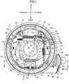
- a drum brake device 11 is provided in, for example, the left-rear wheel of a four-wheel vehicle and this drum brake device 11 includes a fixed back plate 13 having, at the center thereof, a through-hole 12 that passes through a wheel shaft 10 of the left rear wheel, first and second brake shoes 15 and 16 disposed in the back plate 13 so as to enable sliding contact with the inner periphery of a brake drum 14 that rotates together with the left rear wheel, a wheel cylinder 17 fixed to an upper portion of the back plate 13 so as to generate a force for operating the first and second brake shoes 15 and 16 in an expanded manner, a braking clearance automatic adjustment means (so-called automatic adjuster) 18 that automatically adjusts the clearance between the first and second brake shoes 15 and 16 and the brake drum 14, and a return spring 19 provided between the first and second brake shoes 15 and 16.
- a braking clearance automatic adjustment means so-called automatic adjuster
- the first and second brake shoes 15 and 16 include webs 15a and 16a formed in bows along the inner periphery of the brake drum 14, rims 15b and 16b provided in a linked manner orthogonally to the outer peripheries of the webs 15a and 16a, and linings 15c and 16c pasted to the outer peripheries of the rims 15b and 16b.
- the outer end portions of a pair of pistons 20 of the wheel cylinder 17 are disposed so as to face the webs 15a and 16a in the upper end portions of the first and second brake shoes 15 and 16.
- an anchor block 21 that functions as the fulcrum when the first and second brake shoes 15 and 16 are expanded or contracted is provided in a fixed manner in the lower portion of the back plate 13 so as to support one end portions (lower end portions in this embodiment) of the first and second brake shoes 15 and 16, and the wheel cylinder 17 is operated by the output hydraulic pressure of the master cylinder (not illustrated) operated by the brake pedal and generates a force for driving the first and second brake shoes 15 and 16 in an expanded manner using the anchor block 21 as the fulcrum.
- a coil spring 22 for biasing the lower end portions of the webs 15a and 16a of the first and second brake shoes 15 and 16 toward the anchor block 21 is provided between the lower end portions of the webs 15a and 16a and the return spring 19 for biasing the first and second brake shoes 15 and 16 in a contraction direction is provided between the upper end portions of the webs 15a and 16a of the first and second brake shoes 15 and 16.
- the braking clearance automatic adjustment means 18 includes a contraction position restricting strut 24 that is provided between the webs 15a and 16a of the first and second brake shoes 15 and 16 and stretchable by rotation of an adjustment gear 23, an adjustment lever 25 that has a feeding claw 25a to be engaged with the adjustment gear 23 and is pivotably supported by the web 16a of the second brake shoe 16, which is one of the first and second brake shoes 15 and 16, and an adjustment spring 26 that pivotally biases the adjustment lever 25 so as to rotate the adjustment gear 23 in the direction in which the contraction position restricting strut 24 is stretched.
- the contraction position restricting strut 24 restricts the contraction positions of the first and second brake shoes 15 and 16 and includes a first rod 27 that has a first engagement portion 27a to be engaged with an upper portion of the web 15a of the first brake shoe 15 of the first and second brake shoes 15 and 16, a second rod 28 that has a second engagement portion 28a to be engaged with an upper portion of the web 16a of the second brake shoe 16 and is disposed concentrically with the first rod 27, and an adjustment bolt 29 with one end portion inserted into the first rod 27 relatively movably in the axial direction and the other end portion to be screwed concentrically with the second rod 28, in which the adjustment gear 23 is disposed between the first and second rods 27 and 28 and formed in the outer periphery of the adjustment bolt 29.
- a first retaining recess 30 with which the first engagement portion 27a is engaged is provided in the upper portion of the web 15a of the first brake shoe 15 and a second retaining recess 31 with which the second engagement portion 28a is engaged is provided in the upper portion of the web 16a of the second brake shoe 16.
- the adjustment lever 25 having the feeding claw 25a to be engaged with the adjustment gear 23 is pivotably supported by the web 16a of the second brake shoe 16 via a support shaft 32 and the adjustment spring 26 is provided between the web 16a of the second brake shoe 16 and the adjustment lever 25. Furthermore, the spring force of the adjustment spring 26 is set smaller than the spring force of the return spring 19.
- the adjustment lever 25 is pivoted about the axial line of the support shaft 32 by the spring force of the adjustment spring 26 and the adjustment gear 23 is thereby rotated, and the effective length of the contraction position restricting strut 24 is corrected to a larger value.
- the drum brake device 11 is provided with a parking brake lever 34 having one end pivotably supported by the web 15a of the first brake shoe 15 of the first and second brake shoes 15 and 16 and engaged with one end portion of the contraction position restricting strut 24.
- the parking brake lever 34 extends upward and downward so as to partially overlap with the web 15a of the first brake shoe 15 in front view and the upper end portion of this parking brake lever 34 is connected to the upper portion of the web 15a of the first brake shoe 15 via a pin 35, and the first engagement portion 27a of the contraction position restricting strut 24 is engaged with the upper end portion of this parking brake lever 34.
- the parking brake lever 34 When the parking brake of the vehicle is operated, the parking brake lever 34 is driven pivotally counterclockwise about the pin 35 as the fulcrum and this pivot of the parking brake lever 34 causes a force for pressing the lining 16c of the brake shoe 16 against the inner periphery of the brake drum 14 to act on the second brake shoe 16 via the contraction position restricting strut 24.
- the parking brake lever 34 is continuously driven pivotally counterclockwise in Fig. 1
- the parking brake lever 34 is pivoted about the engagement point with respect to the first engagement portion 27a of the contraction position restricting strut 24 as the fulcrum, the first brake shoe 15 is operated in an expanded manner via the pin 35 and the lining 15c of the first brake shoe 15 is pressed against the inner periphery of the brake drum 14. That is, the parking brake lever 34 is operated at an operation position at which the linings 15c and 16c of the first and second brake shoes 15 and 16 are pressed against the inner periphery of the brake drum 14 and the parking brake state is obtained in this
- the parking brake lever 34 When application of a rotational driving force to the parking brake lever 34 is stopped, the parking brake lever 34 is returned to a non-operation position together with the first and second brake shoes 15 and 16 operated in a direction away from the inner periphery of the brake drum 14 by the spring force of the return spring 19 and the parking brake lever 34 is biased toward the non-operation position.
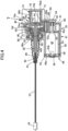
- the parking brake lever 34 is pivotally driven by the power generated by an electric actuator 36, the brake cable 37 pulled or loosened by the electric actuator 36 enables the parking brake state to be obtained by pivotally driving the parking brake lever 34 so as to press the contraction position restricting strut 24 against the web 15a of the second brake shoe 15 by pulling the brake cable 37 and enables the parking brake state to be released by loosening the brake cable 37, and the brake cable 37 is connected to a lower portion of the parking brake lever 34.
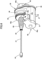
- the electric actuator 36 includes a screw shaft 38 that is connected to the brake cable 37, an actuator case 39 that supports the screw shaft 38 movably in an axial direction thereof, an electric motor 40 that is supported by the actuator case 39 rotatably forward and backward, and a motion conversion mechanism 41 that enables conversion from a rotational motion generated by the electric motor 40 to a linear motion of the screw shaft 38 and is accommodated in the actuator case 39 while being interposed between the electric motor 40 and the screw shaft 38, in which switching between the parking brake state reached by pulling the brake cable 37 and the parking brake release state reached by loosening the brake cable 37 is performed by a change in the rotational direction of the electric motor 40.
- a bottomed joint hole 42 is concentrically provided in the end portion of the screw shaft 38 close to the brake cable 37 and the end portion of the brake cable 37 close to the electric actuator 36 is inserted into the joint hole 42. Furthermore, an annular groove 43 is formed in the outer periphery of the screw shaft 38 close to the opening end of the joint hole 42 and the screw shaft 38 is connected to the brake cable 37 by swaging the annular groove 43 so that a part of the screw shaft 38 digs into the brake cable 37 in the state in which the brake cable 37 is inserted into the joint hole 42.
- the brake cable 37 is drawn into the back plate 13 from the electric actuator 36 mounted to the back plate 13 and an engagement piece 44 fixed to the other end portion of this brake cable 37 is engaged with the lower end portion of the parking brake lever 34.
- the electric actuator 36 switches between the state in which the screw shaft 38 is moved so as to pull the brake cable 37 to drive the parking brake lever 34 toward the operation position as illustrated in Fig. 5 and the state in which the screw shaft 38 is moved so as to loosen the brake cable 37 to return the parking brake lever 34 from the operation position toward the non-operation position as illustrated in Figs. 2 and 4 by a change in the rotational direction of the electric motor 40.
- a cable guide 51 that sandwiches the anchor block 21 between the cable guide 51 and the back plate 13 is mounted in the lower portion of the back plate 13 together with the anchor block 21 via a pair of rivets 52.
- this cable guide 51 is provided integrally with a guide portion 51a for guiding the brake cable 37 so as to have a substantially U-shaped cross section.
- the actuator case 39 includes a case main body 47 integrally having first and second accommodating cylindrical portions 45 and 46, a first cover member 48 coupled to the opening end of the first accommodating cylindrical portion 45, and a second cover member 49 coupled to the case main body 47 from the opposite side of the first cover member 48.
- the first accommodating cylindrical portion 45 is formed in a bottomed cylinder so as to have a support wall portion 45a on one end side thereof and a fitting hole 50 is concentrically formed at the center of the support wall portion 45a.
- the second accommodating cylindrical portion 46 is disposed to the side of the first accommodating cylindrical portion 45 and formed in a bottomed cylinder in which one end portion is open and the other end portion is closed by an end wall portion 46a disposed in an intermediate part in the longitudinal direction of the first accommodating cylindrical portion 45, and a cylindrical support cylindrical portion 46b passing through the screw shaft 38 is provided integrally in a projecting manner at the center of the end wall portion 46a.
- a cylindrical first bearing portion 53a that rotatably supports a motor shaft 54 is provided in a projecting manner in one end portion in the axial direction of a motor case 53 of the electric motor 40, the one end portion of the motor shaft 54 passes through the first bearing portion 53a and projects from one end portion of the motor case 53, and a bottomed-cylindrical second bearing portion 53b that rotatably supports the other end portion of the motor shaft 54 is provided in a projecting manner in the other end portion in the axial direction of the motor case 53.
- This electric motor 40 is accommodated in the first accommodating cylindrical portion 45 so that the one end portion of the motor case 53 abuts against the support wall portion 45a while the first bearing portion 53a is fitted to the fitting hole 50 of the case main body 47, and the electric motor 40 is accommodated in the first accommodating cylindrical portion 45 while a part (the other end portion of the motor case 53 in which the second bearing portion 53b is provided in the embodiment) of the electric motor 40 faces the outside.
- the first cover member 48 integrally has a lid portion 48a that covers the part of the electric motor 40 accommodated in the first accommodating cylindrical portion 45 that faces the outside from the first accommodating cylindrical portion 45 and is coupled to the opening end of the first accommodating cylindrical portion 45 and a connector portion 48b that overhands toward the side from the lid portion 48a so that a terminal 55 (see Fig. 3 ) continuous to the electric motor 40 is provided and is disposed to the side of the first accommodating cylindrical portion 45, and a wave washer 56 is interposed between the second bearing portion 53b and the lid portion 48a of the electric motor 40.
- the lid portion 48a is formed in a dish shape opened toward the first accommodating cylindrical portion 45 and an annular recess 58 concentric with the first accommodating cylindrical portion 45 having a circular cross section is formed at the open end of this lid portion 48a.
- an annular fitting projection portion 59 to be fitted to the annular recess 58 is provided in a projecting manner in the opening end portion of the first accommodating cylindrical portion 45.
- the lid portion 48a and the first accommodating cylindrical portion 45 are bonded to each other in the state in which the fitting projection portion 59 is fitted to the annular recess 58.
- the second cover member 49 is coupled to the case main body 47 via bonding or welding so as to form a gear chamber 60 between the second cover member 49 and the case main body 47.
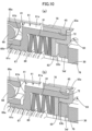
- the motion conversion mechanism 41 has a nut 61 to be screwed onto the screw shaft 38 as one component and is accommodated in the gear chamber 60.
- the motion conversion mechanism 41 includes a driving gear 62 provided in the motor shaft 54 of the electric motor 40, an intermediate large-diameter gear 63 to be meshed with the driving gear 62, an intermediate small-diameter gear 64 that rotates together with the intermediate large-diameter gear 63, a driven gear 65 that is meshed with this intermediate small-diameter gear 64, and the nut 61 to be connected to this driven gear 65 that enables the relative movement in the axial direction of the driven gear 65 and disables the relative rotation about the axial line, and the nut 61 is screwed onto the screw shaft 38.
- the intermediate large-diameter gear 63 and the intermediate small-diameter gear 64 are formed integrally with each other and are rotatably supported by a support shaft 66 arranged in parallel with the motor shaft 54 and the screw shaft 38.
- the nut 61 is formed to include a large-diameter cylindrical portion 61a rotatably accommodated in the second accommodating cylindrical portion 46, an inward collar portion 61b that overhangs radially inward from the end portion of the large-diameter cylindrical portion 61a on the opposite side of the second cover member 49, and a small-diameter cylindrical portion 61c that is continuous to the inner peripheral edge of this inward collar portion 61b, extends toward the opposite side of the second cover member 49, and passes through the screw shaft 38.
- Female threads 67 to be screwed onto the screw shaft 38 are engraved in the inner periphery of the small-diameter cylindrical portion 61c.
- a ball bearing 68 is interposed between the small-diameter cylindrical portion 61c and the end portion of the second accommodating cylindrical portion 46 close to the end wall portion 46a.
- An outer race 68a of this ball bearing 68 is press-fitted to the second accommodating cylindrical portion 46 and the small-diameter cylindrical portion 61c of the nut 61 is inserted into an inner race 68b of the ball bearing 68 movably in the axial direction.
- annular projection portion 70 projecting radially outward is provided integrally in a projecting manner in the intermediate portion in the longitudinal direction of the outer periphery of the large-diameter cylindrical portion 61a, and slits 71 extending in the axial direction are formed so as to cut the annular projection portion 70 at a plurality of positions (for example, four positions) spaced in the circumferential direction of this annular projection portion 70.
- guide projection portions 72 extending long in the axial direction are provided integrally in a projecting manner so as to project radially inward at a plurality of positions corresponding to the slits 71 in the inner periphery of the driven gear 65 and the guide projection portions 72 are slidably fitted to the slits 71. That is, the driven gear 65 is fitted onto the outer periphery of the large-diameter cylindrical portion 61a of the nut 61 while enabling relative movement in the axial direction and disabling relative rotation about the axial line.
- the second cover member 49 of the actuator case 39 is formed by integrally providing, in a linked manner, a cover plate portion 49a coupled to the case main body 47 so as to cover the gear chamber 60 and a bottomed cylindrical portion 49b projecting from the cover plate portion 49a so as to surround the screw shaft 38 and a guide cylindrical portion 74a integrally owned by an insertion member 74 accommodated and fixed in the actuator case 39 is fitted to the cylindrical portion 49b.
- the guide cylindrical portion 74a is formed to include a cylindrical part 74aa and a plurality of overhang parts 74ab overhanging radially from the cylindrical part 74aa and the pair of overhang parts 74ab is disposed in one diameter line of the cylindrical part 74aa in the embodiment.
- the overhang part 74ab forms rotation restricting grooves 75 extending along the axial line of the cylindrical part 74aa.
- the cylindrical portion 49b of this second cover member 49 is formed to have an inner surface shape corresponding to the outer surface shape of the guide cylindrical portion 74a.
- the insertion member 74 is integrally provided with an extended cylindrical portion 74b that is continuous to the guide cylindrical portion 74a and enters the gear chamber 60, a plurality of (for example, two) mount arm portions 74c that overhang outward to the side from the end portion of the guide cylindrical portion 74a close to the gear chamber 60 along the inner surface of the cover plate portion 49a of the second cover member 49, and one support arm portion 74d that overhands outward to the side from the end portion of the guide cylindrical portion 74a close to the gear chamber 60 along the inner surface of the cover plate portion 49a.
- a positioning projection portion 74e projecting toward the second accommodating cylindrical portion 46 is provided integrally in a projecting manner in a front end portion of the mount arm portion 74c and the insertion member 74 is accommodated and fixed in the actuator case 39 by sandwiching the front end portion of the mount arm portion 74c and the positioning projection portion 74e between the second accommodating cylindrical portion 46 and the cover plate portion 49a of the second cover member 49.
- both end portions of the support shaft 66 for rotatably supporting the intermediate large-diameter gear 63 and the intermediate small-diameter gear 64 are supported between the front end portion of the support arm portion 74d and the support wall portion 45a of the first accommodating cylindrical portion 45.
- a rotation restricting means 73 for restricting the rotation of the screw shaft 38 is provided between the guide cylindrical portion 74a of the insertion member 74 and the screw shaft 38 and this rotation restricting means 73 includes a plurality of (two in the embodiment) rotation restricting projection portions 76b that are provided in the end portion of the screw shaft 38 on the opposite side of the brake cable 37 and radially project from the screw shaft 38 and the plurality of (two in the embodiment) rotation restricting grooves 75 that are formed in the guide cylindrical portion 74a so as to be entered by the rotation restricting projection portions 76b.
- a cap 76 is put on the end portion of the screw shaft 38 on the opposite side of the brake cable 37.
- This cap 76 is formed by integrally providing a bottomed cylindrical portion 76a to which the end portion of the screw shaft 38 is fitted and the plurality of the rotation restricting projection portions 76b radially projecting from the bottomed cylindrical portion 76a so as to be inserted into the rotation restricting grooves 75 of the guide cylindrical portion 74a of the insertion member 74 and, in the embodiment, the pair of rotation restricting projection portions 76b projects radially outward from the bottomed cylindrical portion 76a along the one diameter line of the bottomed cylindrical portion 76a.
- the cap 76 is fixed to the screw shaft 38 as the linked member together with the screw shaft 38 via a pin 77 that passes through the screw shaft 38 and the bottomed cylindrical portion 76a along the one diameter line.
- This provides the pair of rotation restricting projection portions 76b in the end portion of the screw shaft 38 on the opposite side of the brake cable 37, causes the rotation restricting projection portions 76b to enter the rotation restricting grooves 75 of the insertion member 74 accommodated and fixed in the actuator case 39, and makes the screw shaft 38 movable in a direction along the axial line while being prevented from rotating about the axial line.
- the movement end of the screw shaft 38 in movement in the direction loosening the brake cable 37 is restricted by causing the cap 76 to abut against a movement restricting portion 74f accommodated and fixed in the actuator case 39 and, in the embodiment, the movement restricting portion 74f is integrally provided at the front end of the extended cylindrical portion 74b of the insertion member 74. That is, the movement restricting portion 74f is integrally provided in the front end portion of the extended cylindrical portion 74b so as to overhang radially inward from the front end portion of the extended cylindrical portion 74b.
- the plurality of disc springs 80 and a disc-shaped retainer 82 that sandwiches these disc springs 80 between the disc-shaped retainer 82 and the inward collar portion 61b of the nut 61 are accommodated in the recess 81.
- the nut 61 is provided with a holding member 83 for preventing the disc springs 80 and the retainer 82 from being removed from the recess 81 on the opening end side of the recess 80, this holding member 83 is formed to integrally have a ring plate portion 83a that abuts against the end portion of the large-diameter cylindrical portion 61a of the nut 61 close to the insertion member 74 and a short cylindrical portion 83b that is continuous to the inner periphery of this ring plate portion 83a and press-fitted to the large-diameter cylindrical portion 61a of the nut 61, the inner diameter of the short cylindrical portion 83b is set larger than the outer diameter of the movement restricting portion 74f, and the side wall of
- the retainer 82 abuts against the movement restricting portion 74f of the insertion member 74 in response to the movement in the axial direction of the nut 61, the disc springs 80 are compressed between the nut 61 and the movement restricting portion 74f, thereby enabling an increase in the load on the electric motor 40.
- a mount cylindrical portion 85 extending backward and inward in the vehicle width direction is provided integrally in a projecting manner on the back plate 13 of the drum brake device 11.
- This mount cylindrical portion 85 is provided with a large-diameter cylindrical portion 85a with one end that is open backward and inward in the vehicle width direction and a small-diameter cylindrical portion 85c that is concentrically continuous to the large-diameter cylindrical portion 85a with a step portion 85b provided between the small-diameter cylindrical portion 85c and the other end of the large-diameter cylindrical portion 85a.
- the actuator case 39 is mounted to the mount cylindrical portion 85 by inserting the second accommodating cylindrical portion 46 of the first cover member 48 in the actuator case 39 of the electric actuator 36 into the large-diameter cylindrical portion 85a and engaging a C-shaped locking ring 88 mounted to the outer periphery of the second accommodating cylindrical portion 46 with a locking groove 87 formed in the inner periphery of the large-diameter cylindrical portion 85a.
- the actuator case 39 When the actuator case 39 is mounted to the mount cylindrical portion 85 of the back plate 13 as described above, the actuator case 39 is mounted to the rear side in the front-rear direction of the vehicle of the back plate 13 and the connector portion 48b is oriented to the rear side in the front-rear direction of the vehicle.
- a bellows boot 89 for covering a projection portion of the screw shaft 38 from the second accommodating cylindrical portion 46 is provided between the outer periphery of the support cylindrical portion 46b of the second accommodating cylindrical portion 46 and the outer periphery of one end portion of the screw shaft 38.
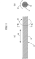
- the brake cable 37 is a bunch of a plurality of twisted wires 92 and generates a twisting force in the direction indicated by arrow 91 in Figs. 11(a) and 11(b) when pulled in the direction indicated by arrow 90 in Fig. 11(a) to obtain the parking brake state.
- a setting is made so that the direction in which the twisting force in this case acts on the screw shaft 38 is the same as the rotational direction of the nut 61 when the electric motor 40 operates in the direction loosening the brake cable 37 for switching from the parking brake state to the parking brake release state.
- the nut 61 of the motion conversion mechanism 41 capable of converting a rotational motion generated by the electric motor 40 to a linear motion of the screw shaft 38 connected to the brake cable 37 is screwed onto the screw shaft 38 movably in the axial direction within a restricted range in a direction along the axial line of the screw shaft 38, the movement restricting portion 74f that restricts the movement end in the axial direction of the screw shaft 38 in movement to the side loosening the brake cable 37 to reach the parking brake release state by causing the cap 76 as the linked member that moves in the axial direction together with the screw shaft 38 to abut thereagainst is provided in a fixed position in the actuator case 39, and the disc springs 80, which are resilient members, are interposed between the nut 61 and the insertion member 74 accommodated and fixed in the actuator case 39 so as to be compressed in response to movement of the nut 61 in the axial direction after the movement end is restricted by the movement restricting portion 74f when the screw shaft
- the electric motor 40 can be controlled appropriately and the members constituting the motion conversion mechanism 41 can be prevented from shifting to a lock state. Furthermore, since the nut 61 is relatively movable in the axial direction with respect to the screw shaft 38, generation of an operating sound in parking brake release operation can be prevented. In addition, since the disc springs 80 are provided between the insertion member 74 accommodated and fixed in the actuator case 39 and the nut 61, the strength of the actuator case 39 does not need to be increased more than necessity.
- the internal structure of the actuator case 39 can be simplified while suppressing an increase in the number of components by providing the disc springs 80 between the nut 61 and the movement restricting portion 74f provided integrally with the insertion member 74.
- the resilient members are the disc springs 80
- the space that needs to be reserved in the actuator case 39 to dispose the disc springs 80 can be reduced and the actuator case 39 can be small-sized.
- the brake cable 37 is formed by twisting the plurality of wires 92 so as to generate a twisting force when pulled and the direction in which the twisting force acts on the screw shaft 38 is the same as the rotational direction of the nut 61 when the brake cable 37 is loosened, even if the nut 61 is rotated so as to obtain the parking brake state, the screw shaft 38 is rotated and reaches a rotary position A indicated by the dotted line in Fig.
- the rotation restricting projection portions 76b are returned to the vicinity of a rotary position B indicated by the dotted line in Fig. 9 by the twisting force from the brake cable 37 when the parking brake state is maintained. Even when the rotation restricting projection portions 76b of the cap 76 reach the rotary position B by the backward rotation of the nut 61 during switching from the parking brake state to the parking brake release state and make contact with the side surface of the rotation restricting grooves 75 of the insertion member 74, it is possible to prevent the cap 76 and the insertion member 74 from strongly colliding with each other, suppress the generation of a slapping sound, and reduce the operating sound.
- the rotation restricting means 73 includes the plurality of rotation restricting projection portions 76b that are provided in the end portion of the screw shaft 38 opposite to the brake cable 37 and radially project from the screw shaft 38 and the plurality of the rotation restricting grooves 75 formed in the insertion member 74 so as to be entered by the rotation restricting projection portions 76b, the operating sound can be reduced more effectively by restricting the rotation of the screw shaft 38 at a plurality of positions in the circumferential direction of the screw shaft 38.
- the portion corresponding to the cap 76 may be formed integrally with the screw shaft 38 and, in this case, the movement end of the screw shaft 38 on the side loosening the brake cable is restricted by abutment against the movement restricting portion 74f.
Landscapes
- Engineering & Computer Science (AREA)
- General Engineering & Computer Science (AREA)
- Mechanical Engineering (AREA)
- Transportation (AREA)
- Braking Arrangements (AREA)
- Braking Systems And Boosters (AREA)
Description
- The present invention relates to an electric parking brake device including a screw shaft that is connected to a brake cable so as to be prevented from rotating; an actuator case that supports the screw shaft movably in an axial direction thereof; an electric motor that is supported by the actuator case rotatably forward and backward; a motion conversion mechanism that has a nut to be screwed onto the screw shaft rotatably in response to an operation of the electric motor, enables conversion from a rotational motion generated by the electric motor to a linear motion of the screw shaft, and is accommodated in the actuator case; and a resilient member that is compressed when the screw shaft is moved to a side loosening the brake cable, in which switching between a parking brake state reached by pulling the brake cable and a parking brake release state reached by loosening the brake cable is performed by a change in a rotational direction of the electric motor.
- An electric parking brake device that switches between a state in which a parking brake force is obtained by pulling a brake cable and a state in which a parking brake force is released by loosening the brake cable by a change in the rotational direction of an electric motor is known in PTL 1.
-
EP 3184381 A1 discloses an electric parking brake including a screw shaft axially movable by the rotation of a nut, a movement restricting portion located outside the actuator case to restrict the axial movement of the screw shaft, and a resilient member compressed by the nut when the screw shaft abuts the movement restricting portion. -
WO 2017/097696 A1 ,DE 102012201579 A1 andJP 2017171299 A -
KR 102322481 B1 - PTL 1:
Japanese Patent No. 6184873 - By the way, when a parking brake is released in an electric parking brake device, the load on an electric motor becomes small, no-load current flows, and over returning occurs in a plurality of members that constitute a motion conversion mechanism between the electric motor and a screw shaft, possibly falling into a locked state. Accordingly, the electric parking brake device disclosed in PTL 1 above prevents over returning by monitoring the current passing through the electric motor while applying a load by a resilient member to the screw shaft and a nut to preferably interrupt the power supplied to the electric motor when a parking brake is released. On the other hand, since the position in the axial direction of the nut is fixed, an operating sound is easily generated when the parking brake is released. In addition, since the resilient member is interposed in a part of the screw shaft, that is, in a portion between the nut and the actuator case accommodating the motion conversion mechanism and the resilient member, the strength of the actuator case needs to be improved.
- The invention addresses the above situation with an object of providing an electric parking brake device capable of applying a load to an electric motor when a parking brake state is released without generating an operating sound when a parking brake state is released and making the strength of the actuator case unnecessarily large.
- To achieve the above object, according to a first aspect of the invention, there is provided an electric parking brake device including a screw shaft; a brake cable; an actuator case that supports the screw shaft movably in an axial direction thereof; an electric motor that is supported by the actuator case rotatably forward and backward; a motion conversion mechanism that has a nut to be screwed onto the screw shaft rotatably in response to an operation of the electric motor, enables conversion from a rotational motion generated by the electric motor to a linear motion of the screw shaft, and is accommodated in the actuator case; and a resilient member that is compressed when the screw shaft is moved to a side loosening the brake cable, in which switching between a parking brake state reached by pulling the brake cable and a parking brake release state reached by loosening the brake cable is performed by a change in a rotational direction of the electric motor, in which the nut is screwed onto the screw shaft movably in the axial direction within a restricted range, and a movement restricting portion, the movement restricting portion restricts an end of axial movement, toward the side loosening the brake cable, of the screw shaft or of a linked member that moves axially together with the screw shaft by causing the screw shaft or the linked member to abut against the movement restricting portion, wherein the screw shaft is connected to the brake cable so as to be prevented from rotating; and the movement restricting portion is provided in a fixed position in the actuator case; characterized in that the resilient member is interposed between the nut and an insertion member accommodated and fixed in the actuator case so as to be compressed in response to axial movement of the nut after the movement end of the screw shaft or linked member is restricted by the movement restricting portion when the screw shaft moves axially to the side loosening the brake cable; wherein the movement restricting portion is provided integrally with the insertion member so that the resilient member is interposed between the movement restricting portion and the nut.
- In a second aspect of the invention, the resilient member is a disc spring in addition to the structure of the first or second aspect.
- According to the first aspect of the invention, if the nut is rotated so as to move the screw shaft to the side loosening the brake cable by the electric motor when the brake cable is loosened to release the parking brake state, since the nut is moved in the axial direction within a restricted range in response to the operation of the electric motor in the state after movement in the axial direction of the screw shaft is restricted by the movement restricting portion, the resilient member is compressed in response to the movement in the axial direction of the nut, thereby increasing the load on the electric motor. Accordingly, the electric motor can be controlled appropriately and the members constituting the motion conversion mechanism can be prevented from falling into a lock state. In addition, since the nut is relatively movable with respect to the screw shaft, an operating sound can be prevented from being generated when the parking brake is released and the strength of the actuator case does not need to be improved unnecessarily because the resilient member is provided between the nut and the insertion member accommodated and fixed in the actuator case.
- In addition, according to the first aspect of the invention, since the resilient member is interposed between the nut and the movement restricting portion provided integrally with insertion member, the internal structure of the actuator case can be simplified while suppressing an increase in the number of components.
- In addition, according to the second aspect of the invention, since the resilient member is a disc spring, the space that needs to be reserved in the actuator case to dispose the resilient member can be reduced and the actuator case can be small-sized.
-
- [
Fig. 1] Fig. 1 is a front view illustrating a drum brake device (first embodiment). - [
Fig. 2] Fig. 2 is a sectional view taken along line 2-2 inFig. 1 (first embodiment). - [
Fig. 3] Fig. 3 is a perspective view seen alongarrow 3 inFig. 1 (first embodiment). - [
Fig. 4] Fig.4 is a sectional view, taken along line 4-4 inFig. 3 , that illustrates the state in which a brake cable is being loosened (first embodiment). - [
Fig. 5] Fig. 5 is a sectional view, corresponding toFig. 4 , that illustrates the state in which the brake cable has been pulled (first embodiment). - [
Fig. 6] Fig. 6 is a perspective view illustrating an electric actuator (first embodiment). - [
Fig. 7] Fig. 7 is an enlarged view illustrating the portion indicated byarrow 7 inFig. 4 (first embodiment). - [
Fig. 8] Fig. 8 is a sectional view taken along line 8-8 inFig. 7 (first embodiment). - [
Fig. 9] Fig. 9 is a sectional view taken along line 9-9 inFig. 5 (first embodiment). - [
Fig. 10] Figs. 10(a) and 10(b) are main part vertical perspective views illustrating the state in which movement of a screw shaft is restricted by a movement restricting portion when a nut is rotated the side loosening the brake cable and the state after that, respectively (first embodiment). - [
Fig. 11] Fig. 11 illustrates the generation of a twisting force in the brake cable,Fig. 11(a) is a side view illustrating the brake cable, andFig. 11(b) is a sectional view taken along line b-b inFig. 11(a) (first embodiment). -
- 37: brake cable
- 38: screw shaft
- 39: actuator case
- 40: electric motor
- 41: motion conversion mechanism
- 61: nut
- 74f: movement restricting portion
- 74: insertion member
- 76: cap as linked member
- 80: disc spring as resilient member
- An embodiment of the invention will be described with reference to attached
Figs. 1 to 11 . - In
Figs. 1 to 3 , adrum brake device 11 is provided in, for example, the left-rear wheel of a four-wheel vehicle and thisdrum brake device 11 includes a fixedback plate 13 having, at the center thereof, a through-hole 12 that passes through awheel shaft 10 of the left rear wheel, first andsecond brake shoes back plate 13 so as to enable sliding contact with the inner periphery of abrake drum 14 that rotates together with the left rear wheel, awheel cylinder 17 fixed to an upper portion of theback plate 13 so as to generate a force for operating the first andsecond brake shoes second brake shoes brake drum 14, and areturn spring 19 provided between the first andsecond brake shoes - The first and
second brake shoes webs brake drum 14,rims webs linings rims - The outer end portions of a pair of
pistons 20 of thewheel cylinder 17 are disposed so as to face thewebs second brake shoes anchor block 21 that functions as the fulcrum when the first andsecond brake shoes back plate 13 so as to support one end portions (lower end portions in this embodiment) of the first andsecond brake shoes wheel cylinder 17 is operated by the output hydraulic pressure of the master cylinder (not illustrated) operated by the brake pedal and generates a force for driving the first andsecond brake shoes anchor block 21 as the fulcrum. - A
coil spring 22 for biasing the lower end portions of thewebs second brake shoes anchor block 21 is provided between the lower end portions of thewebs return spring 19 for biasing the first andsecond brake shoes webs second brake shoes - The braking clearance automatic adjustment means 18 includes a contraction
position restricting strut 24 that is provided between thewebs second brake shoes adjustment gear 23, anadjustment lever 25 that has afeeding claw 25a to be engaged with theadjustment gear 23 and is pivotably supported by theweb 16a of thesecond brake shoe 16, which is one of the first andsecond brake shoes adjustment spring 26 that pivotally biases theadjustment lever 25 so as to rotate theadjustment gear 23 in the direction in which the contractionposition restricting strut 24 is stretched. - The contraction
position restricting strut 24 restricts the contraction positions of the first andsecond brake shoes first rod 27 that has afirst engagement portion 27a to be engaged with an upper portion of theweb 15a of thefirst brake shoe 15 of the first andsecond brake shoes second rod 28 that has asecond engagement portion 28a to be engaged with an upper portion of theweb 16a of thesecond brake shoe 16 and is disposed concentrically with thefirst rod 27, and anadjustment bolt 29 with one end portion inserted into thefirst rod 27 relatively movably in the axial direction and the other end portion to be screwed concentrically with thesecond rod 28, in which theadjustment gear 23 is disposed between the first andsecond rods adjustment bolt 29. - A first retaining recess 30 with which the
first engagement portion 27a is engaged is provided in the upper portion of theweb 15a of thefirst brake shoe 15 and asecond retaining recess 31 with which thesecond engagement portion 28a is engaged is provided in the upper portion of theweb 16a of thesecond brake shoe 16. - The
adjustment lever 25 having thefeeding claw 25a to be engaged with theadjustment gear 23 is pivotably supported by theweb 16a of thesecond brake shoe 16 via asupport shaft 32 and theadjustment spring 26 is provided between theweb 16a of thesecond brake shoe 16 and theadjustment lever 25. Furthermore, the spring force of theadjustment spring 26 is set smaller than the spring force of thereturn spring 19. - In the braking clearance automatic adjustment means 18 described above, if the first and
second brake shoes linings second brake shoes wheel cylinder 17, theadjustment lever 25 is pivoted about the axial line of thesupport shaft 32 by the spring force of theadjustment spring 26 and theadjustment gear 23 is thereby rotated, and the effective length of the contractionposition restricting strut 24 is corrected to a larger value. - By the way, the
drum brake device 11 is provided with aparking brake lever 34 having one end pivotably supported by theweb 15a of thefirst brake shoe 15 of the first andsecond brake shoes position restricting strut 24. - The
parking brake lever 34 extends upward and downward so as to partially overlap with theweb 15a of thefirst brake shoe 15 in front view and the upper end portion of thisparking brake lever 34 is connected to the upper portion of theweb 15a of thefirst brake shoe 15 via apin 35, and thefirst engagement portion 27a of the contractionposition restricting strut 24 is engaged with the upper end portion of thisparking brake lever 34. - When the parking brake of the vehicle is operated, the
parking brake lever 34 is driven pivotally counterclockwise about thepin 35 as the fulcrum and this pivot of theparking brake lever 34 causes a force for pressing thelining 16c of thebrake shoe 16 against the inner periphery of thebrake drum 14 to act on thesecond brake shoe 16 via the contractionposition restricting strut 24. In addition, when theparking brake lever 34 is continuously driven pivotally counterclockwise inFig. 1 , theparking brake lever 34 is pivoted about the engagement point with respect to thefirst engagement portion 27a of the contractionposition restricting strut 24 as the fulcrum, thefirst brake shoe 15 is operated in an expanded manner via thepin 35 and thelining 15c of thefirst brake shoe 15 is pressed against the inner periphery of thebrake drum 14. That is, theparking brake lever 34 is operated at an operation position at which thelinings second brake shoes brake drum 14 and the parking brake state is obtained in this state. - When application of a rotational driving force to the
parking brake lever 34 is stopped, theparking brake lever 34 is returned to a non-operation position together with the first andsecond brake shoes brake drum 14 by the spring force of thereturn spring 19 and theparking brake lever 34 is biased toward the non-operation position. - The
parking brake lever 34 is pivotally driven by the power generated by anelectric actuator 36, thebrake cable 37 pulled or loosened by theelectric actuator 36 enables the parking brake state to be obtained by pivotally driving theparking brake lever 34 so as to press the contractionposition restricting strut 24 against theweb 15a of thesecond brake shoe 15 by pulling thebrake cable 37 and enables the parking brake state to be released by loosening thebrake cable 37, and thebrake cable 37 is connected to a lower portion of theparking brake lever 34. - Referring to
Figs. 4 and5 together, theelectric actuator 36 includes ascrew shaft 38 that is connected to thebrake cable 37, anactuator case 39 that supports thescrew shaft 38 movably in an axial direction thereof, anelectric motor 40 that is supported by theactuator case 39 rotatably forward and backward, and amotion conversion mechanism 41 that enables conversion from a rotational motion generated by theelectric motor 40 to a linear motion of thescrew shaft 38 and is accommodated in theactuator case 39 while being interposed between theelectric motor 40 and thescrew shaft 38, in which switching between the parking brake state reached by pulling thebrake cable 37 and the parking brake release state reached by loosening thebrake cable 37 is performed by a change in the rotational direction of theelectric motor 40. - A bottomed
joint hole 42 is concentrically provided in the end portion of thescrew shaft 38 close to thebrake cable 37 and the end portion of thebrake cable 37 close to theelectric actuator 36 is inserted into thejoint hole 42. Furthermore, anannular groove 43 is formed in the outer periphery of thescrew shaft 38 close to the opening end of thejoint hole 42 and thescrew shaft 38 is connected to thebrake cable 37 by swaging theannular groove 43 so that a part of thescrew shaft 38 digs into thebrake cable 37 in the state in which thebrake cable 37 is inserted into thejoint hole 42. - The
brake cable 37 is drawn into theback plate 13 from theelectric actuator 36 mounted to theback plate 13 and anengagement piece 44 fixed to the other end portion of thisbrake cable 37 is engaged with the lower end portion of theparking brake lever 34. - The
electric actuator 36 switches between the state in which thescrew shaft 38 is moved so as to pull thebrake cable 37 to drive theparking brake lever 34 toward the operation position as illustrated inFig. 5 and the state in which thescrew shaft 38 is moved so as to loosen thebrake cable 37 to return theparking brake lever 34 from the operation position toward the non-operation position as illustrated inFigs. 2 and4 by a change in the rotational direction of theelectric motor 40. - In the lower portion of the
back plate 13, acable guide 51 that sandwiches theanchor block 21 between thecable guide 51 and theback plate 13 is mounted in the lower portion of theback plate 13 together with theanchor block 21 via a pair ofrivets 52. As clearly illustrated inFig. 2 , thiscable guide 51 is provided integrally with aguide portion 51a for guiding thebrake cable 37 so as to have a substantially U-shaped cross section. - Referring to
Fig. 6 together, theactuator case 39 includes a casemain body 47 integrally having first and second accommodatingcylindrical portions first cover member 48 coupled to the opening end of the first accommodatingcylindrical portion 45, and asecond cover member 49 coupled to the casemain body 47 from the opposite side of thefirst cover member 48. - The first accommodating
cylindrical portion 45 is formed in a bottomed cylinder so as to have asupport wall portion 45a on one end side thereof and afitting hole 50 is concentrically formed at the center of thesupport wall portion 45a. The second accommodatingcylindrical portion 46 is disposed to the side of the first accommodatingcylindrical portion 45 and formed in a bottomed cylinder in which one end portion is open and the other end portion is closed by anend wall portion 46a disposed in an intermediate part in the longitudinal direction of the first accommodatingcylindrical portion 45, and a cylindrical supportcylindrical portion 46b passing through thescrew shaft 38 is provided integrally in a projecting manner at the center of theend wall portion 46a. - A cylindrical
first bearing portion 53a that rotatably supports amotor shaft 54 is provided in a projecting manner in one end portion in the axial direction of amotor case 53 of theelectric motor 40, the one end portion of themotor shaft 54 passes through thefirst bearing portion 53a and projects from one end portion of themotor case 53, and a bottomed-cylindricalsecond bearing portion 53b that rotatably supports the other end portion of themotor shaft 54 is provided in a projecting manner in the other end portion in the axial direction of themotor case 53. - This
electric motor 40 is accommodated in the first accommodatingcylindrical portion 45 so that the one end portion of themotor case 53 abuts against thesupport wall portion 45a while thefirst bearing portion 53a is fitted to thefitting hole 50 of the casemain body 47, and theelectric motor 40 is accommodated in the first accommodatingcylindrical portion 45 while a part (the other end portion of themotor case 53 in which thesecond bearing portion 53b is provided in the embodiment) of theelectric motor 40 faces the outside. - The
first cover member 48 integrally has alid portion 48a that covers the part of theelectric motor 40 accommodated in the first accommodatingcylindrical portion 45 that faces the outside from the first accommodatingcylindrical portion 45 and is coupled to the opening end of the first accommodatingcylindrical portion 45 and aconnector portion 48b that overhands toward the side from thelid portion 48a so that a terminal 55 (seeFig. 3 ) continuous to theelectric motor 40 is provided and is disposed to the side of the first accommodatingcylindrical portion 45, and awave washer 56 is interposed between thesecond bearing portion 53b and thelid portion 48a of theelectric motor 40. - The
lid portion 48a is formed in a dish shape opened toward the first accommodatingcylindrical portion 45 and anannular recess 58 concentric with the first accommodatingcylindrical portion 45 having a circular cross section is formed at the open end of thislid portion 48a. In contrast, an annularfitting projection portion 59 to be fitted to theannular recess 58 is provided in a projecting manner in the opening end portion of the first accommodatingcylindrical portion 45. Thelid portion 48a and the first accommodatingcylindrical portion 45 are bonded to each other in the state in which thefitting projection portion 59 is fitted to theannular recess 58. This enables the relative position in the circumferential direction of theconnector portion 48b with respect to the first accommodatingcylindrical portion 45 to be selected at a plurality of positions about the axial line of the first accommodatingcylindrical portion 45, increases the freedom of the position of theconnector portion 48b with respect to theactuator case 39, and facilitates changes in the orientation of theconnector portion 48b. - The
second cover member 49 is coupled to the casemain body 47 via bonding or welding so as to form agear chamber 60 between thesecond cover member 49 and the casemain body 47. In addition, themotion conversion mechanism 41 has anut 61 to be screwed onto thescrew shaft 38 as one component and is accommodated in thegear chamber 60. - The
motion conversion mechanism 41 includes adriving gear 62 provided in themotor shaft 54 of theelectric motor 40, an intermediate large-diameter gear 63 to be meshed with thedriving gear 62, an intermediate small-diameter gear 64 that rotates together with the intermediate large-diameter gear 63, a drivengear 65 that is meshed with this intermediate small-diameter gear 64, and thenut 61 to be connected to this drivengear 65 that enables the relative movement in the axial direction of the drivengear 65 and disables the relative rotation about the axial line, and thenut 61 is screwed onto thescrew shaft 38. In addition, the intermediate large-diameter gear 63 and the intermediate small-diameter gear 64 are formed integrally with each other and are rotatably supported by asupport shaft 66 arranged in parallel with themotor shaft 54 and thescrew shaft 38. - Referring to
Fig. 7 together, thenut 61 is formed to include a large-diametercylindrical portion 61a rotatably accommodated in the second accommodatingcylindrical portion 46, aninward collar portion 61b that overhangs radially inward from the end portion of the large-diametercylindrical portion 61a on the opposite side of thesecond cover member 49, and a small-diametercylindrical portion 61c that is continuous to the inner peripheral edge of thisinward collar portion 61b, extends toward the opposite side of thesecond cover member 49, and passes through thescrew shaft 38. -
Female threads 67 to be screwed onto thescrew shaft 38 are engraved in the inner periphery of the small-diametercylindrical portion 61c. In addition, aball bearing 68 is interposed between the small-diametercylindrical portion 61c and the end portion of the second accommodatingcylindrical portion 46 close to theend wall portion 46a. Anouter race 68a of thisball bearing 68 is press-fitted to the second accommodatingcylindrical portion 46 and the small-diametercylindrical portion 61c of thenut 61 is inserted into aninner race 68b of theball bearing 68 movably in the axial direction. - Referring to
Fig. 8 together, anannular projection portion 70 projecting radially outward is provided integrally in a projecting manner in the intermediate portion in the longitudinal direction of the outer periphery of the large-diametercylindrical portion 61a, and slits 71 extending in the axial direction are formed so as to cut theannular projection portion 70 at a plurality of positions (for example, four positions) spaced in the circumferential direction of thisannular projection portion 70. On the other hand, guideprojection portions 72 extending long in the axial direction are provided integrally in a projecting manner so as to project radially inward at a plurality of positions corresponding to theslits 71 in the inner periphery of the drivengear 65 and theguide projection portions 72 are slidably fitted to theslits 71. That is, the drivengear 65 is fitted onto the outer periphery of the large-diametercylindrical portion 61a of thenut 61 while enabling relative movement in the axial direction and disabling relative rotation about the axial line. - Referring to
Fig. 9 together, thesecond cover member 49 of theactuator case 39 is formed by integrally providing, in a linked manner, acover plate portion 49a coupled to the casemain body 47 so as to cover thegear chamber 60 and a bottomedcylindrical portion 49b projecting from thecover plate portion 49a so as to surround thescrew shaft 38 and a guidecylindrical portion 74a integrally owned by aninsertion member 74 accommodated and fixed in theactuator case 39 is fitted to thecylindrical portion 49b. - The guide
cylindrical portion 74a is formed to include a cylindrical part 74aa and a plurality of overhang parts 74ab overhanging radially from the cylindrical part 74aa and the pair of overhang parts 74ab is disposed in one diameter line of the cylindrical part 74aa in the embodiment. In addition, the overhang part 74ab formsrotation restricting grooves 75 extending along the axial line of the cylindrical part 74aa. Thecylindrical portion 49b of thissecond cover member 49 is formed to have an inner surface shape corresponding to the outer surface shape of the guidecylindrical portion 74a. - The
insertion member 74 is integrally provided with an extendedcylindrical portion 74b that is continuous to the guidecylindrical portion 74a and enters thegear chamber 60, a plurality of (for example, two)mount arm portions 74c that overhang outward to the side from the end portion of the guidecylindrical portion 74a close to thegear chamber 60 along the inner surface of thecover plate portion 49a of thesecond cover member 49, and onesupport arm portion 74d that overhands outward to the side from the end portion of the guidecylindrical portion 74a close to thegear chamber 60 along the inner surface of thecover plate portion 49a. - In addition, a
positioning projection portion 74e projecting toward the second accommodatingcylindrical portion 46 is provided integrally in a projecting manner in a front end portion of themount arm portion 74c and theinsertion member 74 is accommodated and fixed in theactuator case 39 by sandwiching the front end portion of themount arm portion 74c and thepositioning projection portion 74e between the second accommodatingcylindrical portion 46 and thecover plate portion 49a of thesecond cover member 49. - In addition, both end portions of the
support shaft 66 for rotatably supporting the intermediate large-diameter gear 63 and the intermediate small-diameter gear 64 are supported between the front end portion of thesupport arm portion 74d and thesupport wall portion 45a of the first accommodatingcylindrical portion 45. - Focusing on
Fig. 9 , a rotation restricting means 73 for restricting the rotation of thescrew shaft 38 is provided between the guidecylindrical portion 74a of theinsertion member 74 and thescrew shaft 38 and this rotation restricting means 73 includes a plurality of (two in the embodiment) rotation restrictingprojection portions 76b that are provided in the end portion of thescrew shaft 38 on the opposite side of thebrake cable 37 and radially project from thescrew shaft 38 and the plurality of (two in the embodiment)rotation restricting grooves 75 that are formed in the guidecylindrical portion 74a so as to be entered by the rotation restrictingprojection portions 76b. - A
cap 76 is put on the end portion of thescrew shaft 38 on the opposite side of thebrake cable 37. Thiscap 76 is formed by integrally providing a bottomedcylindrical portion 76a to which the end portion of thescrew shaft 38 is fitted and the plurality of the rotation restrictingprojection portions 76b radially projecting from the bottomedcylindrical portion 76a so as to be inserted into therotation restricting grooves 75 of the guidecylindrical portion 74a of theinsertion member 74 and, in the embodiment, the pair of rotation restrictingprojection portions 76b projects radially outward from the bottomedcylindrical portion 76a along the one diameter line of the bottomedcylindrical portion 76a. In addition, thecap 76 is fixed to thescrew shaft 38 as the linked member together with thescrew shaft 38 via apin 77 that passes through thescrew shaft 38 and the bottomedcylindrical portion 76a along the one diameter line. This provides the pair of rotation restrictingprojection portions 76b in the end portion of thescrew shaft 38 on the opposite side of thebrake cable 37, causes the rotation restrictingprojection portions 76b to enter therotation restricting grooves 75 of theinsertion member 74 accommodated and fixed in theactuator case 39, and makes thescrew shaft 38 movable in a direction along the axial line while being prevented from rotating about the axial line. - By the way, when the
brake cable 37 is pulled to drive theparking brake lever 34 toward the operation position, thescrew shaft 38 moves in a direction in which thecap 76 separates from thenut 61 as illustrated inFig. 5 . When thebrake cable 37 is loosened to return theparking brake lever 34 from the operation position toward the non-operation position, thescrew shaft 38 moves so that thecap 76 comes close to thenut 61 as illustrated inFig. 4 . The movement end of thescrew shaft 38 in movement in the direction loosening thebrake cable 37 is restricted by causing thecap 76 to abut against amovement restricting portion 74f accommodated and fixed in theactuator case 39 and, in the embodiment, themovement restricting portion 74f is integrally provided at the front end of the extendedcylindrical portion 74b of theinsertion member 74. That is, themovement restricting portion 74f is integrally provided in the front end portion of the extendedcylindrical portion 74b so as to overhang radially inward from the front end portion of the extendedcylindrical portion 74b. - By the way, in the state in which the
cap 76 abuts against themovement restricting portion 74f as illustrated inFig. 10(a) and then theelectric motor 40 continues the operation when thescrew shaft 38 moves in the direction loosening thebrake cable 37, thenut 61 that rotates relative to thescrew shaft 38 that has stopped movement in the axial direction moves in the axial direction so as to increase the interval from theball bearing 68 as illustrated inFig. 10(b) and a plurality of disc springs 80 as resilient members compressed in response to the movement in the axial direction of thenut 61 is disposed between thenut 61 and theinsertion member 74. - The
nut 61 is provided with arecess 81 defined by the large-diametercylindrical portion 61a and theinward collar portion 61b of thenut 61 so that therecess 81 is opened toward theinsertion member 74, and the disc springs 80 are accommodated in therecess 81. - The plurality of disc springs 80 and a disc-shaped
retainer 82 that sandwiches these disc springs 80 between the disc-shapedretainer 82 and theinward collar portion 61b of thenut 61 are accommodated in therecess 81. Thenut 61 is provided with a holdingmember 83 for preventing the disc springs 80 and theretainer 82 from being removed from therecess 81 on the opening end side of therecess 80, this holdingmember 83 is formed to integrally have aring plate portion 83a that abuts against the end portion of the large-diametercylindrical portion 61a of thenut 61 close to theinsertion member 74 and a shortcylindrical portion 83b that is continuous to the inner periphery of thisring plate portion 83a and press-fitted to the large-diametercylindrical portion 61a of thenut 61, the inner diameter of the shortcylindrical portion 83b is set larger than the outer diameter of themovement restricting portion 74f, and the side wall of the extendedcylindrical portion 74b of theinsertion member 74 is provided with anotch portion 84 formed by cutting a part of the side wall of the extendedcylindrical portion 74b to allow the holdingmember 83 to move. - When the
brake cable 37 is pulled as illustrated inFig. 5 to drive theparking brake lever 34 from the non-operation position toward the operation position, the disc springs 80 are prevented from being removed from therecess 81 because the outer peripheral portion of theretainer 82 makes contact with the shortcylindrical portion 83b of the holdingmember 83. In addition, when thescrew shaft 38 moves so as to loosen thebrake cable 37, thecap 76 abuts against themovement restricting portion 74f as illustrated inFig. 10(a) , and then theelectric motor 40 continues the operation, thenut 61 that rotates relative to thescrew shaft 38 that stops movement in the axial direction moves in the axial direction so as to increase the interval from theball bearing 68 as illustrated inFig. 10(b) , theretainer 82 abuts against themovement restricting portion 74f of theinsertion member 74 in response to the movement in the axial direction of thenut 61, the disc springs 80 are compressed between thenut 61 and themovement restricting portion 74f, thereby enabling an increase in the load on theelectric motor 40. - A mount
cylindrical portion 85 extending backward and inward in the vehicle width direction is provided integrally in a projecting manner on theback plate 13 of thedrum brake device 11. This mountcylindrical portion 85 is provided with a large-diametercylindrical portion 85a with one end that is open backward and inward in the vehicle width direction and a small-diametercylindrical portion 85c that is concentrically continuous to the large-diametercylindrical portion 85a with astep portion 85b provided between the small-diametercylindrical portion 85c and the other end of the large-diametercylindrical portion 85a. In addition, theactuator case 39 is mounted to the mountcylindrical portion 85 by inserting the second accommodatingcylindrical portion 46 of thefirst cover member 48 in theactuator case 39 of theelectric actuator 36 into the large-diametercylindrical portion 85a and engaging a C-shapedlocking ring 88 mounted to the outer periphery of the second accommodatingcylindrical portion 46 with a lockinggroove 87 formed in the inner periphery of the large-diametercylindrical portion 85a. - When the
actuator case 39 is mounted to the mountcylindrical portion 85 of theback plate 13 as described above, theactuator case 39 is mounted to the rear side in the front-rear direction of the vehicle of theback plate 13 and theconnector portion 48b is oriented to the rear side in the front-rear direction of the vehicle. In addition, abellows boot 89 for covering a projection portion of thescrew shaft 38 from the second accommodatingcylindrical portion 46 is provided between the outer periphery of the supportcylindrical portion 46b of the second accommodatingcylindrical portion 46 and the outer periphery of one end portion of thescrew shaft 38. - The
brake cable 37 is a bunch of a plurality oftwisted wires 92 and generates a twisting force in the direction indicated byarrow 91 inFigs. 11(a) and 11(b) when pulled in the direction indicated byarrow 90 inFig. 11(a) to obtain the parking brake state. A setting is made so that the direction in which the twisting force in this case acts on thescrew shaft 38 is the same as the rotational direction of thenut 61 when theelectric motor 40 operates in the direction loosening thebrake cable 37 for switching from the parking brake state to the parking brake release state. - Next, the operation of the embodiment will be described. The
nut 61 of themotion conversion mechanism 41 capable of converting a rotational motion generated by theelectric motor 40 to a linear motion of thescrew shaft 38 connected to thebrake cable 37 is screwed onto thescrew shaft 38 movably in the axial direction within a restricted range in a direction along the axial line of thescrew shaft 38, themovement restricting portion 74f that restricts the movement end in the axial direction of thescrew shaft 38 in movement to the side loosening thebrake cable 37 to reach the parking brake release state by causing thecap 76 as the linked member that moves in the axial direction together with thescrew shaft 38 to abut thereagainst is provided in a fixed position in theactuator case 39, and the disc springs 80, which are resilient members, are interposed between thenut 61 and theinsertion member 74 accommodated and fixed in theactuator case 39 so as to be compressed in response to movement of thenut 61 in the axial direction after the movement end is restricted by themovement restricting portion 74f when thescrew shaft 38 moves in the axial direction to the side loosening thebrake cable 37, so the load on theelectric motor 40 can be increased by compression of the disc springs 80. Accordingly, theelectric motor 40 can be controlled appropriately and the members constituting themotion conversion mechanism 41 can be prevented from shifting to a lock state. Furthermore, since thenut 61 is relatively movable in the axial direction with respect to thescrew shaft 38, generation of an operating sound in parking brake release operation can be prevented. In addition, since the disc springs 80 are provided between theinsertion member 74 accommodated and fixed in theactuator case 39 and thenut 61, the strength of theactuator case 39 does not need to be increased more than necessity. - In addition, since the
movement restricting portion 74f is provided integrally with theinsertion member 74 so that the disc springs 80 are present between themovement restricting portion 74f and thenut 61, the internal structure of theactuator case 39 can be simplified while suppressing an increase in the number of components by providing the disc springs 80 between thenut 61 and themovement restricting portion 74f provided integrally with theinsertion member 74. - Furthermore, since the resilient members are the disc springs 80, the space that needs to be reserved in the
actuator case 39 to dispose the disc springs 80 can be reduced and theactuator case 39 can be small-sized. - In addition, since the
brake cable 37 is formed by twisting the plurality ofwires 92 so as to generate a twisting force when pulled and the direction in which the twisting force acts on thescrew shaft 38 is the same as the rotational direction of thenut 61 when thebrake cable 37 is loosened, even if thenut 61 is rotated so as to obtain the parking brake state, thescrew shaft 38 is rotated and reaches a rotary position A indicated by the dotted line inFig. 9 due to the rotation of thenut 61, and the rotation restrictingprojection portions 76b abut against the side surface of therotation restricting grooves 75, the twisting force generated in thebrake cable 37 acts on thescrew shaft 38 in the direction in which the rotation restrictingprojection portions 76b moves away from the side surface of therotation restricting grooves 75. Accordingly, when thescrew shaft 38 is moved in the axial direction to shift to the parking brake state by pulling thebrake cable 37, it is possible to prevent the components (that is, the guidecylindrical portion 74a of theinsertion member 74 and the rotation restrictingprojection portions 76b of the cap 76) constituting the rotation restricting means 73 from making strong contact with each other, reduce the driving torque of theelectric motor 40 by reducing the sliding resistance, and reduce wear of the guidecylindrical portion 74a and thecap 76. - In addition, the rotation restricting
projection portions 76b are returned to the vicinity of a rotary position B indicated by the dotted line inFig. 9 by the twisting force from thebrake cable 37 when the parking brake state is maintained. Even when the rotation restrictingprojection portions 76b of thecap 76 reach the rotary position B by the backward rotation of thenut 61 during switching from the parking brake state to the parking brake release state and make contact with the side surface of therotation restricting grooves 75 of theinsertion member 74, it is possible to prevent thecap 76 and theinsertion member 74 from strongly colliding with each other, suppress the generation of a slapping sound, and reduce the operating sound. - In addition, since the rotation restricting means 73 includes the plurality of rotation restricting
projection portions 76b that are provided in the end portion of thescrew shaft 38 opposite to thebrake cable 37 and radially project from thescrew shaft 38 and the plurality of therotation restricting grooves 75 formed in theinsertion member 74 so as to be entered by the rotation restrictingprojection portions 76b, the operating sound can be reduced more effectively by restricting the rotation of thescrew shaft 38 at a plurality of positions in the circumferential direction of thescrew shaft 38. - Although an embodiment of the invention has been described above, the invention is not limited to the above embodiment and various design changes can be made without departing from the scope of the invention as defined by the claims.
- For example, although the movement end of the
screw shaft 38 in movement to the side loosening the brake cable is restricted by causing thecap 76 fixed to thescrew shaft 38 to abut against themovement restricting portion 74f in the embodiment, the portion corresponding to thecap 76 may be formed integrally with thescrew shaft 38 and, in this case, the movement end of thescrew shaft 38 on the side loosening the brake cable is restricted by abutment against themovement restricting portion 74f.
Claims (2)
- An electric parking brake device comprising:a screw shaft (38);a brake cable (37);an actuator case (39) that supports the screw shaft (38) movably in an axial direction thereof;an electric motor (40) that is supported by the actuator case (39) rotatably forward and backward;a motion conversion mechanism (41) that has a nut (61) to be screwed onto the screw shaft (38) rotatably in response to an operation of the electric motor (40), enables conversion from a rotational motion generated by the electric motor (40) to a linear motion of the screw shaft (38), and is accommodated in the actuator case (39); anda resilient member (80) that is compressed when the screw shaft (38) is moved to a side loosening the brake cable (37), wherein switching between a parking brake state reached by pulling the brake cable (37) and a parking brake release state reached by loosening the brake cable (37) is performed by a change in a rotational direction of the electric motor (40),wherein the nut (61) is screwed onto the screw shaft (38) movably in the axial direction within a restricted range, anda movement restricting portion (74f), the movement restricting portion (74f) restricts an end of axial movement, toward the side loosening the brake cable (37), of the screw shaft (38) or of a linked member (76) that moves axially together with the screw shaft (38) by causing the screw shaft (38) or the linked member (76) to abut against the movement restricting portion (74f),wherein the screw shaft is connected to the brake cable (37) so as to be prevented from rotating; andthe movement restricting portion is provided in a fixed position in the actuator case (39);characterized in that the resilient member (80) is interposed between the nut (61) and an insertion member (74) accommodated and fixed in the actuator case (39) so as to be compressed in response to axial movement of the nut (61) after the movement end of the screw shaft (38) or the linked member (76) is restricted by the movement restricting portion (74f) when the screw shaft (38) moves axially to the side loosening the brake cable (37);wherein the movement restricting portion (74f) is provided integrally with the insertion member (74) so that the resilient member (80) is interposed between the movement restricting portion (74f) and the nut (61).
- The electric parking brake device according to claim 1,
wherein the resilient member is a disc spring (80).
Applications Claiming Priority (2)
| Application Number | Priority Date | Filing Date | Title |
|---|---|---|---|
| JP2018068038 | 2018-03-30 | ||
| PCT/JP2018/044932 WO2019187362A1 (en) | 2018-03-30 | 2018-12-06 | Electric parking brake device |
Publications (3)
| Publication Number | Publication Date |
|---|---|
| EP3771844A1 EP3771844A1 (en) | 2021-02-03 |
| EP3771844A4 EP3771844A4 (en) | 2021-12-22 |
| EP3771844B1 true EP3771844B1 (en) | 2025-03-19 |
Family
ID=68061203
Family Applications (1)
| Application Number | Title | Priority Date | Filing Date |
|---|---|---|---|
| EP18912845.7A Active EP3771844B1 (en) | 2018-03-30 | 2018-12-06 | Electric parking brake device |
Country Status (5)
| Country | Link |
|---|---|
| US (1) | US11400908B2 (en) |
| EP (1) | EP3771844B1 (en) |
| JP (1) | JP7194172B2 (en) |
| CN (1) | CN111936760B (en) |
| WO (1) | WO2019187362A1 (en) |
Families Citing this family (3)
| Publication number | Priority date | Publication date | Assignee | Title |
|---|---|---|---|---|
| JP7240379B2 (en) * | 2018-03-30 | 2023-03-15 | 日立Astemo株式会社 | electric parking brake device |
| IT201900013512A1 (en) * | 2019-07-31 | 2021-01-31 | Freni Brembo Spa | DISK BRAKE FOR SERVICE AND HYDRAULIC AND ELECTROMECHANICAL PARKING |
| CN119452196A (en) | 2022-07-19 | 2025-02-14 | 日立安斯泰莫株式会社 | Actuator, method for manufacturing actuator housing, and manufacturing core |
Citations (1)
| Publication number | Priority date | Publication date | Assignee | Title |
|---|---|---|---|---|
| KR20160122946A (en) * | 2015-04-14 | 2016-10-25 | 현대모비스 주식회사 | Parking brake apparatus |
Family Cites Families (17)
| Publication number | Priority date | Publication date | Assignee | Title |
|---|---|---|---|---|
| GB1162191A (en) | 1966-12-20 | 1969-08-20 | Automotive Prod Co Ltd | Improvements in and relating to Vehicle Braking Mechanisms |
| GB0203894D0 (en) | 2002-02-19 | 2002-04-03 | Automotive Prod Italia Sv Srl | Parking brake actuating mechanisms |
| JP2012159164A (en) | 2011-02-02 | 2012-08-23 | Advics Co Ltd | Electric parking brake device |
| WO2012104395A2 (en) * | 2011-02-02 | 2012-08-09 | Continental Teves Ag & Co. Ohg | Drum brake module which can be operated by electric motor |
| DE102013210528A1 (en) * | 2013-06-06 | 2014-12-11 | Continental Teves Ag & Co. Ohg | Electrically actuated drum brake |
| JP6110333B2 (en) | 2014-04-21 | 2017-04-05 | 本田技研工業株式会社 | Vehicle parking lock release device |
| JP6176456B2 (en) | 2014-08-22 | 2017-08-09 | 株式会社アドヴィックス | Electric parking brake device |
| MA41052A (en) * | 2014-10-09 | 2017-08-15 | Celgene Corp | TREATMENT OF CARDIOVASCULAR DISEASE USING ACTRII LIGAND TRAPS |
| JP6576696B2 (en) * | 2015-06-01 | 2019-09-18 | 豊生ブレーキ工業株式会社 | Electric drum brake |
| JP6596294B2 (en) | 2015-10-13 | 2019-10-23 | 日信工業株式会社 | Brake device for vehicle |
| JP2017082834A (en) * | 2015-10-23 | 2017-05-18 | 株式会社アドヴィックス | Vehicle brake |
| JP6361715B2 (en) | 2015-10-23 | 2018-07-25 | 株式会社アドヴィックス | Vehicle brake |
| WO2017069234A1 (en) | 2015-10-23 | 2017-04-27 | 株式会社アドヴィックス | Brake for vehicles |
| DE102016209783A1 (en) | 2015-12-10 | 2017-06-14 | Continental Teves Ag & Co. Ohg | Electric drum brake system with streamlined electric parking brake actuator |
| JP7240379B2 (en) * | 2018-03-30 | 2023-03-15 | 日立Astemo株式会社 | electric parking brake device |
| IT201800005001A1 (en) * | 2018-05-02 | 2019-11-02 | CABLE-PULL ACTUATION SYSTEM FOR PARKING BRAKE, PARKING BRAKE AND RELATIVE METHOD OF RELEASING A PARKING BRAKE | |
| DE102018216509B4 (en) * | 2018-09-26 | 2026-03-19 | Aumovio Germany Gmbh | Electric wheel brake actuator with improved end position detection |
-
2018
- 2018-12-06 CN CN201880092029.3A patent/CN111936760B/en active Active
- 2018-12-06 EP EP18912845.7A patent/EP3771844B1/en active Active
- 2018-12-06 JP JP2020509629A patent/JP7194172B2/en active Active
- 2018-12-06 WO PCT/JP2018/044932 patent/WO2019187362A1/en not_active Ceased
- 2018-12-06 US US17/043,239 patent/US11400908B2/en active Active
Patent Citations (1)
| Publication number | Priority date | Publication date | Assignee | Title |
|---|---|---|---|---|
| KR20160122946A (en) * | 2015-04-14 | 2016-10-25 | 현대모비스 주식회사 | Parking brake apparatus |
Also Published As
| Publication number | Publication date |
|---|---|
| EP3771844A1 (en) | 2021-02-03 |
| EP3771844A4 (en) | 2021-12-22 |
| US20210016756A1 (en) | 2021-01-21 |
| CN111936760A (en) | 2020-11-13 |
| JPWO2019187362A1 (en) | 2021-04-08 |
| WO2019187362A1 (en) | 2019-10-03 |
| JP7194172B2 (en) | 2022-12-21 |
| CN111936760B (en) | 2022-04-19 |
| US11400908B2 (en) | 2022-08-02 |
Similar Documents
| Publication | Publication Date | Title |
|---|---|---|
| US20210394734A1 (en) | Electronic parking brake system | |
| JP6581152B2 (en) | Electric actuator and electric parking brake device | |
| US20240010177A1 (en) | Electric parking brake device | |
| EP3771844B1 (en) | Electric parking brake device | |
| US12325395B2 (en) | Electric parking brake and vehicle having the same | |
| JP6727178B2 (en) | Electric parking brake device | |
| EP3418142B1 (en) | Drum brake system | |
| CN111226055B (en) | Electric parking brake device | |
| JP6896520B2 (en) | Vehicle drum brake device | |
| JP2008169952A (en) | Brake device |
Legal Events
| Date | Code | Title | Description |
|---|---|---|---|
| STAA | Information on the status of an ep patent application or granted ep patent |
Free format text: STATUS: THE INTERNATIONAL PUBLICATION HAS BEEN MADE |
|
| PUAI | Public reference made under article 153(3) epc to a published international application that has entered the european phase |
Free format text: ORIGINAL CODE: 0009012 |
|
| STAA | Information on the status of an ep patent application or granted ep patent |
Free format text: STATUS: REQUEST FOR EXAMINATION WAS MADE |
|
| 17P | Request for examination filed |
Effective date: 20200930 |
|
| AK | Designated contracting states |
Kind code of ref document: A1 Designated state(s): AL AT BE BG CH CY CZ DE DK EE ES FI FR GB GR HR HU IE IS IT LI LT LU LV MC MK MT NL NO PL PT RO RS SE SI SK SM TR |
|
| AX | Request for extension of the european patent |
Extension state: BA ME |
|
| DAV | Request for validation of the european patent (deleted) | ||
| DAX | Request for extension of the european patent (deleted) | ||
| A4 | Supplementary search report drawn up and despatched |
Effective date: 20211122 |
|
| RIC1 | Information provided on ipc code assigned before grant |
Ipc: F16D 125/48 20120101ALI20211116BHEP Ipc: F16D 51/22 20060101ALI20211116BHEP Ipc: F16D 125/60 20120101ALI20211116BHEP Ipc: F16D 125/40 20120101ALI20211116BHEP Ipc: F16D 121/24 20120101ALI20211116BHEP Ipc: B60T 13/74 20060101ALI20211116BHEP Ipc: F16D 65/22 20060101AFI20211116BHEP |
|
| RAP1 | Party data changed (applicant data changed or rights of an application transferred) |
Owner name: HITACHI ASTEMO, LTD. |
|
| STAA | Information on the status of an ep patent application or granted ep patent |
Free format text: STATUS: EXAMINATION IS IN PROGRESS |
|
| 17Q | First examination report despatched |
Effective date: 20230705 |
|
| GRAP | Despatch of communication of intention to grant a patent |
Free format text: ORIGINAL CODE: EPIDOSNIGR1 |
|
| STAA | Information on the status of an ep patent application or granted ep patent |
Free format text: STATUS: GRANT OF PATENT IS INTENDED |
|
| INTG | Intention to grant announced |
Effective date: 20241007 |
|
| GRAS | Grant fee paid |
Free format text: ORIGINAL CODE: EPIDOSNIGR3 |
|
| GRAA | (expected) grant |
Free format text: ORIGINAL CODE: 0009210 |
|
| STAA | Information on the status of an ep patent application or granted ep patent |
Free format text: STATUS: THE PATENT HAS BEEN GRANTED |
|
| AK | Designated contracting states |
Kind code of ref document: B1 Designated state(s): AL AT BE BG CH CY CZ DE DK EE ES FI FR GB GR HR HU IE IS IT LI LT LU LV MC MK MT NL NO PL PT RO RS SE SI SK SM TR |
|
| REG | Reference to a national code |
Ref country code: GB Ref legal event code: FG4D |
|
| REG | Reference to a national code |
Ref country code: CH Ref legal event code: EP |
|
| REG | Reference to a national code |
Ref country code: IE Ref legal event code: FG4D |
|
| REG | Reference to a national code |
Ref country code: DE Ref legal event code: R096 Ref document number: 602018080364 Country of ref document: DE |
|
| PG25 | Lapsed in a contracting state [announced via postgrant information from national office to epo] |
Ref country code: RS Free format text: LAPSE BECAUSE OF FAILURE TO SUBMIT A TRANSLATION OF THE DESCRIPTION OR TO PAY THE FEE WITHIN THE PRESCRIBED TIME-LIMIT Effective date: 20250619 |
|
| PG25 | Lapsed in a contracting state [announced via postgrant information from national office to epo] |
Ref country code: FI Free format text: LAPSE BECAUSE OF FAILURE TO SUBMIT A TRANSLATION OF THE DESCRIPTION OR TO PAY THE FEE WITHIN THE PRESCRIBED TIME-LIMIT Effective date: 20250319 |
|
| REG | Reference to a national code |
Ref country code: LT Ref legal event code: MG9D |
|
| PG25 | Lapsed in a contracting state [announced via postgrant information from national office to epo] |
Ref country code: NO Free format text: LAPSE BECAUSE OF FAILURE TO SUBMIT A TRANSLATION OF THE DESCRIPTION OR TO PAY THE FEE WITHIN THE PRESCRIBED TIME-LIMIT Effective date: 20250619 |
|
| PG25 | Lapsed in a contracting state [announced via postgrant information from national office to epo] |
Ref country code: HR Free format text: LAPSE BECAUSE OF FAILURE TO SUBMIT A TRANSLATION OF THE DESCRIPTION OR TO PAY THE FEE WITHIN THE PRESCRIBED TIME-LIMIT Effective date: 20250319 |
|
| PG25 | Lapsed in a contracting state [announced via postgrant information from national office to epo] |
Ref country code: LV Free format text: LAPSE BECAUSE OF FAILURE TO SUBMIT A TRANSLATION OF THE DESCRIPTION OR TO PAY THE FEE WITHIN THE PRESCRIBED TIME-LIMIT Effective date: 20250319 |
|
| PG25 | Lapsed in a contracting state [announced via postgrant information from national office to epo] |
Ref country code: BG Free format text: LAPSE BECAUSE OF FAILURE TO SUBMIT A TRANSLATION OF THE DESCRIPTION OR TO PAY THE FEE WITHIN THE PRESCRIBED TIME-LIMIT Effective date: 20250319 Ref country code: GR Free format text: LAPSE BECAUSE OF FAILURE TO SUBMIT A TRANSLATION OF THE DESCRIPTION OR TO PAY THE FEE WITHIN THE PRESCRIBED TIME-LIMIT Effective date: 20250620 |
|
| REG | Reference to a national code |
Ref country code: NL Ref legal event code: MP Effective date: 20250319 |
|
| REG | Reference to a national code |
Ref country code: AT Ref legal event code: MK05 Ref document number: 1777172 Country of ref document: AT Kind code of ref document: T Effective date: 20250319 |
|
| PG25 | Lapsed in a contracting state [announced via postgrant information from national office to epo] |
Ref country code: NL Free format text: LAPSE BECAUSE OF FAILURE TO SUBMIT A TRANSLATION OF THE DESCRIPTION OR TO PAY THE FEE WITHIN THE PRESCRIBED TIME-LIMIT Effective date: 20250319 |
|
| PG25 | Lapsed in a contracting state [announced via postgrant information from national office to epo] |
Ref country code: SE Free format text: LAPSE BECAUSE OF FAILURE TO SUBMIT A TRANSLATION OF THE DESCRIPTION OR TO PAY THE FEE WITHIN THE PRESCRIBED TIME-LIMIT Effective date: 20250319 |
|
| PG25 | Lapsed in a contracting state [announced via postgrant information from national office to epo] |
Ref country code: SM Free format text: LAPSE BECAUSE OF FAILURE TO SUBMIT A TRANSLATION OF THE DESCRIPTION OR TO PAY THE FEE WITHIN THE PRESCRIBED TIME-LIMIT Effective date: 20250319 |
|
| PG25 | Lapsed in a contracting state [announced via postgrant information from national office to epo] |
Ref country code: ES Free format text: LAPSE BECAUSE OF FAILURE TO SUBMIT A TRANSLATION OF THE DESCRIPTION OR TO PAY THE FEE WITHIN THE PRESCRIBED TIME-LIMIT Effective date: 20250319 Ref country code: PT Free format text: LAPSE BECAUSE OF FAILURE TO SUBMIT A TRANSLATION OF THE DESCRIPTION OR TO PAY THE FEE WITHIN THE PRESCRIBED TIME-LIMIT Effective date: 20250721 |
|
| PG25 | Lapsed in a contracting state [announced via postgrant information from national office to epo] |
Ref country code: PL Free format text: LAPSE BECAUSE OF FAILURE TO SUBMIT A TRANSLATION OF THE DESCRIPTION OR TO PAY THE FEE WITHIN THE PRESCRIBED TIME-LIMIT Effective date: 20250319 Ref country code: IT Free format text: LAPSE BECAUSE OF FAILURE TO SUBMIT A TRANSLATION OF THE DESCRIPTION OR TO PAY THE FEE WITHIN THE PRESCRIBED TIME-LIMIT Effective date: 20250319 |
|
| PG25 | Lapsed in a contracting state [announced via postgrant information from national office to epo] |
Ref country code: AT Free format text: LAPSE BECAUSE OF FAILURE TO SUBMIT A TRANSLATION OF THE DESCRIPTION OR TO PAY THE FEE WITHIN THE PRESCRIBED TIME-LIMIT Effective date: 20250319 |
|
| PG25 | Lapsed in a contracting state [announced via postgrant information from national office to epo] |
Ref country code: EE Free format text: LAPSE BECAUSE OF FAILURE TO SUBMIT A TRANSLATION OF THE DESCRIPTION OR TO PAY THE FEE WITHIN THE PRESCRIBED TIME-LIMIT Effective date: 20250319 Ref country code: CZ Free format text: LAPSE BECAUSE OF FAILURE TO SUBMIT A TRANSLATION OF THE DESCRIPTION OR TO PAY THE FEE WITHIN THE PRESCRIBED TIME-LIMIT Effective date: 20250319 |
|
| PG25 | Lapsed in a contracting state [announced via postgrant information from national office to epo] |
Ref country code: RO Free format text: LAPSE BECAUSE OF FAILURE TO SUBMIT A TRANSLATION OF THE DESCRIPTION OR TO PAY THE FEE WITHIN THE PRESCRIBED TIME-LIMIT Effective date: 20250319 |
|
| PG25 | Lapsed in a contracting state [announced via postgrant information from national office to epo] |
Ref country code: SK Free format text: LAPSE BECAUSE OF FAILURE TO SUBMIT A TRANSLATION OF THE DESCRIPTION OR TO PAY THE FEE WITHIN THE PRESCRIBED TIME-LIMIT Effective date: 20250319 |
|
| PG25 | Lapsed in a contracting state [announced via postgrant information from national office to epo] |
Ref country code: IS Free format text: LAPSE BECAUSE OF FAILURE TO SUBMIT A TRANSLATION OF THE DESCRIPTION OR TO PAY THE FEE WITHIN THE PRESCRIBED TIME-LIMIT Effective date: 20250719 |
|
| REG | Reference to a national code |
Ref country code: DE Ref legal event code: R097 Ref document number: 602018080364 Country of ref document: DE |
|
| PG25 | Lapsed in a contracting state [announced via postgrant information from national office to epo] |
Ref country code: DK Free format text: LAPSE BECAUSE OF FAILURE TO SUBMIT A TRANSLATION OF THE DESCRIPTION OR TO PAY THE FEE WITHIN THE PRESCRIBED TIME-LIMIT Effective date: 20250319 |
|
| PGFP | Annual fee paid to national office [announced via postgrant information from national office to epo] |
Ref country code: FR Payment date: 20251217 Year of fee payment: 8 |
|
| PLBE | No opposition filed within time limit |
Free format text: ORIGINAL CODE: 0009261 |
|
| STAA | Information on the status of an ep patent application or granted ep patent |
Free format text: STATUS: NO OPPOSITION FILED WITHIN TIME LIMIT |
|
| REG | Reference to a national code |
Ref country code: CH Ref legal event code: L10 Free format text: ST27 STATUS EVENT CODE: U-0-0-L10-L00 (AS PROVIDED BY THE NATIONAL OFFICE) Effective date: 20260128 |
|
| 26N | No opposition filed |
Effective date: 20251222 |
|
| PGFP | Annual fee paid to national office [announced via postgrant information from national office to epo] |
Ref country code: DE Payment date: 20251222 Year of fee payment: 8 |