EP3771821A1 - Direct-drive wind turbine - Google Patents
Direct-drive wind turbine Download PDFInfo
- Publication number
- EP3771821A1 EP3771821A1 EP19382647.6A EP19382647A EP3771821A1 EP 3771821 A1 EP3771821 A1 EP 3771821A1 EP 19382647 A EP19382647 A EP 19382647A EP 3771821 A1 EP3771821 A1 EP 3771821A1
- Authority
- EP
- European Patent Office
- Prior art keywords
- generator
- wind turbine
- direct
- rotation axis
- attached
- Prior art date
- Legal status (The legal status is an assumption and is not a legal conclusion. Google has not performed a legal analysis and makes no representation as to the accuracy of the status listed.)
- Granted
Links
Images


Classifications
-
- F—MECHANICAL ENGINEERING; LIGHTING; HEATING; WEAPONS; BLASTING
- F03—MACHINES OR ENGINES FOR LIQUIDS; WIND, SPRING, OR WEIGHT MOTORS; PRODUCING MECHANICAL POWER OR A REACTIVE PROPULSIVE THRUST, NOT OTHERWISE PROVIDED FOR
- F03D—WIND MOTORS
- F03D15/00—Transmission of mechanical power
- F03D15/20—Gearless transmission, i.e. direct-drive
-
- F—MECHANICAL ENGINEERING; LIGHTING; HEATING; WEAPONS; BLASTING
- F03—MACHINES OR ENGINES FOR LIQUIDS; WIND, SPRING, OR WEIGHT MOTORS; PRODUCING MECHANICAL POWER OR A REACTIVE PROPULSIVE THRUST, NOT OTHERWISE PROVIDED FOR
- F03D—WIND MOTORS
- F03D7/00—Controlling wind motors
- F03D7/02—Controlling wind motors the wind motors having rotation axis substantially parallel to the air flow entering the rotor
- F03D7/0244—Controlling wind motors the wind motors having rotation axis substantially parallel to the air flow entering the rotor for braking
-
- F—MECHANICAL ENGINEERING; LIGHTING; HEATING; WEAPONS; BLASTING
- F03—MACHINES OR ENGINES FOR LIQUIDS; WIND, SPRING, OR WEIGHT MOTORS; PRODUCING MECHANICAL POWER OR A REACTIVE PROPULSIVE THRUST, NOT OTHERWISE PROVIDED FOR
- F03D—WIND MOTORS
- F03D80/00—Details, components or accessories not provided for in groups F03D1/00 - F03D17/00
- F03D80/80—Arrangement of components within nacelles or towers
- F03D80/88—Arrangement of components within nacelles or towers of mechanical components
-
- F—MECHANICAL ENGINEERING; LIGHTING; HEATING; WEAPONS; BLASTING
- F03—MACHINES OR ENGINES FOR LIQUIDS; WIND, SPRING, OR WEIGHT MOTORS; PRODUCING MECHANICAL POWER OR A REACTIVE PROPULSIVE THRUST, NOT OTHERWISE PROVIDED FOR
- F03D—WIND MOTORS
- F03D9/00—Adaptations of wind motors for special use; Combinations of wind motors with apparatus driven thereby; Wind motors specially adapted for installation in particular locations
- F03D9/20—Wind motors characterised by the driven apparatus
- F03D9/25—Wind motors characterised by the driven apparatus the apparatus being an electrical generator
-
- F—MECHANICAL ENGINEERING; LIGHTING; HEATING; WEAPONS; BLASTING
- F05—INDEXING SCHEMES RELATING TO ENGINES OR PUMPS IN VARIOUS SUBCLASSES OF CLASSES F01-F04
- F05B—INDEXING SCHEME RELATING TO WIND, SPRING, WEIGHT, INERTIA OR LIKE MOTORS, TO MACHINES OR ENGINES FOR LIQUIDS COVERED BY SUBCLASSES F03B, F03D AND F03G
- F05B2260/00—Function
- F05B2260/40—Transmission of power
-
- F—MECHANICAL ENGINEERING; LIGHTING; HEATING; WEAPONS; BLASTING
- F05—INDEXING SCHEMES RELATING TO ENGINES OR PUMPS IN VARIOUS SUBCLASSES OF CLASSES F01-F04
- F05B—INDEXING SCHEME RELATING TO WIND, SPRING, WEIGHT, INERTIA OR LIKE MOTORS, TO MACHINES OR ENGINES FOR LIQUIDS COVERED BY SUBCLASSES F03B, F03D AND F03G
- F05B2260/00—Function
- F05B2260/90—Braking
- F05B2260/902—Braking using frictional mechanical forces
-
- Y—GENERAL TAGGING OF NEW TECHNOLOGICAL DEVELOPMENTS; GENERAL TAGGING OF CROSS-SECTIONAL TECHNOLOGIES SPANNING OVER SEVERAL SECTIONS OF THE IPC; TECHNICAL SUBJECTS COVERED BY FORMER USPC CROSS-REFERENCE ART COLLECTIONS [XRACs] AND DIGESTS
- Y02—TECHNOLOGIES OR APPLICATIONS FOR MITIGATION OR ADAPTATION AGAINST CLIMATE CHANGE
- Y02E—REDUCTION OF GREENHOUSE GAS [GHG] EMISSIONS, RELATED TO ENERGY GENERATION, TRANSMISSION OR DISTRIBUTION
- Y02E10/00—Energy generation through renewable energy sources
- Y02E10/70—Wind energy
- Y02E10/72—Wind turbines with rotation axis in wind direction
Definitions
- the present disclosure relates to direct-drive wind turbines and methods for braking such direct-drive wind turbines.
- Wind turbines are commonly used to supply electricity into the electrical grid.
- Wind turbines of this kind generally comprise a tower and a rotor arranged on the tower.
- the rotor which typically comprises a hub and a plurality of blades, is set into rotation under the influence of the wind on the blades. Said rotation generates a torque that is normally transmitted through a rotor shaft to a generator, either directly (“directly driven” or “gearless”) or through the use of a gearbox. This way, the generator produces electricity which can be supplied to the electrical grid.
- the gearbox increases the speed of the wind-driven rotor. This reduces the required size of the generator.
- the rotor shaft is generally directly connected to the rotor hub.
- Direct-drive wind turbines thus comprise generators operating at the same rotational speed as the rotor with wind turbine blades and therefore having a much larger diameter than generators used in wind turbines having a gearbox.
- the usual location of the rotor brake system in a direct-drive wind turbine is in the generator to act between the generator stator and the generator rotor.
- the current arrangement of the brake system in the generator limits the size that can be achieved by the brake system.
- evacuation route inside the generator is compromised by the brake callipers interfering with the minimum clearance required according to safety standard.
- the present disclosure provides examples of direct-drive wind turbines and methods that at least partially resolve some of the aforementioned disadvantages.
- a direct-drive wind turbine comprises a generator mounted on a frame, the generator comprising a generator stator and a generator rotor configured to rotate about a rotation axis, the frame has a protruding portion extending beyond the generator, the protruding portion comprising a first structure and a second structure.
- the first and second structure are configured to rotate relative to each other and about the rotation axis.
- the first structure is attached to the generator stator and the second structure is attached to the generator rotor.
- the direct-drive wind turbine further comprises a brake system attached to the first and second structures, the brake system being spaced away from the generator along the rotation axis.
- the brake system may be facilitated.
- the size of the brake system e.g. the calipers, may also be increased and so the obtained braking moment.
- the direct-drive wind turbine may be designed with a relatively larger size to capture more wind and convert the energy of the wind into electricity.
- an evacuation route inside the generator may not be compromised in the direct-drive wind turbine of this aspect by the brake system because a minimum required clearance may be obtained. Therefore, safety conditions may be enhanced.
- the brake system may be spaced apart from the generator, the risk of leaking oil reaching the air gap of the generator may be avoided.
- an enhanced accessibility to component exchange of the direct-drive wind turbine, particularly the generator, may be obtained. This may mean easier maintenance or repair tasks and reducing the involved time.
- the ergonomics for the operators inside the nacelle is also enhanced thanks to the features of this first aspect.
- a method for braking a direct-drive wind turbine comprises a rotor hub, a generator mounted on a frame, and a brake system, the frame having a protruding portion extending beyond the generator, the protruding portion comprising first and second structures configured to rotate relative to each other and about a rotation axis, wherein the first structure is attached to a generator stator and the second structure is attached to a generator rotor, the brake system being attached to the first and second structures and the brake system being spaced away from the generator along the rotation axis.
- the method comprises determining at a controller of the wind turbine, a target rotational speed of the rotor hub, and adjusting a rotational speed of the rotor hub to the target rotational speed by controlling a friction exerted by the brake system .
- a direct-drive wind turbine comprises a rotor hub having a hollow body, a generator mounted on a frame about a rotation axis, the generator having a generator rotor and a generator stator.
- the frame has a protruding portion extending beyond the generator into the hollow body of the rotor hub.
- the protruding portion comprises a stationary inner structure attached to the generator stator; an outer structure which is configured to rotate about the rotation axis and is attached to the generator rotor.
- the direct-drive wind turbine further comprises: a brake system comprising a disc attached to one of the outer structure and the inner structure and a calliper attached to the other of the outer structure and the inner structure.
- Figure 1 illustrates a perspective view of one example of a wind turbine 160.
- the wind turbine 160 includes a tower 170 extending from a support surface 150, a nacelle 161 mounted on the tower 170, and a rotor 115 coupled to the nacelle 161.
- the rotor 115 includes a rotatable rotor hub 110 and at least one rotor blade 120 coupled to and extending outwardly from the rotor hub 110.
- the rotor 115 includes three rotor blades 120.
- the rotor 115 may include more or less than three rotor blades 120.
- Each rotor blade 120 may be spaced from the rotor hub 110 to facilitate rotating the rotor 115 to enable kinetic energy to be transferred from the wind into usable mechanical energy, and subsequently, electrical energy.
- the rotor hub 110 may be rotatably coupled to an electric generator 3 ( Figure 2 ) positioned within the nacelle 161 or forming part of the nacelle to permit electrical energy to be produced.
- the wind turbine 160 may also include a wind turbine controller 180 centrally located within the nacelle 161.
- the wind turbine controller 180 may be located within any other component of the wind turbine 160 or at a location outside the wind turbine. Further, the controller 180 may be communicatively coupled to any number of components of the wind turbine 160 in order to control the operation of such components.
- the wind turbine 160 of Figure 1 may be placed in an offshore or onshore location.
- the wind turbine controller 180 may include one or more processor(s) and associated memory device(s) configured to perform a variety of computer-implemented functions (e.g., performing the methods, steps, calculations and the like and storing relevant data as disclosed herein).
- the wind turbine controller may perform various different functions, such as receiving, transmitting and/or executing wind turbine control signals and controlling the overall operation of the wind turbine.
- the wind turbine controller may be programmed to control the overall operation based on information received from sensors indicating e.g. loads, wind speed, wind direction, turbulence failure of a component and other.
- processor refers not only to integrated circuits referred to in the art as being included in a computer, but also refers to a controller, a microcontroller, a microcomputer, a programmable logic controller (PLC), an application specific integrated circuit, and other programmable circuits.
- the processor is also configured to compute advanced control algorithms and communicate to a variety of Ethernet or serial-based protocols (Modbus, OPC, CAN, etc.).
- the memory device(s) may comprise memory element(s) including, but not limited to, computer readable medium (e.g., random access memory (RAM)), computer readable non-volatile medium (e.g., a flash memory), a floppy disk, a compact disc-read only memory (CD-ROM), a magneto-optical disk (MOD), a digital versatile disc (DVD) and/or other suitable memory elements.
- RAM random access memory
- computer readable non-volatile medium e.g., a flash memory
- CD-ROM compact disc-read only memory
- MOD magneto-optical disk
- DVD digital versatile disc
- Such memory device(s) may be configured to store suitable computer-readable instructions that, when implemented by the processor(s), configure the controller to perform the various functions as described herein.
- FIG. 2 illustrates a simplified, internal cross-sectional view of the nacelle 161 and the rotor hub 110 of a wind turbine according to one example. Some elements of the wind turbine 160 have not been illustrated for the sake of clarity. As shown, the generator 3 may be coupled to the rotor hub 110 of the wind turbine 160 for generating electrical power from the rotational energy generated. Thus, rotation of the rotor hub 110 drives the generator 3.
- frame 1 and generator 3 may generally be supported within the nacelle 161 by a support frame or bedplate 17 positioned atop the wind turbine tower 170.
- the nacelle 161 is rotatably coupled to the tower 170.
- the bedplate 17 may be rotatably coupled to a wind turbine tower
- a direct-drive wind turbine 160 as per Figures 1 and 2 is disclosed.
- the wind turbine 160 comprises a generator 3 mounted on a frame 1.
- the generator 3 comprises a generator stator 32 and a generator rotor 31 configured to rotate about a rotation axis RA.
- the frame 1 has a protruding portion 11 extending beyond the generator 3.
- the protruding portion 11 comprises a first structure and a second structure.
- the first and second structures are configured to rotate relative to each other and about the rotation axis RA.
- the first structure is attached to the generator stator 32 and the second structure is attached to the generator rotor 31.
- the wind turbine 160 further comprises a brake system 2 attached to the first and second structures.
- the brake system is spaced away from the generator 3 along the rotation axis RA.
- the protruding portion 11 extends towards the rotor hub 110 of the wind turbine 160 along the rotation axis RA.
- the protruding portion 11 may extend in an upwind direction along the rotation axis RA.
- the protruding portion may extend away from the rotor hub 110 of the wind turbine 160 along the rotation axis RA.
- the protruding portion 11 may extend towards the bed plate 17 or tower 170, i.e. the protruding portion 11 may be positioned in an opposite direction to the rotor hub 110 along the rotation axis RA. Therefore, the protruding portion 11 may extend in a downwind direction along the rotation axis RA.
- a distance 50 may be defined between the generator 3 and the brake system 2, i.e. the brake system 2 can be placed spaced apart from the generator 3 or even a housing or cover of the generator 3.
- the distance 50 can be clearly seen in Figure 2 , where the brake system 2 is positioned at a distal end 19 of the protruding portion 11, the distal end 19 of the protruding portion 11 being positioned away from the generator 3 along the rotation axis RA.
- Distance 50 may also be defined when the protruding portion 11 extends towards the bed plate 17 or the tower 170.
- the protruding portion 11 may be a front portion of the frame 1.
- the frame 1 may have a rear portion 16 facing towards the bedplate 17 of the wind turbine 160.
- the first structure may be an inner structure 13 and the second structure may be an outer structure 12. This example can be seen in Figure 2 .
- the first structure may be an outer structure and the second structure may be an inner structure.
- the inner and the outer structure may rotate relative to each other and about the rotation axis RA.
- the outer structure 12 may be operatively connected to the rotor hub 110 through the generator rotor 31.
- the latter may be achieved, for instance, through a series of bolts 4 as shown in Figure 2 .
- the bolts 4 are joining together the rotor hub 110, the outer structure 12 and the generator rotor 31 in such a way that at least a part of the generator rotor 31 is sandwiched by the rotor hub 110 and the outer structure 12.
- This exemplary joint may allow to transmit the rotating movement of the rotor hub 110 to the outer structure 12 through the generator rotor 31.
- the generator rotor 31 and the rotor hub 110 may be braked as well.
- the joint may be achieved through any fasteners available on the market or even through welding.
- the first structure may have a tapered region 18 towards the rotor hub 110.
- the second structure may be rotatably mounted on the tapered region 18, i.e. the second structure can rotate about the rotation axis RA and the first structure.
- the tapered region 18 may protrude from the generator 3, at least partially, towards the rotor hub 110.
- the direct-drive wind turbine 160 may further comprise a pair of bearings 15 between the second structure, e.g. outer structure 12, and the first structure, e.g. inner structure 13.
- the pair of bearings 15 may be spaced apart each other along the rotational axis RA.
- a single bearing may rotatably connect the first structure and the second structure.
- the protruding portion 11 may be placed in a room 111 defined inside the rotor hub 110.
- the room 111 may provide enough space to choose the brake system 2 with a significantly large size.
- the room 111 may be defined as the hollow body of the rotor hub 110.
- the generator rotor 31 surrounds the generator stator 32.
- the generator stator may surround the generator rotor.
- the generator rotor may be associated with the rotor hub and the stator generator may be associated with the inner structure like any of the examples herein disclosed with respect to a generator rotor surrounding the generator stator.
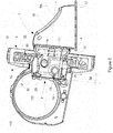
- Figure 3 illustrates a perspective and partial view of a protruding portion of a frame of the wind turbine of Figure 1 according to one example.
- the outer structure 12 and the inner structure 13 are concentrically positioned about the rotation axis RA, the inner structure 13 is positioned between the outer structure 12 and the rotation axis RA.
- the example illustrated in Figure 2 shows the outer structure 12 and the inner structure 13 having a drum-like shape, alternatively the outer structure 12 as second structure or the inner structure 13 as first structure may be formed by a plurality of connecting arms disposed around the rotation axis RA.
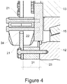
- Figure 4 shows a partial cross-section view of a brake system and a protruding portion of the frame of the wind turbine of Figure 1 according to one example.
- the brake system 2 may comprise a disc 21 and a calliper 22, the disc 21 may be attached to one of the first and second structures and the calliper 22 may be attached to the other one.
- the disc 21 may be attached to the second structure and the calliper 22 may be attached to the first structure.
- the disc 21 may be generally "ring-shaped" and may be manufactured from a metallic material or the like.
- the disc 21 is attached to the outer structure 12 and the caliper 22 to the inner structure 13.
- the disc 21 may be attached to the inner structure 13 and the calliper 22 to the outer structure 12.
- the brake system 2 may have a plurality of callipers circularly provided around the rotational axis RA.
- the callipers 22 may be regularly placed relative to the disc 21.
- Calliper 22 may have a number of pads configured to cause friction between the calliper 22 and the disc 21 to at least reduce, maintain or increase the rotational speed of the outer structure 12. The calliper may therefore clamp the disc 21.
- the outer structure 12 may rotate substantially faster, slower or the rotational speed may be unchanged.
- the brake system 2 may be used as a stationary parking brake to substantially prevent rotational movement of the outer structure 12 with respect to the inner structure 13.
- the rotational speed of the outer structure 12 may be kept unchanged and substantially null.
- the brake system 2 may be used to control rotational movement of the outer structure 12 with respect to the inner structure 13. For instance, a substantially constant rotational speed of the outer structure 12 may be produced.
- the calliper 22 may be disposed between the rotation axis RA and the disc 21. This way, the diameter of the disc 21 may be increased outwardly from the rotation axis RA.
- the size of the calliper 22 may be chosen to match the size of the cross-section of a larger disc 21.
- the calliper 22 may be operatively connected to the generator stator 32 through the first structure of the frame 1 and the disc 21 may be operatively connected to the generator rotor 31 through the second structure.
- the brake system 2 may act on the generator rotor 31. When the brake system 2 is operated, it may make the generator rotor 31 slow down.
- the disc 21 may be disposed between the rotation axis RA and the calliper 22.
- the disc 21 may be attached to the inner structure 13 and the calliper 22 to the outer structure 12.
- the calliper 22 may have a U-shaped cross-section to receive the cross section of the disc 21.
- a cavity 24 defined by the U-shaped cross-section of the calliper 22 may be facing outwardly from the rotation axis RA.
- the cavity 24 may receive at least a portion of the cross section of the disc 21.
- the disc 21 may be attached to the second structure through spacers 23.
- the distance 50 may be increased by a spacing 51 between the disc 21 and the second structure, e.g. outer structure 12.
- the spacers 23 may increase further the distance 50 between the brake system 2 and the generator 3.
- the spacers 23 may be chosen to adjust the clearance between the protruding portion 11 and the brake system 2 along the rotation axis RA. An increased clearance may allow installing a larger brake system 2, particularly a larger calliper 22.
- the brake system 2 may be driven by a hydraulic system to act on pads of the calliper 22 to exert pressure on the disc 21.
- the hydraulic system may have a pump, a pressure reservoir or the like in fluid communication with pistons to apply a force to the pads.
- the controller 180 may send a command to the pump or pressure reservoir to increase or decrease or maintain pressure of the fluid of the hydraulic system and thus to transfer pressure from the fluid to the pistons and so to the pads of the calliper 22.
- the brake system 2 may be based on electromechanical technology.
- an electric actuator linked to the calliper 22 may receive the corresponding command from the controller 180 to control the friction exerted to the disc 21 and so the rotational speed of the outer structure 12.
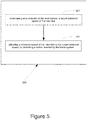
- FIG 5 shows a flowchart of a method 200 for braking a direct-drive wind turbine according to one example.
- the wind turbine 160 may be that one illustrated in Figures 1 or 2 and thus it includes the wind turbine controller 180.
- a method 200 for braking a direct-drive wind turbine 160 comprises: a rotor hub 110 and a generator 3 mounted on a frame 1.
- the wind turbine 160 further comprises a brake system 2.
- the frame has a protruding portion 11 extending beyond the generator 3.
- the protruding portion 11 comprises first and second structures configured to rotate relative to each other and about a rotation axis RA.
- the first structure is attached to a generator stator 32 and the second structure is attached to a generator rotor 31, the brake system 2 being attached to the first and second structures and the brake system 2 being spaced away from the generator 3 along the rotation axis RA.
- the method 200 comprises determining 201, at the controller 180 of the wind turbine 160, a target rotational speed of the rotor hub 110.
- the method 200 further comprises adjusting 202 a rotational speed of the rotor hub 110 to the target rotational speed by controlling the friction exerted by a braking system 2.
- it may further comprise applying friction with a calliper to the disc 21 attached to the second structure until a rotation of the rotor hub 110 is stopped.
- the rotation may be stopped with respect to the rotation axis RA.
- Braking moment may be obtained by the method 200 stepwise or continuously.
- a rotational movement of the rotor hub 110 may be transmitted to the generator rotor 31 because they may be fastened through bolts 4.
- An amount of rotational movement, e.g. a turn, of the rotor hub 110 around the rotational axis RA may mean the same amount of rotational movement of the generator rotor 31 because it is a direct-drive wind turbine 100.
- the outer structure 12 may also rotate the same amount of rotational movement because it is attached to the generator rotor 31, for instance through bolts 4. Thus, the outer structure 12 may rotate relative to the inner structure 13.
- the disc 21 is attached to the outer structure 12 and the callipers 22 are attached to the inner structure 13. Therefore, if the rotor hub 110 is turning around the rotational axis RA, disc 21 does it as well.
- the controller 180 determines a target rotational speed of the rotor hub 110.
- the rotational speed of the rotor hub 110 may be compared with the target rotational speed, for instance by the controller 180. Depending on this comparison the friction to the disc 21, which is controlled by the controller 180, may be reduced, increased or maintained.
- the controller 180 may trigger the brake system 2 to substantially increase or decrease the friction to the disc 21 to adjust the rotational speed. If a difference between the rotational speed of the rotor hub 110 and the target rotational speed is within a predetermined range, the controller 180 may trigger the brake system 2 to substantially maintain the friction to the disc 21.
- the calliper 22 may exert pressure on the disc 21 to generate friction. Therefore, the rotational speed of generator rotor 31 and outer structure 12 may be increased, reduced, maintained or even they may be stopped depending on the friction generated between disc 21 and callipers 22. Depending on the amount of exerted pressure on the disc 21 the rotational speed of the rotor hub 110, may be adjusted, e.g. increased, maintained, reduced or even stopped.
- An increased amount of friction may mean a reduction in rotational speed
- a decreased amount of friction may mean an increase in rotational speed
- an unchanged amount of friction may mean an unchanged rotational speed.
- the above exemplary braking operation has been depicted regarding two scenarios: the first one in which the rotor 115 is already rotating about the rotational axis RA and the brake system 2 is actuated then.
- the brake system 2 may be actuated when the rotor 115 is already stopped or at least when no rotational movement is substantially defined. The latter may occur for instance when the wind turbine 2 is broken-down or maintenance tasks must be performed. This way, a stopped status of the rotor 115 may be assured.
- a direct-drive wind turbine 160 comprises a rotor hub 110 having a hollow body and a generator 3 mounted on a frame 1 about a rotation axis RA.
- the generator 3 has a generator rotor 31 and a generator stator 32.
- the frame 1 has a protruding portion 11 extending beyond the generator 3 into the hollow body of the rotor hub 110.
- the protruding portion 11 comprises a stationary inner structure 13 attached to the generator stator 32.
- the protruding portion 11 further comprises an outer structure 12 which is configured to rotate about the rotation axis RA and is attached to the generator rotor 31.
- the direct-drive wind turbine 160 further comprises a brake system 2 comprising a disc 21 attached to one of the outer structure 12 and the inner structure 13 and a calliper 22 attached to the other of the outer structure 12 and the inner structure 13.
- the disc 21 may be attached to the outer structure 12 and the calliper 22 may be attached to the inner structure 13. In another example, the disc 21 may be attached to the inner structure 13 and the calliper 22 may be attached to the outer structure 12.
- the outer structure 12 and the inner structure 13 may be concentrically positioned about the rotation axis RA, the inner structure 13 may be positioned between the outer structure 12 and the rotation axis RA.
- the inner structure may have a tapered region 18 towards the hollow body of the rotor hub 110, the outer structure 12 may be rotatably mounted on the tapered region.
- the brake system 2 may be spaced away from the generator 3 along the rotation axis RA.
Landscapes
- Engineering & Computer Science (AREA)
- Life Sciences & Earth Sciences (AREA)
- Sustainable Development (AREA)
- Sustainable Energy (AREA)
- Chemical & Material Sciences (AREA)
- Combustion & Propulsion (AREA)
- Mechanical Engineering (AREA)
- General Engineering & Computer Science (AREA)
- Power Engineering (AREA)
- Wind Motors (AREA)
- Structures Of Non-Positive Displacement Pumps (AREA)
Abstract
Description
- The present disclosure relates to direct-drive wind turbines and methods for braking such direct-drive wind turbines.
- Modern wind turbines are commonly used to supply electricity into the electrical grid. Wind turbines of this kind generally comprise a tower and a rotor arranged on the tower. The rotor, which typically comprises a hub and a plurality of blades, is set into rotation under the influence of the wind on the blades. Said rotation generates a torque that is normally transmitted through a rotor shaft to a generator, either directly ("directly driven" or "gearless") or through the use of a gearbox. This way, the generator produces electricity which can be supplied to the electrical grid.
- In conventional wind turbines, the gearbox increases the speed of the wind-driven rotor. This reduces the required size of the generator. In the directly driven generators typically used in offshore direct-drive wind turbines, the rotor shaft is generally directly connected to the rotor hub. Direct-drive wind turbines thus comprise generators operating at the same rotational speed as the rotor with wind turbine blades and therefore having a much larger diameter than generators used in wind turbines having a gearbox.
- One challenging topic of the direct-drive wind turbines is related to the rotor brake system. As there is no gearbox, a relatively large braking moment is required to reduce the speed of the rotor, so the features of the brake system have to be chosen to withstand the braking moment. This issue is becoming more and more important because there is a trend to make wind turbines increasingly larger to capture more wind and convert the energy of the wind into electricity. The larger wind turbines may require a bigger braking moment and the bigger braking moment may involve increasing the size of the rotor brake systems.
- Due to space limitations, the usual location of the rotor brake system in a direct-drive wind turbine is in the generator to act between the generator stator and the generator rotor. However, the current arrangement of the brake system in the generator limits the size that can be achieved by the brake system.
- Furthermore, and regarding the usual arrangement of the brake system in the generator, if brake callipers are of a hydraulic type, there is a significant risk of leaking oil reaching the air gap of the generator.
- Additionally, evacuation route inside the generator is compromised by the brake callipers interfering with the minimum clearance required according to safety standard.
- Moreover, accessibility to component exchange, particularly in generator, is significantly reduced by the presence of the brake system in the generator.
- The present disclosure provides examples of direct-drive wind turbines and methods that at least partially resolve some of the aforementioned disadvantages.
- In one aspect, a direct-drive wind turbine is provided. The direct-drive wind turbine comprises a generator mounted on a frame, the generator comprising a generator stator and a generator rotor configured to rotate about a rotation axis, the frame has a protruding portion extending beyond the generator, the protruding portion comprising a first structure and a second structure. The first and second structure are configured to rotate relative to each other and about the rotation axis. The first structure is attached to the generator stator and the second structure is attached to the generator rotor. The direct-drive wind turbine further comprises a brake system attached to the first and second structures, the brake system being spaced away from the generator along the rotation axis.
- In this aspect, typical space limitations or constraints of the generator may be avoided. Integration of the brake system inside a direct-drive wind turbine may be facilitated. The size of the brake system, e.g. the calipers, may also be increased and so the obtained braking moment. Thus, the direct-drive wind turbine may be designed with a relatively larger size to capture more wind and convert the energy of the wind into electricity.
- Furthermore, an evacuation route inside the generator may not be compromised in the direct-drive wind turbine of this aspect by the brake system because a minimum required clearance may be obtained. Therefore, safety conditions may be enhanced.
- Moreover, as the brake system may be spaced apart from the generator, the risk of leaking oil reaching the air gap of the generator may be avoided.
- Additionally, an enhanced accessibility to component exchange of the direct-drive wind turbine, particularly the generator, may be obtained. This may mean easier maintenance or repair tasks and reducing the involved time.
- The ergonomics for the operators inside the nacelle is also enhanced thanks to the features of this first aspect.
- In another aspect, a method for braking a direct-drive wind turbine is provided. The wind turbine comprises a rotor hub, a generator mounted on a frame, and a brake system, the frame having a protruding portion extending beyond the generator, the protruding portion comprising first and second structures configured to rotate relative to each other and about a rotation axis, wherein the first structure is attached to a generator stator and the second structure is attached to a generator rotor, the brake system being attached to the first and second structures and the brake system being spaced away from the generator along the rotation axis. The method comprises determining at a controller of the wind turbine, a target rotational speed of the rotor hub, and adjusting a rotational speed of the rotor hub to the target rotational speed by controlling a friction exerted by the brake system .
- In yet another aspect, a direct-drive wind turbine is provided. The direct-drive wind turbine comprises a rotor hub having a hollow body, a generator mounted on a frame about a rotation axis, the generator having a generator rotor and a generator stator. The frame has a protruding portion extending beyond the generator into the hollow body of the rotor hub. The protruding portion comprises a stationary inner structure attached to the generator stator; an outer structure which is configured to rotate about the rotation axis and is attached to the generator rotor. The direct-drive wind turbine further comprises: a brake system comprising a disc attached to one of the outer structure and the inner structure and a calliper attached to the other of the outer structure and the inner structure.
- Advantages derived from this aspect may be similar to those mentioned regarding the direct-drive wind turbine of the first aspect.
- Non-limiting examples of the present disclosure will be described in the following, with reference to the appended drawings, in which:
-
Figure 1 illustrates a perspective view of a wind turbine according to one example; -
Figure 2 illustrates a simplified, internal cross-sectional view of a nacelle and a rotor hub of a wind turbine according to one example; -
Figure 3 illustrates a perspective and partial view of a protruding portion of a frame of the wind turbine ofFigure 1 according to one example; -
Figure 4 shows a partial cross-section view of a brake system and a protruding portion of the frame of the wind turbine ofFigure 1 according to one example; and -
Figure 5 shows a flowchart of a method for braking a direct-drive wind turbine according to one example. - In these figures the same reference signs have been used to designate matching elements.
-
Figure 1 illustrates a perspective view of one example of awind turbine 160. As shown, thewind turbine 160 includes atower 170 extending from asupport surface 150, anacelle 161 mounted on thetower 170, and arotor 115 coupled to thenacelle 161. Therotor 115 includes arotatable rotor hub 110 and at least onerotor blade 120 coupled to and extending outwardly from therotor hub 110. For example, in the illustrated example, therotor 115 includes threerotor blades 120. However, in an alternative embodiment, therotor 115 may include more or less than threerotor blades 120. Eachrotor blade 120 may be spaced from therotor hub 110 to facilitate rotating therotor 115 to enable kinetic energy to be transferred from the wind into usable mechanical energy, and subsequently, electrical energy. For instance, therotor hub 110 may be rotatably coupled to an electric generator 3 (Figure 2 ) positioned within thenacelle 161 or forming part of the nacelle to permit electrical energy to be produced. - The
wind turbine 160 may also include awind turbine controller 180 centrally located within thenacelle 161. However, in other examples, thewind turbine controller 180 may be located within any other component of thewind turbine 160 or at a location outside the wind turbine. Further, thecontroller 180 may be communicatively coupled to any number of components of thewind turbine 160 in order to control the operation of such components. - The
wind turbine 160 ofFigure 1 may be placed in an offshore or onshore location. - The
wind turbine controller 180 may include one or more processor(s) and associated memory device(s) configured to perform a variety of computer-implemented functions (e.g., performing the methods, steps, calculations and the like and storing relevant data as disclosed herein). The wind turbine controller may perform various different functions, such as receiving, transmitting and/or executing wind turbine control signals and controlling the overall operation of the wind turbine. The wind turbine controller may be programmed to control the overall operation based on information received from sensors indicating e.g. loads, wind speed, wind direction, turbulence failure of a component and other. - As used herein, the term "processor" refers not only to integrated circuits referred to in the art as being included in a computer, but also refers to a controller, a microcontroller, a microcomputer, a programmable logic controller (PLC), an application specific integrated circuit, and other programmable circuits. The processor is also configured to compute advanced control algorithms and communicate to a variety of Ethernet or serial-based protocols (Modbus, OPC, CAN, etc.). Additionally, the memory device(s) may comprise memory element(s) including, but not limited to, computer readable medium (e.g., random access memory (RAM)), computer readable non-volatile medium (e.g., a flash memory), a floppy disk, a compact disc-read only memory (CD-ROM), a magneto-optical disk (MOD), a digital versatile disc (DVD) and/or other suitable memory elements. Such memory device(s) may be configured to store suitable computer-readable instructions that, when implemented by the processor(s), configure the controller to perform the various functions as described herein.
-
Figure 2 illustrates a simplified, internal cross-sectional view of thenacelle 161 and therotor hub 110 of a wind turbine according to one example. Some elements of thewind turbine 160 have not been illustrated for the sake of clarity. As shown, thegenerator 3 may be coupled to therotor hub 110 of thewind turbine 160 for generating electrical power from the rotational energy generated. Thus, rotation of therotor hub 110 drives thegenerator 3. - It should be appreciated that
frame 1 andgenerator 3 may generally be supported within thenacelle 161 by a support frame orbedplate 17 positioned atop thewind turbine tower 170. Thenacelle 161 is rotatably coupled to thetower 170. Thebedplate 17 may be rotatably coupled to a wind turbine tower - According to one aspect, a direct-
drive wind turbine 160 as perFigures 1 and2 is disclosed. Thewind turbine 160 comprises agenerator 3 mounted on aframe 1. Thegenerator 3 comprises agenerator stator 32 and agenerator rotor 31 configured to rotate about a rotation axis RA. Theframe 1 has a protrudingportion 11 extending beyond thegenerator 3. The protrudingportion 11 comprises a first structure and a second structure. The first and second structures are configured to rotate relative to each other and about the rotation axis RA. The first structure is attached to thegenerator stator 32 and the second structure is attached to thegenerator rotor 31. Thewind turbine 160 further comprises abrake system 2 attached to the first and second structures. The brake system is spaced away from thegenerator 3 along the rotation axis RA. - Terms first structure and second structure as used herein may be interchangeable.
- In the example illustrated in
Figure 2 , the protrudingportion 11 extends towards therotor hub 110 of thewind turbine 160 along the rotation axis RA. Thus, the protrudingportion 11 may extend in an upwind direction along the rotation axis RA. - In another example, the protruding portion may extend away from the
rotor hub 110 of thewind turbine 160 along the rotation axis RA. The protrudingportion 11 may extend towards thebed plate 17 ortower 170, i.e. the protrudingportion 11 may be positioned in an opposite direction to therotor hub 110 along the rotation axis RA. Therefore, the protrudingportion 11 may extend in a downwind direction along the rotation axis RA. - A
distance 50 may be defined between thegenerator 3 and thebrake system 2, i.e. thebrake system 2 can be placed spaced apart from thegenerator 3 or even a housing or cover of thegenerator 3. Thedistance 50 can be clearly seen inFigure 2 , where thebrake system 2 is positioned at adistal end 19 of the protrudingportion 11, thedistal end 19 of the protrudingportion 11 being positioned away from thegenerator 3 along the rotation axis RA.Distance 50 may also be defined when the protrudingportion 11 extends towards thebed plate 17 or thetower 170. - Referring to
Figure 2 , the protrudingportion 11 may be a front portion of theframe 1. In this case, theframe 1 may have arear portion 16 facing towards thebedplate 17 of thewind turbine 160. - In one example, the first structure may be an
inner structure 13 and the second structure may be anouter structure 12. This example can be seen inFigure 2 . In another example, the first structure may be an outer structure and the second structure may be an inner structure. In both examples the inner and the outer structure may rotate relative to each other and about the rotation axis RA. - According to one example of the direct-
drive wind turbine 160, theouter structure 12 may be operatively connected to therotor hub 110 through thegenerator rotor 31. The latter may be achieved, for instance, through a series ofbolts 4 as shown inFigure 2 . Thebolts 4 are joining together therotor hub 110, theouter structure 12 and thegenerator rotor 31 in such a way that at least a part of thegenerator rotor 31 is sandwiched by therotor hub 110 and theouter structure 12. This exemplary joint may allow to transmit the rotating movement of therotor hub 110 to theouter structure 12 through thegenerator rotor 31. Conversely, if theouter structure 12, for example, is braked then thegenerator rotor 31 and therotor hub 110 may be braked as well. - In another example, the joint may be achieved through any fasteners available on the market or even through welding.
- As shown in
Figure 2 , the first structure may have a taperedregion 18 towards therotor hub 110. The second structure may be rotatably mounted on the taperedregion 18, i.e. the second structure can rotate about the rotation axis RA and the first structure. The taperedregion 18 may protrude from thegenerator 3, at least partially, towards therotor hub 110. - As illustrated, the direct-
drive wind turbine 160 may further comprise a pair ofbearings 15 between the second structure, e.g.outer structure 12, and the first structure, e.g.inner structure 13. The pair ofbearings 15 may be spaced apart each other along the rotational axis RA. Alternatively, a single bearing may rotatably connect the first structure and the second structure. - Following with the example of
Figure 2 , at least a part of the protrudingportion 11 may be placed in aroom 111 defined inside therotor hub 110. Theroom 111 may provide enough space to choose thebrake system 2 with a significantly large size. Theroom 111 may be defined as the hollow body of therotor hub 110. - In
Figure 2 , thegenerator rotor 31 surrounds thegenerator stator 32. However, in other examples, the generator stator may surround the generator rotor. In these other examples, the generator rotor may be associated with the rotor hub and the stator generator may be associated with the inner structure like any of the examples herein disclosed with respect to a generator rotor surrounding the generator stator. -
Figure 3 illustrates a perspective and partial view of a protruding portion of a frame of the wind turbine ofFigure 1 according to one example. As shown inFigures 2 and3 , theouter structure 12 and theinner structure 13 are concentrically positioned about the rotation axis RA, theinner structure 13 is positioned between theouter structure 12 and the rotation axis RA. Although the example illustrated inFigure 2 shows theouter structure 12 and theinner structure 13 having a drum-like shape, alternatively theouter structure 12 as second structure or theinner structure 13 as first structure may be formed by a plurality of connecting arms disposed around the rotation axis RA. -
Figure 4 shows a partial cross-section view of a brake system and a protruding portion of the frame of the wind turbine ofFigure 1 according to one example. - In one example, the
brake system 2 may comprise adisc 21 and acalliper 22, thedisc 21 may be attached to one of the first and second structures and thecalliper 22 may be attached to the other one. In a specific example, thedisc 21 may be attached to the second structure and thecalliper 22 may be attached to the first structure. In both cases, thedisc 21 may be generally "ring-shaped" and may be manufactured from a metallic material or the like. - Referring now to the examples of
Figures 3 and4 , it can be seen that thedisc 21 is attached to theouter structure 12 and thecaliper 22 to theinner structure 13. In another example, thedisc 21 may be attached to theinner structure 13 and thecalliper 22 to theouter structure 12. - In some other examples, the
brake system 2 may have a plurality of callipers circularly provided around the rotational axis RA. Thecallipers 22 may be regularly placed relative to thedisc 21.Calliper 22 may have a number of pads configured to cause friction between thecalliper 22 and thedisc 21 to at least reduce, maintain or increase the rotational speed of theouter structure 12. The calliper may therefore clamp thedisc 21. Thus, theouter structure 12 may rotate substantially faster, slower or the rotational speed may be unchanged. - Furthermore, the
brake system 2 may be used as a stationary parking brake to substantially prevent rotational movement of theouter structure 12 with respect to theinner structure 13. In this case, the rotational speed of theouter structure 12 may be kept unchanged and substantially null. - Moreover, the
brake system 2 may be used to control rotational movement of theouter structure 12 with respect to theinner structure 13. For instance, a substantially constant rotational speed of theouter structure 12 may be produced. - As shown in
Figure 3 , thecalliper 22 may be disposed between the rotation axis RA and thedisc 21. This way, the diameter of thedisc 21 may be increased outwardly from the rotation axis RA. The size of thecalliper 22 may be chosen to match the size of the cross-section of alarger disc 21. - In an example of the direct-
drive wind turbine 160, thecalliper 22 may be operatively connected to thegenerator stator 32 through the first structure of theframe 1 and thedisc 21 may be operatively connected to thegenerator rotor 31 through the second structure. This way, thebrake system 2 may act on thegenerator rotor 31. When thebrake system 2 is operated, it may make thegenerator rotor 31 slow down. - In another example, the
disc 21 may be disposed between the rotation axis RA and thecalliper 22. In this example, thedisc 21 may be attached to theinner structure 13 and thecalliper 22 to theouter structure 12. - Following with the examples of
Figures 3 and4 , thecalliper 22 may have a U-shaped cross-section to receive the cross section of thedisc 21. Acavity 24 defined by the U-shaped cross-section of thecalliper 22 may be facing outwardly from the rotation axis RA. Thecavity 24 may receive at least a portion of the cross section of thedisc 21. - Referring now to
Figure 4 thedisc 21 may be attached to the second structure throughspacers 23. Thedistance 50 may be increased by a spacing 51 between thedisc 21 and the second structure, e.g.outer structure 12. Thespacers 23 may increase further thedistance 50 between thebrake system 2 and thegenerator 3. Thespacers 23 may be chosen to adjust the clearance between the protrudingportion 11 and thebrake system 2 along the rotation axis RA. An increased clearance may allow installing alarger brake system 2, particularly alarger calliper 22. - In some examples, the
brake system 2 may be driven by a hydraulic system to act on pads of thecalliper 22 to exert pressure on thedisc 21. The hydraulic system may have a pump, a pressure reservoir or the like in fluid communication with pistons to apply a force to the pads. In order to control thebrake system 2, thecontroller 180 may send a command to the pump or pressure reservoir to increase or decrease or maintain pressure of the fluid of the hydraulic system and thus to transfer pressure from the fluid to the pistons and so to the pads of thecalliper 22. - In alternative examples, the
brake system 2 may be based on electromechanical technology. Instead of the hydraulic system, an electric actuator linked to thecalliper 22 may receive the corresponding command from thecontroller 180 to control the friction exerted to thedisc 21 and so the rotational speed of theouter structure 12. -
Figure 5 shows a flowchart of amethod 200 for braking a direct-drive wind turbine according to one example. Thewind turbine 160 may be that one illustrated inFigures 1 or2 and thus it includes thewind turbine controller 180. - According to an aspect, a
method 200 for braking a direct-drive wind turbine 160 is provided. Thewind turbine 160 comprises: arotor hub 110 and agenerator 3 mounted on aframe 1. Thewind turbine 160 further comprises abrake system 2. The frame has a protrudingportion 11 extending beyond thegenerator 3. The protrudingportion 11 comprises first and second structures configured to rotate relative to each other and about a rotation axis RA. The first structure is attached to agenerator stator 32 and the second structure is attached to agenerator rotor 31, thebrake system 2 being attached to the first and second structures and thebrake system 2 being spaced away from thegenerator 3 along the rotation axis RA. Themethod 200 comprises determining 201, at thecontroller 180 of thewind turbine 160, a target rotational speed of therotor hub 110. Themethod 200 further comprises adjusting 202 a rotational speed of therotor hub 110 to the target rotational speed by controlling the friction exerted by abraking system 2. - In some examples of the
method 200, it may further comprise applying friction with a calliper to thedisc 21 attached to the second structure until a rotation of therotor hub 110 is stopped. The rotation may be stopped with respect to the rotation axis RA. - Braking moment may be obtained by the
method 200 stepwise or continuously. - In an exemplary operation, a rotational movement of the
rotor hub 110 may be transmitted to thegenerator rotor 31 because they may be fastened throughbolts 4. An amount of rotational movement, e.g. a turn, of therotor hub 110 around the rotational axis RA may mean the same amount of rotational movement of thegenerator rotor 31 because it is a direct-drive wind turbine 100. Theouter structure 12 may also rotate the same amount of rotational movement because it is attached to thegenerator rotor 31, for instance throughbolts 4. Thus, theouter structure 12 may rotate relative to theinner structure 13. In the example ofFigures 2 or3 thedisc 21 is attached to theouter structure 12 and thecallipers 22 are attached to theinner structure 13. Therefore, if therotor hub 110 is turning around the rotational axis RA,disc 21 does it as well. - The
controller 180 determines a target rotational speed of therotor hub 110. The rotational speed of therotor hub 110 may be compared with the target rotational speed, for instance by thecontroller 180. Depending on this comparison the friction to thedisc 21, which is controlled by thecontroller 180, may be reduced, increased or maintained. By way of example, if a difference between the rotational speed of therotor hub 110 and the target rotational speed is out of a predetermined range, thecontroller 180 may trigger thebrake system 2 to substantially increase or decrease the friction to thedisc 21 to adjust the rotational speed. If a difference between the rotational speed of therotor hub 110 and the target rotational speed is within a predetermined range, thecontroller 180 may trigger thebrake system 2 to substantially maintain the friction to thedisc 21. - The
calliper 22 may exert pressure on thedisc 21 to generate friction. Therefore, the rotational speed ofgenerator rotor 31 andouter structure 12 may be increased, reduced, maintained or even they may be stopped depending on the friction generated betweendisc 21 andcallipers 22. Depending on the amount of exerted pressure on thedisc 21 the rotational speed of therotor hub 110, may be adjusted, e.g. increased, maintained, reduced or even stopped. An increased amount of friction may mean a reduction in rotational speed, a decreased amount of friction may mean an increase in rotational speed and an unchanged amount of friction may mean an unchanged rotational speed. - The above exemplary braking operation has been depicted regarding two scenarios: the first one in which the
rotor 115 is already rotating about the rotational axis RA and thebrake system 2 is actuated then. In the second one, thebrake system 2 may be actuated when therotor 115 is already stopped or at least when no rotational movement is substantially defined. The latter may occur for instance when thewind turbine 2 is broken-down or maintenance tasks must be performed. This way, a stopped status of therotor 115 may be assured. - According to a yet another aspect, a direct-
drive wind turbine 160 is provided. Thewind turbine 160 of this aspect comprises arotor hub 110 having a hollow body and agenerator 3 mounted on aframe 1 about a rotation axis RA. Thegenerator 3 has agenerator rotor 31 and agenerator stator 32. Theframe 1 has a protrudingportion 11 extending beyond thegenerator 3 into the hollow body of therotor hub 110. The protrudingportion 11 comprises a stationaryinner structure 13 attached to thegenerator stator 32. The protrudingportion 11 further comprises anouter structure 12 which is configured to rotate about the rotation axis RA and is attached to thegenerator rotor 31. The direct-drive wind turbine 160 further comprises abrake system 2 comprising adisc 21 attached to one of theouter structure 12 and theinner structure 13 and acalliper 22 attached to the other of theouter structure 12 and theinner structure 13. - In one example, the
disc 21 may be attached to theouter structure 12 and thecalliper 22 may be attached to theinner structure 13. In another example, thedisc 21 may be attached to theinner structure 13 and thecalliper 22 may be attached to theouter structure 12. - According to one example of this aspect, the
outer structure 12 and theinner structure 13 may be concentrically positioned about the rotation axis RA, theinner structure 13 may be positioned between theouter structure 12 and the rotation axis RA. - In another example, the inner structure may have a tapered
region 18 towards the hollow body of therotor hub 110, theouter structure 12 may be rotatably mounted on the tapered region. - In a further example, the
brake system 2 may be spaced away from thegenerator 3 along the rotation axis RA. - This written description uses examples to disclose the invention, including the preferred embodiments, and also to enable any person skilled in the art to practice the invention, including making and using any devices or systems and performing any incorporated methods. The patentable scope of the invention is defined by the claims, and may include other examples that occur to those skilled in the art. Such other examples are intended to be within the scope of the claims if they have structural elements that do not differ from the literal language of the claims, or if they include equivalent structural elements with insubstantial differences from the literal languages of the claims. Aspects from the various embodiments described, as well as other known equivalents for each such aspects, can be mixed and matched by one of ordinary skill in the art to construct additional embodiments and techniques in accordance with principles of this application. If reference signs related to drawings are placed in parentheses in a claim, they are solely for attempting to increase the intelligibility of the claim, and shall not be construed as limiting the scope of the claim.
Claims (15)
- A direct-drive wind turbine (160) comprising:a generator (3) mounted on a frame (1), the generator (3) comprising a generator stator (32) and a generator rotor (31) configured to rotate about a rotation axis (RA), the frame (1) has a protruding portion (11) extending beyond the generator (3), the protruding portion (11) comprising a first structure and a second structure; wherein the first and second structures are configured to rotate relative to each other and about the rotation axis (RA); wherein the first structure is attached to the generator stator (32) and the second structure is attached to the generator rotor (31);a brake system (2) attached to the first and second structures, the brake system (2) being spaced away from the generator (3) along the rotation axis (RA).
- The direct-drive wind turbine (160) according to claim 1, wherein the protruding portion (11) extends towards a rotor hub (110) of the wind turbine along the rotation axis (RA).
- The direct-drive wind turbine (160) according to claim 1, wherein the protruding portion (11) extends away from a rotor hub (110) of the wind turbine along the rotation axis (RA).
- The direct-drive wind turbine (160) according to claim 1, wherein the first structure is an inner structure (11) and the second structure is an outer structure (12).
- The direct-drive wind turbine (160) according to claim 4, wherein the outer structure (12) and the inner structure (13) are concentrically positioned about the rotation axis (RA), the inner structure (13) being positioned between the outer structure (12) and the rotation axis (RA).
- The direct-drive wind turbine (160) according to claim 1, wherein the first structure is an outer structure and the second structure is an inner structure.
- The direct-drive wind turbine (160) according to any of claims 1 - 6, wherein the brake system (2) comprises a disc (21) and a calliper (22), the disc (21) being attached to one of the first and second structures and the calliper (22) being attached to the other one.
- The direct-drive wind turbine (160) according to claim 7, wherein the disc (21) is attached to the second structure and the calliper (22) is attached to the first structure.
- The direct-drive wind turbine (160) according to claim 8, wherein the calliper (22) is disposed between the rotation axis (RA) and the disc (21).
- The direct-drive wind turbine (160) according to any of claims 7 - 9, wherein the calliper (22) has a U-shaped cross-section to receive the cross section of the disc (21), and a cavity (24) defined by the U-shaped cross-section of the calliper (22) is facing outwardly from the rotation axis (RA).
- The direct-drive wind turbine (160) according to claim 8, wherein the disc (21) is attached to the second structure (12) through spacers (23).
- The direct-drive wind turbine (160) according to claim 1, wherein the brake system (2) is positioned at a distal end of the protruding portion (11), the distal end of the protruding portion (11) being positioned spaced away from the generator (3) along the rotation axis (RA).
- The direct-drive wind turbine (160) according to any of claims 7 - 11, wherein the calliper (22) is operatively connected to the generator stator (32) through the first structure of the frame (1) and the disc (21) is operatively connected to the generator rotor (31) through the second structure.
- The direct-drive wind turbine (160) according to claim 2, wherein the first structure has a tapered region (18) towards a rotor hub (110), the second structure being rotatably mounted on the tapered region (18).
- A method (200) for braking a direct-drive wind turbine (160), comprising a rotor hub (110), a generator (3) mounted on a frame (1), and a brake system (2), the frame (1) having a protruding portion (11) extending beyond the generator (3), the protruding portion (11) comprising first and second structures configured to rotate relative to each other and about a rotation axis (RA), wherein the first structure is attached to a generator stator (32) and the second structure is attached to a generator rotor (31), the brake system (2) being attached to the first and second structures and the brake system (2) being spaced away from the generator (3) along the rotation axis (RA); the method comprising:determining (201) at a controller (180) of the wind turbine (160), a target rotational speed of the rotor hub (110);adjusting (202) a rotational speed of the rotor hub to the target rotational speed by controlling a friction exerted by the brake system (2).
Priority Applications (5)
| Application Number | Priority Date | Filing Date | Title |
|---|---|---|---|
| ES19382647T ES2953435T3 (en) | 2019-07-29 | 2019-07-29 | Direct Drive Wind Turbine |
| EP19382647.6A EP3771821B1 (en) | 2019-07-29 | 2019-07-29 | Direct-drive wind turbine |
| PL19382647.6T PL3771821T3 (en) | 2019-07-29 | 2019-07-29 | Direct-drive wind turbine |
| US16/940,700 US11434877B2 (en) | 2019-07-29 | 2020-07-28 | Direct-drive wind turbine including multiple bearing sets and inner and outer frame structure members axially extending through a generator core for supporting the generator and rotor hub |
| CN202010743426.1A CN112302867B (en) | 2019-07-29 | 2020-07-29 | Direct drive wind turbine |
Applications Claiming Priority (1)
| Application Number | Priority Date | Filing Date | Title |
|---|---|---|---|
| EP19382647.6A EP3771821B1 (en) | 2019-07-29 | 2019-07-29 | Direct-drive wind turbine |
Publications (2)
| Publication Number | Publication Date |
|---|---|
| EP3771821A1 true EP3771821A1 (en) | 2021-02-03 |
| EP3771821B1 EP3771821B1 (en) | 2023-05-31 |
Family
ID=67480145
Family Applications (1)
| Application Number | Title | Priority Date | Filing Date |
|---|---|---|---|
| EP19382647.6A Active EP3771821B1 (en) | 2019-07-29 | 2019-07-29 | Direct-drive wind turbine |
Country Status (5)
| Country | Link |
|---|---|
| US (1) | US11434877B2 (en) |
| EP (1) | EP3771821B1 (en) |
| CN (1) | CN112302867B (en) |
| ES (1) | ES2953435T3 (en) |
| PL (1) | PL3771821T3 (en) |
Families Citing this family (3)
| Publication number | Priority date | Publication date | Assignee | Title |
|---|---|---|---|---|
| EP4105478B1 (en) | 2021-06-15 | 2025-07-30 | General Electric Renovables España S.L. | Supporting structures and methods for a central frame of a direct-drive wind turbine |
| EP4283117A1 (en) * | 2022-05-25 | 2023-11-29 | General Electric Renovables España S.L. | Assemblies for wind turbines and methods |
| EP4357613A1 (en) * | 2022-10-17 | 2024-04-24 | General Electric Renovables España S.L. | Drive train assemblies for wind turbines |
Citations (5)
| Publication number | Priority date | Publication date | Assignee | Title |
|---|---|---|---|---|
| DE102004031329A1 (en) * | 2004-06-29 | 2006-01-19 | Klinger, Friedrich, Prof. Dr. Ing. | External rotor for a generator in a wind power installation has an outer ring (OR) and a grouping with a permanent magnet of components following each other at a tangent on the OR inner side |
| EP1925820A1 (en) * | 2006-11-23 | 2008-05-28 | Harakosan Co. Ltd. | Wind turbine main bearing |
| CN201165940Y (en) * | 2007-11-07 | 2008-12-17 | 王光顺 | Permanent Magnet Direct Drive Wind Turbine |
| WO2014032826A1 (en) * | 2012-09-03 | 2014-03-06 | Wobben Properties Gmbh | Method and control device for a wind turbine, and computer program product, digital storage medium and wind turbine |
| DE102018100864A1 (en) * | 2018-01-16 | 2019-07-18 | Wobben Properties Gmbh | Wind turbine with a braking and locking device, stand assembly for selbige, and method for their operation |
Family Cites Families (5)
| Publication number | Priority date | Publication date | Assignee | Title |
|---|---|---|---|---|
| US7075192B2 (en) * | 2004-04-19 | 2006-07-11 | Northern Power Systems, Inc. | Direct drive wind turbine |
| EP2333321B1 (en) * | 2009-11-26 | 2016-06-15 | Siemens Aktiengesellschaft | Brake system with expansion absorbing means, generator and wind turbine |
| US20130099503A1 (en) * | 2011-10-25 | 2013-04-25 | General Electric Company | Lamination stack for an electrical machine stator |
| EP2747252B1 (en) * | 2012-12-18 | 2019-01-23 | Siemens Aktiengesellschaft | Air-gap secure system for a wind turbine |
| CN105226848A (en) * | 2015-09-29 | 2016-01-06 | 北京金风科创风电设备有限公司 | Generators and wind turbines |
-
2019
- 2019-07-29 PL PL19382647.6T patent/PL3771821T3/en unknown
- 2019-07-29 EP EP19382647.6A patent/EP3771821B1/en active Active
- 2019-07-29 ES ES19382647T patent/ES2953435T3/en active Active
-
2020
- 2020-07-28 US US16/940,700 patent/US11434877B2/en active Active
- 2020-07-29 CN CN202010743426.1A patent/CN112302867B/en active Active
Patent Citations (5)
| Publication number | Priority date | Publication date | Assignee | Title |
|---|---|---|---|---|
| DE102004031329A1 (en) * | 2004-06-29 | 2006-01-19 | Klinger, Friedrich, Prof. Dr. Ing. | External rotor for a generator in a wind power installation has an outer ring (OR) and a grouping with a permanent magnet of components following each other at a tangent on the OR inner side |
| EP1925820A1 (en) * | 2006-11-23 | 2008-05-28 | Harakosan Co. Ltd. | Wind turbine main bearing |
| CN201165940Y (en) * | 2007-11-07 | 2008-12-17 | 王光顺 | Permanent Magnet Direct Drive Wind Turbine |
| WO2014032826A1 (en) * | 2012-09-03 | 2014-03-06 | Wobben Properties Gmbh | Method and control device for a wind turbine, and computer program product, digital storage medium and wind turbine |
| DE102018100864A1 (en) * | 2018-01-16 | 2019-07-18 | Wobben Properties Gmbh | Wind turbine with a braking and locking device, stand assembly for selbige, and method for their operation |
Also Published As
| Publication number | Publication date |
|---|---|
| US11434877B2 (en) | 2022-09-06 |
| EP3771821B1 (en) | 2023-05-31 |
| PL3771821T3 (en) | 2023-10-09 |
| CN112302867B (en) | 2025-12-16 |
| CN112302867A (en) | 2021-02-02 |
| ES2953435T3 (en) | 2023-11-13 |
| US20210033073A1 (en) | 2021-02-04 |
Similar Documents
| Publication | Publication Date | Title |
|---|---|---|
| US11434877B2 (en) | Direct-drive wind turbine including multiple bearing sets and inner and outer frame structure members axially extending through a generator core for supporting the generator and rotor hub | |
| JP5092017B2 (en) | Wind power generator and nacelle turning method | |
| US9470208B2 (en) | Wind turbine and locking method | |
| EP2306008A2 (en) | Yaw bearing assembly for use with a wind turbine and a method for braking the yaw movement | |
| EP2159472A1 (en) | A fluidic system, a drive train for a wind turbine and a method for actuating a mechanical component | |
| EP2466124A2 (en) | Hydraulic yaw drive system for a wind turbine and method of operating the same | |
| CN104603453B (en) | Wind energy plant, method, adjusting means and digital storage media for its operation | |
| US20140010656A1 (en) | Fixation device | |
| US20130088009A1 (en) | Method to Prevent Over Torque of Yaw Drive Components in a Wind Turbine | |
| JP2011127551A (en) | Wind-powered generator apparatus | |
| EP3643915A1 (en) | System and method for application of a brake for a wind turbine | |
| CN103670923A (en) | System and method for braking a wind turbine rotor at an overspeed condition | |
| EP2485385A2 (en) | Method and system for testing a mechanical brake of a wind rotor shaft of a wind turbine | |
| US11608811B2 (en) | System and method for mitigating loads acting on a rotor blade of a wind turbine | |
| EP2402601A2 (en) | Apparatus and method for adjusting the yaw of a nacelle of a wind energy system | |
| US10612527B2 (en) | Methods for refurbishing wind turbines | |
| CA2896913C (en) | Method for adjusting the azimuth of a wind power plant, azimuth adjustment system and wind power plant | |
| EP3058219B1 (en) | System for pitch control | |
| CN104105873B (en) | Assembly for fixing a rotor blade of a wind power plant | |
| US12163505B2 (en) | Pitch systems for blades of wind turbines and associated methods | |
| CN103245453A (en) | Method and system for testing mechanical brake of wind rotor shaft of wind turbine | |
| WO2025088701A1 (en) | Wind power generation device | |
| KR20190071418A (en) | Vertical Wind Turbine System Equipped with Magnetic Brake | |
| AU2014323747A1 (en) | Rotor blade for a wind turbine, rotor hub, drive train, nacelle, wind turbine and wind turbine farm |
Legal Events
| Date | Code | Title | Description |
|---|---|---|---|
| PUAI | Public reference made under article 153(3) epc to a published international application that has entered the european phase |
Free format text: ORIGINAL CODE: 0009012 |
|
| STAA | Information on the status of an ep patent application or granted ep patent |
Free format text: STATUS: THE APPLICATION HAS BEEN PUBLISHED |
|
| AK | Designated contracting states |
Kind code of ref document: A1 Designated state(s): AL AT BE BG CH CY CZ DE DK EE ES FI FR GB GR HR HU IE IS IT LI LT LU LV MC MK MT NL NO PL PT RO RS SE SI SK SM TR |
|
| STAA | Information on the status of an ep patent application or granted ep patent |
Free format text: STATUS: REQUEST FOR EXAMINATION WAS MADE |
|
| 17P | Request for examination filed |
Effective date: 20210803 |
|
| RBV | Designated contracting states (corrected) |
Designated state(s): AL AT BE BG CH CY CZ DE DK EE ES FI FR GB GR HR HU IE IS IT LI LT LU LV MC MK MT NL NO PL PT RO RS SE SI SK SM TR |
|
| GRAP | Despatch of communication of intention to grant a patent |
Free format text: ORIGINAL CODE: EPIDOSNIGR1 |
|
| STAA | Information on the status of an ep patent application or granted ep patent |
Free format text: STATUS: GRANT OF PATENT IS INTENDED |
|
| INTG | Intention to grant announced |
Effective date: 20230202 |
|
| GRAS | Grant fee paid |
Free format text: ORIGINAL CODE: EPIDOSNIGR3 |
|
| GRAA | (expected) grant |
Free format text: ORIGINAL CODE: 0009210 |
|
| STAA | Information on the status of an ep patent application or granted ep patent |
Free format text: STATUS: THE PATENT HAS BEEN GRANTED |
|
| AK | Designated contracting states |
Kind code of ref document: B1 Designated state(s): AL AT BE BG CH CY CZ DE DK EE ES FI FR GB GR HR HU IE IS IT LI LT LU LV MC MK MT NL NO PL PT RO RS SE SI SK SM TR |
|
| REG | Reference to a national code |
Ref country code: GB Ref legal event code: FG4D Ref country code: CH Ref legal event code: EP |
|
| REG | Reference to a national code |
Ref country code: DE Ref legal event code: R096 Ref document number: 602019029517 Country of ref document: DE |
|
| REG | Reference to a national code |
Ref country code: AT Ref legal event code: REF Ref document number: 1571075 Country of ref document: AT Kind code of ref document: T Effective date: 20230615 |
|
| REG | Reference to a national code |
Ref country code: IE Ref legal event code: FG4D |
|
| P01 | Opt-out of the competence of the unified patent court (upc) registered |
Effective date: 20230529 |
|
| REG | Reference to a national code |
Ref country code: NL Ref legal event code: FP |
|
| REG | Reference to a national code |
Ref country code: LT Ref legal event code: MG9D |
|
| REG | Reference to a national code |
Ref country code: AT Ref legal event code: MK05 Ref document number: 1571075 Country of ref document: AT Kind code of ref document: T Effective date: 20230531 |
|
| PG25 | Lapsed in a contracting state [announced via postgrant information from national office to epo] |
Ref country code: SE Free format text: LAPSE BECAUSE OF FAILURE TO SUBMIT A TRANSLATION OF THE DESCRIPTION OR TO PAY THE FEE WITHIN THE PRESCRIBED TIME-LIMIT Effective date: 20230531 Ref country code: NO Free format text: LAPSE BECAUSE OF FAILURE TO SUBMIT A TRANSLATION OF THE DESCRIPTION OR TO PAY THE FEE WITHIN THE PRESCRIBED TIME-LIMIT Effective date: 20230831 Ref country code: AT Free format text: LAPSE BECAUSE OF FAILURE TO SUBMIT A TRANSLATION OF THE DESCRIPTION OR TO PAY THE FEE WITHIN THE PRESCRIBED TIME-LIMIT Effective date: 20230531 |
|
| REG | Reference to a national code |
Ref country code: ES Ref legal event code: FG2A Ref document number: 2953435 Country of ref document: ES Kind code of ref document: T3 Effective date: 20231113 |
|
| PG25 | Lapsed in a contracting state [announced via postgrant information from national office to epo] |
Ref country code: RS Free format text: LAPSE BECAUSE OF FAILURE TO SUBMIT A TRANSLATION OF THE DESCRIPTION OR TO PAY THE FEE WITHIN THE PRESCRIBED TIME-LIMIT Effective date: 20230531 Ref country code: LV Free format text: LAPSE BECAUSE OF FAILURE TO SUBMIT A TRANSLATION OF THE DESCRIPTION OR TO PAY THE FEE WITHIN THE PRESCRIBED TIME-LIMIT Effective date: 20230531 Ref country code: LT Free format text: LAPSE BECAUSE OF FAILURE TO SUBMIT A TRANSLATION OF THE DESCRIPTION OR TO PAY THE FEE WITHIN THE PRESCRIBED TIME-LIMIT Effective date: 20230531 Ref country code: IS Free format text: LAPSE BECAUSE OF FAILURE TO SUBMIT A TRANSLATION OF THE DESCRIPTION OR TO PAY THE FEE WITHIN THE PRESCRIBED TIME-LIMIT Effective date: 20230930 Ref country code: HR Free format text: LAPSE BECAUSE OF FAILURE TO SUBMIT A TRANSLATION OF THE DESCRIPTION OR TO PAY THE FEE WITHIN THE PRESCRIBED TIME-LIMIT Effective date: 20230531 Ref country code: GR Free format text: LAPSE BECAUSE OF FAILURE TO SUBMIT A TRANSLATION OF THE DESCRIPTION OR TO PAY THE FEE WITHIN THE PRESCRIBED TIME-LIMIT Effective date: 20230901 |
|
| PG25 | Lapsed in a contracting state [announced via postgrant information from national office to epo] |
Ref country code: FI Free format text: LAPSE BECAUSE OF FAILURE TO SUBMIT A TRANSLATION OF THE DESCRIPTION OR TO PAY THE FEE WITHIN THE PRESCRIBED TIME-LIMIT Effective date: 20230531 |
|
| PG25 | Lapsed in a contracting state [announced via postgrant information from national office to epo] |
Ref country code: SK Free format text: LAPSE BECAUSE OF FAILURE TO SUBMIT A TRANSLATION OF THE DESCRIPTION OR TO PAY THE FEE WITHIN THE PRESCRIBED TIME-LIMIT Effective date: 20230531 |
|
| PG25 | Lapsed in a contracting state [announced via postgrant information from national office to epo] |
Ref country code: SM Free format text: LAPSE BECAUSE OF FAILURE TO SUBMIT A TRANSLATION OF THE DESCRIPTION OR TO PAY THE FEE WITHIN THE PRESCRIBED TIME-LIMIT Effective date: 20230531 Ref country code: SK Free format text: LAPSE BECAUSE OF FAILURE TO SUBMIT A TRANSLATION OF THE DESCRIPTION OR TO PAY THE FEE WITHIN THE PRESCRIBED TIME-LIMIT Effective date: 20230531 Ref country code: RO Free format text: LAPSE BECAUSE OF FAILURE TO SUBMIT A TRANSLATION OF THE DESCRIPTION OR TO PAY THE FEE WITHIN THE PRESCRIBED TIME-LIMIT Effective date: 20230531 Ref country code: PT Free format text: LAPSE BECAUSE OF FAILURE TO SUBMIT A TRANSLATION OF THE DESCRIPTION OR TO PAY THE FEE WITHIN THE PRESCRIBED TIME-LIMIT Effective date: 20231002 Ref country code: EE Free format text: LAPSE BECAUSE OF FAILURE TO SUBMIT A TRANSLATION OF THE DESCRIPTION OR TO PAY THE FEE WITHIN THE PRESCRIBED TIME-LIMIT Effective date: 20230531 Ref country code: DK Free format text: LAPSE BECAUSE OF FAILURE TO SUBMIT A TRANSLATION OF THE DESCRIPTION OR TO PAY THE FEE WITHIN THE PRESCRIBED TIME-LIMIT Effective date: 20230531 Ref country code: CZ Free format text: LAPSE BECAUSE OF FAILURE TO SUBMIT A TRANSLATION OF THE DESCRIPTION OR TO PAY THE FEE WITHIN THE PRESCRIBED TIME-LIMIT Effective date: 20230531 |
|
| PG25 | Lapsed in a contracting state [announced via postgrant information from national office to epo] |
Ref country code: MC Free format text: LAPSE BECAUSE OF FAILURE TO SUBMIT A TRANSLATION OF THE DESCRIPTION OR TO PAY THE FEE WITHIN THE PRESCRIBED TIME-LIMIT Effective date: 20230531 |
|
| PG25 | Lapsed in a contracting state [announced via postgrant information from national office to epo] |
Ref country code: MC Free format text: LAPSE BECAUSE OF FAILURE TO SUBMIT A TRANSLATION OF THE DESCRIPTION OR TO PAY THE FEE WITHIN THE PRESCRIBED TIME-LIMIT Effective date: 20230531 |
|
| REG | Reference to a national code |
Ref country code: CH Ref legal event code: PL |
|
| REG | Reference to a national code |
Ref country code: DE Ref legal event code: R097 Ref document number: 602019029517 Country of ref document: DE |
|
| REG | Reference to a national code |
Ref country code: BE Ref legal event code: MM Effective date: 20230731 |
|
| PG25 | Lapsed in a contracting state [announced via postgrant information from national office to epo] |
Ref country code: LU Free format text: LAPSE BECAUSE OF NON-PAYMENT OF DUE FEES Effective date: 20230729 |
|
| PG25 | Lapsed in a contracting state [announced via postgrant information from national office to epo] |
Ref country code: LU Free format text: LAPSE BECAUSE OF NON-PAYMENT OF DUE FEES Effective date: 20230729 |
|
| PLBE | No opposition filed within time limit |
Free format text: ORIGINAL CODE: 0009261 |
|
| STAA | Information on the status of an ep patent application or granted ep patent |
Free format text: STATUS: NO OPPOSITION FILED WITHIN TIME LIMIT |
|
| PG25 | Lapsed in a contracting state [announced via postgrant information from national office to epo] |
Ref country code: CH Free format text: LAPSE BECAUSE OF NON-PAYMENT OF DUE FEES Effective date: 20230731 |
|
| PG25 | Lapsed in a contracting state [announced via postgrant information from national office to epo] |
Ref country code: SI Free format text: LAPSE BECAUSE OF FAILURE TO SUBMIT A TRANSLATION OF THE DESCRIPTION OR TO PAY THE FEE WITHIN THE PRESCRIBED TIME-LIMIT Effective date: 20230531 |
|
| 26N | No opposition filed |
Effective date: 20240301 |
|
| PG25 | Lapsed in a contracting state [announced via postgrant information from national office to epo] |
Ref country code: SI Free format text: LAPSE BECAUSE OF FAILURE TO SUBMIT A TRANSLATION OF THE DESCRIPTION OR TO PAY THE FEE WITHIN THE PRESCRIBED TIME-LIMIT Effective date: 20230531 Ref country code: IT Free format text: LAPSE BECAUSE OF FAILURE TO SUBMIT A TRANSLATION OF THE DESCRIPTION OR TO PAY THE FEE WITHIN THE PRESCRIBED TIME-LIMIT Effective date: 20230531 Ref country code: BE Free format text: LAPSE BECAUSE OF NON-PAYMENT OF DUE FEES Effective date: 20230731 |
|
| PG25 | Lapsed in a contracting state [announced via postgrant information from national office to epo] |
Ref country code: BG Free format text: LAPSE BECAUSE OF FAILURE TO SUBMIT A TRANSLATION OF THE DESCRIPTION OR TO PAY THE FEE WITHIN THE PRESCRIBED TIME-LIMIT Effective date: 20230531 |
|
| PG25 | Lapsed in a contracting state [announced via postgrant information from national office to epo] |
Ref country code: BG Free format text: LAPSE BECAUSE OF FAILURE TO SUBMIT A TRANSLATION OF THE DESCRIPTION OR TO PAY THE FEE WITHIN THE PRESCRIBED TIME-LIMIT Effective date: 20230531 |
|
| PGFP | Annual fee paid to national office [announced via postgrant information from national office to epo] |
Ref country code: PL Payment date: 20250625 Year of fee payment: 7 |
|
| PGFP | Annual fee paid to national office [announced via postgrant information from national office to epo] |
Ref country code: GB Payment date: 20250619 Year of fee payment: 7 |
|
| PGFP | Annual fee paid to national office [announced via postgrant information from national office to epo] |
Ref country code: NL Payment date: 20250620 Year of fee payment: 7 |
|
| PGFP | Annual fee paid to national office [announced via postgrant information from national office to epo] |
Ref country code: FR Payment date: 20250620 Year of fee payment: 7 |
|
| PG25 | Lapsed in a contracting state [announced via postgrant information from national office to epo] |
Ref country code: CY Free format text: LAPSE BECAUSE OF FAILURE TO SUBMIT A TRANSLATION OF THE DESCRIPTION OR TO PAY THE FEE WITHIN THE PRESCRIBED TIME-LIMIT; INVALID AB INITIO Effective date: 20190729 |
|
| PGFP | Annual fee paid to national office [announced via postgrant information from national office to epo] |
Ref country code: IE Payment date: 20250623 Year of fee payment: 7 |
|
| PG25 | Lapsed in a contracting state [announced via postgrant information from national office to epo] |
Ref country code: HU Free format text: LAPSE BECAUSE OF FAILURE TO SUBMIT A TRANSLATION OF THE DESCRIPTION OR TO PAY THE FEE WITHIN THE PRESCRIBED TIME-LIMIT; INVALID AB INITIO Effective date: 20190729 |
|
| PGFP | Annual fee paid to national office [announced via postgrant information from national office to epo] |
Ref country code: ES Payment date: 20250801 Year of fee payment: 7 |
|
| PGFP | Annual fee paid to national office [announced via postgrant information from national office to epo] |
Ref country code: DE Payment date: 20250620 Year of fee payment: 7 |
|
| PG25 | Lapsed in a contracting state [announced via postgrant information from national office to epo] |
Ref country code: TR Free format text: LAPSE BECAUSE OF FAILURE TO SUBMIT A TRANSLATION OF THE DESCRIPTION OR TO PAY THE FEE WITHIN THE PRESCRIBED TIME-LIMIT Effective date: 20230531 |