EP3771816A1 - Engine intake system, and engine - Google Patents
Engine intake system, and engine Download PDFInfo
- Publication number
- EP3771816A1 EP3771816A1 EP20187100.1A EP20187100A EP3771816A1 EP 3771816 A1 EP3771816 A1 EP 3771816A1 EP 20187100 A EP20187100 A EP 20187100A EP 3771816 A1 EP3771816 A1 EP 3771816A1
- Authority
- EP
- European Patent Office
- Prior art keywords
- passage
- engine
- intake
- egr
- intake passage
- Prior art date
- Legal status (The legal status is an assumption and is not a legal conclusion. Google has not performed a legal analysis and makes no representation as to the accuracy of the status listed.)
- Granted
Links
Images



Classifications
-
- F—MECHANICAL ENGINEERING; LIGHTING; HEATING; WEAPONS; BLASTING
- F02—COMBUSTION ENGINES; HOT-GAS OR COMBUSTION-PRODUCT ENGINE PLANTS
- F02M—SUPPLYING COMBUSTION ENGINES IN GENERAL WITH COMBUSTIBLE MIXTURES OR CONSTITUENTS THEREOF
- F02M35/00—Combustion-air cleaners, air intakes, intake silencers, or induction systems specially adapted for, or arranged on, internal-combustion engines
- F02M35/10—Air intakes; Induction systems
- F02M35/10091—Air intakes; Induction systems characterised by details of intake ducts: shapes; connections; arrangements
- F02M35/10144—Connections of intake ducts to each other or to another device
-
- F—MECHANICAL ENGINEERING; LIGHTING; HEATING; WEAPONS; BLASTING
- F02—COMBUSTION ENGINES; HOT-GAS OR COMBUSTION-PRODUCT ENGINE PLANTS
- F02M—SUPPLYING COMBUSTION ENGINES IN GENERAL WITH COMBUSTIBLE MIXTURES OR CONSTITUENTS THEREOF
- F02M26/00—Engine-pertinent apparatus for adding exhaust gases to combustion-air, main fuel or fuel-air mixture, e.g. by exhaust gas recirculation [EGR] systems
- F02M26/13—Arrangement or layout of EGR passages, e.g. in relation to specific engine parts or for incorporation of accessories
- F02M26/17—Arrangement or layout of EGR passages, e.g. in relation to specific engine parts or for incorporation of accessories in relation to the intake system
- F02M26/19—Means for improving the mixing of air and recirculated exhaust gases, e.g. venturis or multiple openings to the intake system
-
- F—MECHANICAL ENGINEERING; LIGHTING; HEATING; WEAPONS; BLASTING
- F02—COMBUSTION ENGINES; HOT-GAS OR COMBUSTION-PRODUCT ENGINE PLANTS
- F02M—SUPPLYING COMBUSTION ENGINES IN GENERAL WITH COMBUSTIBLE MIXTURES OR CONSTITUENTS THEREOF
- F02M26/00—Engine-pertinent apparatus for adding exhaust gases to combustion-air, main fuel or fuel-air mixture, e.g. by exhaust gas recirculation [EGR] systems
- F02M26/13—Arrangement or layout of EGR passages, e.g. in relation to specific engine parts or for incorporation of accessories
-
- F—MECHANICAL ENGINEERING; LIGHTING; HEATING; WEAPONS; BLASTING
- F02—COMBUSTION ENGINES; HOT-GAS OR COMBUSTION-PRODUCT ENGINE PLANTS
- F02D—CONTROLLING COMBUSTION ENGINES
- F02D9/00—Controlling engines by throttling air or fuel-and-air induction conduits or exhaust conduits
- F02D9/08—Throttle valves specially adapted therefor; Arrangements of such valves in conduits
-
- F—MECHANICAL ENGINEERING; LIGHTING; HEATING; WEAPONS; BLASTING
- F02—COMBUSTION ENGINES; HOT-GAS OR COMBUSTION-PRODUCT ENGINE PLANTS
- F02M—SUPPLYING COMBUSTION ENGINES IN GENERAL WITH COMBUSTIBLE MIXTURES OR CONSTITUENTS THEREOF
- F02M26/00—Engine-pertinent apparatus for adding exhaust gases to combustion-air, main fuel or fuel-air mixture, e.g. by exhaust gas recirculation [EGR] systems
- F02M26/11—Manufacture or assembly of EGR systems; Materials or coatings specially adapted for EGR systems
-
- F—MECHANICAL ENGINEERING; LIGHTING; HEATING; WEAPONS; BLASTING
- F02—COMBUSTION ENGINES; HOT-GAS OR COMBUSTION-PRODUCT ENGINE PLANTS
- F02M—SUPPLYING COMBUSTION ENGINES IN GENERAL WITH COMBUSTIBLE MIXTURES OR CONSTITUENTS THEREOF
- F02M26/00—Engine-pertinent apparatus for adding exhaust gases to combustion-air, main fuel or fuel-air mixture, e.g. by exhaust gas recirculation [EGR] systems
- F02M26/13—Arrangement or layout of EGR passages, e.g. in relation to specific engine parts or for incorporation of accessories
- F02M26/17—Arrangement or layout of EGR passages, e.g. in relation to specific engine parts or for incorporation of accessories in relation to the intake system
-
- F—MECHANICAL ENGINEERING; LIGHTING; HEATING; WEAPONS; BLASTING
- F02—COMBUSTION ENGINES; HOT-GAS OR COMBUSTION-PRODUCT ENGINE PLANTS
- F02M—SUPPLYING COMBUSTION ENGINES IN GENERAL WITH COMBUSTIBLE MIXTURES OR CONSTITUENTS THEREOF
- F02M26/00—Engine-pertinent apparatus for adding exhaust gases to combustion-air, main fuel or fuel-air mixture, e.g. by exhaust gas recirculation [EGR] systems
- F02M26/13—Arrangement or layout of EGR passages, e.g. in relation to specific engine parts or for incorporation of accessories
- F02M26/17—Arrangement or layout of EGR passages, e.g. in relation to specific engine parts or for incorporation of accessories in relation to the intake system
- F02M26/18—Thermal insulation or heat protection
-
- F—MECHANICAL ENGINEERING; LIGHTING; HEATING; WEAPONS; BLASTING
- F02—COMBUSTION ENGINES; HOT-GAS OR COMBUSTION-PRODUCT ENGINE PLANTS
- F02M—SUPPLYING COMBUSTION ENGINES IN GENERAL WITH COMBUSTIBLE MIXTURES OR CONSTITUENTS THEREOF
- F02M35/00—Combustion-air cleaners, air intakes, intake silencers, or induction systems specially adapted for, or arranged on, internal-combustion engines
- F02M35/10—Air intakes; Induction systems
-
- F—MECHANICAL ENGINEERING; LIGHTING; HEATING; WEAPONS; BLASTING
- F02—COMBUSTION ENGINES; HOT-GAS OR COMBUSTION-PRODUCT ENGINE PLANTS
- F02M—SUPPLYING COMBUSTION ENGINES IN GENERAL WITH COMBUSTIBLE MIXTURES OR CONSTITUENTS THEREOF
- F02M35/00—Combustion-air cleaners, air intakes, intake silencers, or induction systems specially adapted for, or arranged on, internal-combustion engines
- F02M35/10—Air intakes; Induction systems
- F02M35/10209—Fluid connections to the air intake system; their arrangement of pipes, valves or the like
- F02M35/10222—Exhaust gas recirculation [EGR]; Positive crankcase ventilation [PCV]; Additional air admission, lubricant or fuel vapour admission
-
- F—MECHANICAL ENGINEERING; LIGHTING; HEATING; WEAPONS; BLASTING
- F02—COMBUSTION ENGINES; HOT-GAS OR COMBUSTION-PRODUCT ENGINE PLANTS
- F02M—SUPPLYING COMBUSTION ENGINES IN GENERAL WITH COMBUSTIBLE MIXTURES OR CONSTITUENTS THEREOF
- F02M35/00—Combustion-air cleaners, air intakes, intake silencers, or induction systems specially adapted for, or arranged on, internal-combustion engines
- F02M35/10—Air intakes; Induction systems
- F02M35/10209—Fluid connections to the air intake system; their arrangement of pipes, valves or the like
- F02M35/10236—Overpressure or vacuum relief means; Burst protection
-
- F—MECHANICAL ENGINEERING; LIGHTING; HEATING; WEAPONS; BLASTING
- F02—COMBUSTION ENGINES; HOT-GAS OR COMBUSTION-PRODUCT ENGINE PLANTS
- F02M—SUPPLYING COMBUSTION ENGINES IN GENERAL WITH COMBUSTIBLE MIXTURES OR CONSTITUENTS THEREOF
- F02M35/00—Combustion-air cleaners, air intakes, intake silencers, or induction systems specially adapted for, or arranged on, internal-combustion engines
- F02M35/10—Air intakes; Induction systems
- F02M35/10242—Devices or means connected to or integrated into air intakes; Air intakes combined with other engine or vehicle parts
- F02M35/10262—Flow guides, obstructions, deflectors or the like
-
- F—MECHANICAL ENGINEERING; LIGHTING; HEATING; WEAPONS; BLASTING
- F02—COMBUSTION ENGINES; HOT-GAS OR COMBUSTION-PRODUCT ENGINE PLANTS
- F02M—SUPPLYING COMBUSTION ENGINES IN GENERAL WITH COMBUSTIBLE MIXTURES OR CONSTITUENTS THEREOF
- F02M35/00—Combustion-air cleaners, air intakes, intake silencers, or induction systems specially adapted for, or arranged on, internal-combustion engines
- F02M35/10—Air intakes; Induction systems
- F02M35/10314—Materials for intake systems
-
- Y—GENERAL TAGGING OF NEW TECHNOLOGICAL DEVELOPMENTS; GENERAL TAGGING OF CROSS-SECTIONAL TECHNOLOGIES SPANNING OVER SEVERAL SECTIONS OF THE IPC; TECHNICAL SUBJECTS COVERED BY FORMER USPC CROSS-REFERENCE ART COLLECTIONS [XRACs] AND DIGESTS
- Y02—TECHNOLOGIES OR APPLICATIONS FOR MITIGATION OR ADAPTATION AGAINST CLIMATE CHANGE
- Y02T—CLIMATE CHANGE MITIGATION TECHNOLOGIES RELATED TO TRANSPORTATION
- Y02T10/00—Road transport of goods or passengers
- Y02T10/10—Internal combustion engine [ICE] based vehicles
- Y02T10/12—Improving ICE efficiencies
Definitions
- the present invention relates to an engine intake system including an exhaust gas recirculation system that introduces some of exhaust gas into an intake passage, through which fresh air flows down, for example.
- the present invention also relates to an engine.
- EGR exhaust gas recirculation
- EGR gas exhaust gas recirculation gas
- an EGR passage an EGR gas introduction channel
- the intake passage an intake manifold.
- the intake passage can be warmed.
- the dew condensation water can flow down to a downstream portion of the intake passage before being frozen.
- Patent document 1 the EGR passage is projected to an internal space of the intake passage, and a collision wall with which the EGR gas collides is provided at a tip of the EGR passage.
- the EGR gas is diffused in the intake passage to promote mixture of the fresh air and the EGR gas.
- the present invention has a purpose of inhibiting a flux of EGR gas toward a throttle valve by controlling the flux of the EGR gas in an internal space of an intake passage.
- the present invention is an engine intake system that supplies gas at least containing fresh air to each cylinder of an engine, and includes: a throttle valve that adjusts or regulates an intake amount of the fresh air; an intake passage having an internal space in which the fresh air having flowed through the throttle valve is introduced into the cylinder of the engine; and an EGR passage that communicates with the internal space of the intake passage and introduces some of exhaust gas as EGR gas into the intake passage.
- the EGR passage is configured to introduce a part of the exhaust gas as EGR gas into the intake passage.
- the EGR passage includes a projected section in a substantially polygonal or cylindrical shape that is projected to the internal space of the intake passage.
- the projected section is formed in such a shape that a projection length on an upstream lateral surface is longer than a projection length on a downstream lateral surface.
- the projected section is particularly formed to have at least a first portion and a second portion which is downstream from the first portion in a flow direction of the fresh air in the intake passage.
- a projection length of the first portion is longer than a projection length of the second portion.
- the projected section of the EGR passage is formed in the substantially polygonal or cylindrical shape in which the projection length on the upstream lateral surface is longer than the projection length on the downstream lateral surface. Accordingly, in the projected section of the EGR passage, the upstream lateral surface can function as a protective wall against a negative-pressure region that is generated adjacent to the throttle valve.
- the engine intake system can inhibit the EGR gas from being attracted to the negative-pressure region.
- the engine intake system can introduce the EGR gas into the intake passage in a manner to flow along a flow of the fresh air that flows down toward a downstream portion of the intake passage.
- the engine intake system can inhibit the flux of the EGR gas toward the throttle valve by controlling the flux of the EGR gas in the internal space of the intake passage. Furthermore, the projected section of the EGR passage can be provided in a further upstream portion of the intake passage. Therefore, compared to a case where the projected section of the EGR passage is provided in the downstream portion of the intake passage, the engine intake system can further reliably mix the fresh air and the EGR gas.
- the projected section of the EGR passage may be formed in the substantially cylindrical shape.
- the engine intake system can cause the fresh air to smoothly flow down along a circumferential surface of the projected section.
- the engine intake system can suppress intake resistance of the fresh air.
- the engine intake system can reliably deliver the EGR gas from the projected section toward the downstream portion of the intake passage.
- the engine intake system can further inhibit the flux of the EGR gas toward the throttle valve and can reliably cause the EGR gas, which is introduced into the intake passage, to flow down to the downstream portion of the intake passage.
- a direction along a valve shaft of the throttle valve may be set as a valve shaft direction.
- the projected section of the EGR passage may be formed to be projected in a direction that crosses the valve shaft direction.
- the projected section is formed to have the projection length that does not overlap the valve shaft at the time when the downstream portion of the intake passage is seen from the throttle valve.
- the engine intake system it is possible to suppress a ratio of an area of the projected section to an opening area of the intake passage to be low when the downstream portion of the intake passage is seen from the throttle valve.
- the engine intake system can further suppress the intake resistance of the fresh air.
- the projection length of the projected section can be suppressed in comparison with a projected section having a projection length that overlaps the valve shaft.
- a tip of the projected section can be positioned near a circumferential surface of the intake passage where a flow velocity of the fresh air is relatively high.
- the engine intake system can reliably merge the EGR gas with the flow of the fresh air that flows toward the downstream portion of the intake passage at the relatively high flow velocity.
- the engine intake system can further reliably cause the EGR gas, which is introduced into the intake passage, to flow down to the downstream portion of the intake passage.
- a porous member that covers at least partially the EGR passage may be provided.
- the porous member means a sound absorbing material, a sound insulator, or a thermal insulator, for example.
- the engine intake system can retain heat in the EGR passage.
- the engine intake system can further suppress condensation of moisture contained in the EGR gas in the intake passage. Therefore, the engine intake system can further reliably introduce the EGR gas containing the moisture into the cylinder of the engine.
- the engine intake system further includes an upstream intake passage.
- the throttle valve is provided between the intake passage and the upstream intake passage.
- the throttle valve is configured to adjust or regulate a flow rate of the fresh air from the upstream intake passage to the intake passage.
- the intake passage includes a surge tank.
- the intake passage is integrally formed with the surge tank.
- the EGR passage is at least partially formed integrally with the intake passage.
- the EGR passage is at least partially formed in an outer body of the intake passage.
- a projection length of the projected section is configured to continuously reduce in the flow direction of the fresh air.
- a projection length of the projected section is less than a rotation radius of the throttle valve.
- the projection length of the projected section is equal to, or substantially equal to a half of the rotation radius of the throttle valve.
- an engine includes the above engine intake system.
- an engine system includes an engine and the above engine intake system.
- the present invention can provide the engine intake system capable of inhibiting the flux of the EGR gas toward the throttle valve by controlling the flux of the EGR gas in the internal space of the intake passage.
- an intake system 30 that supplies gas at least containing fresh air to an engine 1 using gasoline or the like as fuel with reference to Fig. 1 to Fig. 8 .
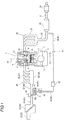
- Fig. 1 is a system configuration diagram of an intake and exhaust system of the engine 1
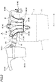
- Fig. 2 is a side view of the intake system 30
- Fig. 3 is an external perspective view of the intake system 30
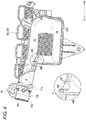
- Fig. 4 is a side view of an inner divided body 36a.
- Fig. 5 is a cross-sectional perspective view of an EGR passage 41
- Fig. 6 is an enlarged cross-sectional perspective view of a main section in which a main section in Fig. 5 is enlarged
- Fig. 7 is a front view of a projected section 465
- Fig. 8 is a plan view of the projected section 465.
- an arrow Fr and an arrow Rr indicate a longitudinal direction of the engine 1
- the arrow Fr indicates the front
- the arrow Rr indicates the rear
- an arrow Rh and an arrow Lh indicate a width direction of the engine 1
- the arrow Rh indicates a right direction
- the arrow Lh indicates a left direction.
- the engine 1 is illustrated by two-dot chain lines in Fig. 2
- a throttle body 35 is illustrated by two-dot chain lines in Fig. 7 .
- the engine 1 is particularly a so-called in-line four-cylinder engine in which one or more, particularly four cylinders are disposed in series along an axial center of a crankshaft 2.
- the engine 1 is particularly mounted in a vehicle or an automobile.
- this engine 1 is configured to include: an engine block 3 that supports the crankshaft 2 in a freely rotatable manner; a cylinder head 4; a head cover (not illustrated); and an oil pan 5.
- the cylinder head 4 is attached to an upper surface of the engine block 3, and the head cover is attached to an upper surface of the cylinder head 4. Furthermore, the oil pan 5 is attached to a lower surface of the engine block 3.
- each of cylinders 7 and combustion chambers 8 are formed along the longitudinal direction.
- Each of the cylinders 7 accommodates a piston 6 in a vertically slidable manner
- each of the combustion chambers 8 is a space including the cylinder 7, the piston 6, and the cylinder head 4.
- the cylinder head 4 of the engine 1 is formed with, for each of the cylinders 7: two intake ports 9, each of which communicates between the combustion chamber 8 and the outside of the engine 1; and two exhaust ports 10.
- the engine 1 includes, for each of the cylinders 7: intake valves 11 that open/close the intake ports 9; exhaust valves 12 that open/close the exhaust ports 10; a fuel injection injector 13 that injects the fuel into the combustion chamber 8; and an ignition plug 14 that ignites the fuel in the combustion chamber 8.
- an exhaust system 20 connected to the exhaust ports 10 and the intake system 30 connected to the intake ports 9 are arranged to oppose each other in the width direction with the engine 1 (particularly the cylinder head 4) being interposed therebetween.
- the exhaust system 20 is disposed on a right side of the engine 1. As illustrated in Fig. 1 , this exhaust system 20 is particularly configured to include: an exhaust manifold 21 that is connected to each of the exhaust ports 10 of the engine 1; and a first catalyst 23, a second catalyst 24, and a silencer (not illustrated), each of which is connected to the exhaust manifold 21 via an exhaust pipe 22.
- the first catalyst 23 is a three-way catalyst, for example.
- the second catalyst 24 is a gasoline particulate filter, for example.
- the intake system 30 is particularly configured to include an upstream intake passage 31, the throttle body 35, and a downstream intake passage 36 that are arranged on a left side of the engine 1.
- the intake system 30 further includes an exhaust gas recirculation system 40 (hereinafter referred to as an EGR system 40) that circulates some of exhaust gas into the downstream intake passage 36.
- EGR system 40 exhaust gas recirculation system 40
- the upstream intake passage 31, the throttle body 35, and the downstream intake passage 36 are connected in this order from the front to the rear, and the EGR system 40 is connected to the downstream intake passage 36.
- the upstream intake passage 31 is a passage having an internal space in which outside air is suctioned as the fresh air and flows into the throttle body 35. As illustrated in Fig. 1 and Fig. 2 , this upstream intake passage 31 is configured that a first air duct 32, an air cleaner 33, and a second air duct 34 are connected in this order from the front to the rear.
- the first air duct 32 is formed as a cylindrical body having an internal space through which the fresh air flows down.
- the air cleaner 33 has a function of removing dust contained in the fresh air that is suctioned via the first air duct 32.
- the second air duct 34 is a cylindrical body having an internal space through which the fresh air flows down, a front end thereof is connected to the air cleaner 33, and a rear end thereof is connected to the throttle body 35.
- the throttle body 35 has a function of adjusting or regulating a flow rate of the fresh air that flows down from the upstream intake passage 31 to the downstream intake passage 36.
- the throttle body 35 particularly includes: a hollow case 35a that communicates with the upstream intake passage 31 and the downstream intake passage 36; a throttle valve 35b that can freely open/close an internal space of the case 35a; and a valve shaft 35c that supports the throttle valve 35b (see Fig. 4 ).
- the downstream intake passage 36 is a branch pipe, a so-called intake manifold, through which the gas at least containing the fresh air is introduced into the intake ports 9 of the engine 1.
- the downstream intake passage 36 is integrally formed with a surge tank 38 that stabilizes a flow velocity of the gas at least containing the fresh air.
- this downstream intake passage 36 is configured by joining the inner divided body 36a, an intermediate divided body 36b, and an outer divided body 36c, each of which is made of a synthetic resin having heat resistance such as an engineering plastic, for example.
- these inner divided body 36a, intermediate divided body 36b, and outer divided body 36c are formed in such a shape of dividing the downstream intake passage 36.
- the downstream intake passage 36 defines an internal space that communicates between the internal space of the throttle body 35 and the intake ports 9 of the engine 1.
- a channel component 36d that constitutes an EGR passage 41 (a third EGR passage 46 and the projected section 465, which will be described later) is held between the inner divided body 36a and the intermediate divided body 36b.
- the internal space of the downstream intake passage 36 which communicates between the internal space of the throttle body 35 and the intake ports 9 of the engine 1, is defined by a fresh air introduction passage 37, the surge tank 38, and four independent intake pipes 39.
- the fresh air introduction passage 37, the surge tank 38, and the independent intake pipes 39 are disposed in this order from the throttle body 35 to the engine 1.
- the fresh air introduction passage 37, the surge tank 38, and the independent intake pipes 39 are disposed in this order from an upstream side to a downstream side of a flow of the gas at least containing the fresh air.
- a passage extending in the longitudinal direction is constructed of the inner divided body 36a and the intermediate divided body 36b, which are joined to each other in the width direction, at a position below the intake ports 9 of the engine 1 in a manner to have a longitudinal length reaching a rear portion of the engine 1.
- the fresh air introduction passage 37 is fastened to the throttle body 35 via a flange section 37a that is provided at a front end thereof.
- a space extends forward from a rear end of the fresh air introduction passage 37 that is curved downward, and is defined by the inner divided body 36a and the intermediate divided body 36b that are joined to each other in the width direction.
- each of the four independent intake pipes 39 is a passage that independently couples the surge tank 38 and the intake port 9 of the engine 1.
- Each of these independent intake pipes 39 is formed in a shape that is curved upward to the left in the width direction from a lower portion of the surge tank 38 in a manner to cross the fresh air introduction passage 37 and in which a tip thereof is located above the fresh air introduction passage 37.
- a portion of the independent intake pipe 39 that is curved upward to the left in the width direction from the lower portion of the surge tank 38 is constructed of the intermediate divided body 36b and the outer divided body 36c, and a portion thereof located above the fresh air introduction passage 37 is constructed of the inner divided body 36a, the intermediate divided body 36b, and the outer divided body 36c.
- the independent intake pipe 39 is formed in the curved shape that passes a position separated from the fresh air introduction passage 37 by a specified clearance on the left side in the width direction.
- two sound insulators S are disposed in the intermediate divided body 36b that constitutes a portion between the fresh air introduction passage 37 and the independent intake pipes 39.
- the two sound insulators S are disposed above and below a third exhaust gas introduction passage 463 and a fourth exhaust gas introduction passage 464 of the third EGR passage 46 while holding the third exhaust gas introduction passage 463 and the fourth exhaust gas introduction passage 464 therebetween.
- the EGR system 40 is particularly configured to include the EGR passage 41, an EGR cooler 42, and an EGR valve 43.
- the EGR passage 41 connects the exhaust system 20 and the downstream intake passage 36 so as to circulate some of the exhaust gas flowing toward the first catalyst 23 into the fresh air introduction passage 37.
- the EGR cooler 42 is a cooler of a water-cooling type, for example, and cools the exhaust gas to be circulated into the downstream intake passage 36. As illustrated in Fig. 2 , this EGR cooler 42 disposed near the rear portion of the engine 1.
- the EGR valve 43 is particularly an on-off valve that adjusts or regulates a flow rate of the exhaust gas to be circulated into the downstream intake passage 36. As illustrated in Fig. 2 and Fig. 3 , this EGR valve 43 is fastened and fixed to a portion of the downstream intake passage 36 between the second independent intake pipe 39 and the third independent intake pipe 39 from a front side of the engine 1.
- the EGR passage 41 is particularly configured to include: a first EGR passage 44 that connects the exhaust system 20 and the EGR cooler 42; a second EGR passage 45 that connects the EGR cooler 42 and the EGR valve 43; and the third EGR passage 46 that connects the EGR valve 43 and the fresh air introduction passage 37.
- the third EGR passage 46 is constructed of the space provided in the downstream intake passage 36.
- the third EGR passage 46 is configured to include a first exhaust gas introduction passage 461, a second exhaust gas introduction passage 462, the third exhaust gas introduction passage 463, the fourth exhaust gas introduction passage 464, and the projected section 465 that is projected to an internal space of the fresh air introduction passage 37.
- the first exhaust gas introduction passage 461 is constructed of a cylindrical body that is integrally formed with the outer divided body 36c. This first exhaust gas introduction passage 461 is formed in a shape that extends substantially downward and to the right in the width direction from the EGR valve 43.
- the second exhaust gas introduction passage 462 is constructed of the outer divided body 36c and the intermediate divided body 36b. This second exhaust gas introduction passage 462 is formed in a shape that extends substantially downward along the independent intake pipe 39 from the first exhaust gas introduction passage 461.
- the third exhaust gas introduction passage 463 is constructed of a cylindrical body that is integrally formed with the intermediate divided body 36b. This third exhaust gas introduction passage 463 is formed in a shape that extends to the right in the width direction from the second exhaust gas introduction passage 462.
- the fourth exhaust gas introduction passage 464 is constructed of the channel component 36d and the intermediate divided body 36b. This fourth exhaust gas introduction passage 464 is formed in a shape that extends forward along the fresh air introduction passage 37 from the third exhaust gas introduction passage 463.
- the third exhaust gas introduction passage 463 and the fourth exhaust gas introduction passage 464 which have been described above, are covered with the two sound insulators S provided between the fresh air introduction passage 37 and the independent intake pipes 39.
- the projected section 465 is configured to communicate with the fourth exhaust gas introduction passage 464 by the inner divided body 36a and the channel component 36d. As illustrated in Fig. 7 , when seen in a downflow direction that is a flow direction of the fresh air from the throttle valve 35b toward the fresh air introduction passage 37, this projected section 465 is formed to have a projected shape in a direction that crosses an axial direction of the valve shaft 35c.
- the projected section 465 is formed in a substantially cylindrical shape that is projected from an inner surface of the fresh air introduction passage 37.
- the projected section 465 is formed at a position on a downstream side of a negative-pressure region N (an area surrounded by a two-dot chain line in Fig. 4 ) that is generated adjacent to a downstream side of the throttle valve 35b and has a relatively negative pressure due to the flow of the fresh air that has flowed through the throttle valve 35b.
- the projected section 465 is formed in a substantially cylindrical shape in which a projection length as a height along a projected direction from the inner surface of the fresh air introduction passage 37 is gradually reduced from the upstream side to the downstream side.
- the projected section 465 is formed in the substantially cylindrical shape in which a projection length H1 on an outer circumferential surface on the upstream side is longer than a projection length H2 on the outer circumferential surface on the downstream side.
- this projected section 465 is formed such that, when the projection length H1 is set to be about a half of a rotation radius of the throttle valve 35b, a tip of the projected section 465 does not overlap the valve shaft 35c when seen from the downflow direction.
- the intake system 30 of the engine 1 which supplies the gas at least containing the fresh air to each of the cylinders 7 in the engine 1, includes: the throttle valve 35b that regulates an intake amount of the fresh air; and the downstream intake passage 36 having the internal space in which the fresh air having flowed through the throttle valve 35b is introduced into the cylinders of the engine 1.
- the intake system 30 of the engine 1 further includes the EGR passage 41 that communicates with the internal space of the downstream intake passage 36 and introduces some of the exhaust gas as the EGR gas into the downstream intake passage 36.
- the EGR passage 41 includes the projected section 465 in the substantially polygonal or cylindrical shape that is projected to the internal space of the downstream intake passage 36.
- the projected section 465 is formed to have the shape in which the projection length H1 on the outer circumferential surface on the upstream side is longer than the projection length H2 on the outer circumferential surface on the downstream side.
- the intake system 30 of the engine 1 can inhibit a flux of the EGR gas toward the throttle valve 35b by controlling the flux of the EGR gas in the internal space of the downstream intake passage 36.
- the projected section 465 of the EGR passage 41 is formed in the substantially polygonal or cylindrical shape in which the projection length H1 on the outer circumferential surface on the upstream side is longer than the projection length on a downstream lateral surface. Accordingly, in the projected section 465 of the EGR passage 41, the upstream lateral surface can function as a protective wall against the negative-pressure region N that is generated adjacent to the throttle valve 35b.
- the intake system 30 of the engine 1 can inhibit the EGR gas from being attracted to the negative-pressure region N.
- the intake system 30 of the engine 1 can introduce the EGR gas into the downstream intake passage 36 in a manner to flow along the flow of the fresh air that flows down toward the downstream portion of the downstream intake passage 36.
- the intake system 30 of the engine 1 can inhibit the flux of the EGR gas toward the throttle valve 35b by controlling the flux of the EGR gas in the internal space of the downstream intake passage 36. Furthermore, the projected section 465 of the EGR passage 41 can be provided in the further upstream portion of the downstream intake passage 36. Therefore, compared to a case where the projected section 465 of the EGR passage 41 is provided in the downstream portion of the downstream intake passage 36, the intake system 30 of the engine 1 can further reliably mix the fresh air and the EGR gas.
- the intake system 30 of the engine 1 can cause the fresh air to smoothly flow down along the circumferential surface of the projected section 465.
- the intake system 30 of the engine 1 can suppress intake resistance of the fresh air.
- the intake system 30 of the engine 1 can reliably deliver the EGR gas from the projected section 465 toward the downstream side of the downstream intake passage 36.
- the intake system 30 of the engine 1 can further inhibit the flux of the EGR gas toward the throttle valve 35b and can reliably cause the EGR gas, which is introduced into the downstream intake passage 36, to flow down to the downstream portion of the downstream intake passage 36.
- the projected section 465 of the EGR passage 41 is formed to be projected in the direction that crosses a valve shaft direction and to have the projection length that does not overlap the valve shaft 35c.
- the intake system 30 of the engine 1 in the downflow view, in the intake system 30 of the engine 1, it is possible to suppress a ratio of an area of the projected section 465 to an opening area of the downstream intake passage 36 to be low. Therefore, the intake system 30 of the engine 1 can further suppress the intake resistance of the fresh air.
- the projection length of the projected section 465 can be suppressed in comparison with the projected section 465 having a projection length that overlaps the valve shaft 35c in the downflow view.
- the tip of the projected section 465 can be positioned near the circumferential surface of the downstream intake passage 36 where the flow velocity of the fresh air is relatively high.
- the intake system 30 of the engine 1 can reliably merge the EGR gas with the flow of the fresh air toward the downstream portion of the downstream intake passage 36 at the relatively high flow velocity.
- the intake system 30 of the engine 1 can further reliably cause the EGR gas, which is introduced into the downstream intake passage 36, to flow down to the downstream portion of the downstream intake passage 36.
- the sound insulators S each of which covers the EGR passage 41, are provided, the heat in the EGR passage 41 can be retained in the intake system 30 of the engine 1.
- the EGR gas a temperature of which is suppressed from being reduced, toward the downstream portion of the downstream intake passage 36.
- the intake system 30 of the engine 1 can further suppress condensation of moisture contained in the EGR gas in the downstream intake passage 36. Therefore, the intake system 30 of the engine 1 can further reliably introduce the EGR gas containing the moisture into the cylinders of the engine 1.
- the intake passage in the present invention corresponds to the downstream intake passage 36 in the embodiment
- the projection length on the upstream lateral surface corresponds to the projection length H1 on the outer circumferential surface on the upstream side
- the projection length on the downstream lateral surface corresponds to the projection length H2 on the outer circumferential surface on the downstream side
- the porous member corresponds to the sound insulator S
- the present invention is not only limited to the configuration in the above-described embodiment but can be implemented in various embodiments.
- the engine 1 is the in-line four-cylinder engine.
- the engine 1 is not limited thereto, and may be an in-line six-cylinder engine, a V-type multicylinder engine, a single-cylinder engine, or the like.
- the engine 1 may be longitudinally mounted or horizontally mounted in a vehicle or an automobile.
- the downstream intake passage 36 is made of the synthetic resin. However, the downstream intake passage 36 is not limited thereto and may be a downstream intake passage that is made of metal.
- the downstream intake passage 36 includes the surge tank 38.
- the downstream intake passage 36 is not limited thereto and may be a downstream intake passage that does not include the surge tank 38.
- the third EGR passage 46 is constructed of the space provided in the downstream intake passage 36.
- the third EGR passage 46 is not limited thereto and may be a third EGR passage that is constructed of a different pipe from the downstream intake passage 36.
- the projected section may be constructed of the tip of the third EGR passage that is inserted in the fresh air introduction passage 37 of the downstream intake passage 36.
- it may be configured to insert the third EGR passage, which constructed of a different body, in the projected section integrally formed with the fresh air introduction passage 37.
- the projected section 465 has the substantially cylindrical shape.
- the projected section 465 is not limited thereto, and may be a projected section in a polygonal cylindrical shape, for example, as long as the projection length H1 on the upstream lateral surface is longer than the projection length H2 on the downstream lateral surface.
- the third exhaust gas introduction passage 463 and the fourth exhaust gas introduction passage 464 of the EGR passage 41 are configured to be covered with the sound insulators S.
- the third exhaust gas introduction passage 463 and the fourth exhaust gas introduction passage 464 may be covered with a sound absorbing material or a thermal insulator as long as the sound absorbing material or the thermal insulator is the porous member having the heat retaining property.
Landscapes
- Engineering & Computer Science (AREA)
- Chemical & Material Sciences (AREA)
- Combustion & Propulsion (AREA)
- Mechanical Engineering (AREA)
- General Engineering & Computer Science (AREA)
- Manufacturing & Machinery (AREA)
- Exhaust-Gas Circulating Devices (AREA)
Abstract
Description
- The present invention relates to an engine intake system including an exhaust gas recirculation system that introduces some of exhaust gas into an intake passage, through which fresh air flows down, for example. The present invention also relates to an engine.
- Conventionally, there are vehicles such as automobiles including an exhaust gas recirculation (EGR) system that introduces some of exhaust gas into an intake passage, through which fresh air flows down, in order to reduce nitrogen oxides in the exhaust gas and improve fuel economy.
- It has been known that, in an engine intake system that includes such an exhaust gas recirculation system, moisture contained in exhaust gas recirculation gas (hereinafter referred to as "EGR gas") is condensed in the intake passage at a relatively low temperature. For example, when an engine is stopped under environment below freezing point, this dew condensation water is frozen in the intake passage and possibly becomes a cause of unintended defect.
- In view of the above, various techniques of suppressing freezing of the moisture contained in the EGR gas have been proposed.
- For example, in
Patent document 1, an EGR passage (an EGR gas introduction channel) through which the EGR gas is introduced is provided along a wall surface of the intake passage (an intake manifold). In this way, inPatent document 1, the intake passage can be warmed. Thus, even in the case where the moisture contained in the EGR gas is condensed, the dew condensation water can flow down to a downstream portion of the intake passage before being frozen. - By the way, in
Patent document 1, the EGR passage is projected to an internal space of the intake passage, and a collision wall with which the EGR gas collides is provided at a tip of the EGR passage. As a result, inPatent document 1, the EGR gas is diffused in the intake passage to promote mixture of the fresh air and the EGR gas. - However, in the internal space on an uppermost stream side of the intake passage, a negative-pressure region having a relatively negative pressure is generated adjacent to a downstream side of a throttle valve by a flow of the fresh air that has flowed through the throttle valve. Thus, in
Patent document 1, the EGR gas, which has been diffused by the collision wall of the EGR passage, partially flows toward the throttle valve as being attracted to the negative-pressure region. - Then, in the case where some of the EGR gas is accumulated in the negative-pressure region near the throttle valve and the engine is stopped below freezing point, there is a possibility that the moisture contained in the EGR gas is condensed and attached to the throttle valve, and the attached dew condensation water is further frozen to possibly inhibit operation of the throttle valve.
- [Patent document 1]
JP-A-2017-31964 - In view of the above-described problem, the present invention has a purpose of inhibiting a flux of EGR gas toward a throttle valve by controlling the flux of the EGR gas in an internal space of an intake passage.
- The present invention is an engine intake system that supplies gas at least containing fresh air to each cylinder of an engine, and includes: a throttle valve that adjusts or regulates an intake amount of the fresh air; an intake passage having an internal space in which the fresh air having flowed through the throttle valve is introduced into the cylinder of the engine; and an EGR passage that communicates with the internal space of the intake passage and introduces some of exhaust gas as EGR gas into the intake passage. In particular, the EGR passage is configured to introduce a part of the exhaust gas as EGR gas into the intake passage. The EGR passage includes a projected section in a substantially polygonal or cylindrical shape that is projected to the internal space of the intake passage. Particularly, the projected section is formed in such a shape that a projection length on an upstream lateral surface is longer than a projection length on a downstream lateral surface. In other words, the projected section is particularly formed to have at least a first portion and a second portion which is downstream from the first portion in a flow direction of the fresh air in the intake passage. A projection length of the first portion is longer than a projection length of the second portion.
- According to the present invention, it is possible to inhibit a flux of the EGR gas toward the throttle valve by controlling the flux of the EGR gas in the internal space of the intake passage.
- More specifically, the projected section of the EGR passage is formed in the substantially polygonal or cylindrical shape in which the projection length on the upstream lateral surface is longer than the projection length on the downstream lateral surface. Accordingly, in the projected section of the EGR passage, the upstream lateral surface can function as a protective wall against a negative-pressure region that is generated adjacent to the throttle valve.
- As a result, even in the case where the projected section of the EGR passage is provided at a position near the throttle valve, the engine intake system can inhibit the EGR gas from being attracted to the negative-pressure region. Thus, the engine intake system can introduce the EGR gas into the intake passage in a manner to flow along a flow of the fresh air that flows down toward a downstream portion of the intake passage.
- Therefore, the engine intake system can inhibit the flux of the EGR gas toward the throttle valve by controlling the flux of the EGR gas in the internal space of the intake passage. Furthermore, the projected section of the EGR passage can be provided in a further upstream portion of the intake passage. Therefore, compared to a case where the projected section of the EGR passage is provided in the downstream portion of the intake passage, the engine intake system can further reliably mix the fresh air and the EGR gas.
- As an aspect of the present invention, the projected section of the EGR passage may be formed in the substantially cylindrical shape.
- According to this configuration, the engine intake system can cause the fresh air to smoothly flow down along a circumferential surface of the projected section. Thus, compared to a projected section in a substantially rectangular shape, for example, the engine intake system can suppress intake resistance of the fresh air.
- Furthermore, since the negative-pressure region is generated on a downstream side of the projected section by a flow of the fresh air, the engine intake system can reliably deliver the EGR gas from the projected section toward the downstream portion of the intake passage.
- Therefore, the engine intake system can further inhibit the flux of the EGR gas toward the throttle valve and can reliably cause the EGR gas, which is introduced into the intake passage, to flow down to the downstream portion of the intake passage.
- As an aspect of the present invention, a direction along a valve shaft of the throttle valve may be set as a valve shaft direction. Particularly, the projected section of the EGR passage may be formed to be projected in a direction that crosses the valve shaft direction. Further particularly, the projected section is formed to have the projection length that does not overlap the valve shaft at the time when the downstream portion of the intake passage is seen from the throttle valve.
- According to this configuration, in the engine intake system, it is possible to suppress a ratio of an area of the projected section to an opening area of the intake passage to be low when the downstream portion of the intake passage is seen from the throttle valve. Thus, the engine intake system can further suppress the intake resistance of the fresh air.
- Furthermore, when the downstream portion of the intake passage is seen from the throttle valve, the projection length of the projected section can be suppressed in comparison with a projected section having a projection length that overlaps the valve shaft. Thus, in the engine intake system, a tip of the projected section can be positioned near a circumferential surface of the intake passage where a flow velocity of the fresh air is relatively high.
- Therefore, the engine intake system can reliably merge the EGR gas with the flow of the fresh air that flows toward the downstream portion of the intake passage at the relatively high flow velocity.
- In this way, the engine intake system can further reliably cause the EGR gas, which is introduced into the intake passage, to flow down to the downstream portion of the intake passage.
- As an aspect of the present invention, a porous member that covers at least partially the EGR passage may be provided.
- The porous member means a sound absorbing material, a sound insulator, or a thermal insulator, for example.
- According to this configuration, the engine intake system can retain heat in the EGR passage. Thus, it is possible to introduce the EGR gas, a temperature of which is suppressed from being reduced, toward the downstream portion of the intake passage.
- In this way, the engine intake system can further suppress condensation of moisture contained in the EGR gas in the intake passage. Therefore, the engine intake system can further reliably introduce the EGR gas containing the moisture into the cylinder of the engine.
- Particularly, the engine intake system further includes an upstream intake passage. The throttle valve is provided between the intake passage and the upstream intake passage.
- Further particularly, the throttle valve is configured to adjust or regulate a flow rate of the fresh air from the upstream intake passage to the intake passage.
- Further particularly, the intake passage includes a surge tank.
- Further particularly, the intake passage is integrally formed with the surge tank.
- Further particularly, the EGR passage is at least partially formed integrally with the intake passage.
- Further particularly, the EGR passage is at least partially formed in an outer body of the intake passage.
- Further particularly, a projection length of the projected section is configured to continuously reduce in the flow direction of the fresh air.
- Further particularly, a projection length of the projected section is less than a rotation radius of the throttle valve.
- Further particularly, the projection length of the projected section is equal to, or substantially equal to a half of the rotation radius of the throttle valve.
- Further particularly, an engine includes the above engine intake system.
- Further particularly, an engine system includes an engine and the above engine intake system.
- The present invention can provide the engine intake system capable of inhibiting the flux of the EGR gas toward the throttle valve by controlling the flux of the EGR gas in the internal space of the intake passage.
-
- [
Fig. 1] Fig. 1 is a system configuration diagram illustrating a configuration of an intake and exhaust system of an engine. - [
Fig. 2] Fig. 2 is a side view illustrating external appearance of an intake system in a side view. - [
Fig. 3] Fig. 3 is an external perspective view in which the external appearance of the intake system is seen from above and the front. - [
Fig. 4] Fig. 4 is a side view illustrating external appearance of an inner divided body in a side view. - [
Fig. 5] Fig. 5 is a cross-sectional perspective view illustrating a partial cross section of an EGR passage. - [
Fig. 6] Fig. 6 is an enlarged cross-sectional perspective view of a main section in which a main section inFig. 5 is enlarged. - [
Fig. 7] Fig. 7 is a front view illustrating external appearance of a projected section in a front view. - [
Fig. 8] Fig. 8 is a plan view illustrating the external appearance of the projected section in a plan view. - A description will hereinafter be made on an embodiment of the present invention with reference to the drawings.
- In this embodiment, a description will be made on an
intake system 30 that supplies gas at least containing fresh air to anengine 1 using gasoline or the like as fuel with reference toFig. 1 to Fig. 8 . -
Fig. 1 is a system configuration diagram of an intake and exhaust system of theengine 1,Fig. 2 is a side view of theintake system 30,Fig. 3 is an external perspective view of theintake system 30, andFig. 4 is a side view of an inner dividedbody 36a. - Furthermore,
Fig. 5 is a cross-sectional perspective view of anEGR passage 41,Fig. 6 is an enlarged cross-sectional perspective view of a main section in which a main section inFig. 5 is enlarged,Fig. 7 is a front view of a projectedsection 465, andFig. 8 is a plan view of the projectedsection 465. - In the drawings, an arrow Fr and an arrow Rr indicate a longitudinal direction of the
engine 1, the arrow Fr indicates the front, and the arrow Rr indicates the rear. Furthermore, an arrow Rh and an arrow Lh indicate a width direction of theengine 1, the arrow Rh indicates a right direction, and the arrow Lh indicates a left direction. - In order to clarify the illustration, the
engine 1 is illustrated by two-dot chain lines inFig. 2 , and athrottle body 35 is illustrated by two-dot chain lines inFig. 7 . - First, the
engine 1 is particularly a so-called in-line four-cylinder engine in which one or more, particularly four cylinders are disposed in series along an axial center of acrankshaft 2. Theengine 1 is particularly mounted in a vehicle or an automobile. As illustrated inFig. 1 , thisengine 1 is configured to include: anengine block 3 that supports thecrankshaft 2 in a freely rotatable manner; a cylinder head 4; a head cover (not illustrated); and anoil pan 5. - The cylinder head 4 is attached to an upper surface of the
engine block 3, and the head cover is attached to an upper surface of the cylinder head 4. Furthermore, theoil pan 5 is attached to a lower surface of theengine block 3. - As illustrated in
Fig. 1 , in thisengine 1, four each of cylinders 7 andcombustion chambers 8 are formed along the longitudinal direction. Each of the cylinders 7 accommodates a piston 6 in a vertically slidable manner, and each of thecombustion chambers 8 is a space including the cylinder 7, the piston 6, and the cylinder head 4. - Furthermore, as illustrated in
Fig. 1 , the cylinder head 4 of theengine 1 is formed with, for each of the cylinders 7: twointake ports 9, each of which communicates between thecombustion chamber 8 and the outside of theengine 1; and twoexhaust ports 10. - In addition, as illustrated in
Fig. 1 , theengine 1 includes, for each of the cylinders 7:intake valves 11 that open/close theintake ports 9;exhaust valves 12 that open/close theexhaust ports 10; afuel injection injector 13 that injects the fuel into thecombustion chamber 8; and anignition plug 14 that ignites the fuel in thecombustion chamber 8. - Here, a description will be made by setting a direction along the axial center of the
crankshaft 2 in theengine 1 as the longitudinal direction of theengine 1 and setting a horizontal direction that is substantially orthogonal to the longitudinal direction in the front view as the width direction of theengine 1. - As illustrated in
Fig. 1 , in this engine 1 (or an engine system), anexhaust system 20 connected to theexhaust ports 10 and theintake system 30 connected to theintake ports 9 are arranged to oppose each other in the width direction with the engine 1 (particularly the cylinder head 4) being interposed therebetween. - The
exhaust system 20 is disposed on a right side of theengine 1. As illustrated inFig. 1 , thisexhaust system 20 is particularly configured to include: anexhaust manifold 21 that is connected to each of theexhaust ports 10 of theengine 1; and afirst catalyst 23, asecond catalyst 24, and a silencer (not illustrated), each of which is connected to theexhaust manifold 21 via anexhaust pipe 22. - The
first catalyst 23 is a three-way catalyst, for example. Thesecond catalyst 24 is a gasoline particulate filter, for example. - Meanwhile, as illustrated in
Fig. 1 andFig. 2 , theintake system 30 is particularly configured to include anupstream intake passage 31, thethrottle body 35, and adownstream intake passage 36 that are arranged on a left side of theengine 1. Theintake system 30 further includes an exhaust gas recirculation system 40 (hereinafter referred to as an EGR system 40) that circulates some of exhaust gas into thedownstream intake passage 36. - The
upstream intake passage 31, thethrottle body 35, and thedownstream intake passage 36 are connected in this order from the front to the rear, and theEGR system 40 is connected to thedownstream intake passage 36. - The
upstream intake passage 31 is a passage having an internal space in which outside air is suctioned as the fresh air and flows into thethrottle body 35. As illustrated inFig. 1 andFig. 2 , thisupstream intake passage 31 is configured that afirst air duct 32, anair cleaner 33, and asecond air duct 34 are connected in this order from the front to the rear. - The
first air duct 32 is formed as a cylindrical body having an internal space through which the fresh air flows down. - The
air cleaner 33 has a function of removing dust contained in the fresh air that is suctioned via thefirst air duct 32. - The
second air duct 34 is a cylindrical body having an internal space through which the fresh air flows down, a front end thereof is connected to theair cleaner 33, and a rear end thereof is connected to thethrottle body 35. - As illustrated in
Fig. 1 andFig. 2 , thethrottle body 35 has a function of adjusting or regulating a flow rate of the fresh air that flows down from theupstream intake passage 31 to thedownstream intake passage 36. - More specifically, the
throttle body 35 particularly includes: ahollow case 35a that communicates with theupstream intake passage 31 and thedownstream intake passage 36; athrottle valve 35b that can freely open/close an internal space of thecase 35a; and avalve shaft 35c that supports thethrottle valve 35b (seeFig. 4 ). - The
downstream intake passage 36 is a branch pipe, a so-called intake manifold, through which the gas at least containing the fresh air is introduced into theintake ports 9 of theengine 1. Thedownstream intake passage 36 is integrally formed with asurge tank 38 that stabilizes a flow velocity of the gas at least containing the fresh air. - As illustrated in
Fig. 3 to Fig. 5 , thisdownstream intake passage 36 is configured by joining the inner dividedbody 36a, an intermediate dividedbody 36b, and an outer dividedbody 36c, each of which is made of a synthetic resin having heat resistance such as an engineering plastic, for example. In a substantially vertical cross section along the longitudinal direction, these inner dividedbody 36a, intermediate dividedbody 36b, and outer dividedbody 36c are formed in such a shape of dividing thedownstream intake passage 36. - By joining the inner divided
body 36a, the intermediate dividedbody 36b, and the outer dividedbody 36c in the width direction, thedownstream intake passage 36 defines an internal space that communicates between the internal space of thethrottle body 35 and theintake ports 9 of theengine 1. - As illustrated in
Fig. 5 , achannel component 36d that constitutes an EGR passage 41 (athird EGR passage 46 and the projectedsection 465, which will be described later) is held between the inner dividedbody 36a and the intermediate dividedbody 36b. - In detail, as illustrated in
Fig. 2 to Fig. 5 , the internal space of thedownstream intake passage 36, which communicates between the internal space of thethrottle body 35 and theintake ports 9 of theengine 1, is defined by a freshair introduction passage 37, thesurge tank 38, and fourindependent intake pipes 39. - The fresh
air introduction passage 37, thesurge tank 38, and theindependent intake pipes 39 are disposed in this order from thethrottle body 35 to theengine 1. In other words, the freshair introduction passage 37, thesurge tank 38, and theindependent intake pipes 39 are disposed in this order from an upstream side to a downstream side of a flow of the gas at least containing the fresh air. - As illustrated in
Fig. 2 to Fig. 5 , in regard to the freshair introduction passage 37, a passage extending in the longitudinal direction is constructed of the inner dividedbody 36a and the intermediate dividedbody 36b, which are joined to each other in the width direction, at a position below theintake ports 9 of theengine 1 in a manner to have a longitudinal length reaching a rear portion of theengine 1. As illustrated inFig. 3 andFig. 4 , the freshair introduction passage 37 is fastened to thethrottle body 35 via aflange section 37a that is provided at a front end thereof. - As illustrated in
Fig. 3 to Fig. 5 , in thesurge tank 38, a space extends forward from a rear end of the freshair introduction passage 37 that is curved downward, and is defined by the inner dividedbody 36a and the intermediate dividedbody 36b that are joined to each other in the width direction. - As illustrated in
Fig. 3 to Fig. 5 , each of the fourindependent intake pipes 39 is a passage that independently couples thesurge tank 38 and theintake port 9 of theengine 1. Each of theseindependent intake pipes 39 is formed in a shape that is curved upward to the left in the width direction from a lower portion of thesurge tank 38 in a manner to cross the freshair introduction passage 37 and in which a tip thereof is located above the freshair introduction passage 37. - More specifically, a portion of the
independent intake pipe 39 that is curved upward to the left in the width direction from the lower portion of thesurge tank 38 is constructed of the intermediate dividedbody 36b and the outer dividedbody 36c, and a portion thereof located above the freshair introduction passage 37 is constructed of the inner dividedbody 36a, the intermediate dividedbody 36b, and the outer dividedbody 36c. - The
independent intake pipe 39 is formed in the curved shape that passes a position separated from the freshair introduction passage 37 by a specified clearance on the left side in the width direction. As illustrated inFig. 5 , in the intermediate dividedbody 36b that constitutes a portion between the freshair introduction passage 37 and theindependent intake pipes 39, two sound insulators S, each of which is a porous member having a sound insulating property and a heat retaining property, are disposed. - More specifically, as illustrated in
Fig. 5 andFig. 6 , the two sound insulators S are disposed above and below a third exhaustgas introduction passage 463 and a fourth exhaustgas introduction passage 464 of thethird EGR passage 46 while holding the third exhaustgas introduction passage 463 and the fourth exhaustgas introduction passage 464 therebetween. - As illustrated in
Fig. 1 to Fig. 3 , theEGR system 40 is particularly configured to include theEGR passage 41, anEGR cooler 42, and anEGR valve 43. - The
EGR passage 41 connects theexhaust system 20 and thedownstream intake passage 36 so as to circulate some of the exhaust gas flowing toward thefirst catalyst 23 into the freshair introduction passage 37. - The
EGR cooler 42 is a cooler of a water-cooling type, for example, and cools the exhaust gas to be circulated into thedownstream intake passage 36. As illustrated inFig. 2 , this EGR cooler 42 disposed near the rear portion of theengine 1. - The
EGR valve 43 is particularly an on-off valve that adjusts or regulates a flow rate of the exhaust gas to be circulated into thedownstream intake passage 36. As illustrated inFig. 2 andFig. 3 , thisEGR valve 43 is fastened and fixed to a portion of thedownstream intake passage 36 between the secondindependent intake pipe 39 and the thirdindependent intake pipe 39 from a front side of theengine 1. - The description will continue on the
EGR passage 41 of the above-describedEGR system 40. - As illustrated in
Fig. 1 to Fig. 3 , theEGR passage 41 is particularly configured to include: afirst EGR passage 44 that connects theexhaust system 20 and theEGR cooler 42; asecond EGR passage 45 that connects theEGR cooler 42 and theEGR valve 43; and thethird EGR passage 46 that connects theEGR valve 43 and the freshair introduction passage 37. - Of these, as illustrated in
Fig. 5 andFig. 6 , thethird EGR passage 46 is constructed of the space provided in thedownstream intake passage 36. - More specifically, as illustrated in
Fig. 5 andFig. 6 , thethird EGR passage 46 is configured to include a first exhaustgas introduction passage 461, a second exhaustgas introduction passage 462, the third exhaustgas introduction passage 463, the fourth exhaustgas introduction passage 464, and the projectedsection 465 that is projected to an internal space of the freshair introduction passage 37. - As illustrated in
Fig. 6 , the first exhaustgas introduction passage 461 is constructed of a cylindrical body that is integrally formed with the outer dividedbody 36c. This first exhaustgas introduction passage 461 is formed in a shape that extends substantially downward and to the right in the width direction from theEGR valve 43. - As illustrated in
Fig. 6 , the second exhaustgas introduction passage 462 is constructed of the outer dividedbody 36c and the intermediate dividedbody 36b. This second exhaustgas introduction passage 462 is formed in a shape that extends substantially downward along theindependent intake pipe 39 from the first exhaustgas introduction passage 461. - As illustrated in
Fig. 6 , the third exhaustgas introduction passage 463 is constructed of a cylindrical body that is integrally formed with the intermediate dividedbody 36b. This third exhaustgas introduction passage 463 is formed in a shape that extends to the right in the width direction from the second exhaustgas introduction passage 462. - As illustrated in
Fig. 6 , the fourth exhaustgas introduction passage 464 is constructed of thechannel component 36d and the intermediate dividedbody 36b. This fourth exhaustgas introduction passage 464 is formed in a shape that extends forward along the freshair introduction passage 37 from the third exhaustgas introduction passage 463. - As illustrated in
Fig. 6 , the third exhaustgas introduction passage 463 and the fourth exhaustgas introduction passage 464, which have been described above, are covered with the two sound insulators S provided between the freshair introduction passage 37 and theindependent intake pipes 39. - As illustrated in
Fig. 4 andFig. 6 , the projectedsection 465 is configured to communicate with the fourth exhaustgas introduction passage 464 by the inner dividedbody 36a and thechannel component 36d. As illustrated inFig. 7 , when seen in a downflow direction that is a flow direction of the fresh air from thethrottle valve 35b toward the freshair introduction passage 37, this projectedsection 465 is formed to have a projected shape in a direction that crosses an axial direction of thevalve shaft 35c. - In detail, as illustrated in
Fig. 4 ,Fig. 6 , andFig. 8 , in a portion of the freshair introduction passage 37 on an upstream side of a substantially central portion in the downflow direction, the projectedsection 465 is formed in a substantially cylindrical shape that is projected from an inner surface of the freshair introduction passage 37. As illustrated inFig. 4 , the projectedsection 465 is formed at a position on a downstream side of a negative-pressure region N (an area surrounded by a two-dot chain line inFig. 4 ) that is generated adjacent to a downstream side of thethrottle valve 35b and has a relatively negative pressure due to the flow of the fresh air that has flowed through thethrottle valve 35b. - Furthermore, as illustrated in
Fig. 4 , the projectedsection 465 is formed in a substantially cylindrical shape in which a projection length as a height along a projected direction from the inner surface of the freshair introduction passage 37 is gradually reduced from the upstream side to the downstream side. - More specifically, as illustrated in
Fig. 4 , in the side view, the projectedsection 465 is formed in the substantially cylindrical shape in which a projection length H1 on an outer circumferential surface on the upstream side is longer than a projection length H2 on the outer circumferential surface on the downstream side. As illustrated inFig. 4 andFig. 8 , this projectedsection 465 is formed such that, when the projection length H1 is set to be about a half of a rotation radius of thethrottle valve 35b, a tip of the projectedsection 465 does not overlap thevalve shaft 35c when seen from the downflow direction. - As it has been described so far, the
intake system 30 of theengine 1, which supplies the gas at least containing the fresh air to each of the cylinders 7 in theengine 1, includes: thethrottle valve 35b that regulates an intake amount of the fresh air; and thedownstream intake passage 36 having the internal space in which the fresh air having flowed through thethrottle valve 35b is introduced into the cylinders of theengine 1. Theintake system 30 of theengine 1 further includes theEGR passage 41 that communicates with the internal space of thedownstream intake passage 36 and introduces some of the exhaust gas as the EGR gas into thedownstream intake passage 36. TheEGR passage 41 includes the projectedsection 465 in the substantially polygonal or cylindrical shape that is projected to the internal space of thedownstream intake passage 36. The projectedsection 465 is formed to have the shape in which the projection length H1 on the outer circumferential surface on the upstream side is longer than the projection length H2 on the outer circumferential surface on the downstream side. - In this way, the
intake system 30 of theengine 1 can inhibit a flux of the EGR gas toward thethrottle valve 35b by controlling the flux of the EGR gas in the internal space of thedownstream intake passage 36. - More specifically, the projected
section 465 of theEGR passage 41 is formed in the substantially polygonal or cylindrical shape in which the projection length H1 on the outer circumferential surface on the upstream side is longer than the projection length on a downstream lateral surface. Accordingly, in the projectedsection 465 of theEGR passage 41, the upstream lateral surface can function as a protective wall against the negative-pressure region N that is generated adjacent to thethrottle valve 35b. - As a result, even in the case where the projected
section 465 of theEGR passage 41 is provided at the position near thethrottle valve 35b, theintake system 30 of theengine 1 can inhibit the EGR gas from being attracted to the negative-pressure region N. Thus, theintake system 30 of theengine 1 can introduce the EGR gas into thedownstream intake passage 36 in a manner to flow along the flow of the fresh air that flows down toward the downstream portion of thedownstream intake passage 36. - Therefore, the
intake system 30 of theengine 1 can inhibit the flux of the EGR gas toward thethrottle valve 35b by controlling the flux of the EGR gas in the internal space of thedownstream intake passage 36. Furthermore, the projectedsection 465 of theEGR passage 41 can be provided in the further upstream portion of thedownstream intake passage 36. Therefore, compared to a case where the projectedsection 465 of theEGR passage 41 is provided in the downstream portion of thedownstream intake passage 36, theintake system 30 of theengine 1 can further reliably mix the fresh air and the EGR gas. - In addition, since the projected
section 465 of theEGR passage 41 is formed in the substantially cylindrical shape, theintake system 30 of theengine 1 can cause the fresh air to smoothly flow down along the circumferential surface of the projectedsection 465. Thus, compared to the projectedsection 465 in a substantially rectangular shape, for example, theintake system 30 of theengine 1 can suppress intake resistance of the fresh air. - Furthermore, since the negative-pressure region N is generated on the downstream side of the projected
section 465 by the flow of the fresh air, theintake system 30 of theengine 1 can reliably deliver the EGR gas from the projectedsection 465 toward the downstream side of thedownstream intake passage 36. - Therefore, the
intake system 30 of theengine 1 can further inhibit the flux of the EGR gas toward thethrottle valve 35b and can reliably cause the EGR gas, which is introduced into thedownstream intake passage 36, to flow down to the downstream portion of thedownstream intake passage 36. - In a downflow view that is seen in the downflow direction, the projected
section 465 of theEGR passage 41 is formed to be projected in the direction that crosses a valve shaft direction and to have the projection length that does not overlap thevalve shaft 35c. - As a result, in the downflow view, in the
intake system 30 of theengine 1, it is possible to suppress a ratio of an area of the projectedsection 465 to an opening area of thedownstream intake passage 36 to be low. Therefore, theintake system 30 of theengine 1 can further suppress the intake resistance of the fresh air. - Furthermore, the projection length of the projected
section 465 can be suppressed in comparison with the projectedsection 465 having a projection length that overlaps thevalve shaft 35c in the downflow view. Thus, in theintake system 30 of theengine 1, the tip of the projectedsection 465 can be positioned near the circumferential surface of thedownstream intake passage 36 where the flow velocity of the fresh air is relatively high. - As a result, the
intake system 30 of theengine 1 can reliably merge the EGR gas with the flow of the fresh air toward the downstream portion of thedownstream intake passage 36 at the relatively high flow velocity. - Therefore, the
intake system 30 of theengine 1 can further reliably cause the EGR gas, which is introduced into thedownstream intake passage 36, to flow down to the downstream portion of thedownstream intake passage 36. - Moreover, since the sound insulators S, each of which covers the
EGR passage 41, are provided, the heat in theEGR passage 41 can be retained in theintake system 30 of theengine 1. Thus, it is possible to introduce the EGR gas, a temperature of which is suppressed from being reduced, toward the downstream portion of thedownstream intake passage 36. - In this way, the
intake system 30 of theengine 1 can further suppress condensation of moisture contained in the EGR gas in thedownstream intake passage 36. Therefore, theintake system 30 of theengine 1 can further reliably introduce the EGR gas containing the moisture into the cylinders of theengine 1. - In correspondences between the configuration of the present invention and that of the above-described embodiment,
the intake passage in the present invention corresponds to thedownstream intake passage 36 in the embodiment,
similarly,
the projection length on the upstream lateral surface corresponds to the projection length H1 on the outer circumferential surface on the upstream side,
the projection length on the downstream lateral surface corresponds to the projection length H2 on the outer circumferential surface on the downstream side, and
the porous member corresponds to the sound insulator S, but the present invention is not only limited to the configuration in the above-described embodiment but can be implemented in various embodiments. - For example, in the above-described embodiment, the
engine 1 is the in-line four-cylinder engine. However, theengine 1 is not limited thereto, and may be an in-line six-cylinder engine, a V-type multicylinder engine, a single-cylinder engine, or the like. Theengine 1 may be longitudinally mounted or horizontally mounted in a vehicle or an automobile. - The
downstream intake passage 36 is made of the synthetic resin. However, thedownstream intake passage 36 is not limited thereto and may be a downstream intake passage that is made of metal. - The
downstream intake passage 36 includes thesurge tank 38. However, thedownstream intake passage 36 is not limited thereto and may be a downstream intake passage that does not include thesurge tank 38. - The
third EGR passage 46 is constructed of the space provided in thedownstream intake passage 36. However, thethird EGR passage 46 is not limited thereto and may be a third EGR passage that is constructed of a different pipe from thedownstream intake passage 36. - At this time, the projected section may be constructed of the tip of the third EGR passage that is inserted in the fresh
air introduction passage 37 of thedownstream intake passage 36. Alternatively, it may be configured to insert the third EGR passage, which constructed of a different body, in the projected section integrally formed with the freshair introduction passage 37. - The projected
section 465 has the substantially cylindrical shape. However, the projectedsection 465 is not limited thereto, and may be a projected section in a polygonal cylindrical shape, for example, as long as the projection length H1 on the upstream lateral surface is longer than the projection length H2 on the downstream lateral surface. - The third exhaust
gas introduction passage 463 and the fourth exhaustgas introduction passage 464 of theEGR passage 41 are configured to be covered with the sound insulators S. However, the third exhaustgas introduction passage 463 and the fourth exhaustgas introduction passage 464 may be covered with a sound absorbing material or a thermal insulator as long as the sound absorbing material or the thermal insulator is the porous member having the heat retaining property. -
- 1: Engine
- 7: Cylinder
- 30: Intake system
- 35b: Throttle valve
- 35c: Valve shaft
- 36: Downstream intake passage
- 41: EGR passage
- 465: Projected section
- H1: Projection length on outer circumferential surface on upstream side
- H2: Projection length on outer circumferential surface on downstream side
- S: Sound insulator
Claims (15)
- An engine intake system (30) configured to supply gas at least containing fresh air to each cylinder (7) of an engine (1), the engine intake system (30) comprising:a throttle valve (35b) configured to adjust or regulate an intake amount of the fresh air;an intake passage (36) having an internal space in which the fresh air having flowed through the throttle valve (35b) is introduced into the cylinder (7) of the engine (1); andan EGR passage (41) that communicates with the internal space of the intake passage (36) and configured to introduce some of exhaust gas as EGR gas into the intake passage (36), whereinthe EGR passage (41) includes a projected section (465) in a substantially polygonal or cylindrical shape that is configured to project to the internal space of the intake passage (36), andthe projected section (465) is formed in such a shape that a projection length (H1) on an upstream lateral surface is longer than a projection length (H2) on a downstream lateral surface.
- The engine intake system (30) according to claim 1, wherein
the projected section (465) of the EGR passage (41) is formed in the substantially cylindrical shape. - The engine intake system (30) according to claim 1 or 2, wherein
the projected section (465) of the EGR passage (41) is formed to be projected in a direction that crosses a direction along a valve shaft (35c) of the throttle valve (35b) . - The engine intake system (30) according to claim 3, wherein
the projected section (465) is formed to have a projection length that does not overlap the valve shaft (35c) at the time when a downstream portion of the intake passage (36) is seen from the throttle valve (35b). - The engine intake system (30) according to any one of the preceding claims, further comprising:
a porous member (S) configured to cover at least partially the EGR passage (41). - The engine intake system (30) according to any one of the preceding claims, further comprising an upstream intake passage (31), wherein
the throttle valve (35b) is provided between the intake passage (36) and the upstream intake passage (36). - The engine intake system (30) according to claim 6, wherein
the throttle valve (35b) is configured to adjust or regulate a flow rate of the fresh air from the upstream intake passage (31) to the intake passage (36). - The engine intake system (30) according to any one of the preceding claims, wherein
the intake passage (36) includes a surge tank (38). - The engine intake system (30) according to claim 8, wherein
the intake passage (36) is integrally formed with the surge tank (38). - The engine intake system (30) according to any one of the preceding claims, wherein
the EGR passage (41) is at least partially formed integrally with the intake passage (36). - The engine intake system (30) according to any one of the preceding claims, wherein
the EGR passage (41) is at least partially formed in an outer body (36c) of the intake passage (36). - The engine intake system (30) according to any one of the preceding claims, wherein
a projection length of the projected section (465) is configured to continuously reduce in the flow direction of the fresh air. - The engine intake system (30) according to any one of the preceding claims, wherein
a projection length of the projected section (465) is less than a rotation radius of the throttle valve (35b). - The engine intake system (30) according to claim 13, wherein
the projection length of the projected section (465) is equal to, or substantially equal to, a half of the rotation radius of the throttle valve (35b). - An engine (1) comprising the engine intake system (30) according to any one of the preceding claims.
Applications Claiming Priority (1)
| Application Number | Priority Date | Filing Date | Title |
|---|---|---|---|
| JP2019142057A JP7358824B2 (en) | 2019-08-01 | 2019-08-01 | engine intake system |
Publications (2)
| Publication Number | Publication Date |
|---|---|
| EP3771816A1 true EP3771816A1 (en) | 2021-02-03 |
| EP3771816B1 EP3771816B1 (en) | 2024-10-23 |
Family
ID=71741649
Family Applications (1)
| Application Number | Title | Priority Date | Filing Date |
|---|---|---|---|
| EP20187100.1A Active EP3771816B1 (en) | 2019-08-01 | 2020-07-22 | Engine intake system, and engine |
Country Status (4)
| Country | Link |
|---|---|
| US (1) | US11067042B2 (en) |
| EP (1) | EP3771816B1 (en) |
| JP (1) | JP7358824B2 (en) |
| CN (1) | CN112302836B (en) |
Families Citing this family (3)
| Publication number | Priority date | Publication date | Assignee | Title |
|---|---|---|---|---|
| JP7259788B2 (en) * | 2020-03-18 | 2023-04-18 | トヨタ自動車株式会社 | EGR device |
| JP7635637B2 (en) * | 2021-05-26 | 2025-02-26 | マツダ株式会社 | Intake manifold structure |
| CN114033586B (en) * | 2021-10-26 | 2022-09-27 | 东风汽车集团股份有限公司 | Throttle valve ice breaking method and device |
Citations (7)
| Publication number | Priority date | Publication date | Assignee | Title |
|---|---|---|---|---|
| JPH04103251U (en) * | 1991-01-25 | 1992-09-07 | アイシン精機株式会社 | Exhaust gas recirculation device |
| US5492104A (en) * | 1994-11-03 | 1996-02-20 | General Motors Corporation | Exhaust gas recirculation for an internal combustion engine |
| EP1522714A2 (en) * | 2003-10-10 | 2005-04-13 | Nissan Motor Company, Limited | Intake device for internal combustion engine |
| WO2006129371A1 (en) * | 2005-06-03 | 2006-12-07 | Hitachi, Ltd. | Egr gas mixer |
| EP2330278A1 (en) * | 2008-12-17 | 2011-06-08 | Aisin Seiki Kabushiki Kaisha | Air intake manifold |
| JP2017031964A (en) | 2015-08-06 | 2017-02-09 | マツダ株式会社 | Engine intake system |
| DE112016005387T5 (en) * | 2015-11-25 | 2018-08-09 | Aisin Seiki Kabushiki Kaisha | Air intake device for internal combustion engine |
Family Cites Families (9)
| Publication number | Priority date | Publication date | Assignee | Title |
|---|---|---|---|---|
| JPH04279754A (en) * | 1991-03-08 | 1992-10-05 | Toyota Autom Loom Works Ltd | Egr gas deposit reducing manifold |
| JPH06147022A (en) * | 1992-11-04 | 1994-05-27 | Mitsubishi Motors Corp | Cylinder injection type internal combustion engine |
| JP3528565B2 (en) * | 1998-01-20 | 2004-05-17 | 日産自動車株式会社 | Engine exhaust gas recirculation system |
| JP3674389B2 (en) | 1999-04-21 | 2005-07-20 | 日産自動車株式会社 | Intake manifold for internal combustion engine |
| JP2013011185A (en) * | 2011-06-28 | 2013-01-17 | Aisin Seiki Co Ltd | Air intake device for internal combustion engine |
| US20140150759A1 (en) * | 2012-12-04 | 2014-06-05 | GM Global Technology Operations LLC | Engine Including External EGR System |
| US10465637B2 (en) * | 2013-02-28 | 2019-11-05 | Bendix Commercial Vehicle Systems, Llc | Method to enhance gas recirculation in turbocharged diesel engines |
| US20150267650A1 (en) * | 2014-03-24 | 2015-09-24 | International Engine Intellectual Property Company, Llc | Venturi egr pump |
| JP2018105180A (en) | 2016-12-26 | 2018-07-05 | 愛三工業株式会社 | Intake manifold |
-
2019
- 2019-08-01 JP JP2019142057A patent/JP7358824B2/en active Active
-
2020
- 2020-07-15 CN CN202010678412.6A patent/CN112302836B/en active Active
- 2020-07-21 US US16/934,035 patent/US11067042B2/en active Active
- 2020-07-22 EP EP20187100.1A patent/EP3771816B1/en active Active
Patent Citations (7)
| Publication number | Priority date | Publication date | Assignee | Title |
|---|---|---|---|---|
| JPH04103251U (en) * | 1991-01-25 | 1992-09-07 | アイシン精機株式会社 | Exhaust gas recirculation device |
| US5492104A (en) * | 1994-11-03 | 1996-02-20 | General Motors Corporation | Exhaust gas recirculation for an internal combustion engine |
| EP1522714A2 (en) * | 2003-10-10 | 2005-04-13 | Nissan Motor Company, Limited | Intake device for internal combustion engine |
| WO2006129371A1 (en) * | 2005-06-03 | 2006-12-07 | Hitachi, Ltd. | Egr gas mixer |
| EP2330278A1 (en) * | 2008-12-17 | 2011-06-08 | Aisin Seiki Kabushiki Kaisha | Air intake manifold |
| JP2017031964A (en) | 2015-08-06 | 2017-02-09 | マツダ株式会社 | Engine intake system |
| DE112016005387T5 (en) * | 2015-11-25 | 2018-08-09 | Aisin Seiki Kabushiki Kaisha | Air intake device for internal combustion engine |
Also Published As
| Publication number | Publication date |
|---|---|
| JP2021025439A (en) | 2021-02-22 |
| EP3771816B1 (en) | 2024-10-23 |
| JP7358824B2 (en) | 2023-10-11 |
| US20210033050A1 (en) | 2021-02-04 |
| US11067042B2 (en) | 2021-07-20 |
| CN112302836A (en) | 2021-02-02 |
| CN112302836B (en) | 2022-11-08 |
Similar Documents
| Publication | Publication Date | Title |
|---|---|---|
| US9010304B2 (en) | Exhaust gas recirculation device of engine | |
| EP3771816B1 (en) | Engine intake system, and engine | |
| US10612499B2 (en) | Air intake apparatus | |
| US10731607B2 (en) | Air intake apparatus for internal combustion engine | |
| EP3290682B1 (en) | Intake device for internal combustion engines | |
| US10550804B2 (en) | Air intake apparatus of multi-cylinder engine having secondary gas inlet passage connected to intake air inlet passage | |
| JP6332192B2 (en) | Engine intake system | |
| US7328692B2 (en) | Intake device for internal combustion engine | |
| EP0842352A1 (en) | Stratified charge engine | |
| JP6098652B2 (en) | Multi-cylinder engine intake system | |
| JP6128142B2 (en) | Multi-cylinder engine intake system | |
| US6526933B2 (en) | Multi-cylinder internal combustion engine | |
| US20100037853A1 (en) | Intake system for an internal combustion engine | |
| US10196969B2 (en) | Exhaust device for engine | |
| JP7110584B2 (en) | engine intake mechanism | |
| US20230175464A1 (en) | Egr device | |
| US9810173B2 (en) | Engine assembly | |
| JPH06173782A (en) | EGR supply device for engine | |
| US10350987B2 (en) | Upper structure of vehicle engine | |
| JPH022934Y2 (en) | ||
| CN113494393A (en) | EGR system of engine | |
| JP7316515B2 (en) | engine exhaust circulation system | |
| JP7663077B2 (en) | Engine intake system structure | |
| US20050235941A1 (en) | Intake manifold having intake pipes linked by transverse acoustic synchronization channels with exhaust gas recirculation inlets | |
| JP7636732B2 (en) | Engine intake system structure |
Legal Events
| Date | Code | Title | Description |
|---|---|---|---|
| PUAI | Public reference made under article 153(3) epc to a published international application that has entered the european phase |
Free format text: ORIGINAL CODE: 0009012 |
|
| STAA | Information on the status of an ep patent application or granted ep patent |
Free format text: STATUS: THE APPLICATION HAS BEEN PUBLISHED |
|
| AK | Designated contracting states |
Kind code of ref document: A1 Designated state(s): AL AT BE BG CH CY CZ DE DK EE ES FI FR GB GR HR HU IE IS IT LI LT LU LV MC MK MT NL NO PL PT RO RS SE SI SK SM TR |
|
| AX | Request for extension of the european patent |
Extension state: BA ME |
|
| STAA | Information on the status of an ep patent application or granted ep patent |
Free format text: STATUS: REQUEST FOR EXAMINATION WAS MADE |
|
| 17P | Request for examination filed |
Effective date: 20210624 |
|
| RBV | Designated contracting states (corrected) |
Designated state(s): AL AT BE BG CH CY CZ DE DK EE ES FI FR GB GR HR HU IE IS IT LI LT LU LV MC MK MT NL NO PL PT RO RS SE SI SK SM TR |
|
| STAA | Information on the status of an ep patent application or granted ep patent |
Free format text: STATUS: EXAMINATION IS IN PROGRESS |
|
| 17Q | First examination report despatched |
Effective date: 20221220 |
|
| GRAP | Despatch of communication of intention to grant a patent |
Free format text: ORIGINAL CODE: EPIDOSNIGR1 |
|
| STAA | Information on the status of an ep patent application or granted ep patent |
Free format text: STATUS: GRANT OF PATENT IS INTENDED |
|
| INTG | Intention to grant announced |
Effective date: 20240606 |
|
| GRAS | Grant fee paid |
Free format text: ORIGINAL CODE: EPIDOSNIGR3 |
|
| GRAA | (expected) grant |
Free format text: ORIGINAL CODE: 0009210 |
|
| STAA | Information on the status of an ep patent application or granted ep patent |
Free format text: STATUS: THE PATENT HAS BEEN GRANTED |
|
| AK | Designated contracting states |
Kind code of ref document: B1 Designated state(s): AL AT BE BG CH CY CZ DE DK EE ES FI FR GB GR HR HU IE IS IT LI LT LU LV MC MK MT NL NO PL PT RO RS SE SI SK SM TR |
|
| REG | Reference to a national code |
Ref country code: GB Ref legal event code: FG4D |
|
| REG | Reference to a national code |
Ref country code: CH Ref legal event code: EP |
|
| REG | Reference to a national code |
Ref country code: DE Ref legal event code: R096 Ref document number: 602020039796 Country of ref document: DE |
|
| REG | Reference to a national code |
Ref country code: IE Ref legal event code: FG4D |
|
| REG | Reference to a national code |
Ref country code: LT Ref legal event code: MG9D |
|
| REG | Reference to a national code |
Ref country code: NL Ref legal event code: MP Effective date: 20241023 |
|
| REG | Reference to a national code |
Ref country code: AT Ref legal event code: MK05 Ref document number: 1735014 Country of ref document: AT Kind code of ref document: T Effective date: 20241023 |
|
| PG25 | Lapsed in a contracting state [announced via postgrant information from national office to epo] |
Ref country code: NL Free format text: LAPSE BECAUSE OF FAILURE TO SUBMIT A TRANSLATION OF THE DESCRIPTION OR TO PAY THE FEE WITHIN THE PRESCRIBED TIME-LIMIT Effective date: 20241023 |
|
| PG25 | Lapsed in a contracting state [announced via postgrant information from national office to epo] |
Ref country code: NL Free format text: LAPSE BECAUSE OF FAILURE TO SUBMIT A TRANSLATION OF THE DESCRIPTION OR TO PAY THE FEE WITHIN THE PRESCRIBED TIME-LIMIT Effective date: 20241023 |
|
| PG25 | Lapsed in a contracting state [announced via postgrant information from national office to epo] |
Ref country code: IS Free format text: LAPSE BECAUSE OF FAILURE TO SUBMIT A TRANSLATION OF THE DESCRIPTION OR TO PAY THE FEE WITHIN THE PRESCRIBED TIME-LIMIT Effective date: 20250223 Ref country code: HR Free format text: LAPSE BECAUSE OF FAILURE TO SUBMIT A TRANSLATION OF THE DESCRIPTION OR TO PAY THE FEE WITHIN THE PRESCRIBED TIME-LIMIT Effective date: 20241023 Ref country code: PT Free format text: LAPSE BECAUSE OF FAILURE TO SUBMIT A TRANSLATION OF THE DESCRIPTION OR TO PAY THE FEE WITHIN THE PRESCRIBED TIME-LIMIT Effective date: 20250224 |
|
| PG25 | Lapsed in a contracting state [announced via postgrant information from national office to epo] |
Ref country code: FI Free format text: LAPSE BECAUSE OF FAILURE TO SUBMIT A TRANSLATION OF THE DESCRIPTION OR TO PAY THE FEE WITHIN THE PRESCRIBED TIME-LIMIT Effective date: 20241023 |
|
| PG25 | Lapsed in a contracting state [announced via postgrant information from national office to epo] |
Ref country code: BG Free format text: LAPSE BECAUSE OF FAILURE TO SUBMIT A TRANSLATION OF THE DESCRIPTION OR TO PAY THE FEE WITHIN THE PRESCRIBED TIME-LIMIT Effective date: 20241023 |
|
| PG25 | Lapsed in a contracting state [announced via postgrant information from national office to epo] |
Ref country code: ES Free format text: LAPSE BECAUSE OF FAILURE TO SUBMIT A TRANSLATION OF THE DESCRIPTION OR TO PAY THE FEE WITHIN THE PRESCRIBED TIME-LIMIT Effective date: 20241023 |
|
| PG25 | Lapsed in a contracting state [announced via postgrant information from national office to epo] |
Ref country code: NO Free format text: LAPSE BECAUSE OF FAILURE TO SUBMIT A TRANSLATION OF THE DESCRIPTION OR TO PAY THE FEE WITHIN THE PRESCRIBED TIME-LIMIT Effective date: 20250123 |
|
| PG25 | Lapsed in a contracting state [announced via postgrant information from national office to epo] |
Ref country code: AT Free format text: LAPSE BECAUSE OF FAILURE TO SUBMIT A TRANSLATION OF THE DESCRIPTION OR TO PAY THE FEE WITHIN THE PRESCRIBED TIME-LIMIT Effective date: 20241023 Ref country code: GR Free format text: LAPSE BECAUSE OF FAILURE TO SUBMIT A TRANSLATION OF THE DESCRIPTION OR TO PAY THE FEE WITHIN THE PRESCRIBED TIME-LIMIT Effective date: 20250124 Ref country code: LV Free format text: LAPSE BECAUSE OF FAILURE TO SUBMIT A TRANSLATION OF THE DESCRIPTION OR TO PAY THE FEE WITHIN THE PRESCRIBED TIME-LIMIT Effective date: 20241023 |
|
| PG25 | Lapsed in a contracting state [announced via postgrant information from national office to epo] |
Ref country code: PL Free format text: LAPSE BECAUSE OF FAILURE TO SUBMIT A TRANSLATION OF THE DESCRIPTION OR TO PAY THE FEE WITHIN THE PRESCRIBED TIME-LIMIT Effective date: 20241023 |
|
| PG25 | Lapsed in a contracting state [announced via postgrant information from national office to epo] |
Ref country code: RS Free format text: LAPSE BECAUSE OF FAILURE TO SUBMIT A TRANSLATION OF THE DESCRIPTION OR TO PAY THE FEE WITHIN THE PRESCRIBED TIME-LIMIT Effective date: 20250123 |
|
| PG25 | Lapsed in a contracting state [announced via postgrant information from national office to epo] |
Ref country code: SM Free format text: LAPSE BECAUSE OF FAILURE TO SUBMIT A TRANSLATION OF THE DESCRIPTION OR TO PAY THE FEE WITHIN THE PRESCRIBED TIME-LIMIT Effective date: 20241023 |
|
| PG25 | Lapsed in a contracting state [announced via postgrant information from national office to epo] |
Ref country code: DK Free format text: LAPSE BECAUSE OF FAILURE TO SUBMIT A TRANSLATION OF THE DESCRIPTION OR TO PAY THE FEE WITHIN THE PRESCRIBED TIME-LIMIT Effective date: 20241023 |
|
| PG25 | Lapsed in a contracting state [announced via postgrant information from national office to epo] |
Ref country code: EE Free format text: LAPSE BECAUSE OF FAILURE TO SUBMIT A TRANSLATION OF THE DESCRIPTION OR TO PAY THE FEE WITHIN THE PRESCRIBED TIME-LIMIT Effective date: 20241023 |
|
| PG25 | Lapsed in a contracting state [announced via postgrant information from national office to epo] |
Ref country code: RO Free format text: LAPSE BECAUSE OF FAILURE TO SUBMIT A TRANSLATION OF THE DESCRIPTION OR TO PAY THE FEE WITHIN THE PRESCRIBED TIME-LIMIT Effective date: 20241023 |
|
| REG | Reference to a national code |
Ref country code: DE Ref legal event code: R097 Ref document number: 602020039796 Country of ref document: DE |
|
| PG25 | Lapsed in a contracting state [announced via postgrant information from national office to epo] |
Ref country code: SK Free format text: LAPSE BECAUSE OF FAILURE TO SUBMIT A TRANSLATION OF THE DESCRIPTION OR TO PAY THE FEE WITHIN THE PRESCRIBED TIME-LIMIT Effective date: 20241023 |
|
| PG25 | Lapsed in a contracting state [announced via postgrant information from national office to epo] |
Ref country code: CZ Free format text: LAPSE BECAUSE OF FAILURE TO SUBMIT A TRANSLATION OF THE DESCRIPTION OR TO PAY THE FEE WITHIN THE PRESCRIBED TIME-LIMIT Effective date: 20241023 |
|
| PG25 | Lapsed in a contracting state [announced via postgrant information from national office to epo] |
Ref country code: IT Free format text: LAPSE BECAUSE OF FAILURE TO SUBMIT A TRANSLATION OF THE DESCRIPTION OR TO PAY THE FEE WITHIN THE PRESCRIBED TIME-LIMIT Effective date: 20241023 |
|
| PLBE | No opposition filed within time limit |
Free format text: ORIGINAL CODE: 0009261 |
|
| STAA | Information on the status of an ep patent application or granted ep patent |
Free format text: STATUS: NO OPPOSITION FILED WITHIN TIME LIMIT |
|
| PG25 | Lapsed in a contracting state [announced via postgrant information from national office to epo] |
Ref country code: SE Free format text: LAPSE BECAUSE OF FAILURE TO SUBMIT A TRANSLATION OF THE DESCRIPTION OR TO PAY THE FEE WITHIN THE PRESCRIBED TIME-LIMIT Effective date: 20241023 |
|
| 26N | No opposition filed |
Effective date: 20250724 |
|
| PGFP | Annual fee paid to national office [announced via postgrant information from national office to epo] |
Ref country code: DE Payment date: 20250528 Year of fee payment: 6 |
|
| REG | Reference to a national code |
Ref country code: CH Ref legal event code: H13 Free format text: ST27 STATUS EVENT CODE: U-0-0-H10-H13 (AS PROVIDED BY THE NATIONAL OFFICE) Effective date: 20260224 |
|
| PG25 | Lapsed in a contracting state [announced via postgrant information from national office to epo] |
Ref country code: LU Free format text: LAPSE BECAUSE OF NON-PAYMENT OF DUE FEES Effective date: 20250722 |
|
| GBPC | Gb: european patent ceased through non-payment of renewal fee |
Effective date: 20250722 |
|
| REG | Reference to a national code |
Ref country code: BE Ref legal event code: MM Effective date: 20250731 |
|
| PG25 | Lapsed in a contracting state [announced via postgrant information from national office to epo] |
Ref country code: GB Free format text: LAPSE BECAUSE OF NON-PAYMENT OF DUE FEES Effective date: 20250722 |
|
| PG25 | Lapsed in a contracting state [announced via postgrant information from national office to epo] |
Ref country code: BE Free format text: LAPSE BECAUSE OF NON-PAYMENT OF DUE FEES Effective date: 20250731 |
|
| PG25 | Lapsed in a contracting state [announced via postgrant information from national office to epo] |
Ref country code: FR Free format text: LAPSE BECAUSE OF NON-PAYMENT OF DUE FEES Effective date: 20250731 |
|
| PG25 | Lapsed in a contracting state [announced via postgrant information from national office to epo] |
Ref country code: CH Free format text: LAPSE BECAUSE OF NON-PAYMENT OF DUE FEES Effective date: 20250731 |