EP3771685A1 - Loading module and method for transport of goods - Google Patents
Loading module and method for transport of goods Download PDFInfo
- Publication number
- EP3771685A1 EP3771685A1 EP20189180.1A EP20189180A EP3771685A1 EP 3771685 A1 EP3771685 A1 EP 3771685A1 EP 20189180 A EP20189180 A EP 20189180A EP 3771685 A1 EP3771685 A1 EP 3771685A1
- Authority
- EP
- European Patent Office
- Prior art keywords
- loading
- row
- roller elements
- loading module
- loading system
- Prior art date
- Legal status (The legal status is an assumption and is not a legal conclusion. Google has not performed a legal analysis and makes no representation as to the accuracy of the status listed.)
- Granted
Links
- 238000000034 method Methods 0.000 title claims abstract description 9
- 125000006850 spacer group Chemical group 0.000 claims description 14
- 230000008878 coupling Effects 0.000 claims description 8
- 238000010168 coupling process Methods 0.000 claims description 8
- 238000005859 coupling reaction Methods 0.000 claims description 8
- 230000008901 benefit Effects 0.000 description 9
- 230000000694 effects Effects 0.000 description 3
- 239000007788 liquid Substances 0.000 description 3
- 239000000463 material Substances 0.000 description 3
- 230000004913 activation Effects 0.000 description 2
- 230000004888 barrier function Effects 0.000 description 2
- 238000010276 construction Methods 0.000 description 2
- 230000003247 decreasing effect Effects 0.000 description 2
- 238000006073 displacement reaction Methods 0.000 description 2
- 230000004048 modification Effects 0.000 description 2
- 238000012986 modification Methods 0.000 description 2
- 238000005096 rolling process Methods 0.000 description 2
- 230000002730 additional effect Effects 0.000 description 1
- 238000013016 damping Methods 0.000 description 1
- 229920001971 elastomer Polymers 0.000 description 1
- 238000012423 maintenance Methods 0.000 description 1
- 238000004519 manufacturing process Methods 0.000 description 1
- 230000007246 mechanism Effects 0.000 description 1
- 239000004033 plastic Substances 0.000 description 1
- 229920003023 plastic Polymers 0.000 description 1
- 229920002635 polyurethane Polymers 0.000 description 1
- 239000004814 polyurethane Substances 0.000 description 1
- 230000008569 process Effects 0.000 description 1
- 230000001681 protective effect Effects 0.000 description 1
- XLYOFNOQVPJJNP-UHFFFAOYSA-N water Substances O XLYOFNOQVPJJNP-UHFFFAOYSA-N 0.000 description 1
Images


Classifications
-
- B—PERFORMING OPERATIONS; TRANSPORTING
- B66—HOISTING; LIFTING; HAULING
- B66F—HOISTING, LIFTING, HAULING OR PUSHING, NOT OTHERWISE PROVIDED FOR, e.g. DEVICES WHICH APPLY A LIFTING OR PUSHING FORCE DIRECTLY TO THE SURFACE OF A LOAD
- B66F9/00—Devices for lifting or lowering bulky or heavy goods for loading or unloading purposes
- B66F9/06—Devices for lifting or lowering bulky or heavy goods for loading or unloading purposes movable, with their loads, on wheels or the like, e.g. fork-lift trucks
- B66F9/075—Constructional features or details
- B66F9/12—Platforms; Forks; Other load supporting or gripping members
-
- B—PERFORMING OPERATIONS; TRANSPORTING
- B60—VEHICLES IN GENERAL
- B60P—VEHICLES ADAPTED FOR LOAD TRANSPORTATION OR TO TRANSPORT, TO CARRY, OR TO COMPRISE SPECIAL LOADS OR OBJECTS
- B60P1/00—Vehicles predominantly for transporting loads and modified to facilitate loading, consolidating the load, or unloading
- B60P1/52—Vehicles predominantly for transporting loads and modified to facilitate loading, consolidating the load, or unloading using rollers in the load-transporting element
Definitions
- the invention relates to a loading module for transport of goods.
- a loading module for transport of goods.
- Such a loading module can for instance be used in the loading of containers or trucks.
- the present invention has for its object to provide a loading module whereby the above stated problems are obviated or at least reduced, and for instance a container loading space can be loaded in effective manner.
- the loading module for transport of goods according to the invention, wherein the loading module comprises:
- the loading module according to the invention is also highly suitable for transporting long items such as (foundation) piles and the like.
- Providing a first row of roller elements enables the module to be displaced over a ground surface.
- the roller elements are for instance formed by barrels, cones, balls, wheels, belts and the like.
- Providing a row of roller elements achieves that the weight of the load is distributed over a relatively large number of roller elements and a relatively large surface area. This has the advantage that the point load on a ground surface is relatively limited compared to conventional systems.
- By further having the row of roller elements extend over a large part of the length of the loading module a stable position of the carrying surface during displacement of the loading module is further achieved. This is because holes, cracks, grooves have only a limited influence on several of the roller elements present in this first row, whereby the stability of the load on the carrying surface is maintained.
- Providing a second row of roller elements, wherein the rotation shafts of these roller elements lie at a greater distance from the ground surface, i.e. in practice higher, than the rotation shafts of the first row of roller elements enables a load to be placed on the carrying surface, or removed therefrom and set down at the desired location, in effective manner.
- This is realized by making use of a pneumatic and/or hydraulic lifting element which is configured to switch between the first transport mode and the second pick-up or set-down mode.
- the pneumatic and/or hydraulic lifting element ensures that the second row of roller elements is not in contact with the load on the carrying surface. This means that in this mode the roller elements do not protrude through openings in the carrying surface.
- the load therefore remains stable at the same position on the carrying surface, and the loading module according to the invention can be displaced to a desired location.
- Passing the loading module according to the invention from the transport mode to the second pick-up or set-down mode using the pneumatic and/or hydraulic lifting element enables cargo to be set down in effective manner.
- This is achieved in that in this mode the roller elements of the second row of roller elements protrude at least partially through the openings in the carrying surface and are thereby in direct or indirect contact with the load positioned thereon. It is hereby possible to displace the load over the carrying surface.
- the roller elements of the second row are preferably in a rolling contact with the roller elements of the first row, it is achieved that when the loading module is displaced over the ground surface, the load remains at substantially the same position relative to this ground surface, while the loading module is displaced.
- roller elements of the first row move over the ground surface. Because the roller elements of the second row of roller elements are in rolling contact with the first roller elements, they will co-rotate in the other direction. The load will thereby remain at substantially the same position relative to the ground surface while the carrying surface is moved along under the load, as it were.
- This is particularly advantageous in picking up and/or setting down of cargo using a loading module according to the invention.
- An additional advantage is that the loading module can be applied without modifications having to be made to for instance the loading bay. It is thus for instance not necessary to arrange rails in a ground surface.
- roller elements are preferably manufactured from material with a high friction coefficient, such as polyurethane, rubber and the like. It will be apparent that application of other materials is also possible.
- the lifting element is embodied as a pneumatic and/or hydraulic lifting element.
- a pneumatic lifting element can usually be embodied cost-effectively as compare to other lifting systems, and is additionally reliable.
- pneumatics are commonly available, for instance in the form of a compressed air system.
- such a pneumatic lifting system is robust in practice, and the pressure in the system is distributed substantially homogeneously. This for instance means that a uniform lifting or descending movement can be realized using the pneumatic lifting element.
- an (operating) pressure in the range of 1-10 bar results in an effective embodiment for the pneumatic loading module, wherein a pressure in the range of 1.5-4 bar is preferably employed, and the pressure most preferably amounts to about 2 bar.
- the lifting element can be provided as a hydraulic element which is filled with a liquid.
- a liquid can be water, oil or another suitable liquid.
- a further additional advantage of using a, currently preferred, pneumatic lifting element is that it is a relatively clean component compared to for instance a hydraulic element. This simplifies maintenance.
- the loading module it is achieved that a large part of the load, or even the whole load, can be positioned in a container and/or other loading space in one go. This reduces the number of movements having to be carried out during loading or unloading. It will be apparent that this greatly improves the effectiveness of the loading process, and thereby of the transport in general. The safety during loading is also improved. Damage to goods and/or persons is hereby avoided.
- the pneumatic and/or hydraulic lifting element provides for movement of the carrying surface in a substantially vertical direction relative to the second row of roller elements.
- the module switches to the first transport mode when the pneumatic and/or hydraulic lifting element is activated and in such a preferred embodiment the carrying surface is lifted, such that the roller elements of the second row of roller elements no longer protrude through the openings in the carrier surface.
- the second row of roller elements remain substantially in contact with the roller elements of the first row of roller elements, however, without affecting the position of the load relative to the carrying surface.
- This has the advantage that the rotation shafts of all the roller elements can be fixedly mounted and that in this embodiment only the carrying surface varies in (height) position as a result of the pneumatic and/or hydraulic lifting element.
- the pneumatic and/or hydraulic lifting element comprises a hose.
- the lifting element By embodying the lifting element at least partially as a hose it can be incorporated in effective manner in the loading module according to the invention.
- the hose preferably extends here over substantially the whole length of the loading module. This makes it possible to realize a homogenous lifting movement and also a homogenous descending movement of the carrying surface relative to the roller elements. If desired, it is also possible according to the invention to provide more than one hose.
- the hose is a type of firehose of for instance a canvas plastic material with a diameter of between 30 and 110 mm, preferably about 30 to 52 mm, such that when the pneumatic and/or hydraulic lifting element is activated, the carrying surface is displaced in upward direction over a distance of about 2-3 cm.
- the hose is about 2.5 cm high after activation thereof with for instance compressed air, and is about 70 mm wide and 5 mm high in non-activated state. It is the case here that different dimensions and/or a different number of hoses are possible, also depending on the specifications for the loading module.
- At least one hose is preferably provided, which preferably extends in longitudinal direction of the loading module according to the invention.
- a plurality of hoses is used, these for instance lying parallel or following a different pattern.
- An additional advantage of using a pneumatic and/or hydraulic lifting element is that, as an additional effect, a damping/protective effect is obtained for the load on the carrying surface. Unevennesses in the ground surface will thus for instance have less of an effect on the load placed on the carrying surface. Damage to the load is hereby avoided as far as possible, and the risk of the load falling off the carrying surface is also reduced.
- the carrying surface is configured to move upward and/or downward in accordance with the (currently preferred pneumatic) lifting means.
- a guide or a plurality of guides to guide the carrying surface unequivocally in a substantially vertical direction during lifting and/or descending thereof.
- the loading module further comprises a pneumatic coupling configured to couple a compressed air source to the pneumatic lifting element.
- the pneumatic lifting element can be coupled to a source in effective manner.
- a source is for instance a (present) compressed air line, or another source, including a hand pump, foot pump or other pump system.
- the pneumatic lifting element can be inflated in effective manner so as to thereby move the carrying surface in particular relative to the roller elements.
- the invention further relates to a loading system comprising one or more loading modules in an embodiment according to the invention, and one or more (currently preferred pneumatic) front modules.
- Such a loading system provides similar advantages and effects as described for the loading module.
- a front module is embodied substantially similarly to the loading module.
- the front module is preferably provided on the front side with a nose element.
- the front module is further preferably provided with a height decreasing toward the front side, such that the front module can be inserted under a load and/or can set down load more easily.
- the desired dimensioning can in particular be adapted to for instance a container size, such as a 20ft container, wherein two loading modules are for instance positioned one behind the other in longitudinal direction, with two or four tracks/rows adjacently of each other.
- a container size such as a 20ft container
- two loading modules are for instance positioned one behind the other in longitudinal direction, with two or four tracks/rows adjacently of each other.
- other configurations for the loading system according to the invention are likewise possible.
- use can thus for instance be made of four modules which are placed one behind the other in longitudinal direction, and use can be made of more than 3 tracks positioned adjacently of each other. In this way such a container can be loaded in a single run.
- Other loading spaces, such as those of trucks, can also be loaded in similar manner.
- the loading system comprises a number of spacers for connecting loading modules which are positioned adjacently of each other as seen in the usual direction of travel.
- the spacers are preferably provided adjustably in longitudinal direction. It is hereby possible to realize a fine adjustment for the distance between adjacent modules of the loading system. It is hereby for instance possible to compensate for production tolerances.
- Such an adjustable spacer makes use of an adjusting mechanism, for instance by making use of screws or bolts. In a currently preferred embodiment it is possible to bridge a distance of up to 4 cm of clearance. In practice, it has been found that this provides sufficient clearance to enable a desired fine adjustment.
- the spacer is preferably likewise provided with a spring element, for instance incorporated into the means for making the length of the spacer adjustable. A less rigid/stiff construction for the loading system according to the invention is obtained by using the spring element. This is particularly advantageous in the case of a ground surface with some unevennesses.
- the loading system comprises a support bar configured to hold the load in position when it is being set down.
- the load can, in addition to the drive via the double roller system, also be stopped additionally on the rear side by placing a type of bar/barrier, which is fixed to the ground, behind the load once the loading system is positioned in the loading space of for instance the trailer/container, and then reversing the unit, wherein the bar/barrier stops the pallets.
- a weight on wheels travel along behind the load, and when the load is in the trailer/container, 'put the brake on' the weight so that it stops the load when the unit is pulled from under it.
- a push chain with motor drive mounted on the rear side of the loading system, to push on the load while the system is pulled rearward out of the trailer/container. The chain here pushes against the pallets in a substantially horizontal direction.
- the loading system comprises a carrier plate configured to be arranged between the load and the carrying surface.
- the loading system further comprises an automatic loading system.
- an automatic loading system enables cargo to be arranged on the loading system according to the invention and then transported in the loading space in an even more effective manner.
- Such an automatic loading system for instance makes use of a conveyor belt which is incorporated in the ground surface.
- the invention further relates to a method for transport of goods, the method comprising the steps of:
- Such a method provides similar effects and advantages as described for the loading module and/or loading system. It has particularly been found that such a method enables an efficient and safe transport.
- Loading system 2 ( figure 1A ) is composed of a number of loading modules 4, preferably in combination with (pneumatic) front modules 6. An engagement 8 is provided, whereby a forklift truck, AGV or other vehicle can transport loading system 2. If desired, it is also possible to provide a drive directly on loading system 2. Loading system 2 is further provided with push plate or push bar 10 which is optionally movable in direction A over loading system 2.
- Loading system 2 extends in longitudinal direction over distance L and in width direction over distance B.
- Spacers 16 connect two adjacent tracks 12, 14 ( figure 1B ).
- spacer 16 is configured to hold tracks 12, 14 at a mutual distance, wherein the intermediate space for instance lies in the range of 300-750 mm, preferably in the range of 400-550 mm
- spacer 16 is connected via bolt construction 18 to loading module 4.
- use is preferably made here of spring element 20, washer 22 and contact elements 24 of module 4 ( Figure 3 ).
- First row 26 of roller elements 28 is in contact with a ground surface during use.
- second row 30 of roller elements 32 ( figure 2 ).
- roller elements 32 of second row 30 can protrude wholly or partially through opening 34 arranged in carrying surface 36.
- front module 6 is provided with a decreasing thickness as seen in the direction toward the front side of loading system 2, wherein nose element 38 is arranged on the front side.
- Modules 4, 6 are coupled to each other in longitudinal direction L of loading system 2 using coupling 40.
- Coupling 40 ( figure 4 ) is a type of pin-hole connection with opening 42, connecting block 44, pins 46, 48 and spring pins 50, 52.
- Carrying surface 36 is formed on the upper side by surface 36a and in the shown embodiment is provided on the sides with bent edges 36b, 36c.
- Loading module 4 ( figures 5A-D ) is provided with space 54 between the mutually adjacent rows of roller elements 32 of module 4, 6 in which a (currently preferred pneumatic) lifting element in the form of hose 56 can be placed. Roller elements 28, 32 are arranged in module 4 using rotation shaft 58. Further provided in the shown embodiment is closing plate 60 for mutual fixing of the components of module 4.
- Front module 6 ( figures 6A-D ) is constructed in similar manner, wherein in the shown embodiment roller elements 28, 33 decrease in diameter in the direction of nose element 38 so as to thereby enable them to be inserted under the load more easily.
- This decrease in diameter of roller elements 28, 32 can be given a continuous progression, or in steps in order to limit the number of variations in diameters of roller elements.
- roller elements 28, 32 are provided in fixedly arranged manner and are in mutual contact with contact surfaces 66 in both the first transport mode and the second pick-up or set-down mode.
- First roller elements 28 move over ground surface 64 during displacement of loading system 2, while in the pick-up or set-down mode roller elements 32 of second row 30 are in contact with load 62 in that these roller elements 32 protrude partially above carrying surface 36 through openings 34 therein.
- Carrier plate 67 is optionally additionally provided between load 62 and contact surfaces 66 of roller elements 32. If desired, it is also possible to provide ground surface 64 with optional conveyor belt system 68 for automatic loading of loading system 2. Due to movement of belt system 68 load 62 is in the second pick-up or set-down mode displaced over loading system 2 while remaining in the same spatial position.
- loading system 2 is composed of a number of loading modules which are provided on the front side of loading system 2 with front loading modules 6.
- Modules 4, 6 are mutually connected in longitudinal direction via couplings 40 and, in the case of a plurality of tracks 12, 14, held at a desired position in width direction B using spacers 16.
- loading system 2 is inserted with nose element 38 under load 62.
- loading system 2 By placing loading system 2 in the second pick-up or set-down mode by lowering or descending of lifting element 56 carrying surface 36 is moved preferably maximally downward relative to roller elements 28, 32.
- Contact surfaces 66 of roller elements 32 hereby come into contact with load 62, optionally via carrier plate 67, and load 62 will not move, or hardly so, relative to ground surface 64, while loading system 2 is inserted under this load 62.
- lifting element 56 is activated. In the shown embodiment activation is possible by connecting hose 56 to compressed air coupling 70 (indicated schematically in figure 1A ). By inflating hose 56 carrying surface 36 moves upward relative to roller elements 28, 32.
- Carrying surface 36 hereby comes to lie above contact surface 66 of roller elements 32 so that these roller elements 32 are no longer in contact with load 62.
- load 62 is carried wholly by carrying surface 36.
- load 62 will also move along in this transport mode and will therefore move relative to ground surface 64.
- lifting element 56 is deactivated, wherein in the shown embodiment air is pushed from hose 56, for instance by making use of the weight of load 62.
- Load 62 hereby comes to lie on contact surfaces 66 of roller elements 32.
- load 62 When loading system 2 is withdrawn, load 62 will hereby remain substantially at the same position relative to ground surface 64.
- Load 62 can hereby be set down at the desired location and loading system 2 can then be used to transport other goods. It is noted that it is possible to co-transport loading system 2 with load 62 in order to further simplify the logistical transport.
Landscapes
- Engineering & Computer Science (AREA)
- Transportation (AREA)
- Structural Engineering (AREA)
- Mechanical Engineering (AREA)
- Civil Engineering (AREA)
- Life Sciences & Earth Sciences (AREA)
- Geology (AREA)
- Rollers For Roller Conveyors For Transfer (AREA)
- Loading Or Unloading Of Vehicles (AREA)
Abstract
Description
- The invention relates to a loading module for transport of goods. Such a loading module can for instance be used in the loading of containers or trucks.
- For loading of containers and loading spaces or cargo spaces of trucks or lorries use is usually made of goods on pallets which are moved into the loading space using forklift trucks or pallet trucks. In practice this results in a lot of manoeuvring with such vehicles and/or tools. This is usually labour-intensive and requires specific skills from users/operators. In addition, dangerous situations frequently occur in practice, which may result in damage to goods, vehicles and/or people.
- The present invention has for its object to provide a loading module whereby the above stated problems are obviated or at least reduced, and for instance a container loading space can be loaded in effective manner.
- This object is achieved with the loading module for transport of goods according to the invention, wherein the loading module comprises:
- a frame provided with:
- a carrying surface provided with a number of openings;
- a first row of roller elements provided with a rotation shaft; and
- a second row of roller elements, provided with a rotation shaft, which lies above the first row of roller elements, and wherein the rotation shafts of the second row lie substantially at a greater distance from a ground surface as compared to the rotation shafts of the first row, and wherein in a first transport mode the second row of roller elements lie substantially under the carrying surface and in a second pick-up or set-down mode protrude at least partially with a contact surface through the openings in the carrying surface; and
- a pneumatic and/or hydraulic lifting element arranged in the frame and configured to switch the loading module between a first transport mode and a second pick-up or set-down mode, wherein the lifting element comprises a hose-like element.
- Providing the frame of the loading module with a carrying surface enables goods to be placed on or above this carrying surface in effective manner. The goods can then be transported to the desired location. If desired, use can be made here of pallets and/so-called slip sheets. The loading module according to the invention is also highly suitable for transporting long items such as (foundation) piles and the like.
- Providing a first row of roller elements enables the module to be displaced over a ground surface. The roller elements are for instance formed by barrels, cones, balls, wheels, belts and the like. Providing a row of roller elements achieves that the weight of the load is distributed over a relatively large number of roller elements and a relatively large surface area. This has the advantage that the point load on a ground surface is relatively limited compared to conventional systems. By further having the row of roller elements extend over a large part of the length of the loading module a stable position of the carrying surface during displacement of the loading module is further achieved. This is because holes, cracks, grooves have only a limited influence on several of the roller elements present in this first row, whereby the stability of the load on the carrying surface is maintained.
- Providing a second row of roller elements, wherein the rotation shafts of these roller elements lie at a greater distance from the ground surface, i.e. in practice higher, than the rotation shafts of the first row of roller elements enables a load to be placed on the carrying surface, or removed therefrom and set down at the desired location, in effective manner. This is realized by making use of a pneumatic and/or hydraulic lifting element which is configured to switch between the first transport mode and the second pick-up or set-down mode.
- In the transport mode the pneumatic and/or hydraulic lifting element ensures that the second row of roller elements is not in contact with the load on the carrying surface. This means that in this mode the roller elements do not protrude through openings in the carrying surface. The load therefore remains stable at the same position on the carrying surface, and the loading module according to the invention can be displaced to a desired location.
- Passing the loading module according to the invention from the transport mode to the second pick-up or set-down mode using the pneumatic and/or hydraulic lifting element enables cargo to be set down in effective manner. This is achieved in that in this mode the roller elements of the second row of roller elements protrude at least partially through the openings in the carrying surface and are thereby in direct or indirect contact with the load positioned thereon. It is hereby possible to displace the load over the carrying surface. Because in this pick-up or set-down mode the roller elements of the second row are preferably in a rolling contact with the roller elements of the first row, it is achieved that when the loading module is displaced over the ground surface, the load remains at substantially the same position relative to this ground surface, while the loading module is displaced. This is because the roller elements of the first row move over the ground surface. Because the roller elements of the second row of roller elements are in rolling contact with the first roller elements, they will co-rotate in the other direction. The load will thereby remain at substantially the same position relative to the ground surface while the carrying surface is moved along under the load, as it were. This is particularly advantageous in picking up and/or setting down of cargo using a loading module according to the invention. An additional advantage is that the loading module can be applied without modifications having to be made to for instance the loading bay. It is thus for instance not necessary to arrange rails in a ground surface.
- The roller elements are preferably manufactured from material with a high friction coefficient, such as polyurethane, rubber and the like. It will be apparent that application of other materials is also possible.
- In a loading module according to the invention the lifting element is embodied as a pneumatic and/or hydraulic lifting element. A pneumatic lifting element can usually be embodied cost-effectively as compare to other lifting systems, and is additionally reliable. In addition, pneumatics are commonly available, for instance in the form of a compressed air system. In further addition such a pneumatic lifting system is robust in practice, and the pressure in the system is distributed substantially homogeneously. This for instance means that a uniform lifting or descending movement can be realized using the pneumatic lifting element. It has been found here that, in practice, an (operating) pressure in the range of 1-10 bar results in an effective embodiment for the pneumatic loading module, wherein a pressure in the range of 1.5-4 bar is preferably employed, and the pressure most preferably amounts to about 2 bar. Alternatively or additionally, the lifting element can be provided as a hydraulic element which is filled with a liquid. Such a liquid can be water, oil or another suitable liquid.
- A further additional advantage of using a, currently preferred, pneumatic lifting element is that it is a relatively clean component compared to for instance a hydraulic element. This simplifies maintenance.
- Using the loading module according to the invention it is achieved that a large part of the load, or even the whole load, can be positioned in a container and/or other loading space in one go. This reduces the number of movements having to be carried out during loading or unloading. It will be apparent that this greatly improves the effectiveness of the loading process, and thereby of the transport in general. The safety during loading is also improved. Damage to goods and/or persons is hereby avoided.
- In addition, in a currently preferred embodiment it is possible to send the loading module according to the invention including cargo out for transport. Unloading of a container and/or truck is hereby also simplified. It will be apparent that such an option is particularly interesting in the case of regular goods flows, wherein there are preferably also return flows so that loading modules according to the invention can be utilized in efficient manner.
- In a currently preferred embodiment according to the invention the pneumatic and/or hydraulic lifting element provides for movement of the carrying surface in a substantially vertical direction relative to the second row of roller elements. This enables a relatively simple system for the loading module according to the invention. In such an embodiment the module switches to the first transport mode when the pneumatic and/or hydraulic lifting element is activated and in such a preferred embodiment the carrying surface is lifted, such that the roller elements of the second row of roller elements no longer protrude through the openings in the carrier surface. In this mode the second row of roller elements remain substantially in contact with the roller elements of the first row of roller elements, however, without affecting the position of the load relative to the carrying surface. This has the advantage that the rotation shafts of all the roller elements can be fixedly mounted and that in this embodiment only the carrying surface varies in (height) position as a result of the pneumatic and/or hydraulic lifting element.
- According to the invention, the pneumatic and/or hydraulic lifting element comprises a hose. By embodying the lifting element at least partially as a hose it can be incorporated in effective manner in the loading module according to the invention. The hose preferably extends here over substantially the whole length of the loading module. This makes it possible to realize a homogenous lifting movement and also a homogenous descending movement of the carrying surface relative to the roller elements. If desired, it is also possible according to the invention to provide more than one hose.
- In a currently preferred embodiment the hose is a type of firehose of for instance a canvas plastic material with a diameter of between 30 and 110 mm, preferably about 30 to 52 mm, such that when the pneumatic and/or hydraulic lifting element is activated, the carrying surface is displaced in upward direction over a distance of about 2-3 cm. In a currently preferred embodiment the hose is about 2.5 cm high after activation thereof with for instance compressed air, and is about 70 mm wide and 5 mm high in non-activated state. It is the case here that different dimensions and/or a different number of hoses are possible, also depending on the specifications for the loading module.
- At least one hose is preferably provided, which preferably extends in longitudinal direction of the loading module according to the invention. In alternative embodiments a plurality of hoses is used, these for instance lying parallel or following a different pattern. It is also possible to provide a type of cushioning element whereby a greater contact surface is obtained. It will be apparent that the choice of form and embodiment of the pneumatic and/or hydraulic lifting element is linked inter alia to the properties of the load for displacing and/or the specifications of the loading module according to the invention.
- An additional advantage of using a pneumatic and/or hydraulic lifting element is that, as an additional effect, a damping/protective effect is obtained for the load on the carrying surface. Unevennesses in the ground surface will thus for instance have less of an effect on the load placed on the carrying surface. Damage to the load is hereby avoided as far as possible, and the risk of the load falling off the carrying surface is also reduced.
- In a currently preferred embodiment the carrying surface is configured to move upward and/or downward in accordance with the (currently preferred pneumatic) lifting means.
- During movement of the carrying surface use is for instance made of a guide or a plurality of guides to guide the carrying surface unequivocally in a substantially vertical direction during lifting and/or descending thereof.
- In a further advantageous embodiment according to the invention the loading module further comprises a pneumatic coupling configured to couple a compressed air source to the pneumatic lifting element.
- By providing a pneumatic coupling the pneumatic lifting element can be coupled to a source in effective manner. Such a source is for instance a (present) compressed air line, or another source, including a hand pump, foot pump or other pump system. In this way the pneumatic lifting element can be inflated in effective manner so as to thereby move the carrying surface in particular relative to the roller elements.
- The invention further relates to a loading system comprising one or more loading modules in an embodiment according to the invention, and one or more (currently preferred pneumatic) front modules.
- Such a loading system provides similar advantages and effects as described for the loading module. Such a front module is embodied substantially similarly to the loading module. The front module is preferably provided on the front side with a nose element. The front module is further preferably provided with a height decreasing toward the front side, such that the front module can be inserted under a load and/or can set down load more easily.
- In the loading system the desired dimensioning can in particular be adapted to for instance a container size, such as a 20ft container, wherein two loading modules are for instance positioned one behind the other in longitudinal direction, with two or four tracks/rows adjacently of each other. It will be apparent that other configurations for the loading system according to the invention are likewise possible. For a 40ft container, use can thus for instance be made of four modules which are placed one behind the other in longitudinal direction, and use can be made of more than 3 tracks positioned adjacently of each other. In this way such a container can be loaded in a single run. Other loading spaces, such as those of trucks, can also be loaded in similar manner.
- In an advantageous embodiment according to the invention the loading system comprises a number of spacers for connecting loading modules which are positioned adjacently of each other as seen in the usual direction of travel.
- By providing spacers the individual mutually adjacent loading modules of individual so-called tracks can be placed at a desired distance and held there. A flexible and robust loading system is hereby obtained.
- The spacers are preferably provided adjustably in longitudinal direction. It is hereby possible to realize a fine adjustment for the distance between adjacent modules of the loading system. It is hereby for instance possible to compensate for production tolerances. Such an adjustable spacer makes use of an adjusting mechanism, for instance by making use of screws or bolts. In a currently preferred embodiment it is possible to bridge a distance of up to 4 cm of clearance. In practice, it has been found that this provides sufficient clearance to enable a desired fine adjustment. The spacer is preferably likewise provided with a spring element, for instance incorporated into the means for making the length of the spacer adjustable. A less rigid/stiff construction for the loading system according to the invention is obtained by using the spring element. This is particularly advantageous in the case of a ground surface with some unevennesses.
- In a further embodiment according to the invention the loading system comprises a support bar configured to hold the load in position when it is being set down.
- It has been found in practice that in setting down a load, i.e. unloading, this load can begin to lean to one side to some extent while being set down. This creates a space/intermediate distance between adjacent pallets placed in a container or other loading space. This is generally undesirable. Making use of an additional support bar which is arranged directly behind the load on the loading system according to an embodiment of the invention achieves that the pallet is thereby pushed from the loading module(s) to sufficient extent and intermediate space between the pallets placed one behind the other remains limited. By preventing or at least reducing the creation of gaps between the individual pallets during unloading in the trailer/container a loading space can be loaded in effective manner.
- As an alternative to said support bar, or in addition to said support bar, the load can, in addition to the drive via the double roller system, also be stopped additionally on the rear side by placing a type of bar/barrier, which is fixed to the ground, behind the load once the loading system is positioned in the loading space of for instance the trailer/container, and then reversing the unit, wherein the bar/barrier stops the pallets. It is also possible to have a weight on wheels travel along behind the load, and when the load is in the trailer/container, 'put the brake on' the weight so that it stops the load when the unit is pulled from under it. It is likewise possible to use a push chain with motor drive, mounted on the rear side of the loading system, to push on the load while the system is pulled rearward out of the trailer/container. The chain here pushes against the pallets in a substantially horizontal direction.
- In a further advantageous embodiment according to the invention the loading system comprises a carrier plate configured to be arranged between the load and the carrying surface.
- By providing a separate carrier plate the weight of the load is on the one hand distributed even better over the whole carrying surface of the loading system, and a good engagement of the roller elements of the second row of roller elements on the load is on the other hand provided. This results in a robust system with good operation. An additional advantage of using such a carrier plate is that the above discussed leaning to one side is prevented, also when the load is being set down. Cargo can hereby be placed closer together in a loading space.
- In a further advantageous embodiment according to the invention the loading system further comprises an automatic loading system.
- Providing an automatic loading system enables cargo to be arranged on the loading system according to the invention and then transported in the loading space in an even more effective manner. Such an automatic loading system for instance makes use of a conveyor belt which is incorporated in the ground surface.
- The invention further relates to a method for transport of goods, the method comprising the steps of:
- providing a loading module and/or loading system in an embodiment according to the invention;
- picking up the goods;
- displacing the goods; and
- setting down goods.
- Such a method provides similar effects and advantages as described for the loading module and/or loading system. It has particularly been found that such a method enables an efficient and safe transport.
- Further advantages, features and details of the invention are elucidated on the basis of preferred embodiments thereof, wherein reference is made to the accompanying drawings, in which:
-
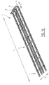
Figure 1A shows a view of a loading system with loading modules according to the invention; -
Figure 1B shows a view of a loading system with loading modules and front modules; -
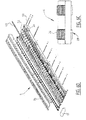
Figure 2 shows a side view of the loading system offigure 1B ; -
Figure 3 shows a detail of the spacer of the loading system offigure 1B ; -
Figure 4 shows a detail of the coupling between two modules, placed one behind the other, of the loading system infigures 1A and1B ; -
Figure 5A shows a view of a loading module of a loading system according tofigures 1A and1B ; -
Figure 5B shows a side view of a loading module offigure 5A ; -
Figure 5C shows a cross-section of the loading module offigure 5A ; -
Figure 5D shows an exploded view of the loading module offigure 5A ; -
Figures 6A-D show views of a (pneumatic) front module of the loading system offigures 1A and1B ; and -
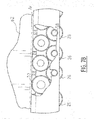
Figures 7A and B show the operating principle of the rows with roller elements in the loading systems offigures 1A and1B . - Loading system 2 (
figure 1A ) is composed of a number ofloading modules 4, preferably in combination with (pneumatic)front modules 6. Anengagement 8 is provided, whereby a forklift truck, AGV or other vehicle can transportloading system 2. If desired, it is also possible to provide a drive directly onloading system 2.Loading system 2 is further provided with push plate or pushbar 10 which is optionally movable in direction A overloading system 2. - In the shown embodiment four tracks, which are mutually connected with
spacers 16, are provided adjacently of each other.Loading system 2 extends in longitudinal direction over distance L and in width direction overdistance B. Spacers 16 connect twoadjacent tracks 12, 14 (figure 1B ). In the shownembodiment spacer 16 is configured to holdtracks - In the shown
embodiment spacer 16 is connected viabolt construction 18 toloading module 4. In the shown embodiment use is preferably made here ofspring element 20,washer 22 andcontact elements 24 of module 4 (Figure 3 ). -
First row 26 ofroller elements 28 is in contact with a ground surface during use. Positioned wholly or partially thereabove issecond row 30 of roller elements 32 (figure 2 ). In the pick-up or set-downmode roller elements 32 ofsecond row 30 can protrude wholly or partially through opening 34 arranged in carryingsurface 36. In the shownembodiment front module 6 is provided with a decreasing thickness as seen in the direction toward the front side ofloading system 2, whereinnose element 38 is arranged on the front side.Modules loading system 2 usingcoupling 40. - Coupling 40 (
figure 4 ) is a type of pin-hole connection with opening 42, connecting block 44, pins 46, 48 and spring pins 50, 52. Carryingsurface 36 is formed on the upper side bysurface 36a and in the shown embodiment is provided on the sides withbent edges - Loading module 4 (
figures 5A-D ) is provided withspace 54 between the mutually adjacent rows ofroller elements 32 ofmodule hose 56 can be placed.Roller elements module 4 usingrotation shaft 58. Further provided in the shown embodiment is closing plate 60 for mutual fixing of the components ofmodule 4. - Front module 6 (
figures 6A-D ) is constructed in similar manner, wherein in the shownembodiment roller elements 28, 33 decrease in diameter in the direction ofnose element 38 so as to thereby enable them to be inserted under the load more easily. This decrease in diameter ofroller elements - In the shown
embodiment roller elements 28, 32 (Figures 7A-B ) are provided in fixedly arranged manner and are in mutual contact withcontact surfaces 66 in both the first transport mode and the second pick-up or set-down mode.First roller elements 28 move overground surface 64 during displacement ofloading system 2, while in the pick-up or set-downmode roller elements 32 ofsecond row 30 are in contact withload 62 in that theseroller elements 32 protrude partially above carryingsurface 36 throughopenings 34 therein.Carrier plate 67 is optionally additionally provided betweenload 62 and contact surfaces 66 ofroller elements 32. If desired, it is also possible to provideground surface 64 with optional conveyor belt system 68 for automatic loading ofloading system 2. Due to movement of belt system 68load 62 is in the second pick-up or set-down mode displaced overloading system 2 while remaining in the same spatial position. - For the purpose of displacing
load 62loading system 2 is composed of a number of loading modules which are provided on the front side ofloading system 2 withfront loading modules 6.Modules couplings 40 and, in the case of a plurality oftracks B using spacers 16. - During use,
loading system 2 is inserted withnose element 38 underload 62. By placingloading system 2 in the second pick-up or set-down mode by lowering or descending of liftingelement 56 carryingsurface 36 is moved preferably maximally downward relative toroller elements roller elements 32 hereby come into contact withload 62, optionally viacarrier plate 67, and load 62 will not move, or hardly so, relative toground surface 64, while loadingsystem 2 is inserted under thisload 62. Afterload 62 has been positioned onloading system 2, liftingelement 56 is activated. In the shown embodiment activation is possible by connectinghose 56 to compressed air coupling 70 (indicated schematically infigure 1A ). By inflatinghose 56 carryingsurface 36 moves upward relative toroller elements surface 36 hereby comes to lie abovecontact surface 66 ofroller elements 32 so that theseroller elements 32 are no longer in contact withload 62. In thistransport mode load 62 is carried wholly by carryingsurface 36. By displacingloading system 2load 62 will also move along in this transport mode and will therefore move relative toground surface 64. When the desired set-down location forload 62 is reached, liftingelement 56 is deactivated, wherein in the shown embodiment air is pushed fromhose 56, for instance by making use of the weight ofload 62.Load 62 hereby comes to lie oncontact surfaces 66 ofroller elements 32. When loadingsystem 2 is withdrawn, load 62 will hereby remain substantially at the same position relative toground surface 64.Load 62 can hereby be set down at the desired location andloading system 2 can then be used to transport other goods. It is noted that it is possible to co-transportloading system 2 withload 62 in order to further simplify the logistical transport. - The present invention is by no means limited to the above described preferred embodiments thereof. The rights sought are defined by the following claims, within the scope of which many modifications can be envisaged.
Claims (12)
- Loading module for transport of goods, the loading module comprising:- a frame provided with:- a carrying surface provided with a number of openings;- a first row of roller elements provided with a rotation shaft; and- a second row of roller elements, provided with a rotation shaft, which lies above the first row of roller elements, and wherein the rotation shafts of the second row lie substantially at a greater distance from a ground surface as compared to the rotation shafts of the first row, and wherein in a first transport mode the second row of roller elements lie substantially under the carrying surface and in a second pick-up or set-down mode protrude at least partially with a contact surface through the openings in the carrying surface; and- a pneumatic and/or hydraulic lifting element arranged in the frame and configured to switch the loading module between a first transport mode and a second pick-up or set-down mode, wherein the lifting element comprises a hose-like element.
- Loading module according to claim 1, wherein the hose-like element extends in longitudinal direction of the loading module.
- Loading module according to claim 1 or 2, wherein the carrying surface is configured to move upward and/or downward in accordance with the lifting element.
- Loading module according to claim 1, 2 or 3, wherein the lifting element comprises a pneumatic lifting element.
- Loading module according to claim 4, further comprising a pneumatic coupling configured to couple the pneumatic lifting element to a compressed air source.
- Loading system, comprising one or more loading modules according to any one of the foregoing claims, and one or more front modules.
- Loading system according to claim 6, further comprising a number of spacers for connecting loading modules which are positioned adjacently of each other as seen in the usual direction of travel.
- Loading system according to claim 7, wherein the spacers are adjustable in longitudinal direction.
- Loading system according to any one of the foregoing claims 6-8, further comprising a support bar configured to hold the load in position when it is being set down.
- Loading system according to any one of the foregoing claims 6-9, further comprising a carrier plate configured to be arranged between the load and the carrying surface.
- Loading system according to any one of the foregoing claims 6-10, further comprising an automatic loading system.
- Method for transport of goods, the method comprising the steps of:- providing a loading module and/or loading system according to any one of the foregoing claims;- picking up the goods;- displacing the goods; and- setting down the goods.
Applications Claiming Priority (1)
| Application Number | Priority Date | Filing Date | Title |
|---|---|---|---|
| NL2023603A NL2023603B1 (en) | 2019-08-02 | 2019-08-02 | LOADING MODULE AND METHOD FOR TRANSPORT OF GOODS |
Publications (2)
| Publication Number | Publication Date |
|---|---|
| EP3771685A1 true EP3771685A1 (en) | 2021-02-03 |
| EP3771685B1 EP3771685B1 (en) | 2023-05-03 |
Family
ID=69187848
Family Applications (1)
| Application Number | Title | Priority Date | Filing Date |
|---|---|---|---|
| EP20189180.1A Active EP3771685B1 (en) | 2019-08-02 | 2020-08-03 | Loading module and method for transport of goods |
Country Status (2)
| Country | Link |
|---|---|
| EP (1) | EP3771685B1 (en) |
| NL (1) | NL2023603B1 (en) |
Citations (5)
| Publication number | Priority date | Publication date | Assignee | Title |
|---|---|---|---|---|
| US3549035A (en) * | 1969-04-18 | 1970-12-22 | Donald W Soper | Fork assist |
| US20040191047A1 (en) * | 2001-06-11 | 2004-09-30 | Sjoerd Meijer | Fork-lift with loading system |
| US20140301815A1 (en) * | 2011-10-12 | 2014-10-09 | Gebr. Meijer St. Jabik B.V. | Stacker and Method for Displacing Goods |
| US20160264385A1 (en) * | 2015-03-10 | 2016-09-15 | Roy C. Burrow | Convertible pallet jack with rollers |
| AU2017358322A1 (en) * | 2016-11-11 | 2019-06-13 | Dissing A/S | A device for positioning an object relatively to a support by inflatable air cushion members, a method of operating the device, and a method for moving an object |
-
2019
- 2019-08-02 NL NL2023603A patent/NL2023603B1/en active
-
2020
- 2020-08-03 EP EP20189180.1A patent/EP3771685B1/en active Active
Patent Citations (5)
| Publication number | Priority date | Publication date | Assignee | Title |
|---|---|---|---|---|
| US3549035A (en) * | 1969-04-18 | 1970-12-22 | Donald W Soper | Fork assist |
| US20040191047A1 (en) * | 2001-06-11 | 2004-09-30 | Sjoerd Meijer | Fork-lift with loading system |
| US20140301815A1 (en) * | 2011-10-12 | 2014-10-09 | Gebr. Meijer St. Jabik B.V. | Stacker and Method for Displacing Goods |
| US20160264385A1 (en) * | 2015-03-10 | 2016-09-15 | Roy C. Burrow | Convertible pallet jack with rollers |
| AU2017358322A1 (en) * | 2016-11-11 | 2019-06-13 | Dissing A/S | A device for positioning an object relatively to a support by inflatable air cushion members, a method of operating the device, and a method for moving an object |
Also Published As
| Publication number | Publication date |
|---|---|
| EP3771685B1 (en) | 2023-05-03 |
| NL2023603B1 (en) | 2021-02-23 |
Similar Documents
| Publication | Publication Date | Title |
|---|---|---|
| US8944239B2 (en) | Conveyor apparatus for loading or unloading packages from shipping containers | |
| EP0086211B1 (en) | Mechanical handling apparatus | |
| US4544319A (en) | Cargo transfer system | |
| EP1963217B1 (en) | Transfer plate and method for loading a cargo space | |
| US4261682A (en) | Loading and unloading of vehicles | |
| NL8700453A (en) | LOADING FLOOR OF A TRUCK. | |
| US7934594B2 (en) | Conveyor system for vehicle | |
| CN109264433B (en) | Automatic loading equipment and loading method | |
| EP2111349A1 (en) | Loading and unloading arrangement for a vehicle | |
| US20100061834A1 (en) | Platform for carrying and transporting loads with an unrollable floor, and transport device with a platform of this type | |
| US6368042B1 (en) | Vehicle loading and unloading system | |
| CN112299065A (en) | Whole vehicle loading system | |
| AU2054899A (en) | Loading and unloading system for cargo trucks, their trailers, transport containers and the like | |
| US20070104563A1 (en) | Materials handling system | |
| US4103789A (en) | Unitized loading system | |
| EP0276851A2 (en) | Modular aircraft loader | |
| US4440253A (en) | Crawler-type transport apparatus | |
| EP3771685A1 (en) | Loading module and method for transport of goods | |
| GB2406084A (en) | Accumulating conveyor with airbag lifting apparatus | |
| EP0000321B1 (en) | Load handling apparatus for loading and unloading of transport vehicles | |
| CN115535654A (en) | Embedded automatic container loading and unloading vehicle system | |
| NZ203397A (en) | Retractable conveyor in floor of load-carrying deck | |
| EP1028085B1 (en) | Storage area loading and unloading system | |
| US5094341A (en) | Apparatus to facilitate movement of objects over a surface | |
| EP1056663B1 (en) | Conveying system |
Legal Events
| Date | Code | Title | Description |
|---|---|---|---|
| PUAI | Public reference made under article 153(3) epc to a published international application that has entered the european phase |
Free format text: ORIGINAL CODE: 0009012 |
|
| STAA | Information on the status of an ep patent application or granted ep patent |
Free format text: STATUS: THE APPLICATION HAS BEEN PUBLISHED |
|
| AK | Designated contracting states |
Kind code of ref document: A1 Designated state(s): AL AT BE BG CH CY CZ DE DK EE ES FI FR GB GR HR HU IE IS IT LI LT LU LV MC MK MT NL NO PL PT RO RS SE SI SK SM TR |
|
| AX | Request for extension of the european patent |
Extension state: BA ME |
|
| STAA | Information on the status of an ep patent application or granted ep patent |
Free format text: STATUS: REQUEST FOR EXAMINATION WAS MADE |
|
| 17P | Request for examination filed |
Effective date: 20210624 |
|
| RBV | Designated contracting states (corrected) |
Designated state(s): AL AT BE BG CH CY CZ DE DK EE ES FI FR GB GR HR HU IE IS IT LI LT LU LV MC MK MT NL NO PL PT RO RS SE SI SK SM TR |
|
| GRAP | Despatch of communication of intention to grant a patent |
Free format text: ORIGINAL CODE: EPIDOSNIGR1 |
|
| STAA | Information on the status of an ep patent application or granted ep patent |
Free format text: STATUS: GRANT OF PATENT IS INTENDED |
|
| INTG | Intention to grant announced |
Effective date: 20221220 |
|
| GRAS | Grant fee paid |
Free format text: ORIGINAL CODE: EPIDOSNIGR3 |
|
| GRAA | (expected) grant |
Free format text: ORIGINAL CODE: 0009210 |
|
| STAA | Information on the status of an ep patent application or granted ep patent |
Free format text: STATUS: THE PATENT HAS BEEN GRANTED |
|
| AK | Designated contracting states |
Kind code of ref document: B1 Designated state(s): AL AT BE BG CH CY CZ DE DK EE ES FI FR GB GR HR HU IE IS IT LI LT LU LV MC MK MT NL NO PL PT RO RS SE SI SK SM TR |
|
| REG | Reference to a national code |
Ref country code: GB Ref legal event code: FG4D |
|
| REG | Reference to a national code |
Ref country code: AT Ref legal event code: REF Ref document number: 1564467 Country of ref document: AT Kind code of ref document: T Effective date: 20230515 Ref country code: CH Ref legal event code: EP |
|
| REG | Reference to a national code |
Ref country code: DE Ref legal event code: R096 Ref document number: 602020010316 Country of ref document: DE |
|
| REG | Reference to a national code |
Ref country code: IE Ref legal event code: FG4D |
|
| REG | Reference to a national code |
Ref country code: NL Ref legal event code: FP |
|
| P01 | Opt-out of the competence of the unified patent court (upc) registered |
Effective date: 20230526 |
|
| REG | Reference to a national code |
Ref country code: LT Ref legal event code: MG9D |
|
| PGFP | Annual fee paid to national office [announced via postgrant information from national office to epo] |
Ref country code: NL Payment date: 20230826 Year of fee payment: 4 |
|
| REG | Reference to a national code |
Ref country code: AT Ref legal event code: MK05 Ref document number: 1564467 Country of ref document: AT Kind code of ref document: T Effective date: 20230503 |
|
| PG25 | Lapsed in a contracting state [announced via postgrant information from national office to epo] |
Ref country code: SE Free format text: LAPSE BECAUSE OF FAILURE TO SUBMIT A TRANSLATION OF THE DESCRIPTION OR TO PAY THE FEE WITHIN THE PRESCRIBED TIME-LIMIT Effective date: 20230503 Ref country code: PT Free format text: LAPSE BECAUSE OF FAILURE TO SUBMIT A TRANSLATION OF THE DESCRIPTION OR TO PAY THE FEE WITHIN THE PRESCRIBED TIME-LIMIT Effective date: 20230904 Ref country code: NO Free format text: LAPSE BECAUSE OF FAILURE TO SUBMIT A TRANSLATION OF THE DESCRIPTION OR TO PAY THE FEE WITHIN THE PRESCRIBED TIME-LIMIT Effective date: 20230803 Ref country code: ES Free format text: LAPSE BECAUSE OF FAILURE TO SUBMIT A TRANSLATION OF THE DESCRIPTION OR TO PAY THE FEE WITHIN THE PRESCRIBED TIME-LIMIT Effective date: 20230503 Ref country code: AT Free format text: LAPSE BECAUSE OF FAILURE TO SUBMIT A TRANSLATION OF THE DESCRIPTION OR TO PAY THE FEE WITHIN THE PRESCRIBED TIME-LIMIT Effective date: 20230503 |
|
| PG25 | Lapsed in a contracting state [announced via postgrant information from national office to epo] |
Ref country code: RS Free format text: LAPSE BECAUSE OF FAILURE TO SUBMIT A TRANSLATION OF THE DESCRIPTION OR TO PAY THE FEE WITHIN THE PRESCRIBED TIME-LIMIT Effective date: 20230503 Ref country code: PL Free format text: LAPSE BECAUSE OF FAILURE TO SUBMIT A TRANSLATION OF THE DESCRIPTION OR TO PAY THE FEE WITHIN THE PRESCRIBED TIME-LIMIT Effective date: 20230503 Ref country code: LV Free format text: LAPSE BECAUSE OF FAILURE TO SUBMIT A TRANSLATION OF THE DESCRIPTION OR TO PAY THE FEE WITHIN THE PRESCRIBED TIME-LIMIT Effective date: 20230503 Ref country code: LT Free format text: LAPSE BECAUSE OF FAILURE TO SUBMIT A TRANSLATION OF THE DESCRIPTION OR TO PAY THE FEE WITHIN THE PRESCRIBED TIME-LIMIT Effective date: 20230503 Ref country code: IS Free format text: LAPSE BECAUSE OF FAILURE TO SUBMIT A TRANSLATION OF THE DESCRIPTION OR TO PAY THE FEE WITHIN THE PRESCRIBED TIME-LIMIT Effective date: 20230903 Ref country code: HR Free format text: LAPSE BECAUSE OF FAILURE TO SUBMIT A TRANSLATION OF THE DESCRIPTION OR TO PAY THE FEE WITHIN THE PRESCRIBED TIME-LIMIT Effective date: 20230503 Ref country code: GR Free format text: LAPSE BECAUSE OF FAILURE TO SUBMIT A TRANSLATION OF THE DESCRIPTION OR TO PAY THE FEE WITHIN THE PRESCRIBED TIME-LIMIT Effective date: 20230804 |
|
| PGFP | Annual fee paid to national office [announced via postgrant information from national office to epo] |
Ref country code: FR Payment date: 20230825 Year of fee payment: 4 Ref country code: DE Payment date: 20230829 Year of fee payment: 4 |
|
| PG25 | Lapsed in a contracting state [announced via postgrant information from national office to epo] |
Ref country code: FI Free format text: LAPSE BECAUSE OF FAILURE TO SUBMIT A TRANSLATION OF THE DESCRIPTION OR TO PAY THE FEE WITHIN THE PRESCRIBED TIME-LIMIT Effective date: 20230503 |
|
| PG25 | Lapsed in a contracting state [announced via postgrant information from national office to epo] |
Ref country code: SK Free format text: LAPSE BECAUSE OF FAILURE TO SUBMIT A TRANSLATION OF THE DESCRIPTION OR TO PAY THE FEE WITHIN THE PRESCRIBED TIME-LIMIT Effective date: 20230503 |
|
| PG25 | Lapsed in a contracting state [announced via postgrant information from national office to epo] |
Ref country code: SM Free format text: LAPSE BECAUSE OF FAILURE TO SUBMIT A TRANSLATION OF THE DESCRIPTION OR TO PAY THE FEE WITHIN THE PRESCRIBED TIME-LIMIT Effective date: 20230503 Ref country code: SK Free format text: LAPSE BECAUSE OF FAILURE TO SUBMIT A TRANSLATION OF THE DESCRIPTION OR TO PAY THE FEE WITHIN THE PRESCRIBED TIME-LIMIT Effective date: 20230503 Ref country code: RO Free format text: LAPSE BECAUSE OF FAILURE TO SUBMIT A TRANSLATION OF THE DESCRIPTION OR TO PAY THE FEE WITHIN THE PRESCRIBED TIME-LIMIT Effective date: 20230503 Ref country code: EE Free format text: LAPSE BECAUSE OF FAILURE TO SUBMIT A TRANSLATION OF THE DESCRIPTION OR TO PAY THE FEE WITHIN THE PRESCRIBED TIME-LIMIT Effective date: 20230503 Ref country code: DK Free format text: LAPSE BECAUSE OF FAILURE TO SUBMIT A TRANSLATION OF THE DESCRIPTION OR TO PAY THE FEE WITHIN THE PRESCRIBED TIME-LIMIT Effective date: 20230503 Ref country code: CZ Free format text: LAPSE BECAUSE OF FAILURE TO SUBMIT A TRANSLATION OF THE DESCRIPTION OR TO PAY THE FEE WITHIN THE PRESCRIBED TIME-LIMIT Effective date: 20230503 |
|
| REG | Reference to a national code |
Ref country code: DE Ref legal event code: R097 Ref document number: 602020010316 Country of ref document: DE |
|
| PLBE | No opposition filed within time limit |
Free format text: ORIGINAL CODE: 0009261 |
|
| STAA | Information on the status of an ep patent application or granted ep patent |
Free format text: STATUS: NO OPPOSITION FILED WITHIN TIME LIMIT |
|
| PG25 | Lapsed in a contracting state [announced via postgrant information from national office to epo] |
Ref country code: MC Free format text: LAPSE BECAUSE OF FAILURE TO SUBMIT A TRANSLATION OF THE DESCRIPTION OR TO PAY THE FEE WITHIN THE PRESCRIBED TIME-LIMIT Effective date: 20230503 |
|
| REG | Reference to a national code |
Ref country code: CH Ref legal event code: PL |
|
| PG25 | Lapsed in a contracting state [announced via postgrant information from national office to epo] |
Ref country code: MC Free format text: LAPSE BECAUSE OF FAILURE TO SUBMIT A TRANSLATION OF THE DESCRIPTION OR TO PAY THE FEE WITHIN THE PRESCRIBED TIME-LIMIT Effective date: 20230503 |
|
| 26N | No opposition filed |
Effective date: 20240206 |
|
| PG25 | Lapsed in a contracting state [announced via postgrant information from national office to epo] |
Ref country code: LU Free format text: LAPSE BECAUSE OF NON-PAYMENT OF DUE FEES Effective date: 20230803 |
|
| PG25 | Lapsed in a contracting state [announced via postgrant information from national office to epo] |
Ref country code: LU Free format text: LAPSE BECAUSE OF NON-PAYMENT OF DUE FEES Effective date: 20230803 Ref country code: CH Free format text: LAPSE BECAUSE OF NON-PAYMENT OF DUE FEES Effective date: 20230831 |
|
| PG25 | Lapsed in a contracting state [announced via postgrant information from national office to epo] |
Ref country code: SI Free format text: LAPSE BECAUSE OF FAILURE TO SUBMIT A TRANSLATION OF THE DESCRIPTION OR TO PAY THE FEE WITHIN THE PRESCRIBED TIME-LIMIT Effective date: 20230503 |
|
| REG | Reference to a national code |
Ref country code: BE Ref legal event code: MM Effective date: 20230831 |
|
| REG | Reference to a national code |
Ref country code: IE Ref legal event code: MM4A |
|
| PG25 | Lapsed in a contracting state [announced via postgrant information from national office to epo] |
Ref country code: SI Free format text: LAPSE BECAUSE OF FAILURE TO SUBMIT A TRANSLATION OF THE DESCRIPTION OR TO PAY THE FEE WITHIN THE PRESCRIBED TIME-LIMIT Effective date: 20230503 Ref country code: IT Free format text: LAPSE BECAUSE OF FAILURE TO SUBMIT A TRANSLATION OF THE DESCRIPTION OR TO PAY THE FEE WITHIN THE PRESCRIBED TIME-LIMIT Effective date: 20230503 |
|
| PG25 | Lapsed in a contracting state [announced via postgrant information from national office to epo] |
Ref country code: IE Free format text: LAPSE BECAUSE OF NON-PAYMENT OF DUE FEES Effective date: 20230803 |
|
| PG25 | Lapsed in a contracting state [announced via postgrant information from national office to epo] |
Ref country code: IE Free format text: LAPSE BECAUSE OF NON-PAYMENT OF DUE FEES Effective date: 20230803 |
|
| PG25 | Lapsed in a contracting state [announced via postgrant information from national office to epo] |
Ref country code: BE Free format text: LAPSE BECAUSE OF NON-PAYMENT OF DUE FEES Effective date: 20230831 |