EP3771648A1 - Predictive aircraft passenger cabin service system and method - Google Patents
Predictive aircraft passenger cabin service system and method Download PDFInfo
- Publication number
- EP3771648A1 EP3771648A1 EP19215958.0A EP19215958A EP3771648A1 EP 3771648 A1 EP3771648 A1 EP 3771648A1 EP 19215958 A EP19215958 A EP 19215958A EP 3771648 A1 EP3771648 A1 EP 3771648A1
- Authority
- EP
- European Patent Office
- Prior art keywords
- passenger
- condition changes
- sensors
- objects
- service
- Prior art date
- Legal status (The legal status is an assumption and is not a legal conclusion. Google has not performed a legal analysis and makes no representation as to the accuracy of the status listed.)
- Pending
Links
- 238000000034 method Methods 0.000 title description 10
- 230000009471 action Effects 0.000 claims abstract description 43
- 238000012545 processing Methods 0.000 claims abstract description 17
- 230000000694 effects Effects 0.000 claims abstract description 4
- 238000012544 monitoring process Methods 0.000 claims abstract 2
- 230000008859 change Effects 0.000 claims description 29
- 230000000007 visual effect Effects 0.000 claims description 9
- 230000004043 responsiveness Effects 0.000 claims description 3
- 230000033001 locomotion Effects 0.000 description 17
- 238000004891 communication Methods 0.000 description 9
- 230000004044 response Effects 0.000 description 8
- 230000000875 corresponding effect Effects 0.000 description 6
- 230000007613 environmental effect Effects 0.000 description 6
- 230000003287 optical effect Effects 0.000 description 5
- 230000008569 process Effects 0.000 description 5
- 235000013305 food Nutrition 0.000 description 4
- 239000000126 substance Substances 0.000 description 4
- 230000002618 waking effect Effects 0.000 description 4
- 238000004422 calculation algorithm Methods 0.000 description 3
- 230000001934 delay Effects 0.000 description 3
- 238000010586 diagram Methods 0.000 description 3
- 230000006870 function Effects 0.000 description 3
- 230000007246 mechanism Effects 0.000 description 3
- 238000012986 modification Methods 0.000 description 3
- 230000004048 modification Effects 0.000 description 3
- 230000002596 correlated effect Effects 0.000 description 2
- 238000005516 engineering process Methods 0.000 description 2
- 238000007726 management method Methods 0.000 description 2
- 235000012054 meals Nutrition 0.000 description 2
- 239000010813 municipal solid waste Substances 0.000 description 2
- 238000003908 quality control method Methods 0.000 description 2
- 230000005355 Hall effect Effects 0.000 description 1
- 235000014676 Phragmites communis Nutrition 0.000 description 1
- 230000004913 activation Effects 0.000 description 1
- 230000000454 anti-cipatory effect Effects 0.000 description 1
- 235000013361 beverage Nutrition 0.000 description 1
- 230000000903 blocking effect Effects 0.000 description 1
- 239000000872 buffer Substances 0.000 description 1
- 238000004590 computer program Methods 0.000 description 1
- 238000012790 confirmation Methods 0.000 description 1
- 238000013523 data management Methods 0.000 description 1
- 239000000835 fiber Substances 0.000 description 1
- 230000010006 flight Effects 0.000 description 1
- 230000001939 inductive effect Effects 0.000 description 1
- 230000003993 interaction Effects 0.000 description 1
- 238000005259 measurement Methods 0.000 description 1
- 230000008439 repair process Effects 0.000 description 1
- 239000004065 semiconductor Substances 0.000 description 1
- 230000007704 transition Effects 0.000 description 1
- 230000001755 vocal effect Effects 0.000 description 1
Images


Classifications
-
- B—PERFORMING OPERATIONS; TRANSPORTING
- B64—AIRCRAFT; AVIATION; COSMONAUTICS
- B64D—EQUIPMENT FOR FITTING IN OR TO AIRCRAFT; FLIGHT SUITS; PARACHUTES; ARRANGEMENTS OR MOUNTING OF POWER PLANTS OR PROPULSION TRANSMISSIONS IN AIRCRAFT
- B64D11/00—Passenger or crew accommodation; Flight-deck installations not otherwise provided for
- B64D11/0015—Arrangements for entertainment or communications, e.g. radio, television
-
- G—PHYSICS
- G06—COMPUTING; CALCULATING OR COUNTING
- G06Q—INFORMATION AND COMMUNICATION TECHNOLOGY [ICT] SPECIALLY ADAPTED FOR ADMINISTRATIVE, COMMERCIAL, FINANCIAL, MANAGERIAL OR SUPERVISORY PURPOSES; SYSTEMS OR METHODS SPECIALLY ADAPTED FOR ADMINISTRATIVE, COMMERCIAL, FINANCIAL, MANAGERIAL OR SUPERVISORY PURPOSES, NOT OTHERWISE PROVIDED FOR
- G06Q10/00—Administration; Management
- G06Q10/06—Resources, workflows, human or project management; Enterprise or organisation planning; Enterprise or organisation modelling
- G06Q10/063—Operations research, analysis or management
- G06Q10/0631—Resource planning, allocation, distributing or scheduling for enterprises or organisations
- G06Q10/06315—Needs-based resource requirements planning or analysis
-
- B—PERFORMING OPERATIONS; TRANSPORTING
- B60—VEHICLES IN GENERAL
- B60Q—ARRANGEMENT OF SIGNALLING OR LIGHTING DEVICES, THE MOUNTING OR SUPPORTING THEREOF OR CIRCUITS THEREFOR, FOR VEHICLES IN GENERAL
- B60Q1/00—Arrangement of optical signalling or lighting devices, the mounting or supporting thereof or circuits therefor
-
- B—PERFORMING OPERATIONS; TRANSPORTING
- B60—VEHICLES IN GENERAL
- B60Q—ARRANGEMENT OF SIGNALLING OR LIGHTING DEVICES, THE MOUNTING OR SUPPORTING THEREOF OR CIRCUITS THEREFOR, FOR VEHICLES IN GENERAL
- B60Q3/00—Arrangement of lighting devices for vehicle interiors; Lighting devices specially adapted for vehicle interiors
- B60Q3/30—Arrangement of lighting devices for vehicle interiors; Lighting devices specially adapted for vehicle interiors for compartments other than passenger or driving compartments, e.g. luggage or engine compartments
-
- B—PERFORMING OPERATIONS; TRANSPORTING
- B60—VEHICLES IN GENERAL
- B60Q—ARRANGEMENT OF SIGNALLING OR LIGHTING DEVICES, THE MOUNTING OR SUPPORTING THEREOF OR CIRCUITS THEREFOR, FOR VEHICLES IN GENERAL
- B60Q3/00—Arrangement of lighting devices for vehicle interiors; Lighting devices specially adapted for vehicle interiors
- B60Q3/40—Arrangement of lighting devices for vehicle interiors; Lighting devices specially adapted for vehicle interiors specially adapted for specific vehicle types
-
- B—PERFORMING OPERATIONS; TRANSPORTING
- B64—AIRCRAFT; AVIATION; COSMONAUTICS
- B64D—EQUIPMENT FOR FITTING IN OR TO AIRCRAFT; FLIGHT SUITS; PARACHUTES; ARRANGEMENTS OR MOUNTING OF POWER PLANTS OR PROPULSION TRANSMISSIONS IN AIRCRAFT
- B64D45/00—Aircraft indicators or protectors not otherwise provided for
-
- B—PERFORMING OPERATIONS; TRANSPORTING
- B64—AIRCRAFT; AVIATION; COSMONAUTICS
- B64F—GROUND OR AIRCRAFT-CARRIER-DECK INSTALLATIONS SPECIALLY ADAPTED FOR USE IN CONNECTION WITH AIRCRAFT; DESIGNING, MANUFACTURING, ASSEMBLING, CLEANING, MAINTAINING OR REPAIRING AIRCRAFT, NOT OTHERWISE PROVIDED FOR; HANDLING, TRANSPORTING, TESTING OR INSPECTING AIRCRAFT COMPONENTS, NOT OTHERWISE PROVIDED FOR
- B64F5/00—Designing, manufacturing, assembling, cleaning, maintaining or repairing aircraft, not otherwise provided for; Handling, transporting, testing or inspecting aircraft components, not otherwise provided for
- B64F5/60—Testing or inspecting aircraft components or systems
-
- G06Q50/40—
-
- G—PHYSICS
- G08—SIGNALLING
- G08B—SIGNALLING OR CALLING SYSTEMS; ORDER TELEGRAPHS; ALARM SYSTEMS
- G08B5/00—Visible signalling systems, e.g. personal calling systems, remote indication of seats occupied
-
- G—PHYSICS
- G08—SIGNALLING
- G08B—SIGNALLING OR CALLING SYSTEMS; ORDER TELEGRAPHS; ALARM SYSTEMS
- G08B5/00—Visible signalling systems, e.g. personal calling systems, remote indication of seats occupied
- G08B5/22—Visible signalling systems, e.g. personal calling systems, remote indication of seats occupied using electric transmission; using electromagnetic transmission
- G08B5/222—Personal calling arrangements or devices, i.e. paging systems
-
- G—PHYSICS
- G08—SIGNALLING
- G08B—SIGNALLING OR CALLING SYSTEMS; ORDER TELEGRAPHS; ALARM SYSTEMS
- G08B5/00—Visible signalling systems, e.g. personal calling systems, remote indication of seats occupied
- G08B5/22—Visible signalling systems, e.g. personal calling systems, remote indication of seats occupied using electric transmission; using electromagnetic transmission
- G08B5/36—Visible signalling systems, e.g. personal calling systems, remote indication of seats occupied using electric transmission; using electromagnetic transmission using visible light sources
-
- B—PERFORMING OPERATIONS; TRANSPORTING
- B64—AIRCRAFT; AVIATION; COSMONAUTICS
- B64D—EQUIPMENT FOR FITTING IN OR TO AIRCRAFT; FLIGHT SUITS; PARACHUTES; ARRANGEMENTS OR MOUNTING OF POWER PLANTS OR PROPULSION TRANSMISSIONS IN AIRCRAFT
- B64D11/00—Passenger or crew accommodation; Flight-deck installations not otherwise provided for
- B64D11/06—Arrangements of seats, or adaptations or details specially adapted for aircraft seats
- B64D11/0602—Seat modules, i.e. seat systems including furniture separate from the seat itself
-
- B—PERFORMING OPERATIONS; TRANSPORTING
- B64—AIRCRAFT; AVIATION; COSMONAUTICS
- B64D—EQUIPMENT FOR FITTING IN OR TO AIRCRAFT; FLIGHT SUITS; PARACHUTES; ARRANGEMENTS OR MOUNTING OF POWER PLANTS OR PROPULSION TRANSMISSIONS IN AIRCRAFT
- B64D11/00—Passenger or crew accommodation; Flight-deck installations not otherwise provided for
- B64D11/06—Arrangements of seats, or adaptations or details specially adapted for aircraft seats
- B64D11/0606—Arrangements of seats, or adaptations or details specially adapted for aircraft seats with privacy shells, screens, separators or the like
-
- B—PERFORMING OPERATIONS; TRANSPORTING
- B64—AIRCRAFT; AVIATION; COSMONAUTICS
- B64D—EQUIPMENT FOR FITTING IN OR TO AIRCRAFT; FLIGHT SUITS; PARACHUTES; ARRANGEMENTS OR MOUNTING OF POWER PLANTS OR PROPULSION TRANSMISSIONS IN AIRCRAFT
- B64D11/00—Passenger or crew accommodation; Flight-deck installations not otherwise provided for
- B64D11/06—Arrangements of seats, or adaptations or details specially adapted for aircraft seats
- B64D11/0626—Arrangements of seats, or adaptations or details specially adapted for aircraft seats with individual temperature or ventilation control
-
- B—PERFORMING OPERATIONS; TRANSPORTING
- B64—AIRCRAFT; AVIATION; COSMONAUTICS
- B64D—EQUIPMENT FOR FITTING IN OR TO AIRCRAFT; FLIGHT SUITS; PARACHUTES; ARRANGEMENTS OR MOUNTING OF POWER PLANTS OR PROPULSION TRANSMISSIONS IN AIRCRAFT
- B64D11/00—Passenger or crew accommodation; Flight-deck installations not otherwise provided for
- B64D11/06—Arrangements of seats, or adaptations or details specially adapted for aircraft seats
- B64D11/0638—Arrangements of seats, or adaptations or details specially adapted for aircraft seats with foldable tables, trays or cup holders
-
- B—PERFORMING OPERATIONS; TRANSPORTING
- B64—AIRCRAFT; AVIATION; COSMONAUTICS
- B64D—EQUIPMENT FOR FITTING IN OR TO AIRCRAFT; FLIGHT SUITS; PARACHUTES; ARRANGEMENTS OR MOUNTING OF POWER PLANTS OR PROPULSION TRANSMISSIONS IN AIRCRAFT
- B64D11/00—Passenger or crew accommodation; Flight-deck installations not otherwise provided for
- B64D11/06—Arrangements of seats, or adaptations or details specially adapted for aircraft seats
- B64D11/0639—Arrangements of seats, or adaptations or details specially adapted for aircraft seats with features for adjustment or converting of seats
-
- B—PERFORMING OPERATIONS; TRANSPORTING
- B64—AIRCRAFT; AVIATION; COSMONAUTICS
- B64D—EQUIPMENT FOR FITTING IN OR TO AIRCRAFT; FLIGHT SUITS; PARACHUTES; ARRANGEMENTS OR MOUNTING OF POWER PLANTS OR PROPULSION TRANSMISSIONS IN AIRCRAFT
- B64D45/00—Aircraft indicators or protectors not otherwise provided for
- B64D2045/007—Indicators or signs in the cabin, e.g. exit signs or seat numbering
Definitions
- Passenger needs may include, for example, food, drink, privacy, sleep, comfort and technology requests, among others.
- flight crew actions are typically on-demand responsive to individual passenger requests. Requests may be initiated by passengers via verbal communications to the flight crew, service crew call buttons, etc. Such modes of communication have inherent delays in response times because of the ways in which requests are made and processed, the number of outstanding requests, flight crew member availability, flight crew interactions, etc.
- a traveling passenger waking from a sleep may have an immediate need for a sitting position change, bedding removal, food or drink.
- a traveling passenger finished with a meal may have an immediate need for meal tray and trash removal.
- attention to these needs is provided by the flight crew in response to a passenger-initiated request. Requests must first be noticed by the flight crew before the flight crew can visit the passenger to determine the need before ultimately acting to address the need. Such processes and delays are undesirable to traveling passengers, and particularly those paying premium fares.
- the present invention provides a according to claim 1.
- the processing system is configured to correlate using the table the condition changes of the objects with the predetermined service issues, retrieve from the table the actions to be completed by the service crew members corresponding to the predetermined service issues, and indicate through the device the actions to be completed by the service crew members responsive to the condition changes of the objects.
- the system further comprises individual passenger suites positioned in the aircraft cabin environment, for example embodied as an aircraft passenger cabin environment, each of the passenger suites including an adjustable passenger seat, a suite door, and at least one suite amenity, wherein sensors include at least one first sensor operable for sensing a position change of the adjustable passenger seat, at least one second sensor operable for sensing a position change of the suite door, and at least one third sensor operable for sensing a condition change of the at least one suite amenity.
- the device includes a display, wherein the received condition changes are visually displayed on the device, and wherein the actions to be completed by the service crew members are visually displayed on the device.
- the device includes a display and the device is configured to visually display a virtual floorplan of the aircraft cabin environment including individual passenger suites, wherein the objects are associated with at least one of seats, furniture, amenities and passengers within or part of the individual passenger suites, and wherein condition changes of the objects are visually displayed on the virtual floorplan in real-time.
- the device is a wall-mounted display positionable in a crew service area within the aircraft cabin environment.
- the device is a handheld device including a display, a display positionable in a crew service area, or a wearable device.
- the sensors include one or more of visual sensors, position sensors, and status sensors.
- the processor is further configured to reconcile received condition changes of objects with predetermined time values associated with the predetermined service issues, such that time values exceeding predetermined time values cause the processor to indicate, through the device, the received condition changes of the objects, and time values less than the predetermined time values cause the processor not to indicate, through the device, the received condition changes of the objects.
- the processor is further configured to confirm, through the device, that an action to be completed by the service crew members responsive to the condition changes of the objects has been completed, and record, in the memory of the computer, responsiveness criteria of the service crew members associated with the actions to be completed by the service crew members.
- the processor is further configured to communicate with a passenger manifest including passenger preferences and modify the condition changes of the objects according to the passenger preferences.
- system comprises a table stored in a memory of a computer including actions to be completed by service crew members responsive to the predetermined service issues and processing circuitry communicatively coupled to the memory.
- the processing circuitry is further configured to correlate using a table the condition changes of the objects with the predetermined service issues, retrieve from the table actions to be completed by the service crew members responsive to the predetermined service issues, and indicate through the device the actions to be completed by the service crew members responsive to the condition changes of the objects.
- the system further includes passenger suites positioned in the aircraft cabin environment, for example embodied as an aircraft passenger cabin environment, each of the passenger suites including an adjustable passenger seat, a suite door, and at least one suite amenity, wherein the sensors include at least one first sensor operable for sensing a position change of the adjustable passenger seat, at least one second sensor operable for sensing a position change of the suite door, and at least one third sensor operable for sensing a condition change of the at least one suite amenity.
- the sensors include at least one first sensor operable for sensing a position change of the adjustable passenger seat, at least one second sensor operable for sensing a position change of the suite door, and at least one third sensor operable for sensing a condition change of the at least one suite amenity.
- the processor is further configured to reconcile received condition changes of objects with predetermined time values associated with the predetermined service issues, such that time values exceeding predetermined time values cause the processor to indicate, through the device, the received condition changes of the objects, and time values less than the predetermined time values cause the processor not to indicate, through the device, the received condition changes of the objects.
- the processor if further configured to at least one of confirm through the device that an action to be completed by the service crew members responsive to the condition changes of the objects has been completed, record responsiveness criteria of the service crew members associated with the actions to be completed by the service crew members, and communicate with a passenger manifest including passenger preferences and modify the condition changes of the objects according to the passenger preferences.
- Embodiments of the present invention can include one or more or any combination of the above aspects, features, and configurations.
- Immediate future needs may be, for example, predicted needs associated with a condition change such as a passenger, object, environment or activity change. Immediate future needs may be correlated with predetermined flight crew actions responsive to the condition changes within the passenger cabin environment.
- Data within the networked system may be streamed from sensors and sensor networks positioned in the aircraft cabin environment, for example, within or in proximity to seats, suites, lavatories, furniture and other objects. Sensors may monitor object movements such as position and geometry changes and may communicate with other sensors in the system such as those associated with seat actuation or other strategically positioned sensors. Sensing may also include streaming passenger location positioning using image processing and a sensor or an array of sensors.
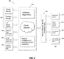
- FIG. 1 depicts a first configuration of a predictive cabin service system generally at reference numeral 100.
- sensors 102 of one or more sensor networks are positioned within the aircraft cabin environment.
- sensor networks may be positioned in relation to and associated with one or more of passenger seats, passenger suites, lavatories, overhead stowage bins, closets, amenities, furniture, electronic equipment, etc.
- Sensor networks may also be positioned in relation to predetermined areas to be monitored within the passenger cabin environment.
- Each sensor, sensor array or sensor network is configured to sense a condition change within the aircraft cabin environment.
- Condition changes may include, but are not limited to, object movements, passenger movements, environmental changes, activity changes, equipment changes, etc.
- Each condition change to be monitored determines the type(s) of sensor, sensor array and sensor network required.
- Sensors utilized in the systems according to the present invention may include, but are not limited to, acoustic sensors, chemical sensors, electrical sensors, environmental sensors, position sensors, optical sensors, pressure sensors, force sensors, temperature sensors, and proximity sensors.
- Acoustic sensors may be utilized to detect noise levels in a predetermined area of the aircraft cabin environment, such as within an individual passenger suite, for device control, comfort, privacy, etc.
- Chemical sensors may be utilized to monitor the environment.
- Electrical sensors may be utilized to detect electrical equipment status or mode changes, or may be electrically coupled with seat control systems to monitor condition changes corresponding to technology needs, comfort, etc.
- Environmental sensors may be utilized to monitor discrete sections of the aircraft cabin environment and may be coordinated with other local sensor systems.
- Temperature sensors may be utilized to predict passenger comfort needs. The remaining sensor types may be utilized, for example, to detect position and geometry changes in the aircraft cabin environment to predict all types of passenger needs.
- a variety of sensors may be mounted onto or within objects to monitor position.
- a gyroscopic sensor or gyro sensor may be used to identify the orientation of an object including the sensor.
- An orientation sensor provides information regarding position in comparison to a reference plane.
- orientation sensors include rotary encoders and inclinometers.
- a Hall effect sensor may be used to determine proximity to a magnetic field, which can be translated to a range of positions.
- Other proximity sensors include optical, capacitive, and inductive proximity sensors.
- a reed switch is opened or closed by a magnetic field, such that a binary position (e.g., in this orientation, not in this orientation) may be readily determined based upon a switch position.
- an optical switch may be used to determine whether a beam of light has been broken, which can translate to whether a certain object is in a particular position or not.
- sensors utilized in the exemplary system shown may include sensors of the above types such as visual sensors 104, position sensors 106, and status sensors 108.
- Each sensor may be a device or a subsystem capable of detecting condition changes within the aircraft cabin environment and communicating with a processor 110.
- visual sensors 104 may detect objects and/or passengers to detect presence or absence and to track movements.
- Position sensors 106 may detect positional or geometry changes of objects.
- Status sensors 108 may detect operational modes or status of devices.
- the system sensors 102 relay information to the system processor 110 where processing logic analyzes the data received to confirm service issues corresponding to predictive actions.
- the processor 110 may be a component of a server, such as a digital computer also including input/output (I/O) interfaces, a network interface, a data store, and memory.
- the components may be communicatively coupled via a local interface such as one or more buses or other wired or wireless connections.
- the local interface may have additional elements such as controllers, buffers (caches), drivers, repeaters, and receivers, among others, to enable communications. Further, the local interface may include address, control, and/or data connections to enable appropriate communications among the components.
- the processor 110 is a hardware device for executing software instructions such as collation algorithms.
- the processor 110 may be any custom made or commercially available processor, a central processing unit (CPU), an auxiliary processor among several processors associated with the server, a semiconductor-based microprocessor (in the form of a microchip or chip set), or generally any device for executing software instructions.
- the processor is configured to execute software stored within the memory, to communicate data to and from the memory, and to generally control operations of the server pursuant to the software instructions.
- the I/O interfaces may be used to receive user input from and/or for providing system output to one or more devices or components such as the sensors 102, an aircraft network 112, and flight crew devices 114.
- I/O interfaces may include a serial port, a parallel port, a small computer system interface (SCSI), a serial ATA (SATA), a fibre channel, Infiniband, iSCSI, a PCI Express interface (PCI-x), an infrared (IR) interface, a radio frequency (RF) interface, and/or a universal serial bus (USB) interface.
- SCSI small computer system interface
- SATA serial ATA
- PCI-x PCI Express interface
- IR infrared
- RF radio frequency
- USB universal serial bus
- the network interface may be used to enable the server to communicate on a network, such as the Internet, a wide area network (WAN), a local area network (LAN) such as the secure aircraft network 112, and the like, etc.
- the network interface may include address, control, and/or data connections to enable appropriate communications on the network.
- a data store may be used to store data.
- the data store may include any of volatile memory elements (e.g., random access memory (RAM, such as DRAM, SRAM, SDRAM, and the like)), nonvolatile memory elements (e.g., ROM, hard drive, tape, CDROM, and the like), and combinations thereof.
- the data store may incorporate electronic, magnetic, optical, and/or other types of storage media.
- the data store may be located internal to the server such as, for example, an internal hard drive connected to the local interface in the server. Additionally, in another embodiment, the data store may be located external to the server such as, for example, an external hard drive connected to the I/O interfaces (e.g., SCSI or USB connection). In a further embodiment, the data store may be connected to the server through a network, such as, for example, a network attached file server.
- a network such as, for example, a network attached file server.
- the memory may include any of volatile memory elements (e.g., random access memory (RAM, such as DRAM, SRAM, SDRAM, etc.)), nonvolatile memory elements (e.g., ROM, hard drive, tape, CDROM, etc.), and combinations thereof. Moreover, the memory may incorporate electronic, magnetic, optical, and/or other types of storage media.
- the software in memory may include one or more software programs, each of which includes an ordered listing of executable instructions for implementing logical functions.
- the software in the memory includes a suitable operating system (O/S) and one or more programs.
- the operating system essentially controls the execution of other computer programs, such as the one or more programs, and provides scheduling, input-output control, file and data management, memory management, and communication control and related services.
- the one or more programs may be configured to implement the various processes, algorithms, methods, techniques, etc. described herein.
- the flight crew devices 114 may be digital devices that, in terms of hardware architecture, include a processor, input/output (I/O) interfaces, a data store, a memory and a display.
- the flight crew devices 114 may include one or more of mobile handheld devices 116, centrally located cabin display devices 118, wearable devices 120, and in-ear or other body mounted devices 122.
- the active system may include one or more of these device types to ensure that the flight crew is made aware of, by redundant communications to the various devices, indicated service issues in a timely manner to minimize response time delays.
- Mobile flight crew devices may be enabled for wireless communication to an external access device or network.
- the data store may be used to store data.
- the memory may include any of volatile memory elements, nonvolatile memory elements, and combinations thereof. Programs can include an application or "app" which provides various functionality.
- condition changes are monitored and information conveyed to the processor 110.
- the main routine of the processor 110 operates to receive and analyze the condition changes to determine the occurrence of a qualifying condition change corresponding to a predetermined service issue. Predetermined service issues are correlated to actions to be considered or performed on the part of the flight crew to attend to a potential passenger need.
- the processor 110 may communicate with a look-up table stored in the sever memory containing the list of qualifying condition changes and responsive actions.
- the processor Upon confirmation of a qualifying service issue, the processor operates to send an instruction to one or more of the flight crew devices 116 to cause the one or more devices to display at least one of the condition change, service issue, and predetermined flight crew actions responsive to the service issue.
- Flight crew actions are actions to be considered, and more likely actions to be performed by the flight crew responsive to an indicated service issue. Flight crew actions may be stored on the look-up table corresponding to the service issues and condition changes. In some embodiments, the flight crew actions are pre-programmed and predetermined. In some embodiments, the flight crew may have the ability to modify the flight crew actions, through the flight crew devices 116 or another avenue, based on passenger preferences and historical data. For example, a passenger may desire a specific flight crew action, different from the preprogrammed action(s), responsive to a particular service issue. In the case of preferences, modifications can be made or notes can be added to the look-up table specific for that traveling passenger in embodiments in which the look-up table is modifiable. Modifications may be stored in memory and tagged or otherwise associated with passenger information by way of name, frequent flyer number or other passenger identifier, to better serve a passenger for the remainder of the flight and on future flights.
- FIG. 2 depicts a second configuration of a predictive cabin service system generally at reference numeral 200.
- the second system 200 includes sensors 102, a processor 210, a secure aircraft network 112, and one or more flight crew devices 114.
- the second system 200 further includes information or access to one or more of frequent flyer information 202, social media and travel data 204, and previous historical data 206 such as flight crew notations and modifications.
- the processing logic is further configured to access one or more of the additional information sources to potentially modify the indication or the flight crew action(s).
- a passenger manifest may be used to update the look-up table with passenger preferences to modify one or more of the indications and flight crew actions.
- a different passenger may prefer not to be disturbed for a predetermined period of time after waking.
- a default setting may be a flight crew action to attend to a passenger within a short time period
- a preference setting may be used to set or indicate a delay to a flight crew action.
- the external information sources including the frequent flyer information 202, social media information 204, and previous historical data 206 may be factors for correlating or modifying flight crew actions.
- the system may be configured with a form fillable by passengers to set specific preferences, wherein the processing logic is configured to process the forms and update indications or actions based on the passenger preferences.
- FIG. 3 depicts a feedback loop sub-routine 300 executable by the processor (110, 210).
- the flight crew and/or the passengers may interact, manually or automatically, with the system (100, 200) to provide feedback to the airline. Feedback may include responsive to indications, response times, passenger satisfaction, etc.
- the feedback loop sub-routine may be a component of the system (100, 200) executable by the processor, or may a separate sub-system.
- the flight crew may be tasked with entering or confirming a response to an indicated service issue via one of the flight crew devices 114, such that response time and response action can be measured, gauged and reported for quality control or other purposes.
- the system may be remotely accessed by passengers post-flight for passenger feedback for quality control.
- each seat itself may include an articulating sitting mechanism that supports a cushioned seat bottom, backrest, leg rest and headrest.
- Embedded in this adjustable mechanism may be touch interfaces, motors and actuators that move the overall seat from sitting to bed through intermediate lounge positions.
- Such mechanisms may utilize sensors in connection with power, position, orientation and status.
- Other systems and subsystems may be utilized in surrounding furniture and stowage.
- doors, tray tables and various stowages may move or have moving components such as lids and doors.
- Sensor systems and subsystems may be embedded in these mechanical objects for wired or wireless communication with the system.
- Electronic equipment such as in-flight entertainment equipment (IFE) may also be equipped with sensors and incorporate software that reacts to inputs. Not limited to seats, furniture, mechanical objects, electronics and the immediate surrounding environment, there may be other areas within the aircraft passenger cabin environment in which the predictive cabin service system operates to sense condition changes to alert the flight crew to attend to a service issue.
- IFE in-flight entertainment equipment
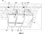
- FIG. 4 depicts a portion of an aircraft passenger cabin environment 400 including a layout of individual passenger suites 402A, 402B in a repeat one in front of the other.
- Each passenger suite 402A, 402B is generally defined by one or more privacy walls 404.
- Each passenger suite 402A, 402B has direct aisle access through an entrance 406 formed by a break in the privacy walls 404 or between spaced privacy walls of longitudinally adjacent suites.
- the entrance 406 can be opened or closed utilizing a moveable door 408 such as a sliding door configured to slide along rails.
- each suite further includes an adjustable seat and amenities positioned within the suite interior.
- Networked sensors are embedded in one or more of the seat, seat surrounds, and in adjacent locations to sense condition changes such as position changes and passenger movements.
- a first subset of sensors includes position sensors configured to sense condition changes including door movements.
- Each individual suite 402A, 402B may be equipped with position sensors configured to obtain position measurements of the doors, either absolute or relative.
- a sensor 410 may be located on the door 408 and a counterpart sensor may be located on a surround or stationary privacy wall.
- the sensors may be contact or non-contact sensors and a position change of one sensor relative to the other in a first direction may indicate door closing movement, while a position change of one sensor relative to the other in a second direction opposite the first direction may indicate door opening movement.
- the aircraft passenger cabin environment 400 may further include a second subset of sensors 412 configured to sense seat or passenger movement.
- the sensors of the second subset of sensors 412 may include, for example, infra-red, video or like sensors for visual capture of objects.
- door opening movement may trigger a sensor of the first subset
- the seat moving to an upright sitting position may trigger a sensor of the second subset
- the system may coordinate sensor outputs from the two subset to indicate a service issue to the flight crew.
- the aircraft passenger cabin environment 400 may further include a third subset of sensors 414 located in the ceiling above the passenger suites 402A, 402B.
- Each sensor 414 may be configured to monitor the suite, a specific object within the suite, the passenger, or the suite environment utilizing one or more of position, vision, chemical and environmental sensors.
- FIGS. 5A and 5B depict a portion of an aircraft passenger cabin environment 500 including a layout of individual passenger suites 502A, 502B.
- a first subset of sensors 504 may be positioned to sense condition changes of the suite doors 506 such as door opening and closing, which may be condition changes indicating predetermined service issues linked with responsive actions to be completed by the flight crew.
- the first subset of sensors 504 may also be used to indicate door position and latching to comply with TTOL requirements.
- a second subset of sensors 508 may be located in the ceiling and may include one or more of environmental, chemical and visual sensors configured to monitor one or more of passenger movements, object movements, environmental conditions, etc.
- a third subset of sensors is configured to monitor positional information associated with the passenger seats 510 to sense sitting position condition changes.
- the sensors may operate on their own or may communicate with strategically positioned sensors such as those associated with the seat actuators.
- a change in sitting position from lie-flat as shown in FIG. 5A to upright sitting as shown in FIG. 5B is a condition change indicating that a passenger that was asleep is now awake and thus may have a need to be attended to.
- the condition change is indicated to the flight crew through one of the flight crew devices to identify the service issue such that responsive action can be taken.
- the processing logic may coordinate the various sensor subsystems within the aircraft cabin environment.
- the collation algorithm may gather the condition change information from one or more subsystems and compare that information against predetermined criteria such as time intervals. For example, a seat condition change from lie-flat to upright after a predetermined time interval has passed may likely indicate that a sleeping passenger has awoken so the flight crew can anticipate a service need of the waking passenger such as food, drink, bedding removal, etc. In comparison, a seat condition change from lie-flat to upright before a predetermined time interval has passed may indicate a passenger attempted to sleep but could not and therefore a different service need from the flight crew such as more comfort.
- Sensor subsystems may be networked.
- condition changes associated with a suite door closing, the seat moved from lounge to bed, and the in-flight entertainment system (IFE) darkened or turned off may be collected, analyzed and compared to determine a passenger is preparing to sleep such that the system can alert the flight crew to the same.
- IFE in-flight entertainment system
- FIGS. 6A and 6B depict a portion of the interior of an individual aircraft passenger suite 600.
- Each passenger suite 600 generally includes an adjustable passenger seat 602, a video monitor 604 positioned forward of the seat 602, and a tray table 606 deployable from beneath the video monitor 604.
- the seat 602 may transition to meet an ottoman 608 located in a footwell 610 below the tray table 606 to increase the bed length.
- a first sensor network senses condition changes associated with the tray table 606, and specifically, positional changes of the tray table. The positional changes may correspond to tray table movements, in this case lateral movements toward or away from the seat 602 which correspond to deployment or stowage directions of the tray table.
- a passenger may actuate movement of the tray table 606 toward themselves to indicate their desire to dine or use the table for another purpose and may actuate movement of the tray table 606 away from themselves to indicate they are finished dining and desire dinnerware and trash removal.
- the system may be configured to show the position of the tray table 606 at movement direction in real-time to alert the flight crew for anticipatory services.
- a visual sensor 612 may be located within the suite proximate the seat to sense passenger actions corresponding to sensed condition changes. To satisfy privacy concerns, the sensor may not capture and record video.
- the processing logic Upon collection and analyzation of the sensed condition changes, the processing logic causes the processor to send instructions to one or more of the flight crew devices to alert the flight crew of service issues.
- Alerts may be in the form of visual alerts, audio alerts and combinations thereof. Alerts may highlight a condition change associated with an object essentially in real-time. Alerts may be accompanied by suggested flight crew actions responsive to the particular service issue(s). In some embodiments, alerts may require a response from the flight to confirm receipt of the alert.
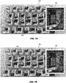
- FIGS. 7A and 7B show a service panel 700 located in a centrally located area accessible to the flight crew.
- the service panel 700 may be in a galley area assigned to a seating class.
- Each seating class e.g., first class, business class, coach class
- the service panel 700 includes a display such as a graphical user interface (GUI) configured to display a virtual floorplan 702 of the seating class.
- GUI graphical user interface
- the service panel 700 may be a touchscreen interface. Additional information may be displayed simultaneously with the floorplan 702 including user information, number of active service issues, service issue priority, suggested responsive actions, and other information.
- the virtual floorplan 702 displays the layout of passenger suites and real-time positions of the objects monitored for condition changes.
- An object in the process of a condition change, or an object having recently undergone a condition change may be highlighted on the virtual floorplan 702 to indicate to the flight crew the service issue and service issue location.
- FIG. 7A shows a suite door 704 undergoing a condition change (e.g., opening or closing) as a highlighted feature on the virtual floorplan 702 to alert the flight crew.
- FIG. 7B shows a tray table 706 undergoing or having recently undergone a condition change (e.g., stowed to deployed or vice versa) and the tray table highlighted on the virtual floorplan 700.
- the cabin service system may facilitate preparation for take-off and landing by alerting the flight crew to nonconforming issues and positions.
- the cabin service system may further utilize the networked sensors to detect objects unintentionally left behind during deplaning.
- the cabin service system may further utilize the networked sensors to provide an indication of when items are not operating properly and require repair or replacement.
Abstract
Description
- Air travelers, and particularly those traveling in premium seating classes, have needs that must be attended to by the flight crew. Passenger needs may include, for example, food, drink, privacy, sleep, comfort and technology requests, among others. In conventional airliners, flight crew actions are typically on-demand responsive to individual passenger requests. Requests may be initiated by passengers via verbal communications to the flight crew, service crew call buttons, etc. Such modes of communication have inherent delays in response times because of the ways in which requests are made and processed, the number of outstanding requests, flight crew member availability, flight crew interactions, etc.
- For example, a traveling passenger waking from a sleep may have an immediate need for a sitting position change, bedding removal, food or drink. In another example, a traveling passenger finished with a meal may have an immediate need for meal tray and trash removal. In conventional service systems, attention to these needs is provided by the flight crew in response to a passenger-initiated request. Requests must first be noticed by the flight crew before the flight crew can visit the passenger to determine the need before ultimately acting to address the need. Such processes and delays are undesirable to traveling passengers, and particularly those paying premium fares.
- To create a more premium travel experience, what is needed is a system that allows the flight crew to be proactive in addressing passengers needs as opposed to being reactive as in conventional cabin management systems.
- In one aspect, the present invention provides a according to claim 1. In some embodiments the processing system is configured to correlate using the table the condition changes of the objects with the predetermined service issues, retrieve from the table the actions to be completed by the service crew members corresponding to the predetermined service issues, and indicate through the device the actions to be completed by the service crew members responsive to the condition changes of the objects.
- In some embodiments, the system further comprises individual passenger suites positioned in the aircraft cabin environment, for example embodied as an aircraft passenger cabin environment, each of the passenger suites including an adjustable passenger seat, a suite door, and at least one suite amenity, wherein sensors include at least one first sensor operable for sensing a position change of the adjustable passenger seat, at least one second sensor operable for sensing a position change of the suite door, and at least one third sensor operable for sensing a condition change of the at least one suite amenity.
- In some embodiments, the device includes a display, wherein the received condition changes are visually displayed on the device, and wherein the actions to be completed by the service crew members are visually displayed on the device.
- In some embodiments, the device includes a display and the device is configured to visually display a virtual floorplan of the aircraft cabin environment including individual passenger suites, wherein the objects are associated with at least one of seats, furniture, amenities and passengers within or part of the individual passenger suites, and wherein condition changes of the objects are visually displayed on the virtual floorplan in real-time.
- In some embodiments, the device is a wall-mounted display positionable in a crew service area within the aircraft cabin environment.
- In some embodiments, the device is a handheld device including a display, a display positionable in a crew service area, or a wearable device.
- In some embodiments, the sensors include one or more of visual sensors, position sensors, and status sensors.
- In some embodiments, the processor is further configured to reconcile received condition changes of objects with predetermined time values associated with the predetermined service issues, such that time values exceeding predetermined time values cause the processor to indicate, through the device, the received condition changes of the objects, and time values less than the predetermined time values cause the processor not to indicate, through the device, the received condition changes of the objects.
- In some embodiments, the processor is further configured to confirm, through the device, that an action to be completed by the service crew members responsive to the condition changes of the objects has been completed, and record, in the memory of the computer, responsiveness criteria of the service crew members associated with the actions to be completed by the service crew members.
- In some embodiments, the processor is further configured to communicate with a passenger manifest including passenger preferences and modify the condition changes of the objects according to the passenger preferences.
- In some embodiments the system comprises a table stored in a memory of a computer including actions to be completed by service crew members responsive to the predetermined service issues and processing circuitry communicatively coupled to the memory.
- In some embodiments, the processing circuitry is further configured to correlate using a table the condition changes of the objects with the predetermined service issues, retrieve from the table actions to be completed by the service crew members responsive to the predetermined service issues, and indicate through the device the actions to be completed by the service crew members responsive to the condition changes of the objects.
- In some embodiments, the system further includes passenger suites positioned in the aircraft cabin environment, for example embodied as an aircraft passenger cabin environment, each of the passenger suites including an adjustable passenger seat, a suite door, and at least one suite amenity, wherein the sensors include at least one first sensor operable for sensing a position change of the adjustable passenger seat, at least one second sensor operable for sensing a position change of the suite door, and at least one third sensor operable for sensing a condition change of the at least one suite amenity.
- In some embodiments, the processor is further configured to reconcile received condition changes of objects with predetermined time values associated with the predetermined service issues, such that time values exceeding predetermined time values cause the processor to indicate, through the device, the received condition changes of the objects, and time values less than the predetermined time values cause the processor not to indicate, through the device, the received condition changes of the objects.
- In some embodiments, the processor if further configured to at least one of confirm through the device that an action to be completed by the service crew members responsive to the condition changes of the objects has been completed, record responsiveness criteria of the service crew members associated with the actions to be completed by the service crew members, and communicate with a passenger manifest including passenger preferences and modify the condition changes of the objects according to the passenger preferences.
- Embodiments of the present invention can include one or more or any combination of the above aspects, features, and configurations.
- The present invention may be better understood when consideration is given to the following detailed description thereof. Such description makes reference to the included drawings, which are not necessarily to scale, and in which some features may be exaggerated and some features may be omitted or may be represented schematically in the interest of clarity. Like reference numerals in the drawings may represent and refer to the same or similar element, feature, or function. In the drawings:
-
FIG. 1 is a block diagram illustrating a first configuration of a predictive cabin service system according to the present invention; -
FIG. 2 is a block diagram illustrating a second configuration of a predictive cabin service system according to the present invention; -
FIG. 3 is a block diagram illustrating a feedback loop associated with the predictive cabin service system embodiments according to the present invention; -
FIG. 4 illustrates sensor networks configured to sense condition changes associated with aspects of individual passenger suites in an aircraft passenger cabin environment; -
FIGS. 5A and 5B illustrate sensor networks configured to sense condition changes associated with passenger seats, suite doors and the environment of passenger suites in an aircraft passenger cabin environment; -
FIGS. 6A and 6B illustrate sensor networks configured to sense position changes associated with a tray table in an aircraft passenger suite; and -
FIGS. 7A and 7B illustrate a virtual floorplan of an aircraft passenger cabin environment displaying respective condition changes associated with a suite door and tray table on a centrally located cabin display panel and a member of the flight crew interacting with the same. - The present invention is described hereinafter with reference to the accompanying drawings in which exemplary embodiments are shown. However, the present invention may be embodied in many different forms and should not be construed as limited to the representative embodiments set forth herein.
- Disclosed herein are coordinated and networked systems and methods utilizing various sensor types, networks, interpretive processes and visual capture methods to analyze and predict the immediate future needs of passengers. Immediate future needs may be, for example, predicted needs associated with a condition change such as a passenger, object, environment or activity change. Immediate future needs may be correlated with predetermined flight crew actions responsive to the condition changes within the passenger cabin environment. Data within the networked system may be streamed from sensors and sensor networks positioned in the aircraft cabin environment, for example, within or in proximity to seats, suites, lavatories, furniture and other objects. Sensors may monitor object movements such as position and geometry changes and may communicate with other sensors in the system such as those associated with seat actuation or other strategically positioned sensors. Sensing may also include streaming passenger location positioning using image processing and a sensor or an array of sensors.
-
FIG. 1 depicts a first configuration of a predictive cabin service system generally atreference numeral 100. Aboard an aircraft,sensors 102 of one or more sensor networks are positioned within the aircraft cabin environment. For example, sensor networks may be positioned in relation to and associated with one or more of passenger seats, passenger suites, lavatories, overhead stowage bins, closets, amenities, furniture, electronic equipment, etc. Sensor networks may also be positioned in relation to predetermined areas to be monitored within the passenger cabin environment. Each sensor, sensor array or sensor network is configured to sense a condition change within the aircraft cabin environment. Condition changes may include, but are not limited to, object movements, passenger movements, environmental changes, activity changes, equipment changes, etc. Each condition change to be monitored determines the type(s) of sensor, sensor array and sensor network required. - Sensors utilized in the systems according to the present invention may include, but are not limited to, acoustic sensors, chemical sensors, electrical sensors, environmental sensors, position sensors, optical sensors, pressure sensors, force sensors, temperature sensors, and proximity sensors. Acoustic sensors may be utilized to detect noise levels in a predetermined area of the aircraft cabin environment, such as within an individual passenger suite, for device control, comfort, privacy, etc. Chemical sensors may be utilized to monitor the environment. Electrical sensors may be utilized to detect electrical equipment status or mode changes, or may be electrically coupled with seat control systems to monitor condition changes corresponding to technology needs, comfort, etc. Environmental sensors may be utilized to monitor discrete sections of the aircraft cabin environment and may be coordinated with other local sensor systems. Temperature sensors may be utilized to predict passenger comfort needs. The remaining sensor types may be utilized, for example, to detect position and geometry changes in the aircraft cabin environment to predict all types of passenger needs.
- A variety of sensors may be mounted onto or within objects to monitor position. For example, a gyroscopic sensor or gyro sensor may be used to identify the orientation of an object including the sensor. An orientation sensor provides information regarding position in comparison to a reference plane. Examples of orientation sensors include rotary encoders and inclinometers. A Hall effect sensor may be used to determine proximity to a magnetic field, which can be translated to a range of positions. Other proximity sensors include optical, capacitive, and inductive proximity sensors. In a simpler embodiment, a reed switch is opened or closed by a magnetic field, such that a binary position (e.g., in this orientation, not in this orientation) may be readily determined based upon a switch position. In another simple embodiment, an optical switch may be used to determine whether a beam of light has been broken, which can translate to whether a certain object is in a particular position or not.
- As shown in
FIG. 1 , sensors utilized in the exemplary system shown may include sensors of the above types such asvisual sensors 104,position sensors 106, andstatus sensors 108. Each sensor may be a device or a subsystem capable of detecting condition changes within the aircraft cabin environment and communicating with aprocessor 110. For example,visual sensors 104 may detect objects and/or passengers to detect presence or absence and to track movements.Position sensors 106 may detect positional or geometry changes of objects.Status sensors 108 may detect operational modes or status of devices. - The
system sensors 102 relay information to thesystem processor 110 where processing logic analyzes the data received to confirm service issues corresponding to predictive actions. Theprocessor 110 may be a component of a server, such as a digital computer also including input/output (I/O) interfaces, a network interface, a data store, and memory. The components may be communicatively coupled via a local interface such as one or more buses or other wired or wireless connections. The local interface may have additional elements such as controllers, buffers (caches), drivers, repeaters, and receivers, among others, to enable communications. Further, the local interface may include address, control, and/or data connections to enable appropriate communications among the components. - The
processor 110 is a hardware device for executing software instructions such as collation algorithms. Theprocessor 110 may be any custom made or commercially available processor, a central processing unit (CPU), an auxiliary processor among several processors associated with the server, a semiconductor-based microprocessor (in the form of a microchip or chip set), or generally any device for executing software instructions. When the server is in operation, the processor is configured to execute software stored within the memory, to communicate data to and from the memory, and to generally control operations of the server pursuant to the software instructions. The I/O interfaces may be used to receive user input from and/or for providing system output to one or more devices or components such as thesensors 102, anaircraft network 112, andflight crew devices 114. I/O interfaces may include a serial port, a parallel port, a small computer system interface (SCSI), a serial ATA (SATA), a fibre channel, Infiniband, iSCSI, a PCI Express interface (PCI-x), an infrared (IR) interface, a radio frequency (RF) interface, and/or a universal serial bus (USB) interface. - The network interface may be used to enable the server to communicate on a network, such as the Internet, a wide area network (WAN), a local area network (LAN) such as the
secure aircraft network 112, and the like, etc. The network interface may include address, control, and/or data connections to enable appropriate communications on the network. A data store may be used to store data. The data store may include any of volatile memory elements (e.g., random access memory (RAM, such as DRAM, SRAM, SDRAM, and the like)), nonvolatile memory elements (e.g., ROM, hard drive, tape, CDROM, and the like), and combinations thereof. Moreover, the data store may incorporate electronic, magnetic, optical, and/or other types of storage media. In one example, the data store may be located internal to the server such as, for example, an internal hard drive connected to the local interface in the server. Additionally, in another embodiment, the data store may be located external to the server such as, for example, an external hard drive connected to the I/O interfaces (e.g., SCSI or USB connection). In a further embodiment, the data store may be connected to the server through a network, such as, for example, a network attached file server. - The memory may include any of volatile memory elements (e.g., random access memory (RAM, such as DRAM, SRAM, SDRAM, etc.)), nonvolatile memory elements (e.g., ROM, hard drive, tape, CDROM, etc.), and combinations thereof. Moreover, the memory may incorporate electronic, magnetic, optical, and/or other types of storage media. The software in memory may include one or more software programs, each of which includes an ordered listing of executable instructions for implementing logical functions. The software in the memory includes a suitable operating system (O/S) and one or more programs. The operating system essentially controls the execution of other computer programs, such as the one or more programs, and provides scheduling, input-output control, file and data management, memory management, and communication control and related services. The one or more programs may be configured to implement the various processes, algorithms, methods, techniques, etc. described herein.
- The
flight crew devices 114 may be digital devices that, in terms of hardware architecture, include a processor, input/output (I/O) interfaces, a data store, a memory and a display. For example, theflight crew devices 114 may include one or more of mobilehandheld devices 116, centrally locatedcabin display devices 118,wearable devices 120, and in-ear or other body mounteddevices 122. The active system may include one or more of these device types to ensure that the flight crew is made aware of, by redundant communications to the various devices, indicated service issues in a timely manner to minimize response time delays. Mobile flight crew devices may be enabled for wireless communication to an external access device or network. The data store may be used to store data. The memory may include any of volatile memory elements, nonvolatile memory elements, and combinations thereof. Programs can include an application or "app" which provides various functionality. - Upon activation of the
system 100, and with at least onesensor 102 in an active sensing mode, condition changes are monitored and information conveyed to theprocessor 110. The main routine of theprocessor 110 operates to receive and analyze the condition changes to determine the occurrence of a qualifying condition change corresponding to a predetermined service issue. Predetermined service issues are correlated to actions to be considered or performed on the part of the flight crew to attend to a potential passenger need. Theprocessor 110 may communicate with a look-up table stored in the sever memory containing the list of qualifying condition changes and responsive actions. Upon confirmation of a qualifying service issue, the processor operates to send an instruction to one or more of theflight crew devices 116 to cause the one or more devices to display at least one of the condition change, service issue, and predetermined flight crew actions responsive to the service issue. - Flight crew actions are actions to be considered, and more likely actions to be performed by the flight crew responsive to an indicated service issue. Flight crew actions may be stored on the look-up table corresponding to the service issues and condition changes. In some embodiments, the flight crew actions are pre-programmed and predetermined. In some embodiments, the flight crew may have the ability to modify the flight crew actions, through the
flight crew devices 116 or another avenue, based on passenger preferences and historical data. For example, a passenger may desire a specific flight crew action, different from the preprogrammed action(s), responsive to a particular service issue. In the case of preferences, modifications can be made or notes can be added to the look-up table specific for that traveling passenger in embodiments in which the look-up table is modifiable. Modifications may be stored in memory and tagged or otherwise associated with passenger information by way of name, frequent flyer number or other passenger identifier, to better serve a passenger for the remainder of the flight and on future flights. -
FIG. 2 depicts a second configuration of a predictive cabin service system generally atreference numeral 200. Like thefirst system 100, thesecond system 200 includessensors 102, aprocessor 210, asecure aircraft network 112, and one or moreflight crew devices 114. Thesecond system 200 further includes information or access to one or more offrequent flyer information 202, social media andtravel data 204, and previoushistorical data 206 such as flight crew notations and modifications. The processing logic is further configured to access one or more of the additional information sources to potentially modify the indication or the flight crew action(s). In some embodiments, a passenger manifest may be used to update the look-up table with passenger preferences to modify one or more of the indications and flight crew actions. For example, while one passenger may typically desire food or beverage attention immediately after waking from a sleep, a different passenger may prefer not to be disturbed for a predetermined period of time after waking. While a default setting may be a flight crew action to attend to a passenger within a short time period, a preference setting may be used to set or indicate a delay to a flight crew action. The external information sources including thefrequent flyer information 202,social media information 204, and previoushistorical data 206 may be factors for correlating or modifying flight crew actions. In some embodiments, the system may be configured with a form fillable by passengers to set specific preferences, wherein the processing logic is configured to process the forms and update indications or actions based on the passenger preferences. -
FIG. 3 depicts afeedback loop sub-routine 300 executable by the processor (110, 210). In the sub-routine 300, the flight crew and/or the passengers may interact, manually or automatically, with the system (100, 200) to provide feedback to the airline. Feedback may include responsive to indications, response times, passenger satisfaction, etc. The feedback loop sub-routine may be a component of the system (100, 200) executable by the processor, or may a separate sub-system. In some embodiments, the flight crew may be tasked with entering or confirming a response to an indicated service issue via one of theflight crew devices 114, such that response time and response action can be measured, gauged and reported for quality control or other purposes. In some embodiments, the system may be remotely accessed by passengers post-flight for passenger feedback for quality control. - In a passenger suite or like environment according to the present invention, there may be several systems and subsystems utilized to create a premium travel experience. For example, each seat itself may include an articulating sitting mechanism that supports a cushioned seat bottom, backrest, leg rest and headrest. Embedded in this adjustable mechanism may be touch interfaces, motors and actuators that move the overall seat from sitting to bed through intermediate lounge positions. Such mechanisms may utilize sensors in connection with power, position, orientation and status. Other systems and subsystems may be utilized in surrounding furniture and stowage. For example, doors, tray tables and various stowages may move or have moving components such as lids and doors. Sensor systems and subsystems may be embedded in these mechanical objects for wired or wireless communication with the system. Electronic equipment such as in-flight entertainment equipment (IFE) may also be equipped with sensors and incorporate software that reacts to inputs. Not limited to seats, furniture, mechanical objects, electronics and the immediate surrounding environment, there may be other areas within the aircraft passenger cabin environment in which the predictive cabin service system operates to sense condition changes to alert the flight crew to attend to a service issue.
- In a first exemplary implementation of the systems according to the present invention,
FIG. 4 depicts a portion of an aircraftpassenger cabin environment 400 including a layout ofindividual passenger suites passenger suite more privacy walls 404. Eachpassenger suite entrance 406 formed by a break in theprivacy walls 404 or between spaced privacy walls of longitudinally adjacent suites. Theentrance 406 can be opened or closed utilizing amoveable door 408 such as a sliding door configured to slide along rails. As shown inFIG 4 , thedoor 408 of theforward suite 402A is shown open allowing access into the forward suite, while thedoor 408 of theaft suite 402B is shown closed blocking access into the aft suite. Each suite further includes an adjustable seat and amenities positioned within the suite interior. - Networked sensors are embedded in one or more of the seat, seat surrounds, and in adjacent locations to sense condition changes such as position changes and passenger movements. In some embodiments, a first subset of sensors includes position sensors configured to sense condition changes including door movements. Each
individual suite sensor 410 may be located on thedoor 408 and a counterpart sensor may be located on a surround or stationary privacy wall. The sensors may be contact or non-contact sensors and a position change of one sensor relative to the other in a first direction may indicate door closing movement, while a position change of one sensor relative to the other in a second direction opposite the first direction may indicate door opening movement. Other sensor arrangements including single sensors such as proximity sensor may be utilized. The aircraftpassenger cabin environment 400 may further include a second subset ofsensors 412 configured to sense seat or passenger movement. The sensors of the second subset ofsensors 412 may include, for example, infra-red, video or like sensors for visual capture of objects. In one embodiment, door opening movement may trigger a sensor of the first subset, and the seat moving to an upright sitting position may trigger a sensor of the second subset, and the system may coordinate sensor outputs from the two subset to indicate a service issue to the flight crew. - The aircraft
passenger cabin environment 400 may further include a third subset ofsensors 414 located in the ceiling above thepassenger suites sensor 414 may be configured to monitor the suite, a specific object within the suite, the passenger, or the suite environment utilizing one or more of position, vision, chemical and environmental sensors. - In another exemplary implementation of the systems according to the present invention,
FIGS. 5A and 5B depict a portion of an aircraftpassenger cabin environment 500 including a layout ofindividual passenger suites sensors 504 may be positioned to sense condition changes of thesuite doors 506 such as door opening and closing, which may be condition changes indicating predetermined service issues linked with responsive actions to be completed by the flight crew. The first subset ofsensors 504 may also be used to indicate door position and latching to comply with TTOL requirements. A second subset ofsensors 508 may be located in the ceiling and may include one or more of environmental, chemical and visual sensors configured to monitor one or more of passenger movements, object movements, environmental conditions, etc. A third subset of sensors is configured to monitor positional information associated with the passenger seats 510 to sense sitting position condition changes. The sensors may operate on their own or may communicate with strategically positioned sensors such as those associated with the seat actuators. A change in sitting position from lie-flat as shown inFIG. 5A to upright sitting as shown inFIG. 5B is a condition change indicating that a passenger that was asleep is now awake and thus may have a need to be attended to. The condition change is indicated to the flight crew through one of the flight crew devices to identify the service issue such that responsive action can be taken. - The processing logic may coordinate the various sensor subsystems within the aircraft cabin environment. In some embodiments, the collation algorithm may gather the condition change information from one or more subsystems and compare that information against predetermined criteria such as time intervals. For example, a seat condition change from lie-flat to upright after a predetermined time interval has passed may likely indicate that a sleeping passenger has awoken so the flight crew can anticipate a service need of the waking passenger such as food, drink, bedding removal, etc. In comparison, a seat condition change from lie-flat to upright before a predetermined time interval has passed may indicate a passenger attempted to sleep but could not and therefore a different service need from the flight crew such as more comfort. Sensor subsystems may be networked. For example, condition changes associated with a suite door closing, the seat moved from lounge to bed, and the in-flight entertainment system (IFE) darkened or turned off may be collected, analyzed and compared to determine a passenger is preparing to sleep such that the system can alert the flight crew to the same.
- In another exemplary implementation of the systems according to the present invention,
FIGS. 6A and 6B depict a portion of the interior of an individualaircraft passenger suite 600. Eachpassenger suite 600 generally includes anadjustable passenger seat 602, avideo monitor 604 positioned forward of theseat 602, and a tray table 606 deployable from beneath thevideo monitor 604. Theseat 602 may transition to meet anottoman 608 located in afootwell 610 below the tray table 606 to increase the bed length. A first sensor network senses condition changes associated with the tray table 606, and specifically, positional changes of the tray table. The positional changes may correspond to tray table movements, in this case lateral movements toward or away from theseat 602 which correspond to deployment or stowage directions of the tray table. For example, a passenger may actuate movement of the tray table 606 toward themselves to indicate their desire to dine or use the table for another purpose and may actuate movement of the tray table 606 away from themselves to indicate they are finished dining and desire dinnerware and trash removal. In some embodiments, the system may be configured to show the position of the tray table 606 at movement direction in real-time to alert the flight crew for anticipatory services. In some embodiments, avisual sensor 612 may be located within the suite proximate the seat to sense passenger actions corresponding to sensed condition changes. To satisfy privacy concerns, the sensor may not capture and record video. - Upon collection and analyzation of the sensed condition changes, the processing logic causes the processor to send instructions to one or more of the flight crew devices to alert the flight crew of service issues. Alerts may be in the form of visual alerts, audio alerts and combinations thereof. Alerts may highlight a condition change associated with an object essentially in real-time. Alerts may be accompanied by suggested flight crew actions responsive to the particular service issue(s). In some embodiments, alerts may require a response from the flight to confirm receipt of the alert.
- In an exemplary implementation of the system,
FIGS. 7A and 7B show aservice panel 700 located in a centrally located area accessible to the flight crew. For example, theservice panel 700 may be in a galley area assigned to a seating class. Each seating class (e.g., first class, business class, coach class) may include its own service panel for flight crew usage. As shown, theservice panel 700 includes a display such as a graphical user interface (GUI) configured to display avirtual floorplan 702 of the seating class. Theservice panel 700 may be a touchscreen interface. Additional information may be displayed simultaneously with thefloorplan 702 including user information, number of active service issues, service issue priority, suggested responsive actions, and other information. - The
virtual floorplan 702 displays the layout of passenger suites and real-time positions of the objects monitored for condition changes. An object in the process of a condition change, or an object having recently undergone a condition change, may be highlighted on thevirtual floorplan 702 to indicate to the flight crew the service issue and service issue location. For example,FIG. 7A shows asuite door 704 undergoing a condition change (e.g., opening or closing) as a highlighted feature on thevirtual floorplan 702 to alert the flight crew.FIG. 7B shows a tray table 706 undergoing or having recently undergone a condition change (e.g., stowed to deployed or vice versa) and the tray table highlighted on thevirtual floorplan 700. - In addition to predicting and attending to passenger needs, the cabin service system according to the present invention may facilitate preparation for take-off and landing by alerting the flight crew to nonconforming issues and positions. The cabin service system may further utilize the networked sensors to detect objects unintentionally left behind during deplaning. The cabin service system may further utilize the networked sensors to provide an indication of when items are not operating properly and require repair or replacement.
- The foregoing description provides embodiments of the invention by way of example only. It is envisioned that other embodiments that are within the scope of the present invention may perform similar functions and/or achieve similar results
Claims (11)
- A system (100, 200) for monitoring passenger activity in an aircraft cabin environment (400, 500), the system (100, 200) comprising:sensors (102, 104, 106, 108, 410, 412, 412, 504, 508, 612) positionable within an aircraft cabin environment (400, 500) configured to detect condition changes of objects positioned in the aircraft cabin environment (400, 500), the condition changes corresponding to predetermined service issues predictive of immediate future passenger needs;a device (114, 116, 118, 120, 122) configured to indicate detected condition changes of the objects; andprocessing circuitry communicatively coupled to the sensors (102, 104, 106, 108, 410, 412, 412, 504, 508, 612) and the device (114, 116, 118, 120, 122), the processing circuitry configured to execute a plurality of machine-readable instructions stored in a non-transitory computer readable medium in a computer, wherein the instructions, when executed by the processing circuitry, cause the processing circuitry to:receive, from the sensors (102, 104, 106, 108, 410, 412, 412, 504, 508, 612), signals indicating condition changes of the objects; andindicate, through the device (114, 116, 118, 120, 122), the received condition changes of the objects.
- The system (100, 200) according to claim 1, further comprising a table stored in a memory of a computer, the table including actions to be completed by service crew members responsive to the predetermined service issues and comprising processing circuitry communicatively coupled to the memory.
- The system (100, 200) according to claim 1 or 2, wherein the processing circuitry is further configured to:correlate, using a table, the condition changes of the objects with the predetermined service issues;retrieve, from the table, actions to be completed by the service crew members corresponding or responsive to the predetermined service issues; and indicate, through the device (114, 116, 118, 120, 122), the actions to be completed by the service crew members responsive to the condition changes of the objects.
- The system (100, 200) according to one or more of the preceding claims, further comprising passenger suites (402A, 402B, 502A, 502B, 600) positioned in the aircraft cabin environment (400, 500), each of the passenger suites (402A, 402B, 502A, 502B, 600) including an adjustable passenger seat (510, 602), a suite door (408, 506), and at least one suite amenity, wherein the sensors (102, 104, 106, 108, 410, 412, 412, 504, 508, 612) include at least one first sensor (412, 612) operable for sensing a position change of the adjustable passenger seat (510, 602), at least one second sensor (410, 504) operable for sensing a position change of the suite door (408, 506), and at least one third sensor (414, 508) operable for sensing a condition change of the at least one suite amenity.
- The system (100, 200) according to one or more of the preceding claims, wherein the device (114, 116, 118, 120, 122) includes a display, wherein the received condition changes are visually displayed on the device (114, 116, 118, 120, 122), and wherein the actions to be completed by the service crew members are visually displayed on the device (114, 116, 118, 120, 122).
- The system (100, 200) according one or more of the preceding claims, wherein the device includes a display and the device (114, 116, 118, 120, 122) is configured to visually display a virtual floorplan (702) of the aircraft cabin environment (400, 500) including individual passenger suites (402A, 402B, 502A, 502B, 600), wherein the objects are associated with at least one of seats, furniture, amenities and passengers within or part of the individual passenger suites (402A, 402B, 502A, 502B, 600), and wherein condition changes of the objects are visually displayed on the virtual floorplan (400, 500) in real-time.
- The system (100, 200) according to claim 5 or 6, wherein the device (114) is a wall-mounted display (118) positionable in a crew service area within the aircraft cabin environment (400, 500).
- The system (100, 200) according to one or more of the preceding claims, wherein the device (114) is a handheld device (116) including a display, a display positionable in a crew service area (118), or a wearable device (120, 122).
- The system (100, 200) according to one or more of the preceding claims, wherein the sensors (102, 104, 106, 108, 410, 412, 412, 504, 508, 612) include one or more of visual sensors (104), position sensors (106), and status sensors (108).
- The system (100, 200) according to one or more of the preceding claims, wherein the processor (110, 210) is further configured to reconcile received condition changes of objects with predetermined time values associated with the predetermined service issues, such that time values exceeding predetermined time values cause the processor (110, 210) to indicate, through the device (114, 116, 118, 120, 122), the received condition changes of the objects, and time values less than the predetermined time values cause the processor (110, 210) not to indicate, through the device (114, 116, 118, 120, 122), the received condition changes of the objects.
- The system according to one or more of the preceding claims, wherein the processor (110, 210) is further configured to at least one of:confirm, through the device (114, 116, 118, 120, 122), that an action to be completed by the service crew members responsive to the condition changes of the objects has been completed;record, preferably in the memory of the computer, responsiveness criteria of the service crew members associated with the actions to be completed by the service crew members; andcommunicate with a passenger manifest including passenger preferences and modify the condition changes of the objects according to the passenger preferences.
Applications Claiming Priority (1)
| Application Number | Priority Date | Filing Date | Title |
|---|---|---|---|
| US16/526,495 US11203433B2 (en) | 2019-07-30 | 2019-07-30 | Predictive aircraft passenger cabin service system and method |
Publications (1)
| Publication Number | Publication Date |
|---|---|
| EP3771648A1 true EP3771648A1 (en) | 2021-02-03 |
Family
ID=68916359
Family Applications (1)
| Application Number | Title | Priority Date | Filing Date |
|---|---|---|---|
| EP19215958.0A Pending EP3771648A1 (en) | 2019-07-30 | 2019-12-13 | Predictive aircraft passenger cabin service system and method |
Country Status (3)
| Country | Link |
|---|---|
| US (1) | US11203433B2 (en) |
| EP (1) | EP3771648A1 (en) |
| CN (1) | CN112308359A (en) |
Cited By (1)
| Publication number | Priority date | Publication date | Assignee | Title |
|---|---|---|---|---|
| CN117408437A (en) * | 2023-12-01 | 2024-01-16 | 珠海翔翼航空技术有限公司 | Civil aviation cabin service method, system and equipment |
Families Citing this family (1)
| Publication number | Priority date | Publication date | Assignee | Title |
|---|---|---|---|---|
| WO2018164710A1 (en) * | 2017-03-06 | 2018-09-13 | Zodiac Seats Us Llc | Boarding guidance system |
Citations (3)
| Publication number | Priority date | Publication date | Assignee | Title |
|---|---|---|---|---|
| US20170283086A1 (en) * | 2016-04-04 | 2017-10-05 | B/E Aerospace, Inc. | Aircraft Passenger Activity Monitoring |
| US20180181919A1 (en) * | 2014-03-24 | 2018-06-28 | Daniel JOBLING | Travel Environment Control |
| US10237511B2 (en) * | 2016-04-01 | 2019-03-19 | B/E Aerospace, Inc. | Projection information display |
Family Cites Families (8)
| Publication number | Priority date | Publication date | Assignee | Title |
|---|---|---|---|---|
| US7878586B2 (en) * | 2007-10-29 | 2011-02-01 | The Boeing Company | System and method for an anticipatory passenger cabin |
| WO2011082998A1 (en) * | 2009-12-15 | 2011-07-14 | Airbus Operations Gmbh | Supply module for passenger transport vehicles |
| US9742898B2 (en) * | 2015-08-31 | 2017-08-22 | The Boeing Company | Mobile cabin panel |
| CN113287958A (en) * | 2015-10-30 | 2021-08-24 | 金伯利-克拉克环球有限公司 | Product use acoustic determination system |
| DE102016012912B4 (en) * | 2016-10-29 | 2022-06-15 | Diehl Aerospace Gmbh | Monitoring module for a seat in a passenger aircraft, monitoring device and passenger aircraft |
| US11597519B2 (en) | 2017-10-17 | 2023-03-07 | The Boeing Company | Artificially intelligent flight crew systems and methods |
| US10775793B2 (en) * | 2017-12-22 | 2020-09-15 | The Boeing Company | Systems and methods for in-flight crew assistance |
| US20190391581A1 (en) * | 2018-06-26 | 2019-12-26 | Uber Technologies, Inc. | Passenger Health Monitoring and Intervention for Autonomous Vehicles |
-
2019
- 2019-07-30 US US16/526,495 patent/US11203433B2/en active Active
- 2019-12-12 CN CN201911272315.0A patent/CN112308359A/en active Pending
- 2019-12-13 EP EP19215958.0A patent/EP3771648A1/en active Pending
Patent Citations (3)
| Publication number | Priority date | Publication date | Assignee | Title |
|---|---|---|---|---|
| US20180181919A1 (en) * | 2014-03-24 | 2018-06-28 | Daniel JOBLING | Travel Environment Control |
| US10237511B2 (en) * | 2016-04-01 | 2019-03-19 | B/E Aerospace, Inc. | Projection information display |
| US20170283086A1 (en) * | 2016-04-04 | 2017-10-05 | B/E Aerospace, Inc. | Aircraft Passenger Activity Monitoring |
Cited By (2)
| Publication number | Priority date | Publication date | Assignee | Title |
|---|---|---|---|---|
| CN117408437A (en) * | 2023-12-01 | 2024-01-16 | 珠海翔翼航空技术有限公司 | Civil aviation cabin service method, system and equipment |
| CN117408437B (en) * | 2023-12-01 | 2024-03-29 | 珠海翔翼航空技术有限公司 | Civil aviation cabin service method, system and equipment |
Also Published As
| Publication number | Publication date |
|---|---|
| US20210031924A1 (en) | 2021-02-04 |
| CN112308359A (en) | 2021-02-02 |
| US11203433B2 (en) | 2021-12-21 |
Similar Documents
| Publication | Publication Date | Title |
|---|---|---|
| US20110068227A1 (en) | System and method for an anticipatory passenger cabin | |
| EP3372503B1 (en) | Touch-free operable stowage bin assemblies | |
| EP3439959B1 (en) | Aircraft passenger activity monitoring | |
| EP3372502A1 (en) | Vehicles including electronic stowage bin control systems | |
| CA2996558C (en) | Vehicle stowage bin assemblies having weight sensors | |
| US11203433B2 (en) | Predictive aircraft passenger cabin service system and method | |
| BR102018004700B1 (en) | SYSTEMS AND CONTROL METHODS FOR ELECTRONIC, VEHICLE AND AIRCRAFT STORAGE COMPARTMENTS | |
| US9205914B1 (en) | Distributed architecture for a system and a method of operation of the system incorporating a graphical user interface controlling functions in a vehicle cabin | |
| US20170210484A1 (en) | Virtual Aircraft Operations Checklist | |
| US20190112050A1 (en) | Artificially intelligent flight crew systems and methods | |
| WO2013187985A1 (en) | Aircraft passenger health management | |
| US20220055751A1 (en) | Integrated aircraft seat control panel | |
| US20180308037A1 (en) | Vehicle attendant task management systems and methods | |
| US10773806B2 (en) | Seat actuation control through in-flight entertainment system | |
| US20150314875A1 (en) | Digital crew assist | |
| CN113135294B (en) | Contoured passenger seat privacy shell shape for aircraft cabin kit | |
| JP6122601B2 (en) | Self-configuring cabin management system | |
| US20210276714A1 (en) | Overhead stowage bin with electronic control system | |
| US11572173B2 (en) | Aircraft cabin system control by gestures within task envelopes | |
| US20230335138A1 (en) | Onboard aircraft system with artificial human interface to assist passengers and/or crew members | |
| CA3042662A1 (en) | System and method of determining a seat back status of a passenger seat in a vehicle | |
| US11024285B2 (en) | Noise-reduction in aircraft | |
| EP3929083A2 (en) | Aircraft smart cabin control | |
| EP3380917A1 (en) | System and a method of operation of the system incorporating a graphical user interface in a bulkhead of a vehicle cabin | |
| CN115333229A (en) | System and method for managing and predicting power usage of ultraviolet lamps within an environment |
Legal Events
| Date | Code | Title | Description |
|---|---|---|---|
| PUAI | Public reference made under article 153(3) epc to a published international application that has entered the european phase |
Free format text: ORIGINAL CODE: 0009012 |
|
| STAA | Information on the status of an ep patent application or granted ep patent |
Free format text: STATUS: THE APPLICATION HAS BEEN PUBLISHED |
|
| AK | Designated contracting states |
Kind code of ref document: A1 Designated state(s): AL AT BE BG CH CY CZ DE DK EE ES FI FR GB GR HR HU IE IS IT LI LT LU LV MC MK MT NL NO PL PT RO RS SE SI SK SM TR |
|
| AX | Request for extension of the european patent |
Extension state: BA ME |
|
| RAP3 | Party data changed (applicant data changed or rights of an application transferred) |
Owner name: B/E AEROSPACE, INC. |
|
| STAA | Information on the status of an ep patent application or granted ep patent |
Free format text: STATUS: REQUEST FOR EXAMINATION WAS MADE |
|
| 17P | Request for examination filed |
Effective date: 20210803 |
|
| RBV | Designated contracting states (corrected) |
Designated state(s): AL AT BE BG CH CY CZ DE DK EE ES FI FR GB GR HR HU IE IS IT LI LT LU LV MC MK MT NL NO PL PT RO RS SE SI SK SM TR |
|
| STAA | Information on the status of an ep patent application or granted ep patent |
Free format text: STATUS: EXAMINATION IS IN PROGRESS |
|
| 17Q | First examination report despatched |
Effective date: 20220726 |
|
| P01 | Opt-out of the competence of the unified patent court (upc) registered |
Effective date: 20230608 |