EP3771607A1 - Retractable step system for getting into and out of a vehicle, and vehicle door assembly provided with such a system - Google Patents
Retractable step system for getting into and out of a vehicle, and vehicle door assembly provided with such a system Download PDFInfo
- Publication number
- EP3771607A1 EP3771607A1 EP20188440.0A EP20188440A EP3771607A1 EP 3771607 A1 EP3771607 A1 EP 3771607A1 EP 20188440 A EP20188440 A EP 20188440A EP 3771607 A1 EP3771607 A1 EP 3771607A1
- Authority
- EP
- European Patent Office
- Prior art keywords
- control member
- supporting element
- door
- shoulder
- along
- Prior art date
- Legal status (The legal status is an assumption and is not a legal conclusion. Google has not performed a legal analysis and makes no representation as to the accuracy of the status listed.)
- Granted
Links
Images


Classifications
-
- B—PERFORMING OPERATIONS; TRANSPORTING
- B61—RAILWAYS
- B61D—BODY DETAILS OR KINDS OF RAILWAY VEHICLES
- B61D23/00—Construction of steps for railway vehicles
- B61D23/02—Folding steps for railway vehicles, e.g. hand or mechanically actuated
-
- B—PERFORMING OPERATIONS; TRANSPORTING
- B60—VEHICLES IN GENERAL
- B60R—VEHICLES, VEHICLE FITTINGS, OR VEHICLE PARTS, NOT OTHERWISE PROVIDED FOR
- B60R3/00—Arrangements of steps or ladders facilitating access to or on the vehicle, e.g. running-boards
- B60R3/02—Retractable steps or ladders, e.g. movable under shock
Definitions
- a retractable step system for getting into and out of a vehicle according to claim 1.
- the leaf 12 in the opening position, is preferably arranged behind the upright 8 and is parallel to the side wall 6; the movement of the leaf 12 between the opening position and the closing position comprises a translation component along a horizontal direction 14, which is parallel to the side wall 6.
- the system 1 comprises an attachment structure 20, which is fixed to the structure 9 and carries, in a fixed position, a guide 21.
- the system 1 further comprises a supporting element, which, in the embodiment shown herein, is defined by a vertical bar 22, which is coupled to the guide 21 so as to vertically slide between a raised rest position ( figure 2 ), corresponding to the retracted position, and a lowered operating position ( figure 4 ), corresponding to the extended configuration.
- the bar 22 basically moves downward along the guide 21 because of the weight.
- the bar 22 comprises an upper portion 23, which, in the raised position, is housed in a compartment 24 ( figure 1 ) arranged between the lining 10 and the surface 11.
- the upper portion 23 preferably carries an appendage 25, which projects through the lining 10, i.e. outside of the compartment 24, so that it can manually be operated by a user in order to lift the bar 22 along the guide 21.
- the system 1 further comprises a step 26, which is coupled to a lower end 27 of the bar 22 in a movable manner between a vertical rest position ( figure 2 ), corresponding to the retracted configuration, and a horizontal support position ( figure 4 ), corresponding to the extended configuration.
- the step 26 comprises a footboard or support portion 28, which, in the horizontal position, projects from the bar 22 along a horizontal axis 29 ( figure 4 ), which is parallel to the direction 14, so as to allow a foot to be placed on it.
- the step 26 is preferably hinged to the end 27 about a hinge axis, which is orthogonal to the axis 29.
- the footboard 28 faces upward and horizontally faces the bar 22.
- the system 1 further comprises a control member 30, which is movable in response to a manual action of a user, and a stop device 31, which is active and vertically holds the bar 22 in the raised position when the member 30 is arranged in a first position (represented with a broken line in figure 2 , where the horizontal distance from the bar 22 is shown out of scale for clarity reasons).
- the stop device 31 is inactive and allows the bar 22 to freely move in a vertical manner between the raised position and the lowered position when the member 30 is arranged in a second position (shown in figures 3 and 4 ), which is distinct from the first one.
- the member 30 in order to shift from the first to the second position and vice versa, the member 30 is manually rotated about a rotation axis 34, which is parallel to the axis 29, for example through a 90° rotation.
- the member 30 comprises an end portion 35, which preferably is part of the plate 32 and, in the second position, projects toward the inside of the car 2 along a horizontal axis 37 orthogonal to the axes 29 and 34 (relative to the bar 22 and in the place that was occupied by the member 30 in the first position).
- the end portion 35 projects past the upright 8 ( figure 4 ) to as to intercept the path of the leaf 12 and fulfil a holding function which keeps the door 3 open.
- the vehicle is provided with known safety systems, which have a so-called "door sensitive edge" function, in order to prevent the door 3 from closing in the presence of obstacles.
- These systems are configured so as to recognize the presence of obstacles (in this case, the presence of the end portion 35), for example by detecting a greater resistance to the movement of the leaf 12, and, hence, to automatically stop the closing movement of the leaf 12 in order to prevent said obstacles from being crushed.
- the door 3 can close and the train is allowed to leave (thanks to other known safety systems associated with the closing of the doors) only if the member 30 has been removed from said second position, namely only if the system 1 has been brought back to the retracted configuration.
- the leaf 12 in the opening position, is arranged in front of the upright 8, outside of the car 2; in this case, the end portion 35, in the second position, projects along the axis 37 toward the outside of the car 2.
- the end portion 35 engages a retention seat especially made in the leaf 12 in order to keep the door 3 open, instead of being in front of the edge of the leaf 12.
- the system 1 preferably comprises, in addition, a lock 36, which is configured so as to lock the member 30 to a reference shoulder 38, in order to hold the system 1 in the retracted configuration.
- the lock 36 can be released by means of a dedicated key or a standard key, so as to free the member 30.
- the lock 36 locks the member 30 in a third position, which corresponds to the retracted rest configuration, is distinct from the first position and is shown in figure 2 with a solid line.
- the member 30 follows a path that is different from the one extending between the first and the second position; in particular, the member 30 translates along the axis 34.
- the shoulder 38 is part of the bar 22; for example, the shoulder 38 is defined by an edge of a through hole, which is parallel to the axis 34.
- the groove 47 comprises a portion 47a, which is straight and guides the axial translation of the member 30 between the third and the first position (also forbidding rotations about the axis 34), and a portion 47b, which is joined to the portion 47a and has the shape of an arc of a circle.
- the portion 47b prevents the pin 42 from translating backward toward the third position due to the action of the spring 39 (besides guiding the rotation of the member 30 between the first and the second position).
- the groove 47 preferably defines the limit stops for the movements of the member 30.
- the dowel 46 and the groove 47 are absent; or the dowel 46 radially projects from the outer surface of the pin 42, whereas the groove 47 is obtained on the inner surface of the bushing 45.
- the spring 39 is preferably housed in an axial cavity of the pin 42 and is mounted in a way that is not described in detail ( figure 5 ) so as to axially pull the pin 42.
- the pin 42 comprises a shaped portion 49, which is part of the stop device 31.
- the shaped portion 49 has a cylindrical area 50a and a reduced diameter area 50b, namely having a smaller diameter than the area 50a.
- the area 50b is defined by two diametrically opposite flattened regions on the shaped portion 49.
- the stop device 31 comprises an opening 52, which is made in the bar 22 and has a lower end 53, which is engaged by the pin 42 when the bar 22 is arranged in the raised position.
- the end 53 is engaged by the shaped portion 49 (in a way that is not shown herein) when the member 30 is caused to move along the axis 34 to the first position.
- the lower end 53 has a greater diameter than the areas 50a and 50b, so that the shaped portion 49 is free to rotate inside the lower end 53. In other words, in these conditions, the member 30 can be rotated about the axis 34 in order to reach the second position ( figure 3 ).
- the shoulders 56 vertically rest against the outer surface of the pin 42 in order to stop the downward movement of the bar 22, even when the member 30 is axially arranged backward in the third position.
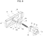
- the straight portion 55 has two vertical edges, which face one another along the axis 37 and can slide in two slits 60 ( figure 6 ), which are made in the bushing 45 in diametrically opposite positions.
- the element 62 also performs a cam function in order to cause the automatic movement of the step 26 to its vertical position during the upward movement of the bar 22.
- the step 26 has an end 64 which is diametrically opposite the footboard 28 relative to the hinge axis and comprises a tappet element 65.
- the element 65 is vertically aligned with the element 62, when the bar 22 is in the lowered position and the step 26 is in the horizontal position ( figure 4 ), and cooperates in contact with the element 62, when the bar 22 travels a final segment of the upward path ( figure 3 ) .
- the element 62 pushes the element 65 downward, thus exerting a lever action upon the step 26 in order to cause the end 64 to rotate downward and the footboard 28 upward, to the vertical position.
- the member 30 preferably comprises an end portion 66, which overlaps an end of the footboard 28, in a direction that is parallel to the axis 34, when the member 30 is arranged in the first and in the third position, so as to better hold the footboard 28 in the vertical position.
- the end portions 66 and 35 are at the opposite ends of the plate 32.
- step 26 automatically rotates to the horizontal position because of its own weight and/or because of the interaction between the elements 62 and 65 in the first segment of the downward movement.
- the bar 22 In order to take the system 1 back to the retracted configuration, first of all, the bar 22 needs to be manually lifted by acting upon the appendage 25 by a hand. At the end of this lifting, the footboard 28 is also lifted to the vertical position due to the action of the element 62 upon the element 65 ( figure 3 ).
- the step 26 remains locked in its vertical position due to the action of the element 62 and/or of the end portion 66.
- the door 3 can be closed so as to allow the car 2 to leave.
- the system 1 has a high degree of safety, even if it is completely mechanical, since it keeps the door 3 open when the step 26 is lowered and needs to be used. Indeed, thanks to the holding function performed by the end portion 35, users have to retract the system 1 before the train can start running again; indeed, leaving the system 1 in the extended configuration would mean trying to travel with an open door, which is not permitted by the safety systems of the railway vehicle.
- the system 1 cannot be shifted to the extended configuration if the door 3 is closed, because the leaf 12 physically prevents the member 30 from being moved to the second position, so that the stop device 31 remains active.
- the presence of the lock 36 and/or the need to axially move the pin 42 from the third to the first position before rotating the plate 32 allow for an increase in the degree of safety, as they prevent the system 1 from moving to the extended configuration in an autonomous and/or accidental manner.
- the system 1 can be extended and/or retraced by means of extremely simple manual operations, which can be carried out by one single operator.
- system 1 has extremely reduced size and can be installed as update or improvement in already produced and marketed vehicles, for it does not require special interactions with mechanical, electrical and electronic systems already present on board the car 2 (except for the positioning of the end portion 35, which is aimed at preventing the door 3 from closing).
- the member 30 could have different shapes and/or size and/or constructive features and/or movement paths, which are different from the ones described above by way of example, with reference to the plate 32 and/or to the pin 42; and/or the bar 22 could be replaced by another type of supporting element, for example a lever that can rotate between a raised position and a lowered position; and/or the system 1 could be built-in in the structure 9 of the upright 8 or be mounted on the side wall 6 or on the floor of the car 2; and/or the end portion 35 could be replaced by a different retention portion, even distinct from the member 30, which, tough, moves anyway in response to the activation of the member 30 so as to assume a projecting position, in which it prevents the door 3 from closing.
- the bar 22 could be replaced by another type of supporting element, for example a lever that can rotate between a raised position and a lowered position
- the system 1 could be built-in in the structure 9 of the upright 8 or be mounted on the side wall 6 or on the floor of the car 2
Landscapes
- Engineering & Computer Science (AREA)
- Mechanical Engineering (AREA)
- Vehicle Step Arrangements And Article Storage (AREA)
Abstract
Description
- This patent application claims priority from Italian patent application no.
102019000013872 filed on August 2, 2019 - The invention relates to a retractable step system for getting into and out of a vehicle, in particular for letting a motorman into and out of a railway vehicle, to which reference will be made in the description below without loosing in generality because of this.
- In the lead cars of trains, an additional step is needed in order to allow the motorman/driver to easily and safely get into and out of the car when the train has to stop in areas other than train stations, where suitable platforms are provided. In these areas, indeed, the height distance between the walking plane of the car and the ballast for the railway tracks can be relatively high, so that the steps that are usually provided on the train are not sufficient to allow the driver to safely get into and out of the car.
- In particular, since the size of railway vehicles, in cross section, cannot exceed the so-called structure gauge, which ensures the absence of interferences with fixed infrastructures, a retractable system is needed, namely a system having one or more steps that can be moved between an extended operating configuration (inevitably outside of the structure gauge) and a retracted rest position, which is reached in a completely mechanical manner and by means of hand operations, hence without electrical connections to the power supply systems and to the sensors of the train, but, nonetheless, capable of ensuring a high degree of safety and limited size. More in detail, the steps need to be capable of being moved back to the retracted rest position before the vehicle starts running again, so as to make sure that the structure gauge is restored.
- The object of the invention is to provide a retractable step system for getting into and out of a vehicle, which allows to fulfil the needs discussed above in a simple and economic fashion.
- According to the invention, there is provided a retractable step system for getting into and out of a vehicle according to
claim 1. - Furthermore, the invention relates to a vehicle door assembly according to
claim 14. - The invention will be best understood upon perusal of the following description of a preferred embodiment, provided by way of a mere explanatory, non-limiting example, with reference to the accompanying drawings, wherein:
-
figure 1 is a perspective view of a preferred embodiment of the retractable step system for getting into and out of a vehicle according to the present invention; -
figure 2 shows, on a larger scale and with parts removed for greater clarity, the system offigure 1 in a retracted rest configuration; -
figure 3 is similar tofigure 2 and shows the system according to the invention during a movement toward an extended operating configuration; -
figure 4 is similar tofigure 1 and shows the system arranged in the extended operating configuration, with parts removed for greater clarity; -
figure 5 is a detail of the system according to the invention in a cross section along a vertical section plane (identified by line V-V infigure 2 ) and shown in perspective from a different point of view; and -
figure 6 shows, in a perspective and exploded view, some components that are visible in the detail offigure 5 . - In
figure 1 ,reference number 1 indicates a retractable step system for getting into and out of a (partially shown)car 2, which preferably is part of a railway vehicle (which is not shown), through adoor 3. Thedoor 3 is arranged in the area of aside wall 6 of thecar 2 and comprises adoorway 5 and two uprights, which are arranged on opposite sides of thedoorway 5. Only one of the uprights is visible infigure 1 and is indicated withreference number 8. For example, the upright 8 has a supportingstructure 9 and afinishing lining 10, which is fixed to thestructure 9 so as to cover at least part of anouter surface 11 thereof. Thedoor 3 further comprises at least oneleaf 12, which is movable between a closing position (figure 1 ) and an opening position (figure 4 ) so as to close/open thedoorway 5, due to the action of an actuator device, which is not shown herein. - According to
figure 4 , in the opening position, theleaf 12 is preferably arranged behind the upright 8 and is parallel to theside wall 6; the movement of theleaf 12 between the opening position and the closing position comprises a translation component along ahorizontal direction 14, which is parallel to theside wall 6. - In particular, the
door 3 comprises astep 15, which is of known kind, is not described in detail and is arranged at the same level as, or under, the threshold of thedoorway 5, so as to allow drivers to go up and down between the walking plane of thecar 2 and the usual platforms normally provided in railway stations. According to an alternative which is not shown herein, thestep 15 could not be built-in in thedoor 3, but be a distinct component. - With reference to
figure 1 , thesystem 1 is supported by the upright 8 and is preferably arranged on thesurface 11 in the area of a lower zone, which is not covered by thelining 10. Thesystem 1 can be manually configured between a retracted rest configuration and an extended operating configuration. Based on what described in detail hereinafter, thesystem 1 is a merely mechanical system, namely is not provided with electrical/electronic parts. In the retracted configuration, thesystem 1 is arranged so as to be flush with the outer profile of thelining 10 or to project from the latter in an insignificant manner. - With reference to
figure 2 , thesystem 1 comprises anattachment structure 20, which is fixed to thestructure 9 and carries, in a fixed position, aguide 21. Thesystem 1 further comprises a supporting element, which, in the embodiment shown herein, is defined by avertical bar 22, which is coupled to theguide 21 so as to vertically slide between a raised rest position (figure 2 ), corresponding to the retracted position, and a lowered operating position (figure 4 ), corresponding to the extended configuration. Thebar 22 basically moves downward along theguide 21 because of the weight. - The
bar 22 comprises anupper portion 23, which, in the raised position, is housed in a compartment 24 (figure 1 ) arranged between thelining 10 and thesurface 11. Theupper portion 23 preferably carries anappendage 25, which projects through thelining 10, i.e. outside of thecompartment 24, so that it can manually be operated by a user in order to lift thebar 22 along theguide 21. - The
system 1 further comprises astep 26, which is coupled to alower end 27 of thebar 22 in a movable manner between a vertical rest position (figure 2 ), corresponding to the retracted configuration, and a horizontal support position (figure 4 ), corresponding to the extended configuration. Thestep 26 comprises a footboard orsupport portion 28, which, in the horizontal position, projects from thebar 22 along a horizontal axis 29 (figure 4 ), which is parallel to thedirection 14, so as to allow a foot to be placed on it. Thestep 26 is preferably hinged to theend 27 about a hinge axis, which is orthogonal to theaxis 29. - According to
figure 2 , in the vertical position, thefootboard 28 faces upward and horizontally faces thebar 22. - The
system 1 further comprises acontrol member 30, which is movable in response to a manual action of a user, and astop device 31, which is active and vertically holds thebar 22 in the raised position when themember 30 is arranged in a first position (represented with a broken line infigure 2 , where the horizontal distance from thebar 22 is shown out of scale for clarity reasons). Thestop device 31 is inactive and allows thebar 22 to freely move in a vertical manner between the raised position and the lowered position when themember 30 is arranged in a second position (shown infigures 3 and4 ), which is distinct from the first one. - According to
figure 1 , in particular, themember 30 comprises aplate 32, which, in the retracted configuration, is arranged in a recess orslot 33 of thelining 10, so that it is outside of thecompartment 24 and can easily be accessed. More in particular, thestep 26 is located in therecess 33 together with theplate 32 in the retracted configuration. - According to
figure 3 , in order to shift from the first to the second position and vice versa, themember 30 is manually rotated about arotation axis 34, which is parallel to theaxis 29, for example through a 90° rotation. - According to an aspect of the invention, the
member 30 comprises anend portion 35, which preferably is part of theplate 32 and, in the second position, projects toward the inside of thecar 2 along ahorizontal axis 37 orthogonal to theaxes 29 and 34 (relative to thebar 22 and in the place that was occupied by themember 30 in the first position). In this way, theend portion 35 projects past the upright 8 (figure 4 ) to as to intercept the path of theleaf 12 and fulfil a holding function which keeps thedoor 3 open. In particular, the vehicle is provided with known safety systems, which have a so-called "door sensitive edge" function, in order to prevent thedoor 3 from closing in the presence of obstacles. These systems are configured so as to recognize the presence of obstacles (in this case, the presence of the end portion 35), for example by detecting a greater resistance to the movement of theleaf 12, and, hence, to automatically stop the closing movement of theleaf 12 in order to prevent said obstacles from being crushed. - Therefore, the
door 3 can close and the train is allowed to leave (thanks to other known safety systems associated with the closing of the doors) only if themember 30 has been removed from said second position, namely only if thesystem 1 has been brought back to the retracted configuration. - According, in particular, to
figure 4 , when themember 30 is in the second position, theend portion 35 engages thedoorway 5 and, hence, faces an edge of theleaf 12 along thedirection 14. At the same time, when thedoor 3 is closed, theleaf 12 physically prevents theplate 32 from moving to the second position, so that thebar 22 cannot be lowered and thesystem 1 is kept in the retracted configuration. - According to an embodiment which is not shown herein, in the opening position, the
leaf 12 is arranged in front of the upright 8, outside of thecar 2; in this case, theend portion 35, in the second position, projects along theaxis 37 toward the outside of thecar 2. - According to a further embodiment which is not shown herein, when the
member 30 is in the second position offigure 3 , theend portion 35 engages a retention seat especially made in theleaf 12 in order to keep thedoor 3 open, instead of being in front of the edge of theleaf 12. - According to further embodiments which are not shown herein, the
member 30 and/or theend portion 35 can be replaced by components moving between the first and the second position with motions that are different from the rotary motion about theaxis 34, for example a translation motion along theaxis 37 or a rotary motion about a vertical axis. - The
system 1 preferably comprises, in addition, alock 36, which is configured so as to lock themember 30 to areference shoulder 38, in order to hold thesystem 1 in the retracted configuration. Thelock 36 can be released by means of a dedicated key or a standard key, so as to free themember 30. In particular, thelock 36 locks themember 30 in a third position, which corresponds to the retracted rest configuration, is distinct from the first position and is shown infigure 2 with a solid line. In order to shift from the first to the third position and vice versa, themember 30 follows a path that is different from the one extending between the first and the second position; in particular, themember 30 translates along theaxis 34. - With reference to
figure 5 , a spring 39 (or another equivalent elastic element) is interposed between thestructure 20 and themember 30 and is pre-loaded so as to automatically move themember 30 backward from the first to the third position. More in detail, thelock 36 is configured so as to automatically snap and engage theshoulder 38, in order to lock themember 30, when the latter has moved backward to the third position because of the action of the spring 39. - In particular, the
shoulder 38 is part of thebar 22; for example, theshoulder 38 is defined by an edge of a through hole, which is parallel to theaxis 34. - The third position fulfils an additional safety function in order to avoid accidental activations, but it could be absent (in these cases, the
lock 36 can lock themember 30 in the first position). - With reference to
figure 6 , thesystem 1 preferably further comprises adevice 40, which guides the movements of themember 30 to the first, the second and the third position. Themember 30 comprises apin 42, which is fixed to theplate 32 and projects from the latter along theaxis 34, whereas thedevice 40 comprises aseat 44, which is coaxial to thepin 42 and is engaged by the latter in a sliding manner. Theseat 44 is defined by a sleeve orbushing 45, which is part of thestructure 20 or is fixed to thestructure 20. Furthermore, thedevice 40 comprises aguide dowel 46, which radially projects inside theseat 44 from an inner surface of thebushing 45, and agroove 47, which is obtained along an outer surface of thepin 42 and is engaged by thedowel 46 in a sliding manner. - In particular, the
groove 47 comprises aportion 47a, which is straight and guides the axial translation of themember 30 between the third and the first position (also forbidding rotations about the axis 34), and aportion 47b, which is joined to theportion 47a and has the shape of an arc of a circle. Theportion 47b prevents thepin 42 from translating backward toward the third position due to the action of the spring 39 (besides guiding the rotation of themember 30 between the first and the second position). - Furthermore, the
groove 47 preferably defines the limit stops for the movements of themember 30. - According to variants which are not shown herein, the
dowel 46 and thegroove 47 are absent; or thedowel 46 radially projects from the outer surface of thepin 42, whereas thegroove 47 is obtained on the inner surface of thebushing 45. - The spring 39 is preferably housed in an axial cavity of the
pin 42 and is mounted in a way that is not described in detail (figure 5 ) so as to axially pull thepin 42. - Moreover, with reference to
figures 5 and6 , thepin 42 comprises a shapedportion 49, which is part of thestop device 31. In particular, the shapedportion 49 has acylindrical area 50a and a reduceddiameter area 50b, namely having a smaller diameter than thearea 50a. For example, thearea 50b is defined by two diametrically opposite flattened regions on the shapedportion 49. At the same time, thestop device 31 comprises anopening 52, which is made in thebar 22 and has alower end 53, which is engaged by thepin 42 when thebar 22 is arranged in the raised position. - The
end 53 is engaged by the shaped portion 49 (in a way that is not shown herein) when themember 30 is caused to move along theaxis 34 to the first position. - The
lower end 53 has a greater diameter than theareas portion 49 is free to rotate inside thelower end 53. In other words, in these conditions, themember 30 can be rotated about theaxis 34 in order to reach the second position (figure 3 ). - The
opening 52 further comprises astraight portion 55, which is vertical, is joined to thelower end 53 and has width, in horizontal, which is smaller than the diameter of thearea 50a and greater than the diameter of thearea 50b. The width narrowing from theend 53 to thestraight portion 55 defines two shoulders 56 (figures 4 and5 ), which are vertically aligned with the shapedportion 49, if thepin 42 is oriented in the first position, so as to vertically rest against thearea 50a and, hence, stop the downward movement of thebar 22. - According to
figure 5 , theshoulders 56 vertically rest against the outer surface of thepin 42 in order to stop the downward movement of thebar 22, even when themember 30 is axially arranged backward in the third position. - The
straight portion 55 can vertically slide along the shapedportion 49 only if thepin 42 is oriented in the second position, namely only when thearea 50b is capable to get into the straight portion 55 (namely, when the aforesaid flattened regions are vertical). Indeed, with this orientation, theshoulders 56 are no longer vertically aligned with the shapedportion 49 and, therefore, are not effective anymore, so that thebar 22 can lower due to the action of its own weight. - During the vertical sliding of the
bar 22, the narrowed width of thestraight portion 53 prevents the shapedportion 49 from rotating and, hence, prevents themember 30 from going back to the first position. In order to go back to the first position, indeed, thebar 22 needs to be manually lifted until the shapedportion 49 engages again thelower end 53 of theopening 52. In order to lift thebar 22, as already mentioned above, theappendage 25 has to be pushed upward. - Preferably, according to
figure 3 , thestraight portion 55 has two vertical edges, which face one another along theaxis 37 and can slide in two slits 60 (figure 6 ), which are made in thebushing 45 in diametrically opposite positions. - The
system 1 further comprises at least oneelement 62, which is carried by thestructure 20 in a fixed vertical position and vertically faces at least oneshoulder 63 of thebar 22, so as to stop thebar 22 when moving downward to the lowered position, thanks toshoulder 63 resting against the element 62 (figure 4 ). In particular, theelement 62 is defined by a pin, which is parallel to theaxis 37. - Besides fulfilling this limit stop function, the
element 62 also performs a cam function in order to cause the automatic movement of thestep 26 to its vertical position during the upward movement of thebar 22. Indeed, thestep 26 has anend 64 which is diametrically opposite thefootboard 28 relative to the hinge axis and comprises atappet element 65. Theelement 65 is vertically aligned with theelement 62, when thebar 22 is in the lowered position and thestep 26 is in the horizontal position (figure 4 ), and cooperates in contact with theelement 62, when thebar 22 travels a final segment of the upward path (figure 3 ) . During the lifting of thebar 22, theelement 62 pushes theelement 65 downward, thus exerting a lever action upon thestep 26 in order to cause theend 64 to rotate downward and thefootboard 28 upward, to the vertical position. - Once the
bar 22 has reached its raised position, theelement 62 engages theelement 65 so as to keep thestep 26 in its vertical position. In order to have an additional degree of safety, according tofigure 2 , themember 30 preferably comprises anend portion 66, which overlaps an end of thefootboard 28, in a direction that is parallel to theaxis 34, when themember 30 is arranged in the first and in the third position, so as to better hold thefootboard 28 in the vertical position. In particular, theend portions plate 32. - Owing to the above, it is evident that, in use, in order to move the
system 1 from the retracted configuration to the extended configuration, it is necessary to carry out the following manual operations in sequence, after having opened the door 3: - releasing the
lock 36 by means of the corresponding key; - moving the
member 30 from the third to the first position, pulling theplate 32 against the action of the spring 39 (figure 2 ); - moving the
member 30 from the first to the second position (figure 3 ). - Through the last movement, it simultaneously occurs that:
- the
leaf 12 is locked by theend portion 35 in the open position; - the
bar 22 can freely move downward because of its own weight. - Finally, during the downward movement of the
bar 22, thestep 26 automatically rotates to the horizontal position because of its own weight and/or because of the interaction between theelements - When the
bar 22 reaches the lowered position (figure 4 ), thefootboard 28 can be used to get into thecar 2 and/or out of the latter. In particular, thestep 26 reaches a height below thestep 15, adding itself to the latter in order to allow the driver to easily get into and out of the train even when thecar 2 does not stop in the area of a platform. - In order to take the
system 1 back to the retracted configuration, first of all, thebar 22 needs to be manually lifted by acting upon theappendage 25 by a hand. At the end of this lifting, thefootboard 28 is also lifted to the vertical position due to the action of theelement 62 upon the element 65 (figure 3 ). - Then, keeping the
appendage 25 raised, the other hand is used to move themember 30 from the second to the first position (figure 2 ). At this point, by simply letting go off themember 30, the latter automatically and quickly moves backward to the third position because of the effect of the spring 39 and, at the end of this movement, thelock 36 automatically snaps so as to lock thesystem 1, without having to use the key again (figure 2 ). - In particular, besides locking the
bar 22 in its raised position, thestep 26 remains locked in its vertical position due to the action of theelement 62 and/or of theend portion 66. - Finally, since the
end portion 35 does not hinder theleaf 12 any longer, thedoor 3 can be closed so as to allow thecar 2 to leave. - Owing to the above, the advantages of the
system 1 described above with reference to the accompanying drawings are evident. In particular, thesystem 1 has a high degree of safety, even if it is completely mechanical, since it keeps thedoor 3 open when thestep 26 is lowered and needs to be used. Indeed, thanks to the holding function performed by theend portion 35, users have to retract thesystem 1 before the train can start running again; indeed, leaving thesystem 1 in the extended configuration would mean trying to travel with an open door, which is not permitted by the safety systems of the railway vehicle. - At the same time, the
system 1 cannot be shifted to the extended configuration if thedoor 3 is closed, because theleaf 12 physically prevents themember 30 from being moved to the second position, so that thestop device 31 remains active. - Then, the presence of the
lock 36 and/or the need to axially move thepin 42 from the third to the first position before rotating theplate 32 allow for an increase in the degree of safety, as they prevent thesystem 1 from moving to the extended configuration in an autonomous and/or accidental manner. At the same time, thesystem 1 can be extended and/or retraced by means of extremely simple manual operations, which can be carried out by one single operator. - Furthermore, the
system 1 has extremely reduced size and can be installed as update or improvement in already produced and marketed vehicles, for it does not require special interactions with mechanical, electrical and electronic systems already present on board the car 2 (except for the positioning of theend portion 35, which is aimed at preventing thedoor 3 from closing). - Owing to the above, finally, the
system 1 described and shown herein can evidently be subjected to changes and variations that do not go beyond the scope of protection of the invention, as set forth in the appended claims. - In particular, the
member 30 could have different shapes and/or size and/or constructive features and/or movement paths, which are different from the ones described above by way of example, with reference to theplate 32 and/or to thepin 42; and/or thebar 22 could be replaced by another type of supporting element, for example a lever that can rotate between a raised position and a lowered position; and/or thesystem 1 could be built-in in thestructure 9 of theupright 8 or be mounted on theside wall 6 or on the floor of thecar 2; and/or theend portion 35 could be replaced by a different retention portion, even distinct from themember 30, which, tough, moves anyway in response to the activation of themember 30 so as to assume a projecting position, in which it prevents thedoor 3 from closing. - Furthermore, different steps can be provided, for example two steps, arranged at two different heights on one single supporting element or arranged on two different systems, similar to the one described above, one on the right and one on the left of the
door 3, in case the height between the walking plane of thecar 2 and the ballast is particularly great.
Claims (15)
- A retractable-step system (1) for getting into and out of a vehicle, the system comprising:- at least one step (26); and- a supporting element (22), which carries said step (26) and is movable between a raised position and a lowered position; in the lowered position said step (26) projecting from said supporting element (22) along a first horizontal axis (29);characterized by further comprising:- a control member (30), which can be operated manually for being displaced between a first position and a second position;- a stop device (31), which is activated and deactivated in response to the displacement of said control member (30) so as to withhold said supporting element (22) in the raised position when said control member (30) is arranged in the first position and so as to leave said supporting element (22) free to move into the lowered position when said control member (30) is arranged in the second position; and- a retention portion (35), which, in the second position of said control member (30), projects along a second horizontal axis (37) orthogonal to said first horizontal axis (29) so as to keep a vehicle door (3) open, in use.
- The system according to claim 1, characterised in that said retention portion (35) is defined by an end portion of said control member (30).
- The system according to claim 1 or 2, characterised by comprising a lock (36) that can be released by a key and constrains said control member (30) to a reference shoulder (38) so as to prevent said control member (30) from being displaced into the second position.
- The system according to any one of the preceding claims, characterised in that said control member (30) moves between said first and second positions with a rotary motion about a rotation axis (34).
- The system according to any one of the preceding claims, characterised in that said stop device (31) comprises:- a stop body (42) forming part of said supporting member (30); and- at least one shoulder (56) which forms part of said supporting element (22) and rests vertically on said stop body (42) if said stop body (42) is arranged in the first position.
- The system according to claim 5, characterised in that said control member (30) is moreover movable between the first position and a third position along a path different from the one provided between the first and second positions; and characterized by comprising at least one elastic element (39) that is preloaded to bring said control member (30) automatically from the first position into the third position.
- The system according to claim 6, characterised in that said shoulder (56) rests vertically on said stop body (42) if said stop body (42) is arranged in the third position.
- The system according to claim 6 or 7, characterised in that said control member (30) moves between said first and third positions with a translational motion parallel to said first horizontal axis (29).
- The system according to any one of claims 5 to 8, characterised in that said stop body (42) is defined by a pin (42) that extends along an axis (34) and engages an opening (52) made in said supporting element (22).
- The system according to claim 9, characterised in that said shoulder (56) is defined by a narrowing of width of said opening (52).
- The system according to claim 9 or 10, characterised in that said pin (42) comprises a shaped portion (49) having:- a first area (50a) having a shape and/or size such as to be vertically aligned with said shoulder (56) when said control member (30) is arranged in the first position to stop lowering of said supporting element (22), and- a second area (50b) having a shape and/or size such as not to be vertically aligned with said shoulder (56) when said control member (30) is arranged in the second position to allow said supporting element (22) to lower.
- The system according to any one of the preceding claims, characterised in that said supporting element (22) is defined by a vertically translating bar.
- The system according to any one of the preceding claims, characterised in that said step (26) is coupled to said supporting element (22) so as to move between a vertical position and a horizontal position; and characterized by comprising a cam-and-tappet device (62, 64) for displacing said step (26) automatically into the vertical position when said supporting element (22) is displaced into the raised position.
- A door assembly comprising a door (3) and a retractable-step system (1) according to any one of the preceding claims; said door (3) comprising:- a doorway (5); and- at least one leaf (12) movable along a path for opening/closing said doorway (5);in the second position of said control member (30), said retention portion (35) being arranged in a position such as to intercept said path and keep said door open.
- The door assembly according to claim 14, characterised in that, in the second position of said control member (30), said retention portion (35) engages said doorway (5).
Applications Claiming Priority (1)
| Application Number | Priority Date | Filing Date | Title |
|---|---|---|---|
| IT102019000013872A IT201900013872A1 (en) | 2019-08-02 | 2019-08-02 | RETRACTABLE STEP SYSTEM FOR ASCENT AND DESCENT IN A VEHICLE, AND VEHICLE DOOR UNIT EQUIPPED WITH THIS SYSTEM |
Publications (2)
| Publication Number | Publication Date |
|---|---|
| EP3771607A1 true EP3771607A1 (en) | 2021-02-03 |
| EP3771607B1 EP3771607B1 (en) | 2023-01-04 |
Family
ID=69105964
Family Applications (1)
| Application Number | Title | Priority Date | Filing Date |
|---|---|---|---|
| EP20188440.0A Active EP3771607B1 (en) | 2019-08-02 | 2020-07-29 | Vehicle door assembly provided with a retractable step system for getting into and out of the vehicle |
Country Status (4)
| Country | Link |
|---|---|
| US (1) | US11312307B2 (en) |
| EP (1) | EP3771607B1 (en) |
| JP (1) | JP7526607B2 (en) |
| IT (1) | IT201900013872A1 (en) |
Citations (6)
| Publication number | Priority date | Publication date | Assignee | Title |
|---|---|---|---|---|
| US1042895A (en) * | 1911-11-25 | 1912-10-29 | Frank L Desens | Car-step. |
| US1052364A (en) * | 1912-04-26 | 1913-02-04 | Herbert W Ridgely | Car-step attachment. |
| US1109224A (en) * | 1913-05-06 | 1914-09-01 | Bervin E Herrin | Extension car-step. |
| US4071260A (en) * | 1976-10-05 | 1978-01-31 | Marshall Sr James A | Easy cab entry and exit |
| US6263804B1 (en) * | 1999-07-22 | 2001-07-24 | Tekdata Inc. | Dual level access door system for railway vehicles |
| US7699328B2 (en) * | 2007-07-16 | 2010-04-20 | Timberpro Inc. | Retractable step for cab of mobile machine |
Family Cites Families (7)
| Publication number | Priority date | Publication date | Assignee | Title |
|---|---|---|---|---|
| US3033309A (en) * | 1959-11-06 | 1962-05-08 | Fugere Dale | Retractible stepladder for vehicles |
| US4324317A (en) * | 1980-01-28 | 1982-04-13 | Winkelblech Dean R | Elevator device |
| JP4344559B2 (en) | 2003-07-23 | 2009-10-14 | 東日本旅客鉄道株式会社 | Vehicle movement prohibition device |
| JP4476869B2 (en) | 2005-05-09 | 2010-06-09 | 大東プレス工業株式会社 | Step device for getting on and off vehicle |
| DE102012214089A1 (en) * | 2012-08-08 | 2014-02-13 | Siemens Aktiengesellschaft | Vehicle with telescopic ladder |
| US9555743B2 (en) * | 2015-05-22 | 2017-01-31 | Roy A. Schut | Driver lift device |
| US9862324B2 (en) * | 2015-05-22 | 2018-01-09 | Roy A. Schut | Driver lift device |
-
2019
- 2019-08-02 IT IT102019000013872A patent/IT201900013872A1/en unknown
-
2020
- 2020-07-29 EP EP20188440.0A patent/EP3771607B1/en active Active
- 2020-07-30 US US16/943,455 patent/US11312307B2/en active Active
- 2020-07-31 JP JP2020130477A patent/JP7526607B2/en active Active
Patent Citations (6)
| Publication number | Priority date | Publication date | Assignee | Title |
|---|---|---|---|---|
| US1042895A (en) * | 1911-11-25 | 1912-10-29 | Frank L Desens | Car-step. |
| US1052364A (en) * | 1912-04-26 | 1913-02-04 | Herbert W Ridgely | Car-step attachment. |
| US1109224A (en) * | 1913-05-06 | 1914-09-01 | Bervin E Herrin | Extension car-step. |
| US4071260A (en) * | 1976-10-05 | 1978-01-31 | Marshall Sr James A | Easy cab entry and exit |
| US6263804B1 (en) * | 1999-07-22 | 2001-07-24 | Tekdata Inc. | Dual level access door system for railway vehicles |
| US7699328B2 (en) * | 2007-07-16 | 2010-04-20 | Timberpro Inc. | Retractable step for cab of mobile machine |
Also Published As
| Publication number | Publication date |
|---|---|
| US11312307B2 (en) | 2022-04-26 |
| JP7526607B2 (en) | 2024-08-01 |
| IT201900013872A1 (en) | 2021-02-02 |
| US20210031697A1 (en) | 2021-02-04 |
| JP2021024566A (en) | 2021-02-22 |
| EP3771607B1 (en) | 2023-01-04 |
Similar Documents
| Publication | Publication Date | Title |
|---|---|---|
| US8245447B2 (en) | Slide door assembly with safety device | |
| EP3421700B1 (en) | Door operator system, emergency release device and door isolation lock for a transit vehicle door | |
| EP1863733B1 (en) | Safety lock for elevator landing door detecting intrusion in the shaft through the landing door and elevator thus equipped | |
| EP3461780B1 (en) | Mechanical hoistway access control device | |
| EP3771607B1 (en) | Vehicle door assembly provided with a retractable step system for getting into and out of the vehicle | |
| US8794688B2 (en) | Door assembly for a vehicle | |
| JP2005127122A (en) | Glass interlock device for sliding door | |
| KR101220394B1 (en) | Door locking assembly for vehicle | |
| US20130257064A1 (en) | Heart shaped lock with sliding breakaway feature | |
| KR20200085583A (en) | Hold open latch structure of opposing sliding doors of vehicle | |
| EP3847329A2 (en) | Locking mechanism with additional damping mechanism | |
| KR101134381B1 (en) | Apparatus for preventing clash of sliding door and fuel filler door in vehicle | |
| US20150048630A1 (en) | Door locking device for truck | |
| JP6203368B1 (en) | Sliding door device | |
| KR100530117B1 (en) | Window safety apparatus of sliding door | |
| KR101976326B1 (en) | Blocking device and safty device of parking system using this | |
| US11772937B2 (en) | Elevator car door control system | |
| KR20140006529A (en) | Hold open latch for sliding door | |
| KR100539421B1 (en) | Safety apparatus for slide door of vehicle | |
| KR100539420B1 (en) | Safety apparatus for slide door of vehicle | |
| JP4993269B2 (en) | Structure for preventing unauthorized opening of vehicle doors | |
| KR101593514B1 (en) | Locking apparatus of seat sliding unit for automobile | |
| JP4870138B2 (en) | Door holding device | |
| JP2011169074A (en) | Fire shutter device with wing door | |
| JPH08158725A (en) | Door latch device |
Legal Events
| Date | Code | Title | Description |
|---|---|---|---|
| PUAI | Public reference made under article 153(3) epc to a published international application that has entered the european phase |
Free format text: ORIGINAL CODE: 0009012 |
|
| STAA | Information on the status of an ep patent application or granted ep patent |
Free format text: STATUS: THE APPLICATION HAS BEEN PUBLISHED |
|
| AK | Designated contracting states |
Kind code of ref document: A1 Designated state(s): AL AT BE BG CH CY CZ DE DK EE ES FI FR GB GR HR HU IE IS IT LI LT LU LV MC MK MT NL NO PL PT RO RS SE SI SK SM TR |
|
| AX | Request for extension of the european patent |
Extension state: BA ME |
|
| STAA | Information on the status of an ep patent application or granted ep patent |
Free format text: STATUS: REQUEST FOR EXAMINATION WAS MADE |
|
| 17P | Request for examination filed |
Effective date: 20210719 |
|
| RBV | Designated contracting states (corrected) |
Designated state(s): AL AT BE BG CH CY CZ DE DK EE ES FI FR GB GR HR HU IE IS IT LI LT LU LV MC MK MT NL NO PL PT RO RS SE SI SK SM TR |
|
| GRAP | Despatch of communication of intention to grant a patent |
Free format text: ORIGINAL CODE: EPIDOSNIGR1 |
|
| STAA | Information on the status of an ep patent application or granted ep patent |
Free format text: STATUS: GRANT OF PATENT IS INTENDED |
|
| RIC1 | Information provided on ipc code assigned before grant |
Ipc: B60R 3/02 20060101ALI20220602BHEP Ipc: B61D 23/02 20060101AFI20220602BHEP |
|
| INTG | Intention to grant announced |
Effective date: 20220705 |
|
| RAP1 | Party data changed (applicant data changed or rights of an application transferred) |
Owner name: HITACHI RAIL STS S.P.A. |
|
| GRAJ | Information related to disapproval of communication of intention to grant by the applicant or resumption of examination proceedings by the epo deleted |
Free format text: ORIGINAL CODE: EPIDOSDIGR1 |
|
| STAA | Information on the status of an ep patent application or granted ep patent |
Free format text: STATUS: REQUEST FOR EXAMINATION WAS MADE |
|
| GRAP | Despatch of communication of intention to grant a patent |
Free format text: ORIGINAL CODE: EPIDOSNIGR1 |
|
| STAA | Information on the status of an ep patent application or granted ep patent |
Free format text: STATUS: GRANT OF PATENT IS INTENDED |
|
| INTC | Intention to grant announced (deleted) | ||
| GRAS | Grant fee paid |
Free format text: ORIGINAL CODE: EPIDOSNIGR3 |
|
| INTG | Intention to grant announced |
Effective date: 20221026 |
|
| GRAA | (expected) grant |
Free format text: ORIGINAL CODE: 0009210 |
|
| STAA | Information on the status of an ep patent application or granted ep patent |
Free format text: STATUS: THE PATENT HAS BEEN GRANTED |
|
| AK | Designated contracting states |
Kind code of ref document: B1 Designated state(s): AL AT BE BG CH CY CZ DE DK EE ES FI FR GB GR HR HU IE IS IT LI LT LU LV MC MK MT NL NO PL PT RO RS SE SI SK SM TR |
|
| REG | Reference to a national code |
Ref country code: GB Ref legal event code: FG4D |
|
| REG | Reference to a national code |
Ref country code: CH Ref legal event code: EP |
|
| REG | Reference to a national code |
Ref country code: AT Ref legal event code: REF Ref document number: 1541749 Country of ref document: AT Kind code of ref document: T Effective date: 20230115 |
|
| REG | Reference to a national code |
Ref country code: DE Ref legal event code: R096 Ref document number: 602020007313 Country of ref document: DE |
|
| REG | Reference to a national code |
Ref country code: IE Ref legal event code: FG4D |
|
| REG | Reference to a national code |
Ref country code: LT Ref legal event code: MG9D |
|
| REG | Reference to a national code |
Ref country code: NL Ref legal event code: MP Effective date: 20230104 |
|
| REG | Reference to a national code |
Ref country code: AT Ref legal event code: MK05 Ref document number: 1541749 Country of ref document: AT Kind code of ref document: T Effective date: 20230104 |
|
| PG25 | Lapsed in a contracting state [announced via postgrant information from national office to epo] |
Ref country code: NL Free format text: LAPSE BECAUSE OF FAILURE TO SUBMIT A TRANSLATION OF THE DESCRIPTION OR TO PAY THE FEE WITHIN THE PRESCRIBED TIME-LIMIT Effective date: 20230104 |
|
| PG25 | Lapsed in a contracting state [announced via postgrant information from national office to epo] |
Ref country code: RS Free format text: LAPSE BECAUSE OF FAILURE TO SUBMIT A TRANSLATION OF THE DESCRIPTION OR TO PAY THE FEE WITHIN THE PRESCRIBED TIME-LIMIT Effective date: 20230104 Ref country code: PT Free format text: LAPSE BECAUSE OF FAILURE TO SUBMIT A TRANSLATION OF THE DESCRIPTION OR TO PAY THE FEE WITHIN THE PRESCRIBED TIME-LIMIT Effective date: 20230504 Ref country code: NO Free format text: LAPSE BECAUSE OF FAILURE TO SUBMIT A TRANSLATION OF THE DESCRIPTION OR TO PAY THE FEE WITHIN THE PRESCRIBED TIME-LIMIT Effective date: 20230404 Ref country code: LV Free format text: LAPSE BECAUSE OF FAILURE TO SUBMIT A TRANSLATION OF THE DESCRIPTION OR TO PAY THE FEE WITHIN THE PRESCRIBED TIME-LIMIT Effective date: 20230104 Ref country code: LT Free format text: LAPSE BECAUSE OF FAILURE TO SUBMIT A TRANSLATION OF THE DESCRIPTION OR TO PAY THE FEE WITHIN THE PRESCRIBED TIME-LIMIT Effective date: 20230104 Ref country code: HR Free format text: LAPSE BECAUSE OF FAILURE TO SUBMIT A TRANSLATION OF THE DESCRIPTION OR TO PAY THE FEE WITHIN THE PRESCRIBED TIME-LIMIT Effective date: 20230104 Ref country code: ES Free format text: LAPSE BECAUSE OF FAILURE TO SUBMIT A TRANSLATION OF THE DESCRIPTION OR TO PAY THE FEE WITHIN THE PRESCRIBED TIME-LIMIT Effective date: 20230104 Ref country code: AT Free format text: LAPSE BECAUSE OF FAILURE TO SUBMIT A TRANSLATION OF THE DESCRIPTION OR TO PAY THE FEE WITHIN THE PRESCRIBED TIME-LIMIT Effective date: 20230104 |
|
| PG25 | Lapsed in a contracting state [announced via postgrant information from national office to epo] |
Ref country code: SE Free format text: LAPSE BECAUSE OF FAILURE TO SUBMIT A TRANSLATION OF THE DESCRIPTION OR TO PAY THE FEE WITHIN THE PRESCRIBED TIME-LIMIT Effective date: 20230104 Ref country code: PL Free format text: LAPSE BECAUSE OF FAILURE TO SUBMIT A TRANSLATION OF THE DESCRIPTION OR TO PAY THE FEE WITHIN THE PRESCRIBED TIME-LIMIT Effective date: 20230104 Ref country code: IS Free format text: LAPSE BECAUSE OF FAILURE TO SUBMIT A TRANSLATION OF THE DESCRIPTION OR TO PAY THE FEE WITHIN THE PRESCRIBED TIME-LIMIT Effective date: 20230504 Ref country code: GR Free format text: LAPSE BECAUSE OF FAILURE TO SUBMIT A TRANSLATION OF THE DESCRIPTION OR TO PAY THE FEE WITHIN THE PRESCRIBED TIME-LIMIT Effective date: 20230405 Ref country code: FI Free format text: LAPSE BECAUSE OF FAILURE TO SUBMIT A TRANSLATION OF THE DESCRIPTION OR TO PAY THE FEE WITHIN THE PRESCRIBED TIME-LIMIT Effective date: 20230104 |
|
| REG | Reference to a national code |
Ref country code: DE Ref legal event code: R097 Ref document number: 602020007313 Country of ref document: DE |
|
| PG25 | Lapsed in a contracting state [announced via postgrant information from national office to epo] |
Ref country code: SM Free format text: LAPSE BECAUSE OF FAILURE TO SUBMIT A TRANSLATION OF THE DESCRIPTION OR TO PAY THE FEE WITHIN THE PRESCRIBED TIME-LIMIT Effective date: 20230104 Ref country code: RO Free format text: LAPSE BECAUSE OF FAILURE TO SUBMIT A TRANSLATION OF THE DESCRIPTION OR TO PAY THE FEE WITHIN THE PRESCRIBED TIME-LIMIT Effective date: 20230104 Ref country code: EE Free format text: LAPSE BECAUSE OF FAILURE TO SUBMIT A TRANSLATION OF THE DESCRIPTION OR TO PAY THE FEE WITHIN THE PRESCRIBED TIME-LIMIT Effective date: 20230104 Ref country code: DK Free format text: LAPSE BECAUSE OF FAILURE TO SUBMIT A TRANSLATION OF THE DESCRIPTION OR TO PAY THE FEE WITHIN THE PRESCRIBED TIME-LIMIT Effective date: 20230104 Ref country code: CZ Free format text: LAPSE BECAUSE OF FAILURE TO SUBMIT A TRANSLATION OF THE DESCRIPTION OR TO PAY THE FEE WITHIN THE PRESCRIBED TIME-LIMIT Effective date: 20230104 |
|
| PLBE | No opposition filed within time limit |
Free format text: ORIGINAL CODE: 0009261 |
|
| STAA | Information on the status of an ep patent application or granted ep patent |
Free format text: STATUS: NO OPPOSITION FILED WITHIN TIME LIMIT |
|
| PG25 | Lapsed in a contracting state [announced via postgrant information from national office to epo] |
Ref country code: SK Free format text: LAPSE BECAUSE OF FAILURE TO SUBMIT A TRANSLATION OF THE DESCRIPTION OR TO PAY THE FEE WITHIN THE PRESCRIBED TIME-LIMIT Effective date: 20230104 |
|
| 26N | No opposition filed |
Effective date: 20231005 |
|
| PG25 | Lapsed in a contracting state [announced via postgrant information from national office to epo] |
Ref country code: SI Free format text: LAPSE BECAUSE OF FAILURE TO SUBMIT A TRANSLATION OF THE DESCRIPTION OR TO PAY THE FEE WITHIN THE PRESCRIBED TIME-LIMIT Effective date: 20230104 |
|
| PG25 | Lapsed in a contracting state [announced via postgrant information from national office to epo] |
Ref country code: MC Free format text: LAPSE BECAUSE OF FAILURE TO SUBMIT A TRANSLATION OF THE DESCRIPTION OR TO PAY THE FEE WITHIN THE PRESCRIBED TIME-LIMIT Effective date: 20230104 |
|
| PG25 | Lapsed in a contracting state [announced via postgrant information from national office to epo] |
Ref country code: MC Free format text: LAPSE BECAUSE OF FAILURE TO SUBMIT A TRANSLATION OF THE DESCRIPTION OR TO PAY THE FEE WITHIN THE PRESCRIBED TIME-LIMIT Effective date: 20230104 |
|
| REG | Reference to a national code |
Ref country code: BE Ref legal event code: MM Effective date: 20230731 |
|
| PG25 | Lapsed in a contracting state [announced via postgrant information from national office to epo] |
Ref country code: LU Free format text: LAPSE BECAUSE OF NON-PAYMENT OF DUE FEES Effective date: 20230729 |
|
| PG25 | Lapsed in a contracting state [announced via postgrant information from national office to epo] |
Ref country code: LU Free format text: LAPSE BECAUSE OF NON-PAYMENT OF DUE FEES Effective date: 20230729 |
|
| REG | Reference to a national code |
Ref country code: IE Ref legal event code: MM4A |
|
| PG25 | Lapsed in a contracting state [announced via postgrant information from national office to epo] |
Ref country code: IT Free format text: LAPSE BECAUSE OF FAILURE TO SUBMIT A TRANSLATION OF THE DESCRIPTION OR TO PAY THE FEE WITHIN THE PRESCRIBED TIME-LIMIT Effective date: 20230104 Ref country code: BE Free format text: LAPSE BECAUSE OF NON-PAYMENT OF DUE FEES Effective date: 20230731 |
|
| P01 | Opt-out of the competence of the unified patent court (upc) registered |
Effective date: 20240430 |
|
| PG25 | Lapsed in a contracting state [announced via postgrant information from national office to epo] |
Ref country code: IE Free format text: LAPSE BECAUSE OF NON-PAYMENT OF DUE FEES Effective date: 20230729 |
|
| PG25 | Lapsed in a contracting state [announced via postgrant information from national office to epo] |
Ref country code: IE Free format text: LAPSE BECAUSE OF NON-PAYMENT OF DUE FEES Effective date: 20230729 |
|
| PG25 | Lapsed in a contracting state [announced via postgrant information from national office to epo] |
Ref country code: BG Free format text: LAPSE BECAUSE OF FAILURE TO SUBMIT A TRANSLATION OF THE DESCRIPTION OR TO PAY THE FEE WITHIN THE PRESCRIBED TIME-LIMIT Effective date: 20230104 |
|
| PG25 | Lapsed in a contracting state [announced via postgrant information from national office to epo] |
Ref country code: BG Free format text: LAPSE BECAUSE OF FAILURE TO SUBMIT A TRANSLATION OF THE DESCRIPTION OR TO PAY THE FEE WITHIN THE PRESCRIBED TIME-LIMIT Effective date: 20230104 |
|
| PG25 | Lapsed in a contracting state [announced via postgrant information from national office to epo] |
Ref country code: CY Free format text: LAPSE BECAUSE OF FAILURE TO SUBMIT A TRANSLATION OF THE DESCRIPTION OR TO PAY THE FEE WITHIN THE PRESCRIBED TIME-LIMIT; INVALID AB INITIO Effective date: 20200729 |
|
| PG25 | Lapsed in a contracting state [announced via postgrant information from national office to epo] |
Ref country code: HU Free format text: LAPSE BECAUSE OF FAILURE TO SUBMIT A TRANSLATION OF THE DESCRIPTION OR TO PAY THE FEE WITHIN THE PRESCRIBED TIME-LIMIT; INVALID AB INITIO Effective date: 20200729 |
|
| PGFP | Annual fee paid to national office [announced via postgrant information from national office to epo] |
Ref country code: DE Payment date: 20250728 Year of fee payment: 6 |
|
| PGFP | Annual fee paid to national office [announced via postgrant information from national office to epo] |
Ref country code: GB Payment date: 20250722 Year of fee payment: 6 |
|
| PGFP | Annual fee paid to national office [announced via postgrant information from national office to epo] |
Ref country code: FR Payment date: 20250725 Year of fee payment: 6 |
|
| PGFP | Annual fee paid to national office [announced via postgrant information from national office to epo] |
Ref country code: CH Payment date: 20250801 Year of fee payment: 6 |
|
| PG25 | Lapsed in a contracting state [announced via postgrant information from national office to epo] |
Ref country code: TR Free format text: LAPSE BECAUSE OF FAILURE TO SUBMIT A TRANSLATION OF THE DESCRIPTION OR TO PAY THE FEE WITHIN THE PRESCRIBED TIME-LIMIT Effective date: 20230104 |