EP3771581A1 - A vehicle system for use in confined buildings - Google Patents
A vehicle system for use in confined buildings Download PDFInfo
- Publication number
- EP3771581A1 EP3771581A1 EP20188503.5A EP20188503A EP3771581A1 EP 3771581 A1 EP3771581 A1 EP 3771581A1 EP 20188503 A EP20188503 A EP 20188503A EP 3771581 A1 EP3771581 A1 EP 3771581A1
- Authority
- EP
- European Patent Office
- Prior art keywords
- generator
- motor
- vehicle
- power
- power transmission
- Prior art date
- Legal status (The legal status is an assumption and is not a legal conclusion. Google has not performed a legal analysis and makes no representation as to the accuracy of the status listed.)
- Granted
Links
Images

Classifications
-
- B—PERFORMING OPERATIONS; TRANSPORTING
- B60—VEHICLES IN GENERAL
- B60K—ARRANGEMENT OR MOUNTING OF PROPULSION UNITS OR OF TRANSMISSIONS IN VEHICLES; ARRANGEMENT OR MOUNTING OF PLURAL DIVERSE PRIME-MOVERS IN VEHICLES; AUXILIARY DRIVES FOR VEHICLES; INSTRUMENTATION OR DASHBOARDS FOR VEHICLES; ARRANGEMENTS IN CONNECTION WITH COOLING, AIR INTAKE, GAS EXHAUST OR FUEL SUPPLY OF PROPULSION UNITS IN VEHICLES
- B60K6/00—Arrangement or mounting of plural diverse prime-movers for mutual or common propulsion, e.g. hybrid propulsion systems comprising electric motors and internal combustion engines
- B60K6/20—Arrangement or mounting of plural diverse prime-movers for mutual or common propulsion, e.g. hybrid propulsion systems comprising electric motors and internal combustion engines the prime-movers consisting of electric motors and internal combustion engines, e.g. HEVs
- B60K6/42—Arrangement or mounting of plural diverse prime-movers for mutual or common propulsion, e.g. hybrid propulsion systems comprising electric motors and internal combustion engines the prime-movers consisting of electric motors and internal combustion engines, e.g. HEVs characterised by the architecture of the hybrid electric vehicle
- B60K6/48—Parallel type
-
- B—PERFORMING OPERATIONS; TRANSPORTING
- B60—VEHICLES IN GENERAL
- B60K—ARRANGEMENT OR MOUNTING OF PROPULSION UNITS OR OF TRANSMISSIONS IN VEHICLES; ARRANGEMENT OR MOUNTING OF PLURAL DIVERSE PRIME-MOVERS IN VEHICLES; AUXILIARY DRIVES FOR VEHICLES; INSTRUMENTATION OR DASHBOARDS FOR VEHICLES; ARRANGEMENTS IN CONNECTION WITH COOLING, AIR INTAKE, GAS EXHAUST OR FUEL SUPPLY OF PROPULSION UNITS IN VEHICLES
- B60K17/00—Arrangement or mounting of transmissions in vehicles
- B60K17/28—Arrangement or mounting of transmissions in vehicles characterised by arrangement, location, or type of power take-off
-
- B—PERFORMING OPERATIONS; TRANSPORTING
- B60—VEHICLES IN GENERAL
- B60K—ARRANGEMENT OR MOUNTING OF PROPULSION UNITS OR OF TRANSMISSIONS IN VEHICLES; ARRANGEMENT OR MOUNTING OF PLURAL DIVERSE PRIME-MOVERS IN VEHICLES; AUXILIARY DRIVES FOR VEHICLES; INSTRUMENTATION OR DASHBOARDS FOR VEHICLES; ARRANGEMENTS IN CONNECTION WITH COOLING, AIR INTAKE, GAS EXHAUST OR FUEL SUPPLY OF PROPULSION UNITS IN VEHICLES
- B60K17/00—Arrangement or mounting of transmissions in vehicles
- B60K17/34—Arrangement or mounting of transmissions in vehicles for driving both front and rear wheels, e.g. four wheel drive vehicles
-
- B—PERFORMING OPERATIONS; TRANSPORTING
- B60—VEHICLES IN GENERAL
- B60K—ARRANGEMENT OR MOUNTING OF PROPULSION UNITS OR OF TRANSMISSIONS IN VEHICLES; ARRANGEMENT OR MOUNTING OF PLURAL DIVERSE PRIME-MOVERS IN VEHICLES; AUXILIARY DRIVES FOR VEHICLES; INSTRUMENTATION OR DASHBOARDS FOR VEHICLES; ARRANGEMENTS IN CONNECTION WITH COOLING, AIR INTAKE, GAS EXHAUST OR FUEL SUPPLY OF PROPULSION UNITS IN VEHICLES
- B60K6/00—Arrangement or mounting of plural diverse prime-movers for mutual or common propulsion, e.g. hybrid propulsion systems comprising electric motors and internal combustion engines
- B60K6/20—Arrangement or mounting of plural diverse prime-movers for mutual or common propulsion, e.g. hybrid propulsion systems comprising electric motors and internal combustion engines the prime-movers consisting of electric motors and internal combustion engines, e.g. HEVs
- B60K6/22—Arrangement or mounting of plural diverse prime-movers for mutual or common propulsion, e.g. hybrid propulsion systems comprising electric motors and internal combustion engines the prime-movers consisting of electric motors and internal combustion engines, e.g. HEVs characterised by apparatus, components or means specially adapted for HEVs
- B60K6/38—Arrangement or mounting of plural diverse prime-movers for mutual or common propulsion, e.g. hybrid propulsion systems comprising electric motors and internal combustion engines the prime-movers consisting of electric motors and internal combustion engines, e.g. HEVs characterised by apparatus, components or means specially adapted for HEVs characterised by the driveline clutches
- B60K6/387—Actuated clutches, i.e. clutches engaged or disengaged by electric, hydraulic or mechanical actuating means
-
- B—PERFORMING OPERATIONS; TRANSPORTING
- B60—VEHICLES IN GENERAL
- B60K—ARRANGEMENT OR MOUNTING OF PROPULSION UNITS OR OF TRANSMISSIONS IN VEHICLES; ARRANGEMENT OR MOUNTING OF PLURAL DIVERSE PRIME-MOVERS IN VEHICLES; AUXILIARY DRIVES FOR VEHICLES; INSTRUMENTATION OR DASHBOARDS FOR VEHICLES; ARRANGEMENTS IN CONNECTION WITH COOLING, AIR INTAKE, GAS EXHAUST OR FUEL SUPPLY OF PROPULSION UNITS IN VEHICLES
- B60K6/00—Arrangement or mounting of plural diverse prime-movers for mutual or common propulsion, e.g. hybrid propulsion systems comprising electric motors and internal combustion engines
- B60K6/20—Arrangement or mounting of plural diverse prime-movers for mutual or common propulsion, e.g. hybrid propulsion systems comprising electric motors and internal combustion engines the prime-movers consisting of electric motors and internal combustion engines, e.g. HEVs
- B60K6/42—Arrangement or mounting of plural diverse prime-movers for mutual or common propulsion, e.g. hybrid propulsion systems comprising electric motors and internal combustion engines the prime-movers consisting of electric motors and internal combustion engines, e.g. HEVs characterised by the architecture of the hybrid electric vehicle
- B60K6/48—Parallel type
- B60K6/485—Motor-assist type
-
- B—PERFORMING OPERATIONS; TRANSPORTING
- B60—VEHICLES IN GENERAL
- B60W—CONJOINT CONTROL OF VEHICLE SUB-UNITS OF DIFFERENT TYPE OR DIFFERENT FUNCTION; CONTROL SYSTEMS SPECIALLY ADAPTED FOR HYBRID VEHICLES; ROAD VEHICLE DRIVE CONTROL SYSTEMS FOR PURPOSES NOT RELATED TO THE CONTROL OF A PARTICULAR SUB-UNIT
- B60W20/00—Control systems specially adapted for hybrid vehicles
- B60W20/10—Controlling the power contribution of each of the prime movers to meet required power demand
- B60W20/15—Control strategies specially adapted for achieving a particular effect
- B60W20/16—Control strategies specially adapted for achieving a particular effect for reducing engine exhaust emissions
-
- B—PERFORMING OPERATIONS; TRANSPORTING
- B60—VEHICLES IN GENERAL
- B60W—CONJOINT CONTROL OF VEHICLE SUB-UNITS OF DIFFERENT TYPE OR DIFFERENT FUNCTION; CONTROL SYSTEMS SPECIALLY ADAPTED FOR HYBRID VEHICLES; ROAD VEHICLE DRIVE CONTROL SYSTEMS FOR PURPOSES NOT RELATED TO THE CONTROL OF A PARTICULAR SUB-UNIT
- B60W20/00—Control systems specially adapted for hybrid vehicles
- B60W20/40—Controlling the engagement or disengagement of prime movers, e.g. for transition between prime movers
-
- B—PERFORMING OPERATIONS; TRANSPORTING
- B60—VEHICLES IN GENERAL
- B60W—CONJOINT CONTROL OF VEHICLE SUB-UNITS OF DIFFERENT TYPE OR DIFFERENT FUNCTION; CONTROL SYSTEMS SPECIALLY ADAPTED FOR HYBRID VEHICLES; ROAD VEHICLE DRIVE CONTROL SYSTEMS FOR PURPOSES NOT RELATED TO THE CONTROL OF A PARTICULAR SUB-UNIT
- B60W2300/00—Indexing codes relating to the type of vehicle
- B60W2300/15—Agricultural vehicles
- B60W2300/152—Tractors
-
- B—PERFORMING OPERATIONS; TRANSPORTING
- B60—VEHICLES IN GENERAL
- B60W—CONJOINT CONTROL OF VEHICLE SUB-UNITS OF DIFFERENT TYPE OR DIFFERENT FUNCTION; CONTROL SYSTEMS SPECIALLY ADAPTED FOR HYBRID VEHICLES; ROAD VEHICLE DRIVE CONTROL SYSTEMS FOR PURPOSES NOT RELATED TO THE CONTROL OF A PARTICULAR SUB-UNIT
- B60W30/00—Purposes of road vehicle drive control systems not related to the control of a particular sub-unit, e.g. of systems using conjoint control of vehicle sub-units
- B60W30/18—Propelling the vehicle
- B60W30/188—Controlling power parameters of the driveline, e.g. determining the required power
- B60W30/1886—Controlling power supply to auxiliary devices
- B60W30/1888—Control of power take off [PTO]
-
- B—PERFORMING OPERATIONS; TRANSPORTING
- B60—VEHICLES IN GENERAL
- B60Y—INDEXING SCHEME RELATING TO ASPECTS CROSS-CUTTING VEHICLE TECHNOLOGY
- B60Y2200/00—Type of vehicle
- B60Y2200/20—Off-Road Vehicles
- B60Y2200/22—Agricultural vehicles
- B60Y2200/221—Tractors
-
- Y—GENERAL TAGGING OF NEW TECHNOLOGICAL DEVELOPMENTS; GENERAL TAGGING OF CROSS-SECTIONAL TECHNOLOGIES SPANNING OVER SEVERAL SECTIONS OF THE IPC; TECHNICAL SUBJECTS COVERED BY FORMER USPC CROSS-REFERENCE ART COLLECTIONS [XRACs] AND DIGESTS
- Y02—TECHNOLOGIES OR APPLICATIONS FOR MITIGATION OR ADAPTATION AGAINST CLIMATE CHANGE
- Y02T—CLIMATE CHANGE MITIGATION TECHNOLOGIES RELATED TO TRANSPORTATION
- Y02T10/00—Road transport of goods or passengers
- Y02T10/60—Other road transportation technologies with climate change mitigation effect
- Y02T10/62—Hybrid vehicles
Definitions
- the invention concerns a vehicle system including a vehicle, in particular an agricultural tractor, for use in confined buildings.
- vehicles are also known to comprise parts, such as the exhaust after-treatment system, which typically tend to exhale unpleasing smells during operation, especially when high operative temperatures are reached.
- the produced exhaust gases may possibly cause damages to the building, especially in case the latter has an inflammable roof.
- An object of the invention is to satisfy the above need in a simple and economic manner.
- the invention is also related to a use of an electric power pack for driving a vehicle, in particular within confined buildings.
- the invention is related to a method for powering a vehicle with an electric power pack.
- a method for powering a vehicle with an electric power pack is provided, as defined in claim 13.
- reference numeral 1 is used to indicate a vehicle system, which includes a vehicle 2, in particular an agricultural tractor intended for use within a confined building (not shown).
- the vehicle 2 can be advanced along a normal advancing direction, such that the same vehicle 2 has a front portion 3 and a back portion 4 with respect to the advancing direction.
- the vehicle 2 comprises a chassis 5 and a vehicle body 6 that coats the chassis 5 and accordingly defines an interior and an exterior of the vehicle 2 itself.
- the front and the back portions 3, 4 comprise respectively a front and a rear hitch 7, 7r suitable for the attachment of various kinds of respective known agricultural front and rear implements, which are not shown and not described in detail.
- the front hitch 7 is a three-point hitch, in particular of the standard type.
- the vehicle 2 further comprises:
- the front power take-off 10 comprise a power take-off shaft 14, which partially extends on the inner of the vehicle 2 and externally protrudes from the vehicle body 6 along the advancing direction of the vehicle 2.
- Both the first and the second transmission 12, 13 argue on the same output shaft 9, such that the latter can operate as a torque transfer member between the front power take-off 10 and the wheels 11.
- the first transmission 12 is of a known kind and, therefore, is only partially schematized in Figure 2 and not described in further detail.
- the second transmission 13 comprises a geared transmission 15 and a clutch 16 selectively connecting the power take-off shaft 14 with the output shaft 9 via the geared transmission 15.
- the vehicle 2 comprises a rear power take-off 17 and vehicle hydraulics 18 (schematically shown in Figure 2 ) that are each connected or can be each connected selectively to the output shaft 9, such that the output power from the internal combustion engine 8 may also be transmitted to the rear power take-off 17 and/or supplied to the vehicle hydraulics 18.
- Both rear power take-off 17 and vehicle hydraulics 18 are known-kind components of the vehicle 2 and are not described, therefore in further detail.
- the vehicle 2 further comprises a control unit 20, which is connected to the internal combustion engine 8 to control the latter.
- the control unit 20 controls the engine 8, for example based on instructions from a driver of the vehicle 2.
- the driver depresses an accelerator pedal 21 being part of the vehicle 2 and being connected to the control unit 20.
- the control unit 20 is configured to detect a degree of depression of the accelerator pedal 21 and, based on the detected degree, to generate an appropriate command for the internal combustion engine 8.
- control unit 20 is connected to the clutch 16 and is configured to command the engagement and the disengagement of the clutch 16 itself, for instance based on instructions from the driver.
- the driver presses a button (not shown) of the vehicle 2 to request a change in the state of the clutch 16, e.g. from an engaged state to a disengaged state; the control unit 20 is configured to detect the button press and to command the clutch 16 accordingly.
- the vehicle system 1 further comprises an electric power pack 22 that, in the embodiment shown, is arranged on the exterior of the vehicle 2, and is supported by the chassis 5 in a removable manner.
- the electric power pack 22 comprises an external box 24 and further comprises, essentially:
- the energy storage unit 25 comprises a plurality of battery cells, which are individually connected to the motor-generator 23.
- the motor-generator 23 and the energy storage unit 25 are housed within the external box 24, which is carried by the chassis 5.
- the motor-generator 23 is coupled to the front power take-off 10 in a releasable manner; more precisely, the motor-generator 23 has a rotor shaft 26 that is coupled to the front power take-off 10.
- the motor-generator 23 comprises a gearbox or a speed reducer 27, in particular a gear reducer, having an output shaft defined by the rotor shaft 26.
- the mechanical power is also transmitted to the rear power take-off 18, to supply a possible implement attached thereon, and/or supplied to the vehicle hydraulics 18.
- the motor-generator 23 can be used to operate the internal combustion engine 8 without supplying the latter with fuel.
- the use of the motor-generator 23 is intended to replace the use of fuel to drive the wheels 11 and thus the vehicle 2. Therefore, the motor-generator 23 and the internal combustion engine 8 are arranged in a serial fashion.
- the energy storage unit 25 enjoys the storage of the electric energy produced by the motor-generator 23.
- the vehicle system 1 further comprises a third transmission or joint assembly 30.
- the third transmission 30 allows the motor-generator 23 to be coupled to the power take-off 10 in a movable manner with respect thereto.
- the third transmission 30 comprises a double cardan joint 31, which couples the rotor shaft 26 and the power take-off shaft 14, preferably in a direct manner.
- the electric power pack 22 and specifically the external box 24 are attached to the front hitch 7 in a fixed position and in a detachable manner.
- the hitch 7 can be raised or lowered, so that the electric power pack 22 follows the movement of the front hitch 7.
- the double cardan joint 31 allows the raising and the lowering of the electric power pack 22 through the front hitch 7, since allowing the movement of the motor-generator 23 along a rectilinear direction, which is vertical in the embodiment shown, with respect to the front power take-off 10.
- the electric power pack 22 comprises another control unit 32, which is connected to the motor-generator 23 and is configured to control the latter for the output of mechanical power or for the generation of energy to be stored.
- Control unit 32 includes an energy management block 33 connected to the energy storage unit 25 and configured to monitor or extract information about the actual amount of stored energy, i.e. the actual state of charge of each battery cell.
- Control unit 32 controls the motor-generator 23 also based on the information extracted by the energy management block 33.
- Control unit 20 of the vehicle 2 is also configured to control the motor-generator 23, in particular independently with respect to the control of the internal combustion engine 8.
- control unit 20 controls the motor-generator 23 indirectly via control unit 32.
- control units 20, 32 are connected to each other and are configured to cooperate in order to control the motor-generator 23.
- the vehicle 2 is provided e.g. with a not shown command, in particular a lever or a switch, that is connected to control unit 20 and can be operated by the driver to establish an electric drive mode or a fuel drive mode, in which respectively the vehicle 2 is driven by the motor-generator 23 or the internal combustion engine 8.
- a not shown command in particular a lever or a switch, that is connected to control unit 20 and can be operated by the driver to establish an electric drive mode or a fuel drive mode, in which respectively the vehicle 2 is driven by the motor-generator 23 or the internal combustion engine 8.
- control unit 20 is configured to generate command signals for controlling the motor-generator 23, in particular based on the detected degree of depression of the accelerator pedal 21.
- Control unit 32 is configured to receive such command signals and then to control the motor-generator 23 directly, but based on the command signals themselves.
- the operation of the vehicle system 1 is as follows.
- the driver When the vehicle 2 is within a confined building, such as a greenhouse or a refrigerating cell, the driver performs the attachment of the electric power pack 22 to the front hitch 7.
- the driver couples the motor-generator 23 to the front power take-off 10, connects the control units 20, 32, and boards the vehicle 2.
- the driver establishes the electric drive mode through the aforementioned command.
- the driver request via the accelerator pedal 21 is extracted by control unit 20, which generates a command signal for controlling the motor-generator 23 accordingly.
- the command signal reaches control unit 32, which operates the motor-generator 23, to which the energy storage unit 25 provides the necessary amount of energy.
- the speed of output shaft 9 is higher that its low-idle speed and control unit 20 inhibits the supply of fuel to the internal combustion engine 8.
- the energy management block 33 identifies the moment in which the energy stored by the energy storage unit 25 is not sufficient to drive the vehicle 2.
- control unit 20 receives a signal from control unit 32 indicating this insufficiency and automatically establishes the fuel drive mode.
- the motor-generator 23 is controlled as a generator to recharge the energy storage unit 25.
- the vehicle 2 can be effectively driven within confined buildings thanks to the use of the power pack 22, without any emission of pollutants or smells.
- the output shaft 9 of the internal combustion engine 8 is driven by the front power take-off 10, the lubrication of the internal combustion engine 8 works normally. This allows the internal combustion engine 8 to be promptly turned on; warming-up operations become, therefore, unnecessary, e.g. after a prolonged usage of the vehicle 2 in the electric drive mode.
- the electric power pack 22 is an easy-to-be-replaced external component with respect to the vehicle 2. Therefore, the electric power pack 22 can be coupled to already existing vehicles without significant adaptations of the same vehicles. In particular, only the vehicle control units have to be reconfigured to control the motor-generator 23, as well as appropriate wirings and network connections should be considered.
- the front hitch 7 is particularly appropriate to support the electric power pack 22, since already designed for supporting heavy implements.
- the use of the double cardan joint 31 allows the lowering and raising of the front hitch 7 without compromising the connection between the motor-generator 23 and the front power take-off. This helps the driver in the coupling procedures of the electric power pack 22 to the vehicle 2.
- the electric power pack 22 may be attached to the rear hitch 7r, instead of the front hitch 7, and coupled to the rear power take-off 17, instead of the front power take-off 10.
- accelerator pedal 21 may be replaced by any other known device for the same purpose.
- Connections between control units 20, 32 may be wireless and/or the control of the drive modes may be autonomous, instead of being based on instructions from the driver.
- control units 20, 32, as well as the energy management block 33 may be formed by one or more separate and cooperating modules. Two modules are preferred for defining control unit 20.
- the disclosed transmissions may be constructively different and even consisting of a single joint.
Landscapes
- Engineering & Computer Science (AREA)
- Transportation (AREA)
- Mechanical Engineering (AREA)
- Chemical & Material Sciences (AREA)
- Combustion & Propulsion (AREA)
- Automation & Control Theory (AREA)
- Electric Propulsion And Braking For Vehicles (AREA)
- Organic Low-Molecular-Weight Compounds And Preparation Thereof (AREA)
Abstract
Description
- The invention concerns a vehicle system including a vehicle, in particular an agricultural tractor, for use in confined buildings.
- As known, many kinds of vehicles are powered by internal combustion engines.
- During operation, internal combustion engines are known to produce exhaust gases containing pollutants, such as CO2, CO, NOx, sulfur compounds, and the like.
- Moreover, vehicles are also known to comprise parts, such as the exhaust after-treatment system, which typically tend to exhale unpleasing smells during operation, especially when high operative temperatures are reached.
- In view of the above, the use of vehicles within confined buildings is generally undesirable and mainly discouraged, in particular when the pollutants and smells likely remain entrapped within the building, to the disadvantage of people and/or animals therein.
- Furthermore, the produced exhaust gases may possibly cause damages to the building, especially in case the latter has an inflammable roof.
- However, some industrially important applications, for instance in the field of agriculture, are known to be conveniently pursued by means of a work vehicle within a confined building. Examples of such applications may be cultivation in greenhouses or sheds, storage operations in refrigerated cells, maintenance operations in stables, and the like.
- In view of such applications, the need is felt to adapt the existing vehicles to operate within confined buildings with reduced or null emissions of pollutants and unpleasant smells.
- An object of the invention is to satisfy the above need in a simple and economic manner.
- Such an object is reached by a vehicle system as defined in claim 1.
- The invention is also related to a use of an electric power pack for driving a vehicle, in particular within confined buildings.
- According to the invention, the above object is also reached by the use of an electric power pack for driving a vehicle, as claimed in
claim 11. - Further, the invention is related to a method for powering a vehicle with an electric power pack.
- According to the invention, a method for powering a vehicle with an electric power pack is provided, as defined in
claim 13. - For a better understanding of the invention, a preferred embodiment is described in the following, by way of a nonlimiting example, with reference to the attached drawings wherein:
-
Figure 1 is a side view of a vehicle system, according to an embodiment of the invention; and -
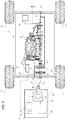
Figure 2 is a schematic representation of the vehicle system ofFigure 1 . - With reference to
Figure 1 , reference numeral 1 is used to indicate a vehicle system, which includes avehicle 2, in particular an agricultural tractor intended for use within a confined building (not shown). - The
vehicle 2 can be advanced along a normal advancing direction, such that thesame vehicle 2 has afront portion 3 and a back portion 4 with respect to the advancing direction. - In
Figure 1 , the advancing direction is represented by a horizontal axis A. - The
vehicle 2 comprises achassis 5 and avehicle body 6 that coats thechassis 5 and accordingly defines an interior and an exterior of thevehicle 2 itself. - The front and the
back portions 3, 4 comprise respectively a front and arear hitch 7, 7r suitable for the attachment of various kinds of respective known agricultural front and rear implements, which are not shown and not described in detail. - As for the front and the rear implements to be used, reference is made, for instance, to standards ISO 8759 and ISO 730, respectively.
- Specifically, the front hitch 7 is a three-point hitch, in particular of the standard type.
- As shown in
Figure 2 , thevehicle 2 further comprises: - an internal combustion engine 8 provided with an
output shaft 9, in particular a crankshaft; - a front power take-off 10 for the further attachment of the implements, such that the latter can be powered;
- a front and a rear pair of
wheels 11; - a first transmission or
joint assembly 12 for transmitting power between theoutput shaft 9 and thewheels 11; and - a second transmission or
joint assembly 13 for transmitting power between theoutput shaft 9 and the front power take-off 10. - Specifically, the front power take-off 10 comprise a power take-
off shaft 14, which partially extends on the inner of thevehicle 2 and externally protrudes from thevehicle body 6 along the advancing direction of thevehicle 2. - Both the first and the
second transmission same output shaft 9, such that the latter can operate as a torque transfer member between the front power take-off 10 and thewheels 11. - For example, the
first transmission 12 is of a known kind and, therefore, is only partially schematized inFigure 2 and not described in further detail. - On the other hand, with greater detail, the
second transmission 13 comprises a gearedtransmission 15 and aclutch 16 selectively connecting the power take-off shaft 14 with theoutput shaft 9 via the gearedtransmission 15. - With the
clutch 16 engaged, the output power from the internal combustion engine 8 is transmitted both to thewheels 11 and to the front power take-off 10, respectively through the first and thesecond transmission clutch 16 disengaged, the same output power is only transmitted to thewheels 11. - In addition, the
vehicle 2 comprises a rear power take-off 17 and vehicle hydraulics 18 (schematically shown inFigure 2 ) that are each connected or can be each connected selectively to theoutput shaft 9, such that the output power from the internal combustion engine 8 may also be transmitted to the rear power take-off 17 and/or supplied to thevehicle hydraulics 18. Both rear power take-off 17 and vehicle hydraulics 18 are known-kind components of thevehicle 2 and are not described, therefore in further detail. - The
vehicle 2 further comprises acontrol unit 20, which is connected to the internal combustion engine 8 to control the latter. Thecontrol unit 20 controls the engine 8, for example based on instructions from a driver of thevehicle 2. - More precisely, the driver depresses an
accelerator pedal 21 being part of thevehicle 2 and being connected to thecontrol unit 20. Thecontrol unit 20 is configured to detect a degree of depression of theaccelerator pedal 21 and, based on the detected degree, to generate an appropriate command for the internal combustion engine 8. - Moreover, the
control unit 20 is connected to theclutch 16 and is configured to command the engagement and the disengagement of theclutch 16 itself, for instance based on instructions from the driver. - In particular, the driver presses a button (not shown) of the
vehicle 2 to request a change in the state of theclutch 16, e.g. from an engaged state to a disengaged state; thecontrol unit 20 is configured to detect the button press and to command theclutch 16 accordingly. - The vehicle system 1 further comprises an
electric power pack 22 that, in the embodiment shown, is arranged on the exterior of thevehicle 2, and is supported by thechassis 5 in a removable manner. - The
electric power pack 22 comprises anexternal box 24 and further comprises, essentially: - a motor-
generator 23; and - an
energy storage unit 25 for storing energy generated by the motor-generator 23 and suppling the energy stored to the motor-generator 23; - Specifically, the
energy storage unit 25 comprises a plurality of battery cells, which are individually connected to the motor-generator 23. - The motor-
generator 23 and theenergy storage unit 25 are housed within theexternal box 24, which is carried by thechassis 5. - The motor-
generator 23 is coupled to the front power take-off 10 in a releasable manner; more precisely, the motor-generator 23 has arotor shaft 26 that is coupled to the front power take-off 10. - Optionally, the motor-
generator 23 comprises a gearbox or aspeed reducer 27, in particular a gear reducer, having an output shaft defined by therotor shaft 26. - In such a manner, a mechanical power outputted by the motor-
generator 23 is transmitted to the front power take-off 10 and then sequentially to theoutput shaft 9 of the internal combustion engine 8 and thewheels 11, respectively through the first andsecond transmissions - Preferably, the mechanical power is also transmitted to the rear power take-
off 18, to supply a possible implement attached thereon, and/or supplied to the vehicle hydraulics 18. - In other words, the motor-
generator 23 can be used to operate the internal combustion engine 8 without supplying the latter with fuel. The use of the motor-generator 23 is intended to replace the use of fuel to drive thewheels 11 and thus thevehicle 2. Therefore, the motor-generator 23 and the internal combustion engine 8 are arranged in a serial fashion. - On one hand, no fuel is supplied to the internal combustion engine 8 when the motor-
generator 23 outputs mechanical power; on the other hand, the motor-generator 23 is exclusively operated as a generator when the internal combustion engine 8 is supplied with fuel. - In the latter situation, the
energy storage unit 25 enjoys the storage of the electric energy produced by the motor-generator 23. - In order to allow the coupling of the
rotor shaft 26 to the power take-offshaft 14, i.e. the coupling between the motor-generator 23 and the front power take-off 10, the vehicle system 1 further comprises a third transmission orjoint assembly 30. - With greater detail, the
third transmission 30 allows the motor-generator 23 to be coupled to the power take-off 10 in a movable manner with respect thereto. - In particular, the
third transmission 30 comprises a double cardan joint 31, which couples therotor shaft 26 and the power take-offshaft 14, preferably in a direct manner. - Conveniently, the
electric power pack 22 and specifically theexternal box 24 are attached to the front hitch 7 in a fixed position and in a detachable manner. The hitch 7 can be raised or lowered, so that theelectric power pack 22 follows the movement of the front hitch 7. - The double cardan joint 31 allows the raising and the lowering of the
electric power pack 22 through the front hitch 7, since allowing the movement of the motor-generator 23 along a rectilinear direction, which is vertical in the embodiment shown, with respect to the front power take-off 10. - In addition, the
electric power pack 22 comprises anothercontrol unit 32, which is connected to the motor-generator 23 and is configured to control the latter for the output of mechanical power or for the generation of energy to be stored. -
Control unit 32 includes anenergy management block 33 connected to theenergy storage unit 25 and configured to monitor or extract information about the actual amount of stored energy, i.e. the actual state of charge of each battery cell. -
Control unit 32 controls the motor-generator 23 also based on the information extracted by theenergy management block 33. -
Control unit 20 of thevehicle 2 is also configured to control the motor-generator 23, in particular independently with respect to the control of the internal combustion engine 8. - Specifically,
control unit 20 controls the motor-generator 23 indirectly viacontrol unit 32. - In other words,
control units generator 23. - For this purpose, the
vehicle 2 is provided e.g. with a not shown command, in particular a lever or a switch, that is connected to controlunit 20 and can be operated by the driver to establish an electric drive mode or a fuel drive mode, in which respectively thevehicle 2 is driven by the motor-generator 23 or the internal combustion engine 8. - When the driver desires to drive the
vehicle 2 by means of the motor-generator 23, namely to establish the electric drive mode, the same driver operates the command accordingly. The same occurs analogously when the driver desires to drive thevehicle 2 by means of the internal combustion engine 8, namely to establish a fuel drive mode. - With the electric drive mode on,
control unit 20 is configured to generate command signals for controlling the motor-generator 23, in particular based on the detected degree of depression of theaccelerator pedal 21. -
Control unit 32 is configured to receive such command signals and then to control the motor-generator 23 directly, but based on the command signals themselves. - The operation of the vehicle system 1 is as follows.
- When the
vehicle 2 is within a confined building, such as a greenhouse or a refrigerating cell, the driver performs the attachment of theelectric power pack 22 to the front hitch 7. - Then, the driver couples the motor-
generator 23 to the front power take-off 10, connects thecontrol units vehicle 2. Here, the driver establishes the electric drive mode through the aforementioned command. - The driver request via the
accelerator pedal 21 is extracted bycontrol unit 20, which generates a command signal for controlling the motor-generator 23 accordingly. - The command signal reaches
control unit 32, which operates the motor-generator 23, to which theenergy storage unit 25 provides the necessary amount of energy. The speed ofoutput shaft 9 is higher that its low-idle speed andcontrol unit 20 inhibits the supply of fuel to the internal combustion engine 8. - The
energy management block 33 identifies the moment in which the energy stored by theenergy storage unit 25 is not sufficient to drive thevehicle 2. In this case,control unit 20 receives a signal fromcontrol unit 32 indicating this insufficiency and automatically establishes the fuel drive mode. Here, the motor-generator 23 is controlled as a generator to recharge theenergy storage unit 25. - In view of the foregoing, the advantages of the vehicle system 1 according to the invention are apparent. The
vehicle 2 can be effectively driven within confined buildings thanks to the use of thepower pack 22, without any emission of pollutants or smells. - Furthermore, since the
output shaft 9 of the internal combustion engine 8 is driven by the front power take-off 10, the lubrication of the internal combustion engine 8 works normally. This allows the internal combustion engine 8 to be promptly turned on; warming-up operations become, therefore, unnecessary, e.g. after a prolonged usage of thevehicle 2 in the electric drive mode. - The
electric power pack 22 is an easy-to-be-replaced external component with respect to thevehicle 2. Therefore, theelectric power pack 22 can be coupled to already existing vehicles without significant adaptations of the same vehicles. In particular, only the vehicle control units have to be reconfigured to control the motor-generator 23, as well as appropriate wirings and network connections should be considered. - The front hitch 7 is particularly appropriate to support the
electric power pack 22, since already designed for supporting heavy implements. The use of the double cardan joint 31 allows the lowering and raising of the front hitch 7 without compromising the connection between the motor-generator 23 and the front power take-off. This helps the driver in the coupling procedures of theelectric power pack 22 to thevehicle 2. - It is clear that modifications can be made to the described vehicle system 1, which do not extend beyond the scope of protection defined by the claims.
- The
electric power pack 22 may be attached to therear hitch 7r, instead of the front hitch 7, and coupled to the rear power take-off 17, instead of the front power take-off 10. - Moreover, the
accelerator pedal 21 may be replaced by any other known device for the same purpose. Connections betweencontrol units - Each of
control units energy management block 33, may be formed by one or more separate and cooperating modules. Two modules are preferred for definingcontrol unit 20. - Eventually, the disclosed transmissions may be constructively different and even consisting of a single joint.
Claims (13)
- A vehicle system including a vehicle (2), the vehicle comprising:- an internal combustion engine (8) provided with an output shaft (9);- a power take-off (10) for the attachment of implements to the vehicle (2);- at least a pair of wheels (11);- first power transmission means (12) configured to allow power transmission between said output shaft (9) and said wheels (11); and- second power transmission means (13) configured to allow power transmission between said output shaft (9) and said power take-off (10);the vehicle system further including an electric power pack (22), which comprises:- a motor-generator (23); and- energy storage means (25) configured to store energy generated by said motor-generator (23) and supply the energy stored to said motor-generator (23);wherein said motor-generator (23) is configured to be coupled to said power take-off (10) in a releasable manner, such that a mechanical output power provided by said motor-generator (23) is transmitted to said output shaft (9) through said second power transmission means (13) and thus to said wheels (11) through said first power transmission means (12).
- The vehicle system of claim 1, further comprising a vehicle control unit (20) configured to independently control said internal combustion engine (8) and said motor-generator (23) .
- The vehicle system of claim 2, wherein said electric power pack (22) further comprises a motor-generator control unit (32) configured to be connected to said vehicle control unit (20) in a releasable manner and to cooperate therewith to control said motor-generator (23).
- The vehicle system of claim 3, wherein said vehicle control unit (20) is configured to control said motor-generator (23) by generating control signals for controlling said motor-generator (23);
said motor-generator control unit (32) being configured to:- receive said control signals from said vehicle control unit (20); and- operating said motor-generator (23) based on said control signals. - The vehicle system of any one of claims from 2 to 4, wherein said vehicle control unit (20) is configured to inhibit fuel supply to said internal combustion engine (8) while controlling said motor-generator (23) to provide mechanical output power.
- The vehicle system of any one of the foregoing claims, further comprising a chassis (5) and a vehicle body (6) coating the chassis (5), so as to define an interior and an exterior of the vehicle (2);
wherein said electric power pack (22) is supported in a removable manner by said chassis (5) on the exterior of the vehicle (2), when said motor-generator (23) is coupled to said power take-off (10). - The vehicle system of any one of the foregoing claims, further comprising a hitch (7), in particular a three-point hitch, which is coupled to said chassis;
said electric power pack (22) being configured to be attached to said hitch in a fixed position and in a detachable manner. - The vehicle system of any one of the foregoing claims, wherein said power take-off (10) is arranged on a front portion of the vehicle (2), according to a normal advancing direction of the vehicle (2).
- The vehicle system of any one of the foregoing claims, wherein said motor-generator (23) is configured to be coupled to said power take-off (10) in a movable manner with respect thereto.
- The vehicle system of claim 9, wherein said motor-generator (23) is configured to be coupled to said power take-off (10) by means of a double cardan joint (31), so as to be movable with respect to said power take-off (10) at least along a rectilinear direction, preferably vertical.
- Use of an electric power pack (22) for driving a vehicle (2), the vehicle (2) comprising:- an internal combustion engine (8) provided with an output shaft (9);- a power take-off (10) for the attachment of implements to the vehicle (2);- at least a pair of wheels (11);- first power transmission means (12) configured to allow power transmission between said output shaft (9) and said wheels (11); and- second power transmission means (13) configured to allow power transmission between said output shaft (9) and said power take-off (10);the electric power pack (22) comprising:- a motor generator (23); and- energy storage means (25) configured to store energy generated by said motor-generator (23) and supply the energy stored to said motor-generator (23);wherein said motor-generator (23) is coupled to said power take-off (10) in a releasable manner, such that a mechanical output power provided by said motor-generator (23) is transmitted to said output shaft (9) through said second power transmission means (13) and thus to said wheels (11) through said first power transmission means (12).
- The use of claim 11, within a confined building.
- A method for powering a vehicle (2) with an electric power pack (22), the vehicle comprising:- an internal combustion engine (8) provided with an output shaft (9);- a power take-off (10) for the attachment of implements to the vehicle (2);- at least a pair of wheels (11);- first power transmission means (12) configured to allow power transmission between said output shaft (9) and said wheels (11); and- second power transmission means (13) configured to allow power transmission between said output shaft (9) and said power take-off (10);the electric power pack (22) comprising:- a motor-generator (23); and- energy storage means (25) configured to store energy generated by said motor-generator (23) and supply the energy stored to said motor-generator (23);the method comprising the step of coupling said motor-generator (23) to said power take-off (10) in a releasable manner, such that a mechanical output power provided by said motor-generator (23) is transmitted to said output shaft (9) through said second power transmission means (13) and thus to said wheels (11) through said first power transmission means (12) .
Applications Claiming Priority (1)
| Application Number | Priority Date | Filing Date | Title |
|---|---|---|---|
| IT102019000013389A IT201900013389A1 (en) | 2019-07-31 | 2019-07-31 | VEHICLE SYSTEM FOR USE IN CLOSED ROOMS |
Publications (2)
| Publication Number | Publication Date |
|---|---|
| EP3771581A1 true EP3771581A1 (en) | 2021-02-03 |
| EP3771581B1 EP3771581B1 (en) | 2023-07-12 |
Family
ID=68733547
Family Applications (1)
| Application Number | Title | Priority Date | Filing Date |
|---|---|---|---|
| EP20188503.5A Active EP3771581B1 (en) | 2019-07-31 | 2020-07-30 | A vehicle system for use in confined buildings |
Country Status (2)
| Country | Link |
|---|---|
| EP (1) | EP3771581B1 (en) |
| IT (1) | IT201900013389A1 (en) |
Cited By (5)
| Publication number | Priority date | Publication date | Assignee | Title |
|---|---|---|---|---|
| IT202100026141A1 (en) * | 2021-10-12 | 2023-04-12 | Cnh Ind Italia Spa | METHOD AND APPARATUS FOR OPERATION OF A WORK VEHICLE |
| WO2023247983A1 (en) * | 2022-06-20 | 2023-12-28 | Christoph Baer | Accumulator-assisted device for tractors |
| JP2024005432A (en) * | 2022-06-30 | 2024-01-17 | 株式会社クボタ | work equipment |
| FR3145898A1 (en) * | 2023-02-21 | 2024-08-23 | Adgero Uk Limited | Hybridization device integrated into a vehicle |
| US20250031593A1 (en) * | 2021-12-06 | 2025-01-30 | The Industry & Academic Cooperation In Chungnam National University (Iac) | Platform structure of electrically-driven tractor |
Citations (4)
| Publication number | Priority date | Publication date | Assignee | Title |
|---|---|---|---|---|
| US20090018716A1 (en) * | 2007-07-12 | 2009-01-15 | Joseph Mario Ambrosio | Parallel hybrid drive system utilizing power take off connection as transfer for a secondary energy source |
| EP2551140A1 (en) * | 2011-07-27 | 2013-01-30 | CLAAS Tractor S.A.S. | Agricultural vehicle and method of operation |
| EP2730444A1 (en) * | 2012-11-09 | 2014-05-14 | MAN Truck & Bus AG | Insert for at least supported driving of a commercial vehicle and/or a commercial vehicle trailer |
| US20150149053A1 (en) * | 2013-11-26 | 2015-05-28 | Deere & Company | Supplemental power attachment for a vehicle |
-
2019
- 2019-07-31 IT IT102019000013389A patent/IT201900013389A1/en unknown
-
2020
- 2020-07-30 EP EP20188503.5A patent/EP3771581B1/en active Active
Patent Citations (4)
| Publication number | Priority date | Publication date | Assignee | Title |
|---|---|---|---|---|
| US20090018716A1 (en) * | 2007-07-12 | 2009-01-15 | Joseph Mario Ambrosio | Parallel hybrid drive system utilizing power take off connection as transfer for a secondary energy source |
| EP2551140A1 (en) * | 2011-07-27 | 2013-01-30 | CLAAS Tractor S.A.S. | Agricultural vehicle and method of operation |
| EP2730444A1 (en) * | 2012-11-09 | 2014-05-14 | MAN Truck & Bus AG | Insert for at least supported driving of a commercial vehicle and/or a commercial vehicle trailer |
| US20150149053A1 (en) * | 2013-11-26 | 2015-05-28 | Deere & Company | Supplemental power attachment for a vehicle |
Cited By (5)
| Publication number | Priority date | Publication date | Assignee | Title |
|---|---|---|---|---|
| IT202100026141A1 (en) * | 2021-10-12 | 2023-04-12 | Cnh Ind Italia Spa | METHOD AND APPARATUS FOR OPERATION OF A WORK VEHICLE |
| US20250031593A1 (en) * | 2021-12-06 | 2025-01-30 | The Industry & Academic Cooperation In Chungnam National University (Iac) | Platform structure of electrically-driven tractor |
| WO2023247983A1 (en) * | 2022-06-20 | 2023-12-28 | Christoph Baer | Accumulator-assisted device for tractors |
| JP2024005432A (en) * | 2022-06-30 | 2024-01-17 | 株式会社クボタ | work equipment |
| FR3145898A1 (en) * | 2023-02-21 | 2024-08-23 | Adgero Uk Limited | Hybridization device integrated into a vehicle |
Also Published As
| Publication number | Publication date |
|---|---|
| IT201900013389A1 (en) | 2021-01-31 |
| EP3771581B1 (en) | 2023-07-12 |
Similar Documents
| Publication | Publication Date | Title |
|---|---|---|
| EP3771581B1 (en) | A vehicle system for use in confined buildings | |
| US8672066B2 (en) | Agricultural vehicle and method of operation | |
| US9845587B2 (en) | Electric drive of mobile apparatus | |
| US20140248992A1 (en) | Engine accessory drive system | |
| EP2891567B1 (en) | Supplemental power attachment for a vehicle | |
| CA2579438A1 (en) | Hybrid vehicle powertrain system with power take-off driven vehicle accessory | |
| EP2253192B1 (en) | Harvester load control system | |
| IT202000013378A1 (en) | TRACKED VEHICLE, METHOD OF CONTROL AND PROGRAM FOR THE ELECTRONIC COMPUTER OF SUCH VEHICLE | |
| JP2008206467A (en) | Combine | |
| US20220134860A1 (en) | Hybrid agricultural vehicle | |
| AU2009356699B2 (en) | Control system for PTO equipment on a vehicle with a hybrid-electric drivetrain | |
| CN112937279A (en) | Hybrid vehicle | |
| CN105857291A (en) | Combined engine and hybrid power system load control | |
| WO2021213354A1 (en) | Range extender, hybrid-power rice transplanter and working method of hybrid-power rice transplanter | |
| KR101315148B1 (en) | Electric vehicle for agriculture and Change of speed controlling methods of Power take off apparatus | |
| WO2014163502A1 (en) | Hybrid power take-off, vehicle provided therewith and method therefor | |
| NL2028626B1 (en) | A utility vehicle and a method of using the utility vehicle | |
| CN209987732U (en) | Range extender, power output system and hybrid tractor | |
| JP2001320805A (en) | Agricultural working machine with hybrid system | |
| JP2026078296A (en) | Work vehicles | |
| CN224130872U (en) | CVT power assembly of efficient tractor | |
| EP4667262A1 (en) | A powertrain for an agricultural tractor with dual drive and dual independent output electrical machine | |
| JP2001169608A (en) | Riding agricultural work machine | |
| CN109649188A (en) | Mixed-power tractor and its energy supply method of adjustment | |
| HRP20221331A1 (en) | HYBRID FOREST TRACTOR-SKIDER |
Legal Events
| Date | Code | Title | Description |
|---|---|---|---|
| PUAI | Public reference made under article 153(3) epc to a published international application that has entered the european phase |
Free format text: ORIGINAL CODE: 0009012 |
|
| STAA | Information on the status of an ep patent application or granted ep patent |
Free format text: STATUS: THE APPLICATION HAS BEEN PUBLISHED |
|
| AK | Designated contracting states |
Kind code of ref document: A1 Designated state(s): AL AT BE BG CH CY CZ DE DK EE ES FI FR GB GR HR HU IE IS IT LI LT LU LV MC MK MT NL NO PL PT RO RS SE SI SK SM TR |
|
| AX | Request for extension of the european patent |
Extension state: BA ME |
|
| STAA | Information on the status of an ep patent application or granted ep patent |
Free format text: STATUS: REQUEST FOR EXAMINATION WAS MADE |
|
| 17P | Request for examination filed |
Effective date: 20210803 |
|
| RBV | Designated contracting states (corrected) |
Designated state(s): AL AT BE BG CH CY CZ DE DK EE ES FI FR GB GR HR HU IE IS IT LI LT LU LV MC MK MT NL NO PL PT RO RS SE SI SK SM TR |
|
| STAA | Information on the status of an ep patent application or granted ep patent |
Free format text: STATUS: EXAMINATION IS IN PROGRESS |
|
| 17Q | First examination report despatched |
Effective date: 20220502 |
|
| RIC1 | Information provided on ipc code assigned before grant |
Ipc: B60W 30/188 20120101ALN20221031BHEP Ipc: B60W 20/40 20160101ALN20221031BHEP Ipc: B60W 20/16 20160101ALN20221031BHEP Ipc: B60K 6/485 20071001ALN20221031BHEP Ipc: B60K 6/48 20071001ALN20221031BHEP Ipc: B60K 6/387 20071001ALN20221031BHEP Ipc: B60K 6/20 20071001ALI20221031BHEP Ipc: B60K 17/34 20060101ALI20221031BHEP Ipc: B60K 17/28 20060101AFI20221031BHEP |
|
| REG | Reference to a national code |
Ref country code: DE Ref legal event code: R079 Free format text: PREVIOUS MAIN CLASS: B60K0006200000 Ipc: B60K0017280000 Ref country code: DE Ref legal event code: R079 Ref document number: 602020013547 Country of ref document: DE Free format text: PREVIOUS MAIN CLASS: B60K0006200000 Ipc: B60K0017280000 |
|
| RIC1 | Information provided on ipc code assigned before grant |
Ipc: B60W 30/188 20120101ALN20221125BHEP Ipc: B60W 20/40 20160101ALN20221125BHEP Ipc: B60W 20/16 20160101ALN20221125BHEP Ipc: B60K 6/485 20071001ALN20221125BHEP Ipc: B60K 6/48 20071001ALN20221125BHEP Ipc: B60K 6/387 20071001ALN20221125BHEP Ipc: B60K 6/20 20071001ALI20221125BHEP Ipc: B60K 17/34 20060101ALI20221125BHEP Ipc: B60K 17/28 20060101AFI20221125BHEP |
|
| RIC1 | Information provided on ipc code assigned before grant |
Ipc: B60W 30/188 20120101ALN20221208BHEP Ipc: B60W 20/40 20160101ALN20221208BHEP Ipc: B60W 20/16 20160101ALN20221208BHEP Ipc: B60K 6/485 20071001ALN20221208BHEP Ipc: B60K 6/48 20071001ALN20221208BHEP Ipc: B60K 6/387 20071001ALN20221208BHEP Ipc: B60K 6/20 20071001ALI20221208BHEP Ipc: B60K 17/34 20060101ALI20221208BHEP Ipc: B60K 17/28 20060101AFI20221208BHEP |
|
| GRAP | Despatch of communication of intention to grant a patent |
Free format text: ORIGINAL CODE: EPIDOSNIGR1 |
|
| STAA | Information on the status of an ep patent application or granted ep patent |
Free format text: STATUS: GRANT OF PATENT IS INTENDED |
|
| INTG | Intention to grant announced |
Effective date: 20230124 |
|
| GRAS | Grant fee paid |
Free format text: ORIGINAL CODE: EPIDOSNIGR3 |
|
| GRAA | (expected) grant |
Free format text: ORIGINAL CODE: 0009210 |
|
| STAA | Information on the status of an ep patent application or granted ep patent |
Free format text: STATUS: THE PATENT HAS BEEN GRANTED |
|
| RAP3 | Party data changed (applicant data changed or rights of an application transferred) |
Owner name: CNH INDUSTRIAL ITALIA S.P.A. |
|
| AK | Designated contracting states |
Kind code of ref document: B1 Designated state(s): AL AT BE BG CH CY CZ DE DK EE ES FI FR GB GR HR HU IE IS IT LI LT LU LV MC MK MT NL NO PL PT RO RS SE SI SK SM TR |
|
| REG | Reference to a national code |
Ref country code: CH Ref legal event code: EP |
|
| REG | Reference to a national code |
Ref country code: IE Ref legal event code: FG4D |
|
| REG | Reference to a national code |
Ref country code: DE Ref legal event code: R096 Ref document number: 602020013547 Country of ref document: DE |
|
| REG | Reference to a national code |
Ref country code: LT Ref legal event code: MG9D |
|
| REG | Reference to a national code |
Ref country code: NL Ref legal event code: MP Effective date: 20230712 |
|
| REG | Reference to a national code |
Ref country code: AT Ref legal event code: MK05 Ref document number: 1586788 Country of ref document: AT Kind code of ref document: T Effective date: 20230712 |
|
| PG25 | Lapsed in a contracting state [announced via postgrant information from national office to epo] |
Ref country code: NL Free format text: LAPSE BECAUSE OF FAILURE TO SUBMIT A TRANSLATION OF THE DESCRIPTION OR TO PAY THE FEE WITHIN THE PRESCRIBED TIME-LIMIT Effective date: 20230712 |
|
| PG25 | Lapsed in a contracting state [announced via postgrant information from national office to epo] |
Ref country code: GR Free format text: LAPSE BECAUSE OF FAILURE TO SUBMIT A TRANSLATION OF THE DESCRIPTION OR TO PAY THE FEE WITHIN THE PRESCRIBED TIME-LIMIT Effective date: 20231013 |
|
| PG25 | Lapsed in a contracting state [announced via postgrant information from national office to epo] |
Ref country code: ES Free format text: LAPSE BECAUSE OF FAILURE TO SUBMIT A TRANSLATION OF THE DESCRIPTION OR TO PAY THE FEE WITHIN THE PRESCRIBED TIME-LIMIT Effective date: 20230712 |
|
| PG25 | Lapsed in a contracting state [announced via postgrant information from national office to epo] |
Ref country code: IS Free format text: LAPSE BECAUSE OF FAILURE TO SUBMIT A TRANSLATION OF THE DESCRIPTION OR TO PAY THE FEE WITHIN THE PRESCRIBED TIME-LIMIT Effective date: 20231112 |
|
| PG25 | Lapsed in a contracting state [announced via postgrant information from national office to epo] |
Ref country code: SE Free format text: LAPSE BECAUSE OF FAILURE TO SUBMIT A TRANSLATION OF THE DESCRIPTION OR TO PAY THE FEE WITHIN THE PRESCRIBED TIME-LIMIT Effective date: 20230712 Ref country code: RS Free format text: LAPSE BECAUSE OF FAILURE TO SUBMIT A TRANSLATION OF THE DESCRIPTION OR TO PAY THE FEE WITHIN THE PRESCRIBED TIME-LIMIT Effective date: 20230712 Ref country code: PT Free format text: LAPSE BECAUSE OF FAILURE TO SUBMIT A TRANSLATION OF THE DESCRIPTION OR TO PAY THE FEE WITHIN THE PRESCRIBED TIME-LIMIT Effective date: 20231113 Ref country code: NO Free format text: LAPSE BECAUSE OF FAILURE TO SUBMIT A TRANSLATION OF THE DESCRIPTION OR TO PAY THE FEE WITHIN THE PRESCRIBED TIME-LIMIT Effective date: 20231012 Ref country code: LV Free format text: LAPSE BECAUSE OF FAILURE TO SUBMIT A TRANSLATION OF THE DESCRIPTION OR TO PAY THE FEE WITHIN THE PRESCRIBED TIME-LIMIT Effective date: 20230712 Ref country code: LT Free format text: LAPSE BECAUSE OF FAILURE TO SUBMIT A TRANSLATION OF THE DESCRIPTION OR TO PAY THE FEE WITHIN THE PRESCRIBED TIME-LIMIT Effective date: 20230712 Ref country code: IS Free format text: LAPSE BECAUSE OF FAILURE TO SUBMIT A TRANSLATION OF THE DESCRIPTION OR TO PAY THE FEE WITHIN THE PRESCRIBED TIME-LIMIT Effective date: 20231112 Ref country code: HR Free format text: LAPSE BECAUSE OF FAILURE TO SUBMIT A TRANSLATION OF THE DESCRIPTION OR TO PAY THE FEE WITHIN THE PRESCRIBED TIME-LIMIT Effective date: 20230712 Ref country code: GR Free format text: LAPSE BECAUSE OF FAILURE TO SUBMIT A TRANSLATION OF THE DESCRIPTION OR TO PAY THE FEE WITHIN THE PRESCRIBED TIME-LIMIT Effective date: 20231013 Ref country code: FI Free format text: LAPSE BECAUSE OF FAILURE TO SUBMIT A TRANSLATION OF THE DESCRIPTION OR TO PAY THE FEE WITHIN THE PRESCRIBED TIME-LIMIT Effective date: 20230712 Ref country code: ES Free format text: LAPSE BECAUSE OF FAILURE TO SUBMIT A TRANSLATION OF THE DESCRIPTION OR TO PAY THE FEE WITHIN THE PRESCRIBED TIME-LIMIT Effective date: 20230712 Ref country code: AT Free format text: LAPSE BECAUSE OF FAILURE TO SUBMIT A TRANSLATION OF THE DESCRIPTION OR TO PAY THE FEE WITHIN THE PRESCRIBED TIME-LIMIT Effective date: 20230712 |
|
| PG25 | Lapsed in a contracting state [announced via postgrant information from national office to epo] |
Ref country code: PL Free format text: LAPSE BECAUSE OF FAILURE TO SUBMIT A TRANSLATION OF THE DESCRIPTION OR TO PAY THE FEE WITHIN THE PRESCRIBED TIME-LIMIT Effective date: 20230712 |
|
| REG | Reference to a national code |
Ref country code: CH Ref legal event code: PL |
|
| REG | Reference to a national code |
Ref country code: BE Ref legal event code: MM Effective date: 20230731 |
|
| PG25 | Lapsed in a contracting state [announced via postgrant information from national office to epo] |
Ref country code: LU Free format text: LAPSE BECAUSE OF NON-PAYMENT OF DUE FEES Effective date: 20230730 |
|
| PG25 | Lapsed in a contracting state [announced via postgrant information from national office to epo] |
Ref country code: LU Free format text: LAPSE BECAUSE OF NON-PAYMENT OF DUE FEES Effective date: 20230730 |
|
| REG | Reference to a national code |
Ref country code: DE Ref legal event code: R097 Ref document number: 602020013547 Country of ref document: DE |
|
| REG | Reference to a national code |
Ref country code: IE Ref legal event code: MM4A |
|
| PG25 | Lapsed in a contracting state [announced via postgrant information from national office to epo] |
Ref country code: SM Free format text: LAPSE BECAUSE OF FAILURE TO SUBMIT A TRANSLATION OF THE DESCRIPTION OR TO PAY THE FEE WITHIN THE PRESCRIBED TIME-LIMIT Effective date: 20230712 Ref country code: RO Free format text: LAPSE BECAUSE OF FAILURE TO SUBMIT A TRANSLATION OF THE DESCRIPTION OR TO PAY THE FEE WITHIN THE PRESCRIBED TIME-LIMIT Effective date: 20230712 Ref country code: EE Free format text: LAPSE BECAUSE OF FAILURE TO SUBMIT A TRANSLATION OF THE DESCRIPTION OR TO PAY THE FEE WITHIN THE PRESCRIBED TIME-LIMIT Effective date: 20230712 Ref country code: DK Free format text: LAPSE BECAUSE OF FAILURE TO SUBMIT A TRANSLATION OF THE DESCRIPTION OR TO PAY THE FEE WITHIN THE PRESCRIBED TIME-LIMIT Effective date: 20230712 Ref country code: CZ Free format text: LAPSE BECAUSE OF FAILURE TO SUBMIT A TRANSLATION OF THE DESCRIPTION OR TO PAY THE FEE WITHIN THE PRESCRIBED TIME-LIMIT Effective date: 20230712 Ref country code: MC Free format text: LAPSE BECAUSE OF FAILURE TO SUBMIT A TRANSLATION OF THE DESCRIPTION OR TO PAY THE FEE WITHIN THE PRESCRIBED TIME-LIMIT Effective date: 20230712 Ref country code: CH Free format text: LAPSE BECAUSE OF NON-PAYMENT OF DUE FEES Effective date: 20230731 Ref country code: SK Free format text: LAPSE BECAUSE OF FAILURE TO SUBMIT A TRANSLATION OF THE DESCRIPTION OR TO PAY THE FEE WITHIN THE PRESCRIBED TIME-LIMIT Effective date: 20230712 |
|
| PLBE | No opposition filed within time limit |
Free format text: ORIGINAL CODE: 0009261 |
|
| STAA | Information on the status of an ep patent application or granted ep patent |
Free format text: STATUS: NO OPPOSITION FILED WITHIN TIME LIMIT |
|
| PG25 | Lapsed in a contracting state [announced via postgrant information from national office to epo] |
Ref country code: BE Free format text: LAPSE BECAUSE OF NON-PAYMENT OF DUE FEES Effective date: 20230731 |
|
| 26N | No opposition filed |
Effective date: 20240415 |
|
| PG25 | Lapsed in a contracting state [announced via postgrant information from national office to epo] |
Ref country code: IE Free format text: LAPSE BECAUSE OF NON-PAYMENT OF DUE FEES Effective date: 20230730 |
|
| PG25 | Lapsed in a contracting state [announced via postgrant information from national office to epo] |
Ref country code: IE Free format text: LAPSE BECAUSE OF NON-PAYMENT OF DUE FEES Effective date: 20230730 Ref country code: SI Free format text: LAPSE BECAUSE OF FAILURE TO SUBMIT A TRANSLATION OF THE DESCRIPTION OR TO PAY THE FEE WITHIN THE PRESCRIBED TIME-LIMIT Effective date: 20230712 |
|
| PG25 | Lapsed in a contracting state [announced via postgrant information from national office to epo] |
Ref country code: BG Free format text: LAPSE BECAUSE OF FAILURE TO SUBMIT A TRANSLATION OF THE DESCRIPTION OR TO PAY THE FEE WITHIN THE PRESCRIBED TIME-LIMIT Effective date: 20230712 |
|
| PG25 | Lapsed in a contracting state [announced via postgrant information from national office to epo] |
Ref country code: BG Free format text: LAPSE BECAUSE OF FAILURE TO SUBMIT A TRANSLATION OF THE DESCRIPTION OR TO PAY THE FEE WITHIN THE PRESCRIBED TIME-LIMIT Effective date: 20230712 |
|
| PG25 | Lapsed in a contracting state [announced via postgrant information from national office to epo] |
Ref country code: CY Free format text: LAPSE BECAUSE OF FAILURE TO SUBMIT A TRANSLATION OF THE DESCRIPTION OR TO PAY THE FEE WITHIN THE PRESCRIBED TIME-LIMIT; INVALID AB INITIO Effective date: 20200730 |
|
| PG25 | Lapsed in a contracting state [announced via postgrant information from national office to epo] |
Ref country code: HU Free format text: LAPSE BECAUSE OF FAILURE TO SUBMIT A TRANSLATION OF THE DESCRIPTION OR TO PAY THE FEE WITHIN THE PRESCRIBED TIME-LIMIT; INVALID AB INITIO Effective date: 20200730 |
|
| PGFP | Annual fee paid to national office [announced via postgrant information from national office to epo] |
Ref country code: DE Payment date: 20250728 Year of fee payment: 6 |
|
| PGFP | Annual fee paid to national office [announced via postgrant information from national office to epo] |
Ref country code: IT Payment date: 20250721 Year of fee payment: 6 |
|
| PGFP | Annual fee paid to national office [announced via postgrant information from national office to epo] |
Ref country code: GB Payment date: 20250722 Year of fee payment: 6 |
|
| PGFP | Annual fee paid to national office [announced via postgrant information from national office to epo] |
Ref country code: FR Payment date: 20250725 Year of fee payment: 6 |
|
| PG25 | Lapsed in a contracting state [announced via postgrant information from national office to epo] |
Ref country code: TR Free format text: LAPSE BECAUSE OF FAILURE TO SUBMIT A TRANSLATION OF THE DESCRIPTION OR TO PAY THE FEE WITHIN THE PRESCRIBED TIME-LIMIT Effective date: 20230712 |