EP3771569A1 - Tape cassette - Google Patents
Tape cassette Download PDFInfo
- Publication number
- EP3771569A1 EP3771569A1 EP20188278.4A EP20188278A EP3771569A1 EP 3771569 A1 EP3771569 A1 EP 3771569A1 EP 20188278 A EP20188278 A EP 20188278A EP 3771569 A1 EP3771569 A1 EP 3771569A1
- Authority
- EP
- European Patent Office
- Prior art keywords
- tape
- cassette
- roll
- tape cassette
- conveying passage
- Prior art date
- Legal status (The legal status is an assumption and is not a legal conclusion. Google has not performed a legal analysis and makes no representation as to the accuracy of the status listed.)
- Granted
Links
Images





Classifications
-
- B—PERFORMING OPERATIONS; TRANSPORTING
- B41—PRINTING; LINING MACHINES; TYPEWRITERS; STAMPS
- B41J—TYPEWRITERS; SELECTIVE PRINTING MECHANISMS, i.e. MECHANISMS PRINTING OTHERWISE THAN FROM A FORME; CORRECTION OF TYPOGRAPHICAL ERRORS
- B41J29/00—Details of, or accessories for, typewriters or selective printing mechanisms not otherwise provided for
- B41J29/12—Guards, shields or dust excluders
- B41J29/13—Cases or covers
-
- B—PERFORMING OPERATIONS; TRANSPORTING
- B41—PRINTING; LINING MACHINES; TYPEWRITERS; STAMPS
- B41J—TYPEWRITERS; SELECTIVE PRINTING MECHANISMS, i.e. MECHANISMS PRINTING OTHERWISE THAN FROM A FORME; CORRECTION OF TYPOGRAPHICAL ERRORS
- B41J15/00—Devices or arrangements of selective printing mechanisms, e.g. ink-jet printers or thermal printers, specially adapted for supporting or handling copy material in continuous form, e.g. webs
- B41J15/04—Supporting, feeding, or guiding devices; Mountings for web rolls or spindles
- B41J15/046—Supporting, feeding, or guiding devices; Mountings for web rolls or spindles for the guidance of continuous copy material, e.g. for preventing skewed conveyance of the continuous copy material
-
- B—PERFORMING OPERATIONS; TRANSPORTING
- B41—PRINTING; LINING MACHINES; TYPEWRITERS; STAMPS
- B41J—TYPEWRITERS; SELECTIVE PRINTING MECHANISMS, i.e. MECHANISMS PRINTING OTHERWISE THAN FROM A FORME; CORRECTION OF TYPOGRAPHICAL ERRORS
- B41J15/00—Devices or arrangements of selective printing mechanisms, e.g. ink-jet printers or thermal printers, specially adapted for supporting or handling copy material in continuous form, e.g. webs
- B41J15/04—Supporting, feeding, or guiding devices; Mountings for web rolls or spindles
- B41J15/044—Cassettes or cartridges containing continuous copy material, tape, for setting into printing devices
-
- B—PERFORMING OPERATIONS; TRANSPORTING
- B41—PRINTING; LINING MACHINES; TYPEWRITERS; STAMPS
- B41J—TYPEWRITERS; SELECTIVE PRINTING MECHANISMS, i.e. MECHANISMS PRINTING OTHERWISE THAN FROM A FORME; CORRECTION OF TYPOGRAPHICAL ERRORS
- B41J2/00—Typewriters or selective printing mechanisms characterised by the printing or marking process for which they are designed
- B41J2/315—Typewriters or selective printing mechanisms characterised by the printing or marking process for which they are designed characterised by selective application of heat to a heat sensitive printing or impression-transfer material
- B41J2/32—Typewriters or selective printing mechanisms characterised by the printing or marking process for which they are designed characterised by selective application of heat to a heat sensitive printing or impression-transfer material using thermal heads
-
- B—PERFORMING OPERATIONS; TRANSPORTING
- B41—PRINTING; LINING MACHINES; TYPEWRITERS; STAMPS
- B41J—TYPEWRITERS; SELECTIVE PRINTING MECHANISMS, i.e. MECHANISMS PRINTING OTHERWISE THAN FROM A FORME; CORRECTION OF TYPOGRAPHICAL ERRORS
- B41J2/00—Typewriters or selective printing mechanisms characterised by the printing or marking process for which they are designed
- B41J2/315—Typewriters or selective printing mechanisms characterised by the printing or marking process for which they are designed characterised by selective application of heat to a heat sensitive printing or impression-transfer material
- B41J2/32—Typewriters or selective printing mechanisms characterised by the printing or marking process for which they are designed characterised by selective application of heat to a heat sensitive printing or impression-transfer material using thermal heads
- B41J2/325—Typewriters or selective printing mechanisms characterised by the printing or marking process for which they are designed characterised by selective application of heat to a heat sensitive printing or impression-transfer material using thermal heads by selective transfer of ink from ink carrier, e.g. from ink ribbon or sheet
-
- B—PERFORMING OPERATIONS; TRANSPORTING
- B41—PRINTING; LINING MACHINES; TYPEWRITERS; STAMPS
- B41J—TYPEWRITERS; SELECTIVE PRINTING MECHANISMS, i.e. MECHANISMS PRINTING OTHERWISE THAN FROM A FORME; CORRECTION OF TYPOGRAPHICAL ERRORS
- B41J3/00—Typewriters or selective printing or marking mechanisms characterised by the purpose for which they are constructed
- B41J3/407—Typewriters or selective printing or marking mechanisms characterised by the purpose for which they are constructed for marking on special material
- B41J3/4078—Printing on textile
-
- B—PERFORMING OPERATIONS; TRANSPORTING
- B41—PRINTING; LINING MACHINES; TYPEWRITERS; STAMPS
- B41J—TYPEWRITERS; SELECTIVE PRINTING MECHANISMS, i.e. MECHANISMS PRINTING OTHERWISE THAN FROM A FORME; CORRECTION OF TYPOGRAPHICAL ERRORS
- B41J32/00—Ink-ribbon cartridges
Definitions
- the present disclosure relates to a tape cassette to be attached to a cassette holder of a printer.
- a regulation guide (a tape lead-out portion) is positioned adjacent to a tape exit of the tape cassette to restrict displacement of the tape in a widthwise direction of the tape (fabric tape) when the tape paid out from a tape roll is conveyed along a conveying passage.
- the regulation guide may not exhibit sufficient function of restricting the displacement of the tape in its widthwise direction due to an employment of a tape having low rigidity or linearity. Therefore, diagonal running of the tape, folding of the tape and wrinkle of the tape may occur.
- the disclosure provides a tape cassette used for a printer including a thermal head and a cassette holder to which the tape cassette is attachable.
- the tape cassette includes a tape roll, a casing, a regulation guide and a pressure member.
- the tape roll is formed by winding a tape.
- the tape has a width defining a widthwise direction.
- the casing accommodates therein the tape roll.
- a tape conveying passage is defined in the casing.
- the regulation guide is positioned at the tape conveying passage to restrict displacement of the tape in the widthwise direction.
- the pressure member is positioned upstream of the regulation guide in a conveying direction of the tape and along the tape conveying passage. The pressure member is in contact with the tape in a contacting direction to apply pressing force to the tape in the contacting direction.
- displacement of the tape in its widthwise direction can be restricted by the regulation guide when the tape paid out from the tape roll is conveyed along the conveying passage.
- the pressure member contacts and presses against the tape.
- a tensile force is applied to the tape conveyed along the conveying passage.
- tape can be conveyed under tension in spite of low rigidity of the tape.
- the regulation guide can exhibit sufficient function of restricting widthwise displacement of the tape, thereby restraining the tape from diagonal moving, folding, and generation of wrinkle at the time of conveyance of the tape.
- the tape can be conveyed under tension in spite of low rigidity of the tape.
- the regulation guide can exhibit sufficient function of restricting widthwise displacement of the tape, thereby restraining the tape from diagonal moving, folding, and generation of wrinkle at the time of conveyance of the tape.
- a tape cartridge according to the present disclosure will be described with reference to accompanying drawings.
- the terms “front”, “rear”, “right”, “left”, “above”, “below”, and the like will be used throughout the description on a basis of Fig. 1 . That is, a diagonal lower left side in Fig. 1 will be referred to as “front side”, a diagonal upper right side in Fig. 1 will be referred to as “rear side”, a diagonal lower right side in Fig. 1 will be referred to as “right side”, and a diagonal upper left side in Fig. 1 will be referred to as “left side” (see also arrows illustrated in each drawing). Further, each component illustrated in the drawings is not to scale for better understanding to the structure.
- the tape printer 1 includes a main body cover 2 where a key board 3 and a liquid crystal display 5 are provided.
- the liquid crystal display 5 is positioned rearward of the key board 3.
- a cover 6 configured to be opened and closed is positioned rearward of the liquid crystal display 5.
- a cartridge receiving portion 8 having a recessed configuration is positioned at an internal space of the main body cover 2.
- the cartridge receiving portion 8 is configured to receive a tape cartridge 30 described later.
- the tape cartridge 30 is an example of a "tape cassette”
- the cartridge receiving portion 8 is an example of a "cassette holder".
- the main body cover 2 has a left rear portion where an ejection slit 9 is formed for ejecting printed fabric tape 153 described later outside of the main body cover 2. Further, the main body cover 2 is formed with a locking hole 7.
- the cover 6 includes a left side wall where an ejection window 11 is formed.
- the cover 6 has a front center portion where a locking protrusion 4 is provided. Upon closure of the cover 6, the locking protrusion 4 is engaged with the locking hole 7.
- a head holder 74, a ribbon take-up shaft 95, and a tape drive shaft 100 are provided in the cartridge receiving portion 8.
- a thermal head 10 including heat generating elements (not illustrated) is mounted on the head holder 74.
- a tape feed motor (not illustrated) including a drive shaft is positioned outside the cartridge receiving portion 8. The drive shaft is drivingly connected to the ribbon take-up shaft 95 and the tape drive shaft 100 through a gear mechanism (not illustrated) including a plurality of gears.
- a roller holder 22 is provided in the cartridge receiving portion 8.
- the roller holder 22 is pivotally movable about an axis of a support shaft m ( Fig. 6 ) by a change-over mechanism (not illustrated) between a printing position illustrated in Figs. 2 and 6 and a release position.
- a platen roller 20 and a conveyer roller 21 are rotatably supported by the roller holder 22.
- a tape cutter mechanism is provided at a cutting position adjacent to the ejection slit 9 for cutting the fabric tape 153 ejected out of the tape cartridge 30 at a predetermined position to provide a printed tape.
- the tape cartridge 30 includes a cartridge case 31 as an example of a "casing".
- the cartridge case 31 includes an upper wall portion 31U, and a lower wall portion 31L.
- a combination of the upper wall portion 31U and the lower wall portion 31L provides a generally box-like configuration having an upper surface 31C, a bottom surface 31A, and a side surface 31B connecting the upper surface 31C to the bottom surface 31A in upward/downward direction.
- the tape cartridge 30 is configured to be inserted into the cartridge receiving portion 8 such that the bottom surface 31A is a leading end for the insertion, and the cartridge receiving portion 8 supports the tape cartridge 30 from below.
- the side surface 31B has a specific area 31Ba formed with a tape discharge opening 49a through which the fabric tape 153 on which an image is printed is configured to be discharged outside the cartridge case 31 such that a widthwise direction of the fabric tape 153 is directed in upward/downward direction.
- the specific area 31Ba is positioned at a most downstream end portion of a tape conveying passage along which the printed fabric tape 153 is conveyed inside the cartridge case 31.
- the cartridge case 31 has a rear left portion where a support hole 65 is formed, and a tape spool 40 is rotatably supported by the support hole 65.
- the fabric tape 153 as an example of "tape” or “fabric tape” is wound over the tape spool 40.
- a combination of the tape spool 40 and the fabric tape 153 wound thereover constitutes a tape roll 206.
- the tape roll 206 has an axis K which is also an axis of the tape spool 40. The axis K extends in upward/downward direction.
- a resin film 207 having a disc shape is positioned between an upper end of the tape roll 206 and a lower surface of the upper wall portion 31U.
- the resin film 207 is in contact with a widthwise edge (specifically an upper edge) of the fabric tape 153 of the tape roll 206.
- a ribbon spool 42 is positioned at a front right internal portion of the cartridge case 31, and an ink ribbon 60 is wound over the ribbon spool 42.
- a combination of the ribbon spool 42 and the ink ribbon 60 wound thereover constitutes a ribbon roll 306 as an example of a "ribbon supply roll.”
- the cartridge case 31 is formed with a support hole 67, and a ribbon take-up spool 44 is rotatably supported by the support hole 67.
- the ribbon take-up spool 44 is at a position between the tape spool 40 and the ribbon spool 42 inside the cartridge case 31.
- the ribbon take-up spool 44 is configured to pull out the ink ribbon 60 from the ribbon spool 42 and to take-up the ink ribbon 60 used for printing.
- a combination of the ribbon take-up spool 44 and the ink ribbon 60 used for printing and taken-up by the ribbon take-up spool 44 constitutes a ribbon take-up roll 307.
- the ribbon take-up shaft 95 is inserted in the ribbon take-up spool 44 to rotate the ribbon take-up spool 44.
- guide portions b1, b2 are provided for regulating a conveying passage of the fabric tape 153 paid out from the tape roll 206, and a guide roller g is provided for regulating a conveying passage of the ink ribbon 60 paid out from the ribbon roll 306.
- An arm portion 34 constitutes a front right portion of the tape cartridge 30.
- the arm portion 34 protrudes frontward from the cartridge case 31, and then is bent at right angle toward a center portion in leftward/rightward direction of the cartridge case 31.
- the fabric tape 153 paid out from the tape roll 206 and moved past the guide portions b1, b2, and the ink ribbon 60 paid out from the ribbon roll 306 and moved past the guide roller g are configured to be guided into an internal space of the arm portion 34.
- a regulation guide 500A (described later) for guiding the fabric tape 153 is provided in the internal space of the arm portion 34.
- a space between the front surface of the cartridge case 31 and a rear surface of the arm portion 34 constitutes a head installing portion 39 where the head holder 74 on which the thermal head 10 is mounted can be positioned when the tape cartridge 30 is attached to the cartridge receiving portion 8.
- a tape lead-out opening 34a is positioned at a tip end portion of the arm portion 34.
- the tape lead-out opening 34a is configured to direct the fabric tape 153 and the ink ribbon 60 positioned close to each other or overlapped with each other toward a head insertion recessed portion DB described later.
- the tape lead-out opening 34a is an example of a "lead-out portion".
- the cartridge case 31 is formed with a support hole at a position downstream of the head installing portion 39 in a conveying direction of the fabric tape 153 and the ink ribbon 60 from the tape lead-out opening 34a of the arm portion 34 to the tape discharge opening 49a.
- a tape drive roller 46 is rotatably supported by the support hole.
- the tape drive shaft 100 is inserted in the tape drive roller 46 to rotate the tape drive roller 46. Further, when the roller holder 22 is changed over to the printing position, the platen roller 20 and the conveyer roller 21 are in pressure contact with the thermal head 10 and the tape drive roller 46, respectively. More specifically, the tape drive roller 46 nips the fabric tape 153 conveyed in leftward/rightward direction in cooperation with the conveyer roller 21 in order to pay out convey the fabric tape 153 from the tape spool 40. Further, the above-described cutter mechanism is positioned at the tape conveying passage and between the tape discharge opening 49a and the ejection slit 9.
- a pair of upper and lower guide members 36 is positioned upstream of the tape drive roller 46.
- the guide members 36 are configured to guide the fabric tape 153 toward the tape discharge opening 49a allowing the fabric tape 153 to pass through between the guide members 36.
- a guide wall 38 extends in upward/downward direction at a position adjacent to the guide members 36.
- the guide wall 38 is configured to position the used ink ribbon 60 conveyed and moved past the head installing portion 39 away from the fabric tape 153 and to guide the fabric tape 153 toward the ribbon take-up spool 44.
- a separation wall 48 extends in upward/downward direction at a position between the guide wall 38 and the ribbon take-up spool 44 so as to prevent the used ink ribbon 60 moved past the guide wall 38 to contact the fabric tape 153 wound over the tape spool 40.
- the tape cartridge 30 has a contact treatment recessed portion D positioned upstream of the tape discharge opening 49a in the conveying passage of the fabric tape 153.
- the contact treatment recessed portion D provides a treatment space for performing conveyance of the fabric tape 153 and printing on the fabric tape 153.
- the contact treatment recessed portion D includes an abutment purpose recessed portion DA and the head insertion recessed portion DB positioned upstream of the abutment purpose recessed portion DA.
- the conveyer roller 21 is movable toward the tape drive roller 46 to convey the fabric tape 153 in the abutment purpose recessed portion DA.
- the thermal head 10 is insertable in the head insertion recessed portion DB.
- the arm portion 34 extends toward the head insertion recessed portion DB.
- the head insertion recessed portion DB is an example of a "recessed portion).
- the tape cartridge 30 also includes a tape insertion portion 49.
- the tape insertion portion 49 has a downstream end in the conveying passage where the above-described tape discharge opening 49a is formed, and has an upstream end in the conveying direction where a tape introduction opening 49b opening to the abutment purpose recessed portion DA is formed.
- the tape insertion portion 49 allows the fabric tape 153 to be inserted therein through the tape introduction opening 49b, and to be discharged outside of the tape cartridge 30 through the tape discharge opening 49a.
- the above-described tape lead-out opening 34a formed in the arm portion 34 is open to the head insertion recessed portion DB.
- the fabric tape 153 paid out from the tape roll 206 and the ink ribbon 60 paid out from the ribbon roll 306 are directed toward the head insertion recessed portion DB through the tape lead-out opening 34a and are exposed to the outside of the cartridge case 31.
- the cartridge case 31 has three corner portions 32 except a corner portion where the tape discharge opening 49a is formed.
- Each of the corner portions 32 functions as a compatible portion 32 having a right-angled corner in plan view and positioned at an intermediate portion in upward/downward direction of the cartridge case 31.
- the cartridge receiving portion 8 has a recessed portion 8a recessed downward in plan view.
- the recessed portion 8a has rounded corners.
- the cartridge receiving portion 8 also has flat surface portions 8b positioned beside each upper end of each rounded corner. Each flat surface portion 8b functions as a cartridge support portion 8b configured to support each compatible portion 32 of the tape cartridge 30 from below.
- the compatible portions 32 When the tape cartridge 30 is inserted into the cartridge receiving portion 8, the compatible portions 32 are supported by the cartridge support portions 8b from below.
- the compatible portions 32 and the cartridge support portions 8b have dimensional relationship with each other so that a widthwise center of the fabric tape 153 supplied from the tape cartridge 30 is generally coincident with a center portion of an array of the heat generating elements in upward/downward direction of the thermal head 10 upon attachment of the tape cartridge 30 to the cartridge receiving portion 8.
- various kinds of tape cartridges 30 are prepared.
- a first kind of the tape cartridge 30 accommodates therein a first kind of fabric tape 153 having a first widthwise length
- a second kind of the tape cartridge 30 accommodates therein a second kind of fabric tape 153 having a second widthwise length different from the first widthwise length.
- the cartridge receiving portion 8 can receive various kinds of the tape cartridges 30 by previously determining dimension of the compatible portions 32 and the like so that the widthwise center of the fabric tape 153 of the attached tape cartridge 30 is generally coincident with the center portion of then array of the heat generating elements.
- the fabric tape 153 is produced by weaving warp extending in a longitudinal direction of the tape and weft extending in a widthwise direction of the tape.
- the fabric tape 153 is produced by satin weave where the warp area appearing on a surface of the fabric tape 153 is greater than weft area as illustrated in Fig. 5A . That is, the warp area exposed to the outside is greater than the weft area exposed to the outside at one of the surfaces of the fabric tape 153 in a thickness direction thereof as illustrated in Fig. 5b .
- the one of the surfaces illustrated in Fig. 4 and 5A of the fabric tape 153 is an image receiving surface 153a on which image is printed.
- the fabric tape 153 is so called seven-harness satin.
- a region of the image receiving surface 153a illustrated in Fig. 5A is a weaving structure including eight warps 1 through 8, and seven wefts 1 through 7 intersecting with each other.
- a conventional calendering treatment is applied to the image receiving surface 153a to enhance print quality.
- such a fabric tape 153 is wound over the tape spool 40 such that the image receiving surface 153a becomes an inner peripheral surface of the rolled tape.
- the platen roller 20 and the conveyer roller 21 are pressed by the thermal head 10 and the tape drive roller 46, respectively as illustrated in Fig. 6 by changing-over the roller holder 22 to the printing position after the tape cartridge 30 is attached to the cartridge receiving portion 8. Accordingly, the conveying passage of the fabric tape 153 has a bent or angled shape by the platen roller 20 facing the thermal head 10 and by the regulation guide 500A positioned in the arm portion 34.
- the ribbon take-up shaft 95 and the tape drive shaft 100 are rotated in synchronism with each other by the driving force of the tape feed motor.
- the rotation of the tape drive shaft 100 causes rotation of the tape drive roller 46, the platen roller 20, and the conveyer roller 21, so that the fabric tape 153 is paid out from the tape roll 206, and is conveyed as in a manner described above.
- the plurality of heat generating elements mounted on the thermal head 10 generate heat, and the ink ribbon 60 is brought into contact with the image receiving surface 153a of the fabric tape 153 by being pressed against the thermal head 10.
- an ink in the ink ribbon 60 is thermally transferred onto the image receiving surface 153a to form a visible ink image on the image receiving surface 153a.
- the fabric tape 153 in which the image is formed is conveyed to the cutting position and is cut by the cutter mechanism. Then the fabric tape 153 is conveyed outside the tape cartridge 30 through the tape discharge opening 49a.
- a separation wall 500 as an example of a first wall is provided inside the arm portion 34 at a position between the conveying passages of the fabric tape 153 and the ink ribbon 60 for separating the fabric tape 153 and the ink ribbon 60 from each other.
- the above-described regulation guide 500A is positioned along the conveying passages and at a downstream end portion of the separation wall 500.
- the separation wall 500 has a front surface 500C.
- the regulation guide 500A is positioned at the tape lead-out opening 34a positioned at the tip end of the arm portion 34.
- the regulation guide 500A extends in the widthwise direction (upward/downward direction) of the tape.
- the regulation guide 500A includes a base portion 500a, an upper guide portion 500b and a lower guide portion 500c.
- the base portion 500a extends in upward/downward direction and protrudes frontward from the front surface 500C of the separation wall 500.
- the upper guide portion 500b extends frontward from one end portion (upper end portion) in the widthwise direction of the base portion 500a.
- the lower guide portion 500c extends frontward from another end portion (lower end portion) in the widthwise direction of the base portion 500a.
- the regulation guide 500A has a generally U-shape.
- the base portion 500a is an example of one of the two protrusions.
- the regulation guide 500A restricts displacement in the widthwise direction (upward/downward direction) of the tape 153 that is conveyed along the conveying passage in the arm portion 34, while the fabric tape 153 passes through a space defined by the base portion 500a, the upper guide portion 500b, and the lower guide portion 500c.
- the regulation guide 500A cannot sufficiently exhibit function of restricting widthwise displacement of the tape, and therefore, it would be difficult to avoid diagonal running of the tape and generation of folding and wrinkle of the tape.
- a film spring 600 ( Fig. 4 ) made from resin is provided in the arm portion 34 at a position upstream of the tape lead-out opening 34a and along the conveying passage of the fabric tape 153.
- the film spring 600 is not delineated in Figs. 6 through 9 to avoid complexity of the drawing.
- the film spring 600 is an example of a pressure member
- the film spring 600 includes a spring body portion 601 and an attachment portion 602 for attaching the spring body portion 601 to the arm portion 34.
- the film spring 600 is positioned frontward of the conveying passage of the fabric tape 153.
- the spring body portion 601 is bent at a bending line 601a to provide a tip end portion 601b positioned leftward of the bending line 601a and a base portion 601c positioned rightward of the bending line 601a.
- the spring body portion 601 protrudes rearward at the bending line 601a.
- the tip end portion 601b and the base portion 601c define therebetween an obtuse angle ⁇ 1 of nearly 180 degrees.
- the arm portion 34 further includes a sloped wall 34c constituting a part of an outline of the arm portion 34, a pawl portion 34b extending leftward in the internal space of the arm portion 34 from the sloped wall 34c, and an engagement protrusion 34d protruding inward and positioned leftward of the sloped wall 34c.
- the engagement protrusion 34d is an example of a "second wall”.
- the attachment portion 602 is bent into V-shape at a bending line 602a. That is, the attachment portion 602 includes a support portion 602b and an engagement portion 602c connected to the support portion 602b at the bending line 602a.
- the support portion 602b is integral with and flush with the base portion 601c of the spring body portion 601.
- the support portion 602b is in abutment with a front surface of the pawl portion 34b.
- the engagement portion 602c extends along an inner surface of the sloped wall 34c, and has a tip end 602d engaged with the engagement protrusion 34d. That is, the engagement protrusion 34d is positioned downstream of the tip end 602d of the engagement portion 602c in the conveying passage of the fabric tape 153 so as to prevent the tip end portion 602d from further moving in downward direction.
- the support portion 602a and the engagement portion 602c define therebetween an acute angle ⁇ 2.
- the attachment portion 602 is forcibly resiliently deformed to reduce the angle ⁇ 2 against inherent urging force of the attachment portion 602.
- a resilient restoration force for increasing the angle ⁇ 2 is applied to the support portion 602 continuous with the spring body portion 601.
- the position of the spring body portion 601 relative to the arm portion 34 is roughly fixed by the abutment between the support portion 602b and the pawl portion 34b.
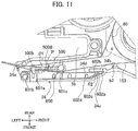
- the resilient restoration force urges the spring body portion 601 rearward (in a direction perpendicular to the surface of the fabric tape 153) to contact the fabric tape 153 conveyed in the arm portion 34. That is the spring body portion 601 applies rearward force to the fabric tape 153 as indicated by an arrow P in Fig. 11 .
- urging force in the direction for contacting the fabric tape 153 is imparted on the film spring 600 by the restoration force of the attachment portion 602.
- the separation wall 500 further includes a guide protrusion 500B protruding frontward from the front surface 500C of the separation wall 500 and positioned upstream of the regulation guide 500A in the conveying direction of the fabric tape 153.
- the guide protrusion 500B is an example of one of the two protrusions.
- the film spring 600 is configured to nip the fabric tape 153 in cooperation with the separation wall 500. Specifically, the bending line 601a and a portion adjacent thereto of the spring body portion 601 contacts the fabric tape 153 at a position between the base portion 500a and the guide protrusion 500B.
- displacement of the fabric tape 153 in its widthwise direction can be restricted by the regulation guide 500A when the fabric tape 153 paid out from the tape roll 206 is conveyed along the conveying passage.
- the film spring 600 contacts and presses against the fabric tape 153 as indicated by the arrow P in Fig. 11 .
- a tensile force is applied to the fabric tape 153 conveyed along the conveying passage.
- the fabric tape 153 can be conveyed under tension in spite of low rigidity of the fabric tape 153.
- the regulation guide 500A can exhibit sufficient function of restricting widthwise displacement of the fabric tape 153.
- the regulation guide 500A has generally U-shape including the upper guide portion 500b, the base portion 500a, and the lower guide portion 500c.
- the tension of the fabric tape 153 is increased, so that the fabric tape 153 can be brought into intimate contact with the base portion 500a during moving past the regulation guide 500A.
- the pressing force from the film spring 600 in the direction of the arrow P also urges the fabric tape 153 toward the base portion 500a. Consequently, the regulating function by means of the upper guide portion 500b and the lower guide portion 500c for restricting widthwise displacement of the fabric tape 153 can be sufficiently exhibited during moving past the regulation guide 500A, thereby restraining the fabric tape 153 from diagonal moving, folding, and generation of wrinkle at the time of conveyance of the fabric tape 153.
- the regulating function of the regulation guide 500A can be promoted by applying tension to the fabric tape 153 in such a manner that the film spring 600 positioned in the arm portion 34 presses against the fabric tape 153 in the direction perpendicular to the surface of the fabric tape 153.
- tensile force is imparted on the fabric tape 153 by the film spring 600, while the fabric tape 153 is nipped between the film spring 600 and the separation wall 500 that is positioned between the conveying passage of the ink ribbon 60 and the conveying passage of the fabric tape 153.
- the regulating function of the separation wall 500 can further be improved.
- the separation wall 500 includes the base portion 500a and the guide protrusion 500B, and the film spring 600 contacts the fabric tape 153 at the position between the base portion 500a and the guide protrusion 500B. Therefore, the fabric tape 153 is conveyed along the meandering passage contacting the guide protrusion 500B, the film spring 600, and the base portion 500a in this order.
- the contacts of the fabric tape 153 with the guide protrusion 500B, the film spring 600, and the base portion 500a and the meandering of the conveying passage can stably impart tension on the fabric tape 153.
- the film spring 600 is set in the arm portion 34 in resiliently deformed state against its natural shape, so that the film spring 600 contacts and presses against the fabric tape 153 by the resilient restoration force of the film spring 600.
- This restoration force can stably apply pressing force to the fabric tape 153.
- the engagement wall 34d is positioned downstream of the tip end 602d of the film spring 600 in the conveying direction of the fabric tape 153. Hence, even though the film spring 600 is urged to be moved toward downstream side in the conveying direction of the fabric tape 153 along with the movement of the fabric tape 153, the engagement wall 34d can prevent the film spring 600 from moving toward the downstream side. Further, displacement of the film spring 600 from its regular position due to user's handling error can also be obviated.
- the fabric has low rigidity or linearity. Hence, deformation or buckling may likely to occur during conveyance of the fabric tape.
- conveyance of the fabric tape 153 can be performed under tension. Thus, regulating effect by the regulation guide 500A can be sufficiently exhibited.
- the conveying passage of the fabric tape 153 is bent by the platen roller 20 and the regulation guide 500A. Since apparent geometrical moment of inertia at the bending portion of the fabric tape 153 increases by the bending of the fabric tape 153 at two locations, tensile force can be securely imparted on the fabric tape 153.
- a tape cartridge 130 according to a second embodiment will be described with reference to Figs. 12 and 13 wherein like parts and components are designated by the same reference numerals as those shown in Figs. 1 through 11 .
- a pressure member for imparting tensile force on the fabric tape 153 is different from the film spring 600 in the first embodiment.
- the film spring 600 is not provided, but instead, elastic members 700A and 700B are provided at a position between the resin film 207 and the upper wall 31U of the cartridge body 31 for applying pressure to the resin film 207.
- the elastic members 700A and 700B will be appropriately collectively described as an elastic member 700.
- the resin film 207 is urged to be in contact with one widthwise end (upper end) of the fabric tape 153 of the tape roll 206 by the elastic member 700, so that resin film 207 presses the fabric tape 153 downward. In other words, pressing force of the resin film 207 against the fabric tape 153 in the widthwise direction thereof is generated by the elastic member 700.
- the elastic member 700 is adhesively fixed to a lower surface of the upper wall 31U, the lower surface facing the resin film 207.
- the elastic member 700 is preferably made from sponge or rubber.
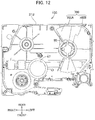
- the elastic members 700A, 700B each having a sector shape are illustrated by a solid line and two dotted chain line in Figs. 12 and 13 , respectively.
- the elastic members 700A and 700B are positioned at diametrically opposite sides with respect to the axis K of the tape roll 206. That is, the elastic member 700A is positioned rearward of the axis K, and the elastic member 700B is positioned frontward of the axis K. Further, at least a part of the elastic member 700 (the elastic member 700A in the second embodiment) contains a portion that presses a part of the resin film 207 at a position superposed with a feed-out portion FO at which the fabric tape 153 is unwound from the tape roll 206. Particularly, the elastic member 700A contains a portion that presses at least a part of the resin film 207 superposed with a tangential line TL at an outer diameter 206d of the tape roll 206.
- the second embodiment exhibits the function the same as that of the first embodiment. That is, displacement of the fabric tape 153 in its widthwise direction can be restricted by the regulation guide 500A when the fabric tape 153 paid out from the tape roll 206 is conveyed along the conveying passage. At this time, the resin film 207 contacts and presses against the fabric tape 153 by the pressing force from the elastic member 700. Hence, a tensile force is applied to the fabric tape 153 conveyed along the conveying passage. Accordingly, the fabric tape 153 can be conveyed under tension in spite of low rigidity of the fabric tape 153. As a result, the regulation guide 500A can exhibit sufficient function of restricting widthwise displacement of the fabric tape 153.
- the regulating function by means of the upper guide portion 500b and the lower guide portion 500c for restricting widthwise displacement of the fabric tape 153 can be sufficiently exhibited during moving past the regulation guide 500A, thereby restraining the fabric tape 153 from diagonal moving, folding, and generation of wrinkle at the time of conveyance of the fabric tape 153, Even though the fabric tape 153 is inherently easily deformed or buckled, the regulating function by the regulation guide 500A can be sufficiently exhibited, since the fabric tape 153 can be conveyed under tension. Further, as described in the first embodiment in connection with Figs. 6 and 7 , the tension can be securely imparted on the fabric tape 153 since the fabric tape 153 is bent along the two locations such as along the platen roller 20 and the regulation guide 500A.
- restricting function of the regulation guide 500A can be sufficiently exhibited, since the resin film 207 is positioned between the tape roll 206 and the cartridge case 31 and presses against the widthwise end of the fabric tape 153 to impart tension on the fabric tape 153.
- sufficient restricting function of the regulation guide 500A can be exhibited.
- the elastic members 700A and 700B are positioned at diametrically opposite sides to each other with respect to the axis K of the tape roll 206. Hence, stabilized pressing force can be applied to the tape roll 206 from the elastic members.
- the elastic member 700 presses against at least the portion of the resin film 207, the portion being overlapped with the feed out portion FO of the fabric tape 153 from the tape roll 206. Therefore, pressing force of the elastic member 700 can be securely applied to the fabric tape 153 fed out to the conveying passage from the tape roll 206.
- the elastic member presses against at least the portion of the resin film 207, the portion being overlapped with a tangential line TL at the outer diameter 206d of the tape roll 206. Therefore, pressing force of the elastic member 700 can be securely applied to the fabric tape 153 fed out to the conveying passage from the tape roll 206.
- the elastic members 700A, 700B may be omitted as long as (a) the resin film 207 is in intimate contact with the upper wall 31U and the widthwise edge of the roll of the fabric tape 153, (b) the resin film 207 has a sufficient elasticity for pressing against the widthwise edge of the roll of the fabric tape 153, and (c) the resin film 207 has a low friction co-efficient with respect to the widthwise edge of the roll of the fabric tape 153.
- the film spring 600 in the first embodiment and the elastic member 700 in the second embodiment may be co-provided in the tape cartridge.
Landscapes
- Engineering & Computer Science (AREA)
- Textile Engineering (AREA)
- Handling Of Continuous Sheets Of Paper (AREA)
- Impression-Transfer Materials And Handling Thereof (AREA)
- Printers Characterized By Their Purpose (AREA)
Abstract
Description
- The present disclosure relates to a tape cassette to be attached to a cassette holder of a printer.
- There has been known a printing technology where a tape cassette is attached to a cassette holder of a printer, and printing is performed on a tape supplied from the tape cassette as described in United States Patent Application Publication No.
2019/0023038 A1 . According to the US Publication, a regulation guide (a tape lead-out portion) is positioned adjacent to a tape exit of the tape cassette to restrict displacement of the tape in a widthwise direction of the tape (fabric tape) when the tape paid out from a tape roll is conveyed along a conveying passage. - However, the regulation guide may not exhibit sufficient function of restricting the displacement of the tape in its widthwise direction due to an employment of a tape having low rigidity or linearity. Therefore, diagonal running of the tape, folding of the tape and wrinkle of the tape may occur.
- In view of the foregoing, it is an object of the disclosure to provide a tape cassette capable of avoiding occurrence of diagonal running of the tape, folding of the tape and wrinkle of the tape even by an employment of the tape having low rigidity.
- In order to attain the above and other objects, according to one aspect, the disclosure provides a tape cassette used for a printer including a thermal head and a cassette holder to which the tape cassette is attachable. The tape cassette includes a tape roll, a casing, a regulation guide and a pressure member. The tape roll is formed by winding a tape. The tape has a width defining a widthwise direction. The casing accommodates therein the tape roll. A tape conveying passage is defined in the casing. The regulation guide is positioned at the tape conveying passage to restrict displacement of the tape in the widthwise direction. The pressure member is positioned upstream of the regulation guide in a conveying direction of the tape and along the tape conveying passage. The pressure member is in contact with the tape in a contacting direction to apply pressing force to the tape in the contacting direction.
- According to one aspect of the present invention, displacement of the tape in its widthwise direction can be restricted by the regulation guide when the tape paid out from the tape roll is conveyed along the conveying passage. At this time, the pressure member contacts and presses against the tape. Hence, a tensile force is applied to the tape conveyed along the conveying passage. Accordingly, tape can be conveyed under tension in spite of low rigidity of the tape. As a result, the regulation guide can exhibit sufficient function of restricting widthwise displacement of the tape, thereby restraining the tape from diagonal moving, folding, and generation of wrinkle at the time of conveyance of the tape.
- According to the present invention, the tape can be conveyed under tension in spite of low rigidity of the tape. As a result, the regulation guide can exhibit sufficient function of restricting widthwise displacement of the tape, thereby restraining the tape from diagonal moving, folding, and generation of wrinkle at the time of conveyance of the tape.
- The particular features and advantages of the embodiment(s) as well as other objects will become apparent from the following description taken in connection with the accompanying drawings, in which:
-
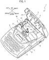
Fig. 1 is a perspective view of a tape printer to which a tape cartridge according to a first embodiment is attached, and particularly illustrating an open state of a cover; -
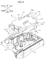
Fig. 2 is a perspective view of the tape cartridge according to the first embodiment and a cartridge receiving portion of the tape printer to which the tape cartridge is attachable; -
Fig. 3 is a plan view of the tape cartridge according to the first embodiment; -
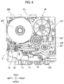
Fig. 4 is a plan view illustrating an internal structure of the tape cartridge with omitting an upper wall of a casing of the cartridge; -
Fig. 5A is an enlarged schematic view illustrating a surface of a fabric tape on which printing is to be performed; -
Fig. 5B is an enlarged cross-sectional view taken along the line V-V inFig. 5A ; -
Fig. 6 is a plan view illustrating the view ofFig. 4 and a structure adjacent to the cartridge receiving portion for description of operation of the tape printer; -
Fig. 7 is an enlarged view of an essential portion illustrated inFig. 6 ; -
Fig. 8A is a perspective view illustrating the internal structure of the tape cartridge with omitting the upper wall of the casing and the tape; -
Fig. 8B is an enlarged view of an essential portion illustrated inFig.8A ; -
Fig. 9A is a perspective view illustrating the view ofFig. 8A and also illustrating the tape; -
Fig. 9B is an enlarged view of an essential portion illustrated inFig.9A ; -
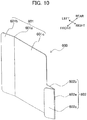
Fig. 10 is a perspective view illustrating a detail of a film spring provided in the tape cartridge according to the first embodiment; -
Fig. 11 is an enlarged view illustrating a structure ambient to the film spring in the tape cartridge according to the first embodiment. -
Fig. 12 is a back-side view of an upper wall of a casing of a tape cartridge according to a second embodiment; and -
Fig. 13 is a plan view illustrating an internal structure of the tape cartridge according to the second embodiment with omitting the upper wall. - Hereinafter, a tape cartridge according to the present disclosure will be described with reference to accompanying drawings. The terms "front", "rear", "right", "left", "above", "below", and the like will be used throughout the description on a basis of
Fig. 1 . That is, a diagonal lower left side inFig. 1 will be referred to as "front side", a diagonal upper right side inFig. 1 will be referred to as "rear side", a diagonal lower right side inFig. 1 will be referred to as "right side", and a diagonal upper left side inFig. 1 will be referred to as "left side" (see also arrows illustrated in each drawing). Further, each component illustrated in the drawings is not to scale for better understanding to the structure. - First, a tape cartridge according to a first embodiment will be described with reference to
Figs. 1 through 11 . - A general structure of a
tape printer 1 to which the tape cartridge is attachable will be described. As illustrated inFig. 1 , thetape printer 1 includes amain body cover 2 where akey board 3 and aliquid crystal display 5 are provided. Theliquid crystal display 5 is positioned rearward of thekey board 3. Acover 6 configured to be opened and closed is positioned rearward of theliquid crystal display 5. Acartridge receiving portion 8 having a recessed configuration is positioned at an internal space of themain body cover 2. Thecartridge receiving portion 8 is configured to receive atape cartridge 30 described later. Thetape cartridge 30 is an example of a "tape cassette", and thecartridge receiving portion 8 is an example of a "cassette holder". - The
main body cover 2 has a left rear portion where an ejection slit 9 is formed for ejecting printedfabric tape 153 described later outside of themain body cover 2. Further, themain body cover 2 is formed with alocking hole 7. Thecover 6 includes a left side wall where anejection window 11 is formed. Thecover 6 has a front center portion where alocking protrusion 4 is provided. Upon closure of thecover 6, thelocking protrusion 4 is engaged with thelocking hole 7. - As illustrated in
Fig. 2 , ahead holder 74, a ribbon take-upshaft 95, and atape drive shaft 100 are provided in thecartridge receiving portion 8. Athermal head 10 including heat generating elements (not illustrated) is mounted on thehead holder 74. A tape feed motor (not illustrated) including a drive shaft is positioned outside thecartridge receiving portion 8. The drive shaft is drivingly connected to the ribbon take-upshaft 95 and thetape drive shaft 100 through a gear mechanism (not illustrated) including a plurality of gears. - Further, a
roller holder 22 is provided in thecartridge receiving portion 8. Theroller holder 22 is pivotally movable about an axis of a support shaft m (Fig. 6 ) by a change-over mechanism (not illustrated) between a printing position illustrated inFigs. 2 and6 and a release position. Aplaten roller 20 and aconveyer roller 21 are rotatably supported by theroller holder 22. - Incidentally, a tape cutter mechanism is provided at a cutting position adjacent to the ejection slit 9 for cutting the
fabric tape 153 ejected out of thetape cartridge 30 at a predetermined position to provide a printed tape. - Next, an internal structure of the
tape cartridge 30 in connection with thecartridge receiving portion 8 will be described with reference toFigs. 2 through 4 . Thetape cartridge 30 includes acartridge case 31 as an example of a "casing". Thecartridge case 31 includes anupper wall portion 31U, and alower wall portion 31L. - A combination of the
upper wall portion 31U and thelower wall portion 31L provides a generally box-like configuration having anupper surface 31C, abottom surface 31A, and aside surface 31B connecting theupper surface 31C to thebottom surface 31A in upward/downward direction. Thetape cartridge 30 is configured to be inserted into thecartridge receiving portion 8 such that thebottom surface 31A is a leading end for the insertion, and thecartridge receiving portion 8 supports thetape cartridge 30 from below. - The
side surface 31B has a specific area 31Ba formed with a tape discharge opening 49a through which thefabric tape 153 on which an image is printed is configured to be discharged outside thecartridge case 31 such that a widthwise direction of thefabric tape 153 is directed in upward/downward direction. The specific area 31Ba is positioned at a most downstream end portion of a tape conveying passage along which the printedfabric tape 153 is conveyed inside thecartridge case 31. - The
cartridge case 31 has a rear left portion where asupport hole 65 is formed, and atape spool 40 is rotatably supported by thesupport hole 65. Thefabric tape 153 as an example of "tape" or "fabric tape" is wound over thetape spool 40. Incidentally, a combination of thetape spool 40 and thefabric tape 153 wound thereover constitutes atape roll 206. Thetape roll 206 has an axis K which is also an axis of thetape spool 40. The axis K extends in upward/downward direction. - A
resin film 207 having a disc shape is positioned between an upper end of thetape roll 206 and a lower surface of theupper wall portion 31U. Theresin film 207 is in contact with a widthwise edge (specifically an upper edge) of thefabric tape 153 of thetape roll 206. - Further, a
ribbon spool 42 is positioned at a front right internal portion of thecartridge case 31, and anink ribbon 60 is wound over theribbon spool 42. A combination of theribbon spool 42 and theink ribbon 60 wound thereover constitutes aribbon roll 306 as an example of a "ribbon supply roll." - The
cartridge case 31 is formed with asupport hole 67, and a ribbon take-upspool 44 is rotatably supported by thesupport hole 67. The ribbon take-upspool 44 is at a position between thetape spool 40 and theribbon spool 42 inside thecartridge case 31. The ribbon take-upspool 44 is configured to pull out theink ribbon 60 from theribbon spool 42 and to take-up theink ribbon 60 used for printing. Incidentally, a combination of the ribbon take-upspool 44 and theink ribbon 60 used for printing and taken-up by the ribbon take-upspool 44 constitutes a ribbon take-up roll 307. - Upon attachment of the
tape cartridge 30 to thecartridge receiving portion 8, the ribbon take-upshaft 95 is inserted in the ribbon take-upspool 44 to rotate the ribbon take-upspool 44. - Inside the
cartridge case 31, guide portions b1, b2 are provided for regulating a conveying passage of thefabric tape 153 paid out from thetape roll 206, and a guide roller g is provided for regulating a conveying passage of theink ribbon 60 paid out from theribbon roll 306. - An
arm portion 34 constitutes a front right portion of thetape cartridge 30. Thearm portion 34 protrudes frontward from thecartridge case 31, and then is bent at right angle toward a center portion in leftward/rightward direction of thecartridge case 31. Thefabric tape 153 paid out from thetape roll 206 and moved past the guide portions b1, b2, and theink ribbon 60 paid out from theribbon roll 306 and moved past the guide roller g are configured to be guided into an internal space of thearm portion 34. In the internal space of thearm portion 34, aregulation guide 500A (described later) for guiding thefabric tape 153 is provided. - A space between the front surface of the
cartridge case 31 and a rear surface of thearm portion 34 constitutes ahead installing portion 39 where thehead holder 74 on which thethermal head 10 is mounted can be positioned when thetape cartridge 30 is attached to thecartridge receiving portion 8. Further, a tape lead-outopening 34a is positioned at a tip end portion of thearm portion 34. The tape lead-outopening 34a is configured to direct thefabric tape 153 and theink ribbon 60 positioned close to each other or overlapped with each other toward a head insertion recessed portion DB described later. The tape lead-outopening 34a is an example of a "lead-out portion". - Further, the
cartridge case 31 is formed with a support hole at a position downstream of thehead installing portion 39 in a conveying direction of thefabric tape 153 and theink ribbon 60 from the tape lead-outopening 34a of thearm portion 34 to thetape discharge opening 49a. Atape drive roller 46 is rotatably supported by the support hole. - Upon attachment of the
tape cartridge 30 to thecartridge receiving portion 8, thetape drive shaft 100 is inserted in thetape drive roller 46 to rotate thetape drive roller 46. Further, when theroller holder 22 is changed over to the printing position, theplaten roller 20 and theconveyer roller 21 are in pressure contact with thethermal head 10 and thetape drive roller 46, respectively. More specifically, thetape drive roller 46 nips thefabric tape 153 conveyed in leftward/rightward direction in cooperation with theconveyer roller 21 in order to pay out convey thefabric tape 153 from thetape spool 40. Further, the above-described cutter mechanism is positioned at the tape conveying passage and between thetape discharge opening 49a and the ejection slit 9. - A pair of upper and
lower guide members 36 is positioned upstream of thetape drive roller 46. Theguide members 36 are configured to guide thefabric tape 153 toward thetape discharge opening 49a allowing thefabric tape 153 to pass through between theguide members 36. - A
guide wall 38 extends in upward/downward direction at a position adjacent to theguide members 36. Theguide wall 38 is configured to position the usedink ribbon 60 conveyed and moved past thehead installing portion 39 away from thefabric tape 153 and to guide thefabric tape 153 toward the ribbon take-upspool 44. Further, aseparation wall 48 extends in upward/downward direction at a position between theguide wall 38 and the ribbon take-upspool 44 so as to prevent the usedink ribbon 60 moved past theguide wall 38 to contact thefabric tape 153 wound over thetape spool 40. - Further, the
tape cartridge 30 has a contact treatment recessed portion D positioned upstream of thetape discharge opening 49a in the conveying passage of thefabric tape 153. The contact treatment recessed portion D provides a treatment space for performing conveyance of thefabric tape 153 and printing on thefabric tape 153. - That is, the contact treatment recessed portion D includes an abutment purpose recessed portion DA and the head insertion recessed portion DB positioned upstream of the abutment purpose recessed portion DA. The
conveyer roller 21 is movable toward thetape drive roller 46 to convey thefabric tape 153 in the abutment purpose recessed portion DA. Thethermal head 10 is insertable in the head insertion recessed portion DB. Thearm portion 34 extends toward the head insertion recessed portion DB. The head insertion recessed portion DB is an example of a "recessed portion). - The
tape cartridge 30 also includes atape insertion portion 49. Thetape insertion portion 49 has a downstream end in the conveying passage where the above-describedtape discharge opening 49a is formed, and has an upstream end in the conveying direction where a tape introduction opening 49b opening to the abutment purpose recessed portion DA is formed. Hence, thetape insertion portion 49 allows thefabric tape 153 to be inserted therein through the tape introduction opening 49b, and to be discharged outside of thetape cartridge 30 through thetape discharge opening 49a. - The above-described tape lead-out
opening 34a formed in thearm portion 34 is open to the head insertion recessed portion DB. Hence, thefabric tape 153 paid out from thetape roll 206 and theink ribbon 60 paid out from theribbon roll 306 are directed toward the head insertion recessed portion DB through the tape lead-outopening 34a and are exposed to the outside of thecartridge case 31. - Further, as illustrated in
Figs. 2 and3 , thecartridge case 31 has threecorner portions 32 except a corner portion where thetape discharge opening 49a is formed. Each of thecorner portions 32 functions as acompatible portion 32 having a right-angled corner in plan view and positioned at an intermediate portion in upward/downward direction of thecartridge case 31. - On the other hand, as illustrated in
Figs. 1 and2 , thecartridge receiving portion 8 has a recessedportion 8a recessed downward in plan view. The recessedportion 8a has rounded corners. Further, thecartridge receiving portion 8 also hasflat surface portions 8b positioned beside each upper end of each rounded corner. Eachflat surface portion 8b functions as acartridge support portion 8b configured to support eachcompatible portion 32 of thetape cartridge 30 from below. - When the
tape cartridge 30 is inserted into thecartridge receiving portion 8, thecompatible portions 32 are supported by thecartridge support portions 8b from below. Thecompatible portions 32 and thecartridge support portions 8b have dimensional relationship with each other so that a widthwise center of thefabric tape 153 supplied from thetape cartridge 30 is generally coincident with a center portion of an array of the heat generating elements in upward/downward direction of thethermal head 10 upon attachment of thetape cartridge 30 to thecartridge receiving portion 8. - Incidentally, various kinds of
tape cartridges 30 are prepared. For example, a first kind of thetape cartridge 30 accommodates therein a first kind offabric tape 153 having a first widthwise length, and a second kind of thetape cartridge 30 accommodates therein a second kind offabric tape 153 having a second widthwise length different from the first widthwise length. Thecartridge receiving portion 8 can receive various kinds of thetape cartridges 30 by previously determining dimension of thecompatible portions 32 and the like so that the widthwise center of thefabric tape 153 of the attachedtape cartridge 30 is generally coincident with the center portion of then array of the heat generating elements. - A structure of the
fabric tape 153 will next be described. Thefabric tape 153 is produced by weaving warp extending in a longitudinal direction of the tape and weft extending in a widthwise direction of the tape. According to the present embodiment, thefabric tape 153 is produced by satin weave where the warp area appearing on a surface of thefabric tape 153 is greater than weft area as illustrated inFig. 5A . That is, the warp area exposed to the outside is greater than the weft area exposed to the outside at one of the surfaces of thefabric tape 153 in a thickness direction thereof as illustrated inFig. 5b . The one of the surfaces illustrated inFig. 4 and5A of thefabric tape 153 is animage receiving surface 153a on which image is printed. - As illustrated in
Figs. 5A and 5B , thefabric tape 153 is so called seven-harness satin. A region of theimage receiving surface 153a illustrated inFig. 5A is a weaving structure including eightwarps ① through ⑧, and sevenwefts ① through ⑦ intersecting with each other. Further, a conventional calendering treatment is applied to theimage receiving surface 153a to enhance print quality. In thetape roll 206 according to the present embodiment, such afabric tape 153 is wound over thetape spool 40 such that theimage receiving surface 153a becomes an inner peripheral surface of the rolled tape. - Operation performed in the
tape printer 1 will be described with reference toFigs. 6 and7 . Theplaten roller 20 and theconveyer roller 21 are pressed by thethermal head 10 and thetape drive roller 46, respectively as illustrated inFig. 6 by changing-over theroller holder 22 to the printing position after thetape cartridge 30 is attached to thecartridge receiving portion 8. Accordingly, the conveying passage of thefabric tape 153 has a bent or angled shape by theplaten roller 20 facing thethermal head 10 and by theregulation guide 500A positioned in thearm portion 34. - The ribbon take-up
shaft 95 and thetape drive shaft 100 are rotated in synchronism with each other by the driving force of the tape feed motor. The rotation of thetape drive shaft 100 causes rotation of thetape drive roller 46, theplaten roller 20, and theconveyer roller 21, so that thefabric tape 153 is paid out from thetape roll 206, and is conveyed as in a manner described above. - At this time, the plurality of heat generating elements mounted on the
thermal head 10 generate heat, and theink ribbon 60 is brought into contact with theimage receiving surface 153a of thefabric tape 153 by being pressed against thethermal head 10. As a result, an ink in theink ribbon 60 is thermally transferred onto theimage receiving surface 153a to form a visible ink image on theimage receiving surface 153a. Thefabric tape 153 in which the image is formed is conveyed to the cutting position and is cut by the cutter mechanism. Then thefabric tape 153 is conveyed outside thetape cartridge 30 through thetape discharge opening 49a. - As illustrated in
Figs. 4 ,8A ,8B ,9A and 9B , aseparation wall 500 as an example of a first wall is provided inside thearm portion 34 at a position between the conveying passages of thefabric tape 153 and theink ribbon 60 for separating thefabric tape 153 and theink ribbon 60 from each other. The above-describedregulation guide 500A is positioned along the conveying passages and at a downstream end portion of theseparation wall 500. Theseparation wall 500 has afront surface 500C. - The
regulation guide 500A is positioned at the tape lead-outopening 34a positioned at the tip end of thearm portion 34. Theregulation guide 500A extends in the widthwise direction (upward/downward direction) of the tape. Theregulation guide 500A includes abase portion 500a, anupper guide portion 500b and alower guide portion 500c. - The
base portion 500a extends in upward/downward direction and protrudes frontward from thefront surface 500C of theseparation wall 500. Theupper guide portion 500b extends frontward from one end portion (upper end portion) in the widthwise direction of thebase portion 500a. Thelower guide portion 500c extends frontward from another end portion (lower end portion) in the widthwise direction of thebase portion 500a. Thus, theregulation guide 500A has a generally U-shape. Thebase portion 500a is an example of one of the two protrusions. - With this structure, the
regulation guide 500A restricts displacement in the widthwise direction (upward/downward direction) of thetape 153 that is conveyed along the conveying passage in thearm portion 34, while thefabric tape 153 passes through a space defined by thebase portion 500a, theupper guide portion 500b, and thelower guide portion 500c. - However, in the
tape cartridge 30, in case of employment of the tape having low rigidity such as thefabric tape 153, theregulation guide 500A cannot sufficiently exhibit function of restricting widthwise displacement of the tape, and therefore, it would be difficult to avoid diagonal running of the tape and generation of folding and wrinkle of the tape. - To this effect, a film spring 600 (
Fig. 4 ) made from resin is provided in thearm portion 34 at a position upstream of the tape lead-outopening 34a and along the conveying passage of thefabric tape 153. Incidentally, thefilm spring 600 is not delineated inFigs. 6 through 9 to avoid complexity of the drawing. Thefilm spring 600 is an example of a pressure member, - As illustrated in
Figs. 10 and11 , thefilm spring 600 includes aspring body portion 601 and anattachment portion 602 for attaching thespring body portion 601 to thearm portion 34. Thefilm spring 600 is positioned frontward of the conveying passage of thefabric tape 153. - The
spring body portion 601 is bent at abending line 601a to provide atip end portion 601b positioned leftward of thebending line 601a and abase portion 601c positioned rightward of thebending line 601a. Thespring body portion 601 protrudes rearward at thebending line 601a. Thetip end portion 601b and thebase portion 601c define therebetween an obtuse angle θ1 of nearly 180 degrees. - As illustrated in
Fig. 11 , thearm portion 34 further includes a slopedwall 34c constituting a part of an outline of thearm portion 34, apawl portion 34b extending leftward in the internal space of thearm portion 34 from the slopedwall 34c, and anengagement protrusion 34d protruding inward and positioned leftward of the slopedwall 34c. Theengagement protrusion 34d is an example of a "second wall". - The
attachment portion 602 is bent into V-shape at abending line 602a. That is, theattachment portion 602 includes asupport portion 602b and anengagement portion 602c connected to thesupport portion 602b at thebending line 602a. Thesupport portion 602b is integral with and flush with thebase portion 601c of thespring body portion 601. Thesupport portion 602b is in abutment with a front surface of thepawl portion 34b. - The
engagement portion 602c extends along an inner surface of the slopedwall 34c, and has atip end 602d engaged with theengagement protrusion 34d. That is, theengagement protrusion 34d is positioned downstream of thetip end 602d of theengagement portion 602c in the conveying passage of thefabric tape 153 so as to prevent thetip end portion 602d from further moving in downward direction. - In a state illustrated in
Fig. 11 , thesupport portion 602a and theengagement portion 602c define therebetween an acute angle θ2. Further, theattachment portion 602 is forcibly resiliently deformed to reduce the angle θ2 against inherent urging force of theattachment portion 602. As a result, a resilient restoration force for increasing the angle θ2 is applied to thesupport portion 602 continuous with thespring body portion 601. At this time, the position of thespring body portion 601 relative to thearm portion 34 is roughly fixed by the abutment between thesupport portion 602b and thepawl portion 34b. - Further, the resilient restoration force urges the
spring body portion 601 rearward (in a direction perpendicular to the surface of the fabric tape 153) to contact thefabric tape 153 conveyed in thearm portion 34. That is thespring body portion 601 applies rearward force to thefabric tape 153 as indicated by an arrow P inFig. 11 . In other words, urging force in the direction for contacting thefabric tape 153 is imparted on thefilm spring 600 by the restoration force of theattachment portion 602. - Further, the
separation wall 500 further includes aguide protrusion 500B protruding frontward from thefront surface 500C of theseparation wall 500 and positioned upstream of theregulation guide 500A in the conveying direction of thefabric tape 153. Theguide protrusion 500B is an example of one of the two protrusions. Thefilm spring 600 is configured to nip thefabric tape 153 in cooperation with theseparation wall 500. Specifically, thebending line 601a and a portion adjacent thereto of thespring body portion 601 contacts thefabric tape 153 at a position between thebase portion 500a and theguide protrusion 500B. - According to the above-described first embodiment, displacement of the
fabric tape 153 in its widthwise direction can be restricted by theregulation guide 500A when thefabric tape 153 paid out from thetape roll 206 is conveyed along the conveying passage. At this time, thefilm spring 600 contacts and presses against thefabric tape 153 as indicated by the arrow P inFig. 11 . Hence, a tensile force is applied to thefabric tape 153 conveyed along the conveying passage. Accordingly, thefabric tape 153 can be conveyed under tension in spite of low rigidity of thefabric tape 153. As a result, theregulation guide 500A can exhibit sufficient function of restricting widthwise displacement of thefabric tape 153. - Specifically, as described in connection with
Figs. 8 and9 , theregulation guide 500A has generally U-shape including theupper guide portion 500b, thebase portion 500a, and thelower guide portion 500c. On a basis of positional relationship between theregulation guide 500A and the conveying passage of thefabric tape 153 extending from thetape roll 206 as illustrated inFigs. 4 ,6 ,9A and 9B , the tension of thefabric tape 153 is increased, so that thefabric tape 153 can be brought into intimate contact with thebase portion 500a during moving past theregulation guide 500A. - Further, the pressing force from the
film spring 600 in the direction of the arrow P also urges thefabric tape 153 toward thebase portion 500a. Consequently, the regulating function by means of theupper guide portion 500b and thelower guide portion 500c for restricting widthwise displacement of thefabric tape 153 can be sufficiently exhibited during moving past theregulation guide 500A, thereby restraining thefabric tape 153 from diagonal moving, folding, and generation of wrinkle at the time of conveyance of thefabric tape 153. - Particularly, the regulating function of the
regulation guide 500A can be promoted by applying tension to thefabric tape 153 in such a manner that thefilm spring 600 positioned in thearm portion 34 presses against thefabric tape 153 in the direction perpendicular to the surface of thefabric tape 153. - Particularly, tensile force is imparted on the
fabric tape 153 by thefilm spring 600, while thefabric tape 153 is nipped between thefilm spring 600 and theseparation wall 500 that is positioned between the conveying passage of theink ribbon 60 and the conveying passage of thefabric tape 153. Hence, the regulating function of theseparation wall 500 can further be improved. - Particularly, the
separation wall 500 includes thebase portion 500a and theguide protrusion 500B, and thefilm spring 600 contacts thefabric tape 153 at the position between thebase portion 500a and theguide protrusion 500B. Therefore, thefabric tape 153 is conveyed along the meandering passage contacting theguide protrusion 500B, thefilm spring 600, and thebase portion 500a in this order. The contacts of thefabric tape 153 with theguide protrusion 500B, thefilm spring 600, and thebase portion 500a and the meandering of the conveying passage can stably impart tension on thefabric tape 153. - Particularly, the
film spring 600 is set in thearm portion 34 in resiliently deformed state against its natural shape, so that thefilm spring 600 contacts and presses against thefabric tape 153 by the resilient restoration force of thefilm spring 600. This restoration force can stably apply pressing force to thefabric tape 153. - Particularly, the
engagement wall 34d is positioned downstream of thetip end 602d of thefilm spring 600 in the conveying direction of thefabric tape 153. Hence, even though thefilm spring 600 is urged to be moved toward downstream side in the conveying direction of thefabric tape 153 along with the movement of thefabric tape 153, theengagement wall 34d can prevent thefilm spring 600 from moving toward the downstream side. Further, displacement of thefilm spring 600 from its regular position due to user's handling error can also be obviated. - Generally, the fabric has low rigidity or linearity. Hence, deformation or buckling may likely to occur during conveyance of the fabric tape. However, in the
tape cartridge 30 according to the first embodiment, conveyance of thefabric tape 153 can be performed under tension. Thus, regulating effect by theregulation guide 500A can be sufficiently exhibited. - Particularly, as illustrated in
Figs. 6 and7 , after attachment of thetape cartridge 30 to thecartridge receiving portion 8, the conveying passage of thefabric tape 153 is bent by theplaten roller 20 and theregulation guide 500A. Since apparent geometrical moment of inertia at the bending portion of thefabric tape 153 increases by the bending of thefabric tape 153 at two locations, tensile force can be securely imparted on thefabric tape 153. - Next, a
tape cartridge 130 according to a second embodiment will be described with reference toFigs. 12 and13 wherein like parts and components are designated by the same reference numerals as those shown inFigs. 1 through 11 . In the second embodiment, a pressure member for imparting tensile force on thefabric tape 153 is different from thefilm spring 600 in the first embodiment. - As illustrated in
Figs. 12 and13 , in thetape cartridge 130 according to the second embodiment, thefilm spring 600 is not provided, but instead,elastic members resin film 207 and theupper wall 31U of thecartridge body 31 for applying pressure to theresin film 207. Theelastic members elastic member 700. Specifically, theresin film 207 is urged to be in contact with one widthwise end (upper end) of thefabric tape 153 of thetape roll 206 by theelastic member 700, so thatresin film 207 presses thefabric tape 153 downward. In other words, pressing force of theresin film 207 against thefabric tape 153 in the widthwise direction thereof is generated by theelastic member 700. - The
elastic member 700 is adhesively fixed to a lower surface of theupper wall 31U, the lower surface facing theresin film 207. Theelastic member 700 is preferably made from sponge or rubber. Theelastic members Figs. 12 and13 , respectively. - As illustrated in
Figs. 12 and13 , theelastic members tape roll 206. That is, theelastic member 700A is positioned rearward of the axis K, and theelastic member 700B is positioned frontward of the axis K. Further, at least a part of the elastic member 700 (theelastic member 700A in the second embodiment) contains a portion that presses a part of theresin film 207 at a position superposed with a feed-out portion FO at which thefabric tape 153 is unwound from thetape roll 206. Particularly, theelastic member 700A contains a portion that presses at least a part of theresin film 207 superposed with a tangential line TL at anouter diameter 206d of thetape roll 206. - The second embodiment exhibits the function the same as that of the first embodiment. That is, displacement of the
fabric tape 153 in its widthwise direction can be restricted by theregulation guide 500A when thefabric tape 153 paid out from thetape roll 206 is conveyed along the conveying passage. At this time, theresin film 207 contacts and presses against thefabric tape 153 by the pressing force from theelastic member 700. Hence, a tensile force is applied to thefabric tape 153 conveyed along the conveying passage. Accordingly, thefabric tape 153 can be conveyed under tension in spite of low rigidity of thefabric tape 153. As a result, theregulation guide 500A can exhibit sufficient function of restricting widthwise displacement of thefabric tape 153. - As a result, the regulating function by means of the
upper guide portion 500b and thelower guide portion 500c for restricting widthwise displacement of thefabric tape 153 can be sufficiently exhibited during moving past theregulation guide 500A, thereby restraining thefabric tape 153 from diagonal moving, folding, and generation of wrinkle at the time of conveyance of thefabric tape 153, Even though thefabric tape 153 is inherently easily deformed or buckled, the regulating function by theregulation guide 500A can be sufficiently exhibited, since thefabric tape 153 can be conveyed under tension. Further, as described in the first embodiment in connection withFigs. 6 and7 , the tension can be securely imparted on thefabric tape 153 since thefabric tape 153 is bent along the two locations such as along theplaten roller 20 and theregulation guide 500A. - Particularly, in the second embodiment, restricting function of the
regulation guide 500A can be sufficiently exhibited, since theresin film 207 is positioned between thetape roll 206 and thecartridge case 31 and presses against the widthwise end of thefabric tape 153 to impart tension on thefabric tape 153. - Particularly, in the second embodiment, the
elastic member 700A positioned between theresin film 207 and thecartridge case 31 presses against theresin film 207, so that the pressure from theelastic member 700A is applied to the widthwise end of thefabric tape 153 through theresin film 207, thereby generating sufficient tension in thefabric tape 153. Hence, sufficient restricting function of theregulation guide 500A can be exhibited. - Particularly, in the second embodiment, the
elastic members tape roll 206. Hence, stabilized pressing force can be applied to thetape roll 206 from the elastic members. - Particularly, in the second embodiment, the
elastic member 700 presses against at least the portion of theresin film 207, the portion being overlapped with the feed out portion FO of thefabric tape 153 from thetape roll 206. Therefore, pressing force of theelastic member 700 can be securely applied to thefabric tape 153 fed out to the conveying passage from thetape roll 206. - Particularly, in the second embodiment, the elastic member presses against at least the portion of the
resin film 207, the portion being overlapped with a tangential line TL at theouter diameter 206d of thetape roll 206. Therefore, pressing force of theelastic member 700 can be securely applied to thefabric tape 153 fed out to the conveying passage from thetape roll 206. - In the second embodiment, the
elastic members resin film 207 is in intimate contact with theupper wall 31U and the widthwise edge of the roll of thefabric tape 153, (b) theresin film 207 has a sufficient elasticity for pressing against the widthwise edge of the roll of thefabric tape 153, and (c) theresin film 207 has a low friction co-efficient with respect to the widthwise edge of the roll of thefabric tape 153. - In the above-description, the terms "vertical", "parallel", and "flat", and the like are not in the narrowest sense. That is, production tolerance and manufacturing error are inclusive in these terms, and thus, "substantially vertical" "substantially parallel" and "substantially flat" are also within the meaning of these terms.
- In the above description, the terms "identical", "equal", "different" and the like with respect to dimension and size are not in the narrowest sense. Production tolerance and manufacturing error are inclusive in these terms, and thus, "substantially identical", "substantially equal", and "substantially different" are also within the meaning of these terms.
- While the description has been made in detail with reference to the specific embodiments, it would be apparent to those skilled in the art that various changes and modifications may be made without departing from the scope of the disclosure. For example, the
film spring 600 in the first embodiment and theelastic member 700 in the second embodiment may be co-provided in the tape cartridge.
Claims (14)
- A tape cassette (10) used for a printer (1) including a thermal head (10) and a cassette holder (8) to which the tape cassette is attachable, the tape cassette comprising;
a tape roll (206) formed by winding a tape (153), the tape having a width defining a widthwise direction;
a casing (31) accommodating therein the tape roll, a tape conveying passage being defined in the casing;
a regulation guide (500A) positioned at the tape conveying passage to restrict displacement of the tape in the widthwise direction; and
a pressure member (600, 207, 700A, 700B) positioned upstream of the regulation guide in a conveying direction of the tape and along the tape conveying passage, the pressure member being in contact with the tape in a contacting direction to apply pressing force to the tape in the contacting direction. - The tape cassette (10) according to claim 1, wherein the casing has a recessed portion (DB) in which the thermal head is inserted upon attachment of the tape cassette to the cassette holder,
wherein the tape cassette further comprises an arm portion (34) extending toward the recessed portion, the arm portion comprising a tape lead-out portion (34a) through which the tape is directed toward the recessed portion,
wherein the regulation guide (500A) is positioned at the tape lead-out portion, and
wherein the pressure member (600) is positioned in the arm portion and along the tape conveying passage at a position upstream of the tape lead-out portion in the conveying direction of the tape, the contacting direction being perpendicular to a surface of the tape. - The tape cassette (10) according to claim 2, further comprising:a ribbon roll (306) accommodated in the casing and formed by winding an ink ribbon (60), an ink contained in the ink ribbon being transferred to the fabric tape in the recessed portion upon application of heat from the thermal head, the ink ribbon being conveyed along an ink ribbon conveying passage;a ribbon take-up roll (307) accommodated in the casing and formed by taking up the ink ribbon from which the ink is transferred; anda first wall (500) positioned in the arm portion and between the tape conveying passage and the ink ribbon conveying passage,wherein the pressure member (600) is positioned in the arm portion and nips the tape in cooperation with the first wall.
- The tape cassette (10) according to claim 3, wherein the first wall includes two protrusions (500a, 500B), and
wherein the pressure member (600) contacts the tape at a position between the two protrusions. - The tape cassette (10) according to any one of claims 2 to 4, wherein the pressure member (600) is a resilient resin film set in the arm portion in a forcibly resiliently deformed state, the resilient resin film having a resilient restoration force to contact and press against the tape.
- The tape cassette (10) according to any one of claims 2 to 5, wherein the pressure member has one end (602d), and
wherein the tape cassette further comprises a second wall (34d) positioned in the arm portion at a position downstream of the one end of the pressure member in the conveying direction to prevent the pressure member from moving in a downstream direction. - The tape cassette (10) according to claim 1, wherein the pressure member comprises a resin film (207) positioned between the tape roll and the casing, and in pressure contact with a widthwise edge of the tape.
- The tape cassette (10) according to claim 7, wherein the pressure member further comprises an elastic member (700A, 700B) positioned between the resin film and the casing to elastically urge the resin film in the contacting direction toward the widthwise edge of the tape.
- The tape cassette (10) according to claim 8, wherein the elastic member is adhesively fixed to a surface of the casing, the surface facing the resin film.
- The tape cassette (10) according to claim 8 or 9, wherein the elastic member comprises a first elastic member (700A) and a second elastic member (700B) positioned at a position diametrically opposite to the first elastic member with respect to an axis (K) of the tape roll.
- The tape cassette (10) according to any one of claims 8 to 10, wherein the tape roll has a feed-out portion (FO) at which the tape is fed out from the tape roll toward the tape conveying passage, and
wherein the elastic member presses against at least a portion of the resin film at a position corresponding to the feed-out portion. - The tape cassette (10) according to any one of claims 8 to 10, wherein the elastic member presses against at least a portion of the resin film at a position corresponding to a tangential line at an outer diameter of the tape roll.
- The tape cassette (10) according to any one of claims 1 to 12, wherein the tape is a fabric tape.
- The tape cassette (10) according to any one of claims 1 to 13, wherein the tape printer includes a platen roller (20) facing the thermal head when the tape cassette is attached to the cassette holder, and
wherein the tape conveying passage is bent at the platen roller and at the regulation guide.
Applications Claiming Priority (1)
| Application Number | Priority Date | Filing Date | Title |
|---|---|---|---|
| JP2019141362A JP7389963B2 (en) | 2019-07-31 | 2019-07-31 | tape cassette |
Publications (2)
| Publication Number | Publication Date |
|---|---|
| EP3771569A1 true EP3771569A1 (en) | 2021-02-03 |
| EP3771569B1 EP3771569B1 (en) | 2022-12-07 |
Family
ID=71846225
Family Applications (1)
| Application Number | Title | Priority Date | Filing Date |
|---|---|---|---|
| EP20188278.4A Active EP3771569B1 (en) | 2019-07-31 | 2020-07-29 | Tape cassette |
Country Status (4)
| Country | Link |
|---|---|
| US (1) | US11760115B2 (en) |
| EP (1) | EP3771569B1 (en) |
| JP (1) | JP7389963B2 (en) |
| CN (1) | CN112297660B (en) |
Citations (3)
| Publication number | Priority date | Publication date | Assignee | Title |
|---|---|---|---|---|
| US5188469A (en) * | 1988-10-14 | 1993-02-23 | Brother Kogyo Kabushiki Kaisha | Tape feed cassette with tape cutter and guide |
| CN1135417A (en) * | 1995-03-29 | 1996-11-13 | 兄弟工业株式会社 | Combo box including one tape cassette and one ribbon cassette |
| US20190023038A1 (en) | 2016-03-25 | 2019-01-24 | Brother Kogyo Kabushiki Kaisha | Tape cartridge with improved running stability when conveying fabric tape |
Family Cites Families (20)
| Publication number | Priority date | Publication date | Assignee | Title |
|---|---|---|---|---|
| SE364584B (en) * | 1970-04-13 | 1974-02-25 | Canon Kk | |
| JPS5656453A (en) * | 1979-10-16 | 1981-05-18 | Ricoh Co Ltd | Ribbon tension controller for ribbon cartridge |
| EP0090164A3 (en) * | 1982-03-23 | 1983-12-14 | Franz Büttner AG | Winding device for a ribbon cartridge in a printer |
| US4966476A (en) * | 1987-12-29 | 1990-10-30 | Brother Kogyo Kabushiki Kaisha | Tape printer |
| JPH02106555A (en) * | 1988-10-14 | 1990-04-18 | Brother Ind Ltd | Tape containing cassette |
| US5685654A (en) | 1988-10-14 | 1997-11-11 | Brother Kogyo Kabushiki Kaisha | Printing tape cassette with separated recording medium and ink ribbon |
| JPH0743079Y2 (en) * | 1988-10-19 | 1995-10-04 | ブラザー工業株式会社 | Tape matching and crimping device |
| EP0869009A3 (en) * | 1997-03-31 | 1999-11-10 | Victor Company Of Japan, Limited | Improved structure of inked ribbon cartridge and thermal transfer color printer |
| US6135657A (en) * | 1998-08-07 | 2000-10-24 | Axiohm Transaction Solutions, Inc. | Ribbon cassette with coaxial spools on common shaft with partition for preventing contamination |
| JP2000108471A (en) | 1998-10-05 | 2000-04-18 | Fujicopian Co Ltd | Ink ribbon cassette |
| JP4543601B2 (en) * | 1999-08-06 | 2010-09-15 | ブラザー工業株式会社 | Tape supply cartridge |
| JP2003285522A (en) * | 2002-03-27 | 2003-10-07 | Brother Ind Ltd | cassette |
| JP4947085B2 (en) | 2009-03-31 | 2012-06-06 | ブラザー工業株式会社 | Tape cassette |
| CN101850662B (en) | 2009-03-31 | 2015-02-11 | 兄弟工业株式会社 | Tape printing apparatus |
| JP5445582B2 (en) | 2009-03-31 | 2014-03-19 | ブラザー工業株式会社 | Tape cassette |
| JP5212550B2 (en) * | 2009-12-16 | 2013-06-19 | ブラザー工業株式会社 | Tape cassette |
| US9550381B2 (en) * | 2013-04-15 | 2017-01-24 | Brother Kogyo Kabushiki Kaisha | Tape cassette |
| JP6113207B2 (en) * | 2014-03-24 | 2017-04-12 | セイコーエプソン株式会社 | Tape cartridge |
| JP6439615B2 (en) * | 2015-07-13 | 2018-12-19 | ブラザー工業株式会社 | Ribbon cassette |
| JP6530105B2 (en) * | 2018-05-07 | 2019-06-12 | セイコーエプソン株式会社 | Tape cartridge |
-
2019
- 2019-07-31 JP JP2019141362A patent/JP7389963B2/en active Active
-
2020
- 2020-07-29 EP EP20188278.4A patent/EP3771569B1/en active Active
- 2020-07-29 US US16/941,807 patent/US11760115B2/en active Active
- 2020-07-30 CN CN202010748984.7A patent/CN112297660B/en active Active
Patent Citations (4)
| Publication number | Priority date | Publication date | Assignee | Title |
|---|---|---|---|---|
| US5188469A (en) * | 1988-10-14 | 1993-02-23 | Brother Kogyo Kabushiki Kaisha | Tape feed cassette with tape cutter and guide |
| CN1135417A (en) * | 1995-03-29 | 1996-11-13 | 兄弟工业株式会社 | Combo box including one tape cassette and one ribbon cassette |
| US20190023038A1 (en) | 2016-03-25 | 2019-01-24 | Brother Kogyo Kabushiki Kaisha | Tape cartridge with improved running stability when conveying fabric tape |
| EP3434493A1 (en) * | 2016-03-25 | 2019-01-30 | Brother Kogyo Kabushiki Kaisha | Tape cartridge |
Also Published As
| Publication number | Publication date |
|---|---|
| JP2021024121A (en) | 2021-02-22 |
| CN112297660B (en) | 2024-09-13 |
| JP7389963B2 (en) | 2023-12-01 |
| CN112297660A (en) | 2021-02-02 |
| EP3771569B1 (en) | 2022-12-07 |
| US20210031546A1 (en) | 2021-02-04 |
| US11760115B2 (en) | 2023-09-19 |
Similar Documents
| Publication | Publication Date | Title |
|---|---|---|
| JP6453977B2 (en) | Media processing apparatus with improved media and ribbon loading and unloading characteristics | |
| JP4561442B2 (en) | Tape cassette | |
| CN101850663B (en) | with box | |
| EP0364305A2 (en) | Tape feed mechanism | |
| KR102580618B1 (en) | Ribbon cartridge and printing device | |
| JPH01122870A (en) | Device for transferring the film from the support sheet to the substrate | |
| TWI727291B (en) | Ribbon cassette and printing device | |
| TWI706868B (en) | Printing cassette, belt guide and printing device | |
| TWI767171B (en) | cassette | |
| US11117406B2 (en) | Tape printing device and cartridge set | |
| US4343556A (en) | Ink ribbon cartridge | |
| EP3771569B1 (en) | Tape cassette | |
| GB2141073A (en) | Ink ribbon feeding mechanism | |
| US20070290433A1 (en) | Paper feed cassette | |
| JP4162006B2 (en) | Paper feeder | |
| JP7356643B2 (en) | tape cassette | |
| US7552920B2 (en) | Paper feed cassette | |
| JP4461675B2 (en) | Transfer head structure of transfer tool and transfer tool | |
| US20220111670A1 (en) | Cartridge | |
| JP7782539B2 (en) | Tape cartridge and method of manufacturing the tape cartridge | |
| CN111376621A (en) | Assembly with printing unit and box | |
| JP7819475B2 (en) | tape cassette | |
| JP2003136821A (en) | Printer | |
| JP2022101043A (en) | Tape cartridge | |
| JPH06227073A (en) | Print medium feeding device |
Legal Events
| Date | Code | Title | Description |
|---|---|---|---|
| PUAI | Public reference made under article 153(3) epc to a published international application that has entered the european phase |
Free format text: ORIGINAL CODE: 0009012 |
|
| STAA | Information on the status of an ep patent application or granted ep patent |
Free format text: STATUS: THE APPLICATION HAS BEEN PUBLISHED |
|
| AK | Designated contracting states |
Kind code of ref document: A1 Designated state(s): AL AT BE BG CH CY CZ DE DK EE ES FI FR GB GR HR HU IE IS IT LI LT LU LV MC MK MT NL NO PL PT RO RS SE SI SK SM TR |
|
| AX | Request for extension of the european patent |
Extension state: BA ME |
|
| STAA | Information on the status of an ep patent application or granted ep patent |
Free format text: STATUS: REQUEST FOR EXAMINATION WAS MADE |
|
| 17P | Request for examination filed |
Effective date: 20210728 |
|
| RBV | Designated contracting states (corrected) |
Designated state(s): AL AT BE BG CH CY CZ DE DK EE ES FI FR GB GR HR HU IE IS IT LI LT LU LV MC MK MT NL NO PL PT RO RS SE SI SK SM TR |
|
| GRAP | Despatch of communication of intention to grant a patent |
Free format text: ORIGINAL CODE: EPIDOSNIGR1 |
|
| STAA | Information on the status of an ep patent application or granted ep patent |
Free format text: STATUS: GRANT OF PATENT IS INTENDED |
|
| RIC1 | Information provided on ipc code assigned before grant |
Ipc: B41J 3/407 20060101ALI20220608BHEP Ipc: B41J 32/00 20060101ALI20220608BHEP Ipc: B41J 15/04 20060101ALI20220608BHEP Ipc: B41J 29/13 20060101ALI20220608BHEP Ipc: B41J 2/325 20060101AFI20220608BHEP |
|
| INTG | Intention to grant announced |
Effective date: 20220630 |
|
| GRAS | Grant fee paid |
Free format text: ORIGINAL CODE: EPIDOSNIGR3 |
|
| GRAA | (expected) grant |
Free format text: ORIGINAL CODE: 0009210 |
|
| STAA | Information on the status of an ep patent application or granted ep patent |
Free format text: STATUS: THE PATENT HAS BEEN GRANTED |
|
| AK | Designated contracting states |
Kind code of ref document: B1 Designated state(s): AL AT BE BG CH CY CZ DE DK EE ES FI FR GB GR HR HU IE IS IT LI LT LU LV MC MK MT NL NO PL PT RO RS SE SI SK SM TR |
|
| REG | Reference to a national code |
Ref country code: GB Ref legal event code: FG4D |
|
| REG | Reference to a national code |
Ref country code: CH Ref legal event code: EP Ref country code: AT Ref legal event code: REF Ref document number: 1536086 Country of ref document: AT Kind code of ref document: T Effective date: 20221215 |
|
| REG | Reference to a national code |
Ref country code: DE Ref legal event code: R096 Ref document number: 602020006744 Country of ref document: DE |
|
| REG | Reference to a national code |
Ref country code: IE Ref legal event code: FG4D |
|
| REG | Reference to a national code |
Ref country code: LT Ref legal event code: MG9D |
|
| REG | Reference to a national code |
Ref country code: NL Ref legal event code: MP Effective date: 20221207 |
|
| PG25 | Lapsed in a contracting state [announced via postgrant information from national office to epo] |
Ref country code: SE Free format text: LAPSE BECAUSE OF FAILURE TO SUBMIT A TRANSLATION OF THE DESCRIPTION OR TO PAY THE FEE WITHIN THE PRESCRIBED TIME-LIMIT Effective date: 20221207 Ref country code: NO Free format text: LAPSE BECAUSE OF FAILURE TO SUBMIT A TRANSLATION OF THE DESCRIPTION OR TO PAY THE FEE WITHIN THE PRESCRIBED TIME-LIMIT Effective date: 20230307 Ref country code: LT Free format text: LAPSE BECAUSE OF FAILURE TO SUBMIT A TRANSLATION OF THE DESCRIPTION OR TO PAY THE FEE WITHIN THE PRESCRIBED TIME-LIMIT Effective date: 20221207 Ref country code: FI Free format text: LAPSE BECAUSE OF FAILURE TO SUBMIT A TRANSLATION OF THE DESCRIPTION OR TO PAY THE FEE WITHIN THE PRESCRIBED TIME-LIMIT Effective date: 20221207 Ref country code: ES Free format text: LAPSE BECAUSE OF FAILURE TO SUBMIT A TRANSLATION OF THE DESCRIPTION OR TO PAY THE FEE WITHIN THE PRESCRIBED TIME-LIMIT Effective date: 20221207 |
|
| REG | Reference to a national code |
Ref country code: AT Ref legal event code: MK05 Ref document number: 1536086 Country of ref document: AT Kind code of ref document: T Effective date: 20221207 |
|
| PG25 | Lapsed in a contracting state [announced via postgrant information from national office to epo] |
Ref country code: RS Free format text: LAPSE BECAUSE OF FAILURE TO SUBMIT A TRANSLATION OF THE DESCRIPTION OR TO PAY THE FEE WITHIN THE PRESCRIBED TIME-LIMIT Effective date: 20221207 Ref country code: PL Free format text: LAPSE BECAUSE OF FAILURE TO SUBMIT A TRANSLATION OF THE DESCRIPTION OR TO PAY THE FEE WITHIN THE PRESCRIBED TIME-LIMIT Effective date: 20221207 Ref country code: LV Free format text: LAPSE BECAUSE OF FAILURE TO SUBMIT A TRANSLATION OF THE DESCRIPTION OR TO PAY THE FEE WITHIN THE PRESCRIBED TIME-LIMIT Effective date: 20221207 Ref country code: HR Free format text: LAPSE BECAUSE OF FAILURE TO SUBMIT A TRANSLATION OF THE DESCRIPTION OR TO PAY THE FEE WITHIN THE PRESCRIBED TIME-LIMIT Effective date: 20221207 Ref country code: GR Free format text: LAPSE BECAUSE OF FAILURE TO SUBMIT A TRANSLATION OF THE DESCRIPTION OR TO PAY THE FEE WITHIN THE PRESCRIBED TIME-LIMIT Effective date: 20230308 |
|
| PG25 | Lapsed in a contracting state [announced via postgrant information from national office to epo] |
Ref country code: NL Free format text: LAPSE BECAUSE OF FAILURE TO SUBMIT A TRANSLATION OF THE DESCRIPTION OR TO PAY THE FEE WITHIN THE PRESCRIBED TIME-LIMIT Effective date: 20221207 |
|
| P01 | Opt-out of the competence of the unified patent court (upc) registered |
Effective date: 20230529 |
|
| PG25 | Lapsed in a contracting state [announced via postgrant information from national office to epo] |
Ref country code: SM Free format text: LAPSE BECAUSE OF FAILURE TO SUBMIT A TRANSLATION OF THE DESCRIPTION OR TO PAY THE FEE WITHIN THE PRESCRIBED TIME-LIMIT Effective date: 20221207 Ref country code: RO Free format text: LAPSE BECAUSE OF FAILURE TO SUBMIT A TRANSLATION OF THE DESCRIPTION OR TO PAY THE FEE WITHIN THE PRESCRIBED TIME-LIMIT Effective date: 20221207 Ref country code: PT Free format text: LAPSE BECAUSE OF FAILURE TO SUBMIT A TRANSLATION OF THE DESCRIPTION OR TO PAY THE FEE WITHIN THE PRESCRIBED TIME-LIMIT Effective date: 20230410 Ref country code: EE Free format text: LAPSE BECAUSE OF FAILURE TO SUBMIT A TRANSLATION OF THE DESCRIPTION OR TO PAY THE FEE WITHIN THE PRESCRIBED TIME-LIMIT Effective date: 20221207 Ref country code: CZ Free format text: LAPSE BECAUSE OF FAILURE TO SUBMIT A TRANSLATION OF THE DESCRIPTION OR TO PAY THE FEE WITHIN THE PRESCRIBED TIME-LIMIT Effective date: 20221207 Ref country code: AT Free format text: LAPSE BECAUSE OF FAILURE TO SUBMIT A TRANSLATION OF THE DESCRIPTION OR TO PAY THE FEE WITHIN THE PRESCRIBED TIME-LIMIT Effective date: 20221207 |
|
| PG25 | Lapsed in a contracting state [announced via postgrant information from national office to epo] |
Ref country code: SK Free format text: LAPSE BECAUSE OF FAILURE TO SUBMIT A TRANSLATION OF THE DESCRIPTION OR TO PAY THE FEE WITHIN THE PRESCRIBED TIME-LIMIT Effective date: 20221207 Ref country code: IS Free format text: LAPSE BECAUSE OF FAILURE TO SUBMIT A TRANSLATION OF THE DESCRIPTION OR TO PAY THE FEE WITHIN THE PRESCRIBED TIME-LIMIT Effective date: 20230407 Ref country code: AL Free format text: LAPSE BECAUSE OF FAILURE TO SUBMIT A TRANSLATION OF THE DESCRIPTION OR TO PAY THE FEE WITHIN THE PRESCRIBED TIME-LIMIT Effective date: 20221207 |
|
| REG | Reference to a national code |
Ref country code: DE Ref legal event code: R097 Ref document number: 602020006744 Country of ref document: DE |
|
| PLBE | No opposition filed within time limit |
Free format text: ORIGINAL CODE: 0009261 |
|
| STAA | Information on the status of an ep patent application or granted ep patent |
Free format text: STATUS: NO OPPOSITION FILED WITHIN TIME LIMIT |
|
| PG25 | Lapsed in a contracting state [announced via postgrant information from national office to epo] |
Ref country code: DK Free format text: LAPSE BECAUSE OF FAILURE TO SUBMIT A TRANSLATION OF THE DESCRIPTION OR TO PAY THE FEE WITHIN THE PRESCRIBED TIME-LIMIT Effective date: 20221207 |
|
| 26N | No opposition filed |
Effective date: 20230908 |
|
| PG25 | Lapsed in a contracting state [announced via postgrant information from national office to epo] |
Ref country code: SI Free format text: LAPSE BECAUSE OF FAILURE TO SUBMIT A TRANSLATION OF THE DESCRIPTION OR TO PAY THE FEE WITHIN THE PRESCRIBED TIME-LIMIT Effective date: 20221207 |
|
| PG25 | Lapsed in a contracting state [announced via postgrant information from national office to epo] |
Ref country code: MC Free format text: LAPSE BECAUSE OF FAILURE TO SUBMIT A TRANSLATION OF THE DESCRIPTION OR TO PAY THE FEE WITHIN THE PRESCRIBED TIME-LIMIT Effective date: 20221207 |
|
| PG25 | Lapsed in a contracting state [announced via postgrant information from national office to epo] |
Ref country code: MC Free format text: LAPSE BECAUSE OF FAILURE TO SUBMIT A TRANSLATION OF THE DESCRIPTION OR TO PAY THE FEE WITHIN THE PRESCRIBED TIME-LIMIT Effective date: 20221207 |
|
| REG | Reference to a national code |
Ref country code: CH Ref legal event code: PL |
|
| REG | Reference to a national code |
Ref country code: BE Ref legal event code: MM Effective date: 20230731 |
|
| PG25 | Lapsed in a contracting state [announced via postgrant information from national office to epo] |
Ref country code: LU Free format text: LAPSE BECAUSE OF NON-PAYMENT OF DUE FEES Effective date: 20230729 |
|
| PG25 | Lapsed in a contracting state [announced via postgrant information from national office to epo] |
Ref country code: LU Free format text: LAPSE BECAUSE OF NON-PAYMENT OF DUE FEES Effective date: 20230729 |
|
| REG | Reference to a national code |
Ref country code: IE Ref legal event code: MM4A |
|
| PG25 | Lapsed in a contracting state [announced via postgrant information from national office to epo] |
Ref country code: CH Free format text: LAPSE BECAUSE OF NON-PAYMENT OF DUE FEES Effective date: 20230731 |
|
| PG25 | Lapsed in a contracting state [announced via postgrant information from national office to epo] |
Ref country code: IT Free format text: LAPSE BECAUSE OF FAILURE TO SUBMIT A TRANSLATION OF THE DESCRIPTION OR TO PAY THE FEE WITHIN THE PRESCRIBED TIME-LIMIT Effective date: 20221207 Ref country code: BE Free format text: LAPSE BECAUSE OF NON-PAYMENT OF DUE FEES Effective date: 20230731 |
|
| PG25 | Lapsed in a contracting state [announced via postgrant information from national office to epo] |
Ref country code: IE Free format text: LAPSE BECAUSE OF NON-PAYMENT OF DUE FEES Effective date: 20230729 |
|
| PG25 | Lapsed in a contracting state [announced via postgrant information from national office to epo] |
Ref country code: IE Free format text: LAPSE BECAUSE OF NON-PAYMENT OF DUE FEES Effective date: 20230729 |
|
| PG25 | Lapsed in a contracting state [announced via postgrant information from national office to epo] |
Ref country code: BG Free format text: LAPSE BECAUSE OF FAILURE TO SUBMIT A TRANSLATION OF THE DESCRIPTION OR TO PAY THE FEE WITHIN THE PRESCRIBED TIME-LIMIT Effective date: 20221207 |
|
| PG25 | Lapsed in a contracting state [announced via postgrant information from national office to epo] |
Ref country code: BG Free format text: LAPSE BECAUSE OF FAILURE TO SUBMIT A TRANSLATION OF THE DESCRIPTION OR TO PAY THE FEE WITHIN THE PRESCRIBED TIME-LIMIT Effective date: 20221207 |
|
| PGFP | Annual fee paid to national office [announced via postgrant information from national office to epo] |
Ref country code: GB Payment date: 20250612 Year of fee payment: 6 |
|
| PGFP | Annual fee paid to national office [announced via postgrant information from national office to epo] |
Ref country code: FR Payment date: 20250612 Year of fee payment: 6 |
|
| PG25 | Lapsed in a contracting state [announced via postgrant information from national office to epo] |
Ref country code: CY Free format text: LAPSE BECAUSE OF FAILURE TO SUBMIT A TRANSLATION OF THE DESCRIPTION OR TO PAY THE FEE WITHIN THE PRESCRIBED TIME-LIMIT; INVALID AB INITIO Effective date: 20200729 |
|
| PG25 | Lapsed in a contracting state [announced via postgrant information from national office to epo] |
Ref country code: HU Free format text: LAPSE BECAUSE OF FAILURE TO SUBMIT A TRANSLATION OF THE DESCRIPTION OR TO PAY THE FEE WITHIN THE PRESCRIBED TIME-LIMIT; INVALID AB INITIO Effective date: 20200729 |
|
| PGFP | Annual fee paid to national office [announced via postgrant information from national office to epo] |
Ref country code: DE Payment date: 20250616 Year of fee payment: 6 |
|
| PG25 | Lapsed in a contracting state [announced via postgrant information from national office to epo] |
Ref country code: TR Free format text: LAPSE BECAUSE OF FAILURE TO SUBMIT A TRANSLATION OF THE DESCRIPTION OR TO PAY THE FEE WITHIN THE PRESCRIBED TIME-LIMIT Effective date: 20221207 |