EP3771542A1 - Fiber-reinforced resin composite material and method of manufacturing fiber-reinforced resin composite material - Google Patents
Fiber-reinforced resin composite material and method of manufacturing fiber-reinforced resin composite material Download PDFInfo
- Publication number
- EP3771542A1 EP3771542A1 EP20177760.4A EP20177760A EP3771542A1 EP 3771542 A1 EP3771542 A1 EP 3771542A1 EP 20177760 A EP20177760 A EP 20177760A EP 3771542 A1 EP3771542 A1 EP 3771542A1
- Authority
- EP
- European Patent Office
- Prior art keywords
- fiber
- resin
- polyamide
- resin composition
- polyamide resin
- Prior art date
- Legal status (The legal status is an assumption and is not a legal conclusion. Google has not performed a legal analysis and makes no representation as to the accuracy of the status listed.)
- Granted
Links
Images



Classifications
-
- B—PERFORMING OPERATIONS; TRANSPORTING
- B29—WORKING OF PLASTICS; WORKING OF SUBSTANCES IN A PLASTIC STATE IN GENERAL
- B29C—SHAPING OR JOINING OF PLASTICS; SHAPING OF MATERIAL IN A PLASTIC STATE, NOT OTHERWISE PROVIDED FOR; AFTER-TREATMENT OF THE SHAPED PRODUCTS, e.g. REPAIRING
- B29C70/00—Shaping composites, i.e. plastics material comprising reinforcements, fillers or preformed parts, e.g. inserts
- B29C70/04—Shaping composites, i.e. plastics material comprising reinforcements, fillers or preformed parts, e.g. inserts comprising reinforcements only, e.g. self-reinforcing plastics
- B29C70/28—Shaping operations therefor
- B29C70/54—Component parts, details or accessories; Auxiliary operations, e.g. feeding or storage of prepregs or SMC after impregnation or during ageing
- B29C70/546—Measures for feeding or distributing the matrix material in the reinforcing structure
-
- B—PERFORMING OPERATIONS; TRANSPORTING
- B32—LAYERED PRODUCTS
- B32B—LAYERED PRODUCTS, i.e. PRODUCTS BUILT-UP OF STRATA OF FLAT OR NON-FLAT, e.g. CELLULAR OR HONEYCOMB, FORM
- B32B5/00—Layered products characterised by the non- homogeneity or physical structure, i.e. comprising a fibrous, filamentary, particulate or foam layer; Layered products characterised by having a layer differing constitutionally or physically in different parts
- B32B5/22—Layered products characterised by the non- homogeneity or physical structure, i.e. comprising a fibrous, filamentary, particulate or foam layer; Layered products characterised by having a layer differing constitutionally or physically in different parts characterised by the presence of two or more layers which are next to each other and are fibrous, filamentary, formed of particles or foamed
- B32B5/24—Layered products characterised by the non- homogeneity or physical structure, i.e. comprising a fibrous, filamentary, particulate or foam layer; Layered products characterised by having a layer differing constitutionally or physically in different parts characterised by the presence of two or more layers which are next to each other and are fibrous, filamentary, formed of particles or foamed one layer being a fibrous or filamentary layer
- B32B5/26—Layered products characterised by the non- homogeneity or physical structure, i.e. comprising a fibrous, filamentary, particulate or foam layer; Layered products characterised by having a layer differing constitutionally or physically in different parts characterised by the presence of two or more layers which are next to each other and are fibrous, filamentary, formed of particles or foamed one layer being a fibrous or filamentary layer another layer next to it also being fibrous or filamentary
-
- B—PERFORMING OPERATIONS; TRANSPORTING
- B29—WORKING OF PLASTICS; WORKING OF SUBSTANCES IN A PLASTIC STATE IN GENERAL
- B29C—SHAPING OR JOINING OF PLASTICS; SHAPING OF MATERIAL IN A PLASTIC STATE, NOT OTHERWISE PROVIDED FOR; AFTER-TREATMENT OF THE SHAPED PRODUCTS, e.g. REPAIRING
- B29C70/00—Shaping composites, i.e. plastics material comprising reinforcements, fillers or preformed parts, e.g. inserts
- B29C70/003—Shaping composites, i.e. plastics material comprising reinforcements, fillers or preformed parts, e.g. inserts characterised by the matrix material, e.g. material composition or physical properties
- B29C70/0035—Shaping composites, i.e. plastics material comprising reinforcements, fillers or preformed parts, e.g. inserts characterised by the matrix material, e.g. material composition or physical properties comprising two or more matrix materials
-
- B—PERFORMING OPERATIONS; TRANSPORTING
- B29—WORKING OF PLASTICS; WORKING OF SUBSTANCES IN A PLASTIC STATE IN GENERAL
- B29C—SHAPING OR JOINING OF PLASTICS; SHAPING OF MATERIAL IN A PLASTIC STATE, NOT OTHERWISE PROVIDED FOR; AFTER-TREATMENT OF THE SHAPED PRODUCTS, e.g. REPAIRING
- B29C70/00—Shaping composites, i.e. plastics material comprising reinforcements, fillers or preformed parts, e.g. inserts
- B29C70/04—Shaping composites, i.e. plastics material comprising reinforcements, fillers or preformed parts, e.g. inserts comprising reinforcements only, e.g. self-reinforcing plastics
- B29C70/28—Shaping operations therefor
- B29C70/40—Shaping or impregnating by compression not applied
- B29C70/42—Shaping or impregnating by compression not applied for producing articles of definite length, i.e. discrete articles
- B29C70/46—Shaping or impregnating by compression not applied for producing articles of definite length, i.e. discrete articles using matched moulds, e.g. for deforming sheet moulding compounds [SMC] or prepregs
- B29C70/465—Shaping or impregnating by compression not applied for producing articles of definite length, i.e. discrete articles using matched moulds, e.g. for deforming sheet moulding compounds [SMC] or prepregs and impregnating by melting a solid material, e.g. sheets, powders of fibres
-
- B—PERFORMING OPERATIONS; TRANSPORTING
- B29—WORKING OF PLASTICS; WORKING OF SUBSTANCES IN A PLASTIC STATE IN GENERAL
- B29C—SHAPING OR JOINING OF PLASTICS; SHAPING OF MATERIAL IN A PLASTIC STATE, NOT OTHERWISE PROVIDED FOR; AFTER-TREATMENT OF THE SHAPED PRODUCTS, e.g. REPAIRING
- B29C70/00—Shaping composites, i.e. plastics material comprising reinforcements, fillers or preformed parts, e.g. inserts
- B29C70/68—Shaping composites, i.e. plastics material comprising reinforcements, fillers or preformed parts, e.g. inserts by incorporating or moulding on preformed parts, e.g. inserts or layers, e.g. foam blocks
- B29C70/74—Moulding material on a relatively small portion of the preformed part, e.g. outsert moulding
- B29C70/745—Filling cavities in the preformed part
-
- B—PERFORMING OPERATIONS; TRANSPORTING
- B32—LAYERED PRODUCTS
- B32B—LAYERED PRODUCTS, i.e. PRODUCTS BUILT-UP OF STRATA OF FLAT OR NON-FLAT, e.g. CELLULAR OR HONEYCOMB, FORM
- B32B1/00—Layered products having a non-planar shape
-
- B—PERFORMING OPERATIONS; TRANSPORTING
- B32—LAYERED PRODUCTS
- B32B—LAYERED PRODUCTS, i.e. PRODUCTS BUILT-UP OF STRATA OF FLAT OR NON-FLAT, e.g. CELLULAR OR HONEYCOMB, FORM
- B32B27/00—Layered products comprising a layer of synthetic resin
- B32B27/34—Layered products comprising a layer of synthetic resin comprising polyamides
-
- B—PERFORMING OPERATIONS; TRANSPORTING
- B32—LAYERED PRODUCTS
- B32B—LAYERED PRODUCTS, i.e. PRODUCTS BUILT-UP OF STRATA OF FLAT OR NON-FLAT, e.g. CELLULAR OR HONEYCOMB, FORM
- B32B3/00—Layered products comprising a layer with external or internal discontinuities or unevennesses, or a layer of non-planar shape; Layered products comprising a layer having particular features of form
- B32B3/02—Layered products comprising a layer with external or internal discontinuities or unevennesses, or a layer of non-planar shape; Layered products comprising a layer having particular features of form characterised by features of form at particular places, e.g. in edge regions
- B32B3/08—Layered products comprising a layer with external or internal discontinuities or unevennesses, or a layer of non-planar shape; Layered products comprising a layer having particular features of form characterised by features of form at particular places, e.g. in edge regions characterised by added members at particular parts
-
- B—PERFORMING OPERATIONS; TRANSPORTING
- B32—LAYERED PRODUCTS
- B32B—LAYERED PRODUCTS, i.e. PRODUCTS BUILT-UP OF STRATA OF FLAT OR NON-FLAT, e.g. CELLULAR OR HONEYCOMB, FORM
- B32B37/00—Methods or apparatus for laminating, e.g. by curing or by ultrasonic bonding
- B32B37/02—Methods or apparatus for laminating, e.g. by curing or by ultrasonic bonding characterised by a sequence of laminating steps, e.g. by adding new layers at consecutive laminating stations
-
- B—PERFORMING OPERATIONS; TRANSPORTING
- B32—LAYERED PRODUCTS
- B32B—LAYERED PRODUCTS, i.e. PRODUCTS BUILT-UP OF STRATA OF FLAT OR NON-FLAT, e.g. CELLULAR OR HONEYCOMB, FORM
- B32B38/00—Ancillary operations in connection with laminating processes
- B32B38/0036—Heat treatment
-
- B—PERFORMING OPERATIONS; TRANSPORTING
- B32—LAYERED PRODUCTS
- B32B—LAYERED PRODUCTS, i.e. PRODUCTS BUILT-UP OF STRATA OF FLAT OR NON-FLAT, e.g. CELLULAR OR HONEYCOMB, FORM
- B32B5/00—Layered products characterised by the non- homogeneity or physical structure, i.e. comprising a fibrous, filamentary, particulate or foam layer; Layered products characterised by having a layer differing constitutionally or physically in different parts
- B32B5/02—Layered products characterised by the non- homogeneity or physical structure, i.e. comprising a fibrous, filamentary, particulate or foam layer; Layered products characterised by having a layer differing constitutionally or physically in different parts characterised by structural features of a fibrous or filamentary layer
- B32B5/024—Woven fabric
-
- B—PERFORMING OPERATIONS; TRANSPORTING
- B32—LAYERED PRODUCTS
- B32B—LAYERED PRODUCTS, i.e. PRODUCTS BUILT-UP OF STRATA OF FLAT OR NON-FLAT, e.g. CELLULAR OR HONEYCOMB, FORM
- B32B5/00—Layered products characterised by the non- homogeneity or physical structure, i.e. comprising a fibrous, filamentary, particulate or foam layer; Layered products characterised by having a layer differing constitutionally or physically in different parts
- B32B5/02—Layered products characterised by the non- homogeneity or physical structure, i.e. comprising a fibrous, filamentary, particulate or foam layer; Layered products characterised by having a layer differing constitutionally or physically in different parts characterised by structural features of a fibrous or filamentary layer
- B32B5/026—Knitted fabric
-
- B—PERFORMING OPERATIONS; TRANSPORTING
- B32—LAYERED PRODUCTS
- B32B—LAYERED PRODUCTS, i.e. PRODUCTS BUILT-UP OF STRATA OF FLAT OR NON-FLAT, e.g. CELLULAR OR HONEYCOMB, FORM
- B32B7/00—Layered products characterised by the relation between layers; Layered products characterised by the relative orientation of features between layers, or by the relative values of a measurable parameter between layers, i.e. products comprising layers having different physical, chemical or physicochemical properties; Layered products characterised by the interconnection of layers
- B32B7/04—Interconnection of layers
- B32B7/08—Interconnection of layers by mechanical means
- B32B7/09—Interconnection of layers by mechanical means by stitching, needling or sewing
-
- C—CHEMISTRY; METALLURGY
- C08—ORGANIC MACROMOLECULAR COMPOUNDS; THEIR PREPARATION OR CHEMICAL WORKING-UP; COMPOSITIONS BASED THEREON
- C08J—WORKING-UP; GENERAL PROCESSES OF COMPOUNDING; AFTER-TREATMENT NOT COVERED BY SUBCLASSES C08B, C08C, C08F, C08G or C08H
- C08J5/00—Manufacture of articles or shaped materials containing macromolecular substances
- C08J5/24—Impregnating materials with prepolymers which can be polymerised in situ, e.g. manufacture of prepregs
- C08J5/247—Impregnating materials with prepolymers which can be polymerised in situ, e.g. manufacture of prepregs using fibres of at least two types
-
- C—CHEMISTRY; METALLURGY
- C08—ORGANIC MACROMOLECULAR COMPOUNDS; THEIR PREPARATION OR CHEMICAL WORKING-UP; COMPOSITIONS BASED THEREON
- C08J—WORKING-UP; GENERAL PROCESSES OF COMPOUNDING; AFTER-TREATMENT NOT COVERED BY SUBCLASSES C08B, C08C, C08F, C08G or C08H
- C08J5/00—Manufacture of articles or shaped materials containing macromolecular substances
- C08J5/24—Impregnating materials with prepolymers which can be polymerised in situ, e.g. manufacture of prepregs
- C08J5/249—Impregnating materials with prepolymers which can be polymerised in situ, e.g. manufacture of prepregs characterised by the additives used in the prepolymer mixture
-
- B—PERFORMING OPERATIONS; TRANSPORTING
- B29—WORKING OF PLASTICS; WORKING OF SUBSTANCES IN A PLASTIC STATE IN GENERAL
- B29K—INDEXING SCHEME ASSOCIATED WITH SUBCLASSES B29B, B29C OR B29D, RELATING TO MOULDING MATERIALS OR TO MATERIALS FOR MOULDS, REINFORCEMENTS, FILLERS OR PREFORMED PARTS, e.g. INSERTS
- B29K2063/00—Use of EP, i.e. epoxy resins or derivatives thereof, as moulding material
-
- B—PERFORMING OPERATIONS; TRANSPORTING
- B29—WORKING OF PLASTICS; WORKING OF SUBSTANCES IN A PLASTIC STATE IN GENERAL
- B29K—INDEXING SCHEME ASSOCIATED WITH SUBCLASSES B29B, B29C OR B29D, RELATING TO MOULDING MATERIALS OR TO MATERIALS FOR MOULDS, REINFORCEMENTS, FILLERS OR PREFORMED PARTS, e.g. INSERTS
- B29K2105/00—Condition, form or state of moulded material or of the material to be shaped
- B29K2105/06—Condition, form or state of moulded material or of the material to be shaped containing reinforcements, fillers or inserts
- B29K2105/08—Condition, form or state of moulded material or of the material to be shaped containing reinforcements, fillers or inserts of continuous length, e.g. cords, rovings, mats, fabrics, strands or yarns
- B29K2105/0872—Prepregs
- B29K2105/089—Prepregs fabric
-
- B—PERFORMING OPERATIONS; TRANSPORTING
- B29—WORKING OF PLASTICS; WORKING OF SUBSTANCES IN A PLASTIC STATE IN GENERAL
- B29K—INDEXING SCHEME ASSOCIATED WITH SUBCLASSES B29B, B29C OR B29D, RELATING TO MOULDING MATERIALS OR TO MATERIALS FOR MOULDS, REINFORCEMENTS, FILLERS OR PREFORMED PARTS, e.g. INSERTS
- B29K2277/00—Use of PA, i.e. polyamides, e.g. polyesteramides or derivatives thereof, as reinforcement
-
- B—PERFORMING OPERATIONS; TRANSPORTING
- B29—WORKING OF PLASTICS; WORKING OF SUBSTANCES IN A PLASTIC STATE IN GENERAL
- B29K—INDEXING SCHEME ASSOCIATED WITH SUBCLASSES B29B, B29C OR B29D, RELATING TO MOULDING MATERIALS OR TO MATERIALS FOR MOULDS, REINFORCEMENTS, FILLERS OR PREFORMED PARTS, e.g. INSERTS
- B29K2995/00—Properties of moulding materials, reinforcements, fillers, preformed parts or moulds
- B29K2995/0037—Other properties
- B29K2995/0089—Impact strength or toughness
-
- B—PERFORMING OPERATIONS; TRANSPORTING
- B32—LAYERED PRODUCTS
- B32B—LAYERED PRODUCTS, i.e. PRODUCTS BUILT-UP OF STRATA OF FLAT OR NON-FLAT, e.g. CELLULAR OR HONEYCOMB, FORM
- B32B38/00—Ancillary operations in connection with laminating processes
- B32B2038/0052—Other operations not otherwise provided for
- B32B2038/0076—Curing, vulcanising, cross-linking
-
- B—PERFORMING OPERATIONS; TRANSPORTING
- B32—LAYERED PRODUCTS
- B32B—LAYERED PRODUCTS, i.e. PRODUCTS BUILT-UP OF STRATA OF FLAT OR NON-FLAT, e.g. CELLULAR OR HONEYCOMB, FORM
- B32B2250/00—Layers arrangement
- B32B2250/20—All layers being fibrous or filamentary
-
- B—PERFORMING OPERATIONS; TRANSPORTING
- B32—LAYERED PRODUCTS
- B32B—LAYERED PRODUCTS, i.e. PRODUCTS BUILT-UP OF STRATA OF FLAT OR NON-FLAT, e.g. CELLULAR OR HONEYCOMB, FORM
- B32B2260/00—Layered product comprising an impregnated, embedded, or bonded layer wherein the layer comprises an impregnation, embedding, or binder material
- B32B2260/02—Composition of the impregnated, bonded or embedded layer
- B32B2260/021—Fibrous or filamentary layer
- B32B2260/023—Two or more layers
-
- B—PERFORMING OPERATIONS; TRANSPORTING
- B32—LAYERED PRODUCTS
- B32B—LAYERED PRODUCTS, i.e. PRODUCTS BUILT-UP OF STRATA OF FLAT OR NON-FLAT, e.g. CELLULAR OR HONEYCOMB, FORM
- B32B2260/00—Layered product comprising an impregnated, embedded, or bonded layer wherein the layer comprises an impregnation, embedding, or binder material
- B32B2260/04—Impregnation, embedding, or binder material
- B32B2260/046—Synthetic resin
-
- B—PERFORMING OPERATIONS; TRANSPORTING
- B32—LAYERED PRODUCTS
- B32B—LAYERED PRODUCTS, i.e. PRODUCTS BUILT-UP OF STRATA OF FLAT OR NON-FLAT, e.g. CELLULAR OR HONEYCOMB, FORM
- B32B2262/00—Composition or structural features of fibres which form a fibrous or filamentary layer or are present as additives
- B32B2262/02—Synthetic macromolecular fibres
- B32B2262/0261—Polyamide fibres
-
- B—PERFORMING OPERATIONS; TRANSPORTING
- B32—LAYERED PRODUCTS
- B32B—LAYERED PRODUCTS, i.e. PRODUCTS BUILT-UP OF STRATA OF FLAT OR NON-FLAT, e.g. CELLULAR OR HONEYCOMB, FORM
- B32B2262/00—Composition or structural features of fibres which form a fibrous or filamentary layer or are present as additives
- B32B2262/02—Synthetic macromolecular fibres
- B32B2262/0261—Polyamide fibres
- B32B2262/0269—Aromatic polyamide fibres
-
- B—PERFORMING OPERATIONS; TRANSPORTING
- B32—LAYERED PRODUCTS
- B32B—LAYERED PRODUCTS, i.e. PRODUCTS BUILT-UP OF STRATA OF FLAT OR NON-FLAT, e.g. CELLULAR OR HONEYCOMB, FORM
- B32B2262/00—Composition or structural features of fibres which form a fibrous or filamentary layer or are present as additives
- B32B2262/10—Inorganic fibres
- B32B2262/101—Glass fibres
-
- B—PERFORMING OPERATIONS; TRANSPORTING
- B32—LAYERED PRODUCTS
- B32B—LAYERED PRODUCTS, i.e. PRODUCTS BUILT-UP OF STRATA OF FLAT OR NON-FLAT, e.g. CELLULAR OR HONEYCOMB, FORM
- B32B2262/00—Composition or structural features of fibres which form a fibrous or filamentary layer or are present as additives
- B32B2262/10—Inorganic fibres
- B32B2262/106—Carbon fibres, e.g. graphite fibres
-
- B—PERFORMING OPERATIONS; TRANSPORTING
- B32—LAYERED PRODUCTS
- B32B—LAYERED PRODUCTS, i.e. PRODUCTS BUILT-UP OF STRATA OF FLAT OR NON-FLAT, e.g. CELLULAR OR HONEYCOMB, FORM
- B32B2262/00—Composition or structural features of fibres which form a fibrous or filamentary layer or are present as additives
- B32B2262/14—Mixture of at least two fibres made of different materials
-
- B—PERFORMING OPERATIONS; TRANSPORTING
- B32—LAYERED PRODUCTS
- B32B—LAYERED PRODUCTS, i.e. PRODUCTS BUILT-UP OF STRATA OF FLAT OR NON-FLAT, e.g. CELLULAR OR HONEYCOMB, FORM
- B32B2264/00—Composition or properties of particles which form a particulate layer or are present as additives
- B32B2264/02—Synthetic macromolecular particles
- B32B2264/0214—Particles made of materials belonging to B32B27/00
- B32B2264/0264—Polyamide particles
-
- B—PERFORMING OPERATIONS; TRANSPORTING
- B32—LAYERED PRODUCTS
- B32B—LAYERED PRODUCTS, i.e. PRODUCTS BUILT-UP OF STRATA OF FLAT OR NON-FLAT, e.g. CELLULAR OR HONEYCOMB, FORM
- B32B2363/00—Epoxy resins
-
- B—PERFORMING OPERATIONS; TRANSPORTING
- B32—LAYERED PRODUCTS
- B32B—LAYERED PRODUCTS, i.e. PRODUCTS BUILT-UP OF STRATA OF FLAT OR NON-FLAT, e.g. CELLULAR OR HONEYCOMB, FORM
- B32B2605/00—Vehicles
- B32B2605/08—Cars
-
- B—PERFORMING OPERATIONS; TRANSPORTING
- B32—LAYERED PRODUCTS
- B32B—LAYERED PRODUCTS, i.e. PRODUCTS BUILT-UP OF STRATA OF FLAT OR NON-FLAT, e.g. CELLULAR OR HONEYCOMB, FORM
- B32B2605/00—Vehicles
- B32B2605/18—Aircraft
-
- C—CHEMISTRY; METALLURGY
- C08—ORGANIC MACROMOLECULAR COMPOUNDS; THEIR PREPARATION OR CHEMICAL WORKING-UP; COMPOSITIONS BASED THEREON
- C08J—WORKING-UP; GENERAL PROCESSES OF COMPOUNDING; AFTER-TREATMENT NOT COVERED BY SUBCLASSES C08B, C08C, C08F, C08G or C08H
- C08J2379/00—Characterised by the use of macromolecular compounds obtained by reactions forming in the main chain of the macromolecule a linkage containing nitrogen with or without oxygen, or carbon only, not provided for in groups C08J2361/00 - C08J2377/00
- C08J2379/04—Polycondensates having nitrogen-containing heterocyclic rings in the main chain; Polyhydrazides; Polyamide acids or similar polyimide precursors
-
- C—CHEMISTRY; METALLURGY
- C08—ORGANIC MACROMOLECULAR COMPOUNDS; THEIR PREPARATION OR CHEMICAL WORKING-UP; COMPOSITIONS BASED THEREON
- C08J—WORKING-UP; GENERAL PROCESSES OF COMPOUNDING; AFTER-TREATMENT NOT COVERED BY SUBCLASSES C08B, C08C, C08F, C08G or C08H
- C08J2463/00—Characterised by the use of epoxy resins; Derivatives of epoxy resins
-
- C—CHEMISTRY; METALLURGY
- C08—ORGANIC MACROMOLECULAR COMPOUNDS; THEIR PREPARATION OR CHEMICAL WORKING-UP; COMPOSITIONS BASED THEREON
- C08J—WORKING-UP; GENERAL PROCESSES OF COMPOUNDING; AFTER-TREATMENT NOT COVERED BY SUBCLASSES C08B, C08C, C08F, C08G or C08H
- C08J2477/00—Characterised by the use of polyamides obtained by reactions forming a carboxylic amide link in the main chain; Derivatives of such polymers
- C08J2477/06—Polyamides derived from polyamines and polycarboxylic acids
Definitions
- Japanese Patent No. 5904521 discloses a method of manufacturing a fiber-reinforced resin composite material having a complex shape.
- the method disclosed in Japanese Patent No. 5904521 disposes, in a mold, a plate-shaped first member that includes a prepreg and a preform having a three-dimensional shape, and injects, with pressure into the mold, a resin composition having a component same as that of a resin composition with which the prepreg is impregnated. By injecting the resin composition into the mold, the preform is impregnated with the resin composition. Thereafter, the resin composition is cured, to thereby form integrally a second member having the three-dimensional shape on a surface of the first member.
- the method prevents an occurrence of an interface between the first member and the second member attributed to a difference in type of resin, and thereby makes it possible to reduce a decrease in strength between the two members in the fiber-reinforced resin composite material.
- a fiber-reinforced resin composite material having a complex shape including a first member and a second member formed integrally with the first member.
- underlined reference numerals in FIG. 2 each indicate that a configuration denoted by an underlined reference numeral is included in a configuration denoted by a non-underlined reference numeral adjacent to the corresponding underlined reference numeral.
- the fiber-reinforced resin composite material 100 includes a first member 110 and a second member 120.
- the first member 110 may have a plate shape.
- the first member 110 may eventually serve as an outer panel of a vehicle or an aircraft.
- the first member 110 may have a flat-plate shape having a flat surface as illustrated in FIG. 1 (flat upper and lower surfaces in FIG. 1 ).
- the first member 110 may have a curved surface or a gently-curved surface.
- the first member 110 may be curved at a plurality of locations to have a corrugated-plate shape.
- the second member 120 may have a three-dimensional shape.
- the second member 120 may serve as a reinforcing member of the first member 110.
- the second member 120 may be provided on a surface of the first member 110 in which reinforcement is desirable.
- the second member 120 may have a T-shape, as viewed from a side, that includes a contact part 120a and a rib 120b.
- the contact part 120a may be in contact with the first member 110.
- the rib 120b may be erected from the middle of the contact part 120a.
- the second member 120 may have any shape as long as the second member 120 has a shape more complex than a shape of the first member 110.
- the first member 110 may include a plurality of first layers 110a and a plurality of second layers 110b.
- first layer 110a and the second layer 110b may be stacked alternately.
- the first member 110 may include the plurality of first layers 110a as illustrated in FIG. 2 . In an alternative example, the first member 110 may include at least one first layer 110a.
- the first layer 110a includes a first fiber 11 and a first matrix resin 12 that is cured.
- the second layer 110b may include a high-melting-point polyamide particle 14 and the first matrix resin 12 that is cured.
- the high-melting-point polyamide particle 14 structuring the second layer 110b may be interposed between the first fibers 11 that are adjacent to each other.
- the high-melting-point polyamide particle 14 may be interposed between the first fiber 11, positioned closest to the second member 120, and the second member 120.
- the first fiber 11 may be impregnated with the first matrix resin 12 that structures the first layer 110a and the second layer 110b.
- the space between the mutually-adjacent first fibers 11 that are separated away from each other by the interposition of the high-melting-point polyamide particle 14 and the space between the first fiber 11, positioned closest to the second member 120, and the second member 120 that are also separated away from each other by the interposition of the high-melting-point polyamide particle 14 each may be filled with the first matrix resin 12.
- the first resin composition 13 and the first polyamide resin are described later in greater detail together with a later-described prepreg.
- the second member 120 includes a plurality of third layers 120c and a plurality of fourth layers 120d.
- the third layer 120c and the fourth layer 120d may be stacked alternately.
- one third layer 120c and one fourth layer 120d may be stacked alternately as illustrated in FIG. 2 .
- a laminate of the third layers 120c and the fourth layer 120d may be stacked alternately.
- the third layer 120c includes a second fiber 21 and a second matrix resin 23 that is cured.
- the fourth layer 120d includes a third fiber 22 and the second matrix resin 23 that is cured.
- the second fiber 21 structuring the third layer 120c has a sheet shape, and includes reinforcing fibers.
- the third fiber 22 has a sheet shape.
- the second fiber 21 and the third fiber 22 may be stacked alternately, allowing the third fiber 22 to be interposed between the second fibers 21 that are adjacent to each other.
- the second fiber 21 may be impregnated with the second matrix resin 23 that structures the third layer 120c and the fourth layer 120d.
- a space between the second fiber 21 and the third fiber 22 that are adjacent to each other may be filled with the second matrix resin 23.
- the second matrix resin 23 includes a second resin composition 3 and the first polyamide resin.
- the second matrix resin 23 may be integral with the first matrix resin 12 of the first member 110.
- underlined reference numerals in FIGs. 3A and 3B each indicate that a configuration denoted by an underlined reference numeral is included in a configuration denoted by a non-underlined reference numeral adjacent to the corresponding underlined reference numeral.
- the surface layer 1b may include the first resin composition 13.
- the first resin composition 13 may have a component same as a component of the first resin composition 13 that structures the intermediate layer 1a.
- the surface layer 1b may be provided on both sides of the intermediate layer 1a.
- the reinforcing fibers may have a combination of two or more reinforcing fibers that are different in kind from each other.
- a method of forming the first fiber 11, such as a weaving method or a knitting method, a thickness of each of the reinforcing fibers, or any other factor of the first fiber 11 is optional.
- the first resin composition 13 structuring the intermediate layer 1a and the surface layer 1b is not particularly limited, and any known resin composition may be used.
- the first resin composition 13 may include a benzoxazine resin composition.
- the benzoxazine resin composition may include: a benzoxazine resin including a compound having a benzoxazine ring expressed by the following formula (1) in a molecule; an epoxy resin; a curing agent having two or more phenolic hydroxyl groups in a molecule; and a toughness improver.
- a benzoxazine resin including a compound having a benzoxazine ring expressed by the following formula (1) in a molecule an epoxy resin
- a toughness improver One reason is that such a first resin composition 13 is advantageous in terms of flame retardancy and low contractility.
- first resin composition 13 in the prepreg 1 may be semi-cured.
- R 1 denotes a chain alkyl group having 1 to 12 carbon atoms, a cyclic alkyl group having 3 to 8 carbon atoms, a phenyl group, a phenyl group substituted with the chain alkyl group having 1 to 12 carbon atoms, or a phenyl group substituted with a halogen.
- a hydrogen atom is bonded to at least one of a carbon atom in the ortho position or a carbon atom in the para position of a carbon atom, in an aromatic ring in the formula, to which an oxygen atom is bonded.
- the surface layer 1b may have the first resin composition 13, the high-melting-point polyamide particle 14, and a low-melting-point polyamide particle 15.
- the high-melting-point polyamide particle 14 may correspond to the high-melting-point polyamide particle 14 of the first member 110.
- the high-melting-point polyamide particle 14 may include the second polyamide resin.
- the second polyamide resin is an aliphatic polyamide resin.
- the second polyamide resin may be polyamide 1010 or polyamide 6.
- the polyamide 1010 may have a malting point of 202 degrees centigrade (hereinafter referred to as PA1010), and the polyamide 6 may have a melting point of 225 degrees centigrade (hereinafter referred to as PA6).
- the low-melting-point polyamide particle 15 may include the first polyamide resin.
- the first polyamide resin is an aliphatic polyamide resin.
- the high-melting-point polyamide particle 14 and the low-melting-point polyamide particle 15 may be mixed in the first resin composition 13 that structures the surface layer 1b as illustrated in FIG. 3A .
- the high-melting-point polyamide particle 14 and the low-melting-point polyamide particle 15 may be attached to a surface of the first resin composition 13 that structures the surface layer 1b.
- the surface of the first resin composition 13 may be positioned on the opposite side of a surface, in contact with the intermediate layer 1a, of the first resin composition 13 as illustrated in FIG. 3B .
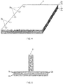
- FIG. 4 is a perspective view of the preform 2 according to an example embodiment.
- FIG. 5 is a side view of another preform 2 according to an example embodiment.
- FIG. 6 is a partially-ruptured perspective view of a fiber material 2a structuring the preform 2.
- FIG. 7 is a perspective cross-sectional view of the aliphatic polyamide fiber 24 included in the fiber material 2a.
- the preform 2 includes a stack of a plurality of fiber materials 2a.
- the fiber materials 2a that are adjacent to each other in the preform 2 may be joined to each other in all or a part of a region of the preform 2.
- the mutually-adjacent fiber materials 2a may be joined to each other in a region denoted by a reference numeral 2b in FIGs. 4 and 5 .
- the region denoted by the reference numeral 2b will be hereinafter referred to as a joint 2b.
- a plurality of dot-shaped joints 2b may be provided along a side of the fiber materials 2a.
- one dot-shaped joint 2b may be provided along a side of the fiber materials 2a, or the joint 2b may be provided linearly along a side of the fiber materials 2a.
- the joint 2b may be a planar joint 2b that extends not only along a side of the fiber materials 2a but also in a direction orthogonal to the side of the fiber materials 2a.
- the planar joint 2b may extend throughout the entire fiber materials 2a.
- the fiber materials 2a each include the second fiber 21 and a fourth fiber 22A.
- the preform 2 in an example embodiment may include the stack of the fiber materials 2a in which their respective orientations are matched with each other.
- the second fiber 21 and the fourth fiber 22A may be arranged alternately.
- the fiber materials 2a may be rectangular in a case of manufacturing the preform 2 illustrated in FIG. 4 or FIG. 5 .
- the fiber materials 2a each may have a strip shape in planar view as illustrated in FIG. 6 .
- the fiber materials 2a each may have a tow shape that is thinner than the strip-shaped fiber material 2a.
- the reinforcing fiber may be an inorganic fiber such as a carbon fiber or a glass fiber, or may be an organic fiber such as an aramid fiber or a Vectran (Registered Trademark) fiber.
- the reinforcing fiber may be a carbon fiber.
- the carbon fiber allows for the fiber-reinforced resin composite material 100 which is light in weight and high in durability.
- the reinforcing fibers may have a combination of two or more reinforcing fibers that are different in kind from each other.
- a method of forming the second fiber 21, such as a weaving method or a knitting method, a thickness of each of the reinforcing fibers, or any other factor of the second fiber 21 is optional.
- the fourth fiber 22A may be a non-woven fabric that includes the aliphatic polyamide fibers 24.
- the fourth fiber 22A may include a woven fabric having woven aliphatic polyamide fibers 24, or include a knitted fabric having knitted aliphatic polyamide fibers 24.
- One reason is that the fourth fiber 22A including the woven fabric or the knitted fabric allows an amount of materials used in the fiber materials 2a to be even and allows for control of such amount of materials.
- the fourth fiber 22A may have the basis weight that is in a range from 3 g/m 2 to 30 g/m 2 .
- One reason is that the fourth fiber 22A in this range improves toughness and impact resistance.
- a lower limit of the maximum opening area of the fourth fiber 22A is not particularly limited.
- the lower limit of the maximum opening area of the fourth fiber 22A may be equal to or greater than 0.2 mm 2 .
- the lower limit may be equal to or greater than 0.3 mm 2 .
- the lower limit of equal to or greater than 0.2 mm 2 improves an impregnation property in which the fourth fiber 22A and the second fiber 21 are impregnated with a resin composition, as described later in greater detail.
- An upper limit of the maximum opening area of the fourth fiber 22A is not particularly limited. In one example, the upper limit of the maximum opening area of the fourth fiber 22A may be equal to or less than 3 mm 2 . In another example, the upper limit may be equal to or less than 1.5 mm 2 . One reason is that the upper limit of equal to or less than 3 mm 2 reduces the area of a region to be damaged attributed to application of an impact to the thus-obtained fiber-reinforced resin composite material 100, and increases Compression After Impact (hereinafter abbreviated as "CAI") as well.
- CAI Compression After Impact
- An upper limit of the elongation rate in the longitudinal direction of the fourth fiber 22A may be equal to or less than 100%.
- the aliphatic polyamide fiber 24 structuring the fourth fiber 22A includes the first polyamide resin and the second polyamide resin having a melting point higher than a melting point of the first polyamide resin by 7 degrees centigrade to 50 degrees centigrade.
- the aliphatic polyamide fiber 24 in an example embodiment may include: a core 24a that includes the second polyamide resin; and an outer peripheral part 24b that includes the first polyamide resin and covers the core 24a.
- the first polyamide resin structuring the outer peripheral part 24b may be polyamide 12.
- the polyamide 12 may have a melting point of 176 degrees centigrade (hereinafter referred to as PA12).
- the outer peripheral part 24b of the aliphatic polyamide fiber 24 is once melted and cured again in the joint 2b, allowing the fiber materials 2a, or the second fiber 21 and the fourth fiber 22A, to be joined to each other while allowing a shape of the core 24a to be maintained as it is without causing melting of the core 24a.
- the fiber-reinforced resin composite material 100 may be manufactured using the prepreg 1 and the preform 2.
- the fiber-reinforced resin composite material 100 may be manufactured using any manufacturing method, such as a Resin Transfer Molding (RTM).
- RTM Resin Transfer Molding
- the prepregs 1 may be stacked while performing application of heat, application of pressure, or both, in order to increase adhesion of each of the prepregs 1.
- the prepreg 1 may be shaped to form the first member 110 having a desired manufacturing shape.
- the second resin composition 3 may be injected into the mold with pressure.
- the space inside the preform 2 may be filled with the second resin composition 3.
- the space in the second fiber 21 and the space in the fourth fiber 22A may be thereby filled with the second resin composition 3.
- the second fibers 21 that are adjacent to each other may be separated away from each other not only in regions other than the joints 2b but also at the joint 2b in the preform 2 according to an example embodiment. Accordingly, the space between the second fibers 21 (or the space in the fourth fibers 22A) may serve as a flow passage of the injected second resin composition 3, allowing the preform 2 to be easily impregnated with the second resin composition 3. This also eliminates processes of attaching and removing an existing net-like flow medium that facilitates spreading of the resin composition.
- This configuration makes it difficult to form interfaces between the surface layer 1b of the prepreg 1 and the second resin composition 3 and between the first resin composition 13 and the second resin composition 3, and thereby helps to further improve the integrity between them.
- the cores 24a in the preform 2 and the high-melting-point polyamide particles 14 at the surface layer 1b of the prepreg 1 remain without involving melting, thereby maintaining the separation between the first fibers 11 that are adjacent to each other, the separation between the first fiber 11 and the second fiber 21, and the separation between the second fibers 21 that are adjacent to each other.
- This allows the resin composition present between the mutually-adjacent first fibers 11, between the first fiber 11 and the second fiber 21, and between the mutually-adjacent second fibers 21 to remain without being squeezed out by the mutually-adjacent fibers.
- the first resin composition 13 is cured to form the first member 110
- the second resin composition 3 is cured to cause the second member 120 to be formed integrally on a surface of the first member 110.
- Curing the mixture of the first resin composition 13 and the melted first polyamide resin may result in the formation of the first matrix resin 12, and curing the mixture of the second resin composition 3 and the melted first polyamide resin may result in the formation of the second matrix resin 23, allowing the second member 120 to be formed integrally on the surface of the first member 110.
- the fiber-reinforced resin composite material 100 may be thus manufactured by the example processes described above.
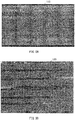
- FIGs. 8A and 8B are each a photograph of a cross-section of the first member 110 and the second member 120 structuring the fiber-reinforced resin composite material 100 and cut in a stack direction.
- the curing conditions included: increasing a temperature to 185 degrees centigrade at a heat-up rate of 1 degree centigrade per minute (1°C/min.); and curing by performing heating under pressure for two hours while keeping the increased temperature.
- the second fiber 21 structuring each of the fiber materials 2a was HiTape as with the Example 1.
- the fourth fiber 22A was the knitted fabric that had the aliphatic polyamide fibers 24 each having the core 24a and the outer peripheral part 24b including the PA12. Unlike the Example 1, the cores 24a each included PA6.
- the weight ratio of the cores 24a and the outer peripheral parts 24b was 50:50.
- the benzoxazine resin composition used for the filling and the curing conditions were similar to those of the Example 1.
- the samples according to the Comparative Example 3 were each manufactured using a stack that included only a plurality of prepregs 1.
- the prepregs 1 included the reinforcing fibers that were similar to those of the Comparative Example 2 but were each impregnated with the resin composition C. In other words, the samples were each manufactured using the stack that had no fourth fiber 22A between the reinforcing fibers.
- each sample was cut in a stack direction to observe a cross-section of each of the samples.
- samples according to the Examples 1 and 2, manufactured using the preform 2 each had a wavy cross-section as a whole in which a variation in layer thickness is apparent between respective areas as illustrated in FIG. 8B .
- the experiment included applying the impacts based on the same conditions to the respective six samples fabricated on the basis of the same conditions, and calculating, from thus-obtained respective measurement values, an average and a rate of variation (i.e., variations in CAI among the samples) of the measurement values.
- the CAIs of the samples according to the Examples 1 and 2 and the Comparative Example 2 were greater than 310 MPa, which result revealed that those samples, i.e., the fiber-reinforced resin composite materials, are able to withstand any practical use sufficiently.
- a member manufactured using the preform 2 in which the second fiber 21 and the fourth fiber 22A are stacked alternately has high impact resistance, which is about the same as that of a member manufactured using the prepreg 1 impregnated with the benzoxazine resin composition that includes the PA1010 and the PA12 particles or the PA6 and the PA12 particles.
- the fourth fiber 22A in at least one embodiment of the technology allows for manufacturing at low costs as compared with a case where the PA1010 particles, the PA12 particles, or the PA6 particles are used. Accordingly, the fiber-reinforced resin composite material 100 according to at least one embodiment of the technology that is free from using those particles for manufacturing the first member 110, the second member 120, or both, makes it possible to achieve, at lower costs, the impact resistance that is about the same as that of any existing fiber-reinforced resin composite material, manufactured using the polyamide particles for both of the first member 110 and the second member 120.
- the fourth fiber 22A including the aliphatic polyamide fibers 24 each having the core 24a that includes the PA1010 and the outer peripheral part 24b that includes the PA12 makes it possible to manufacture the fiber-reinforced resin composite material 100 having the high impact resistance more stably, i.e., with a reduced quality variation.
- a fiber-reinforced resin composite material having a complex shape including a first member and a second member formed integrally with the first member.
Landscapes
- Chemical & Material Sciences (AREA)
- Engineering & Computer Science (AREA)
- Materials Engineering (AREA)
- Mechanical Engineering (AREA)
- Health & Medical Sciences (AREA)
- Chemical Kinetics & Catalysis (AREA)
- Medicinal Chemistry (AREA)
- Polymers & Plastics (AREA)
- Organic Chemistry (AREA)
- Manufacturing & Machinery (AREA)
- Composite Materials (AREA)
- Physics & Mathematics (AREA)
- Textile Engineering (AREA)
- Mathematical Physics (AREA)
- Thermal Sciences (AREA)
- Reinforced Plastic Materials (AREA)
- Laminated Bodies (AREA)
Abstract
Description
- The technology relates to a fiber-reinforced resin composite material and a method of manufacturing the fiber-reinforced resin composite material.
- Japanese Patent No.
5904521 5904521 - Japanese Patent No.
5584047 5584047 - An aspect of the technology provides a fiber-reinforced resin composite material that includes a first member and a second member. The first member includes a first fiber and a first matrix resin. The first fiber includes a reinforcing fiber and has a sheet shape and is impregnated with the first matrix resin. The reinforcing fiber has a melting point and a tensile strength that are higher than a melting point and a tensile strength of an aliphatic polyamide fiber. The first matrix resin is cured. The second member includes a stack and a second matrix resin, and is provided on a surface of the first member. The stack includes a second fiber and a third fiber that are stacked alternately and that are filled with the second matrix resin. The second fiber includes the reinforcing fiber and has a sheet shape. The third fiber has a sheet shape. The second matrix resin is cured. The second matrix resin includes a component common to a component of the first matrix resin, and includes a first polyamide resin that includes an aliphatic polyamide resin. The third fiber includes a second polyamide resin. The second polyamide resin includes an aliphatic polyamide resin and has a melting point higher than a melting point of the first polyamide resin by 7 degrees centigrade to 50 degrees centigrade.
- An aspect of the technology provides a method of manufacturing a fiber-reinforced resin composite material. The method includes: preparing a prepreg that includes a first fiber impregnated with a first resin composition, in which the first fiber includes a reinforcing fiber and has a sheet shape, and the reinforcing fiber has a melting point and a tensile strength that are higher than a melting point and a tensile strength of an aliphatic polyamide fiber; preparing a preform that includes a stack of a plurality of fiber materials each including a second fiber and a fourth fiber, in which the second fiber includes the reinforcing fiber and has a sheet shape, the fourth fiber includes an aliphatic polyamide resin and is provided on at least one of surfaces of the first fiber, the fourth fiber includes a polyamide fiber, and the polyamide fiber includes a first polyamide resin and a second polyamide resin having a melting point higher than a melting point of the first polyamide resin by 7 degrees centigrade to 50 degrees centigrade; disposing the preform on a surface of the prepreg; filling a space inside the preform with a second resin composition, in which the second resin composition includes a component common to a component of the first resin composition; heating the preform and the second resin composition at a temperature that is higher than the melting point of the first polyamide resin and lower than the melting point of the second polyamide resin to melt the first polyamide resin of the fourth fiber; and curing, after the heating, the first resin composition and the second resin composition to form a first member and to integrally form a second member on a surface of the first member, in which a resultant mixture of the second resin composition and the melted first polyamide resin is cured together with the first resin composition after the heating.
- The accompanying drawings are included to provide a further understanding of the disclosure, and are incorporated in and constitute a part of this specification. The drawings illustrate embodiments and, together with the specification, serve to explain the principles of the technology.
-
FIG. 1 is a perspective view of a fiber-reinforced resin composite material according to one example embodiment of the technology. -
FIG. 2 is a schematic cross-sectional view of the fiber-reinforced resin composite material illustrated inFIG. 1 and taken along line II-II inFIG. 1 . -
FIGs. 3A and 3B are each a cross-sectional view of a prepreg used for manufacturing of the fiber-reinforced resin composite material illustrated inFIG. 1 . -
FIG. 4 is a perspective view of a preform used for manufacturing of the fiber-reinforced resin composite material illustrated inFIG. 1 . -
FIG. 5 is a side view of another preform used for manufacturing of the fiber-reinforced resin composite material illustrated inFIG. 1 . -
FIG. 6 is a partially-ruptured perspective view of a fiber material structuring the preform illustrated inFIG. 4 or FIG. 5 . -
FIG. 7 is an enlarged perspective cross-sectional view of an aliphatic polyamide fiber included in the fiber material illustrated inFIG. 6 . -
FIGs. 8A and 8B are each a photograph of a cross-section of the fiber-reinforced resin composite material illustrated inFIG. 1 . - For further popularization of a fiber-reinforced resin composite material, it is desirable that manufacturing costs be reduced. Polyamide particles included in a resin composition disclosed in Japanese Patent No.
5584047 - It is desirable to manufacture, at low costs while keeping a predetermined level of impact resistance or higher, a fiber-reinforced resin composite material having a complex shape including a first member and a second member formed integrally with the first member.
- In the following, some example embodiments of the technology are described in detail with reference to the accompanying drawings. Note that the following description is directed to illustrative examples of the disclosure and not to be construed as limiting to the technology. Factors including, without limitation, numerical values, shapes, materials, components, positions of the components, and how the components are coupled to each other are illustrative only and not to be construed as limiting to the technology. Further, elements in the following example embodiments which are not recited in a most-generic independent claim of the disclosure are optional and may be provided on an as-needed basis. The drawings are schematic and are not intended to be drawn to scale. Throughout the present specification and the drawings, elements having substantially the same function and configuration are denoted with the same reference numerals to avoid any redundant description.
- A description is given first of a fiber-reinforced resin
composite material 100 according to an example embodiment of the technology.FIG. 1 is a perspective view of the fiber-reinforced resincomposite material 100.FIG. 2 is a schematic cross-sectional view of the fiber-reinforced resincomposite material 100 taken along line II-II inFIG. 1 . - Note that underlined reference numerals in
FIG. 2 each indicate that a configuration denoted by an underlined reference numeral is included in a configuration denoted by a non-underlined reference numeral adjacent to the corresponding underlined reference numeral. - Referring to
FIG. 1 , the fiber-reinforcedresin composite material 100 according to an example embodiment includes afirst member 110 and asecond member 120. - The
first member 110 may have a plate shape. For example, thefirst member 110 may eventually serve as an outer panel of a vehicle or an aircraft. - In one example, the
first member 110 may have a flat-plate shape having a flat surface as illustrated inFIG. 1 (flat upper and lower surfaces inFIG. 1 ). In an alternative example, thefirst member 110 may have a curved surface or a gently-curved surface. In a yet alternative example, thefirst member 110 may be curved at a plurality of locations to have a corrugated-plate shape. - The
second member 120 may have a three-dimensional shape. For example, thesecond member 120 may serve as a reinforcing member of thefirst member 110. Thesecond member 120 may be provided on a surface of thefirst member 110 in which reinforcement is desirable. - In one example, the
second member 120 may have a T-shape, as viewed from a side, that includes acontact part 120a and arib 120b. Thecontact part 120a may be in contact with thefirst member 110. Therib 120b may be erected from the middle of thecontact part 120a. However, thesecond member 120 may have any shape as long as thesecond member 120 has a shape more complex than a shape of thefirst member 110. - Referring to
FIG. 2 , thefirst member 110 according to an example embodiment may include a plurality offirst layers 110a and a plurality ofsecond layers 110b. - In an example embodiment, the
first layer 110a and thesecond layer 110b may be stacked alternately. - In one example, the
first member 110 may include the plurality offirst layers 110a as illustrated inFIG. 2 . In an alternative example, thefirst member 110 may include at least onefirst layer 110a. - The
first layer 110a includes afirst fiber 11 and afirst matrix resin 12 that is cured. - The
second layer 110b may include a high-melting-point polyamide particle 14 and thefirst matrix resin 12 that is cured. - The
first fiber 11 structuring thefirst layer 110a has a sheet shape, and includes reinforcing fibers each having a melting point and a tensile strength that are higher than those of an aliphatic polyamide fiber. - The high-melting-
point polyamide particle 14 structuring thesecond layer 110b may be interposed between thefirst fibers 11 that are adjacent to each other. - In an example embodiment, the high-melting-
point polyamide particle 14 may be interposed between thefirst fiber 11, positioned closest to thesecond member 120, and thesecond member 120. - With this configuration, a space between the
first fibers 11 that are adjacent to each other and a space between thefirst fiber 11, positioned closest to thesecond member 120, and thesecond member 120 each may be separated away from each other at least by an amount corresponding to a diameter of the high-melting-point polyamide particle 14. - Thus, the
first fiber 11 may be impregnated with thefirst matrix resin 12 that structures thefirst layer 110a and thesecond layer 110b. In addition, the space between the mutually-adjacentfirst fibers 11 that are separated away from each other by the interposition of the high-melting-point polyamide particle 14 and the space between thefirst fiber 11, positioned closest to thesecond member 120, and thesecond member 120 that are also separated away from each other by the interposition of the high-melting-point polyamide particle 14 each may be filled with thefirst matrix resin 12. - In an example embodiment, the
first matrix resin 12 may include afirst resin composition 13 and a first polyamide resin. - The
first resin composition 13 and the first polyamide resin are described later in greater detail together with a later-described prepreg. - The
second member 120 includes a plurality ofthird layers 120c and a plurality offourth layers 120d. - In an example embodiment, the
third layer 120c and thefourth layer 120d may be stacked alternately. - In one example, one
third layer 120c and onefourth layer 120d may be stacked alternately as illustrated inFIG. 2 . In an alternative example, a laminate of thethird layers 120c and thefourth layer 120d may be stacked alternately. - The
third layer 120c includes asecond fiber 21 and asecond matrix resin 23 that is cured. - The
fourth layer 120d includes athird fiber 22 and thesecond matrix resin 23 that is cured. - The
second fiber 21 structuring thethird layer 120c has a sheet shape, and includes reinforcing fibers. - In one example, the reinforcing fibers each may have a melting point and a tensile strength that are higher than those of an aliphatic polyamide fiber. In another example, the reinforcing fibers each may have the melting point and the tensile strength that are same as or different from those of the aliphatic polyamide fiber structuring the
first fiber 11. - The
third fiber 22 structuring thefourth layer 120d includes a second polyamide resin. - In an example embodiment, the
third fiber 22 has a sheet shape. - As described previously, in an example embodiment, the
second fiber 21 and thethird fiber 22 may be stacked alternately, allowing thethird fiber 22 to be interposed between thesecond fibers 21 that are adjacent to each other. - With this configuration, the
second fibers 21 that are adjacent to each other may be separated away from each other at least by an amount corresponding to a thickness of thethird fiber 22. - Thus, the
second fiber 21 may be impregnated with thesecond matrix resin 23 that structures thethird layer 120c and thefourth layer 120d. In addition, a space between thesecond fiber 21 and thethird fiber 22 that are adjacent to each other may be filled with thesecond matrix resin 23. - In an example embodiment, the
second matrix resin 23 includes a second resin composition 3 and the first polyamide resin. - The second resin composition 3 may have a same composition as the
first resin composition 13. Accordingly, in an example embodiment, thesecond matrix resin 23 includes a component common to a component of thefirst matrix resin 12. - The
second matrix resin 23 may be integral with thefirst matrix resin 12 of thefirst member 110. - In some embodiments, the
second member 120 may include ayarn 16 that penetrates thesecond fiber 21 and thethird fiber 22 in a direction in which thesecond fiber 21 and thethird fiber 22 are stacked, as denoted by a broken line inFIG. 2 . - In one example, the
second fiber 21 of thesecond member 120 may be in contact with thefirst member 110 as illustrated inFIG. 2 . In an alternative example, the arrangement of thesecond fiber 21 and thethird fiber 22 in thesecond member 120 may be reversed to allow thethird fiber 22 to be in contact with thefirst member 110. - A description is given next of a
prepreg 1 used for manufacturing of thefirst member 110 of the fiber-reinforcedresin composite material 100.FIGs. 3A and 3B are each a cross-sectional view of theprepreg 1. - Note that underlined reference numerals in
FIGs. 3A and 3B each indicate that a configuration denoted by an underlined reference numeral is included in a configuration denoted by a non-underlined reference numeral adjacent to the corresponding underlined reference numeral. - Referring to
FIGs. 3A and 3B , in an example embodiment, theprepreg 1 may include anintermediate layer 1a and asurface layer 1b. - The
intermediate layer 1a may include thefirst fiber 11 and thefirst resin composition 13 with which fibers in thefirst fiber 11 are impregnated. - The
surface layer 1b may include thefirst resin composition 13. Thefirst resin composition 13 may have a component same as a component of thefirst resin composition 13 that structures theintermediate layer 1a. Thesurface layer 1b may be provided on both sides of theintermediate layer 1a. - The
first fiber 11 structuring theintermediate layer 1a may correspond to thefirst fiber 11 included in thefirst member 110. Thefirst fiber 11 includes a plurality of reinforcing fibers and has a sheet shape. - The reinforcing fibers each have a melting point and a tensile strength that are higher than those of an
aliphatic polyamide fiber 24. - The reinforcing fiber may be an inorganic fiber such as a carbon fiber or a glass fiber, or may be an organic fiber such as an aramid fiber or a Vectran (Registered Trademark) fiber. In some embodiments, the reinforcing fiber may be a carbon fiber. One reason is that the carbon fiber allows for the fiber-reinforced
resin composite material 100 which is light in weight and high in durability. - In one example, the reinforcing fibers may have a combination of two or more reinforcing fibers that are different in kind from each other.
- Note that a method of forming the
first fiber 11, such as a weaving method or a knitting method, a thickness of each of the reinforcing fibers, or any other factor of thefirst fiber 11 is optional. - The
first resin composition 13 structuring theintermediate layer 1a and thesurface layer 1b is not particularly limited, and any known resin composition may be used. In some embodiments, thefirst resin composition 13 may include a benzoxazine resin composition. In some embodiments, the benzoxazine resin composition may include: a benzoxazine resin including a compound having a benzoxazine ring expressed by the following formula (1) in a molecule; an epoxy resin; a curing agent having two or more phenolic hydroxyl groups in a molecule; and a toughness improver. One reason is that such afirst resin composition 13 is advantageous in terms of flame retardancy and low contractility. - Note that the
first resin composition 13 in theprepreg 1 may be semi-cured.
- In the formula (1), R1 denotes a chain alkyl group having 1 to 12 carbon atoms, a cyclic alkyl group having 3 to 8 carbon atoms, a phenyl group, a phenyl group substituted with the chain alkyl group having 1 to 12 carbon atoms, or a phenyl group substituted with a halogen. In addition, a hydrogen atom is bonded to at least one of a carbon atom in the ortho position or a carbon atom in the para position of a carbon atom, in an aromatic ring in the formula, to which an oxygen atom is bonded.
- In an example embodiment, the
surface layer 1b may have thefirst resin composition 13, the high-melting-point polyamide particle 14, and a low-melting-point polyamide particle 15. - The high-melting-
point polyamide particle 14 may correspond to the high-melting-point polyamide particle 14 of thefirst member 110. In some embodiments, the high-melting-point polyamide particle 14 may include the second polyamide resin. The second polyamide resin is an aliphatic polyamide resin. - In some embodiments, the second polyamide resin may be polyamide 1010 or polyamide 6. The polyamide 1010 may have a malting point of 202 degrees centigrade (hereinafter referred to as PA1010), and the polyamide 6 may have a melting point of 225 degrees centigrade (hereinafter referred to as PA6).
- In some embodiments, the low-melting-
point polyamide particle 15 may include the first polyamide resin. The first polyamide resin is an aliphatic polyamide resin. - In some embodiments, the first polyamide resin may be polyamide 12. The
polyamide 12 may have a melting point of 176 degrees centigrade (hereinafter referred to as PA12). - In some embodiments, the high-melting-
point polyamide particle 14 and the low-melting-point polyamide particle 15 may be mixed in thefirst resin composition 13 that structures thesurface layer 1b as illustrated inFIG. 3A . In some embodiments, the high-melting-point polyamide particle 14 and the low-melting-point polyamide particle 15 may be attached to a surface of thefirst resin composition 13 that structures thesurface layer 1b. The surface of thefirst resin composition 13 may be positioned on the opposite side of a surface, in contact with theintermediate layer 1a, of thefirst resin composition 13 as illustrated inFIG. 3B . - In some embodiments, the
surface layer 1b may not have the high-melting-point polyamide particle 14 and the low-melting-point polyamide particle 15. In such an embodiment, thesecond layer 110b may be free from the high-melting-point polyamide particle 14, and thefirst matrix resin 12 may be free from the first polyamide resin. - A description is given next of a
preform 2 used for manufacturing of thesecond member 120 of the fiber-reinforcedresin composite material 100.FIG. 4 is a perspective view of thepreform 2 according to an example embodiment.FIG. 5 is a side view of anotherpreform 2 according to an example embodiment.FIG. 6 is a partially-ruptured perspective view of afiber material 2a structuring thepreform 2.FIG. 7 is a perspective cross-sectional view of thealiphatic polyamide fiber 24 included in thefiber material 2a. - Referring to
FIG. 4 or FIG. 5 , thepreform 2 according to an example embodiment includes a stack of a plurality offiber materials 2a. - Note that a shape of the
preform 2 may be determined depending on any intended use and is not particularly limited accordingly. For example, thepreform 2 may have a flat-plate shape as illustrated inFIG. 4 . In one example, thepreform 2 may be shaped to have a predetermined three-dimensional shape or may be bent. In another example, thepreform 2 may have a combination of the flat-plate shape and the three-dimensional shape as illustrated inFIG. 5 . - The
preform 2 may include the stack of thefiber materials 2a that are rectangular in plan view as illustrated inFIG. 4 . In an alternative example, thepreform 2 may include the stack of strip-shapedfiber materials 2a. - The
preform 2 may be shaped to have an L-shape as viewed from a side. In an alternative example, thepreform 2 may have any other shape as viewed from a side, such as a C-shape, a U-shape, or a hat (Ω) shape. - Upon manufacturing the shaped
preform 2, the plurality offiber materials 2a may be stacked in a state in which the plurality offiber materials 2a is placed flat, following which the plurality offiber materials 2a may be subjected to bending. In an alternative example, the plurality offiber materials 2a bent in advance may be stacked, upon manufacturing the shapedpreform 2. - The
fiber materials 2a that are adjacent to each other in thepreform 2 may be joined to each other in all or a part of a region of thepreform 2. For example, the mutually-adjacent fiber materials 2a may be joined to each other in a region denoted by areference numeral 2b inFIGs. 4 and 5 . The region denoted by thereference numeral 2b will be hereinafter referred to as a joint 2b. - In an example embodiment, one end of each of the
fiber materials 2a may be fusion bonded, allowing the other end of each of thefiber materials 2a to move or shift with respect to the other end of theadjacent fiber material 2a. This configuration allows for easier bending upon further processing thepreform 2 having the flat-plate shape, and also prevents formation of a gap between theinner fiber material 2a and theouter fiber material 2a adjacent to theinner fiber material 2a upon further bending of thepreform 2. - Note that a method of joining the
fiber materials 2a is not limited to the fusion bonding. For example, a yarn may be threaded through the plurality offiber materials 2a in a stack direction. In an alternative example, a resin other than a resin structuring thepreform 2 may be used to adhere thefiber materials 2a. - In some embodiments, a three-dimensional woven fabric may be used as the
preform 2, instead of providing the joint 2b. For example, the three-dimensional woven fabric may be available from Toyota Industries Corporation located in Aichi, Japan. As illustrated inFIG. 2 , the three-dimensional woven fabric may include thesecond fiber 21, thethird fiber 22, and theyarn 16 that penetrates through or stitches thesecond fiber 21 and thethird fiber 22 in a stack direction thereof. Theyarn 16 used for the three-dimensional woven fabric may include an organic material or an inorganic material. The use of the three-dimensional woven fabric having theyarn 16 makes it difficult to cause delamination of thefiber materials 2a in the fiber-reinforcedresin composite material 100, thereby improving impact resistance of the fiber-reinforcedresin composite material 100. - As illustrated in
FIG. 4 , a plurality of dot-shapedjoints 2b may be provided along a side of thefiber materials 2a. In an alternative example, one dot-shaped joint 2b may be provided along a side of thefiber materials 2a, or the joint 2b may be provided linearly along a side of thefiber materials 2a. In a yet alternative example, the joint 2b may be a planar joint 2b that extends not only along a side of thefiber materials 2a but also in a direction orthogonal to the side of thefiber materials 2a. For example, the planar joint 2b may extend throughout theentire fiber materials 2a. - As illustrated in
FIG. 4 , thejoints 2b may be provided only at one end of thefiber materials 2a. In an alternative example, optionally, thejoints 2b may be provided not only at one end of thefiber materials 2a but also at the other end of thefiber materials 2a to maintain its shape. - Referring to
FIG. 6 , thefiber materials 2a each include thesecond fiber 21 and afourth fiber 22A. - In the
fiber materials 2a of an example embodiment, thefourth fiber 22A may be provided on only one surface of thesecond fiber 21. - The
preform 2 in an example embodiment may include the stack of thefiber materials 2a in which their respective orientations are matched with each other. Thus, thesecond fiber 21 and thefourth fiber 22A may be arranged alternately. - Note that providing the
fourth fiber 22A on at least one of surfaces of thesecond fiber 21 suffices. In one example, thefourth fiber 22A may be provided on both surfaces of thesecond fiber 21. - It is to be also noted that stacking one
second fiber 21 and onefourth fiber 22A alternately is not essential. In one example, a bundle of thesecond fibers 21 and thefourth fiber 22A may be stacked alternately. - A planar shape of each of the
fiber materials 2a in an example embodiment may be determined depending on any shape of thepreform 2 to be manufactured and is not particularly limited accordingly. - For example, the
fiber materials 2a may be rectangular in a case of manufacturing thepreform 2 illustrated inFIG. 4 or FIG. 5 . - In one example, the
fiber materials 2a each may have a strip shape in planar view as illustrated inFIG. 6 . In an alternative example, thefiber materials 2a each may have a tow shape that is thinner than the strip-shapedfiber material 2a. - The
second fiber 21 in an example embodiment may correspond to thesecond fiber 21 included in thesecond member 120. Thesecond fiber 21 includes a plurality of reinforcing fibers and has a sheet shape. - The reinforcing fibers each may have a melting point and a tensile strength that are higher than those of the
aliphatic polyamide fiber 24. - The reinforcing fiber may be an inorganic fiber such as a carbon fiber or a glass fiber, or may be an organic fiber such as an aramid fiber or a Vectran (Registered Trademark) fiber. In some embodiments, the reinforcing fiber may be a carbon fiber. One reason is that the carbon fiber allows for the fiber-reinforced
resin composite material 100 which is light in weight and high in durability. - In one example, the reinforcing fibers may have a combination of two or more reinforcing fibers that are different in kind from each other.
- Note that a method of forming the
second fiber 21, such as a weaving method or a knitting method, a thickness of each of the reinforcing fibers, or any other factor of thesecond fiber 21 is optional. - The
fourth fiber 22A in an example embodiment may eventually serve as thethird fiber 22 of thesecond member 120. Thefourth fiber 22A includes the plurality ofaliphatic polyamide fibers 24 and may have a sheet shape. For example, thealiphatic polyamide fiber 24 may be a nylon fiber. - In one example, the
fourth fiber 22A may be a non-woven fabric that includes thealiphatic polyamide fibers 24. In some embodiments, thefourth fiber 22A may include a woven fabric having wovenaliphatic polyamide fibers 24, or include a knitted fabric having knittedaliphatic polyamide fibers 24. One reason is that thefourth fiber 22A including the woven fabric or the knitted fabric allows an amount of materials used in thefiber materials 2a to be even and allows for control of such amount of materials. - In one example, the
fourth fiber 22A may have the basis weight that is in a range from 3 g/m2 to 30 g/m2. One reason is that thefourth fiber 22A in this range improves toughness and impact resistance. - A lower limit of the maximum opening area of the
fourth fiber 22A is not particularly limited. In one example, the lower limit of the maximum opening area of thefourth fiber 22A may be equal to or greater than 0.2 mm2. In another example, the lower limit may be equal to or greater than 0.3 mm2. One reason is that the lower limit of equal to or greater than 0.2 mm2 improves an impregnation property in which thefourth fiber 22A and thesecond fiber 21 are impregnated with a resin composition, as described later in greater detail. - An upper limit of the maximum opening area of the
fourth fiber 22A is not particularly limited. In one example, the upper limit of the maximum opening area of thefourth fiber 22A may be equal to or less than 3 mm2. In another example, the upper limit may be equal to or less than 1.5 mm2. One reason is that the upper limit of equal to or less than 3 mm2 reduces the area of a region to be damaged attributed to application of an impact to the thus-obtained fiber-reinforcedresin composite material 100, and increases Compression After Impact (hereinafter abbreviated as "CAI") as well. - A lower limit of an elongation rate in a longitudinal direction (or in a vertical direction) of the
fourth fiber 22A is not particularly limited. In one example, the lower limit of the elongation rate of thefourth fiber 22A may be equal to or greater than 5%. In another example, the lower limit may be equal to or greater than 10%. One reason is that the lower limit of equal to or greater than 5% makes it difficult to cause a wrinkle in thefiber materials 2a upon manufacturing thepreform 2, and thereby achieves thepreform 2 having reduced unnecessary irregularities. - An upper limit of the elongation rate in the longitudinal direction of the
fourth fiber 22A may be equal to or less than 100%. - The
aliphatic polyamide fiber 24 structuring thefourth fiber 22A includes the first polyamide resin and the second polyamide resin having a melting point higher than a melting point of the first polyamide resin by 7 degrees centigrade to 50 degrees centigrade. - Referring to
FIG. 7 , thealiphatic polyamide fiber 24 in an example embodiment may include: acore 24a that includes the second polyamide resin; and an outerperipheral part 24b that includes the first polyamide resin and covers thecore 24a. - In one example, the second polyamide resin structuring the
core 24a may be polyamide 1010 or polyamide 6. The polyamide 1010 may have a malting point of 202 degrees centigrade (hereinafter referred to as PA1010), and the polyamide 6 may have a melting point of 225 degrees centigrade (hereinafter referred to as PA6). - In one example, the first polyamide resin structuring the outer
peripheral part 24b may be polyamide 12. Thepolyamide 12 may have a melting point of 176 degrees centigrade (hereinafter referred to as PA12). - In one example, a ratio of the mass of the first polyamide resin (i.e., the outer
peripheral part 24b) included in thealiphatic polyamide fiber 24 and the mass of the second polyamide resin (i.e., the core 24a) included in thealiphatic polyamide fiber 24 may be in a range from 30:70 to 70:30. In another example, the ratio may be 50:50. One reason is that the ratio of 50:50 improves a fusion bonding property and helps to ensure a sufficient space as described later in greater detail. - In one example, the
second fiber 21 and thefourth fiber 22A of each of thefiber materials 2a may be joined to each other in all or a part of a region of corresponding one of thefiber materials 2a. - For example, a region of the joint 2b in which the
fiber materials 2a are joined to each other and a region, in each of thefiber materials 2a, in which thesecond fiber 21 and thefourth fiber 22A are joined to each other may be the same as each other or may be different from each other. - In an example embodiment, the
second fiber 21 and thefourth fiber 22A may be joined to each other through fusion bonding as with the joining of thefiber materials 2a. In an alternative example, a method of joining thefiber materials 2a and a method of joining thesecond fiber 21 and thefourth fiber 22A in each of thefiber materials 2a may be different from each other. - In an example embodiment, the fusion bonding of the
fiber materials 2a and the fusion bonding of thesecond fiber 21 and thefourth fiber 22A are performed at a temperature that is higher than the melting point of the first polyamide resin (i.e., the outerperipheral part 24b) and lower than the melting point of the second polyamide resin (i.e., the core 24a). - With this configuration, the outer
peripheral part 24b of thealiphatic polyamide fiber 24 is once melted and cured again in the joint 2b, allowing thefiber materials 2a, or thesecond fiber 21 and thefourth fiber 22A, to be joined to each other while allowing a shape of the core 24a to be maintained as it is without causing melting of thecore 24a. - The
preform 2 in an example embodiment includes the stack of thefiber materials 2a in which thesecond fiber 21 and thefourth fiber 22A are arranged alternately. Thus, thecore 24a may be interposed between thesecond fibers 21 that are adjacent to each other in the joint 2b, allowing the mutually-adjacentsecond fibers 21 to be separated away from each other at least by an amount corresponding to the thickness of thecore 24a. - Note that, in a region excluding the joint 2b in the
preform 2, thealiphatic polyamide fiber 24 may be interposed as it is (i.e., without involving the melting of the outerperipheral part 24b) between thesecond fibers 21 that are adjacent to each other, allowing the mutually-adjacentsecond fibers 21 to be separated away from each other at least by an amount corresponding to a thickness of thefourth fiber 22A. - A description is given next of a method of manufacturing the fiber-reinforced
resin composite material 100 according to an example embodiment. - The fiber-reinforced
resin composite material 100 may be manufactured using theprepreg 1 and thepreform 2. The fiber-reinforcedresin composite material 100 may be manufactured using any manufacturing method, such as a Resin Transfer Molding (RTM). - First, at least one
prepreg 1 is prepared. - In some embodiments, upon preparing the
prepreg 1, the high-melting-point polyamide particle 14 and the low-melting-point polyamide particle 15 may be so disposed as to be in contact with thefirst resin composition 13. In one example, the high-melting-point polyamide particle 14 and the low-melting-point polyamide particle 15 may be mixed in thefirst resin composition 13, before thefirst fiber 11 is impregnated with thefirst resin composition 13. In an alternative example, the high-melting-point polyamide particle 14 and the low-melting-point polyamide particle 15 may be attached to a surface of thefirst resin composition 13 that configures thesurface layer 1b, after thefirst fiber 11 is impregnated with thefirst resin composition 13. - In addition, in an example embodiment, the stack of the plurality of
prepregs 1 is prepared. - In one example, the
prepregs 1 may be stacked while performing application of heat, application of pressure, or both, in order to increase adhesion of each of theprepregs 1. - Upon preparing the
prepreg 1, theprepreg 1 may be shaped to form thefirst member 110 having a desired manufacturing shape. - The
preform 2 having the shape of thesecond member 120 is prepared. Thepreform 2 may be prepared together with the preparation of theprepreg 1, or may be prepared before or after the preparation of theprepreg 1. - After preparing the
first member 110 and thepreform 2, thepreform 2 is disposed on a surface of theprepreg 1. Thepreform 2 may be disposed on a surface of theprepreg 1 in which reinforcement is desirable. - In an example embodiment, the
prepreg 1 and thepreform 2 may be placed in a mold. - Note that either one of the
second fiber 21 and thefourth fiber 22A comes into contact with theprepreg 1 depending on a way in which thepreform 2 is to be formed. In any case, theprepreg 1 has thesurface layer 1b, allowing the first fiber 11 (theintermediate layer 1a) of theprepreg 1 and the second and thefourth fibers preform 2 that are closest to theprepreg 1 to be separated away from each other at least by an amount corresponding to a thickness of thesurface layer 1b. - After disposing the
preform 2, a space inside thepreform 2 is filled with the second resin composition 3. - In an example embodiment, the second resin composition 3 may be injected into the mold with pressure. Thus, the space inside the
preform 2 may be filled with the second resin composition 3. For example, the space in thesecond fiber 21 and the space in thefourth fiber 22A may be thereby filled with the second resin composition 3. - As described previously, the
second fibers 21 that are adjacent to each other may be separated away from each other not only in regions other than thejoints 2b but also at the joint 2b in thepreform 2 according to an example embodiment. Accordingly, the space between the second fibers 21 (or the space in thefourth fibers 22A) may serve as a flow passage of the injected second resin composition 3, allowing thepreform 2 to be easily impregnated with the second resin composition 3. This also eliminates processes of attaching and removing an existing net-like flow medium that facilitates spreading of the resin composition. - The mold may be subjected to vacuuming upon filling the
preform 2 with the second resin composition 3. - In an example embodiment, the
preform 2 is filled with the second resin composition 3 that includes a component common to a component of thefirst resin composition 13. - This configuration makes it difficult to form interfaces between the
surface layer 1b of theprepreg 1 and the second resin composition 3 and between thefirst resin composition 13 and the second resin composition 3, and thereby helps to further improve the integrity between them. - After impregnating the
preform 2 with the second resin composition 3, theprepreg 1, thepreform 2, and the second resin composition 3 are heated at the temperature (i.e., a heating temperature) that is higher than the melting point of the first polyamide resin and lower than the melting point of the second polyamide resin to melt the first polyamide resin that forms the outerperipheral parts 24b of thealiphatic polyamide fibers 24. - In an example embodiment, a temperature may be increased from a room temperature to the heating temperature at a predetermined heat-up rate, following which heating is performed under pressure at the heating temperature for a predetermined time to melt the first polyamide resin.
- The
prepreg 1 in an example embodiment may have thesurface layer 1b that includes the first polyamide resin and the second polyamide resin. Thus, upon the heating, the low-melting-point polyamide particle 15 including the first polyamide resin may melt together with the first polyamide resin that forms the outerperipheral part 24b of thefourth fiber 22A. Thefourth fiber 22A following the melting of the outerperipheral part 24b may serve as thethird fiber 22. - In addition, upon the heating, the
cores 24a in thepreform 2 and the high-melting-point polyamide particles 14 at thesurface layer 1b of theprepreg 1 remain without involving melting, thereby maintaining the separation between thefirst fibers 11 that are adjacent to each other, the separation between thefirst fiber 11 and thesecond fiber 21, and the separation between thesecond fibers 21 that are adjacent to each other. This in turn allows the resin composition present between the mutually-adjacentfirst fibers 11, between thefirst fiber 11 and thesecond fiber 21, and between the mutually-adjacentsecond fibers 21 to remain without being squeezed out by the mutually-adjacent fibers. - Further, the thus-melted first polyamide resin mixes with the
first resin composition 13 or the second resin composition 3 to structure thefirst matrix resin 12 or thesecond matrix resin 23. - Thereafter, the
first resin composition 13 is cured to form thefirst member 110, and the second resin composition 3 is cured to cause thesecond member 120 to be formed integrally on a surface of thefirst member 110. - In an example embodiment, the resultant mixture of the
first resin composition 13 and the melted first polyamide resin is cured together with the resultant mixture of the second resin composition 3 and the melted first polyamide resin. - In one example where the
first resin composition 13 and the second resin composition 3 each include a thermoplastic resin, curing may be performed by cooling. In an alternative example where thefirst resin composition 13 and the second resin composition 3 each include a thermosetting resin, such as the benzoxazine resin composition, the application of pressure and the heating may be continued to perform the curing. - Curing the mixture of the
first resin composition 13 and the melted first polyamide resin may result in the formation of thefirst matrix resin 12, and curing the mixture of the second resin composition 3 and the melted first polyamide resin may result in the formation of thesecond matrix resin 23, allowing thesecond member 120 to be formed integrally on the surface of thefirst member 110. The fiber-reinforcedresin composite material 100 may be thus manufactured by the example processes described above. - The fiber-reinforced
resin composite material 100 according to an example embodiment described above includes thefourth fiber 22A (or thecore 24a at the joint 2b) interposed between thesecond fibers 21 that are adjacent to each other, allowing the mutually-adjacentsecond fibers 21 to be separated away from each other. Thus, the space between the second fibers 21 (or the space in thefourth fiber 22A) may serve as the flow passage of the injected second resin composition 3, allowing thepreform 2 to be easily impregnated with the second resin composition 3 and thereby makes it difficult to cause a void (a region unfilled with the resin) inside the thus-manufactured fiber-reinforcedresin composite material 100. Hence, it is possible to stably manufacture the fiber-reinforcedresin composite material 100 having high impact resistance. - A description is given next of some specific but non-limiting Examples of characteristics of the fiber-reinforced
resin composite material 100.FIGs. 8A and 8B are each a photograph of a cross-section of thefirst member 110 and thesecond member 120 structuring the fiber-reinforcedresin composite material 100 and cut in a stack direction. - The benzoxazine resin composition was manufactured first that eventually serves as a part of the
second matrix resin 23. The benzoxazine resin composition was obtained through heating and mixing of the following raw materials at a proportion represented in the Table 1 described below. -
- F-a: bisphenol F-aniline type solid benzoxazine (F-a type solid benzoxazine), available from Shikoku Chemicals Corporation located in Kagawa, Japan
- P-a: phenol aniline type solid benzoxazine (P-a type solid benzoxazine), available from Shikoku Chemicals Corporation located in Kagawa, Japan
-
- 2021P: liquid epoxy "CELLOXIDE" (Registered Trademark) 2021P, available from Daicel Corporation located in Osaka, Japan
-
- BPF: 9,9-bis(4-hydroxyphenyl) fluorene, available from Osaka Gas Chemicals Co., Ltd. located in Osaka, Japan
-
- YP70: phenoxy resin (YP-70), available from NIPPON STEEL Chemical & Material Co., Ltd. located in Tokyo, Japan
- In addition, a part of the benzoxazine resin composition was mixed with the following high-melting-
point polyamide particle 14 and low-melting-point polyamide particle 15 (E1 and E2 components or E1 and E3 components) to obtain other benzoxazine resin compositions as well. - In the following, the benzoxazine resin composition containing no high-melting-
point polyamide particle 14 and no low-melting-point polyamide particle 15 is referred to as a resin composition A, the benzoxazine resin composition containing the E1 component and the E2 component is referred to as a resin composition B, and the benzoxazine resin composition containing the E1 component and the E3 component is referred to as a resin composition C. -
- (E1) component:
polyamide 12 resin particles (the low-melting-point polyamide particles 15; hereinafter referred to as "PA12" particles)- VESTOSINT (Registered Trademark) 2158 having a mean particle size of 20 micrometers, available from Daicel-Evonik Ltd. located in Tokyo, Japan
- VESTOSINT (Registered Trademark) 2159 having a mean particle size of 10 micrometers, available from Daicel-Evonik Ltd. located in Tokyo, Japan
- (E2) component: polyamide 1010 resin particles (the high-melting-
point polyamide particles 14; hereinafter referred to as "PA1010" particles)- VESTOSINT (Registered Trademark) 9158 having a mean particle size of 20 micrometers, available from Daicel-Evonik Ltd. located in Tokyo, Japan
- (E3) component: polyamide 6 resin particles (the high-melting-
point polyamide particles 14; hereinafter referred to as "PA6" particles) - Flat-plate-shaped
second members 120 according to Examples 1 and 2 and flat-plate-shapedfirst members 110 according to Comparative Examples 1 to 3 (hereinafter referred to as "samples") were fabricated on the basis of the specifications represented in Table 2 below. - Note that six fiber-reinforced resin composite materials were fabricated for each sample.
- The samples according to the Example 1 were each manufactured using the
preform 2 of an example embodiment described above, which included the stack of the plurality offiber materials 2a. - The
second fiber 21 structuring each of thefiber materials 2a was HiTape (Registered Trademark), available from Hexcel Corporation located in Anderson, S.C. The HiTape had the basis weight of the reinforcing fibers of 210 g/m2. Thefourth fiber 22A was the knitted fabric that had thealiphatic polyamide fibers 24 each having the core 24a including the PA1010 and the outerperipheral part 24b including the PA12. The weight ratio of thecores 24a and the outerperipheral parts 24b was 50:50. - The space in the
preform 2 was filled with the resin composition A as the benzoxazine resin composition. - The curing conditions included: increasing a temperature to 185 degrees centigrade at a heat-up rate of 1 degree centigrade per minute (1°C/min.); and curing by performing heating under pressure for two hours while keeping the increased temperature.
- The samples according to the Example 2 were each manufactured using the
preform 2 of an example embodiment described above, which included the stack of the plurality offiber materials 2a, as with the samples according to the Example 1. - The
second fiber 21 structuring each of thefiber materials 2a was HiTape as with the Example 1. Thefourth fiber 22A was the knitted fabric that had thealiphatic polyamide fibers 24 each having thecore 24a and the outerperipheral part 24b including the PA12. Unlike the Example 1, thecores 24a each included PA6. The weight ratio of thecores 24a and the outerperipheral parts 24b was 50:50. - The benzoxazine resin composition used for the filling and the curing conditions were similar to those of the Example 1.
- The samples according to the Comparative Example 1 were each manufactured using the
preform 2 that included a stack of only a plurality ofsecond fibers 21. Thesecond fibers 21 each included the HiTape as with the Examples 1 and 2. In other words, the samples were each manufactured using thepreform 2 that had nofourth fiber 22A between the HiTapes. - The benzoxazine resin composition used for the filling and the curing conditions were similar to those of the Examples 1 and 2.
- The samples according to the Comparative Example 2 were each manufactured using a stack that included only a plurality of
prepregs 1. Theprepregs 1 included sheet-shaped reinforcing fibers that were each impregnated with the resin composition B. In other words, the samples were each manufactured using the stack that had nofourth fiber 22A between the reinforcing fibers. - The curing conditions were similar to those of the Examples 1 and 2 and the Comparative Example 1.
- The samples according to the Comparative Example 3 were each manufactured using a stack that included only a plurality of
prepregs 1. Theprepregs 1 included the reinforcing fibers that were similar to those of the Comparative Example 2 but were each impregnated with the resin composition C. In other words, the samples were each manufactured using the stack that had nofourth fiber 22A between the reinforcing fibers. - The curing conditions were similar to those of the Examples 1 and 2 and the Comparative Examples 1 and 2.
[Table 2] Sample Fiber Material Polyamide (PA) CAI Basis Weight of Reinforcing Fibers [g/m2] Resin Content [wt%] Fibers General Resin Component Particles Basis Weight [g/m2] Knitted Fabric Basis Weight [g/m2] Average [MPa] Rate of Variation [%] Example 1 RTM material (HiTape) 210 35.5 IM7 Benzoxazine resin - - 1010/12 5.5 334 4.1 Example 2 RTM material (HiTape) 210 35.5 IM7 Benzoxazine resin - - 6/12 - 311 - Comparative Example 1 RTM material (HiTape) 210 35.5 IM7 Benzoxazine resin - - - - 177 5.8 Comparative Example 2 Prepreg 150 35.5 IMS65 Benzoxazine resin 1010/12 - - - 314 5.5 Comparative Example 3 Prepreg 150 35.5 IMS65 Benzoxazine resin 6/12 - - - 291 2.6 - First, each sample was cut in a stack direction to observe a cross-section of each of the samples.
- The samples according to the Comparative Examples 2 and 3, manufactured through stacking the plurality of
prepregs 1, each had an even cross-section as a whole in which a variation in layer thickness is small between respective areas as illustrated inFIG. 8A . - In contrast, the samples according to the Examples 1 and 2, manufactured using the
preform 2, each had a wavy cross-section as a whole in which a variation in layer thickness is apparent between respective areas as illustrated inFIG. 8B . - Thereafter, an impact was applied to the middle of each of the samples to measure the CAI of each of the samples. The experiment was conducted in compliance with ASTM D7136 and ASTM D7137 and conducted under Room Temperature, Dry (RTD). The impact applied to each of the samples had energy of 6.7 J/m2.
- The experiment included applying the impacts based on the same conditions to the respective six samples fabricated on the basis of the same conditions, and calculating, from thus-obtained respective measurement values, an average and a rate of variation (i.e., variations in CAI among the samples) of the measurement values.
- A comparison result on an average of the CAIs of the respective samples revealed that an average of the CAIs of the samples according to the Comparative Example 1 was below 200 MPa as represented in the Table 2.
- In contrast, the CAIs of the samples according to the Examples 1 and 2 and the Comparative Examples 2 and 3 greatly exceeded the CAIs of the samples according to the Comparative Example 1. It is to be noted that averages of the CAIs of the samples according to the Examples 1 and 2 and the Comparative Examples 2 and 3 each exceeded 290 MPa.
- In particular, the CAIs of the samples according to the Examples 1 and 2 and the Comparative Example 2 were greater than 310 MPa, which result revealed that those samples, i.e., the fiber-reinforced resin composite materials, are able to withstand any practical use sufficiently.
- In addition, a comparison result on the rate of variation of the CAIs of the respective samples revealed that the rate of variation of the measurement values, i.e., the variations among the CAIs, of each of the samples according to the Comparative Examples 1 and 2 was 5.5% or greater and was relatively high accordingly, as represented in the Table 2. In contrast, the rate of variation of the measurement values of each of the samples according to the Example 1 and the Comparative Example 3 was 4.1% or less and was low accordingly.
- In view of the foregoing results, it was found that a member manufactured using the
preform 2 in which thesecond fiber 21 and thefourth fiber 22A are stacked alternately has high impact resistance, which is about the same as that of a member manufactured using theprepreg 1 impregnated with the benzoxazine resin composition that includes the PA1010 and the PA12 particles or the PA6 and the PA12 particles. - The
fourth fiber 22A in at least one embodiment of the technology allows for manufacturing at low costs as compared with a case where the PA1010 particles, the PA12 particles, or the PA6 particles are used. Accordingly, the fiber-reinforcedresin composite material 100 according to at least one embodiment of the technology that is free from using those particles for manufacturing thefirst member 110, thesecond member 120, or both, makes it possible to achieve, at lower costs, the impact resistance that is about the same as that of any existing fiber-reinforced resin composite material, manufactured using the polyamide particles for both of thefirst member 110 and thesecond member 120. - In particular, it was found that the
fourth fiber 22A including thealiphatic polyamide fibers 24 each having thecore 24a that includes the PA1010 and the outerperipheral part 24b that includes the PA12 makes it possible to manufacture the fiber-reinforcedresin composite material 100 having the high impact resistance more stably, i.e., with a reduced quality variation. - According to at least one embodiment of the technology, it is possible to manufacture, at low costs while keeping a predetermined level of impact resistance or higher, a fiber-reinforced resin composite material having a complex shape including a first member and a second member formed integrally with the first member.
- Although some example embodiments of the technology have been described in the foregoing by way of example with reference to the accompanying drawings, the technology is by no means limited to the embodiments described above. It should be appreciated that modifications and alterations may be made by persons skilled in the art without departing from the scope as defined by the appended claims. The technology is intended to include such modifications and alterations in so far as they fall within the scope of the appended claims or the equivalents thereof.
| Name of Raw Material | Manufacturer | Combination Rate |
| Solid benzoxazine (F-a) | Shikoku Chemicals Corporation | 60 |
| Solid benzoxazine (P-a) | |
15 |
| Liquid epoxy (Celloxide 2021P) | Daicel Corporation | 25 |
| Curing agent BPF (bis(4-hydroxyphenyl) fluorene) | Osaka Gas Chemicals Co., Ltd. | 10 |
| Phenoxy resin (YP-70) | NIPPON STEEL Chemical & Material Co., Ltd. | 5 |
Claims (11)
- A fiber-reinforced resin composite material comprising:a first member including a first fiber and a first matrix resin, the first fiber including a reinforcing fiber and having a sheet shape and being impregnated with the first matrix resin, the reinforcing fiber having a melting point and a tensile strength that are higher than a melting point and a tensile strength of an aliphatic polyamide fiber, the first matrix resin being cured; anda second member including a stack and a second matrix resin, and provided on a surface of the first member, the stack including a second fiber and a third fiber that are stacked alternately and that are filled with the second matrix resin, the second fiber including the reinforcing fiber and having a sheet shape, the third fiber having a sheet shape, the second matrix resin being cured, whereinthe second matrix resin includes a component common to a component of the first matrix resin, and includes a first polyamide resin that comprises an aliphatic polyamide resin, andthe third fiber includes a second polyamide resin, the second polyamide resin comprising an aliphatic polyamide resin and having a melting point higher than a melting point of the first polyamide resin by 7 degrees centigrade to 50 degrees centigrade.
- The fiber-reinforced resin composite material according to claim 1, wherein the component common between the first matrix resin and the second matrix resin comprises a benzoxazine resin composition.
- The fiber-reinforced resin composite material according to claim 2, wherein the benzoxazine resin composition includes:an epoxy resin;a curing agent;a toughness improver; anda compound having a benzoxazine ring expressed by the following formula (1) in a molecule,
 R1 denotes a chain alkyl group having 1 to 12 carbon atoms, a cyclic alkyl group having 3 to 8 carbon atoms, a phenyl group, a phenyl group substituted with the chain alkyl group having 1 to 12 carbon atoms, or a phenyl group substituted with a halogen, anda hydrogen atom is bonded to at least one of a carbon atom in an ortho position or a carbon atom in a para position of a carbon atom, in an aromatic ring in the formula (1), to which an oxygen atom is bonded.
 - The fiber-reinforced resin composite material according to any one of claims 1 to 3, wherein the first matrix resin includes a particle that includes the second polyamide resin.
- The fiber-reinforced resin composite material according to any one of claims 1 to 4, wherein the second member includes a yarn that penetrates the second fiber and the third fiber in a direction in which the second fiber and the third fiber are stacked.
- A method of manufacturing a fiber-reinforced resin composite material, the method comprising:preparing a prepreg that includes a first fiber impregnated with a first resin composition, the first fiber including a reinforcing fiber and having a sheet shape, the reinforcing fiber having a melting point and a tensile strength that are higher than a melting point and a tensile strength of an aliphatic polyamide fiber;preparing a preform that includes a stack of a plurality of fiber materials each including a second fiber and a fourth fiber, the second fiber including the reinforcing fiber and having a sheet shape, the fourth fiber including an aliphatic polyamide resin and being provided on at least one of surfaces of the first fiber, wherein the fourth fiber includes a polyamide fiber, the polyamide fiber including a first polyamide resin and a second polyamide resin having a melting point higher than a melting point of the first polyamide resin by 7 degrees centigrade to 50 degrees centigrade;disposing the preform on a surface of the prepreg;filling a space inside the preform with a second resin composition, wherein the second resin composition includes a component common to a component of the first resin composition;heating the preform and the second resin composition at a temperature that is higher than the melting point of the first polyamide resin and lower than the melting point of the second polyamide resin to melt the first polyamide resin of the fourth fiber; andcuring, after the heating, the first resin composition and the second resin composition to form a first member and to integrally form a second member on a surface of the first member, wherein a resultant mixture of the second resin composition and the melted first polyamide resin is cured together with the first resin composition after the heating.
- The method according to claim 6, wherein the first resin composition and the second resin composition each comprise a benzoxazine resin composition.
- The method according to claim 7, wherein the benzoxazine resin composition includes:an epoxy resin;a curing agent;a toughness improver; anda compound having a benzoxazine ring expressed by the following formula (1) in a molecule,
 R1 denotes a chain alkyl group having 1 to 12 carbon atoms, a cyclic alkyl group having 3 to 8 carbon atoms, a phenyl group, a phenyl group substituted with the chain alkyl group having 1 to 12 carbon atoms, or a phenyl group substituted with a halogen, anda hydrogen atom is bonded to at least one of a carbon atom in an ortho position or a carbon atom in a para position of a carbon atom, in an aromatic ring in the formula (1), to which an oxygen atom is bonded.
 - The method according to any one of claims 6 to 8, wherein
the preparing the prepreg comprises disposing, in contact with the first resin composition, a particle that includes the first polyamide resin and a particle that includes the second polyamide resin,
the heating comprises heating the prepreg, the preform, and the second resin composition at the temperature that is higher than the melting point of the first polyamide resin and lower than the melting point of the second polyamide resin to melt the particle that includes the first polyamide resin together with the first polyamide resin of the fourth fiber, and
the curing comprises curing, after the heating, a resultant mixture of the first resin composition and the melted first polyamide resin together with the second resin composition. - The method according to any one of claims 6 to 9, wherein the fourth fiber comprises a woven fabric having the woven polyamide fiber or a knitted fabric having the knitted polyamide fiber.
- The method according to any one of claims 6 to 10, wherein the preform includes a yarn that penetrates the second fiber and the fourth fiber in a direction in which the second fiber and the fourth fiber are stacked.
Applications Claiming Priority (1)
| Application Number | Priority Date | Filing Date | Title |
|---|---|---|---|
| JP2019142648A JP7397596B2 (en) | 2019-08-02 | 2019-08-02 | Fiber-reinforced resin composite material and method for producing fiber-reinforced resin composite material |
Publications (2)
| Publication Number | Publication Date |
|---|---|
| EP3771542A1 true EP3771542A1 (en) | 2021-02-03 |
| EP3771542B1 EP3771542B1 (en) | 2023-03-22 |
Family
ID=70975754
Family Applications (1)
| Application Number | Title | Priority Date | Filing Date |
|---|---|---|---|
| EP20177760.4A Active EP3771542B1 (en) | 2019-08-02 | 2020-06-02 | Fiber-reinforced resin composite material and method of manufacturing fiber-reinforced resin composite material |
Country Status (3)
| Country | Link |
|---|---|
| US (1) | US12030295B2 (en) |
| EP (1) | EP3771542B1 (en) |
| JP (1) | JP7397596B2 (en) |
Families Citing this family (2)
| Publication number | Priority date | Publication date | Assignee | Title |
|---|---|---|---|---|
| JP7826046B2 (en) * | 2022-02-18 | 2026-03-09 | 株式会社Eneosマテリアル | Method for manufacturing fiber-reinforced composite material and prepreg |
| DE102023108008A1 (en) | 2023-03-29 | 2024-10-02 | Fraunhofer-Gesellschaft zur Förderung der angewandten Forschung eingetragener Verein | Macroscopically graded polymer and use and method for producing the same and kit for producing a macroscopically graded polymer |
Citations (5)
| Publication number | Priority date | Publication date | Assignee | Title |
|---|---|---|---|---|
| JPS594521B2 (en) | 1978-12-18 | 1984-01-30 | 日野自動車株式会社 | Internal combustion engine exhaust valve cooling system |
| EP1125728A1 (en) * | 1999-03-23 | 2001-08-22 | Toray Industries, Inc. | Composite reinforcing fiber base material, preform and production method for fiber reinforced plastic |
| JP2012036295A (en) * | 2010-08-06 | 2012-02-23 | Fuji Heavy Ind Ltd | Fiber-reinforced resin composite material and method of manufacturing the same |
| JP5584047B2 (en) | 2010-08-11 | 2014-09-03 | Jx日鉱日石エネルギー株式会社 | Benzoxazine resin composition and fiber reinforced composite material |
| EP3072917A1 (en) * | 2013-11-19 | 2016-09-28 | JX Nippon Oil & Energy Corporation | Prepreg, fibre-reinforced composite material, and particle-containing resin composition |
Family Cites Families (3)
| Publication number | Priority date | Publication date | Assignee | Title |
|---|---|---|---|---|
| JPH05329838A (en) * | 1992-06-01 | 1993-12-14 | Mitsubishi Rayon Co Ltd | Prepreg |
| JP3145182B2 (en) * | 1992-06-08 | 2001-03-12 | 三菱レイヨン株式会社 | Prepreg |
| JP6291223B2 (en) | 2013-11-19 | 2018-03-14 | Jxtgエネルギー株式会社 | Method for producing fiber-reinforced composite material, prepreg, particle-containing resin composition, and fiber-reinforced composite material |
-
2019
- 2019-08-02 JP JP2019142648A patent/JP7397596B2/en active Active
-
2020
- 2020-06-01 US US16/889,128 patent/US12030295B2/en active Active
- 2020-06-02 EP EP20177760.4A patent/EP3771542B1/en active Active
Patent Citations (5)
| Publication number | Priority date | Publication date | Assignee | Title |
|---|---|---|---|---|
| JPS594521B2 (en) | 1978-12-18 | 1984-01-30 | 日野自動車株式会社 | Internal combustion engine exhaust valve cooling system |
| EP1125728A1 (en) * | 1999-03-23 | 2001-08-22 | Toray Industries, Inc. | Composite reinforcing fiber base material, preform and production method for fiber reinforced plastic |
| JP2012036295A (en) * | 2010-08-06 | 2012-02-23 | Fuji Heavy Ind Ltd | Fiber-reinforced resin composite material and method of manufacturing the same |
| JP5584047B2 (en) | 2010-08-11 | 2014-09-03 | Jx日鉱日石エネルギー株式会社 | Benzoxazine resin composition and fiber reinforced composite material |
| EP3072917A1 (en) * | 2013-11-19 | 2016-09-28 | JX Nippon Oil & Energy Corporation | Prepreg, fibre-reinforced composite material, and particle-containing resin composition |
Also Published As
| Publication number | Publication date |
|---|---|
| EP3771542B1 (en) | 2023-03-22 |
| US12030295B2 (en) | 2024-07-09 |
| US20210031486A1 (en) | 2021-02-04 |
| JP2021024918A (en) | 2021-02-22 |
| JP7397596B2 (en) | 2023-12-13 |
Similar Documents
| Publication | Publication Date | Title |
|---|---|---|
| RU2713325C2 (en) | Hybrid veil as an intermediate layer in composite materials | |
| CN101980860B (en) | Composite panels with improved fluid impermeability | |
| EP3771541B1 (en) | Preform, fiber-reinforced resin composite material, and method of manufacturing fiber-reinforced resin composite material | |
| KR101391468B1 (en) | Multiaxially reinforced laminated moldings and process for production thereof | |
| US10316158B2 (en) | Production method for fibre-reinforced composite material, prepreg, particle-containing resin composition, and fibre-reinforced composite material | |
| US12359019B2 (en) | Prepreg, method for producing same, and method for producing fiber-reinforced composite material | |
| WO2014147222A2 (en) | Improvements in or relating to fibre reinforced composites | |
| EP3771542B1 (en) | Fiber-reinforced resin composite material and method of manufacturing fiber-reinforced resin composite material | |
| EP3072917B1 (en) | Prepreg, fibre-reinforced composite material, and particle-containing resin composition | |
| CN107921718A (en) | Improvements in or relating to moldings | |
| EP2980133A1 (en) | Production method for fiber-reinforced composite material | |
| EP2980135B1 (en) | Prepreg, fiber-reinforced composite material, and resin composition containing particles | |
| US12269225B2 (en) | Fiber-reinforced resin substrate, integrated molded article, and method for manufacturing fiber-reinforced resin substrate | |
| EP3233960B1 (en) | Epoxy-based resin composition for composite materials | |
| US20230406997A1 (en) | Epoxy resin composition, prepreg, fiber-reinforced resin molded body, and integrated product | |
| KR20220088293A (en) | Fiber-reinforced thermosetting plastic composite and manufacturing method thereof | |
| US20240408841A1 (en) | Sandwich structure and manufacturing method thereof, and electronic device housing | |
| EP2980136B1 (en) | Prepreg, fiber-reinforced composite material, and resin composition containing particles | |
| US20160280872A1 (en) | Prepreg, fibre-reinforced composite material, and particle-containing resin composition | |
| EP4385714A1 (en) | Sheet-type fiber-reinforced composite having heterogeneous properties and mehtod for manufacturing the same | |
| JP2018066000A (en) | Reinforced fiber substrate and fiber reinforced resin | |
| WO2023204132A1 (en) | Resin molded body and method for manufacturing same | |
| KR20250007546A (en) | Fiber-reinforced resin molded article and its manufacturing method |
Legal Events
| Date | Code | Title | Description |
|---|---|---|---|
| PUAI | Public reference made under article 153(3) epc to a published international application that has entered the european phase |
Free format text: ORIGINAL CODE: 0009012 |
|
| STAA | Information on the status of an ep patent application or granted ep patent |
Free format text: STATUS: THE APPLICATION HAS BEEN PUBLISHED |
|
| AK | Designated contracting states |
Kind code of ref document: A1 Designated state(s): AL AT BE BG CH CY CZ DE DK EE ES FI FR GB GR HR HU IE IS IT LI LT LU LV MC MK MT NL NO PL PT RO RS SE SI SK SM TR |
|
| AX | Request for extension of the european patent |
Extension state: BA ME |
|
| STAA | Information on the status of an ep patent application or granted ep patent |
Free format text: STATUS: REQUEST FOR EXAMINATION WAS MADE |
|
| 17P | Request for examination filed |
Effective date: 20210803 |
|
| RBV | Designated contracting states (corrected) |
Designated state(s): AL AT BE BG CH CY CZ DE DK EE ES FI FR GB GR HR HU IE IS IT LI LT LU LV MC MK MT NL NO PL PT RO RS SE SI SK SM TR |
|
| GRAP | Despatch of communication of intention to grant a patent |
Free format text: ORIGINAL CODE: EPIDOSNIGR1 |
|
| STAA | Information on the status of an ep patent application or granted ep patent |
Free format text: STATUS: GRANT OF PATENT IS INTENDED |
|
| INTG | Intention to grant announced |
Effective date: 20220929 |
|
| GRAS | Grant fee paid |
Free format text: ORIGINAL CODE: EPIDOSNIGR3 |
|
| GRAA | (expected) grant |
Free format text: ORIGINAL CODE: 0009210 |
|
| STAA | Information on the status of an ep patent application or granted ep patent |
Free format text: STATUS: THE PATENT HAS BEEN GRANTED |
|
| AK | Designated contracting states |
Kind code of ref document: B1 Designated state(s): AL AT BE BG CH CY CZ DE DK EE ES FI FR GB GR HR HU IE IS IT LI LT LU LV MC MK MT NL NO PL PT RO RS SE SI SK SM TR |
|
| REG | Reference to a national code |
Ref country code: GB Ref legal event code: FG4D |
|
| REG | Reference to a national code |
Ref country code: CH Ref legal event code: EP |
|
| REG | Reference to a national code |
Ref country code: DE Ref legal event code: R096 Ref document number: 602020008957 Country of ref document: DE |
|
| REG | Reference to a national code |
Ref country code: IE Ref legal event code: FG4D |
|
| REG | Reference to a national code |
Ref country code: AT Ref legal event code: REF Ref document number: 1555020 Country of ref document: AT Kind code of ref document: T Effective date: 20230415 |
|
| REG | Reference to a national code |
Ref country code: LT Ref legal event code: MG9D |
|
| REG | Reference to a national code |
Ref country code: NL Ref legal event code: MP Effective date: 20230322 |
|
| PG25 | Lapsed in a contracting state [announced via postgrant information from national office to epo] |
Ref country code: RS Free format text: LAPSE BECAUSE OF FAILURE TO SUBMIT A TRANSLATION OF THE DESCRIPTION OR TO PAY THE FEE WITHIN THE PRESCRIBED TIME-LIMIT Effective date: 20230322 Ref country code: NO Free format text: LAPSE BECAUSE OF FAILURE TO SUBMIT A TRANSLATION OF THE DESCRIPTION OR TO PAY THE FEE WITHIN THE PRESCRIBED TIME-LIMIT Effective date: 20230622 Ref country code: LV Free format text: LAPSE BECAUSE OF FAILURE TO SUBMIT A TRANSLATION OF THE DESCRIPTION OR TO PAY THE FEE WITHIN THE PRESCRIBED TIME-LIMIT Effective date: 20230322 Ref country code: LT Free format text: LAPSE BECAUSE OF FAILURE TO SUBMIT A TRANSLATION OF THE DESCRIPTION OR TO PAY THE FEE WITHIN THE PRESCRIBED TIME-LIMIT Effective date: 20230322 Ref country code: HR Free format text: LAPSE BECAUSE OF FAILURE TO SUBMIT A TRANSLATION OF THE DESCRIPTION OR TO PAY THE FEE WITHIN THE PRESCRIBED TIME-LIMIT Effective date: 20230322 |
|
| REG | Reference to a national code |
Ref country code: AT Ref legal event code: MK05 Ref document number: 1555020 Country of ref document: AT Kind code of ref document: T Effective date: 20230322 |
|
| PG25 | Lapsed in a contracting state [announced via postgrant information from national office to epo] |
Ref country code: SE Free format text: LAPSE BECAUSE OF FAILURE TO SUBMIT A TRANSLATION OF THE DESCRIPTION OR TO PAY THE FEE WITHIN THE PRESCRIBED TIME-LIMIT Effective date: 20230322 Ref country code: NL Free format text: LAPSE BECAUSE OF FAILURE TO SUBMIT A TRANSLATION OF THE DESCRIPTION OR TO PAY THE FEE WITHIN THE PRESCRIBED TIME-LIMIT Effective date: 20230322 Ref country code: GR Free format text: LAPSE BECAUSE OF FAILURE TO SUBMIT A TRANSLATION OF THE DESCRIPTION OR TO PAY THE FEE WITHIN THE PRESCRIBED TIME-LIMIT Effective date: 20230623 Ref country code: FI Free format text: LAPSE BECAUSE OF FAILURE TO SUBMIT A TRANSLATION OF THE DESCRIPTION OR TO PAY THE FEE WITHIN THE PRESCRIBED TIME-LIMIT Effective date: 20230322 |
|
| PG25 | Lapsed in a contracting state [announced via postgrant information from national office to epo] |
Ref country code: SM Free format text: LAPSE BECAUSE OF FAILURE TO SUBMIT A TRANSLATION OF THE DESCRIPTION OR TO PAY THE FEE WITHIN THE PRESCRIBED TIME-LIMIT Effective date: 20230322 Ref country code: RO Free format text: LAPSE BECAUSE OF FAILURE TO SUBMIT A TRANSLATION OF THE DESCRIPTION OR TO PAY THE FEE WITHIN THE PRESCRIBED TIME-LIMIT Effective date: 20230322 Ref country code: PT Free format text: LAPSE BECAUSE OF FAILURE TO SUBMIT A TRANSLATION OF THE DESCRIPTION OR TO PAY THE FEE WITHIN THE PRESCRIBED TIME-LIMIT Effective date: 20230724 Ref country code: ES Free format text: LAPSE BECAUSE OF FAILURE TO SUBMIT A TRANSLATION OF THE DESCRIPTION OR TO PAY THE FEE WITHIN THE PRESCRIBED TIME-LIMIT Effective date: 20230322 Ref country code: EE Free format text: LAPSE BECAUSE OF FAILURE TO SUBMIT A TRANSLATION OF THE DESCRIPTION OR TO PAY THE FEE WITHIN THE PRESCRIBED TIME-LIMIT Effective date: 20230322 Ref country code: AT Free format text: LAPSE BECAUSE OF FAILURE TO SUBMIT A TRANSLATION OF THE DESCRIPTION OR TO PAY THE FEE WITHIN THE PRESCRIBED TIME-LIMIT Effective date: 20230322 |
|
| PG25 | Lapsed in a contracting state [announced via postgrant information from national office to epo] |
Ref country code: SK Free format text: LAPSE BECAUSE OF FAILURE TO SUBMIT A TRANSLATION OF THE DESCRIPTION OR TO PAY THE FEE WITHIN THE PRESCRIBED TIME-LIMIT Effective date: 20230322 Ref country code: PL Free format text: LAPSE BECAUSE OF FAILURE TO SUBMIT A TRANSLATION OF THE DESCRIPTION OR TO PAY THE FEE WITHIN THE PRESCRIBED TIME-LIMIT Effective date: 20230322 Ref country code: IS Free format text: LAPSE BECAUSE OF FAILURE TO SUBMIT A TRANSLATION OF THE DESCRIPTION OR TO PAY THE FEE WITHIN THE PRESCRIBED TIME-LIMIT Effective date: 20230722 |
|
| REG | Reference to a national code |
Ref country code: DE Ref legal event code: R097 Ref document number: 602020008957 Country of ref document: DE |
|
| PG25 | Lapsed in a contracting state [announced via postgrant information from national office to epo] |
Ref country code: MC Free format text: LAPSE BECAUSE OF FAILURE TO SUBMIT A TRANSLATION OF THE DESCRIPTION OR TO PAY THE FEE WITHIN THE PRESCRIBED TIME-LIMIT Effective date: 20230322 |
|
| PLBE | No opposition filed within time limit |
Free format text: ORIGINAL CODE: 0009261 |
|
| STAA | Information on the status of an ep patent application or granted ep patent |
Free format text: STATUS: NO OPPOSITION FILED WITHIN TIME LIMIT |
|
| PG25 | Lapsed in a contracting state [announced via postgrant information from national office to epo] |
Ref country code: SI Free format text: LAPSE BECAUSE OF FAILURE TO SUBMIT A TRANSLATION OF THE DESCRIPTION OR TO PAY THE FEE WITHIN THE PRESCRIBED TIME-LIMIT Effective date: 20230322 Ref country code: MC Free format text: LAPSE BECAUSE OF FAILURE TO SUBMIT A TRANSLATION OF THE DESCRIPTION OR TO PAY THE FEE WITHIN THE PRESCRIBED TIME-LIMIT Effective date: 20230322 Ref country code: DK Free format text: LAPSE BECAUSE OF FAILURE TO SUBMIT A TRANSLATION OF THE DESCRIPTION OR TO PAY THE FEE WITHIN THE PRESCRIBED TIME-LIMIT Effective date: 20230322 Ref country code: CZ Free format text: LAPSE BECAUSE OF FAILURE TO SUBMIT A TRANSLATION OF THE DESCRIPTION OR TO PAY THE FEE WITHIN THE PRESCRIBED TIME-LIMIT Effective date: 20230322 |
|
| REG | Reference to a national code |
Ref country code: CH Ref legal event code: PL |
|
| REG | Reference to a national code |
Ref country code: BE Ref legal event code: MM Effective date: 20230630 |
|
| 26N | No opposition filed |
Effective date: 20240102 |
|
| PG25 | Lapsed in a contracting state [announced via postgrant information from national office to epo] |
Ref country code: LU Free format text: LAPSE BECAUSE OF NON-PAYMENT OF DUE FEES Effective date: 20230602 |
|
| REG | Reference to a national code |
Ref country code: IE Ref legal event code: MM4A |
|
| PG25 | Lapsed in a contracting state [announced via postgrant information from national office to epo] |
Ref country code: LU Free format text: LAPSE BECAUSE OF NON-PAYMENT OF DUE FEES Effective date: 20230602 |
|
| PG25 | Lapsed in a contracting state [announced via postgrant information from national office to epo] |
Ref country code: IE Free format text: LAPSE BECAUSE OF NON-PAYMENT OF DUE FEES Effective date: 20230602 |
|
| PG25 | Lapsed in a contracting state [announced via postgrant information from national office to epo] |
Ref country code: IE Free format text: LAPSE BECAUSE OF NON-PAYMENT OF DUE FEES Effective date: 20230602 Ref country code: CH Free format text: LAPSE BECAUSE OF NON-PAYMENT OF DUE FEES Effective date: 20230630 |
|
| PG25 | Lapsed in a contracting state [announced via postgrant information from national office to epo] |
Ref country code: IT Free format text: LAPSE BECAUSE OF FAILURE TO SUBMIT A TRANSLATION OF THE DESCRIPTION OR TO PAY THE FEE WITHIN THE PRESCRIBED TIME-LIMIT Effective date: 20230322 Ref country code: BE Free format text: LAPSE BECAUSE OF NON-PAYMENT OF DUE FEES Effective date: 20230630 |
|
| PG25 | Lapsed in a contracting state [announced via postgrant information from national office to epo] |
Ref country code: BG Free format text: LAPSE BECAUSE OF FAILURE TO SUBMIT A TRANSLATION OF THE DESCRIPTION OR TO PAY THE FEE WITHIN THE PRESCRIBED TIME-LIMIT Effective date: 20230322 |
|
| PG25 | Lapsed in a contracting state [announced via postgrant information from national office to epo] |
Ref country code: BG Free format text: LAPSE BECAUSE OF FAILURE TO SUBMIT A TRANSLATION OF THE DESCRIPTION OR TO PAY THE FEE WITHIN THE PRESCRIBED TIME-LIMIT Effective date: 20230322 |
|
| GBPC | Gb: european patent ceased through non-payment of renewal fee |
Effective date: 20240602 |
|
| PG25 | Lapsed in a contracting state [announced via postgrant information from national office to epo] |
Ref country code: GB Free format text: LAPSE BECAUSE OF NON-PAYMENT OF DUE FEES Effective date: 20240602 |
|
| PGFP | Annual fee paid to national office [announced via postgrant information from national office to epo] |
Ref country code: DE Payment date: 20250618 Year of fee payment: 6 |
|
| PGFP | Annual fee paid to national office [announced via postgrant information from national office to epo] |
Ref country code: FR Payment date: 20250626 Year of fee payment: 6 |
|
| PG25 | Lapsed in a contracting state [announced via postgrant information from national office to epo] |
Ref country code: CY Free format text: LAPSE BECAUSE OF FAILURE TO SUBMIT A TRANSLATION OF THE DESCRIPTION OR TO PAY THE FEE WITHIN THE PRESCRIBED TIME-LIMIT; INVALID AB INITIO Effective date: 20200602 |
|
| PG25 | Lapsed in a contracting state [announced via postgrant information from national office to epo] |
Ref country code: HU Free format text: LAPSE BECAUSE OF FAILURE TO SUBMIT A TRANSLATION OF THE DESCRIPTION OR TO PAY THE FEE WITHIN THE PRESCRIBED TIME-LIMIT; INVALID AB INITIO Effective date: 20200602 |
|
| PG25 | Lapsed in a contracting state [announced via postgrant information from national office to epo] |
Ref country code: TR Free format text: LAPSE BECAUSE OF FAILURE TO SUBMIT A TRANSLATION OF THE DESCRIPTION OR TO PAY THE FEE WITHIN THE PRESCRIBED TIME-LIMIT Effective date: 20230322 |