EP3771507A1 - Apparatus and method for removing unused powder from a printed workpiece - Google Patents
Apparatus and method for removing unused powder from a printed workpiece Download PDFInfo
- Publication number
- EP3771507A1 EP3771507A1 EP19214759.3A EP19214759A EP3771507A1 EP 3771507 A1 EP3771507 A1 EP 3771507A1 EP 19214759 A EP19214759 A EP 19214759A EP 3771507 A1 EP3771507 A1 EP 3771507A1
- Authority
- EP
- European Patent Office
- Prior art keywords
- workpiece
- turntable
- turntables
- workpieces
- impulse
- Prior art date
- Legal status (The legal status is an assumption and is not a legal conclusion. Google has not performed a legal analysis and makes no representation as to the accuracy of the status listed.)
- Pending
Links
Images

Classifications
-
- B—PERFORMING OPERATIONS; TRANSPORTING
- B29—WORKING OF PLASTICS; WORKING OF SUBSTANCES IN A PLASTIC STATE IN GENERAL
- B29C—SHAPING OR JOINING OF PLASTICS; SHAPING OF MATERIAL IN A PLASTIC STATE, NOT OTHERWISE PROVIDED FOR; AFTER-TREATMENT OF THE SHAPED PRODUCTS, e.g. REPAIRING
- B29C64/00—Additive manufacturing, i.e. manufacturing of three-dimensional [3D] objects by additive deposition, additive agglomeration or additive layering, e.g. by 3D printing, stereolithography or selective laser sintering
- B29C64/10—Processes of additive manufacturing
- B29C64/141—Processes of additive manufacturing using only solid materials
- B29C64/153—Processes of additive manufacturing using only solid materials using layers of powder being selectively joined, e.g. by selective laser sintering or melting
-
- B—PERFORMING OPERATIONS; TRANSPORTING
- B29—WORKING OF PLASTICS; WORKING OF SUBSTANCES IN A PLASTIC STATE IN GENERAL
- B29C—SHAPING OR JOINING OF PLASTICS; SHAPING OF MATERIAL IN A PLASTIC STATE, NOT OTHERWISE PROVIDED FOR; AFTER-TREATMENT OF THE SHAPED PRODUCTS, e.g. REPAIRING
- B29C64/00—Additive manufacturing, i.e. manufacturing of three-dimensional [3D] objects by additive deposition, additive agglomeration or additive layering, e.g. by 3D printing, stereolithography or selective laser sintering
- B29C64/30—Auxiliary operations or equipment
- B29C64/35—Cleaning
-
- B—PERFORMING OPERATIONS; TRANSPORTING
- B08—CLEANING
- B08B—CLEANING IN GENERAL; PREVENTION OF FOULING IN GENERAL
- B08B7/00—Cleaning by methods not provided for in a single other subclass or a single group in this subclass
- B08B7/02—Cleaning by methods not provided for in a single other subclass or a single group in this subclass by distortion, beating, or vibration of the surface to be cleaned
-
- B—PERFORMING OPERATIONS; TRANSPORTING
- B22—CASTING; POWDER METALLURGY
- B22F—WORKING METALLIC POWDER; MANUFACTURE OF ARTICLES FROM METALLIC POWDER; MAKING METALLIC POWDER; APPARATUS OR DEVICES SPECIALLY ADAPTED FOR METALLIC POWDER
- B22F10/00—Additive manufacturing of workpieces or articles from metallic powder
- B22F10/20—Direct sintering or melting
- B22F10/28—Powder bed fusion, e.g. selective laser melting [SLM] or electron beam melting [EBM]
-
- B—PERFORMING OPERATIONS; TRANSPORTING
- B22—CASTING; POWDER METALLURGY
- B22F—WORKING METALLIC POWDER; MANUFACTURE OF ARTICLES FROM METALLIC POWDER; MAKING METALLIC POWDER; APPARATUS OR DEVICES SPECIALLY ADAPTED FOR METALLIC POWDER
- B22F10/00—Additive manufacturing of workpieces or articles from metallic powder
- B22F10/60—Treatment of workpieces or articles after build-up
- B22F10/68—Cleaning or washing
-
- B—PERFORMING OPERATIONS; TRANSPORTING
- B22—CASTING; POWDER METALLURGY
- B22F—WORKING METALLIC POWDER; MANUFACTURE OF ARTICLES FROM METALLIC POWDER; MAKING METALLIC POWDER; APPARATUS OR DEVICES SPECIALLY ADAPTED FOR METALLIC POWDER
- B22F12/00—Apparatus or devices specially adapted for additive manufacturing; Auxiliary means for additive manufacturing; Combinations of additive manufacturing apparatus or devices with other processing apparatus or devices
- B22F12/22—Driving means
- B22F12/226—Driving means for rotary motion
-
- B—PERFORMING OPERATIONS; TRANSPORTING
- B28—WORKING CEMENT, CLAY, OR STONE
- B28B—SHAPING CLAY OR OTHER CERAMIC COMPOSITIONS; SHAPING SLAG; SHAPING MIXTURES CONTAINING CEMENTITIOUS MATERIAL, e.g. PLASTER
- B28B11/00—Apparatus or processes for treating or working the shaped or preshaped articles
- B28B11/22—Apparatus or processes for treating or working the shaped or preshaped articles for cleaning
-
- B—PERFORMING OPERATIONS; TRANSPORTING
- B33—ADDITIVE MANUFACTURING TECHNOLOGY
- B33Y—ADDITIVE MANUFACTURING, i.e. MANUFACTURING OF THREE-DIMENSIONAL [3D] OBJECTS BY ADDITIVE DEPOSITION, ADDITIVE AGGLOMERATION OR ADDITIVE LAYERING, e.g. BY 3D PRINTING, STEREOLITHOGRAPHY OR SELECTIVE LASER SINTERING
- B33Y40/00—Auxiliary operations or equipment, e.g. for material handling
-
- B—PERFORMING OPERATIONS; TRANSPORTING
- B22—CASTING; POWDER METALLURGY
- B22F—WORKING METALLIC POWDER; MANUFACTURE OF ARTICLES FROM METALLIC POWDER; MAKING METALLIC POWDER; APPARATUS OR DEVICES SPECIALLY ADAPTED FOR METALLIC POWDER
- B22F10/00—Additive manufacturing of workpieces or articles from metallic powder
-
- B—PERFORMING OPERATIONS; TRANSPORTING
- B22—CASTING; POWDER METALLURGY
- B22F—WORKING METALLIC POWDER; MANUFACTURE OF ARTICLES FROM METALLIC POWDER; MAKING METALLIC POWDER; APPARATUS OR DEVICES SPECIALLY ADAPTED FOR METALLIC POWDER
- B22F2999/00—Aspects linked to processes or compositions used in powder metallurgy
-
- Y—GENERAL TAGGING OF NEW TECHNOLOGICAL DEVELOPMENTS; GENERAL TAGGING OF CROSS-SECTIONAL TECHNOLOGIES SPANNING OVER SEVERAL SECTIONS OF THE IPC; TECHNICAL SUBJECTS COVERED BY FORMER USPC CROSS-REFERENCE ART COLLECTIONS [XRACs] AND DIGESTS
- Y02—TECHNOLOGIES OR APPLICATIONS FOR MITIGATION OR ADAPTATION AGAINST CLIMATE CHANGE
- Y02P—CLIMATE CHANGE MITIGATION TECHNOLOGIES IN THE PRODUCTION OR PROCESSING OF GOODS
- Y02P10/00—Technologies related to metal processing
- Y02P10/25—Process efficiency
Definitions
- Powder bed fusion processes are additive manufacturing processes for printing workpieces from metal, ceramic, polymer, and composite powder materials. These processes induce fusion of particles by exposing them to one or more thermal sources, which are generally laser, or electron beam sources.
- the apparatus includes at least one platform disposed on one or more of the turntables and configured to receive the workpieces, and in operation, the at least one platform rotates to reorient the rotational forces applied to the workpieces.
- the impulse generator is a hammer.
- the method includes generating the impulse against a bottom of the turntable.
- the method includes generating the impulse with a hammer.
- the method includes generating the impulse against a bottom of one of the plurality of turntables.
- the method includes generating the impulse with a hammer.
- a challenge in printing workpieces with a laser powder bed fusion (LPBF) process is removing unused powder which remains effectively trapped inside the printed workpiece.
- LPBF laser powder bed fusion
- the apparatus 100 includes a base 110, which is a stationary structure such as a machine stand or other table.
- the apparatus also includes a turntable 120 that is configured to rotate on the base 110.
- the turntable 120 is connected to the base 110 by a motorized spindle 125 (illustrated schematically).
- the apparatus also includes a platform 130A configured to receive the workpiece 105A and to rotate on the turntable 120.
- a platform 130A instead one platform 130A, there are a plurality of platforms, such as four platforms 130A-130D ( FIG. 1 ) distributed clockwise about the turntable 120.
- the platforms 130A-130D may be similarly configured in the system 100.
- each may seat a respective workpiece 105A-105D (where 105B-105D are illustrated schematically in FIG. 1 ).
- the platform 130A is connected to the turntable 120 by another motorized spindle 135 (illustrated schematically).
- the turntable 120 may rotate in the direction R1 to depowder the workpiece 105A.
- the turntable 120 is configured to rotate in the direction R1 which may be counterclockwise and the platform 130 is configured to rotate in the direction R2 which may be clockwise, but such rotational motion is not intended to be limiting.
- the turntable 120 is configured to rotate clockwise and the platform 130 is configured to rotate counterclockwise.
- the turntable 120 and the platform 130 are configured to rotate clockwise.
- the turntable 120 and the platform 130 are configured to rotate counterclockwise.
- the plurality of platforms 131 is configured to receive one of a respective plurality of workpieces 106, for example, including workpiece 106A1-106A4 on platform 131A1-131A4, workpieces 106B1-106B4 on platforms 131B1-131B4 and workpiece 106C1-106C4 on platforms 131C1-131C4 (each of workpieces 106A4, 106B4 and 106C4 is illustrated schematically).
- the platforms 131 may be rotationally fixed to the turntable 121 by respective latches or pins which may be released to manually rotate the plurality of platforms 131. It is to be appreciated that the action of the platforms 131 and impulse generator 140 may improve an ability to depowder the workpiece 106 relative to an embodiment without such implements. However, an embodiment without such implements is within the scope of the disclosure. That is, as with FIG. 1 , such embodiment would apply the rotational forces F1 to the workpieces 106 due to rotation R1 of the turntables 121, thus depowder the workpieces 106.
- FIG. 5 a flowchart shows a method of depowdering the plurality of workpieces 106 printed from an LPBF process.
- Block 610 shows that the method includes positioning the plurality of workpieces 106 on the respective plurality of platforms 131 of the apparatus 101 ( FIG. 4 ).
- Block 620 shows that the method includes stacking the plurality of turntables 121 one on top of the other, with the first turntable 121A, being the bottom-most turntable, positioned against the base 110.
- Block 630 shows that the method includes rotating the plurality of turntables 121 for a predetermined period of time. This loosens unused powder from the respective plurality of workpieces 106.
- the method may optionally include generating the impulse against the bottom 150 of the first turntable 121A with the impulse generator 140 while the plurality of turntables 121 are rotating. This breaks unused powder from the plurality of workpieces 106.
- Block 640 shows that the method further includes rotating the plurality of platforms 131, to change an orientation of the workpieces 106 on the turntables 121, to thereby change a distribution of rotational forces applied when rotation the turntables 121. As indicated, this enhances a removal of unused powder from the plurality of workpieces 106. The portion of the processes illustrated in blocks 630-640 may be repeated to continue to remove unused powder from the workpiece 106. 121.
- Block 650 shows that the method includes unstacking the plurality of turntables 121 when the apparatus 101 is stopped, and removing the plurality of workpieces 106 from the plurality of platforms 131.
Landscapes
- Engineering & Computer Science (AREA)
- Chemical & Material Sciences (AREA)
- Materials Engineering (AREA)
- Manufacturing & Machinery (AREA)
- Mechanical Engineering (AREA)
- Physics & Mathematics (AREA)
- Optics & Photonics (AREA)
- Structural Engineering (AREA)
- Ceramic Engineering (AREA)
- Plasma & Fusion (AREA)
- Powder Metallurgy (AREA)
- Laser Beam Processing (AREA)
Abstract
Description
- The present embodiments relate to powder bed fusion and more specifically to a system for removing unused powder from a workpiece printed from a laser powder bed fusion process.
- Powder bed fusion processes are additive manufacturing processes for printing workpieces from metal, ceramic, polymer, and composite powder materials. These processes induce fusion of particles by exposing them to one or more thermal sources, which are generally laser, or electron beam sources.
- Common approaches for fusion in the liquid phase include full melting, liquid-phase sintering, and indirect fusion. Generally, metal, ceramic, and polymer materials capable of being melted and resolidified can be used for these approaches. With full melting, particles are fused by fully melting them with a high-power laser or electron beam. Liquid-phase sintering uses a mixture of two metal powders or a metal alloy, in which the thermal source melts a lower-melting-temperature constituent, but a higher-melting-temperature constituent remains solid. The lower "melting" temperature constituent is sometimes referred to as the binder particle and the higher melting temperature constituent as the structural particle. An example of indirect fusion is a powder material comprising structural particles (e.g., a metal) coated with a binder (e.g., a polymer). Exposure to the thermal source melts the binder, thus inducing fusion, while the structural particle remains solid.
- Besides selecting a powder material and a thermal source, these approaches require that powder fusion occur only within prescribed regions of a bed for a workpiece, and to an appropriate depth. Because workpieces are formed layer-by-layer, powder must be properly handled as each layer of the workpiece is deposited and formed. Various aspects of process control may be managed during powder bed fusion. These include laser-related parameters (e.g., laser power, spot size, pulse duration and frequency); scan-related parameters (e.g., scan pattern, speed and spacing); powder-related parameters (e.g., particle shape, size and distribution, powder bed density, layer thickness, material properties, and uniform powder deposition); and temperature related parameters (powder bed temperature, powder material supply temperature, temperature uniformity, and temperature monitoring).
- Disclosed is an apparatus for depowdering a workpiece printed from a laser powder bed fusion process, comprising: a base; a turntable that rotates relative to the base, the turntable configured to receive the workpiece; and in operation, when the turntable is rotating, rotational forces applied to the workpiece depowder the workpiece.
- In addition to one or more of the above disclosed features, or as an alternative, the apparatus includes a platform disposed on the turntable and configured to receive the workpiece; and in operation, the platform rotates to reorient the rotational forces applied to the workpiece.
- In addition to one or more of the above disclosed features, or as an alternative, the apparatus includes a plurality of turntables configured for being stacked one on top of the other, configured to receive a respective one of a plurality of workpieces, and in operation, when the plurality of turntables is rotating, rotational forces applied to the plurality of workpieces depowder the plurality of workpieces.
- In addition to one or more of the above disclosed features, or as an alternative, the apparatus includes at least one platform disposed on one or more of the turntables and configured to receive the workpieces, and in operation, the at least one platform rotates to reorient the rotational forces applied to the workpieces.
- In addition to one or more of the above disclosed features, or as an alternative, the apparatus includes an impulse generator configured to generate an impulse against the turntable, wherein when the turntable rotates, the impulse generator generates the impulse and unused powder is thereby broken from the workpiece.
- In addition to one or more of the above disclosed features, or as an alternative, the impulse generator is configured to generate the impulse against a bottom of the turntable.
- In addition to one or more of the above disclosed features, or as an alternative, the impulse generator is a hammer.
- In addition to one or more of the above disclosed features, or as an alternative, the apparatus includes an impulse generator configured to generate an impulse against the plurality of turntables, wherein when the plurality of turntables rotate, the impulse generator generates the impulse and unused powder is thereby broken from the plurality of workpieces.
- In addition to one or more of the above disclosed features, or as an alter alternative nate, impulse generator is configured to generate the impulse against a bottom of a bottom-most one of the plurality of turntables.
- In addition to one or more of the above disclosed features, or as an alternative, the impulse generator is a hammer.
- Disclosed is a method of depowdering a workpiece printed from a laser powder bed fusion process, comprising: positioning the workpiece on a turntable of an apparatus, the turntable being configured to rotate on a base of the apparatus; and rotating the turntable, thereby applying rotational forces to the workpiece to depowder the workpiece.
- In addition to one or more of the above disclosed features, or as an alternative, the method includes positioning the workpiece on a platform that is configured to rotate on the turntable, and turning the platform to reorient the rotational forces applied to the workpiece.
- In addition to one or more of the above disclosed features, or as an alternative, the method includes generating an impulse against the turntable with an impulse generator of the apparatus when the turntable is rotating to thereby break unused powder from the workpiece.
- In addition to one or more of the above disclosed features, or as an alternative, the method includes generating the impulse against a bottom of the turntable.
- In addition to one or more of the above disclosed features, or as an alternative, the method includes generating the impulse with a hammer.
- Disclosed is a method of depowdering a plurality of workpieces printed from laser powder bed fusion process, comprising: positioning the plurality of workpieces on a respective plurality turntables of an apparatus; stacking the plurality of turntables one on top of the other, and positioning a bottom one of the plurality of turntables on a base of the apparatus; and rotating the plurality of turntables relative to the base, thereby applying rotational forces to the plurality of workpieces to depowder the plurality of workpieces.
- In addition to one or more of the above disclosed features, or as an alternative, the method includes distributing the plurality of workpieces on a plurality of platforms that is configured to rotate on plurality of the turntables, and turning the plurality of platforms to reorient the rotational forces applied to the plurality of workpieces.
- In addition to one or more of the above disclosed features, or as an alternative, the method includes generating an impulse against at least one of the plurality of turntables with an impulse generator of the apparatus when the plurality of turntables are rotating.
- In addition to one or more of the above disclosed features, or as an alternative, the method includes generating the impulse against a bottom of one of the plurality of turntables.
- In addition to one or more of the above disclosed features, or as an alternative, the method includes generating the impulse with a hammer.
- The following descriptions should not be considered limiting in any way. With reference to the accompanying drawings, like elements are numbered alike:
-
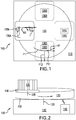
FIG. 1 shows a top view of an apparatus for depowdering a workpiece according to an embodiment; -
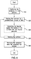
FIG. 2 shows a side view of the apparatus ofFIG. 1 ; -
FIG. 3 shows a side view of an apparatus for depowdering a plurality of printed workpieces according to an embodiment; -
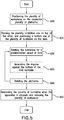
FIG. 4 is a flowchart showing a method of depowdering a workpiece with the apparatus ofFIGS. 1 and 2 according to an embodiment; and -
FIG. 5 is a flowchart showing a method of depowdering a plurality of workpieces with the apparatus ofFIG. 3 according to an embodiment. - A detailed description of one or more embodiments of the disclosed apparatus and method are presented herein by way of exemplification and not limitation with reference to the Figures.
- A challenge in printing workpieces with a laser powder bed fusion (LPBF) process is removing unused powder which remains effectively trapped inside the printed workpiece. To remove unused powder from the printed workpiece, it is desirable to break static friction forces between the unused powder and the printed workpiece, and to impart sufficient transferring forces to remove or convey the unused powder away from the workpiece.
- Turning to
FIGS. 1 and 2 , disclosed is anapparatus 100 for depowdering aworkpiece 105A printed using a LPBF process. Theapparatus 100 includes abase 110, which is a stationary structure such as a machine stand or other table. The apparatus also includes aturntable 120 that is configured to rotate on thebase 110. For example, theturntable 120 is connected to thebase 110 by a motorized spindle 125 (illustrated schematically). - The apparatus also includes a
platform 130A configured to receive theworkpiece 105A and to rotate on theturntable 120. In one embodiment instead oneplatform 130A, there are a plurality of platforms, such as fourplatforms 130A-130D (FIG. 1 ) distributed clockwise about theturntable 120. Theplatforms 130A-130D may be similarly configured in thesystem 100. In addition, each may seat arespective workpiece 105A-105D (where 105B-105D are illustrated schematically inFIG. 1 ). Thus reference to features ofplatform 130A andworkpiece 105A may be interpreted as applying to eachplatform 130A-130D and eachworkpiece 105A-105D. As illustrated, theplatform 130A is connected to theturntable 120 by another motorized spindle 135 (illustrated schematically). - The
turntable 120 may rotate in the direction R1 to depowder theworkpiece 105A. As illustrated, in one embodiment theturntable 120 is configured to rotate in the direction R1 which may be counterclockwise and theplatform 130 is configured to rotate in the direction R2 which may be clockwise, but such rotational motion is not intended to be limiting. For example, in one embodiment theturntable 120 is configured to rotate clockwise and theplatform 130 is configured to rotate counterclockwise. In one embodiment theturntable 120 and theplatform 130 are configured to rotate clockwise. Further in one embodiment theturntable 120 and theplatform 130 are configured to rotate counterclockwise. - As illustrated in
FIG. 1 with rotation of theturntable 120 generates, a rotational force F1 from rotation R1 which may be resolved into tangential force F11 as well as outward force F12. These forces, when generated by theturntable 120, are used to convey unused powder away from the workpiece. - In order to change the distribution of the force F1 about the
workpiece 105A, theplatform 130A may be rotated, for example, incrementally, such as but not limited to one degree, ninety degrees, or by any amount. Such rotation will reorient the rotational forces F1 against theworkpiece 105A and all powder thereon, improving an ability to depowder theworkpiece 105A. - In one embodiment the
apparatus 100 includes an impulse generator 140 (illustrated schematically), which may be installed in thebase 110. Theimpulse generator 140 is configured to generate an impulse against theturntable 120 when theturntable 120 is rotating. When theimpulse generator 140 generates an impulse, static friction forces acting on the unused powder may be broken, thereby increasing the effectiveness of the transferring forces and enabling more efficient depowdering of theworkpiece 105. In one embodiment theimpulse generator 140 is configured to generate the impulse against abottom 150 of theturntable 120. The generator can be an automatic hammer such as a pneumatic hammer. - In one embodiment rather than automatically rotating the
platform 130A, theplatform 130A may be rotationally fixed to theturntable 120 by a latch or pin which may be released to manually rotate theplatform 130A. It is to be appreciated that the action of theplatform 130A andimpulse generator 140 may improve an ability to depowder theworkpiece 105A relative to an embodiment without such implements. However, an embodiment without such implements is within the scope of the disclosure. That is, such embodiment would apply the rotational forces F1 to theworkpiece 105A due to rotation R1 of the turntable, thus depowder theworkpiece 105A. - Turning to
FIG. 3 , in one embodiment theapparatus 101, which may be the same asapparatus 100 except as indicated herein, includes a plurality of turntables 121. As illustratively shown, the plurality of turntables includes afirst turntable 121A, asecond turntable 121B, and athird turntable 121C. Of course, a different configuration or number of turntables 121 could be provided. The plurality of turntables 121 is configured for being stacked one on top of the other. Each of the plurality of turntables 121 is configured to rotate relative to thebase 110. For example, the plurality of turntables 121 is connected to thebase 110 by the motorized spindle 126 (illustrated schematically). - Each of the turntables 121 may be similarly configured and each may be configured similarly to
turntable 120. For example, each may contain four platforms generally referred to as 131 distributed clockwise thereon including platforms 131A1-131A4 onturntable 121A, platforms 131B1-131B4 onplatform 121B and platforms 131C1-131C4 onturntable 121C (each of platforms 131A4, 131B4 and 131C4 is illustrated schematically). The plurality of platforms 131 may be connected to rotate against the respective turntables 121 by a respective plurality of motorized spindles 136. The plurality of motorized spindles 136 includes a first spindle 136A, a second spindle 136B and a third spindle 136C. The plurality of platforms 131 is configured to receive one of a respective plurality of workpieces 106, for example, including workpiece 106A1-106A4 on platform 131A1-131A4, workpieces 106B1-106B4 on platforms 131B1-131B4 and workpiece 106C1-106C4 on platforms 131C1-131C4 (each of workpieces 106A4, 106B4 and 106C4 is illustrated schematically). - In one embodiment, the plurality of turntables 121 may rotate along axis R1 (
FIG. 1 ) to depowder the plurality of workpieces 106. In one embodiment the plurality of turntables 121 is configured to rotate counterclockwise and the plurality of platforms 131 is configured to rotate clockwise, but such rotational motion is not intended to be limiting. For example, in one embodiment the plurality of turntables 121 is configured to rotate clockwise and the plurality of platforms 131 is configured to rotate counterclockwise. In one embodiment the plurality of turntables 121 and the plurality of platforms 131 are configured to rotate clockwise. Further in one embodiment the plurality of turntables 121 and the plurality of platforms 131 are configured to rotate counterclockwise. - In one embodiment the
apparatus 100 illustrated inFIG. 3 also includes the impulse generator 140 (illustrated schematically), which may be installed in thebase 110. Theimpulse generator 140 is configured to generate an impulse against at least one of the plurality of turntables 121 when the plurality of turntables 121 are rotating. When theimpulse generator 140 generates an impulse, unused and loosened powder may be thereby broken from the plurality of workpieces 106, enabling more efficient depowdering of the plurality of workpieces 106. In one embodiment theimpulse generator 140 is configured to generate the impulse against abottom 150 of thefirst turntable 121A, which is a bottom-most one of the turntables 121. In one embodiment theimpulse generator 140 is an automatic hammer. In one embodiment the automatic hammer is a pneumatic hammer. - In one embodiment rather than automatically rotating the plurality of platforms 131, the platforms 131 may be rotationally fixed to the turntable 121 by respective latches or pins which may be released to manually rotate the plurality of platforms 131. It is to be appreciated that the action of the platforms 131 and
impulse generator 140 may improve an ability to depowder the workpiece 106 relative to an embodiment without such implements. However, an embodiment without such implements is within the scope of the disclosure. That is, as withFIG. 1 , such embodiment would apply the rotational forces F1 to the workpieces 106 due to rotation R1 of the turntables 121, thus depowder the workpieces 106. - Turning to
FIG. 4 , a flowchart shows a method of depowdering aworkpiece 105A printed from an LPBF process.Block 510 shows that the method includes positioning theworkpiece 105A on theplatform 130A of the apparatus 100 (FIGS. 1-2 ).Block 520 shows that the method includes rotating theturntable 120 for a predetermined period of time to loosen unused powder from theworkpiece 105. As shown inblock 525, the method may optionally include generating the impulse against thebottom 150 of theturntable 120 with theimpulse generator 140 while theturntable 120 is rotating. The impulse generator breaks unused powered from theworkpiece 105A and may more effectively remove unused powder.Block 530 shows that the method includes rotating the platform 120A, to change an orientation of theworkpiece 105 on theturntable 120, to thereby change a distribution of rotational forces applied when rotating theturntable 120. As indicated, this enhances a removal of unused powder from theworkpiece 105. The portion of the processes illustrated in blocks 520-530 may be repeated to continue to remove unused powder from theworkpiece 105A.Block 540 shows that the method includes removing theworkpiece 105A from theplatform 130 when theapparatus 100 has stopped. - Turning to
FIG. 5 , a flowchart shows a method of depowdering the plurality of workpieces 106 printed from an LPBF process.Block 610 shows that the method includes positioning the plurality of workpieces 106 on the respective plurality of platforms 131 of the apparatus 101 (FIG. 4 ).Block 620 shows that the method includes stacking the plurality of turntables 121 one on top of the other, with thefirst turntable 121A, being the bottom-most turntable, positioned against thebase 110.Block 630 shows that the method includes rotating the plurality of turntables 121 for a predetermined period of time. This loosens unused powder from the respective plurality of workpieces 106. As shown inblock 635 the method may optionally include generating the impulse against thebottom 150 of thefirst turntable 121A with theimpulse generator 140 while the plurality of turntables 121 are rotating. This breaks unused powder from the plurality of workpieces 106.Block 640 shows that the method further includes rotating the plurality of platforms 131, to change an orientation of the workpieces 106 on the turntables 121, to thereby change a distribution of rotational forces applied when rotation the turntables 121. As indicated, this enhances a removal of unused powder from the plurality of workpieces 106. The portion of the processes illustrated in blocks 630-640 may be repeated to continue to remove unused powder from the workpiece 106. 121.Block 650 shows that the method includes unstacking the plurality of turntables 121 when theapparatus 101 is stopped, and removing the plurality of workpieces 106 from the plurality of platforms 131. - The terminology used herein is for the purpose of describing particular embodiments only and is not intended to be limiting of the present disclosure. As used herein, the singular forms "a", "an" and "the" are intended to include the plural forms as well, unless the context clearly indicates otherwise. It will be further understood that the terms "comprises" and/or "comprising," when used in this specification, specify the presence of stated features, integers, steps, operations, elements, and/or components, but do not preclude the presence or addition of one or more other features, integers, steps, operations, element components, and/or groups thereof.
- While the present disclosure has been described with reference to an exemplary embodiment or embodiments, it will be understood by those skilled in the art that various changes may be made and equivalents may be substituted for elements thereof without departing from the scope of the invention as defined by the claims. In addition, many modifications may be made to adapt a particular situation or material to the teachings of the present disclosure without departing from the scope of the invention. Therefore, it is intended that the present disclosure not be limited to the particular embodiment disclosed as the best mode contemplated for carrying out this present disclosure, but that the present disclosure will include all embodiments falling within the scope of the claims.
Claims (15)
- An apparatus for depowdering a workpiece printed from a laser powder bed fusion process, comprising:a base (110);a turntable (120) that rotates relative to the base, the turntable configured to receive the workpiece (105A); andin operation, when the turntable is rotating, rotational forces applied to the workpiece depowder the workpiece.
- The apparatus of claim 1, comprising at platform (130A) disposed on the turntable and configured to receive the workpiece; and in operation, the platform rotates to reorient the rotational forces applied to the workpiece.
- The apparatus of claim 1, comprising a plurality of turntables (121) configured for being stacked one on top of the other, configured to receive a respective one of a plurality of workpieces, and in operation, when the plurality of turntables is rotating, rotational forces applied to the plurality of workpieces depowder the plurality of workpieces.
- The apparatus of claim 3, comprising at least one platform (130A - 130D) disposed on one or more of the turntables and configured to receive the workpieces, and in operation, the at least one platform rotates to reorient the rotational forces applied to the workpieces.
- The apparatus of any preceding claim, comprising an impulse generator (140) configured to generate an impulse against the turntable or the plurality of turntables, wherein when the turntable rotates/turntables rotate, the impulse generator generates the impulse and unused powder is thereby broken from the workpiece(s).
- The apparatus of claim 5, wherein the impulse generator is configured to generate the impulse against a bottom of the turntable or, for a plurality of turntables, wherein the impulse generator is configured to generate the impulse against a bottom of a bottom-most one of the plurality of turntables.
- The apparatus of claim 5 or 6, wherein the impulse generator is a hammer.
- A method of depowdering a workpiece printed from a laser powder bed fusion process, comprising:positioning the workpiece on a turntable of an apparatus, the turntable being configured to rotate on a base of the apparatus; androtating the turntable, thereby applying rotational forces to the workpiece to depowder the workpiece.
- The method of claim 8, comprising positioning the workpiece on a platform that is configured to rotate on the turntable, and turning the platform to reorient the rotational forces applied to the workpiece.
- The method of claim 8, comprising generating an impulse against the turntable with an impulse generator of the apparatus when the turntable is rotating to thereby break unused powder from the workpiece, and optionally comprising generating the impulse against a bottom of the turntable.
- A method of depowdering a plurality of workpieces printed from laser powder bed fusion process, comprising:positioning the plurality of workpieces on a respective plurality turntables of an apparatus;stacking the plurality of turntables one on top of the other, and positioning a bottom one of the plurality of turntables on a base of the apparatus; androtating the plurality of turntables relative to the base, thereby applying rotational forces to the plurality of workpieces to depowder the plurality of workpieces.
- The method of claim 11, comprising distributing the plurality of workpieces on a plurality of platforms that is configured to rotate on plurality of the turntables, and turning the plurality of platforms to reorient the rotational forces applied to the plurality of workpieces.
- The method of claim 11 or 12, comprising generating an impulse against at least one of the plurality of turntables with an impulse generator of the apparatus when the plurality of turntables are rotating.
- The method of claim 13, comprising generating the impulse against a bottom of one of the plurality of turntables.
- The method of any of claims 8 to 14, comprising generating the impulse with a hammer.
Applications Claiming Priority (1)
| Application Number | Priority Date | Filing Date | Title |
|---|---|---|---|
| US16/528,203 US11433614B2 (en) | 2019-07-31 | 2019-07-31 | Apparatus and method for removing unused powder from a printed workpiece |
Publications (1)
| Publication Number | Publication Date |
|---|---|
| EP3771507A1 true EP3771507A1 (en) | 2021-02-03 |
Family
ID=68848012
Family Applications (1)
| Application Number | Title | Priority Date | Filing Date |
|---|---|---|---|
| EP19214759.3A Pending EP3771507A1 (en) | 2019-07-31 | 2019-12-10 | Apparatus and method for removing unused powder from a printed workpiece |
Country Status (2)
| Country | Link |
|---|---|
| US (1) | US11433614B2 (en) |
| EP (1) | EP3771507A1 (en) |
Families Citing this family (1)
| Publication number | Priority date | Publication date | Assignee | Title |
|---|---|---|---|---|
| EP4159331B1 (en) * | 2021-09-29 | 2024-05-22 | Solukon Ingenieure GbR | Cleaning device with oscillating object holder |
Citations (5)
| Publication number | Priority date | Publication date | Assignee | Title |
|---|---|---|---|---|
| EP3257607A1 (en) * | 2016-06-13 | 2017-12-20 | Siemens Aktiengesellschaft | Apparatus for additive manufacturing and use of the apparatus |
| CN207224605U (en) * | 2017-09-15 | 2018-04-13 | 四川梦之兰文化传媒有限公司 | Remove powder device suitable for 3D prints model |
| WO2019023120A1 (en) * | 2017-07-26 | 2019-01-31 | 3M Innovative Properties Company | A method of making a physical object by additive manufacturing |
| CN109732086A (en) * | 2019-01-15 | 2019-05-10 | 上海汉邦联航激光科技有限公司 | Powder removal and recovery device for 3D printed products |
| CN208840516U (en) * | 2018-09-21 | 2019-05-10 | 天津镭明激光科技有限公司 | A post-processing module of an additive manufacturing laser forming system integrated equipment |
Family Cites Families (23)
| Publication number | Priority date | Publication date | Assignee | Title |
|---|---|---|---|---|
| US3503157A (en) * | 1967-02-01 | 1970-03-31 | John F Harper | Orbital barrel finishing machine |
| US4308693A (en) * | 1979-02-21 | 1982-01-05 | Harper Buffing Machine Co. | Barrel-finishing apparatus |
| US4776135A (en) * | 1987-01-15 | 1988-10-11 | Elwood F. Thum, III | System for deburring of articles |
| US5355638A (en) * | 1992-09-08 | 1994-10-18 | Hoffman Steve E | Traction drive centrifugal finisher |
| US20030152659A1 (en) * | 2002-02-08 | 2003-08-14 | Mccloskey Kristin A. | Children's toy for making confections |
| US20040047994A1 (en) * | 2002-09-09 | 2004-03-11 | Robert Becker | Method and apparatus for the removal of excess coating material from a honeycomb body |
| DE112004000301B4 (en) * | 2003-02-25 | 2010-05-20 | Panasonic Electric Works Co., Ltd., Kadoma-shi | Method and device for producing a three-dimensional object |
| JP4267624B2 (en) * | 2003-08-07 | 2009-05-27 | 株式会社日立国際電気 | Substrate processing apparatus and semiconductor device manufacturing method |
| WO2007013240A1 (en) * | 2005-07-27 | 2007-02-01 | Shofu Inc. | Apparatus for forming layered object |
| US20090283119A1 (en) * | 2008-05-16 | 2009-11-19 | Khalil Moussa | Post-Processing System For Solid Freeform Fabrication Parts |
| DE102013223407A1 (en) * | 2013-11-15 | 2015-05-21 | Eos Gmbh Electro Optical Systems | Apparatus and method for layering a three-dimensional object and unpacking the finished object |
| US10052738B2 (en) * | 2015-05-18 | 2018-08-21 | United Technologies Corporation | Internal surface finishing apparatus and method |
| US10913206B2 (en) * | 2015-08-03 | 2021-02-09 | Delavan, Inc | Systems and methods for post additive manufacturing processing |
| EP3167980A1 (en) * | 2015-11-13 | 2017-05-17 | SLM Solutions Group AG | Unpacking device allowing residual raw material powder removal |
| GB201600629D0 (en) | 2016-01-13 | 2016-02-24 | Renishaw Plc | Powder bed fusion apparatus and methods |
| US10583606B2 (en) | 2016-02-11 | 2020-03-10 | General Electric Company | Method and supports with powder removal ports for additive manufacturing |
| WO2018111240A1 (en) * | 2016-12-13 | 2018-06-21 | Statasys, Inc. | Rotary silo additive manufacturing system |
| US11123924B2 (en) * | 2017-02-21 | 2021-09-21 | Renishaw Plc | Powder bed fusion apparatus and methods |
| EP3706941A1 (en) | 2017-11-10 | 2020-09-16 | General Electric Company | Methods for removing loose particles from an object built by additive manufacturing |
| US11072117B2 (en) * | 2017-11-27 | 2021-07-27 | Arcam Ab | Platform device |
| US11541600B2 (en) * | 2018-03-20 | 2023-01-03 | Carbon, Inc. | Rapid wash carrier platform for additive manufacturing of dental models |
| EP3727711B1 (en) * | 2018-04-23 | 2021-07-28 | Carbon, Inc. | Method and resin extractor for additive manufacturing |
| DE102018119027A1 (en) * | 2018-08-06 | 2020-02-06 | Kulzer Gmbh | Method of manufacturing a component using stereolithography |
-
2019
- 2019-07-31 US US16/528,203 patent/US11433614B2/en active Active
- 2019-12-10 EP EP19214759.3A patent/EP3771507A1/en active Pending
Patent Citations (5)
| Publication number | Priority date | Publication date | Assignee | Title |
|---|---|---|---|---|
| EP3257607A1 (en) * | 2016-06-13 | 2017-12-20 | Siemens Aktiengesellschaft | Apparatus for additive manufacturing and use of the apparatus |
| WO2019023120A1 (en) * | 2017-07-26 | 2019-01-31 | 3M Innovative Properties Company | A method of making a physical object by additive manufacturing |
| CN207224605U (en) * | 2017-09-15 | 2018-04-13 | 四川梦之兰文化传媒有限公司 | Remove powder device suitable for 3D prints model |
| CN208840516U (en) * | 2018-09-21 | 2019-05-10 | 天津镭明激光科技有限公司 | A post-processing module of an additive manufacturing laser forming system integrated equipment |
| CN109732086A (en) * | 2019-01-15 | 2019-05-10 | 上海汉邦联航激光科技有限公司 | Powder removal and recovery device for 3D printed products |
Also Published As
| Publication number | Publication date |
|---|---|
| US11433614B2 (en) | 2022-09-06 |
| US20210031453A1 (en) | 2021-02-04 |
Similar Documents
| Publication | Publication Date | Title |
|---|---|---|
| CN105142827B (en) | Structure plate and device for increasing material manufacturing | |
| US10603748B2 (en) | Production of a component by selective laser melting | |
| CN106061712B (en) | machine for grinding workpieces customized by additive manufacturing | |
| TWI678274B (en) | Method and production line for making tangible products by layerwise manufacturing | |
| US4755237A (en) | Methods for making cutting tools | |
| US9527165B2 (en) | Powder deposition process utilizing vibratory mechanical energy | |
| US8826511B2 (en) | Spacer wafer for wafer-level camera and method of manufacturing same | |
| KR20180061136A (en) | Selective deposition of powders in laminate manufacturing | |
| JP7303734B2 (en) | Continuous high-speed 3D printing | |
| CN111526978A (en) | Additive manufacturing with overlapping beams | |
| CA2074742A1 (en) | Method and apparatus for fabrication of three-dimensional metal articles by weld deposition | |
| CN103889642A (en) | Method and apparatus for producing a structured surface on an embossing steel roll | |
| US11433614B2 (en) | Apparatus and method for removing unused powder from a printed workpiece | |
| JP7549126B2 (en) | Efficient bulk unfused powder removal system and method | |
| JP2016507005A (en) | Apparatus and method for removing slag | |
| KR102118319B1 (en) | Tapering jig for evenly coating on working blade of tool | |
| EP3437765B1 (en) | Continuous additive manufacture of high pressure turbine | |
| CN102091865A (en) | Arrangement for depositing coating powder on a rotational symmectric body | |
| KR102452559B1 (en) | A Method for layering Diamond Using 3D Printing | |
| JP2011036865A (en) | Method of forming blind hole | |
| JPH03117565A (en) | Multidisc cutter and manufacture thereof | |
| US20220266341A1 (en) | Additive manufacturing system, additive manufacturing method and computer-readable medium | |
| EP3795284B1 (en) | Surface modification of welding wire drive rolls | |
| JPH01140970A (en) | Multi-disk cutter and manufacture thereof | |
| WO2023047940A1 (en) | Method for repairing damaged part |
Legal Events
| Date | Code | Title | Description |
|---|---|---|---|
| PUAI | Public reference made under article 153(3) epc to a published international application that has entered the european phase |
Free format text: ORIGINAL CODE: 0009012 |
|
| STAA | Information on the status of an ep patent application or granted ep patent |
Free format text: STATUS: THE APPLICATION HAS BEEN PUBLISHED |
|
| AK | Designated contracting states |
Kind code of ref document: A1 Designated state(s): AL AT BE BG CH CY CZ DE DK EE ES FI FR GB GR HR HU IE IS IT LI LT LU LV MC MK MT NL NO PL PT RO RS SE SI SK SM TR |
|
| AX | Request for extension of the european patent |
Extension state: BA ME |
|
| STAA | Information on the status of an ep patent application or granted ep patent |
Free format text: STATUS: REQUEST FOR EXAMINATION WAS MADE |
|
| 17P | Request for examination filed |
Effective date: 20210803 |
|
| RBV | Designated contracting states (corrected) |
Designated state(s): AL AT BE BG CH CY CZ DE DK EE ES FI FR GB GR HR HU IE IS IT LI LT LU LV MC MK MT NL NO PL PT RO RS SE SI SK SM TR |
|
| STAA | Information on the status of an ep patent application or granted ep patent |
Free format text: STATUS: EXAMINATION IS IN PROGRESS |
|
| 17Q | First examination report despatched |
Effective date: 20240411 |