EP3771488A1 - Composite particles, composite particles for forming liquid-encapsulating particles, liquid-encapsulating particles, method for producing liquid-encapsulating particles, biocatalyst-containing material, biocatalyst-containing material producing apparatus, and biocatalyst-containing material producing method - Google Patents
Composite particles, composite particles for forming liquid-encapsulating particles, liquid-encapsulating particles, method for producing liquid-encapsulating particles, biocatalyst-containing material, biocatalyst-containing material producing apparatus, and biocatalyst-containing material producing method Download PDFInfo
- Publication number
- EP3771488A1 EP3771488A1 EP20188462.4A EP20188462A EP3771488A1 EP 3771488 A1 EP3771488 A1 EP 3771488A1 EP 20188462 A EP20188462 A EP 20188462A EP 3771488 A1 EP3771488 A1 EP 3771488A1
- Authority
- EP
- European Patent Office
- Prior art keywords
- hydrophobic solid
- solid particle
- degrees
- particles
- hydrophobic
- Prior art date
- Legal status (The legal status is an assumption and is not a legal conclusion. Google has not performed a legal analysis and makes no representation as to the accuracy of the status listed.)
- Granted
Links
Images




Classifications
-
- C—CHEMISTRY; METALLURGY
- C09—DYES; PAINTS; POLISHES; NATURAL RESINS; ADHESIVES; COMPOSITIONS NOT OTHERWISE PROVIDED FOR; APPLICATIONS OF MATERIALS NOT OTHERWISE PROVIDED FOR
- C09D—COATING COMPOSITIONS, e.g. PAINTS, VARNISHES OR LACQUERS; FILLING PASTES; CHEMICAL PAINT OR INK REMOVERS; INKS; CORRECTING FLUIDS; WOODSTAINS; PASTES OR SOLIDS FOR COLOURING OR PRINTING; USE OF MATERIALS THEREFOR
- C09D127/00—Coating compositions based on homopolymers or copolymers of compounds having one or more unsaturated aliphatic radicals, each having only one carbon-to-carbon double bond, and at least one being terminated by a halogen; Coating compositions based on derivatives of such polymers
- C09D127/02—Coating compositions based on homopolymers or copolymers of compounds having one or more unsaturated aliphatic radicals, each having only one carbon-to-carbon double bond, and at least one being terminated by a halogen; Coating compositions based on derivatives of such polymers not modified by chemical after-treatment
- C09D127/12—Coating compositions based on homopolymers or copolymers of compounds having one or more unsaturated aliphatic radicals, each having only one carbon-to-carbon double bond, and at least one being terminated by a halogen; Coating compositions based on derivatives of such polymers not modified by chemical after-treatment containing fluorine atoms
-
- C—CHEMISTRY; METALLURGY
- C08—ORGANIC MACROMOLECULAR COMPOUNDS; THEIR PREPARATION OR CHEMICAL WORKING-UP; COMPOSITIONS BASED THEREON
- C08J—WORKING-UP; GENERAL PROCESSES OF COMPOUNDING; AFTER-TREATMENT NOT COVERED BY SUBCLASSES C08B, C08C, C08F, C08G or C08H
- C08J3/00—Processes of treating or compounding macromolecular substances
- C08J3/12—Powdering or granulating
- C08J3/128—Polymer particles coated by inorganic and non-macromolecular organic compounds
-
- B—PERFORMING OPERATIONS; TRANSPORTING
- B01—PHYSICAL OR CHEMICAL PROCESSES OR APPARATUS IN GENERAL
- B01J—CHEMICAL OR PHYSICAL PROCESSES, e.g. CATALYSIS OR COLLOID CHEMISTRY; THEIR RELEVANT APPARATUS
- B01J13/00—Colloid chemistry, e.g. the production of colloidal materials or their solutions, not otherwise provided for; Making microcapsules or microballoons
- B01J13/02—Making microcapsules or microballoons
- B01J13/04—Making microcapsules or microballoons by physical processes, e.g. drying, spraying
-
- A—HUMAN NECESSITIES
- A01—AGRICULTURE; FORESTRY; ANIMAL HUSBANDRY; HUNTING; TRAPPING; FISHING
- A01N—PRESERVATION OF BODIES OF HUMANS OR ANIMALS OR PLANTS OR PARTS THEREOF; BIOCIDES, e.g. AS DISINFECTANTS, AS PESTICIDES OR AS HERBICIDES; PEST REPELLANTS OR ATTRACTANTS; PLANT GROWTH REGULATORS
- A01N25/00—Biocides, pest repellants or attractants, or plant growth regulators, characterised by their forms, or by their non-active ingredients or by their methods of application, e.g. seed treatment or sequential application; Substances for reducing the noxious effect of the active ingredients to organisms other than pests
- A01N25/26—Biocides, pest repellants or attractants, or plant growth regulators, characterised by their forms, or by their non-active ingredients or by their methods of application, e.g. seed treatment or sequential application; Substances for reducing the noxious effect of the active ingredients to organisms other than pests in coated particulate form
- A01N25/28—Microcapsules or nanocapsules
-
- A—HUMAN NECESSITIES
- A23—FOODS OR FOODSTUFFS; TREATMENT THEREOF, NOT COVERED BY OTHER CLASSES
- A23P—SHAPING OR WORKING OF FOODSTUFFS, NOT FULLY COVERED BY A SINGLE OTHER SUBCLASS
- A23P10/00—Shaping or working of foodstuffs characterised by the products
- A23P10/30—Encapsulation of particles, e.g. foodstuff additives
-
- C—CHEMISTRY; METALLURGY
- C08—ORGANIC MACROMOLECULAR COMPOUNDS; THEIR PREPARATION OR CHEMICAL WORKING-UP; COMPOSITIONS BASED THEREON
- C08J—WORKING-UP; GENERAL PROCESSES OF COMPOUNDING; AFTER-TREATMENT NOT COVERED BY SUBCLASSES C08B, C08C, C08F, C08G or C08H
- C08J3/00—Processes of treating or compounding macromolecular substances
- C08J3/12—Powdering or granulating
- C08J3/126—Polymer particles coated by polymer, e.g. core shell structures
-
- C—CHEMISTRY; METALLURGY
- C08—ORGANIC MACROMOLECULAR COMPOUNDS; THEIR PREPARATION OR CHEMICAL WORKING-UP; COMPOSITIONS BASED THEREON
- C08K—Use of inorganic or non-macromolecular organic substances as compounding ingredients
- C08K3/00—Use of inorganic substances as compounding ingredients
- C08K3/18—Oxygen-containing compounds, e.g. metal carbonyls
- C08K3/20—Oxides; Hydroxides
- C08K3/22—Oxides; Hydroxides of metals
-
- C—CHEMISTRY; METALLURGY
- C08—ORGANIC MACROMOLECULAR COMPOUNDS; THEIR PREPARATION OR CHEMICAL WORKING-UP; COMPOSITIONS BASED THEREON
- C08K—Use of inorganic or non-macromolecular organic substances as compounding ingredients
- C08K3/00—Use of inorganic substances as compounding ingredients
- C08K3/34—Silicon-containing compounds
- C08K3/36—Silica
-
- C—CHEMISTRY; METALLURGY
- C08—ORGANIC MACROMOLECULAR COMPOUNDS; THEIR PREPARATION OR CHEMICAL WORKING-UP; COMPOSITIONS BASED THEREON
- C08K—Use of inorganic or non-macromolecular organic substances as compounding ingredients
- C08K5/00—Use of organic ingredients
- C08K5/04—Oxygen-containing compounds
- C08K5/06—Ethers; Acetals; Ketals; Ortho-esters
-
- C—CHEMISTRY; METALLURGY
- C09—DYES; PAINTS; POLISHES; NATURAL RESINS; ADHESIVES; COMPOSITIONS NOT OTHERWISE PROVIDED FOR; APPLICATIONS OF MATERIALS NOT OTHERWISE PROVIDED FOR
- C09D—COATING COMPOSITIONS, e.g. PAINTS, VARNISHES OR LACQUERS; FILLING PASTES; CHEMICAL PAINT OR INK REMOVERS; INKS; CORRECTING FLUIDS; WOODSTAINS; PASTES OR SOLIDS FOR COLOURING OR PRINTING; USE OF MATERIALS THEREFOR
- C09D127/00—Coating compositions based on homopolymers or copolymers of compounds having one or more unsaturated aliphatic radicals, each having only one carbon-to-carbon double bond, and at least one being terminated by a halogen; Coating compositions based on derivatives of such polymers
- C09D127/02—Coating compositions based on homopolymers or copolymers of compounds having one or more unsaturated aliphatic radicals, each having only one carbon-to-carbon double bond, and at least one being terminated by a halogen; Coating compositions based on derivatives of such polymers not modified by chemical after-treatment
- C09D127/12—Coating compositions based on homopolymers or copolymers of compounds having one or more unsaturated aliphatic radicals, each having only one carbon-to-carbon double bond, and at least one being terminated by a halogen; Coating compositions based on derivatives of such polymers not modified by chemical after-treatment containing fluorine atoms
- C09D127/18—Homopolymers or copolymers of tetrafluoroethene
-
- C—CHEMISTRY; METALLURGY
- C09—DYES; PAINTS; POLISHES; NATURAL RESINS; ADHESIVES; COMPOSITIONS NOT OTHERWISE PROVIDED FOR; APPLICATIONS OF MATERIALS NOT OTHERWISE PROVIDED FOR
- C09D—COATING COMPOSITIONS, e.g. PAINTS, VARNISHES OR LACQUERS; FILLING PASTES; CHEMICAL PAINT OR INK REMOVERS; INKS; CORRECTING FLUIDS; WOODSTAINS; PASTES OR SOLIDS FOR COLOURING OR PRINTING; USE OF MATERIALS THEREFOR
- C09D7/00—Features of coating compositions, not provided for in group C09D5/00; Processes for incorporating ingredients in coating compositions
- C09D7/40—Additives
- C09D7/60—Additives non-macromolecular
- C09D7/61—Additives non-macromolecular inorganic
-
- C—CHEMISTRY; METALLURGY
- C09—DYES; PAINTS; POLISHES; NATURAL RESINS; ADHESIVES; COMPOSITIONS NOT OTHERWISE PROVIDED FOR; APPLICATIONS OF MATERIALS NOT OTHERWISE PROVIDED FOR
- C09D—COATING COMPOSITIONS, e.g. PAINTS, VARNISHES OR LACQUERS; FILLING PASTES; CHEMICAL PAINT OR INK REMOVERS; INKS; CORRECTING FLUIDS; WOODSTAINS; PASTES OR SOLIDS FOR COLOURING OR PRINTING; USE OF MATERIALS THEREFOR
- C09D7/00—Features of coating compositions, not provided for in group C09D5/00; Processes for incorporating ingredients in coating compositions
- C09D7/40—Additives
- C09D7/60—Additives non-macromolecular
- C09D7/61—Additives non-macromolecular inorganic
- C09D7/62—Additives non-macromolecular inorganic modified by treatment with other compounds
-
- C—CHEMISTRY; METALLURGY
- C12—BIOCHEMISTRY; BEER; SPIRITS; WINE; VINEGAR; MICROBIOLOGY; ENZYMOLOGY; MUTATION OR GENETIC ENGINEERING
- C12M—APPARATUS FOR ENZYMOLOGY OR MICROBIOLOGY; APPARATUS FOR CULTURING MICROORGANISMS FOR PRODUCING BIOMASS, FOR GROWING CELLS OR FOR OBTAINING FERMENTATION OR METABOLIC PRODUCTS, i.e. BIOREACTORS OR FERMENTERS
- C12M25/00—Means for supporting, enclosing or fixing the microorganisms, e.g. immunocoatings
- C12M25/16—Particles; Beads; Granular material; Encapsulation
-
- C—CHEMISTRY; METALLURGY
- C12—BIOCHEMISTRY; BEER; SPIRITS; WINE; VINEGAR; MICROBIOLOGY; ENZYMOLOGY; MUTATION OR GENETIC ENGINEERING
- C12N—MICROORGANISMS OR ENZYMES; COMPOSITIONS THEREOF; PROPAGATING, PRESERVING, OR MAINTAINING MICROORGANISMS; MUTATION OR GENETIC ENGINEERING; CULTURE MEDIA
- C12N1/00—Microorganisms; Compositions thereof; Processes of propagating, maintaining or preserving microorganisms or compositions thereof; Processes of preparing or isolating a composition containing a microorganism; Culture media therefor
- C12N1/005—Microorganisms; Compositions thereof; Processes of propagating, maintaining or preserving microorganisms or compositions thereof; Processes of preparing or isolating a composition containing a microorganism; Culture media therefor after treatment of microbial biomass not covered by C12N1/02 - C12N1/08
-
- C—CHEMISTRY; METALLURGY
- C12—BIOCHEMISTRY; BEER; SPIRITS; WINE; VINEGAR; MICROBIOLOGY; ENZYMOLOGY; MUTATION OR GENETIC ENGINEERING
- C12N—MICROORGANISMS OR ENZYMES; COMPOSITIONS THEREOF; PROPAGATING, PRESERVING, OR MAINTAINING MICROORGANISMS; MUTATION OR GENETIC ENGINEERING; CULTURE MEDIA
- C12N1/00—Microorganisms; Compositions thereof; Processes of propagating, maintaining or preserving microorganisms or compositions thereof; Processes of preparing or isolating a composition containing a microorganism; Culture media therefor
- C12N1/14—Fungi; Culture media therefor
- C12N1/16—Yeasts; Culture media therefor
-
- C—CHEMISTRY; METALLURGY
- C12—BIOCHEMISTRY; BEER; SPIRITS; WINE; VINEGAR; MICROBIOLOGY; ENZYMOLOGY; MUTATION OR GENETIC ENGINEERING
- C12N—MICROORGANISMS OR ENZYMES; COMPOSITIONS THEREOF; PROPAGATING, PRESERVING, OR MAINTAINING MICROORGANISMS; MUTATION OR GENETIC ENGINEERING; CULTURE MEDIA
- C12N11/00—Carrier-bound or immobilised enzymes; Carrier-bound or immobilised microbial cells; Preparation thereof
- C12N11/02—Enzymes or microbial cells immobilised on or in an organic carrier
- C12N11/04—Enzymes or microbial cells immobilised on or in an organic carrier entrapped within the carrier, e.g. gel or hollow fibres
-
- C—CHEMISTRY; METALLURGY
- C12—BIOCHEMISTRY; BEER; SPIRITS; WINE; VINEGAR; MICROBIOLOGY; ENZYMOLOGY; MUTATION OR GENETIC ENGINEERING
- C12N—MICROORGANISMS OR ENZYMES; COMPOSITIONS THEREOF; PROPAGATING, PRESERVING, OR MAINTAINING MICROORGANISMS; MUTATION OR GENETIC ENGINEERING; CULTURE MEDIA
- C12N11/00—Carrier-bound or immobilised enzymes; Carrier-bound or immobilised microbial cells; Preparation thereof
- C12N11/02—Enzymes or microbial cells immobilised on or in an organic carrier
- C12N11/08—Enzymes or microbial cells immobilised on or in an organic carrier the carrier being a synthetic polymer
- C12N11/082—Enzymes or microbial cells immobilised on or in an organic carrier the carrier being a synthetic polymer obtained by reactions only involving carbon-to-carbon unsaturated bonds
-
- C—CHEMISTRY; METALLURGY
- C12—BIOCHEMISTRY; BEER; SPIRITS; WINE; VINEGAR; MICROBIOLOGY; ENZYMOLOGY; MUTATION OR GENETIC ENGINEERING
- C12N—MICROORGANISMS OR ENZYMES; COMPOSITIONS THEREOF; PROPAGATING, PRESERVING, OR MAINTAINING MICROORGANISMS; MUTATION OR GENETIC ENGINEERING; CULTURE MEDIA
- C12N11/00—Carrier-bound or immobilised enzymes; Carrier-bound or immobilised microbial cells; Preparation thereof
- C12N11/14—Enzymes or microbial cells immobilised on or in an inorganic carrier
-
- B—PERFORMING OPERATIONS; TRANSPORTING
- B01—PHYSICAL OR CHEMICAL PROCESSES OR APPARATUS IN GENERAL
- B01J—CHEMICAL OR PHYSICAL PROCESSES, e.g. CATALYSIS OR COLLOID CHEMISTRY; THEIR RELEVANT APPARATUS
- B01J8/00—Chemical or physical processes in general, conducted in the presence of fluids and solid particles; Apparatus for such processes
- B01J8/0095—Chemical or physical processes in general, conducted in the presence of fluids and solid particles; Apparatus for such processes in which two different types of particles react with each other
-
- C—CHEMISTRY; METALLURGY
- C08—ORGANIC MACROMOLECULAR COMPOUNDS; THEIR PREPARATION OR CHEMICAL WORKING-UP; COMPOSITIONS BASED THEREON
- C08J—WORKING-UP; GENERAL PROCESSES OF COMPOUNDING; AFTER-TREATMENT NOT COVERED BY SUBCLASSES C08B, C08C, C08F, C08G or C08H
- C08J2327/00—Characterised by the use of homopolymers or copolymers of compounds having one or more unsaturated aliphatic radicals, each having only one carbon-to-carbon double bond, and at least one being terminated by a halogen; Derivatives of such polymers
- C08J2327/02—Characterised by the use of homopolymers or copolymers of compounds having one or more unsaturated aliphatic radicals, each having only one carbon-to-carbon double bond, and at least one being terminated by a halogen; Derivatives of such polymers not modified by chemical after-treatment
- C08J2327/12—Characterised by the use of homopolymers or copolymers of compounds having one or more unsaturated aliphatic radicals, each having only one carbon-to-carbon double bond, and at least one being terminated by a halogen; Derivatives of such polymers not modified by chemical after-treatment containing fluorine atoms
- C08J2327/18—Homopolymers or copolymers of tetrafluoroethylene
-
- C—CHEMISTRY; METALLURGY
- C08—ORGANIC MACROMOLECULAR COMPOUNDS; THEIR PREPARATION OR CHEMICAL WORKING-UP; COMPOSITIONS BASED THEREON
- C08K—Use of inorganic or non-macromolecular organic substances as compounding ingredients
- C08K3/00—Use of inorganic substances as compounding ingredients
- C08K3/18—Oxygen-containing compounds, e.g. metal carbonyls
- C08K3/20—Oxides; Hydroxides
- C08K3/22—Oxides; Hydroxides of metals
- C08K2003/2237—Oxides; Hydroxides of metals of titanium
-
- C—CHEMISTRY; METALLURGY
- C08—ORGANIC MACROMOLECULAR COMPOUNDS; THEIR PREPARATION OR CHEMICAL WORKING-UP; COMPOSITIONS BASED THEREON
- C08K—Use of inorganic or non-macromolecular organic substances as compounding ingredients
- C08K3/00—Use of inorganic substances as compounding ingredients
- C08K3/18—Oxygen-containing compounds, e.g. metal carbonyls
- C08K3/24—Acids; Salts thereof
- C08K3/26—Carbonates; Bicarbonates
- C08K2003/265—Calcium, strontium or barium carbonate
-
- C—CHEMISTRY; METALLURGY
- C08—ORGANIC MACROMOLECULAR COMPOUNDS; THEIR PREPARATION OR CHEMICAL WORKING-UP; COMPOSITIONS BASED THEREON
- C08K—Use of inorganic or non-macromolecular organic substances as compounding ingredients
- C08K2201/00—Specific properties of additives
- C08K2201/002—Physical properties
- C08K2201/003—Additives being defined by their diameter
-
- C—CHEMISTRY; METALLURGY
- C08—ORGANIC MACROMOLECULAR COMPOUNDS; THEIR PREPARATION OR CHEMICAL WORKING-UP; COMPOSITIONS BASED THEREON
- C08K—Use of inorganic or non-macromolecular organic substances as compounding ingredients
- C08K2201/00—Specific properties of additives
- C08K2201/002—Physical properties
- C08K2201/005—Additives being defined by their particle size in general
-
- C—CHEMISTRY; METALLURGY
- C08—ORGANIC MACROMOLECULAR COMPOUNDS; THEIR PREPARATION OR CHEMICAL WORKING-UP; COMPOSITIONS BASED THEREON
- C08K—Use of inorganic or non-macromolecular organic substances as compounding ingredients
- C08K2201/00—Specific properties of additives
- C08K2201/013—Additives applied to the surface of polymers or polymer particles
Definitions
- the present disclosure relates to composite particles, composite particles for forming liquid-encapsulating particles, liquid-encapsulating particles, a method for producing liquid-encapsulating particles, a biocatalyst-containing material, a biocatalyst-containing material producing apparatus, and a biocatalyst-containing material producing method.
- liquid marbles produced by, for example, aphids have been paid attention.
- Aphids are known to remove droplets of honeydew secreted from inside the bodies to outside the nests by coating the surfaces of the droplets with hydrophobic particles, and handle liquids like solids (for example, see Proc. R. Soc. Lond. B (2002) 269, 1211-1215 ).
- a reported technique coats the surfaces of liquid droplets, which are formed of a lotion component, with particles having a specific wettability (a contact angle with water) to form liquid-encapsulating particles (for example, see J. Soc. Cosmet. Chem.
- a proposed particle-shaped adhesive is formed of a liquid droplet-shaped adhesive component, of which surface is coated with hydrophobic particles (for example, see International Publication No. WO 2015/129903 ).
- the present disclosure has an object to provide composite particles that can suppress coalescing of liquid droplets of various kinds of liquids and can form liquid-encapsulating particles having an excellent durability against external forces.
- composite particles include a hydrophobic solid particle A and a hydrophobic solid particle B over the surface of the hydrophobic solid particle A.
- the contact angle CAa of the hydrophobic solid particle A with water is 110 degrees or greater but 180 degrees or less.
- the contact angle CAb of the hydrophobic solid particle B with water is 110 degrees or greater but 180 degrees or less.
- the ratio (d50a/d50b) of the number average particle diameter d50a of the hydrophobic solid particle A to the number average particle diameter d50b of the hydrophobic solid particle B is 10 or greater but 100 or less.
- the coating ratio CR of the composite particles expressed by Formula 1 below is 50% or higher but 500% or lower.
- Coating ratio CR % ⁇ d 50 b / 2 2 4 ⁇ d 50 a / 2 + d 50 b / 2 2 ⁇ X b g / Y b g / ⁇ m 3 / Z b ⁇ m 3 X a g / Y a g / ⁇ m 3 / Z a ⁇ m 3 ⁇ 100
- Xa represents the mass (g) of the hydrophobic solid particle A
- Xb represents the mass (g) of the hydrophobic solid particle B
- Ya represents the density (g/cubic micrometer) of the hydrophobic solid particle A
- Yb represents the density (g/cubic micrometer) of the hydrophobic solid particle B
- Za represents the volume (cubic micrometer) of the hydrophobic solid particle A
- Zb represents the volume (cubic micrometer) of the hydrophobic solid particle B.
- the present disclosure can provide composite particles that can suppress coalescing of liquid droplets of various kinds of liquids and can form liquid-encapsulating particles having an excellent durability against external forces.
- Composite particles of the present disclosure include a hydrophobic solid particle A and a hydrophobic solid particle B.
- Composite particles of the present disclosure include the hydrophobic solid particle A and the hydrophobic solid particle B over the surface of the hydrophobic solid particle A.
- the hydrophobic solid particle A has a contact angle CAa of 110 degrees or greater but 180 degrees or less with water.
- the hydrophobic solid particle B has a contact angle CAb of 110 degrees or greater but 180 degrees or less with water.
- the ratio (d50a/d50b) of the number average particle diameter d50a of the hydrophobic solid particle A to the number average particle diameter d50b of the hydrophobic solid particle B is 10 or greater but 100 or less.
- the coating ratio CR of the composite particles expressed by Formula 1 below is 50% or higher but 500% or lower.
- the composite particles further include other components as needed.
- Coating ratio CR % ⁇ d 50 b / 2 2 4 ⁇ d 50 a / 2 + d 50 b / 2 2 ⁇ X b g / Y b g / ⁇ m 3 / Z b ⁇ m 3 X a g / Y a g / ⁇ m 3 / Z a ⁇ m 3 ⁇ 100
- Xa represents the mass (g) of the hydrophobic solid particle A
- Xb represents the mass (g) of the hydrophobic solid particle B
- Ya represents the density (g/cubic micrometer) of the hydrophobic solid particle A
- Yb represents the density (g/cubic micrometer) of the hydrophobic solid particle B
- Za represents the volume (cubic micrometer) of the hydrophobic solid particle A
- Zb represents the volume (cubic micrometer) of the hydrophobic solid particle B.
- the present inventor has studied particles that suppress coalescing of liquid droplets of various kinds of liquids and have an excellent durability against external forces, and have obtained the following findings.
- liquid droplet-encapsulating particles may be referred to as liquid marbles or liquid-encapsulating particles
- liquid marbles or liquid-encapsulating particles produced only with particles having a large particle diameter have a small contact area between the particles coating the liquid droplets and the liquid droplets, to have the liquid droplets exposed at some positions, leading to a very poor strength against external forces and difficulty with improving durability.
- liquid-encapsulating particles produced only with particles having a small particle diameter have a better durability against external forces, but are easily deformable, leading to a problem that the liquid-encapsulating particles may coalesce with each other due to a capillary phenomenon.
- hydrophobic solid particles A having a greater particle diameter and hydrophobic solid particles B having a smaller particle diameter makes it possible to suppress coalescing of liquid-encapsulating particles.
- composite particles in which the hydrophobic solid particles B are distributed over the surface of the hydrophobic solid particles A can suppress coalescing of liquid-encapsulating particles, can coat the surfaces of liquid droplets of various kinds of liquids, and can form liquid-encapsulating particles having an excellent durability.
- the hydrophobic solid particle B is present over the surface of the hydrophobic solid particle A and coats the surface of the hydrophobic solid particle A.
- the hydrophobic solid particle B coating the surface of the hydrophobic solid particle A means that the hydrophobic solid particle B coats the surface of the hydrophobic solid particle A enough to enable the effect of the present disclosure to be achieved, and that the hydrophobic solid particle B coats the surface of the hydrophobic solid particle A in a manner to satisfy a coating ratio CR described below.
- the surface of the hydrophobic solid particle A means the exposed surface of the hydrophobic solid particle A.
- the hydrophobic solid particle A has a contact angle CAa of 110 degrees or greater but 180 degrees or less with water.
- the hydrophobic solid particle B has a contact angle CAb of 110 degrees or greater but 180 degrees or less with water.
- hydrophobiccity means a contact angle CAa and a contact angle CAb of 90 degrees or greater but 180 degrees or less with water when measured by a method for measuring the contact angles described below.
- the hydrophobic solid particle A has a contact angle CALa of 100 degrees or greater but 180 degrees or less with the solution
- the hydrophobic solid particle B has a contact angle CALb of 100 degrees or greater but 180 degrees or less with the solution. It is preferable that the hydrophobic solid particle A have a contact angle CALa of 100 degrees or greater but 160 degrees or less with the solution containing water in an amount of 15% by mass or greater, and that the hydrophobic solid particle B have a contact angle CALb of 100 degrees or greater but 160 degrees or less with the solution containing water in an amount of 15% by mass or greater.
- the solution is not particularly limited and may be appropriately selected depending on the intended purpose so long as the solution contains water in an amount of 15% by mass or greater.
- Examples of the solution include saline, a cell culture medium, and a glucose solution.
- Other substances that may be contained are not particularly limited and may be appropriately selected depending on the intended purpose. Examples of the substances include a water-soluble compound, a water-insoluble compound, a food additive, and a physiologically active substance.
- water-insoluble compound examples include inorganic fillers such as titanium oxide, activated carbon, zeolite, and silica.
- antioxidants such as L-sodium ascorbate, and a fungicide.
- physiologically active substance examples include: vitamins such as vitamin B1 and folic acid, and amino acids such as arginine and alanine.
- a plate-shaped body obtained by hot-pressing the material constituting the hydrophobic solid particle A or B or a plate-shaped body obtained by casting a dispersion liquid of the material constituting the hydrophobic solid particle A or B over a substrate by a casting method is used as the sample to be measured, and the angle formed between the liquid surface of water and the surface of the plate-shaped body when the water is located in an amount of 10 microliters over the sample with a microsyringe is measured as the contact angle CAa or CAb with the water (according to a known contact angle measuring method ( ⁇ /2 method)).
- the measuring method described above can be used as the method for measuring the contact angles CALa and CALb with the solution.
- the conditions of the hot-pressing when producing the plate-shaped body by hot-pressing the material constituting the hydrophobic solid particle A or B are as follows.
- the plate-shaped body obtained by casting a dispersion liquid of the material constituting the hydrophobic solid particle A or B over a substrate by a casting method is obtained by the hot-pressing described above on a powder of the sample (the material constituting the hydrophobic solid particle) approximately uniformly sprinkled over PTFE (polytetrafluoroethylene, with an average thickness of 200 micrometers) that is punched to have a diameter of 10 mm and set on the powder compacting die in the production of the plate-shaped body by the hot-pressing of the material constituting the hydrophobic solid particle A or B.
- PTFE polytetrafluoroethylene, with an average thickness of 200 micrometers
- the method for approximately uniformly sprinkling the powder of the sample is not particularly limited and may be approximately selected depending on the intended purpose.
- Examples of the method include a method of sprinkling a dry sample powder, and a method of sprinkling a sample dispersion liquid.
- a solvent used in the sample dispersion liquid is not particularly limited and may be appropriately selected depending on the intended purpose. Examples of the solvent include ethanol. When the sample dispersion liquid is used, it is easy to handle a sample having a low bulk density.
- the materials of the hydrophobic solid particle A and the hydrophobic solid particle B of the composite particles may be identified by, for example, gas chromatography (GC-MS), nuclear magnetic resonance (NMR), and infrared spectroscopy (IR) to procure the materials and measure the contact angles CAa and CAb with the water using the procured materials, or the hydrophobic solid particle A and the hydrophobic solid particle B may be isolated from the composite particles to produce the plate-shaped body using the hydrophobic solid particle A or hydrophobic solid particle B isolated and measure the contact angles CAa and CAb with the water. With the water changed to the solution, the measuring method described above can be used as the method for measuring the contact angles CALa and CALb with the solution.
- GC-MS gas chromatography
- NMR nuclear magnetic resonance
- IR infrared spectroscopy
- Examples of the method for isolating the hydrophobic solid particle A and the hydrophobic solid particle B from the composite particles include a method of filtrating a dispersion liquid of the composite particles obtained by adding an alcohol (for example, ethanol and isopropanol) to the composite particles.
- an alcohol for example, ethanol and isopropanol
- ethanol is preferable.
- Ethanol is preferable because of a high volatility that facilitates drying after filtration.
- the ratio (d50a/d50b) of the number average particle diameter d50a of the hydrophobic solid particles A to the number average particle diameter d50b of the hydrophobic solid particles B is 10 or greater but 100 or less.
- the number average particle diameter d50a of the hydrophobic solid particles A and the number average particle diameter d50b of the hydrophobic solid particles B are each the average of longest diameters of ten particles arbitrarily selected from a scanning electron microscopic image of the hydrophobic solid particles A or the hydrophobic solid particles B isolated by the method described above and observed by bulk.
- the ratio (d50a/d50b) of the number average particle diameter d50a of the hydrophobic solid particles A to the number average particle diameter d50b of the hydrophobic solid particles B is 10 or greater but 100 or less, and preferably 30 or greater but 50 or less.
- the ratio (d50a/d50b) of the number average particle diameter d50a of the hydrophobic solid particles A to the number average particle diameter d50b of the hydrophobic solid particles B is 10 or greater but 100 or less, liquid-encapsulating particles excellent in coalescing suppressibility and durability against external forces can be formed.
- the ratio (d50a/d50b) of the number average particle diameter d50a of the hydrophobic solid particles A to the number average particle diameter d50b of the hydrophobic solid particles B is less than 10, it is difficult to form composite particles.
- the ratio (d50a/d50b) of the number average particle diameter d50a of the hydrophobic solid particles A to the number average particle diameter d50b of the hydrophobic solid particles B is greater than 100, it is possible to form the composite particles, but it is difficult to stably produce liquid-encapsulating particles.
- the number average particle diameter d50a of the hydrophobic solid particles A is not particularly limited and may be appropriately selected depending on the intended purpose so long as the effect of the present disclosure can be obtained, and is preferably 0.1 micrometers or greater but 10 micrometers or less, and more preferably 0.5 micrometers or greater but 5 micrometers or less.
- the number average particle diameter d50a of the hydrophobic solid particles A is 0.1 micrometers or greater but 10 micrometers or less, the amount of the hydrophobic solid particles A to be adsorbed to liquid droplets can be increased, making it possible to more stabilize liquid-encapsulating particles described below.
- the number average particle diameter d50b of the hydrophobic solid particles B is not particularly limited and may be appropriately selected depending on the intended purpose so long as the effect of the present disclosure can be achieved, and for example, is preferably 0.01 micrometers or greater but 0.5 micrometers or less and more preferably 0.01 micrometers or greater but 0.05 micrometers or less.
- the number average particle diameter d50b of the hydrophobic solid particles B is 0.01 micrometers or greater but 0.5 micrometers or less, the amount of the hydrophobic solid particles B to be adsorbed to the hydrophobic solid particles A can be increased, making it possible to more stabilize liquid-encapsulating particles described below.
- a coating ratio CR of the composite particles of the present disclosure expressed by Formula 1 below is 50% or higher but 500% or lower.
- Coating ratio CR % ⁇ d 50 b / 2 2 4 ⁇ d 50 a / 2 + d 50 b / 2 2 ⁇ X b g / Y b g / ⁇ m 3 / Z b ⁇ m 3 X a g / Y a g / ⁇ m 3 / Z a ⁇ m 3 ⁇ 100
- Xa represents the mass (g) of the hydrophobic solid particles A
- Xb represents the mass (g) of the hydrophobic solid particles B
- Ya represents the density (g/cubic micrometer) of the hydrophobic solid particles A
- Yb represents the density (g/cubic micrometer) of the hydrophobic solid particles B
- Za represents the volume (cubic micrometer) of the hydrophobic solid particles A
- Zb represents the volume (cubic micrometer) of the hydrophobic solid particles B.
- the mass (g) and the volume (cubic micrometer) may be values per unit particle, but may be values per bulk so long as the mass and the volume of the composite particles used can be obtained on the same basis as the values per bulk.
- the volume of each particle may be the average of the volumes of particles used, or may be the volume of a true sphere calculated assuming that the particle is a true sphere having an obtained number average particle diameter as the diameter.
- the coating ratio means an abundance ratio of the hydrophobic solid particle B present over the surface of the hydrophobic solid particle A.
- the coating ratio CR is obtained in the manner described below.
- the surface area (4 ⁇ (d50a/2+d50b/2) 2 ) of the composite particles is calculated, where (d50a/2+d50b/2), which is the sum of the quotients obtained by dividing the number average particle diameter d50a of the hydrophobic solid particles A and the number average particle diameter d50b of the hydrophobic solid particles B each by 2, is the radius of the composite particles.
- the area over which hydrophobic solid particles B coat the surface of the hydrophobic solid particle A is obtained by multiplying the area of a cross-section Sb of the hydrophobic solid particle B by the number of hydrophobic solid particles B coating one hydrophobic solid particle A, where the cross-section Sb is orthogonal to the line segment connecting the center of the one hydrophobic solid particle A with the center of the hydrophobic solid particle B and includes the center of the hydrophobic solid particle B.
- the area of the cross-section Sb is expressed as ⁇ (d50b/2) 2 , using the number average particle diameter d50b of the hydrophobic solid particles B.
- the number of hydrophobic solid particles B coating one hydrophobic solid particle A can be expressed as ⁇ Xb(g)/Yb(g/ ⁇ m 3 )/Zb(g/ ⁇ m 3 ) ⁇ / ⁇ Xa(g)/Ya(g/ ⁇ m 3 )/Za(g/ ⁇ m 3 ) ⁇ , using the mass Xa, the density Ya, and the volume Za of the hydrophobic solid particle A and the mass Xb, the density Yb, and the volume Zb of the hydrophobic solid particle B.
- FIG. 1A is an exemplary view illustrating an example of the composite particles of the present disclosure.
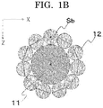
- FIG. 1B is an exemplary view illustrating an example of a cross-section taken in the X-Z plane of FIG. 1A .
- the composite particles 10 of the present disclosure include a hydrophobic solid particle A11 and hydrophobic solid particles B12.
- the hydrophobic solid particles B12 coat the surface of the hydrophobic solid particle A11.
- the coating ratio CR is calculated as the ratio of the area occupied by the hydrophobic solid particles B12 to the surface area of the composite particle 10, where the surface area of the composite particle 10 is calculated based on the number average particle diameter d50a of the hydrophobic solid particles A11 and the number average particle diameter d50b of the hydrophobic solid particles B12.
- the area occupied by the hydrophobic solid particles B12 is obtained by multiplying the area of a cross-section Sb of the hydrophobic solid particle B12 by the number of hydrophobic solid particles B coating one hydrophobic solid particle A11, where the cross-section Sb is orthogonal to the line segment connecting the center of the one hydrophobic solid particle A11 with the center of the hydrophobic solid particle B12 and includes the center of the hydrophobic solid particle B12 as illustrated in FIG 1B .
- the coating ratio CR is 50% or higher but 500% or lower, and preferably 100% or higher but 200% or lower.
- the coating ratio CR is 50% or higher but 500% or lower, liquid-encapsulating particles excellent in coalescing suppressibility and durability against external forces can be formed.
- the coating ratio CR is lower than 50%, the hydrophobic solid particles A dominantly contact the water or the solution, making it difficult to obtain the effect of suppressing coalescing.
- the hydrophobic solid particles B aggregate and accumulate over the surface of the hydrophobic solid particles A and dominantly contact the water or the solution, making it difficult to obtain the effect of suppressing coalescing.
- the material of the hydrophobic solid particles A is not particularly limited and may be appropriately selected depending on the intended purpose so long as the material has the contact angle CAa of 110 degrees or greater but 180 degrees or less with the water.
- Examples of the material of the hydrophobic solid particles A include organic materials and inorganic materials.
- organic materials examples include polymer materials.
- Examples of the polymer materials include resins.
- the resins include fluororesins, silicone resins, cellulose, and copolymers containing at least one of these resins.
- fluororesins examples include polytetrafluoroethylene (PTFE), perfluoroalkoxyalkane (PFA), perfluoroethylene propene copolymers (FEP), ethylene tetrafluoroethylene copolymers (ETFE), polyvinylidene fluoride (PVDF), polychlorotrifluoroethylene (PCTFE), and ethylene chlorotrifluoroethylene copolymers (ECTFE).
- PTFE polytetrafluoroethylene
- PFA perfluoroalkoxyalkane
- FEP perfluoroethylene propene copolymers
- ETFE ethylene tetrafluoroethylene copolymers
- PVDF polyvinylidene fluoride
- PCTFE polychlorotrifluoroethylene copolymers
- ECTFE ethylene chlorotrifluoroethylene copolymers
- silicone resins examples include methyl silicone resins and urethane-modified silicone resins.
- examples of the inorganic materials include silica and calcium carbonate.
- silica examples include fumed silica and silica spherical particles (QSG series: available from Shin-Etsu Chemical Co., Ltd.).
- a hydrophobizing treatment may be applied to the surfaces of the organic materials and the inorganic materials. Any of the organic materials and the inorganic materials that do not have hydrophobicity as a material property may be used with hydrophobicity imparted to the surfaces by the hydrophobizing treatment.
- Examples of the organic materials to which the hydrophobizing treatment is applied include hydrophobized starch.
- Examples of the hydrophobized starch include octenylsuccinic acid corn starch ester aluminum (product name: OCTIE, available from Nippon Starch Chemical Co., Ltd.).
- the organic material is hydrophobized, by measuring the contact angle. It is possible to confirm that the organic material is hydrophobized, by measuring the contact angle of a compression-molded (e.g., hot-pressed) sample obtained by the method described above and seeing to it that the contact angle is 90 degrees or greater but 180 degrees or less.
- a compression-molded (e.g., hot-pressed) sample obtained by the method described above and seeing to it that the contact angle is 90 degrees or greater but 180 degrees or less.
- Examples of the inorganic materials to which the hydrophobizing treatment is applied include stearic acid-treated calcium carbonate.
- examples of the stearic acid-treated calcium carbonate include a product obtained by mixing calcium carbonate (100 g) with stearic acid (10 g) and methanol (500 ml), evaporating methanol at reduced pressure, and heating and drying the resultant at 50 degrees C.
- the inorganic material is hydrophobized, by measuring the contact angle.
- the hydrophobizing treatment is a treatment with stearic acid
- it is possible to confirm that the inorganic material is treated with stearic acid by measuring the contact angle of a compression-molded (e.g., hot-pressed) sample and seeing to it that the contact angle is 90 degrees or greater or 180 degrees or less.
- the material of the hydrophobic solid particles B is not particularly limited and may be appropriately selected depending on the intended purpose so long as the material has the contact angle CAb of 110 degrees or greater but 180 degrees or less with the water.
- Examples of the material of the hydrophobic solid particles B include organic materials and inorganic materials.
- organic materials examples include polymer materials.
- Examples of the polymer materials include resins.
- the resins include fluororesins, silicone resins, cellulose, and copolymers containing at least one of these resins.
- fluororesins examples include polytetrafluoroethylene (PTFE), perfluoroalkoxyalkane (PFA), perfluoroethylene propene copolymers (FEP), ethylene tetrafluoroethylene copolymers (ETFE), polyvinylidene fluoride (PVDF), polychlorotrifluoroethylene (PCTFE), and ethylene chlorotrifluoroethylene copolymers (ECTFE).
- PTFE polytetrafluoroethylene
- PFA perfluoroalkoxyalkane
- FEP perfluoroethylene propene copolymers
- ETFE ethylene tetrafluoroethylene copolymers
- PVDF polyvinylidene fluoride
- PCTFE polychlorotrifluoroethylene copolymers
- ECTFE ethylene chlorotrifluoroethylene copolymers
- silicone resins examples include methyl silicone resins and urethane-modified silicone resins.
- examples of the inorganic materials include silica and calcium carbonate.
- silica examples include fumed silica and silica spherical particles (QSG series: available from Shin-Etsu Chemical Co., Ltd.).
- a hydrophobizing treatment may be applied to the surfaces of the organic materials and the inorganic materials. Any of the organic materials and the inorganic materials that do not have hydrophobicity as a material property may be used with hydrophobicity imparted to the surfaces by the hydrophobizing treatment.
- Examples of the organic materials to which the hydrophobizing treatment is applied include hydrophobized starch.
- Examples of the hydrophobized starch include octenylsuccinic acid corn starch ester aluminum (product name: OCTIE, available from Nippon Starch Chemical Co., Ltd.).
- the organic material is hydrophobized, by measuring the contact angle. It is possible to confirm that the organic material is hydrophobized, by measuring the contact angle of a compression-molded (e.g., hot-pressed) sample obtained by the method described above and seeing to it that the contact angle is 100 degrees or greater.
- a compression-molded (e.g., hot-pressed) sample obtained by the method described above and seeing to it that the contact angle is 100 degrees or greater.
- Examples of the inorganic materials to which the hydrophobizing treatment is applied include stearic acid-treated calcium carbonate.
- examples of the stearic acid-treated calcium carbonate include a product obtained by mixing calcium carbonate (100 g) with stearic acid (10 g) and methanol (500 ml), evaporating methanol at reduced pressure, and heating and drying the resultant at 50 degrees C.
- the inorganic material is hydrophobized, by measuring the contact angle.
- the hydrophobizing treatment is a treatment with stearic acid
- it is possible to confirm that the inorganic material is treated with stearic acid by measuring the contact angle of a compression-molded (e.g., hot-pressed) sample and seeing to it that the contact angle is 90 degrees or greater but 180 degrees or less.
- the material of the hydrophobic solid particles B may be the same as or different from the material of the hydrophobic solid particles A so long as the above-described relationship between the hydrophobic solid particles A and the hydrophobic solid particles B according to the present disclosure is satisfied. It is preferable that at least either the hydrophobic solid particle A or the hydrophobic solid particle B be formed of at least one selected from fluororesins, silica, stearic acid-treated calcium carbonate, and hydrophobized starch.
- the shape of the hydrophobic solid particles A and the hydrophobic solid particles B is not particularly limited and may be appropriately selected depending on the intended purpose so long as the shape has a structure that can achieve the effect of the present disclosure.
- Examples of the shape include spherical shapes, true-spherical shapes, flat shapes, acicular shapes, columnar shapes, indefinite shapes, and rectangular parallelepiped shapes.
- the structure of the hydrophobic solid particles A and the hydrophobic solid particles B is not particularly limited and may be appropriately selected depending on the intended purpose so long as the structure can achieve the effect of the present disclosure.
- Examples of the structure include porous structures, hollow structures, and layered structures.
- the other components are not particularly limited and may be appropriately selected depending on the intended purpose.
- Examples of the other components include hydrophobic solid particles other than the hydrophobic solid particles A and the hydrophobic solid particles B that constitute the composite particles, and additives.
- hydrophobic solid particles other than the hydrophobic solid particles A and the hydrophobic solid particles B that constitute the composite particles are not particularly limited and may be appropriately selected depending on the intended purpose so long as the hydrophobic solid particles are hydrophobic solid particles other than the hydrophobic solid particles A and the hydrophobic solid particles B that constitute the composite particles.
- the additives are not particularly limited and may be appropriately selected depending on the intended purpose so long as the additives can achieve the effect of the present disclosure.
- Examples of the additives include zinc stearate.
- the method for producing the composite particles of the present disclosure can obtain the composite particles by feeding the hydrophobic solid particles A and the hydrophobic solid particles B to a mixer under an inert gas and stirring the hydrophobic solid particles A and the hydrophobic solid particles B at 10 rpm for 12 hours.
- a procured powder material may be subjected to dispersion treatment with addition of alcohol (for example, ethanol and isopropanol) to be separated into solid particles A and B, and then isolated by filtration, to measure the mass (g), density (g/cubic micrometer), and volume (cubic micrometer) of the solid particles A and the solid particles B.
- alcohol for example, ethanol and isopropanol
- g mass
- g/cubic micrometer density
- volume volume
- a plate-shaped body obtained by hot-pressing the material constituting the solid particles A or B isolated or a plate-shaped body obtained by casting a dispersion liquid of the solid particles A or B over a substrate by a casting method may be used as the sample to be measured, and the angle formed between water and the smooth surface when the water is located in an amount of 10 microliters over the sample with a microsyringe may be measured as the contact angle CAa or CAb with the water.
- the measuring method described above can be used as the method for measuring the contact angles CALa and CALb with the solution.
- the hot-pressing and the casting method are the same as the methods described above.
- the mass (g) of the solid particles A and the solid particles B is measured with a precision balance.
- the density (g/cubic micrometer) of the solid particles A and the solid particles B is a true density measurement and is measured with a Gay-Lussac type specific gravity bottle (a pycnometer method).
- a Gay-Lussac type specific gravity bottle a pycnometer method.
- catalog values or literature values of the solid particles used may be used.
- the volume (cubic micrometer) of the solid particles A and the solid particles B is calculated from the number average particle diameter.
- Liquid-encapsulating particles of the present disclosure include a liquid droplet, and composite particles including a hydrophobic solid particle A and a hydrophobic solid particle B over the surface of the hydrophobic solid particle A.
- the hydrophobic solid particle A has a contact angle CAa of 110 degrees or greater but 180 degrees or less with water.
- the hydrophobic solid particle B has a contact angle CAb of 110 degrees or greater but 180 degrees or less with water.
- the ratio (d50a/d50b) of the number average particle diameter d50a of the hydrophobic solid particle A to the number average particle diameter d50b of the hydrophobic solid particle B is 10 or greater but 100 or less.
- the coating ratio CR of the composite particles expressed by Formula 1 below is 50% or higher but 500% or lower.
- the surface of the liquid droplet is coated with the composite particles.
- the liquid-encapsulating particles further contain other components as needed.
- Coating ratio CR % ⁇ d 50 b / 2 2 4 ⁇ d 50 a / 2 + d 50 b / 2 2 ⁇ X b g / Y b g / ⁇ m 3 / Z b ⁇ m 3 X a g / Y a g / ⁇ m 3 / Z a ⁇ m 3 ⁇ 100
- Xa represents the mass (g) of the hydrophobic solid particle A
- Xb represents the mass (g) of the hydrophobic solid particle B
- Ya represents the density (g/cubic micrometer) of the hydrophobic solid particle A
- Yb represents the density (g/cubic micrometer) of the hydrophobic solid particle B
- Za represents the volume (cubic micrometer) of the hydrophobic solid particle A
- Zb represents the volume (cubic micrometer) of the hydrophobic solid particle B.
- the liquid-encapsulating particles of the present disclosure include a liquid droplet formed of a solution containing water in an amount of 15% by mass or greater, and composite particles.
- the hydrophobic solid particle A has a contact angle CALa of 100 degrees or greater but 180 degrees or less with the solution
- the hydrophobic solid particle B has a contact angle CALb of 100 degrees or greater but 180 degrees or less with the solution
- the ratio (d50a/d50b) of the number average particle diameter d50a of the hydrophobic solid particle A to the number average particle diameter d50b of the hydrophobic solid particle B is 10 or greater but 100 or less
- the coating ratio CR of the composite particles expressed by Formula 1 below is 50% or higher but 500% or lower.
- the surface of the liquid droplet is coated with the composite particles.
- the liquid-encapsulating particles further contain other components as needed.
- Coating ratio CR % ⁇ d 50 b / 2 2 4 ⁇ d 50 a / 2 + d 50 b / 2 2 ⁇ X b g / Y b g / ⁇ m 3 / Z b ⁇ m 3 X a g / Y a g / ⁇ m 3 / Z a ⁇ m 3 ⁇ 100
- Xa represents the mass (g) of the hydrophobic solid particle A
- Xb represents the mass (g) of the hydrophobic solid particle B
- Ya represents the density (g/cubic micrometer) of the hydrophobic solid particle A
- Yb represents the density (g/cubic micrometer) of the hydrophobic solid particle B
- Za represents the volume (cubic micrometer) of the hydrophobic solid particle A
- Zb represents the volume (cubic micrometer) of the hydrophobic solid particle B.
- the liquid-encapsulating particles of the present disclosure refer to particles that are in a state that the surface of the liquid droplet is coated with the composite particles.
- the state that the surface of the liquid droplet is coated with the composite particles is not particularly limited so long as the surface is coated enough to enable the effect of the present disclosure to be achieved, and the surface may be completely coated or may be partially coated.
- the composite particles are the same as the composite particles of the present disclosure.
- the liquid droplet is one selected from the group consisting of water and a solution containing water in an amount of 15% by mass or greater, and further contains other components as needed.
- the solution is not particularly limited and may be appropriately selected depending on the intended purpose so long as the solution contains water in an amount of 15% by mass or greater.
- Examples of the solution include saline, a cell culture medium, and a glucose solution.
- Other substances that may be contained are not particularly limited and may be appropriately selected depending on the intended purpose. Examples of the substances include a water-soluble compound, a water-insoluble compound, a food additive, and a physiologically active substance.
- EMIM 1-ethyl-3-methyl imidazolium trifluoromethane sulfonate
- BMIM][CF 3 SO 3 ] 1-butyl-3-methyl imidazolium trifluoromethane sulfonate
- glycerin glycerin
- polyglycerin
- water-insoluble compound examples include inorganic fillers such as titanium oxide, activated carbon, zeolite, and silica.
- antioxidants such as L-sodium ascorbate, and a fungicide.
- physiologically active substance examples include vitamins such as vitamin B1 and folic acid, and amino acids such as arginine and alanine.
- the other components are not particularly limited and may be appropriately selected depending on the intended purpose.
- Examples of the other components include a food additive and a physiologically active substance.
- antioxidants such as L-sodium ascorbate, and a fungicide.
- physiologically active substance examples include vitamins such as vitamin B1 and folic acid, and amino acids such as arginine and alanine.
- the number average particle d50c of the liquid-encapsulating particles of the present disclosure is preferably 15 micrometers or greater but 2.5 mm or less, and more preferably 15 micrometers or greater but 1.0 mm or less.
- the number average particle diameter d50c of the liquid-encapsulating particles is 15 micrometers or greater, the liquid-encapsulating particles can be suppressed from drying during production of the liquid droplets, making it possible to efficiently produce the liquid-encapsulating particles.
- the number average particle diameter d50c of the liquid-encapsulating particles is 2.5 mm or less, spontaneous coalescing of the liquid-encapsulating particles and explosion of the liquid-encapsulating particles under the influence of the gravity can be suppressed.
- the method for measuring the number average particle diameter d50c of the liquid-encapsulating particles is not particularly limited and may be appropriately selected depending on the intended purpose. Examples of the method include a method of observing the liquid-encapsulating particles with an optical microscope, measuring the longest diameters of arbitrary ten particles, and averaging the measured values.
- Examples of the method for analyzing the components of the liquid droplet contained in the liquid-encapsulating particles include a method of exposing the liquid-encapsulating particles to ethanol vapor, separating the liquid-encapsulating particles into the liquid (liquid droplet) and the composite particles by filtration, and analyzing the liquid.
- the method for analyzing the liquid is not particularly limited and may be appropriately selected depending on the intended purpose. Examples of the method include liquid chromatography.
- the composite particles for forming liquid-encapsulating particles of the present disclosure are formed of the composite particles of the present disclosure, and include other components as needed.
- the composite particles for forming liquid-encapsulating particles of the present disclosure are the same as the composite particles of the present disclosure.
- the composite particles for forming liquid-encapsulating particles of the present disclosure can be suitably used for the liquid-encapsulating particles of the present disclosure exclusively.
- a method for producing liquid-encapsulating particles of the present disclosure includes a liquid droplet forming step of forming a liquid droplet from a liquid, and a surface coating step of coating the surface of the liquid droplet with composite particles including a hydrophobic solid particle A and a hydrophobic solid particle B over the surface of the hydrophobic solid particle A, wherein a contact angle CAa of the hydrophobic solid particle A with water is 110 degrees or greater but 180 degrees or less, wherein a contact angle CAb of the hydrophobic solid particle B with water is 110 degrees or greater but 180 degrees or less, wherein a ratio (d50a/d50b) of the number average particle diameter d50a of the hydrophobic solid particle A to the number average particle diameter d50b of the hydrophobic solid particle B is 10 or greater but 100 or less, and wherein a coating ratio CR of the composite particles expressed by Formula 1 below is 50% or higher but 500% or lower.
- the method for producing liquid-encapsulating particles further includes other steps as needed.
- Coating ratio CR % ⁇ d 50 b / 2 2 4 ⁇ d 50 a / 2 + d 50 b / 2 2 ⁇ X b g / Y b g / ⁇ m 3 / Z b ⁇ m 3 X a g / Y a g / ⁇ m 3 / Z a ⁇ m 3 ⁇ 100
- Xa represents the mass (g) of the hydrophobic solid particle A
- Xb represents the mass (g) of the hydrophobic solid particle B
- Ya represents the density (g/cubic micrometer) of the hydrophobic solid particle A
- Yb represents the density (g/cubic micrometer) of the hydrophobic solid particle B
- Za represents the volume (cubic micrometer) of the hydrophobic solid particle A
- Zb represents the volume (cubic micrometer) of the hydrophobic solid particle B.
- a method for producing liquid-encapsulating particles of the present disclosure includes a liquid droplet forming step of forming a liquid droplet from a solution containing water in an amount of 15% by mass or greater, and a surface coating step of coating the surface of the liquid droplet with composite particles including a hydrophobic solid particle A and a hydrophobic solid particle B over the surface of the hydrophobic solid particle A, wherein a contact angle CALa of the hydrophobic solid particle A with the solution is 100 degrees or greater but 180 degrees or less, wherein a contact angle CALb of the hydrophobic solid particle B with the solution is 100 degrees or greater but 180 degrees or less, wherein a ratio (d50a/d50b) of the number average particle diameter d50a of the hydrophobic solid particle A to the number average particle diameter d50b of the hydrophobic solid particle B is 10 or greater but 100 or less, and wherein a coating ratio CR of the composite particles expressed by Formula 1 below is 50% or higher but 500% or lower.
- the method for producing liquid-encapsulating particles further includes other steps as needed.
- Coating ratio CR % ⁇ d 50 b / 2 2 4 ⁇ d 50 a / 2 + d 50 b / 2 2 ⁇ X b g / Y b g / ⁇ m 3 / Z b ⁇ m 3 X a g / Y a g / ⁇ m 3 / Z a ⁇ m 3 ⁇ 100
- Xa represents the mass (g) of the hydrophobic solid particle A
- Xb represents the mass (g) of the hydrophobic solid particle B
- Ya represents the density (g/cubic micrometer) of the hydrophobic solid particle A
- Yb represents the density (g/cubic micrometer) of the hydrophobic solid particle B
- Za represents the volume (cubic micrometer) of the hydrophobic solid particle A
- Zb represents the volume (cubic micrometer) of the hydrophobic solid particle B.
- An apparatus for producing liquid-encapsulating particles of the present disclosure includes a liquid droplet forming unit configured to form a liquid droplet from a liquid, and a surface coating unit configured to coat the surface of the liquid droplet with composite particles including a hydrophobic solid particle A and a hydrophobic solid particle B over the surface of the hydrophobic solid particle A, wherein a contact angle CAa of the hydrophobic solid particle A with water is 110 degrees or greater but 180 degrees or less, wherein a contact angle CAb of the hydrophobic solid particle B with water is 110 degrees or greater but 180 degrees or less, wherein a ratio (d50a/d50b) of the number average particle diameter d50a of the hydrophobic solid particle A to the number average particle diameter d50b of the hydrophobic solid particle B is 10 or greater but 100 or less, and wherein a coating ratio CR of the composite particles expressed by Formula 1 below is 50% or higher but 500% or lower.
- the apparatus for producing liquid-encapsulating particles further includes other units as needed.
- Coating ratio CR % ⁇ d 50 b / 2 2 4 ⁇ d 50 a / 2 + d 50 b / 2 2 ⁇ X b g / Y b g / ⁇ m 3 / Z b ⁇ m 3 X a g / Y a g / ⁇ m 3 / Z a ⁇ m 3 ⁇ 100
- Xa represents the mass (g) of the hydrophobic solid particle A
- Xb represents the mass (g) of the hydrophobic solid particle B
- Ya represents the density (g/cubic micrometer) of the hydrophobic solid particle A
- Yb represents the density (g/cubic micrometer) of the hydrophobic solid particle B
- Za represents the volume (cubic micrometer) of the hydrophobic solid particle A
- Zb represents the volume (cubic micrometer) of the hydrophobic solid particle B.
- An apparatus for producing liquid-encapsulating particles of the present disclosure includes a liquid droplet forming unit configured to form a liquid droplet from a solution containing water in an amount of 15% by mass or greater, and a surface coating unit configured to coat the surface of the liquid droplet with composite particles including a hydrophobic solid particle A and a hydrophobic solid particle B over the surface of the hydrophobic solid particle A, wherein a contact angle CALa of the hydrophobic solid particle A with the solution is 100 degrees or greater but 180 degrees or less, wherein a contact angle CALb of the hydrophobic solid particle B with the solution is 100 degrees or greater but 180 degrees or less, wherein a ratio (d50a/d50b) of the number average particle diameter d50a of the hydrophobic solid particle A to the number average particle diameter d50b of the hydrophobic solid particle B is 10 or greater but 100 or less, and wherein a coating ratio CR of the composite particles expressed by Formula 1 below is 50% or higher but 500% or lower.
- the apparatus for producing liquid-encapsulating particles further includes other units as needed.
- Coating ratio CR % ⁇ d 50 b / 2 2 4 ⁇ d 50 a / 2 + d 50 b / 2 2 ⁇ X b g / Y b g / ⁇ m 3 / Z b ⁇ m 3 X a g / Y a g / ⁇ m 3 / Z a ⁇ m 3 ⁇ 100
- Xa represents the mass (g) of the hydrophobic solid particle A
- Xb represents the mass (g) of the hydrophobic solid particle B
- Ya represents the density (g/cubic micrometer) of the hydrophobic solid particle A
- Yb represents the density (g/cubic micrometer) of the hydrophobic solid particle B
- Za represents the volume (cubic micrometer) of the hydrophobic solid particle A
- Zb represents the volume (cubic micrometer) of the hydrophobic solid particle B.
- the method for producing liquid-encapsulating particles of the present disclosure can be suitably performed using the apparatus for producing liquid-encapsulating particles.
- the liquid droplet forming step can be suitably performed by the liquid droplet forming unit.
- the surface coating step can be suitably performed by the surface coating unit.
- the liquid droplet forming step is a step of forming a liquid droplet from a liquid.
- the liquid droplet forming unit is a unit configured to form a liquid droplet from a liquid.
- the liquid droplet forming step can be suitably performed by the liquid droplet forming unit.
- the liquid is not particularly limited and may be appropriately selected depending on the intended purpose.
- Examples of the liquid include water and a solution containing water in an amount of 15% by mass or greater.
- the liquid is not particularly limited and may be appropriately selected depending on the intended purpose so long as the liquid contains water in an amount of 15% by mass or greater.
- the liquid include saline, a cell culture medium, and a glucose solution.
- Other substances that may be contained are not particularly limited and may be appropriately selected depending on the intended purpose. Examples of the substances include a water-soluble compound, a water-insoluble compound, a food additive, and a physiologically active substance.
- EMIM 1-ethyl-3-methyl imidazolium trifluoromethane sulfonate
- BMIM][CF 3 SO 3 ] 1-butyl-3-methyl imidazolium trifluoromethane sulfonate
- glycerin glycerin
- polyglycerin
- water-insoluble compound examples include inorganic fillers such as titanium oxide, activated carbon, zeolite, and silica.
- antioxidants such as L-sodium ascorbate, and a fungicide.
- physiologically active substance examples include: vitamins such as vitamin B1 and folic acid, and amino acids such as arginine and alanine.
- a known liquid droplet forming unit can be used as the liquid droplet forming unit.
- the liquid droplet forming unit is not particularly limited and may be appropriately selected depending on the intended purpose so long as the liquid droplet forming unit can form a liquid droplet from a liquid.
- Examples of the liquid droplet forming unit include an inkjet type, a dispenser type, and a spray drying type.
- the dispenser type is preferable because the dispenser type is versatile with a broad range of liquid properties that can be formed into a liquid droplet and can control the size of a liquid droplet by the size of the pore diameter of the head and the pressure for pushing out the liquid filled.
- the surface coating step is a step of coating the surface of the liquid droplet with composite particles including a hydrophobic solid particle A and a hydrophobic solid particle B over the surface of the hydrophobic solid particle A, wherein a contact angle CAa of the hydrophobic solid particle A with water is 110 degrees or greater but 180 degrees or less, wherein a contact angle CAb of the hydrophobic solid particle B with water is 110 degrees or greater but 180 degrees or less, wherein a ratio (d50a/d50b) of the number average particle diameter d50a of the hydrophobic solid particle A to the number average particle diameter d50b of the hydrophobic solid particle B is 10 or greater but 100 or less, and wherein a coating ratio CR of the composite particles expressed by Formula 1 below is 50% or higher but 500% or lower.
- Coating ratio CR % ⁇ d 50 b / 2 2 4 ⁇ d 50 a / 2 + d 50 b / 2 2 ⁇ X b g / Y b g / ⁇ m 3 / Z b ⁇ m 3 X a g / Y a g / ⁇ m 3 / Z a ⁇ m 3 ⁇ 100
- Xa represents the mass (g) of the hydrophobic solid particle A
- Xb represents the mass (g) of the hydrophobic solid particle B
- Ya represents the density (g/cubic micrometer) of the hydrophobic solid particle A
- Yb represents the density (g/cubic micrometer) of the hydrophobic solid particle B
- Za represents the volume (cubic micrometer) of the hydrophobic solid particle A
- Zb represents the volume (cubic micrometer) of the hydrophobic solid particle B.
- the surface coating unit is a unit configured to coat the surface of the liquid droplet with composite particles including a hydrophobic solid particle A and a hydrophobic solid particle B over the surface of the hydrophobic solid particle A, wherein a contact angle CAa of the hydrophobic solid particle A with water is 110 degrees or greater but 180 degrees or less, wherein a contact angle CAb of the hydrophobic solid particle B with water is 110 degrees or greater but 180 degrees or less, wherein a ratio (d50a/d50b) of the number average particle diameter d50a of the hydrophobic solid particle A to the number average particle diameter d50b of the hydrophobic solid particle B is 10 or greater but 100 or less, and wherein a coating ratio CR of the composite particles expressed by Formula 1 below is 50% or higher but 500% or lower.
- Coating ratio CR % ⁇ d 50 b / 2 2 4 ⁇ d 50 a / 2 + d 50 b / 2 2 ⁇ X b g / Y b g / ⁇ m 3 / Z b ⁇ m 3 X a g / Y a g / ⁇ m 3 / Z a ⁇ m 3 ⁇ 100
- Xa represents the mass (g) of the hydrophobic solid particle A
- Xb represents the mass (g) of the hydrophobic solid particle B
- Ya represents the density (g/cubic micrometer) of the hydrophobic solid particle A
- Yb represents the density (g/cubic micrometer) of the hydrophobic solid particle B
- Za represents the volume (cubic micrometer) of the hydrophobic solid particle A
- Zb represents the volume (cubic micrometer) of the hydrophobic solid particle B.
- the surface coating step is a step of coating the surface of the liquid droplet with composite particles including a hydrophobic solid particle A and a hydrophobic solid particle B over the surface of the hydrophobic solid particle A, wherein a contact angle CALa of the hydrophobic solid particle A with the solution is 100 degrees or greater but 180 degrees or less, wherein a contact angle CALb of the hydrophobic solid particle B with the solution is 100 degrees or greater but 180 degrees or less, wherein a ratio (d50a/d50b) of the number average particle diameter d50a of the hydrophobic solid particle A to the number average particle diameter d50b of the hydrophobic solid particle B is 10 or greater but 100 or less, and wherein a coating ratio CR of the composite particles expressed by Formula 1 below is 50% or higher but 500% or lower.
- Coating ratio CR % ⁇ d 50 b / 2 2 4 ⁇ d 50 a / 2 + d 50 b / 2 2 ⁇ X b g / Y b g / ⁇ m 3 / Z b ⁇ m 3 X a g / Y a g / ⁇ m 3 / Z a ⁇ m 3 ⁇ 100
- Xa represents the mass (g) of the hydrophobic solid particle A
- Xb represents the mass (g) of the hydrophobic solid particle B
- Ya represents the density (g/cubic micrometer) of the hydrophobic solid particle A
- Yb represents the density (g/cubic micrometer) of the hydrophobic solid particle B
- Za represents the volume (cubic micrometer) of the hydrophobic solid particle A
- Zb represents the volume (cubic micrometer) of the hydrophobic solid particle B.
- the surface coating unit is a unit configured to coat the surface of the liquid droplet with composite particles including a hydrophobic solid particle A and a hydrophobic solid particle B over the surface of the hydrophobic solid particle A, wherein a contact angle CALa of the hydrophobic solid particle A with the solution is 100 degrees or greater but 180 degrees or less, wherein a contact angle CALb of the hydrophobic solid particle B with the solution is 100 degrees or greater but 180 degrees or less, wherein a ratio (d50a/d50b) of the number average particle diameter d50a of the hydrophobic solid particle A to the number average particle diameter d50b of the hydrophobic solid particle B is 10 or greater but 100 or less, and wherein a coating ratio CR of the composite particles expressed by Formula 1 below is 50% or higher but 500% or lower.
- Coating ratio CR % ⁇ d 50 b / 2 2 4 ⁇ d 50 a / 2 + d 50 b / 2 2 ⁇ X b g / Y b g / ⁇ m 3 / Z b ⁇ m 3 X a g / Y a g / ⁇ m 3 / Z a ⁇ m 3 ⁇ 100
- Xa represents the mass (g) of the hydrophobic solid particle A
- Xb represents the mass (g) of the hydrophobic solid particle B
- Ya represents the density (g/cubic micrometer) of the hydrophobic solid particle A
- Yb represents the density (g/cubic micrometer) of the hydrophobic solid particle B
- Za represents the volume (cubic micrometer) of the hydrophobic solid particle A
- Zb represents the volume (cubic micrometer) of the hydrophobic solid particle B.
- the surface coating step can be suitably performed by the surface coating unit.
- surface coating means that the surface of a liquid droplet is coated enough to enable the effect of the present disclosure to be achieved.
- Surface coating is not particularly limited and may be complete coating of a liquid droplet or may be partial coating of a liquid droplet.
- the composite particles are the same as the composite particles of the present disclosure.
- the method for coating the surface of the liquid droplet is not particularly limited and may be appropriately selected depending on the intended purpose so long as the method can bring the liquid droplet and the composite particles into contact with each other.
- Examples of the method include a method of spraying the composite particles to the liquid droplet that is flying, and a method of locating a liquid droplet in a container in which the composite particles are densely laid. Of these methods, the method of locating a liquid droplet in a container in which the composite particles are densely laid is preferable in terms of excellent ease of device control.
- a liquid droplet in a container in which the composite particles are densely laid, after a liquid droplet is located in the container in which the composite particles are densely laid, it is preferable to add, for example, a step of shaking the container while supplying the composite particles into the container, and a step of inclining the container and rolling the liquid droplet, in order to coat the entire surface of the liquid droplet with the composite particles.
- steps may be performed independently, or either step may be performed after the other step is performed.
- a commercially available powder supplying apparatus may be used as the unit configured to supply the composite particles into the container.
- the mechanism and the type of the powder supplying apparatus may be appropriately selected depending on the conditions of the composite particles.
- the other steps are not particularly limited and may be appropriately selected depending on the intended purpose. Examples of the other steps include a separating step and a collecting step.
- the other units are not particularly limited and may be appropriately selected depending on the intended purpose.
- Examples of the other units include a separating unit and a collecting unit.
- the other steps can be suitably performed by the other units.
- the separating step can be suitably performed by the separating unit.
- the collecting step can be suitably performed by the collecting unit.
- the separating step is a step of separating the liquid-encapsulating particles from the composite particles left unused for surface coating in the surface coating step.
- the separating unit is a unit configured to separate the liquid-encapsulating particles from the composite particles left unused for surface coating in the surface coating step.
- Examples of the method of separating the liquid-encapsulating particles from the composite particles left unused for surface coating in the surface coating step include a method of picking up the liquid-encapsulating particles, and a method of separating the mixture of the liquid-encapsulating particles and the composite particles utilizing the density difference and removing the composite particles. Of these methods, the method utilizing the density difference is preferable in terms of productivity.
- Examples of the method of separating the mixture of the liquid-encapsulating particles and the composite particles utilizing the density difference and removing the composite particles include a method of passing the mixture through a push-pull dust chamber.
- the collecting step is a step of collecting the liquid-encapsulating particles separated.
- the collecting unit is a unit configured to collect the liquid-encapsulating particles separated.
- the method for collecting the liquid-encapsulating particles separated is not particularly limited and may be appropriately selected depending on the intended purpose.
- Examples of the method include a method of letting the liquid-encapsulating particles fall from the container to be collected into a collecting container. In order to alleviate the impact of falling, it is preferable to set the collecting container at a distance of within 200 mm from the container, and to incline the collecting container. It is preferable to hydrophobize the internal wall of the collecting container or to form the collecting container using a hydrophobic material.
- a biocatalyst-containing material of the present disclosure contains a liquid droplet containing a biocatalyst, and composite particles coating the surface of the liquid droplet.
- the number average particle diameter d50c of the biocatalyst-containing material is 10 micrometers or greater but 1,000 micrometers or less.
- substance producing processes using microorganisms that produce valuables are performed under strict management of culture fluids in large-sized culture tanks.
- liquid droplets are encapsulated in particles, and biocatalysts such as microorganisms are contained in the encapsulated liquid droplets, to culture the microorganisms in the liquid-encapsulating particles (for example, see Colloids and Surfaces B: Biointerfaces 106 (2013) 187-190 ).
- the present inventor has studied a biocatalyst-containing material having a high valuable producing efficiency and an excellent durability against external forces, and obtained the following finding.
- the biocatalyst-containing material of the present disclosure refers to a material that is in a state that the surface of the liquid droplet is coated with the composite particles.
- the state that the surface of the liquid droplet is coated with the composite particles is not particularly limited so long as the surface is coated enough to enable the effect of the present disclosure to be achieved, and the surface may be completely coated or may be partially coated.
- the valuable is not particularly limited and may be appropriately selected depending on the intended purpose so long as the valuable ca be produced with a biocatalyst.
- Examples of the valuable include ethanol, acetic acid, lactic acid, butyric acid, propionic acid, and formic acid.
- the biocatalyst-containing material of the present disclosure has a high valuable producing efficiency and an excellent durability against external forces.
- the liquid droplet is not particularly limited and may be appropriately selected depending on the intended purpose so long as the liquid droplet contains a biocatalyst and is not a solution that inhibits reaction of the biocatalyst.
- the solution is not particularly limited and may be appropriately selected depending on the intended purpose so long as the solution contains water in an amount of 15% by mass or greater.
- the liquid include saline, a cell culture medium, and a glucose solution.
- Other substances that may be contained are not particularly limited and may be appropriately selected depending on the intended purpose.
- the substances include a water-soluble compound, and a water-insoluble compound.
- EMIM 1-ethyl-3-methyl imidazolium trifluoromethane sulfonate
- BMIM][CF 3 SO 3 ] 1-butyl-3-methyl imidazolium trifluoromethane sulfonate
- glycerin glycerin
- polyglycerin
- water-insoluble compound examples include inorganic fillers such as titanium oxide, activated carbon, zeolite, and silica.
- antioxidants such as L-sodium ascorbate, and a fungicide.
- physiologically active substance examples include vitamins such as vitamin B1 and folic acid, and amino acids such as arginine and alanine.
- the biocatalyst is not particularly limited and may be appropriately selected depending on the intended purpose, so long as the biocatalyst is a living organism per se or a catalyst derived from a living organism and can change the reaction speed of a reaction of a substance transforming into a substance of a different kind.
- Examples of the living organism per se include animal cells, plant cells, and microorganisms.
- Examples of the catalyst derived from a living organism include enzymes.
- the composite particles include a hydrophobic solid particle A and a hydrophobic solid particle B, includes the hydrophobic solid particle B over the surface of the hydrophobic solid particle A, and further include other materials as needed.
- liquid droplet-encapsulating particles may be referred to as liquid marbles or liquid-encapsulating particles
- liquid marbles or liquid-encapsulating particles produced only with particles having a large particle diameter have a small contact area between the particles coating the liquid droplets and the liquid droplets, to have the liquid droplets exposed at some positions, leading to a very poor strength against external forces and difficulty with improving durability.
- liquid-encapsulating particles produced only with particles having a small particle diameter have a better durability against external forces, but are easily deformable, leading to a problem that the liquid-encapsulating particles may coalesce with each other due to a capillary phenomenon.
- hydrophobic solid particles A having a greater particle diameter and hydrophobic solid particles B having a smaller particle diameter makes it possible to suppress coalescing of liquid-encapsulating particles.
- composite particles in which the hydrophobic solid particles B are distributed over the surface of the hydrophobic solid particles A can suppress coalescing of liquid-encapsulating particles, can coat the surface of liquid droplets of various kinds of liquids, and can form liquid-encapsulating particles having an excellent durability.
- the hydrophobic solid particle B is present over the surface of the hydrophobic solid particle A and coats the surface of the hydrophobic solid particle A.
- the hydrophobic solid particle B coating the surface of the hydrophobic solid particle A means that the hydrophobic solid particle B coats the surface of the hydrophobic solid particle A enough to enable the effect of the present disclosure to be achieved, and that the hydrophobic solid particle B coats the surface of the hydrophobic solid particle A in a manner to satisfy a coating ratio CR described below.
- the surface of the hydrophobic solid particle A means the exposed surface of the hydrophobic solid particle A.
- the hydrophobic solid particle A has a contact angle CAa of 110 degrees or greater but 180 degrees or less with water.
- the hydrophobic solid particle B has a contact angle CAb of 110 degrees or higher but 180 degrees or lower with water.
- hydrophobiccity means a contact angle CAa and a contact angle CAb of 90 degrees or greater but 180 degrees or less with water when measured by a method for measuring the contact angles described below.
- the hydrophobic solid particle A has a contact angle CALa of 100 degrees or greater but 180 degrees or lower with the solution
- the hydrophobic solid particle B has a contact angle CALb of 100 degrees or greater but 180 degrees or lower with the solution.
- a plate-shaped body obtained by hot-pressing the material constituting the hydrophobic solid particle A or B or a plate-shaped body obtained by casting a dispersion liquid of the material constituting the hydrophobic solid particle A or B over a substrate by a casting method is used as the sample to be measured, and the angle formed between the liquid surface of water and the surface of the plate-shaped body when the water is located in an amount of 10 microliters over the sample with a microsyringe is measured as the contact angle CAa or CAb with the water (according to a known contact angle measuring method ( ⁇ /2 method)).
- the measuring method described above can be used as the method for measuring the contact angles CALa and CALb with the solution.
- the conditions of the hot-pressing when producing the plate-shaped body by hot-pressing the material constituting the hydrophobic solid particle A or B are as follows.
- the plate-shaped body obtained by casting a dispersion liquid of the material constituting the hydrophobic solid particle A or B over a substrate by a casting method is obtained by the hot-pressing described above on a powder of the sample (the material constituting the hydrophobic solid particle) approximately uniformly sprinkled over PTFE (polytetrafluoroethylene, with an average thickness of 200 micrometers) that is punched to have a diameter of 10 mm and set on the powder compacting die in the production of the plate-shaped body by the hot-pressing of the material constituting the hydrophobic solid particle A or B.
- PTFE polytetrafluoroethylene, with an average thickness of 200 micrometers
- the method for approximately uniformly sprinkling the powder of the sample is not particularly limited and may be approximately selected depending on the intended purpose.
- Examples of the method include a method of sprinkling a dry sample powder, and a method of sprinkling a sample dispersion liquid.
- a solvent used in the sample dispersion liquid is not particularly limited and may be appropriately selected depending on the intended purpose. Examples of the solvent include ethanol. When the sample dispersion liquid is used, it is easy to handle a sample having a low bulk density.
- the materials of the hydrophobic solid particle A and the hydrophobic solid particle B of the composite particles may be identified by, for example, gas chromatography (GC-MS), nuclear magnetic resonance (NMR), and infrared spectroscopy (IR) to procure the materials and measure the contact angles CAa and CAb with the water using the procured materials, or the hydrophobic solid particle A and the hydrophobic solid particle B may be isolated from the composite particles to produce the plate-shaped body using the hydrophobic solid particle A or hydrophobic solid particle B isolated and measure the contact angles CAa and CAb with the water. With the water changed to the solution, the measuring method described above can be used as the method for measuring the contact angles CALa and CALb with the solution.
- GC-MS gas chromatography
- NMR nuclear magnetic resonance
- IR infrared spectroscopy
- Examples of the method for isolating the hydrophobic solid particle A and the hydrophobic solid particle B from the composite particles include a method of filtrating a dispersion liquid of the composite particles obtained by adding an alcohol (for example, ethanol and isopropanol) to the composite particles.
- an alcohol for example, ethanol and isopropanol
- ethanol is preferable.
- Ethanol is preferable because of a high volatility that facilitates drying after filtration.
- the ratio (d50a/d50b) of the number average particle diameter d50a of the hydrophobic solid particles A to the number average particle diameter d50b of the hydrophobic solid particles B is preferably 10 or greater but 100 or less.
- the number average particle diameter d50a of the hydrophobic solid particles A and the number average particle diameter d50b of the hydrophobic solid particles B are each the average of longest diameters of ten particles arbitrarily selected from a scanning electron microscopic image of the hydrophobic solid particles A or the hydrophobic solid particles B isolated by the method described above and observed by bulk.
- the ratio (d50a/d50b) of the number average particle diameter d50a of the hydrophobic solid particles A to the number average particle diameter d50b of the hydrophobic solid particles B is preferably 10 or greater but 100 or less, and more preferably 30 or greater but 50 or less.
- the ratio (d50a/d50b) of the number average particle diameter d50a of the hydrophobic solid particles A to the number average particle diameter d50b of the hydrophobic solid particles B is 10 or greater but 100 or less, a biocatalyst-containing material excellent in coalescing suppressibility and durability against external forces can be formed.
- the ratio (d50a/d50b) of the number average particle diameter d50a of the hydrophobic solid particles A to the number average particle diameter d50b of the hydrophobic solid particles B is less than 10, it is difficult to form the composite particles.
- the ratio (d50a/d50b) of the number average particle diameter d50a of the hydrophobic solid particles A to the number average particle diameter d50b of the hydrophobic solid particles B is greater than 100, it is possible to form the composite particles, but it is difficult to stably produce the biocatalyst-containing material.
- the number average particle diameter d50a of the hydrophobic solid particles A is not particularly limited and may be appropriately selected depending on the intended purpose so long as the effect of the present disclosure can be achieved, and is preferably 0.1 micrometers or greater but 10 micrometers or less, preferably 0.3 micrometers or greater but 5 micrometers or less, and more preferably 0.5 micrometers or greater but 1 micrometer or less.
- the number average particle diameter d50a of the hydrophobic solid particles A is 0.1 micrometers or greater but 10 micrometers or less, the amount of the hydrophobic solid particles A to be adsorbed to the liquid droplets can be increased, making it possible to more stabilize the biocatalyst-containing material (liquid-encapsulating particles) to be produced.
- the number average particle diameter d50b of the hydrophobic solid particles B is not particularly limited and may be appropriately selected depending on the intended purpose so long as the effect of the present disclosure can be achieved, and for example, is preferably 0.01 micrometers or greater but 0.5 micrometers or less and more preferably 0.01 micrometers or greater but 0.05 micrometers or less.
- the number average particle diameter d50b of the hydrophobic solid particles B is 0.01 micrometers or greater but 0.5 micrometers or less, the amount of the hydrophobic solid particles B to be adsorbed to the hydrophobic solid particles A can be increased, making it possible to more stabilize the biocatalyst-containing material (liquid-encapsulating particles).
- a coating ratio CR of the composite particles expressed by Formula 1 below is preferably 50% or higher but 500% or lower.
- Coating ratio CR % ⁇ d 50 b / 2 2 4 ⁇ d 50 a / 2 + d 50 b / 2 2 ⁇ X b g / Y b g / ⁇ m 3 / Z b ⁇ m 3 X a g / Y a g / ⁇ m 3 / Z a ⁇ m 3 ⁇ 100
- Xa represents the mass (g) of the hydrophobic solid particles A
- Xb represents the mass (g) of the hydrophobic solid particles B
- Ya represents the density (g/cubic micrometer) of the hydrophobic solid particles A
- Yb represents the density (g/cubic micrometer) of the hydrophobic solid particles B
- Za represents the volume (cubic micrometer) of the hydrophobic solid particles A
- Zb represents the volume (cubic micrometer) of the hydrophobic solid particles B.
- the mass (g) and the volume (cubic micrometer) may be values per unit particle, but may be values per bulk so long as the mass and the volume of the composite particles used can be obtained on the same basis as the values per bulk.
- the volume of each particle may be the average of the volumes of particles used, or may be the volume of a true sphere calculated assuming that the particle is a true sphere having an obtained number average particle diameter as the diameter.
- the coating ratio means an abundance ratio of the hydrophobic solid particle B present over the surface of the hydrophobic solid particle A.
- the coating ratio CR is obtained in the manner described below.
- the surface area (4 ⁇ (d50a/2+d50b/2) 2 ) of the composite particles is calculated, where (d50a/2+d50b/2), which is the sum of the quotients obtained by dividing the number average particle diameter d50a of the hydrophobic solid particles A and the number average particle diameter d50b of the hydrophobic solid particles B each by 2, is the radius of the composite particles.
- the area over which hydrophobic solid particles B coat the surface of the hydrophobic solid particle A is obtained by multiplying the area of a cross-section Sb of the hydrophobic solid particle B by the number of hydrophobic solid particles B coating one hydrophobic solid particle A, where the cross-section Sb is orthogonal to the line segment connecting the center of the one hydrophobic solid particle A with the center of the hydrophobic solid particle B and includes the center of the hydrophobic solid particle B.
- the area of the cross-section Sb is expressed as ⁇ (d50b/2) 2 , using the number average particle diameter d50b of the hydrophobic solid particles B.
- the number of hydrophobic solid particles B coating one hydrophobic solid particle A can be expressed as ⁇ Xb(g)/Yb(g/ ⁇ m 3 )/Zb(g/ ⁇ m 3 ) ⁇ / ⁇ Xa(g)/Ya(g/ ⁇ m 3 )/Za(g/ ⁇ m 3 ) ⁇ , using the mass Xa, the density Ya, and the volume Za of the hydrophobic solid particle A and the mass Xb, the density Yb, and the volume Zb of the hydrophobic solid particle B.
- FIG. 1A is an exemplary view illustrating an example of the composite particles of the present disclosure.
- FIG. 1B is an exemplary view illustrating an example of a cross-section taken in the X-Z plane of FIG. 1A .
- the composite particles 10 of the present disclosure include a hydrophobic solid particle A11 and hydrophobic solid particles B12.
- the hydrophobic solid particles B12 coat the surface of the hydrophobic solid particle A11.
- the coating ratio CR is calculated as the ratio of the area occupied by the hydrophobic solid particles B12 to the surface area of the composite particle 10, where the surface area of the composite particle 10 is calculated based on the number average particle diameter d50a of the hydrophobic solid particles A11 and the number average particle diameter d50b of the hydrophobic solid particles B12.
- the area occupied by the hydrophobic solid particles B12 is obtained by multiplying the area of a cross-section Sb of the hydrophobic solid particle B12 by the number of hydrophobic solid particles B coating one hydrophobic solid particle A11, where the cross-section Sb is orthogonal to the line segment connecting the center of the one hydrophobic solid particle A11 with the center of the hydrophobic solid particle B12 and includes the center of the hydrophobic solid particle B12 as illustrated in FIG 1B .
- the coating ratio CR is preferably 50% or higher but 500% or lower, and more preferably 100% or higher but 200% or lower.
- the coating ratio CR is 50% or higher but 500% or lower, a biocatalyst-containing material excellent in coalescing suppressibility and durability against external forces can be formed.
- the coating ratio CR is lower than 50%, the hydrophobic solid particles A dominantly contact the water or the solution, making it difficult to obtain the effect of suppressing coalescing.
- the coating ratio CR is higher than 500%, the hydrophobic solid particles B aggregate and accumulate over the surface of the hydrophobic solid particles A and dominantly contact the water or the solution, making it difficult to obtain the effect of suppressing coalescing.
- the material of the hydrophobic solid particles A is not particularly limited and may be appropriately selected depending on the intended purpose so long as the material has the contact angle CAa of 110 degrees or greater but 180 degrees or less with the water.
- Examples of the material of the hydrophobic solid particles A include organic materials and inorganic materials.
- organic materials examples include polymer materials.
- Examples of the polymer materials include resins.
- the resins include fluororesins, silicone resins, cellulose, and copolymers containing at least one of these resins.
- fluororesins examples include polytetrafluoroethylene (PTFE), perfluoroalkoxyalkane (PFA), perfluoroethylene propene copolymers (FEP), ethylene tetrafluoroethylene copolymers (ETFE), polyvinylidene fluoride (PVDF), polychlorotrifluoroethylene (PCTFE), and ethylene chlorotrifluoroethylene copolymers (ECTFE).
- PTFE polytetrafluoroethylene
- PFA perfluoroalkoxyalkane
- FEP perfluoroethylene propene copolymers
- ETFE ethylene tetrafluoroethylene copolymers
- PVDF polyvinylidene fluoride
- PCTFE polychlorotrifluoroethylene copolymers
- ECTFE ethylene chlorotrifluoroethylene copolymers
- silicone resins examples include methyl silicone resins and urethane-modified silicone resins.
- examples of the inorganic materials include silica and calcium carbonate.
- silica examples include fumed silica spherical particles (QSG series: available from Shin-Etsu Chemical Co., Ltd.).
- a hydrophobizing treatment may be applied to the surfaces of the organic materials and the inorganic materials. Any of the organic materials and the inorganic materials that do not have hydrophobicity as a material property may be used with hydrophobicity imparted to the surfaces by the hydrophobizing treatment.
- Examples of the organic materials to which the hydrophobizing treatment is applied include hydrophobized starch.
- Examples of the hydrophobized starch include octenylsuccinic acid corn starch ester aluminum (product name: OCTIE, available from Nippon Starch Chemical Co., Ltd.).
- the organic material is hydrophobized, by measuring the contact angle. It is possible to confirm that the organic material is hydrophobized, by measuring the contact angle of a compression-molded (e.g., hot-pressed) sample obtained by the method described above and seeing to it that the contact angle is 90 degrees or greater 180 degrees or less.
- a compression-molded (e.g., hot-pressed) sample obtained by the method described above and seeing to it that the contact angle is 90 degrees or greater 180 degrees or less.
- Examples of the inorganic materials to which the hydrophobizing treatment is applied include stearic acid-treated calcium carbonate.
- examples of the stearic acid-treated calcium carbonate include a product obtained by mixing calcium carbonate (100 g) with stearic acid (10 g) and methanol (500 ml), evaporating methanol at reduced pressure, and heating and drying the resultant at 50 degrees C.
- the inorganic material is hydrophobized, by measuring the contact angle.
- the hydrophobizing treatment is a treatment with stearic acid
- it is possible to confirm that the inorganic material is treated with stearic acid by measuring the contact angle of a compression-molded (e.g., hot-pressed) sample and seeing to it that the contact angle is 90 degrees or greater but 180 degrees or less.
- the material of the hydrophobic solid particles B is not particularly limited and may be appropriately selected depending on the intended purpose so long as the material has the contact angle CAb of 110 degrees or greater but 180 degrees or less with the water.
- Examples of the material of the hydrophobic solid particles B include organic materials and inorganic materials.
- organic materials examples include polymer materials.
- Examples of the polymer materials include resins.
- the resins include fluororesins, silicone resins, cellulose, and copolymers containing at least one of these resins.
- fluororesins examples include polytetrafluoroethylene (PTFE), perfluoroalkoxyalkane (PFA), perfluoroethylene propene copolymers (FEP), ethylene tetrafluoroethylene copolymers (ETFE), polyvinylidene fluoride (PVDF), polychlorotrifluoroethylene (PCTFE), and ethylene chlorotrifluoroethylene copolymers (ECTFE).
- PTFE polytetrafluoroethylene
- PFA perfluoroalkoxyalkane
- FEP perfluoroethylene propene copolymers
- ETFE ethylene tetrafluoroethylene copolymers
- PVDF polyvinylidene fluoride
- PCTFE polychlorotrifluoroethylene copolymers
- ECTFE ethylene chlorotrifluoroethylene copolymers
- silicone resins examples include methyl silicone resins and urethane-modified silicone resins.
- examples of the inorganic materials include silica and calcium carbonate.
- silica examples include fumed silica spherical particles (QSG series: available from Shin-Etsu Chemical Co., Ltd.).
- the organic material is hydrophobized, by measuring the contact angle. It is possible to confirm that the organic material is hydrophobized, by measuring the contact angle of a compression-molded (e.g., hot-pressed) sample obtained by the method described above and seeing to it that the contact angle is 90 degrees or greater but 180 degrees or less.
- a compression-molded (e.g., hot-pressed) sample obtained by the method described above and seeing to it that the contact angle is 90 degrees or greater but 180 degrees or less.
- Examples of the inorganic materials to which the hydrophobizing treatment is applied include stearic acid-treated calcium carbonate.
- examples of the stearic acid-treated calcium carbonate include a product obtained by mixing calcium carbonate (100 g) with stearic acid (10 g) and methanol (500 ml), evaporating methanol at reduced pressure, and heating and drying the resultant at 50 degrees C.
- the inorganic material is hydrophobized, by measuring the contact angle.
- the hydrophobizing treatment is a treatment with stearic acid
- it is possible to confirm that the inorganic material is treated with stearic acid by measuring the contact angle of a compression-molded (e.g., hot-pressed) sample and seeing to it that the contact angle is 90 degrees or greater but 180 degrees or less.
- the material of the hydrophobic solid particles B may be the same as or different from the material of the hydrophobic solid particles A so long as the above-described relationship between the hydrophobic solid particles A and the hydrophobic solid particles B according to the present disclosure is satisfied. It is preferable that at least either the hydrophobic solid particle A or the hydrophobic solid particle B be formed of at least one selected from fluororesins, silica, stearic acid-treated calcium carbonate, and hydrophobized starch.
- the shape of the hydrophobic solid particles A and the hydrophobic solid particles B is not particularly limited and may be appropriately selected depending on the intended purpose so long as the shape has a structure that can achieve the effect of the present disclosure.
- Examples of the shape include spherical shapes, true-spherical shapes, flat shapes, acicular shapes, columnar shapes, indefinite shapes, and rectangular parallelepiped shapes.
- the structure of the hydrophobic solid particles A and the hydrophobic solid particles B is not particularly limited and may be appropriately selected depending on the intended purpose so long as the structure can achieve the effect of the present disclosure.
- Examples of the structure include porous structures, hollow structures, and layered structures.
- the other components are not particularly limited and may be appropriately selected depending on the intended purpose.
- Examples of the other components include hydrophobic solid particles other than the hydrophobic solid particles A and the hydrophobic solid particles B that constitute the composite particles, and additives.
- hydrophobic solid particles other than the hydrophobic solid particles A and the hydrophobic solid particles B that constitute the composite particles are not particularly limited and may be appropriately selected so long as the hydrophobic solid particles are hydrophobic solid particles other than the hydrophobic solid particles A and the hydrophobic solid particles B that constitute the composite particles.
- the additives are not particularly limited and may be appropriately selected depending on the intended purpose so long as the additives can achieve the effect of the present disclosure.
- Examples of the additives include zinc stearate.
- the method for producing composite particles is the same as the method for producing composite particles of the present disclosure.
- the method for analyzing the conditions of the composite particles is the same as the method described in the method for producing composite particles of the present disclosure.
- the number average particle d50c of the biocatalyst-containing material is 10 micrometers or greater but 1,000 micrometers or less, preferably 15 micrometers or greater but 1,000 micrometers or less, and more preferably 500 micrometers or greater but 800 micrometers or less.
- the number average particle diameter d50c of the biocatalyst-containing material is 10 micrometers or greater, the biocatalyst-containing material can be suppressed from drying during production of the liquid droplets, making it possible to efficiently produce the biocatalyst-containing material.
- the number average particle diameter d50c of the biocatalyst-containing material is 1,000 micrometers or less, spontaneous coalescing of particles of the biocatalyst-containing material and explosion of the biocatalyst-containing material under the influence of the gravity can be suppressed.
- the number average particle diameter d50c of the biocatalyst-containing material is obtained by observing the biocatalyst-containing material with an optical microscope, measuring the longest diameters of arbitrary ten particles, and averaging the measured values.
- Examples of the method for analyzing the components of the liquid droplet contained in the biocatalyst-containing material include a method of exposing the liquid-encapsulating particles to ethanol vapor, separating the liquid-encapsulating particles into the liquid (liquid droplet) and the composite particles by filtration, and analyzing the liquid.
- the method for analyzing the liquid is not particularly limited and may be appropriately selected depending on the intended purpose. Examples of the method include liquid chromatography.
- a biocatalyst-containing material producing method of the present disclosure includes a liquid droplet forming step of forming a liquid droplet from a liquid containing a biocatalyst, and a surface coating step of coating the surface of the liquid droplet with composite particles including a hydrophobic solid particle A and a hydrophobic solid particle B over the surface of the hydrophobic solid particle A, wherein a contact angle CAa of the hydrophobic solid particle A with water is 110 degrees or greater but 180 degrees or less, wherein a contact angle CAb of the hydrophobic solid particle B with water is 110 degrees or greater but 180 degrees or less, wherein a ratio (d50a/d50b) of the number average particle diameter d50a of the hydrophobic solid particle A to the number average particle diameter d50b of the hydrophobic solid particle B is 10 or greater but 100 or less, and wherein a coating ratio CR of the composite particles expressed by Formula 1 below is 50% or higher but 500% or lower.
- the biocatalyst-containing material producing method further includes other steps as needed.
- Coating ratio CR % ⁇ d 50 b / 2 2 4 ⁇ d 50 a / 2 + d 50 b / 2 2 ⁇ X b g / Y b g / ⁇ m 3 / Z b ⁇ m 3 X a g / Y a g / ⁇ m 3 / Z a ⁇ m 3 ⁇ 100
- Xa represents the mass (g) of the hydrophobic solid particles A
- Xb represents the mass (g) of the hydrophobic solid particles B
- Ya represents the density (g/cubic micrometer) of the hydrophobic solid particles A
- Yb represents the density (g/cubic micrometer) of the hydrophobic solid particles B
- Za represents the volume (cubic micrometer) of the hydrophobic solid particles A
- Zb represents the volume (cubic micrometer) of the hydrophobic solid particles B.
- a biocatalyst-containing material producing apparatus of the present disclosure includes a liquid droplet forming unit configured to form a liquid droplet from a liquid containing a biocatalyst, and a surface coating unit configured to coat the surface of the liquid droplet with composite particles including a hydrophobic solid particle A and a hydrophobic solid particle B over the surface of the hydrophobic solid particle A, wherein a contact angle CAa of the hydrophobic solid particle A with water is 110 degrees or greater but 180 degrees or less, wherein a contact angle CAb of the hydrophobic solid particle B with water is 110 degrees or greater but 180 degrees or less, wherein a ratio (d50a/d50b) of the number average particle diameter d50a of the hydrophobic solid particle A to the number average particle diameter d50b of the hydrophobic solid particle B is 10 or greater but 100 or less, and wherein a coating ratio CR of the composite particles expressed by Formula 1 below is 50% or higher but 500% or lower.
- the biocatalyst-containing material producing apparatus further includes other units as needed.
- Coating ratio CR % ⁇ d 50 b / 2 2 4 ⁇ d 50 a / 2 + d 50 b / 2 2 ⁇ X b g / Y b g / ⁇ m 3 / Z b ⁇ m 3 X a g / Y a g / ⁇ m 3 / Z a ⁇ m 3 ⁇ 100
- Xa represents the mass (g) of the hydrophobic solid particles A
- Xb represents the mass (g) of the hydrophobic solid particles B
- Ya represents the density (g/cubic micrometer) of the hydrophobic solid particles A
- Yb represents the density (g/cubic micrometer) of the hydrophobic solid particles B
- Za represents the volume (cubic micrometer) of the hydrophobic solid particles A
- Zb represents the volume (cubic micrometer) of the hydrophobic solid particles B.
- a biocatalyst-containing material producing method of the present disclosure in another embodiment includes a liquid droplet forming step of forming a liquid droplet from a solution containing a biocatalyst and water in an amount of 15% by mass or greater, and a surface coating step of coating the surface of the liquid droplet with composite particles including a hydrophobic solid particle A and a hydrophobic solid particle B over the surface of the hydrophobic solid particle A, wherein a contact angle CALa of the hydrophobic solid particle A with the solution is 100 degrees or greater but 180 degrees or less, wherein a contact angle CALb of the hydrophobic solid particle B with the solution is 100 degrees or greater but 180 degrees or less, wherein a ratio (d50a/d50b) of the number average particle diameter d50a of the hydrophobic solid particle A to the number average particle diameter d50b of the hydrophobic solid particle B is 10 or greater but 100 or less, and wherein a coating ratio CR of the composite particles expressed by Formula 1 below is 50% or higher but
- the biocatalyst-containing material producing method further includes other steps as needed.
- Coating ratio CR % ⁇ d 50 b / 2 2 4 ⁇ d 50 a / 2 + d 50 b / 2 2 ⁇ X b g / Y b g / ⁇ m 3 / Z b ⁇ m 3 X a g / Y a g / ⁇ m 3 / Z a ⁇ m 3 ⁇ 100
- Xa represents the mass (g) of the hydrophobic solid particles A
- Xb represents the mass (g) of the hydrophobic solid particles B
- Ya represents the density (g/cubic micrometer) of the hydrophobic solid particles A
- Yb represents the density (g/cubic micrometer) of the hydrophobic solid particles B
- Za represents the volume (cubic micrometer) of the hydrophobic solid particles A
- Zb represents the volume (cubic micrometer) of the hydrophobic solid particles B.
- a biocatalyst-containing material producing apparatus of the present disclosure in another embodiment includes a liquid droplet forming unit configured to form a liquid droplet from a solution containing a biocatalyst and water in an amount of 15% by mass or greater, and a surface coating unit configured to coat the surface of the liquid droplet with composite particles including a hydrophobic solid particle A and a hydrophobic solid particle B over the surface of the hydrophobic solid particle A, wherein a contact angle CALa of the hydrophobic solid particle A with the solution is 100 degrees or greater but 180 degrees or less, wherein a contact angle CALb of the hydrophobic solid particle B with the solution is 100 degrees or greater but 180 degrees or less, wherein a ratio (d50a/d50b) of the number average particle diameter d50a of the hydrophobic solid particle A to the number average particle diameter d50b of the hydrophobic solid particle B is 10 or greater but 100 or less, and wherein a coating ratio CR of the composite particles expressed by Formula 1 below is 50% or higher
- the biocatalyst-containing material producing apparatus further includes other units as needed.
- Coating ratio CR % ⁇ d 50 b / 2 2 4 ⁇ d 50 a / 2 + d 50 b / 2 2 ⁇ X b g / Y b g / ⁇ m 3 / Z b ⁇ m 3 X a g / Y a g / ⁇ m 3 / Z a ⁇ m 3 ⁇ 100
- Xa represents the mass (g) of the hydrophobic solid particles A
- Xb represents the mass (g) of the hydrophobic solid particles B
- Ya represents the density (g/cubic micrometer) of the hydrophobic solid particles A
- Yb represents the density (g/cubic micrometer) of the hydrophobic solid particles B
- Za represents the volume (cubic micrometer) of the hydrophobic solid particles A
- Zb represents the volume (cubic micrometer) of the hydrophobic solid particles B.
- the biocatalyst-containing material producing method of the present disclosure can be suitably performed using the biocatalyst-containing material producing apparatus.
- the liquid droplet forming step can be suitably performed by the liquid droplet forming unit.
- the surface coating step can be suitably performed by the surface coating unit.
- the liquid droplet forming step is a step of forming a liquid droplet from a liquid.
- the liquid droplet forming unit is a unit configured to form a liquid droplet from a liquid.
- the liquid droplet forming step in another embodiment is a step of forming a liquid droplet from a solution containing the biocatalyst and water in an amount of 15% by mass or greater.
- the liquid droplet forming unit in another embodiment is a unit configured to form a liquid droplet from a solution containing the biocatalyst and water in an amount of 15% by mass or greater.
- the liquid droplet forming step can be suitably performed by the liquid droplet forming unit.
- the liquid is the same as the solution used in the biocatalyst-containing material of the present disclosure.
- a known liquid droplet forming unit can be used as the liquid droplet forming unit.
- the liquid droplet forming unit is not particularly limited and may be appropriately selected depending on the intended purpose so long as the liquid droplet forming unit can form a liquid into a liquid droplet.
- Examples of the liquid droplet forming unit include an inkjet type, a dispenser type, and a spray drying type.
- the dispenser type is preferable because the dispenser type is versatile with a broad range of liquid properties that can be formed into a liquid droplet and can control the size of a liquid droplet by the size of the pore diameter of the head and the pressure for pushing out the liquid filled.
- the surface coating step is a step of coating the surface of the liquid droplet with composite particles including a hydrophobic solid particle A and a hydrophobic solid particle B over the surface of the hydrophobic solid particle A, wherein a contact angle CAa of the hydrophobic solid particle A with water is 110 degrees or greater but 180 degrees or less, wherein a contact angle CAb of the hydrophobic solid particle B with water is 110 degrees or greater but 180 degrees or less, wherein a ratio (d50a/d50b) of the number average particle diameter d50a of the hydrophobic solid particle A to the number average particle diameter d50b of the hydrophobic solid particle B is 10 or greater but 100 or less, and wherein a coating ratio CR of the composite particles expressed by Formula 1 is 50% or higher but 500% or lower.
- Coating ratio CR % ⁇ d 50 b / 2 2 4 ⁇ d 50 a / 2 + d 50 b / 2 2 ⁇ X b g / Y b g / ⁇ m 3 / Z b ⁇ m 3 X a g / Y a g / ⁇ m 3 / Z a ⁇ m 3 ⁇ 100
- Xa represents the mass (g) of the hydrophobic solid particles A
- Xb represents the mass (g) of the hydrophobic solid particles B
- Ya represents the density (g/cubic micrometer) of the hydrophobic solid particles A
- Yb represents the density (g/cubic micrometer) of the hydrophobic solid particles B
- Za represents the volume (cubic micrometer) of the hydrophobic solid particles A
- Zb represents the volume (cubic micrometer) of the hydrophobic solid particles B.
- the surface coating unit is a unit configured to coat the surface of the liquid droplet with composite particles including a hydrophobic solid particle A and a hydrophobic solid particle B over the surface of the hydrophobic solid particle A, wherein a contact angle CAa of the hydrophobic solid particle A with water is 110 degrees or greater but 180 degrees or less, wherein a contact angle CAb of the hydrophobic solid particle B with water is 110 degrees or greater but 180 degrees or less, wherein a ratio (d50a/d50b) of the number average particle diameter d50a of the hydrophobic solid particle A to the number average particle diameter d50b of the hydrophobic solid particle B is 10 or greater but 100 or less, and wherein a coating ratio CR of the composite particles expressed by Formula 1 below is 50% or higher but 500% or lower.
- Coating ratio CR % ⁇ d 50 b / 2 2 4 ⁇ d 50 a / 2 + d 50 b / 2 2 ⁇ X b g / Y b g / ⁇ m 3 / Z b ⁇ m 3 X a g / Y a g / ⁇ m 3 / Z a ⁇ m 3 ⁇ 100
- Xa represents the mass (g) of the hydrophobic solid particles A
- Xb represents the mass (g) of the hydrophobic solid particles B
- Ya represents the density (g/cubic micrometer) of the hydrophobic solid particles A
- Yb represents the density (g/cubic micrometer) of the hydrophobic solid particles B
- Za represents the volume (cubic micrometer) of the hydrophobic solid particles A
- Zb represents the volume (cubic micrometer) of the hydrophobic solid particles B.
- the surface coating step can be suitably performed by the surface coating unit.
- the surface coating step in another embodiment is a step of coating the surface of the liquid droplet with composite particles including a hydrophobic solid particle A and a hydrophobic solid particle B over the surface of the hydrophobic solid particle A, wherein a contact angle CALa of the hydrophobic solid particle A with the solution is 100 degrees or greater but 180 degrees or less, wherein a contact angle CALb of the hydrophobic solid particle B with the solution is 100 degrees or greater but 180 degrees or less, wherein a ratio (d50a/d50b) of the number average particle diameter d50a of the hydrophobic solid particle A to the number average particle diameter d50b of the hydrophobic solid particle B is 10 or greater but 100 or less, and wherein a coating ratio CR of the composite particles expressed by Formula 1 is 50% or higher but 500% or lower.
- Coating ratio CR % ⁇ d 50 b / 2 2 4 ⁇ d 50 a / 2 + d 50 b / 2 2 ⁇ X b g / Y b g / ⁇ m 3 / Z b ⁇ m 3 X a g / Y a g / ⁇ m 3 / Z a ⁇ m 3 ⁇ 100
- Xa represents the mass (g) of the hydrophobic solid particles A
- Xb represents the mass (g) of the hydrophobic solid particles B
- Ya represents the density (g/cubic micrometer) of the hydrophobic solid particles A
- Yb represents the density (g/cubic micrometer) of the hydrophobic solid particles B
- Za represents the volume (cubic micrometer) of the hydrophobic solid particles A
- Zb represents the volume (cubic micrometer) of the hydrophobic solid particles B.
- the surface coating unit in another embodiment is a unit configured to coat the surface of the liquid droplet with composite particles including a hydrophobic solid particle A and a hydrophobic solid particle B over the surface of the hydrophobic solid particle A, wherein a contact angle CALa of the hydrophobic solid particle A with the solution is 100 degrees or greater but 180 degrees or less, wherein a contact angle CALb of the hydrophobic solid particle B with the solution is 100 degrees or greater but 180 degrees or less, wherein a ratio (d50a/d50b) of the number average particle diameter d50a of the hydrophobic solid particle A to the number average particle diameter d50b of the hydrophobic solid particle B is 10 or greater but 100 or less, and wherein a coating ratio CR of the composite particles expressed by Formula 1 below is 50% or higher but 500% or lower.
- Coating ratio CR % ⁇ d 50 b / 2 2 4 ⁇ d 50 a / 2 + d 50 b / 2 2 ⁇ X b g / Y b g / ⁇ m 3 / Z b ⁇ m 3 X a g / Y a g / ⁇ m 3 / Z a ⁇ m 3 ⁇ 100
- Xa represents the mass (g) of the hydrophobic solid particles A
- Xb represents the mass (g) of the hydrophobic solid particles B
- Ya represents the density (g/cubic micrometer) of the hydrophobic solid particles A
- Yb represents the density (g/cubic micrometer) of the hydrophobic solid particles B
- Za represents the volume (cubic micrometer) of the hydrophobic solid particles A
- Zb represents the volume (cubic micrometer) of the hydrophobic solid particles B.
- surface coating means coating the surface of a liquid droplet. So long as the effect of the present disclosure can be achieved, “coating” may be complete coating of a liquid droplet, or may be partial coating of a liquid droplet.
- the composite particles are the same as the composite particles used in the biocatalyst-containing material of the present disclosure.
- the method for coating the surface of the liquid droplet is not particularly limited and may be appropriately selected depending on the intended purpose so long as the method can bring the liquid droplet and the composite particles into contact with each other.
- Examples of the method include a method of spraying the composite particles to the liquid droplet that is flying, and a method of locating a liquid droplet in a container in which the composite particles are densely laid. Of these methods, the method of locating a liquid droplet in a container in which the composite particles are densely laid is preferable in terms of excellent ease of device control.
- a liquid droplet in a container in which the composite particles are densely laid, after a liquid droplet is located in the container in which the composite particles are densely laid, it is preferable to add, for example, a step of shaking the container while supplying the composite particles into the container, and a step of inclining the container and rolling the liquid droplet, in order to coat the entire surface of the liquid droplet with the composite particles.
- steps may be performed independently, or either step may be performed after the other step is performed.
- a commercially available powder supplying apparatus may be used as the unit configured to supply the composite particles into the container.
- the mechanism and the type of the powder supplying apparatus may be appropriately selected depending on the conditions of the composite particles.
- the other steps are not particularly limited and may be appropriately selected depending on the intended purpose. Examples of the other steps include a separating step and a collecting step.
- the other units are not particularly limited and may be appropriately selected depending on the intended purpose.
- Examples of the other units include a separating unit and a collecting unit.
- the other steps can be suitably performed by the other units.
- the separating step can be suitably performed by the separating unit.
- the collecting step can be suitably performed by the collecting unit.
- the separating step is a step of separating the biocatalyst-containing material from the composite particles left unused for surface coating in the surface coating step.
- the separating unit is a unit configured to separate the biocatalyst-containing material from the composite particles left unused for surface coating in the surface coating step.
- Examples of the method of separating the biocatalyst-containing material from the composite particles left unused for surface coating in the surface coating step include a method of picking up particles of the biocatalyst-containing material particle by particle, and a method of separating the mixture of the biocatalyst-containing material and the composite particles utilizing the density difference and removing the composite particles. Of these methods, the method utilizing the density difference is preferable in terms of productivity.
- Examples of the method of separating the mixture of the biocatalyst-containing material and the composite particles utilizing the density difference and removing the composite particles include a method of passing the mixture through a push-pull dust chamber.
- the collecting step is a step of collecting the biocatalyst-containing material separated.
- the collecting unit is a unit configured to collect the biocatalyst-containing material separated.
- the method for collecting the biocatalyst-containing material separated is not particularly limited and may be appropriately selected depending on the intended purpose.
- Examples of the method include a method of letting the biocatalyst-containing material fall from the container to be collected into a collecting container. In order to alleviate the impact of falling, it is preferable to set the collecting container at a distance of within 200 mm from the container, and to incline the collecting container. It is preferable to hydrophobize the internal wall of the collecting container or to form the collecting container using a hydrophobic material.
- PTFE Polytetrafluoroethylene
- a contact angle CAa of 120 degrees
- a mass Xa of 10 g
- a density Ya of 2.2 ⁇ 10 -12 g/cubic micrometer
- a volume Za of 0.52 cubic micrometers obtained from Sigma-Aldrich Co., LLC., product name: 430935-100G
- hydrophobic solid particles A and hydrophobic silica serving as the hydrophobic solid particles A and hydrophobic silica (with a number average particle diameter d50b of 0.03 micrometers, a contact angle CAb of 170 degrees, a mass Xb of 1.1 g, a density Yb of 1.8 ⁇ 10 -12 g/cubic micrometer, and a volume Zb of 0.14 ⁇ 10 -4 cubic micrometers, obtained from Shin-Etsu Chemical Co., Ltd., product name: QSG30) serving as the hydrophobic solid particles B were fed to a V-type container rotary mixer (obtained from Nishimura
- liquid droplets were formed at the atmospheric pressure at room temperature (25 degrees C) at a rate of one droplet per second from a solution obtained by dissolving D-glucose (obtained from Tokyo Chemical Industry Co., Ltd., product name: G0048) in water to have a concentration of 20% by mass.
- the formed liquid droplets were located in a container (formed of PTFE) in which the composite particles A1 were densely laid, to produce liquid-encapsulating particles A1.
- Composite particles A2 to A38 and liquid-encapsulating particles A2 to A38 were produced in the same manner as in Example A1, except that unlike in Example A1, the compositions were changed to as presented in Tables A1-1 and A1-2 and Table A2.
- Table A1-1 Composite particles No. Solid particle A Material d50a (micrometer) Mass Xa (g) Density Ya (g/cubic micrometer) Volume Za (cubic micrometer) Contact angle CAa (degree) Ex.
- a glass petri dish having a diameter of 30 mm was washed with a neutral detergent, then immersed in a saturated sodium hydroxide aqueous solution for 8 hours or longer, and then rinsed and washed with pure water. After dried sufficiently, the glass petri dish was left to stand still for 12 hours in a tightly closed container filled with hexamethylene disilazane vapor. The resultant glass petri dish was used as a glass petri dish for evaluation 1.
- the composite particles were added in the glass petri dish for evaluation 1 in a manner that the composite particles would have a thickness of about 2 mm from the bottom surface. While the resultant glass petri dish for evaluation 1 was gyratorily shaken at 20 rpm with a gyratory shaker (obtained from Corning Inc.), a liquid were dropped in 10 microliters with a microsyringe. One minute later, the liquid was dropped in another 10 microliters. When two liquid-encapsulating particles coalesced into one particle through another one minute of gyratory shaking, the rating of the evaluation was E. When no two liquid-encapsulating particles coalesced, evaluation 2 was performed.
- the composite particles were added in a PTFE-made container having a diameter of 72 mm and a height of 89 mmH in a manner that the composite particles would have a thickness of about 50 mm from the bottom surface, and the resultant container was gyratorily shaken at 200 rpm with a gyratory shaker (obtained from Corning Inc.). With a dispenser (obtained from Musashi Engineering, Inc.), liquid droplets (of the liquid having the composition described in Table A4) having a diameter of 1 mm were discharged into the container at a rate of one droplet per second.
- a 1 mL vial was filled with the produced liquid-encapsulating particles (500 mg) and capped.
- the resultant was used as a measurement sample.
- the measurement sample was let to freely fall onto a wood block from a height of 200 mm, and the inside of the vial was visually observed. This operation was repeated until all of the liquid-encapsulating particles exploded and no longer had the particle shape. The number of times of this operation when all of the liquid-encapsulating particles exploded was obtained as a measurement, and scores were calculated according to the evaluation criteria described below.
- FIG. 2A illustrates an electron microscopic image of the composite particles A21 used in Example A21.
- FIG. 2B illustrates an electron microscopic image of the hydrophobic solid particles A used in Example A21.
- FIG. 2C illustrates an electron microscopic image of the hydrophobic solid particles B used in Example A21 and Comparative Example A10.
- FIG. 3A illustrates an image of the liquid-encapsulating particles of Example A21.
- FIG. 3B illustrates an image of the liquid-encapsulating particles of Comparative Example A10.
- PTFE Polytetrafluoroethylene
- a contact angle CAa of 120 degrees
- a mass Xa of 10 g
- a density Ya of 2.2 ⁇ 10 -12 g/cubic micrometer
- a volume Za of 0.52 cubic micrometers obtained from Sigma-Aldrich Co., LLC., product name: 430935-100G
- hydrophobic solid particles A and hydrophobic silica serving as the hydrophobic solid particles A and hydrophobic silica (with a number average particle diameter d50b of 0.030 micrometers, a contact angle CAb of 170 degrees, a mass Xb of 1.1 g, a density Yb of 1.8 ⁇ 10 -12 g/cubic micrometer, and a volume Zb of 1.4 ⁇ 10 -5 cubic micrometers, obtained from Shin-Etsu Chemical Co., Ltd., product name: QSG30) serving as the hydrophobic solid particles B were fed to a V-type container rotary mixer (obtained from Nishim
- a solution obtained by dissolving a yeast fungus (scientific name: Saccharomyces Cerevisiae, obtained from Nisshin Seifun Group Inc., product name: DRY YEAST), and D-glucose (obtained from Tokyo Chemical Industry Co., Ltd.) (20% by mass) in water was formed into liquid droplets using a syringe having a 32G syringe needle under the atmosphere at room temperature at a dropping speed of one droplet per second, to locate the formed liquid droplets in a container (formed of PTFE) in which the composite particles B1 were densely laid, to produce a sample B1.
- a yeast fungus scientific name: Saccharomyces Cerevisiae, obtained from Nisshin Seifun Group Inc., product name: DRY YEAST
- D-glucose obtained from Tokyo Chemical Industry Co., Ltd.
- Samples B2 to B30 were produced in the same manner as in Example B1, except that unlike in Example B1, the composition was changed to as presented in Table B1-1 to Table B6-2.
- the solution having the composition presented in Table B1-1 to Table B6-2 was prepared in 100 mL and used for the evaluation described below.
- Table B1-1 Composite particles Solid particle A Material d50a (micrometer) Mass Xa (g) Density Ya (g/cubic micromete r) Volume Za (cubic micromete r) Contact angle CAa (degree) Ex.
- PTFE 1.0 10.0 2.20E-12 0.524 120 9 PTFE 1.0 10.0 2.20E-12 0.524 120 10 PTFE 1.0 10.0 2.20E-12 0.524 120 11 PTFE 1.0 10.0 2.20E-12 0.524 120 12 Hydrophobic silica 0.30 100.0 1.90E-12 1.41E-02 170 13 PTFE 1.30 10.0 2.20E-12 0.524 120 14 PTFE 1.0 10.0 2.20E-12 0.524 120 15 PTFE 0.50 10.0 2.20E-12 6.54E-02 120 16 PTFE 1.0 100.0 2.20E-12 0.524 120 17 PTFE 1.0 10.0 2.20E-12 0.524 120 18 PTFE 1.0 10.0 2.20E-12 0.524 120 19 PTFE 1.0 10.0 2.20E-12 0.524 120 20 PFA AGC Inc.
- ACX-34 5.0 10.0 2.20E-12 65.4 105 21 PTFE 1.0 10.0 2.20E-12 0.524 120 22 PFA AGC Inc. ACX-34 5.0 10.0 2.20E-12 65.4 105 23 Hydrophobic silica 0.30 10.0 1.80E-12 1.41E-02 170 24 Hydrophobic silica 1.0 10.0 2.10E-12 0.524 60.0 Comp. Ex.
- B 3 33 100 4 - - 5 - - 6 - - Table B5 Solution containing biocatalyst Biocatalyst-containing material Biocatalyst Water Matrix Other components
- Contact angle CALa degree
- Contact angle CALb degree
- Number average particle diameter d50c micrometer
- the produced sample (10 g) was filled in a 200 mL airtight container (product name: GL45 SERIES, obtained from Sibata Scientific Technology Ltd.), and left to stand still at 35 degrees C in a nitrogen atmosphere for 12 hours. After the leaving to stand still, the container was immersed in a hot-water bath at 70 degrees C and further left to stand still for 2 hours. Subsequently, a gas (100 mL) was collected from the container and the content ratio of ethanol in the gas was measured. For obtaining the content ratio of ethanol, a Kitagawa gas sampler (AP-20) and an ethanol detection tube (ETHANOL 12) obtained from Gastec Corporation were used. The measured value obtained was used as a production rate A (%).
- the produced sample (10 g) was filled in a 100 mL airtight container (product name: GL45 SERIES, obtained from Sibata Scientific Technology Ltd.), and left to stand still at 35 degrees C in a nitrogen atmosphere for 12 hours. Subsequently, the liquid component was extracted from the gas phase and the sample in the container, the concentration of the liquid component was measured using a refractometer, and subsequently the amount of the matrix component in the container was measured. The liquid component was extracted by exposing the sample to ethanol vapor and separating the sample into the composite particles and liquid droplets (liquid) by filtration through a 200 micrometer filter.
- a matrix consumption ratio A between before and after the reaction was calculated according to the formula below including an amount of supply of the matrix.
- ⁇ Matrix consumption ratio A amount of matrix before reaction + total amount of supply of matrix ⁇ total amount of matrix after reaction / amount of matrix before reaction + total amount of supply of matrix ⁇ 100
- a 1 mL vial was filled with the produced sample (500 mg) and capped to be used as a measurement sample.
- the measurement sample was let to freely fall onto a wood block from a height of 200 mm, and the inside of the measurement sample was observed. This operation was repeated until all particles of the sample exploded and no longer had the particle shape. The number of times of this operation when all particles of the sample exploded was obtained as a measurement, and the score was calculated according to the evaluation criterial described below.
- FIG. 2A illustrates an electron microscopic image of the composite particles used in Example B2.
- FIG. 2B illustrates an electron microscopic image of the hydrophobic solid particles A used in Example B2.
- FIG. 2C illustrates an electron microscopic image of the hydrophobic solid particles B used in Example B2.
- FIG. 3A illustrates an image of the sample (biocatalyst-containing material) of Example B2.
- FIG. 3B illustrates an image of the sample (biocatalyst-containing material) of Comparative Example B6.
- the composite particles according to any one of ⁇ A1> to ⁇ A5>, the liquid-encapsulating particles according to any one of ⁇ A6> to ⁇ A10>, the composite particles for forming liquid-encapsulating particles according to ⁇ A11>, the method for producing liquid-encapsulating particles according to ⁇ A12> or ⁇ A13>, the apparatus for producing liquid-encapsulating particles according to ⁇ A14> or ⁇ A15>, the biocatalyst-containing material according to any one of ⁇ B1> to ⁇ B7>, the biocatalyst-containing material producing apparatus according to ⁇ B8> or ⁇ B10>, and the biocatalyst-containing material producing method according to ⁇ B9> or ⁇ B11> can solve the various problems in the related art and achieve the object of the present disclosure.
Landscapes
- Chemical & Material Sciences (AREA)
- Life Sciences & Earth Sciences (AREA)
- Organic Chemistry (AREA)
- Health & Medical Sciences (AREA)
- Engineering & Computer Science (AREA)
- Wood Science & Technology (AREA)
- Zoology (AREA)
- Bioinformatics & Cheminformatics (AREA)
- Genetics & Genomics (AREA)
- Biotechnology (AREA)
- Medicinal Chemistry (AREA)
- General Health & Medical Sciences (AREA)
- Chemical Kinetics & Catalysis (AREA)
- Polymers & Plastics (AREA)
- Microbiology (AREA)
- Biochemistry (AREA)
- General Engineering & Computer Science (AREA)
- Biomedical Technology (AREA)
- Inorganic Chemistry (AREA)
- Materials Engineering (AREA)
- Virology (AREA)
- Tropical Medicine & Parasitology (AREA)
- Mycology (AREA)
- Sustainable Development (AREA)
- Dispersion Chemistry (AREA)
- Crystallography & Structural Chemistry (AREA)
- Botany (AREA)
- Food Science & Technology (AREA)
- Plant Pathology (AREA)
- Toxicology (AREA)
- Dentistry (AREA)
- Environmental Sciences (AREA)
- Pest Control & Pesticides (AREA)
- Agronomy & Crop Science (AREA)
- Immunology (AREA)
- Cosmetics (AREA)
- Glanulating (AREA)
Abstract
Description
- The present disclosure relates to composite particles, composite particles for forming liquid-encapsulating particles, liquid-encapsulating particles, a method for producing liquid-encapsulating particles, a biocatalyst-containing material, a biocatalyst-containing material producing apparatus, and a biocatalyst-containing material producing method.
- With pressure or temperature changes, industrially applicable materials become able to be handled stably in any of a gas phase, a liquid phase, and a solid phase. However, in terms of handleability of materials during, for example, transportation, gases need to be taken care of so as not to leak, and cannot be handled efficiently because gases have low densities. Liquids need to be taken care of so as not to leak, and cannot be handled efficiently because liquids may contaminate the transportation paths. Therefore, solids are preferable in terms of handleability of materials.
- Hence, in order to handle materials in the form of solids, known existing techniques solidify gases and liquids by cooling, or adsorb gases and liquids to porous materials. However, these techniques need cooling energy, and the industrially applicable scopes are limited.
- In recent years, as techniques for handling materials without phase changes, liquid marbles produced by, for example, aphids have been paid attention. Aphids are known to remove droplets of honeydew secreted from inside the bodies to outside the nests by coating the surfaces of the droplets with hydrophobic particles, and handle liquids like solids (for example, see Proc. R. Soc. Lond. B (2002) 269, 1211-1215). As a technique for forming liquid marbles by mimicking and industrially applying the said liquid marbles, a reported technique coats the surfaces of liquid droplets, which are formed of a lotion component, with particles having a specific wettability (a contact angle with water) to form liquid-encapsulating particles (for example, see J. Soc. Cosmet. Chem. Jpn. Report 42 (4) 313-318 (2008)). A proposed particle-shaped adhesive is formed of a liquid droplet-shaped adhesive component, of which surface is coated with hydrophobic particles (for example, see International Publication No.
WO 2015/129903 ). - The present disclosure has an object to provide composite particles that can suppress coalescing of liquid droplets of various kinds of liquids and can form liquid-encapsulating particles having an excellent durability against external forces.
- According to an aspect of the present disclosure, composite particles include a hydrophobic solid particle A and a hydrophobic solid particle B over the surface of the hydrophobic solid particle A. The contact angle CAa of the hydrophobic solid particle A with water is 110 degrees or greater but 180 degrees or less. The contact angle CAb of the hydrophobic solid particle B with water is 110 degrees or greater but 180 degrees or less. The ratio (d50a/d50b) of the number average particle diameter d50a of the hydrophobic solid particle A to the number average particle diameter d50b of the hydrophobic solid particle B is 10 or greater but 100 or less. The coating ratio CR of the composite particles expressed by Formula 1 below is 50% or higher but 500% or lower.

- In Formula 1, Xa represents the mass (g) of the hydrophobic solid particle A, Xb represents the mass (g) of the hydrophobic solid particle B, Ya represents the density (g/cubic micrometer) of the hydrophobic solid particle A, Yb represents the density (g/cubic micrometer) of the hydrophobic solid particle B, Za represents the volume (cubic micrometer) of the hydrophobic solid particle A, and Zb represents the volume (cubic micrometer) of the hydrophobic solid particle B.
- The present disclosure can provide composite particles that can suppress coalescing of liquid droplets of various kinds of liquids and can form liquid-encapsulating particles having an excellent durability against external forces.
-
-
FIG. 1A is an exemplary view illustrating an example of composite particles of the present disclosure; -
FIG. 1B is an exemplary view illustrating an example of a cross-section taken in the X-Z plane ofFIG. 1A ; -
FIG. 2A is a view illustrating an example of an electron microscopic image of composite particles used in Examples A15 and B2; -
FIG. 2B is a view illustrating an example of an electron microscopic image of hydrophobic solid particles A used in Examples A15 and B2; -
FIG. 2C is a view illustrating an example of an electron microscopic image of hydrophobic solid particles B used in Examples A15 and B2; -
FIG. 3A is a view illustrating an example of an image of liquid-encapsulating particles of Examples A15 and B2; and -
FIG. 3B is a view illustrating an example of an image of liquid-encapsulating particles of Comparative Examples A10 and B6. - Composite particles of the present disclosure include a hydrophobic solid particle A and a hydrophobic solid particle B.
- Composite particles of the present disclosure include the hydrophobic solid particle A and the hydrophobic solid particle B over the surface of the hydrophobic solid particle A. The hydrophobic solid particle A has a contact angle CAa of 110 degrees or greater but 180 degrees or less with water. The hydrophobic solid particle B has a contact angle CAb of 110 degrees or greater but 180 degrees or less with water. The ratio (d50a/d50b) of the number average particle diameter d50a of the hydrophobic solid particle A to the number average particle diameter d50b of the hydrophobic solid particle B is 10 or greater but 100 or less. The coating ratio CR of the composite particles expressed by Formula 1 below is 50% or higher but 500% or lower. The composite particles further include other components as needed.

- In Formula 1, Xa represents the mass (g) of the hydrophobic solid particle A, Xb represents the mass (g) of the hydrophobic solid particle B, Ya represents the density (g/cubic micrometer) of the hydrophobic solid particle A, Yb represents the density (g/cubic micrometer) of the hydrophobic solid particle B, Za represents the volume (cubic micrometer) of the hydrophobic solid particle A, and Zb represents the volume (cubic micrometer) of the hydrophobic solid particle B.
- Existing techniques for producing particles of lotions have succeeded in designing the particles for being applied on skin in an adequate amount and rubbed against skin for the lotion component to be released outside the particles, but as a trade-off to this convenience, have a problem that the particles can easily collapse in response to external forces (for example, impacts during transportation).
- Existing techniques for coating adhesive compositions with particles can provide durability against impacts during transportation, but has a problem that the techniques cannot be applied to a wide variety of liquids because the durability is mainly attributable to the high viscosity unique to liquid components.
- Hence, the present inventor has studied particles that suppress coalescing of liquid droplets of various kinds of liquids and have an excellent durability against external forces, and have obtained the following findings.
- The present inventor has found that liquid droplet-encapsulating particles (may be referred to as liquid marbles or liquid-encapsulating particles) produced only with particles having a large particle diameter have a small contact area between the particles coating the liquid droplets and the liquid droplets, to have the liquid droplets exposed at some positions, leading to a very poor strength against external forces and difficulty with improving durability.
- The present inventor has also found that liquid-encapsulating particles produced only with particles having a small particle diameter have a better durability against external forces, but are easily deformable, leading to a problem that the liquid-encapsulating particles may coalesce with each other due to a capillary phenomenon.
- Hence, the present inventor has found that use of two kinds of hydrophobic solid particles having a specific property and having different particle diameters (hydrophobic solid particles A having a greater particle diameter and hydrophobic solid particles B having a smaller particle diameter) makes it possible to suppress coalescing of liquid-encapsulating particles.
- The present inventor has also found that composite particles in which the hydrophobic solid particles B are distributed over the surface of the hydrophobic solid particles A can suppress coalescing of liquid-encapsulating particles, can coat the surfaces of liquid droplets of various kinds of liquids, and can form liquid-encapsulating particles having an excellent durability.
- The hydrophobic solid particle B is present over the surface of the hydrophobic solid particle A and coats the surface of the hydrophobic solid particle A. The hydrophobic solid particle B coating the surface of the hydrophobic solid particle A means that the hydrophobic solid particle B coats the surface of the hydrophobic solid particle A enough to enable the effect of the present disclosure to be achieved, and that the hydrophobic solid particle B coats the surface of the hydrophobic solid particle A in a manner to satisfy a coating ratio CR described below.
- In the present disclosure, "the surface of the hydrophobic solid particle A" means the exposed surface of the hydrophobic solid particle A.
- The hydrophobic solid particle A has a contact angle CAa of 110 degrees or greater but 180 degrees or less with water. The hydrophobic solid particle B has a contact angle CAb of 110 degrees or greater but 180 degrees or less with water.
- When the contact angles CAa and CAb with water are 110 degrees or greater but 180 degrees or less, coalescing of liquid-encapsulating particles can be suppressed.
- In the present disclosure, "hydrophobicity" means a contact angle CAa and a contact angle CAb of 90 degrees or greater but 180 degrees or less with water when measured by a method for measuring the contact angles described below.
- With respect to a solution containing water in an amount of 15% by mass or greater, the hydrophobic solid particle A has a contact angle CALa of 100 degrees or greater but 180 degrees or less with the solution, and the hydrophobic solid particle B has a contact angle CALb of 100 degrees or greater but 180 degrees or less with the solution. It is preferable that the hydrophobic solid particle A have a contact angle CALa of 100 degrees or greater but 160 degrees or less with the solution containing water in an amount of 15% by mass or greater, and that the hydrophobic solid particle B have a contact angle CALb of 100 degrees or greater but 160 degrees or less with the solution containing water in an amount of 15% by mass or greater.
- When the contact angles CALa and CALb of the hydrophobic solid particle A and the hydrophobic solid particle B with the solution are 100 degrees or greater but 180 degrees or less, coalescing of liquid-encapsulating particles can be suppressed.
- The solution is not particularly limited and may be appropriately selected depending on the intended purpose so long as the solution contains water in an amount of 15% by mass or greater. Examples of the solution include saline, a cell culture medium, and a glucose solution. Other substances that may be contained are not particularly limited and may be appropriately selected depending on the intended purpose. Examples of the substances include a water-soluble compound, a water-insoluble compound, a food additive, and a physiologically active substance.
- Examples of the water-soluble compound include glucose, ascorbic acid, Japanese Pharmacopoeia honey, 1-ethyl-3-methyl imidazolium trifluoromethane sulfonate ([EMIM][CF3SO3]), 1-butyl-3-methyl imidazolium trifluoromethane sulfonate ([BMIM][CF3SO3]), (1-butyl-3-methyl imidazolium=chloride ([BMIM][Cl]), glycerin, polyglycerin, and lactose.
- Examples of the water-insoluble compound include inorganic fillers such as titanium oxide, activated carbon, zeolite, and silica.
- Examples of the food additive include antioxidants such as L-sodium ascorbate, and a fungicide.
- Examples of the physiologically active substance include: vitamins such as vitamin B1 and folic acid, and amino acids such as arginine and alanine.
- As the method for measuring the contact angles CAa and CAb with water, a plate-shaped body obtained by hot-pressing the material constituting the hydrophobic solid particle A or B or a plate-shaped body obtained by casting a dispersion liquid of the material constituting the hydrophobic solid particle A or B over a substrate by a casting method is used as the sample to be measured, and the angle formed between the liquid surface of water and the surface of the plate-shaped body when the water is located in an amount of 10 microliters over the sample with a microsyringe is measured as the contact angle CAa or CAb with the water (according to a known contact angle measuring method (θ/2 method)). With the water changed to the solution, the measuring method described above can be used as the method for measuring the contact angles CALa and CALb with the solution.
- The conditions of the hot-pressing when producing the plate-shaped body by hot-pressing the material constituting the hydrophobic solid particle A or B are as follows.
-
- Temperature: 200 degrees C
- Total pressure applied: 30 kN
- Time: for 5 minutes from when the pressure reaches 30 kN
- Operation: A powder of the sample (the material constituting the hydrophobic solid particle) is filled in a powder compacting die having an internal diameter of 10 mm and a depth of 20 mm until the height of the powder from the bottom reaches 10 mm, and set in a press machine (machine name: SA302 DESK-TOP TEST PRESS, available from Tester Sangyo Co., Ltd.). After it is confirmed that the die has reached a predetermined temperature (200 degrees C), pressing is started up to a predetermined pressure (30 kN). The material is pressed for 5 minutes from when the pressure reaches the predetermined pressure. In this way, the sample is produced.
- The plate-shaped body obtained by casting a dispersion liquid of the material constituting the hydrophobic solid particle A or B over a substrate by a casting method is obtained by the hot-pressing described above on a powder of the sample (the material constituting the hydrophobic solid particle) approximately uniformly sprinkled over PTFE (polytetrafluoroethylene, with an average thickness of 200 micrometers) that is punched to have a diameter of 10 mm and set on the powder compacting die in the production of the plate-shaped body by the hot-pressing of the material constituting the hydrophobic solid particle A or B.
- The method for approximately uniformly sprinkling the powder of the sample (the material constituting the hydrophobic solid particle) is not particularly limited and may be approximately selected depending on the intended purpose. Examples of the method include a method of sprinkling a dry sample powder, and a method of sprinkling a sample dispersion liquid. A solvent used in the sample dispersion liquid is not particularly limited and may be appropriately selected depending on the intended purpose. Examples of the solvent include ethanol. When the sample dispersion liquid is used, it is easy to handle a sample having a low bulk density.
- When using the materials constituting the hydrophobic solid particle A and the hydrophobic solid particle B of the composite particles as the samples to be measured, the materials of the hydrophobic solid particle A and the hydrophobic solid particle B may be identified by, for example, gas chromatography (GC-MS), nuclear magnetic resonance (NMR), and infrared spectroscopy (IR) to procure the materials and measure the contact angles CAa and CAb with the water using the procured materials, or the hydrophobic solid particle A and the hydrophobic solid particle B may be isolated from the composite particles to produce the plate-shaped body using the hydrophobic solid particle A or hydrophobic solid particle B isolated and measure the contact angles CAa and CAb with the water. With the water changed to the solution, the measuring method described above can be used as the method for measuring the contact angles CALa and CALb with the solution.
- Examples of the method for isolating the hydrophobic solid particle A and the hydrophobic solid particle B from the composite particles include a method of filtrating a dispersion liquid of the composite particles obtained by adding an alcohol (for example, ethanol and isopropanol) to the composite particles. Of these alcohols, ethanol is preferable. Ethanol is preferable because of a high volatility that facilitates drying after filtration.
- The ratio (d50a/d50b) of the number average particle diameter d50a of the hydrophobic solid particles A to the number average particle diameter d50b of the hydrophobic solid particles B is 10 or greater but 100 or less.
- The number average particle diameter d50a of the hydrophobic solid particles A and the number average particle diameter d50b of the hydrophobic solid particles B are each the average of longest diameters of ten particles arbitrarily selected from a scanning electron microscopic image of the hydrophobic solid particles A or the hydrophobic solid particles B isolated by the method described above and observed by bulk.
- The ratio (d50a/d50b) of the number average particle diameter d50a of the hydrophobic solid particles A to the number average particle diameter d50b of the hydrophobic solid particles B is 10 or greater but 100 or less, and preferably 30 or greater but 50 or less. When the ratio (d50a/d50b) of the number average particle diameter d50a of the hydrophobic solid particles A to the number average particle diameter d50b of the hydrophobic solid particles B is 10 or greater but 100 or less, liquid-encapsulating particles excellent in coalescing suppressibility and durability against external forces can be formed. When the ratio (d50a/d50b) of the number average particle diameter d50a of the hydrophobic solid particles A to the number average particle diameter d50b of the hydrophobic solid particles B is less than 10, it is difficult to form composite particles. When the ratio (d50a/d50b) of the number average particle diameter d50a of the hydrophobic solid particles A to the number average particle diameter d50b of the hydrophobic solid particles B is greater than 100, it is possible to form the composite particles, but it is difficult to stably produce liquid-encapsulating particles.
- The number average particle diameter d50a of the hydrophobic solid particles A is not particularly limited and may be appropriately selected depending on the intended purpose so long as the effect of the present disclosure can be obtained, and is preferably 0.1 micrometers or greater but 10 micrometers or less, and more preferably 0.5 micrometers or greater but 5 micrometers or less. When the number average particle diameter d50a of the hydrophobic solid particles A is 0.1 micrometers or greater but 10 micrometers or less, the amount of the hydrophobic solid particles A to be adsorbed to liquid droplets can be increased, making it possible to more stabilize liquid-encapsulating particles described below.
- The number average particle diameter d50b of the hydrophobic solid particles B is not particularly limited and may be appropriately selected depending on the intended purpose so long as the effect of the present disclosure can be achieved, and for example, is preferably 0.01 micrometers or greater but 0.5 micrometers or less and more preferably 0.01 micrometers or greater but 0.05 micrometers or less. When the number average particle diameter d50b of the hydrophobic solid particles B is 0.01 micrometers or greater but 0.5 micrometers or less, the amount of the hydrophobic solid particles B to be adsorbed to the hydrophobic solid particles A can be increased, making it possible to more stabilize liquid-encapsulating particles described below.
- A coating ratio CR of the composite particles of the present disclosure expressed by Formula 1 below is 50% or higher but 500% or lower.

- In Formula 1, Xa represents the mass (g) of the hydrophobic solid particles A, Xb represents the mass (g) of the hydrophobic solid particles B, Ya represents the density (g/cubic micrometer) of the hydrophobic solid particles A, Yb represents the density (g/cubic micrometer) of the hydrophobic solid particles B, Za represents the volume (cubic micrometer) of the hydrophobic solid particles A, and Zb represents the volume (cubic micrometer) of the hydrophobic solid particles B.
- The mass (g) and the volume (cubic micrometer) may be values per unit particle, but may be values per bulk so long as the mass and the volume of the composite particles used can be obtained on the same basis as the values per bulk. The volume of each particle may be the average of the volumes of particles used, or may be the volume of a true sphere calculated assuming that the particle is a true sphere having an obtained number average particle diameter as the diameter.
- The coating ratio means an abundance ratio of the hydrophobic solid particle B present over the surface of the hydrophobic solid particle A.
- The coating ratio CR is obtained in the manner described below.
- When the composite particles are assumed to be true spheres (the hydrophobic solid particles A and B are also true spheres), the surface area (4π(d50a/2+d50b/2)2) of the composite particles is calculated, where (d50a/2+d50b/2), which is the sum of the quotients obtained by dividing the number average particle diameter d50a of the hydrophobic solid particles A and the number average particle diameter d50b of the hydrophobic solid particles B each by 2, is the radius of the composite particles.
- The area over which hydrophobic solid particles B coat the surface of the hydrophobic solid particle A is obtained by multiplying the area of a cross-section Sb of the hydrophobic solid particle B by the number of hydrophobic solid particles B coating one hydrophobic solid particle A, where the cross-section Sb is orthogonal to the line segment connecting the center of the one hydrophobic solid particle A with the center of the hydrophobic solid particle B and includes the center of the hydrophobic solid particle B. The area of the cross-section Sb is expressed as π(d50b/2)2, using the number average particle diameter d50b of the hydrophobic solid particles B. The number of hydrophobic solid particles B coating one hydrophobic solid particle A can be expressed as {Xb(g)/Yb(g/µm3)/Zb(g/µm3)}/{Xa(g)/Ya(g/µm3)/Za(g/µm3)}, using the mass Xa, the density Ya, and the volume Za of the hydrophobic solid particle A and the mass Xb, the density Yb, and the volume Zb of the hydrophobic solid particle B.
-
FIG. 1A is an exemplary view illustrating an example of the composite particles of the present disclosure.FIG. 1B is an exemplary view illustrating an example of a cross-section taken in the X-Z plane ofFIG. 1A . - As illustrated in
FIG. 1A , thecomposite particles 10 of the present disclosure include a hydrophobic solid particle A11 and hydrophobic solid particles B12. The hydrophobic solid particles B12 coat the surface of the hydrophobic solid particle A11. The coating ratio CR is calculated as the ratio of the area occupied by the hydrophobic solid particles B12 to the surface area of thecomposite particle 10, where the surface area of thecomposite particle 10 is calculated based on the number average particle diameter d50a of the hydrophobic solid particles A11 and the number average particle diameter d50b of the hydrophobic solid particles B12. The area occupied by the hydrophobic solid particles B12 is obtained by multiplying the area of a cross-section Sb of the hydrophobic solid particle B12 by the number of hydrophobic solid particles B coating one hydrophobic solid particle A11, where the cross-section Sb is orthogonal to the line segment connecting the center of the one hydrophobic solid particle A11 with the center of the hydrophobic solid particle B12 and includes the center of the hydrophobic solid particle B12 as illustrated inFIG 1B . - The coating ratio CR is 50% or higher but 500% or lower, and preferably 100% or higher but 200% or lower. When the coating ratio CR is 50% or higher but 500% or lower, liquid-encapsulating particles excellent in coalescing suppressibility and durability against external forces can be formed. When the coating ratio CR is lower than 50%, the hydrophobic solid particles A dominantly contact the water or the solution, making it difficult to obtain the effect of suppressing coalescing. When the coating ratio CR is higher than 500%, the hydrophobic solid particles B aggregate and accumulate over the surface of the hydrophobic solid particles A and dominantly contact the water or the solution, making it difficult to obtain the effect of suppressing coalescing.
- The material of the hydrophobic solid particles A is not particularly limited and may be appropriately selected depending on the intended purpose so long as the material has the contact angle CAa of 110 degrees or greater but 180 degrees or less with the water. Examples of the material of the hydrophobic solid particles A include organic materials and inorganic materials.
- Examples of the organic materials include polymer materials.
- Examples of the polymer materials include resins.
- Examples of the resins include fluororesins, silicone resins, cellulose, and copolymers containing at least one of these resins.
- Examples of the fluororesins include polytetrafluoroethylene (PTFE), perfluoroalkoxyalkane (PFA), perfluoroethylene propene copolymers (FEP), ethylene tetrafluoroethylene copolymers (ETFE), polyvinylidene fluoride (PVDF), polychlorotrifluoroethylene (PCTFE), and ethylene chlorotrifluoroethylene copolymers (ECTFE).
- Examples of the silicone resins include methyl silicone resins and urethane-modified silicone resins.
- Examples of the inorganic materials include silica and calcium carbonate.
- Examples of the silica include fumed silica and silica spherical particles (QSG series: available from Shin-Etsu Chemical Co., Ltd.).
- A hydrophobizing treatment may be applied to the surfaces of the organic materials and the inorganic materials. Any of the organic materials and the inorganic materials that do not have hydrophobicity as a material property may be used with hydrophobicity imparted to the surfaces by the hydrophobizing treatment.
- Examples of the organic materials to which the hydrophobizing treatment is applied include hydrophobized starch. Examples of the hydrophobized starch include octenylsuccinic acid corn starch ester aluminum (product name: OCTIE, available from Nippon Starch Chemical Co., Ltd.).
- It is possible to confirm that the organic material is hydrophobized, by measuring the contact angle. It is possible to confirm that the organic material is hydrophobized, by measuring the contact angle of a compression-molded (e.g., hot-pressed) sample obtained by the method described above and seeing to it that the contact angle is 90 degrees or greater but 180 degrees or less.
- Examples of the inorganic materials to which the hydrophobizing treatment is applied include stearic acid-treated calcium carbonate. Examples of the stearic acid-treated calcium carbonate include a product obtained by mixing calcium carbonate (100 g) with stearic acid (10 g) and methanol (500 ml), evaporating methanol at reduced pressure, and heating and drying the resultant at 50 degrees C.
- It is possible to confirm that the inorganic material is hydrophobized, by measuring the contact angle. For example, when the hydrophobizing treatment is a treatment with stearic acid, it is possible to confirm that the inorganic material is treated with stearic acid, by measuring the contact angle of a compression-molded (e.g., hot-pressed) sample and seeing to it that the contact angle is 90 degrees or greater or 180 degrees or less.
- The material of the hydrophobic solid particles B is not particularly limited and may be appropriately selected depending on the intended purpose so long as the material has the contact angle CAb of 110 degrees or greater but 180 degrees or less with the water. Examples of the material of the hydrophobic solid particles B include organic materials and inorganic materials.
- Examples of the organic materials include polymer materials.
- Examples of the polymer materials include resins.
- Examples of the resins include fluororesins, silicone resins, cellulose, and copolymers containing at least one of these resins.
- Examples of the fluororesins include polytetrafluoroethylene (PTFE), perfluoroalkoxyalkane (PFA), perfluoroethylene propene copolymers (FEP), ethylene tetrafluoroethylene copolymers (ETFE), polyvinylidene fluoride (PVDF), polychlorotrifluoroethylene (PCTFE), and ethylene chlorotrifluoroethylene copolymers (ECTFE).
- Examples of the silicone resins include methyl silicone resins and urethane-modified silicone resins.
- Examples of the inorganic materials include silica and calcium carbonate.
- Examples of the silica include fumed silica and silica spherical particles (QSG series: available from Shin-Etsu Chemical Co., Ltd.).
- A hydrophobizing treatment may be applied to the surfaces of the organic materials and the inorganic materials. Any of the organic materials and the inorganic materials that do not have hydrophobicity as a material property may be used with hydrophobicity imparted to the surfaces by the hydrophobizing treatment.
- Examples of the organic materials to which the hydrophobizing treatment is applied include hydrophobized starch. Examples of the hydrophobized starch include octenylsuccinic acid corn starch ester aluminum (product name: OCTIE, available from Nippon Starch Chemical Co., Ltd.).
- It is possible to confirm that the organic material is hydrophobized, by measuring the contact angle. It is possible to confirm that the organic material is hydrophobized, by measuring the contact angle of a compression-molded (e.g., hot-pressed) sample obtained by the method described above and seeing to it that the contact angle is 100 degrees or greater.
- Examples of the inorganic materials to which the hydrophobizing treatment is applied include stearic acid-treated calcium carbonate. Examples of the stearic acid-treated calcium carbonate include a product obtained by mixing calcium carbonate (100 g) with stearic acid (10 g) and methanol (500 ml), evaporating methanol at reduced pressure, and heating and drying the resultant at 50 degrees C.
- It is possible to confirm that the inorganic material is hydrophobized, by measuring the contact angle. For example, when the hydrophobizing treatment is a treatment with stearic acid, it is possible to confirm that the inorganic material is treated with stearic acid, by measuring the contact angle of a compression-molded (e.g., hot-pressed) sample and seeing to it that the contact angle is 90 degrees or greater but 180 degrees or less.
- The material of the hydrophobic solid particles B may be the same as or different from the material of the hydrophobic solid particles A so long as the above-described relationship between the hydrophobic solid particles A and the hydrophobic solid particles B according to the present disclosure is satisfied. It is preferable that at least either the hydrophobic solid particle A or the hydrophobic solid particle B be formed of at least one selected from fluororesins, silica, stearic acid-treated calcium carbonate, and hydrophobized starch.
- The shape of the hydrophobic solid particles A and the hydrophobic solid particles B is not particularly limited and may be appropriately selected depending on the intended purpose so long as the shape has a structure that can achieve the effect of the present disclosure. Examples of the shape include spherical shapes, true-spherical shapes, flat shapes, acicular shapes, columnar shapes, indefinite shapes, and rectangular parallelepiped shapes.
- The structure of the hydrophobic solid particles A and the hydrophobic solid particles B is not particularly limited and may be appropriately selected depending on the intended purpose so long as the structure can achieve the effect of the present disclosure. Examples of the structure include porous structures, hollow structures, and layered structures.
- The other components are not particularly limited and may be appropriately selected depending on the intended purpose. Examples of the other components include hydrophobic solid particles other than the hydrophobic solid particles A and the hydrophobic solid particles B that constitute the composite particles, and additives.
- The hydrophobic solid particles other than the hydrophobic solid particles A and the hydrophobic solid particles B that constitute the composite particles are not particularly limited and may be appropriately selected depending on the intended purpose so long as the hydrophobic solid particles are hydrophobic solid particles other than the hydrophobic solid particles A and the hydrophobic solid particles B that constitute the composite particles.
- The additives are not particularly limited and may be appropriately selected depending on the intended purpose so long as the additives can achieve the effect of the present disclosure. Examples of the additives include zinc stearate.
- The method for producing the composite particles of the present disclosure can obtain the composite particles by feeding the hydrophobic solid particles A and the hydrophobic solid particles B to a mixer under an inert gas and stirring the hydrophobic solid particles A and the hydrophobic solid particles B at 10 rpm for 12 hours.
- As the method for analyzing the conditions of the composite particles, for example, a procured powder material may be subjected to dispersion treatment with addition of alcohol (for example, ethanol and isopropanol) to be separated into solid particles A and B, and then isolated by filtration, to measure the mass (g), density (g/cubic micrometer), and volume (cubic micrometer) of the solid particles A and the solid particles B. Subsequently, an image of each of the solid particles A and B isolated is taken with a scanning electron microscope, and the average of longest diameters of ten particles arbitrarily selected from the taken electron microscopic image may be calculated as the number average particle diameter of each. For the contact angles CAa and CAb, a plate-shaped body obtained by hot-pressing the material constituting the solid particles A or B isolated or a plate-shaped body obtained by casting a dispersion liquid of the solid particles A or B over a substrate by a casting method may be used as the sample to be measured, and the angle formed between water and the smooth surface when the water is located in an amount of 10 microliters over the sample with a microsyringe may be measured as the contact angle CAa or CAb with the water. With the water changed to the solution, the measuring method described above can be used as the method for measuring the contact angles CALa and CALb with the solution. The hot-pressing and the casting method are the same as the methods described above.
- The mass (g) of the solid particles A and the solid particles B is measured with a precision balance.
- The density (g/cubic micrometer) of the solid particles A and the solid particles B is a true density measurement and is measured with a Gay-Lussac type specific gravity bottle (a pycnometer method). As the density (g/cubic micrometer) of the solid particles A and the solid particles B, catalog values or literature values of the solid particles used may be used.
- The volume (cubic micrometer) of the solid particles A and the solid particles B is calculated from the number average particle diameter.
- Liquid-encapsulating particles of the present disclosure include a liquid droplet, and composite particles including a hydrophobic solid particle A and a hydrophobic solid particle B over the surface of the hydrophobic solid particle A. The hydrophobic solid particle A has a contact angle CAa of 110 degrees or greater but 180 degrees or less with water. The hydrophobic solid particle B has a contact angle CAb of 110 degrees or greater but 180 degrees or less with water. The ratio (d50a/d50b) of the number average particle diameter d50a of the hydrophobic solid particle A to the number average particle diameter d50b of the hydrophobic solid particle B is 10 or greater but 100 or less. The coating ratio CR of the composite particles expressed by Formula 1 below is 50% or higher but 500% or lower. The surface of the liquid droplet is coated with the composite particles. The liquid-encapsulating particles further contain other components as needed.

- In Formula 1, Xa represents the mass (g) of the hydrophobic solid particle A, Xb represents the mass (g) of the hydrophobic solid particle B, Ya represents the density (g/cubic micrometer) of the hydrophobic solid particle A, Yb represents the density (g/cubic micrometer) of the hydrophobic solid particle B, Za represents the volume (cubic micrometer) of the hydrophobic solid particle A, and Zb represents the volume (cubic micrometer) of the hydrophobic solid particle B.
- The liquid-encapsulating particles of the present disclosure include a liquid droplet formed of a solution containing water in an amount of 15% by mass or greater, and composite particles. In the composite particles, the hydrophobic solid particle A has a contact angle CALa of 100 degrees or greater but 180 degrees or less with the solution, the hydrophobic solid particle B has a contact angle CALb of 100 degrees or greater but 180 degrees or less with the solution, the ratio (d50a/d50b) of the number average particle diameter d50a of the hydrophobic solid particle A to the number average particle diameter d50b of the hydrophobic solid particle B is 10 or greater but 100 or less, and the coating ratio CR of the composite particles expressed by Formula 1 below is 50% or higher but 500% or lower. The surface of the liquid droplet is coated with the composite particles. The liquid-encapsulating particles further contain other components as needed.

- In Formula 1, Xa represents the mass (g) of the hydrophobic solid particle A, Xb represents the mass (g) of the hydrophobic solid particle B, Ya represents the density (g/cubic micrometer) of the hydrophobic solid particle A, Yb represents the density (g/cubic micrometer) of the hydrophobic solid particle B, Za represents the volume (cubic micrometer) of the hydrophobic solid particle A, and Zb represents the volume (cubic micrometer) of the hydrophobic solid particle B.
- The liquid-encapsulating particles of the present disclosure refer to particles that are in a state that the surface of the liquid droplet is coated with the composite particles.
- In the present disclosure, "the state that the surface of the liquid droplet is coated with the composite particles" is not particularly limited so long as the surface is coated enough to enable the effect of the present disclosure to be achieved, and the surface may be completely coated or may be partially coated.
- The composite particles are the same as the composite particles of the present disclosure.
- The liquid droplet is one selected from the group consisting of water and a solution containing water in an amount of 15% by mass or greater, and further contains other components as needed.
- The solution is not particularly limited and may be appropriately selected depending on the intended purpose so long as the solution contains water in an amount of 15% by mass or greater. Examples of the solution include saline, a cell culture medium, and a glucose solution. Other substances that may be contained are not particularly limited and may be appropriately selected depending on the intended purpose. Examples of the substances include a water-soluble compound, a water-insoluble compound, a food additive, and a physiologically active substance.
- Examples of the water-soluble compound include glucose, ascorbic acid, Japanese Pharmacopoeia honey, 1-ethyl-3-methyl imidazolium trifluoromethane sulfonate ([EMIM][CF3SO3]), 1-butyl-3-methyl imidazolium trifluoromethane sulfonate ([BMIM][CF3SO3]), (1-butyl-3-methyl imidazolium=chloride ([BMIM][Cl]), glycerin, polyglycerin, and lactose.
- Examples of the water-insoluble compound include inorganic fillers such as titanium oxide, activated carbon, zeolite, and silica.
- Examples of the food additive include antioxidants such as L-sodium ascorbate, and a fungicide.
- Examples of the physiologically active substance include vitamins such as vitamin B1 and folic acid, and amino acids such as arginine and alanine.
- The other components are not particularly limited and may be appropriately selected depending on the intended purpose. Examples of the other components include a food additive and a physiologically active substance.
- Examples of the food additive include antioxidants such as L-sodium ascorbate, and a fungicide.
- Examples of the physiologically active substance include vitamins such as vitamin B1 and folic acid, and amino acids such as arginine and alanine.
- The number average particle d50c of the liquid-encapsulating particles of the present disclosure is preferably 15 micrometers or greater but 2.5 mm or less, and more preferably 15 micrometers or greater but 1.0 mm or less. When the number average particle diameter d50c of the liquid-encapsulating particles is 15 micrometers or greater, the liquid-encapsulating particles can be suppressed from drying during production of the liquid droplets, making it possible to efficiently produce the liquid-encapsulating particles. When the number average particle diameter d50c of the liquid-encapsulating particles is 2.5 mm or less, spontaneous coalescing of the liquid-encapsulating particles and explosion of the liquid-encapsulating particles under the influence of the gravity can be suppressed.
- The method for measuring the number average particle diameter d50c of the liquid-encapsulating particles is not particularly limited and may be appropriately selected depending on the intended purpose. Examples of the method include a method of observing the liquid-encapsulating particles with an optical microscope, measuring the longest diameters of arbitrary ten particles, and averaging the measured values.
- Examples of the method for analyzing the components of the liquid droplet contained in the liquid-encapsulating particles include a method of exposing the liquid-encapsulating particles to ethanol vapor, separating the liquid-encapsulating particles into the liquid (liquid droplet) and the composite particles by filtration, and analyzing the liquid. The method for analyzing the liquid is not particularly limited and may be appropriately selected depending on the intended purpose. Examples of the method include liquid chromatography.
- The composite particles for forming liquid-encapsulating particles of the present disclosure are formed of the composite particles of the present disclosure, and include other components as needed.
- The composite particles for forming liquid-encapsulating particles of the present disclosure are the same as the composite particles of the present disclosure.
- For example, the composite particles for forming liquid-encapsulating particles of the present disclosure can be suitably used for the liquid-encapsulating particles of the present disclosure exclusively.
- A method for producing liquid-encapsulating particles of the present disclosure includes a liquid droplet forming step of forming a liquid droplet from a liquid, and a surface coating step of coating the surface of the liquid droplet with composite particles including a hydrophobic solid particle A and a hydrophobic solid particle B over the surface of the hydrophobic solid particle A, wherein a contact angle CAa of the hydrophobic solid particle A with water is 110 degrees or greater but 180 degrees or less, wherein a contact angle CAb of the hydrophobic solid particle B with water is 110 degrees or greater but 180 degrees or less, wherein a ratio (d50a/d50b) of the number average particle diameter d50a of the hydrophobic solid particle A to the number average particle diameter d50b of the hydrophobic solid particle B is 10 or greater but 100 or less, and wherein a coating ratio CR of the composite particles expressed by Formula 1 below is 50% or higher but 500% or lower. The method for producing liquid-encapsulating particles further includes other steps as needed.

- In Formula 1, Xa represents the mass (g) of the hydrophobic solid particle A, Xb represents the mass (g) of the hydrophobic solid particle B, Ya represents the density (g/cubic micrometer) of the hydrophobic solid particle A, Yb represents the density (g/cubic micrometer) of the hydrophobic solid particle B, Za represents the volume (cubic micrometer) of the hydrophobic solid particle A, and Zb represents the volume (cubic micrometer) of the hydrophobic solid particle B.
- A method for producing liquid-encapsulating particles of the present disclosure includes a liquid droplet forming step of forming a liquid droplet from a solution containing water in an amount of 15% by mass or greater, and a surface coating step of coating the surface of the liquid droplet with composite particles including a hydrophobic solid particle A and a hydrophobic solid particle B over the surface of the hydrophobic solid particle A, wherein a contact angle CALa of the hydrophobic solid particle A with the solution is 100 degrees or greater but 180 degrees or less, wherein a contact angle CALb of the hydrophobic solid particle B with the solution is 100 degrees or greater but 180 degrees or less, wherein a ratio (d50a/d50b) of the number average particle diameter d50a of the hydrophobic solid particle A to the number average particle diameter d50b of the hydrophobic solid particle B is 10 or greater but 100 or less, and wherein a coating ratio CR of the composite particles expressed by Formula 1 below is 50% or higher but 500% or lower. The method for producing liquid-encapsulating particles further includes other steps as needed.

- In Formula 1, Xa represents the mass (g) of the hydrophobic solid particle A, Xb represents the mass (g) of the hydrophobic solid particle B, Ya represents the density (g/cubic micrometer) of the hydrophobic solid particle A, Yb represents the density (g/cubic micrometer) of the hydrophobic solid particle B, Za represents the volume (cubic micrometer) of the hydrophobic solid particle A, and Zb represents the volume (cubic micrometer) of the hydrophobic solid particle B.
- An apparatus for producing liquid-encapsulating particles of the present disclosure includes a liquid droplet forming unit configured to form a liquid droplet from a liquid, and a surface coating unit configured to coat the surface of the liquid droplet with composite particles including a hydrophobic solid particle A and a hydrophobic solid particle B over the surface of the hydrophobic solid particle A, wherein a contact angle CAa of the hydrophobic solid particle A with water is 110 degrees or greater but 180 degrees or less, wherein a contact angle CAb of the hydrophobic solid particle B with water is 110 degrees or greater but 180 degrees or less, wherein a ratio (d50a/d50b) of the number average particle diameter d50a of the hydrophobic solid particle A to the number average particle diameter d50b of the hydrophobic solid particle B is 10 or greater but 100 or less, and wherein a coating ratio CR of the composite particles expressed by Formula 1 below is 50% or higher but 500% or lower. The apparatus for producing liquid-encapsulating particles further includes other units as needed.

- In Formula 1, Xa represents the mass (g) of the hydrophobic solid particle A, Xb represents the mass (g) of the hydrophobic solid particle B, Ya represents the density (g/cubic micrometer) of the hydrophobic solid particle A, Yb represents the density (g/cubic micrometer) of the hydrophobic solid particle B, Za represents the volume (cubic micrometer) of the hydrophobic solid particle A, and Zb represents the volume (cubic micrometer) of the hydrophobic solid particle B.
- An apparatus for producing liquid-encapsulating particles of the present disclosure includes a liquid droplet forming unit configured to form a liquid droplet from a solution containing water in an amount of 15% by mass or greater, and a surface coating unit configured to coat the surface of the liquid droplet with composite particles including a hydrophobic solid particle A and a hydrophobic solid particle B over the surface of the hydrophobic solid particle A, wherein a contact angle CALa of the hydrophobic solid particle A with the solution is 100 degrees or greater but 180 degrees or less, wherein a contact angle CALb of the hydrophobic solid particle B with the solution is 100 degrees or greater but 180 degrees or less, wherein a ratio (d50a/d50b) of the number average particle diameter d50a of the hydrophobic solid particle A to the number average particle diameter d50b of the hydrophobic solid particle B is 10 or greater but 100 or less, and wherein a coating ratio CR of the composite particles expressed by Formula 1 below is 50% or higher but 500% or lower. The apparatus for producing liquid-encapsulating particles further includes other units as needed.

- In Formula 1, Xa represents the mass (g) of the hydrophobic solid particle A, Xb represents the mass (g) of the hydrophobic solid particle B, Ya represents the density (g/cubic micrometer) of the hydrophobic solid particle A, Yb represents the density (g/cubic micrometer) of the hydrophobic solid particle B, Za represents the volume (cubic micrometer) of the hydrophobic solid particle A, and Zb represents the volume (cubic micrometer) of the hydrophobic solid particle B.
- The method for producing liquid-encapsulating particles of the present disclosure can be suitably performed using the apparatus for producing liquid-encapsulating particles. The liquid droplet forming step can be suitably performed by the liquid droplet forming unit. The surface coating step can be suitably performed by the surface coating unit.
- The liquid droplet forming step is a step of forming a liquid droplet from a liquid.
- The liquid droplet forming unit is a unit configured to form a liquid droplet from a liquid.
- The liquid droplet forming step can be suitably performed by the liquid droplet forming unit.
- The liquid is not particularly limited and may be appropriately selected depending on the intended purpose. Examples of the liquid include water and a solution containing water in an amount of 15% by mass or greater.
- The liquid is not particularly limited and may be appropriately selected depending on the intended purpose so long as the liquid contains water in an amount of 15% by mass or greater. Examples of the liquid include saline, a cell culture medium, and a glucose solution. Other substances that may be contained are not particularly limited and may be appropriately selected depending on the intended purpose. Examples of the substances include a water-soluble compound, a water-insoluble compound, a food additive, and a physiologically active substance.
- Examples of the water-soluble compound include glucose, ascorbic acid, Japanese Pharmacopoeia honey, 1-ethyl-3-methyl imidazolium trifluoromethane sulfonate ([EMIM][CF3SO3]), 1-butyl-3-methyl imidazolium trifluoromethane sulfonate ([BMIM][CF3SO3]), (1-butyl-3-methyl imidazolium=chloride ([BMIM][Cl]), glycerin, polyglycerin, and lactose.
- Examples of the water-insoluble compound include inorganic fillers such as titanium oxide, activated carbon, zeolite, and silica.
- Examples of the food additive include antioxidants such as L-sodium ascorbate, and a fungicide.
- Examples of the physiologically active substance include: vitamins such as vitamin B1 and folic acid, and amino acids such as arginine and alanine.
- A known liquid droplet forming unit can be used as the liquid droplet forming unit. The liquid droplet forming unit is not particularly limited and may be appropriately selected depending on the intended purpose so long as the liquid droplet forming unit can form a liquid droplet from a liquid. Examples of the liquid droplet forming unit include an inkjet type, a dispenser type, and a spray drying type. Among these liquid droplet forming units, the dispenser type is preferable because the dispenser type is versatile with a broad range of liquid properties that can be formed into a liquid droplet and can control the size of a liquid droplet by the size of the pore diameter of the head and the pressure for pushing out the liquid filled.
- The surface coating step is a step of coating the surface of the liquid droplet with composite particles including a hydrophobic solid particle A and a hydrophobic solid particle B over the surface of the hydrophobic solid particle A, wherein a contact angle CAa of the hydrophobic solid particle A with water is 110 degrees or greater but 180 degrees or less, wherein a contact angle CAb of the hydrophobic solid particle B with water is 110 degrees or greater but 180 degrees or less, wherein a ratio (d50a/d50b) of the number average particle diameter d50a of the hydrophobic solid particle A to the number average particle diameter d50b of the hydrophobic solid particle B is 10 or greater but 100 or less, and wherein a coating ratio CR of the composite particles expressed by Formula 1 below is 50% or higher but 500% or lower.
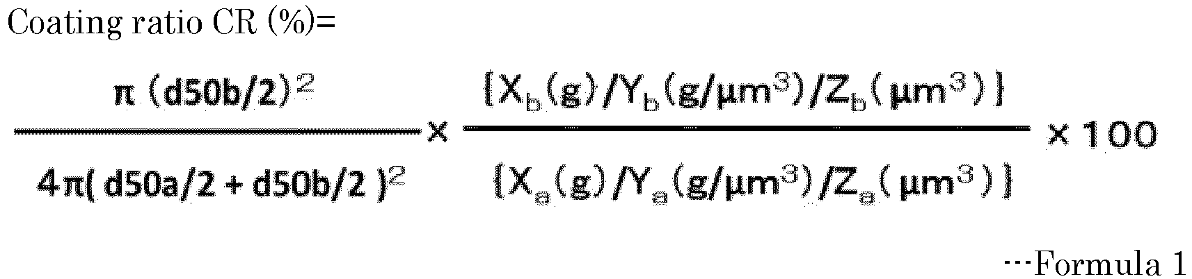
- In Formula 1, Xa represents the mass (g) of the hydrophobic solid particle A, Xb represents the mass (g) of the hydrophobic solid particle B, Ya represents the density (g/cubic micrometer) of the hydrophobic solid particle A, Yb represents the density (g/cubic micrometer) of the hydrophobic solid particle B, Za represents the volume (cubic micrometer) of the hydrophobic solid particle A, and Zb represents the volume (cubic micrometer) of the hydrophobic solid particle B.
- The surface coating unit is a unit configured to coat the surface of the liquid droplet with composite particles including a hydrophobic solid particle A and a hydrophobic solid particle B over the surface of the hydrophobic solid particle A, wherein a contact angle CAa of the hydrophobic solid particle A with water is 110 degrees or greater but 180 degrees or less, wherein a contact angle CAb of the hydrophobic solid particle B with water is 110 degrees or greater but 180 degrees or less, wherein a ratio (d50a/d50b) of the number average particle diameter d50a of the hydrophobic solid particle A to the number average particle diameter d50b of the hydrophobic solid particle B is 10 or greater but 100 or less, and wherein a coating ratio CR of the composite particles expressed by Formula 1 below is 50% or higher but 500% or lower.

- In Formula 1, Xa represents the mass (g) of the hydrophobic solid particle A, Xb represents the mass (g) of the hydrophobic solid particle B, Ya represents the density (g/cubic micrometer) of the hydrophobic solid particle A, Yb represents the density (g/cubic micrometer) of the hydrophobic solid particle B, Za represents the volume (cubic micrometer) of the hydrophobic solid particle A, and Zb represents the volume (cubic micrometer) of the hydrophobic solid particle B.
- The surface coating step is a step of coating the surface of the liquid droplet with composite particles including a hydrophobic solid particle A and a hydrophobic solid particle B over the surface of the hydrophobic solid particle A, wherein a contact angle CALa of the hydrophobic solid particle A with the solution is 100 degrees or greater but 180 degrees or less, wherein a contact angle CALb of the hydrophobic solid particle B with the solution is 100 degrees or greater but 180 degrees or less, wherein a ratio (d50a/d50b) of the number average particle diameter d50a of the hydrophobic solid particle A to the number average particle diameter d50b of the hydrophobic solid particle B is 10 or greater but 100 or less, and wherein a coating ratio CR of the composite particles expressed by Formula 1 below is 50% or higher but 500% or lower.

- In Formula 1, Xa represents the mass (g) of the hydrophobic solid particle A, Xb represents the mass (g) of the hydrophobic solid particle B, Ya represents the density (g/cubic micrometer) of the hydrophobic solid particle A, Yb represents the density (g/cubic micrometer) of the hydrophobic solid particle B, Za represents the volume (cubic micrometer) of the hydrophobic solid particle A, and Zb represents the volume (cubic micrometer) of the hydrophobic solid particle B.
- The surface coating unit is a unit configured to coat the surface of the liquid droplet with composite particles including a hydrophobic solid particle A and a hydrophobic solid particle B over the surface of the hydrophobic solid particle A, wherein a contact angle CALa of the hydrophobic solid particle A with the solution is 100 degrees or greater but 180 degrees or less, wherein a contact angle CALb of the hydrophobic solid particle B with the solution is 100 degrees or greater but 180 degrees or less, wherein a ratio (d50a/d50b) of the number average particle diameter d50a of the hydrophobic solid particle A to the number average particle diameter d50b of the hydrophobic solid particle B is 10 or greater but 100 or less, and wherein a coating ratio CR of the composite particles expressed by Formula 1 below is 50% or higher but 500% or lower.

- In Formula 1, Xa represents the mass (g) of the hydrophobic solid particle A, Xb represents the mass (g) of the hydrophobic solid particle B, Ya represents the density (g/cubic micrometer) of the hydrophobic solid particle A, Yb represents the density (g/cubic micrometer) of the hydrophobic solid particle B, Za represents the volume (cubic micrometer) of the hydrophobic solid particle A, and Zb represents the volume (cubic micrometer) of the hydrophobic solid particle B.
- The surface coating step can be suitably performed by the surface coating unit.
- In the present disclosure, "surface coating" means that the surface of a liquid droplet is coated enough to enable the effect of the present disclosure to be achieved. Surface coating is not particularly limited and may be complete coating of a liquid droplet or may be partial coating of a liquid droplet.
- The composite particles are the same as the composite particles of the present disclosure.
- The method for coating the surface of the liquid droplet is not particularly limited and may be appropriately selected depending on the intended purpose so long as the method can bring the liquid droplet and the composite particles into contact with each other. Examples of the method include a method of spraying the composite particles to the liquid droplet that is flying, and a method of locating a liquid droplet in a container in which the composite particles are densely laid. Of these methods, the method of locating a liquid droplet in a container in which the composite particles are densely laid is preferable in terms of excellent ease of device control.
- In the method of locating a liquid droplet in a container in which the composite particles are densely laid, after a liquid droplet is located in the container in which the composite particles are densely laid, it is preferable to add, for example, a step of shaking the container while supplying the composite particles into the container, and a step of inclining the container and rolling the liquid droplet, in order to coat the entire surface of the liquid droplet with the composite particles. These steps may be performed independently, or either step may be performed after the other step is performed.
- As the unit configured to supply the composite particles into the container, a commercially available powder supplying apparatus may be used. The mechanism and the type of the powder supplying apparatus may be appropriately selected depending on the conditions of the composite particles.
- The other steps are not particularly limited and may be appropriately selected depending on the intended purpose. Examples of the other steps include a separating step and a collecting step.
- The other units are not particularly limited and may be appropriately selected depending on the intended purpose. Examples of the other units include a separating unit and a collecting unit.
- The other steps can be suitably performed by the other units. The separating step can be suitably performed by the separating unit. The collecting step can be suitably performed by the collecting unit.
- The separating step is a step of separating the liquid-encapsulating particles from the composite particles left unused for surface coating in the surface coating step.
- The separating unit is a unit configured to separate the liquid-encapsulating particles from the composite particles left unused for surface coating in the surface coating step.
- Examples of the method of separating the liquid-encapsulating particles from the composite particles left unused for surface coating in the surface coating step include a method of picking up the liquid-encapsulating particles, and a method of separating the mixture of the liquid-encapsulating particles and the composite particles utilizing the density difference and removing the composite particles. Of these methods, the method utilizing the density difference is preferable in terms of productivity.
- Examples of the method of separating the mixture of the liquid-encapsulating particles and the composite particles utilizing the density difference and removing the composite particles include a method of passing the mixture through a push-pull dust chamber.
- The collecting step is a step of collecting the liquid-encapsulating particles separated.
- The collecting unit is a unit configured to collect the liquid-encapsulating particles separated.
- The method for collecting the liquid-encapsulating particles separated is not particularly limited and may be appropriately selected depending on the intended purpose. Examples of the method include a method of letting the liquid-encapsulating particles fall from the container to be collected into a collecting container. In order to alleviate the impact of falling, it is preferable to set the collecting container at a distance of within 200 mm from the container, and to incline the collecting container. It is preferable to hydrophobize the internal wall of the collecting container or to form the collecting container using a hydrophobic material.
- A biocatalyst-containing material of the present disclosure contains a liquid droplet containing a biocatalyst, and composite particles coating the surface of the liquid droplet. The number average particle diameter d50c of the biocatalyst-containing material is 10 micrometers or greater but 1,000 micrometers or less.
- Generally, substance producing processes using microorganisms that produce valuables are performed under strict management of culture fluids in large-sized culture tanks.
- However, such culture systems need appropriate stirring and supply of gases such as oxygen. This makes the process and management complicated.
- Moreover, there are cases where microorganisms that have died in the large-sized culture tanks also lead surrounding microorganisms to death. This makes substance production unsuccessful.
- According to recent reports, liquid droplets are encapsulated in particles, and biocatalysts such as microorganisms are contained in the encapsulated liquid droplets, to culture the microorganisms in the liquid-encapsulating particles (for example, see Colloids and Surfaces B: Biointerfaces 106 (2013) 187-190).
- Existing techniques for culturing, for example, microorganisms using liquid-encapsulating particles have used particles having a size of some millimeters or greater that makes durability (strength) low and coalescing likely to occur, leading to a problem that many particles cannot be handled in the same system. Another problem of the large size of the particles used is that stirring and gas supply for circulating liquids inside the particles is difficult.
- Hence, the present inventor has studied a biocatalyst-containing material having a high valuable producing efficiency and an excellent durability against external forces, and obtained the following finding.
- Existing techniques have been found to be unable to efficiently produce biocatalyst-containing liquid-encapsulating particles having a particle diameter of 10 micrometers or greater but 1,000 micrometers or less because such particles have a low durability (strength). Furthermore, although existing techniques have been able to produce particles having a particle diameter of less than 10 micrometers, it has been found that liquids tend to dry during production and adversely affect the internal biocatalysts, to make the valuable producing efficiency low. Moreover, although existing techniques have been able to produce particles having a particle diameter of greater than 2,000 micrometers, it has been found that the volume of the liquids encapsulated is so high that it is difficult to spread components (for example, oxygen) for enabling the biocatalysts to function inside the particles, to make the valuable producing efficiency low.
- The biocatalyst-containing material of the present disclosure refers to a material that is in a state that the surface of the liquid droplet is coated with the composite particles.
- In the present disclosure, "the state that the surface of the liquid droplet is coated with the composite particles" is not particularly limited so long as the surface is coated enough to enable the effect of the present disclosure to be achieved, and the surface may be completely coated or may be partially coated.
- Therefore, in order to obtain particles having an excellent valuable producing efficiency and an excellent coalescing and durability, it has been found appropriate to distribute composite particles around a liquid droplet to adjust the size of the particle to 10 micrometers or greater but 1,000 micrometers or less. The valuable is not particularly limited and may be appropriately selected depending on the intended purpose so long as the valuable ca be produced with a biocatalyst. Examples of the valuable include ethanol, acetic acid, lactic acid, butyric acid, propionic acid, and formic acid.
- The biocatalyst-containing material of the present disclosure has a high valuable producing efficiency and an excellent durability against external forces.
- The liquid droplet is not particularly limited and may be appropriately selected depending on the intended purpose so long as the liquid droplet contains a biocatalyst and is not a solution that inhibits reaction of the biocatalyst.
- The solution is not particularly limited and may be appropriately selected depending on the intended purpose so long as the solution contains water in an amount of 15% by mass or greater. Examples of the liquid include saline, a cell culture medium, and a glucose solution. Other substances that may be contained are not particularly limited and may be appropriately selected depending on the intended purpose. Examples of the substances include a water-soluble compound, and a water-insoluble compound.
- Examples of the water-soluble compound include glucose, ascorbic acid, Japanese Pharmacopoeia honey, 1-ethyl-3-methyl imidazolium trifluoromethane sulfonate ([EMIM][CF3SO3]), 1-butyl-3-methyl imidazolium trifluoromethane sulfonate ([BMIM][CF3SO3]), (1-butyl-3-methyl imidazolium=chloride ([BMIM][Cl]), glycerin, polyglycerin, and lactose.
- Examples of the water-insoluble compound include inorganic fillers such as titanium oxide, activated carbon, zeolite, and silica.
- Examples of the food additive include antioxidants such as L-sodium ascorbate, and a fungicide.
- Examples of the physiologically active substance include vitamins such as vitamin B1 and folic acid, and amino acids such as arginine and alanine.
- The biocatalyst is not particularly limited and may be appropriately selected depending on the intended purpose, so long as the biocatalyst is a living organism per se or a catalyst derived from a living organism and can change the reaction speed of a reaction of a substance transforming into a substance of a different kind.
- Examples of the living organism per se include animal cells, plant cells, and microorganisms.
- Examples of the catalyst derived from a living organism include enzymes.
- The composite particles include a hydrophobic solid particle A and a hydrophobic solid particle B, includes the hydrophobic solid particle B over the surface of the hydrophobic solid particle A, and further include other materials as needed.
- The present inventor has found that liquid droplet-encapsulating particles (may be referred to as liquid marbles or liquid-encapsulating particles) produced only with particles having a large particle diameter have a small contact area between the particles coating the liquid droplets and the liquid droplets, to have the liquid droplets exposed at some positions, leading to a very poor strength against external forces and difficulty with improving durability.
- The present inventor has also found that liquid-encapsulating particles produced only with particles having a small particle diameter have a better durability against external forces, but are easily deformable, leading to a problem that the liquid-encapsulating particles may coalesce with each other due to a capillary phenomenon.
- Hence, the present inventor has found that use of two kinds of hydrophobic solid particles having a specific property and having different particle diameters (hydrophobic solid particles A having a greater particle diameter and hydrophobic solid particles B having a smaller particle diameter) makes it possible to suppress coalescing of liquid-encapsulating particles.
- The present inventor has also found that composite particles in which the hydrophobic solid particles B are distributed over the surface of the hydrophobic solid particles A can suppress coalescing of liquid-encapsulating particles, can coat the surface of liquid droplets of various kinds of liquids, and can form liquid-encapsulating particles having an excellent durability.
- The hydrophobic solid particle B is present over the surface of the hydrophobic solid particle A and coats the surface of the hydrophobic solid particle A. The hydrophobic solid particle B coating the surface of the hydrophobic solid particle A means that the hydrophobic solid particle B coats the surface of the hydrophobic solid particle A enough to enable the effect of the present disclosure to be achieved, and that the hydrophobic solid particle B coats the surface of the hydrophobic solid particle A in a manner to satisfy a coating ratio CR described below.
- In the present disclosure, "the surface of the hydrophobic solid particle A" means the exposed surface of the hydrophobic solid particle A.
- The hydrophobic solid particle A has a contact angle CAa of 110 degrees or greater but 180 degrees or less with water. The hydrophobic solid particle B has a contact angle CAb of 110 degrees or higher but 180 degrees or lower with water.
- When the contact angles CAa and CAb with water are 110 degrees or higher but 180 degrees or lower, coalescing of the biocatalyst-containing material can be suppressed.
- In the present disclosure, "hydrophobicity" means a contact angle CAa and a contact angle CAb of 90 degrees or greater but 180 degrees or less with water when measured by a method for measuring the contact angles described below.
- With respect to a solution containing water in an amount of 15% by mass or greater, the hydrophobic solid particle A has a contact angle CALa of 100 degrees or greater but 180 degrees or lower with the solution, and the hydrophobic solid particle B has a contact angle CALb of 100 degrees or greater but 180 degrees or lower with the solution.
- When the contact angles CALa and CALb of the hydrophobic solid particle A and the hydrophobic solid particle B with the solution are 100 degrees or greater but 180 degrees or lower, coalescing of solution-encapsulating particles can be suppressed.
- As the method for measuring the contact angles CAa and CAb with water, a plate-shaped body obtained by hot-pressing the material constituting the hydrophobic solid particle A or B or a plate-shaped body obtained by casting a dispersion liquid of the material constituting the hydrophobic solid particle A or B over a substrate by a casting method is used as the sample to be measured, and the angle formed between the liquid surface of water and the surface of the plate-shaped body when the water is located in an amount of 10 microliters over the sample with a microsyringe is measured as the contact angle CAa or CAb with the water (according to a known contact angle measuring method (θ/2 method)). With the water changed to the solution, the measuring method described above can be used as the method for measuring the contact angles CALa and CALb with the solution.
- The conditions of the hot-pressing when producing the plate-shaped body by hot-pressing the material constituting the hydrophobic solid particle A or B are as follows.
-
- Temperature: 200 degrees C
- Total pressure applied: 30 kN
- Time: for 5 minutes from when the pressure reaches 30 kN
- Operation: A powder of the sample (the material constituting the hydrophobic solid particle) is filled in a powder compacting die having an internal diameter of 10 mm and a depth of 20 mm until the height of the powder from the bottom reaches 10 mm, and set in a press machine (machine name: SA302 DESK-TOP TEST PRESS, available from Tester Sangyo Co., Ltd.). After it is confirmed that the die has reached a predetermined temperature (200 degrees C), pressing is started up to a predetermined pressure (30 kN). The material is pressed for 5 minutes from when the pressure reaches the predetermined pressure. In this way, the sample is produced.
- The plate-shaped body obtained by casting a dispersion liquid of the material constituting the hydrophobic solid particle A or B over a substrate by a casting method is obtained by the hot-pressing described above on a powder of the sample (the material constituting the hydrophobic solid particle) approximately uniformly sprinkled over PTFE (polytetrafluoroethylene, with an average thickness of 200 micrometers) that is punched to have a diameter of 10 mm and set on the powder compacting die in the production of the plate-shaped body by the hot-pressing of the material constituting the hydrophobic solid particle A or B.
- The method for approximately uniformly sprinkling the powder of the sample (the material constituting the hydrophobic solid particle) is not particularly limited and may be approximately selected depending on the intended purpose. Examples of the method include a method of sprinkling a dry sample powder, and a method of sprinkling a sample dispersion liquid. A solvent used in the sample dispersion liquid is not particularly limited and may be appropriately selected depending on the intended purpose. Examples of the solvent include ethanol. When the sample dispersion liquid is used, it is easy to handle a sample having a low bulk density.
- When using the materials constituting the hydrophobic solid particle A and the hydrophobic solid particle B of the composite particles as the samples to be measured, the materials of the hydrophobic solid particle A and the hydrophobic solid particle B may be identified by, for example, gas chromatography (GC-MS), nuclear magnetic resonance (NMR), and infrared spectroscopy (IR) to procure the materials and measure the contact angles CAa and CAb with the water using the procured materials, or the hydrophobic solid particle A and the hydrophobic solid particle B may be isolated from the composite particles to produce the plate-shaped body using the hydrophobic solid particle A or hydrophobic solid particle B isolated and measure the contact angles CAa and CAb with the water. With the water changed to the solution, the measuring method described above can be used as the method for measuring the contact angles CALa and CALb with the solution.
- Examples of the method for isolating the hydrophobic solid particle A and the hydrophobic solid particle B from the composite particles include a method of filtrating a dispersion liquid of the composite particles obtained by adding an alcohol (for example, ethanol and isopropanol) to the composite particles. Of these alcohols, ethanol is preferable. Ethanol is preferable because of a high volatility that facilitates drying after filtration.
- The ratio (d50a/d50b) of the number average particle diameter d50a of the hydrophobic solid particles A to the number average particle diameter d50b of the hydrophobic solid particles B is preferably 10 or greater but 100 or less.
- The number average particle diameter d50a of the hydrophobic solid particles A and the number average particle diameter d50b of the hydrophobic solid particles B are each the average of longest diameters of ten particles arbitrarily selected from a scanning electron microscopic image of the hydrophobic solid particles A or the hydrophobic solid particles B isolated by the method described above and observed by bulk.
- The ratio (d50a/d50b) of the number average particle diameter d50a of the hydrophobic solid particles A to the number average particle diameter d50b of the hydrophobic solid particles B is preferably 10 or greater but 100 or less, and more preferably 30 or greater but 50 or less. When the ratio (d50a/d50b) of the number average particle diameter d50a of the hydrophobic solid particles A to the number average particle diameter d50b of the hydrophobic solid particles B is 10 or greater but 100 or less, a biocatalyst-containing material excellent in coalescing suppressibility and durability against external forces can be formed. When the ratio (d50a/d50b) of the number average particle diameter d50a of the hydrophobic solid particles A to the number average particle diameter d50b of the hydrophobic solid particles B is less than 10, it is difficult to form the composite particles. When the ratio (d50a/d50b) of the number average particle diameter d50a of the hydrophobic solid particles A to the number average particle diameter d50b of the hydrophobic solid particles B is greater than 100, it is possible to form the composite particles, but it is difficult to stably produce the biocatalyst-containing material.
- The number average particle diameter d50a of the hydrophobic solid particles A is not particularly limited and may be appropriately selected depending on the intended purpose so long as the effect of the present disclosure can be achieved, and is preferably 0.1 micrometers or greater but 10 micrometers or less, preferably 0.3 micrometers or greater but 5 micrometers or less, and more preferably 0.5 micrometers or greater but 1 micrometer or less. When the number average particle diameter d50a of the hydrophobic solid particles A is 0.1 micrometers or greater but 10 micrometers or less, the amount of the hydrophobic solid particles A to be adsorbed to the liquid droplets can be increased, making it possible to more stabilize the biocatalyst-containing material (liquid-encapsulating particles) to be produced.
- The number average particle diameter d50b of the hydrophobic solid particles B is not particularly limited and may be appropriately selected depending on the intended purpose so long as the effect of the present disclosure can be achieved, and for example, is preferably 0.01 micrometers or greater but 0.5 micrometers or less and more preferably 0.01 micrometers or greater but 0.05 micrometers or less. When the number average particle diameter d50b of the hydrophobic solid particles B is 0.01 micrometers or greater but 0.5 micrometers or less, the amount of the hydrophobic solid particles B to be adsorbed to the hydrophobic solid particles A can be increased, making it possible to more stabilize the biocatalyst-containing material (liquid-encapsulating particles).
- A coating ratio CR of the composite particles expressed by Formula 1 below is preferably 50% or higher but 500% or lower.

- In Formula 1, Xa represents the mass (g) of the hydrophobic solid particles A, Xb represents the mass (g) of the hydrophobic solid particles B, Ya represents the density (g/cubic micrometer) of the hydrophobic solid particles A, Yb represents the density (g/cubic micrometer) of the hydrophobic solid particles B, Za represents the volume (cubic micrometer) of the hydrophobic solid particles A, and Zb represents the volume (cubic micrometer) of the hydrophobic solid particles B.
- The mass (g) and the volume (cubic micrometer) may be values per unit particle, but may be values per bulk so long as the mass and the volume of the composite particles used can be obtained on the same basis as the values per bulk. The volume of each particle may be the average of the volumes of particles used, or may be the volume of a true sphere calculated assuming that the particle is a true sphere having an obtained number average particle diameter as the diameter.
- The coating ratio means an abundance ratio of the hydrophobic solid particle B present over the surface of the hydrophobic solid particle A.
- The coating ratio CR is obtained in the manner described below.
- When the composite particles are assumed to be true spheres (the hydrophobic solid particles A and B are also true spheres), the surface area (4π(d50a/2+d50b/2)2) of the composite particles is calculated, where (d50a/2+d50b/2), which is the sum of the quotients obtained by dividing the number average particle diameter d50a of the hydrophobic solid particles A and the number average particle diameter d50b of the hydrophobic solid particles B each by 2, is the radius of the composite particles.
- The area over which hydrophobic solid particles B coat the surface of the hydrophobic solid particle A is obtained by multiplying the area of a cross-section Sb of the hydrophobic solid particle B by the number of hydrophobic solid particles B coating one hydrophobic solid particle A, where the cross-section Sb is orthogonal to the line segment connecting the center of the one hydrophobic solid particle A with the center of the hydrophobic solid particle B and includes the center of the hydrophobic solid particle B. The area of the cross-section Sb is expressed as π(d50b/2)2, using the number average particle diameter d50b of the hydrophobic solid particles B. The number of hydrophobic solid particles B coating one hydrophobic solid particle A can be expressed as {Xb(g)/Yb(g/µm3)/Zb(g/µm3)}/{Xa(g)/Ya(g/µm3)/Za(g/µm3)}, using the mass Xa, the density Ya, and the volume Za of the hydrophobic solid particle A and the mass Xb, the density Yb, and the volume Zb of the hydrophobic solid particle B.
-
FIG. 1A is an exemplary view illustrating an example of the composite particles of the present disclosure.FIG. 1B is an exemplary view illustrating an example of a cross-section taken in the X-Z plane ofFIG. 1A . - As illustrated in
FIG. 1A , thecomposite particles 10 of the present disclosure include a hydrophobic solid particle A11 and hydrophobic solid particles B12. The hydrophobic solid particles B12 coat the surface of the hydrophobic solid particle A11. The coating ratio CR is calculated as the ratio of the area occupied by the hydrophobic solid particles B12 to the surface area of thecomposite particle 10, where the surface area of thecomposite particle 10 is calculated based on the number average particle diameter d50a of the hydrophobic solid particles A11 and the number average particle diameter d50b of the hydrophobic solid particles B12. The area occupied by the hydrophobic solid particles B12 is obtained by multiplying the area of a cross-section Sb of the hydrophobic solid particle B12 by the number of hydrophobic solid particles B coating one hydrophobic solid particle A11, where the cross-section Sb is orthogonal to the line segment connecting the center of the one hydrophobic solid particle A11 with the center of the hydrophobic solid particle B12 and includes the center of the hydrophobic solid particle B12 as illustrated inFIG 1B . - The coating ratio CR is preferably 50% or higher but 500% or lower, and more preferably 100% or higher but 200% or lower. When the coating ratio CR is 50% or higher but 500% or lower, a biocatalyst-containing material excellent in coalescing suppressibility and durability against external forces can be formed. When the coating ratio CR is lower than 50%, the hydrophobic solid particles A dominantly contact the water or the solution, making it difficult to obtain the effect of suppressing coalescing. When the coating ratio CR is higher than 500%, the hydrophobic solid particles B aggregate and accumulate over the surface of the hydrophobic solid particles A and dominantly contact the water or the solution, making it difficult to obtain the effect of suppressing coalescing.
- The material of the hydrophobic solid particles A is not particularly limited and may be appropriately selected depending on the intended purpose so long as the material has the contact angle CAa of 110 degrees or greater but 180 degrees or less with the water. Examples of the material of the hydrophobic solid particles A include organic materials and inorganic materials.
- Examples of the organic materials include polymer materials.
- Examples of the polymer materials include resins.
- Examples of the resins include fluororesins, silicone resins, cellulose, and copolymers containing at least one of these resins.
- Examples of the fluororesins include polytetrafluoroethylene (PTFE), perfluoroalkoxyalkane (PFA), perfluoroethylene propene copolymers (FEP), ethylene tetrafluoroethylene copolymers (ETFE), polyvinylidene fluoride (PVDF), polychlorotrifluoroethylene (PCTFE), and ethylene chlorotrifluoroethylene copolymers (ECTFE).
- Examples of the silicone resins include methyl silicone resins and urethane-modified silicone resins.
- Examples of the inorganic materials include silica and calcium carbonate.
- Examples of the silica include fumed silica spherical particles (QSG series: available from Shin-Etsu Chemical Co., Ltd.).
- A hydrophobizing treatment may be applied to the surfaces of the organic materials and the inorganic materials. Any of the organic materials and the inorganic materials that do not have hydrophobicity as a material property may be used with hydrophobicity imparted to the surfaces by the hydrophobizing treatment.
- Examples of the organic materials to which the hydrophobizing treatment is applied include hydrophobized starch. Examples of the hydrophobized starch include octenylsuccinic acid corn starch ester aluminum (product name: OCTIE, available from Nippon Starch Chemical Co., Ltd.).
- It is possible to confirm that the organic material is hydrophobized, by measuring the contact angle. It is possible to confirm that the organic material is hydrophobized, by measuring the contact angle of a compression-molded (e.g., hot-pressed) sample obtained by the method described above and seeing to it that the contact angle is 90 degrees or greater 180 degrees or less.
- Examples of the inorganic materials to which the hydrophobizing treatment is applied include stearic acid-treated calcium carbonate. Examples of the stearic acid-treated calcium carbonate include a product obtained by mixing calcium carbonate (100 g) with stearic acid (10 g) and methanol (500 ml), evaporating methanol at reduced pressure, and heating and drying the resultant at 50 degrees C.
- It is possible to confirm that the inorganic material is hydrophobized, by measuring the contact angle. For example, when the hydrophobizing treatment is a treatment with stearic acid, it is possible to confirm that the inorganic material is treated with stearic acid, by measuring the contact angle of a compression-molded (e.g., hot-pressed) sample and seeing to it that the contact angle is 90 degrees or greater but 180 degrees or less.
- The material of the hydrophobic solid particles B is not particularly limited and may be appropriately selected depending on the intended purpose so long as the material has the contact angle CAb of 110 degrees or greater but 180 degrees or less with the water. Examples of the material of the hydrophobic solid particles B include organic materials and inorganic materials.
- Examples of the organic materials include polymer materials.
- Examples of the polymer materials include resins.
- Examples of the resins include fluororesins, silicone resins, cellulose, and copolymers containing at least one of these resins.
- Examples of the fluororesins include polytetrafluoroethylene (PTFE), perfluoroalkoxyalkane (PFA), perfluoroethylene propene copolymers (FEP), ethylene tetrafluoroethylene copolymers (ETFE), polyvinylidene fluoride (PVDF), polychlorotrifluoroethylene (PCTFE), and ethylene chlorotrifluoroethylene copolymers (ECTFE).
- Examples of the silicone resins include methyl silicone resins and urethane-modified silicone resins.
- Examples of the inorganic materials include silica and calcium carbonate.
- Examples of the silica include fumed silica spherical particles (QSG series: available from Shin-Etsu Chemical Co., Ltd.).
- It is possible to confirm that the organic material is hydrophobized, by measuring the contact angle. It is possible to confirm that the organic material is hydrophobized, by measuring the contact angle of a compression-molded (e.g., hot-pressed) sample obtained by the method described above and seeing to it that the contact angle is 90 degrees or greater but 180 degrees or less.
- Examples of the inorganic materials to which the hydrophobizing treatment is applied include stearic acid-treated calcium carbonate. Examples of the stearic acid-treated calcium carbonate include a product obtained by mixing calcium carbonate (100 g) with stearic acid (10 g) and methanol (500 ml), evaporating methanol at reduced pressure, and heating and drying the resultant at 50 degrees C.
- It is possible to confirm that the inorganic material is hydrophobized, by measuring the contact angle. For example, when the hydrophobizing treatment is a treatment with stearic acid, it is possible to confirm that the inorganic material is treated with stearic acid, by measuring the contact angle of a compression-molded (e.g., hot-pressed) sample and seeing to it that the contact angle is 90 degrees or greater but 180 degrees or less.
- The material of the hydrophobic solid particles B may be the same as or different from the material of the hydrophobic solid particles A so long as the above-described relationship between the hydrophobic solid particles A and the hydrophobic solid particles B according to the present disclosure is satisfied. It is preferable that at least either the hydrophobic solid particle A or the hydrophobic solid particle B be formed of at least one selected from fluororesins, silica, stearic acid-treated calcium carbonate, and hydrophobized starch.
- The shape of the hydrophobic solid particles A and the hydrophobic solid particles B is not particularly limited and may be appropriately selected depending on the intended purpose so long as the shape has a structure that can achieve the effect of the present disclosure. Examples of the shape include spherical shapes, true-spherical shapes, flat shapes, acicular shapes, columnar shapes, indefinite shapes, and rectangular parallelepiped shapes.
- The structure of the hydrophobic solid particles A and the hydrophobic solid particles B is not particularly limited and may be appropriately selected depending on the intended purpose so long as the structure can achieve the effect of the present disclosure. Examples of the structure include porous structures, hollow structures, and layered structures.
- The other components are not particularly limited and may be appropriately selected depending on the intended purpose. Examples of the other components include hydrophobic solid particles other than the hydrophobic solid particles A and the hydrophobic solid particles B that constitute the composite particles, and additives.
- The hydrophobic solid particles other than the hydrophobic solid particles A and the hydrophobic solid particles B that constitute the composite particles are not particularly limited and may be appropriately selected so long as the hydrophobic solid particles are hydrophobic solid particles other than the hydrophobic solid particles A and the hydrophobic solid particles B that constitute the composite particles.
- The additives are not particularly limited and may be appropriately selected depending on the intended purpose so long as the additives can achieve the effect of the present disclosure. Examples of the additives include zinc stearate.
- The method for producing composite particles is the same as the method for producing composite particles of the present disclosure.
- The method for analyzing the conditions of the composite particles is the same as the method described in the method for producing composite particles of the present disclosure.
- The number average particle d50c of the biocatalyst-containing material is 10 micrometers or greater but 1,000 micrometers or less, preferably 15 micrometers or greater but 1,000 micrometers or less, and more preferably 500 micrometers or greater but 800 micrometers or less. When the number average particle diameter d50c of the biocatalyst-containing material is 10 micrometers or greater, the biocatalyst-containing material can be suppressed from drying during production of the liquid droplets, making it possible to efficiently produce the biocatalyst-containing material. When the number average particle diameter d50c of the biocatalyst-containing material is 1,000 micrometers or less, spontaneous coalescing of particles of the biocatalyst-containing material and explosion of the biocatalyst-containing material under the influence of the gravity can be suppressed.
- The number average particle diameter d50c of the biocatalyst-containing material is obtained by observing the biocatalyst-containing material with an optical microscope, measuring the longest diameters of arbitrary ten particles, and averaging the measured values.
- Examples of the method for analyzing the components of the liquid droplet contained in the biocatalyst-containing material (liquid-encapsulating particles) include a method of exposing the liquid-encapsulating particles to ethanol vapor, separating the liquid-encapsulating particles into the liquid (liquid droplet) and the composite particles by filtration, and analyzing the liquid. The method for analyzing the liquid is not particularly limited and may be appropriately selected depending on the intended purpose. Examples of the method include liquid chromatography.
- A biocatalyst-containing material producing method of the present disclosure includes a liquid droplet forming step of forming a liquid droplet from a liquid containing a biocatalyst, and a surface coating step of coating the surface of the liquid droplet with composite particles including a hydrophobic solid particle A and a hydrophobic solid particle B over the surface of the hydrophobic solid particle A, wherein a contact angle CAa of the hydrophobic solid particle A with water is 110 degrees or greater but 180 degrees or less, wherein a contact angle CAb of the hydrophobic solid particle B with water is 110 degrees or greater but 180 degrees or less, wherein a ratio (d50a/d50b) of the number average particle diameter d50a of the hydrophobic solid particle A to the number average particle diameter d50b of the hydrophobic solid particle B is 10 or greater but 100 or less, and wherein a coating ratio CR of the composite particles expressed by Formula 1 below is 50% or higher but 500% or lower. The biocatalyst-containing material producing method further includes other steps as needed.
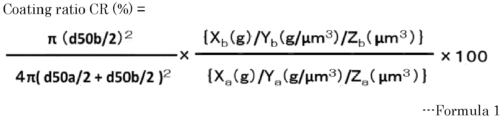
- In Formula 1, Xa represents the mass (g) of the hydrophobic solid particles A, Xb represents the mass (g) of the hydrophobic solid particles B, Ya represents the density (g/cubic micrometer) of the hydrophobic solid particles A, Yb represents the density (g/cubic micrometer) of the hydrophobic solid particles B, Za represents the volume (cubic micrometer) of the hydrophobic solid particles A, and Zb represents the volume (cubic micrometer) of the hydrophobic solid particles B.
- A biocatalyst-containing material producing apparatus of the present disclosure includes a liquid droplet forming unit configured to form a liquid droplet from a liquid containing a biocatalyst, and a surface coating unit configured to coat the surface of the liquid droplet with composite particles including a hydrophobic solid particle A and a hydrophobic solid particle B over the surface of the hydrophobic solid particle A, wherein a contact angle CAa of the hydrophobic solid particle A with water is 110 degrees or greater but 180 degrees or less, wherein a contact angle CAb of the hydrophobic solid particle B with water is 110 degrees or greater but 180 degrees or less, wherein a ratio (d50a/d50b) of the number average particle diameter d50a of the hydrophobic solid particle A to the number average particle diameter d50b of the hydrophobic solid particle B is 10 or greater but 100 or less, and wherein a coating ratio CR of the composite particles expressed by Formula 1 below is 50% or higher but 500% or lower. The biocatalyst-containing material producing apparatus further includes other units as needed.

- In Formula 1, Xa represents the mass (g) of the hydrophobic solid particles A, Xb represents the mass (g) of the hydrophobic solid particles B, Ya represents the density (g/cubic micrometer) of the hydrophobic solid particles A, Yb represents the density (g/cubic micrometer) of the hydrophobic solid particles B, Za represents the volume (cubic micrometer) of the hydrophobic solid particles A, and Zb represents the volume (cubic micrometer) of the hydrophobic solid particles B.
- A biocatalyst-containing material producing method of the present disclosure in another embodiment includes a liquid droplet forming step of forming a liquid droplet from a solution containing a biocatalyst and water in an amount of 15% by mass or greater, and a surface coating step of coating the surface of the liquid droplet with composite particles including a hydrophobic solid particle A and a hydrophobic solid particle B over the surface of the hydrophobic solid particle A, wherein a contact angle CALa of the hydrophobic solid particle A with the solution is 100 degrees or greater but 180 degrees or less, wherein a contact angle CALb of the hydrophobic solid particle B with the solution is 100 degrees or greater but 180 degrees or less, wherein a ratio (d50a/d50b) of the number average particle diameter d50a of the hydrophobic solid particle A to the number average particle diameter d50b of the hydrophobic solid particle B is 10 or greater but 100 or less, and wherein a coating ratio CR of the composite particles expressed by Formula 1 below is 50% or higher but 500% or lower. The biocatalyst-containing material producing method further includes other steps as needed.

- In Formula 1, Xa represents the mass (g) of the hydrophobic solid particles A, Xb represents the mass (g) of the hydrophobic solid particles B, Ya represents the density (g/cubic micrometer) of the hydrophobic solid particles A, Yb represents the density (g/cubic micrometer) of the hydrophobic solid particles B, Za represents the volume (cubic micrometer) of the hydrophobic solid particles A, and Zb represents the volume (cubic micrometer) of the hydrophobic solid particles B.
- A biocatalyst-containing material producing apparatus of the present disclosure in another embodiment includes a liquid droplet forming unit configured to form a liquid droplet from a solution containing a biocatalyst and water in an amount of 15% by mass or greater, and a surface coating unit configured to coat the surface of the liquid droplet with composite particles including a hydrophobic solid particle A and a hydrophobic solid particle B over the surface of the hydrophobic solid particle A, wherein a contact angle CALa of the hydrophobic solid particle A with the solution is 100 degrees or greater but 180 degrees or less, wherein a contact angle CALb of the hydrophobic solid particle B with the solution is 100 degrees or greater but 180 degrees or less, wherein a ratio (d50a/d50b) of the number average particle diameter d50a of the hydrophobic solid particle A to the number average particle diameter d50b of the hydrophobic solid particle B is 10 or greater but 100 or less, and wherein a coating ratio CR of the composite particles expressed by Formula 1 below is 50% or higher but 500% or lower. The biocatalyst-containing material producing apparatus further includes other units as needed.

- In Formula 1, Xa represents the mass (g) of the hydrophobic solid particles A, Xb represents the mass (g) of the hydrophobic solid particles B, Ya represents the density (g/cubic micrometer) of the hydrophobic solid particles A, Yb represents the density (g/cubic micrometer) of the hydrophobic solid particles B, Za represents the volume (cubic micrometer) of the hydrophobic solid particles A, and Zb represents the volume (cubic micrometer) of the hydrophobic solid particles B.
- The biocatalyst-containing material producing method of the present disclosure can be suitably performed using the biocatalyst-containing material producing apparatus. The liquid droplet forming step can be suitably performed by the liquid droplet forming unit. The surface coating step can be suitably performed by the surface coating unit.
- The liquid droplet forming step is a step of forming a liquid droplet from a liquid.
- The liquid droplet forming unit is a unit configured to form a liquid droplet from a liquid.
- The liquid droplet forming step in another embodiment is a step of forming a liquid droplet from a solution containing the biocatalyst and water in an amount of 15% by mass or greater.
- The liquid droplet forming unit in another embodiment is a unit configured to form a liquid droplet from a solution containing the biocatalyst and water in an amount of 15% by mass or greater.
- The liquid droplet forming step can be suitably performed by the liquid droplet forming unit.
- The liquid is the same as the solution used in the biocatalyst-containing material of the present disclosure.
- A known liquid droplet forming unit can be used as the liquid droplet forming unit. The liquid droplet forming unit is not particularly limited and may be appropriately selected depending on the intended purpose so long as the liquid droplet forming unit can form a liquid into a liquid droplet. Examples of the liquid droplet forming unit include an inkjet type, a dispenser type, and a spray drying type. Among these liquid droplet forming units, the dispenser type is preferable because the dispenser type is versatile with a broad range of liquid properties that can be formed into a liquid droplet and can control the size of a liquid droplet by the size of the pore diameter of the head and the pressure for pushing out the liquid filled.
- The surface coating step is a step of coating the surface of the liquid droplet with composite particles including a hydrophobic solid particle A and a hydrophobic solid particle B over the surface of the hydrophobic solid particle A, wherein a contact angle CAa of the hydrophobic solid particle A with water is 110 degrees or greater but 180 degrees or less, wherein a contact angle CAb of the hydrophobic solid particle B with water is 110 degrees or greater but 180 degrees or less, wherein a ratio (d50a/d50b) of the number average particle diameter d50a of the hydrophobic solid particle A to the number average particle diameter d50b of the hydrophobic solid particle B is 10 or greater but 100 or less, and wherein a coating ratio CR of the composite particles expressed by Formula 1 is 50% or higher but 500% or lower.

- In Formula 1, Xa represents the mass (g) of the hydrophobic solid particles A, Xb represents the mass (g) of the hydrophobic solid particles B, Ya represents the density (g/cubic micrometer) of the hydrophobic solid particles A, Yb represents the density (g/cubic micrometer) of the hydrophobic solid particles B, Za represents the volume (cubic micrometer) of the hydrophobic solid particles A, and Zb represents the volume (cubic micrometer) of the hydrophobic solid particles B.
- The surface coating unit is a unit configured to coat the surface of the liquid droplet with composite particles including a hydrophobic solid particle A and a hydrophobic solid particle B over the surface of the hydrophobic solid particle A, wherein a contact angle CAa of the hydrophobic solid particle A with water is 110 degrees or greater but 180 degrees or less, wherein a contact angle CAb of the hydrophobic solid particle B with water is 110 degrees or greater but 180 degrees or less, wherein a ratio (d50a/d50b) of the number average particle diameter d50a of the hydrophobic solid particle A to the number average particle diameter d50b of the hydrophobic solid particle B is 10 or greater but 100 or less, and wherein a coating ratio CR of the composite particles expressed by Formula 1 below is 50% or higher but 500% or lower.

- In Formula 1, Xa represents the mass (g) of the hydrophobic solid particles A, Xb represents the mass (g) of the hydrophobic solid particles B, Ya represents the density (g/cubic micrometer) of the hydrophobic solid particles A, Yb represents the density (g/cubic micrometer) of the hydrophobic solid particles B, Za represents the volume (cubic micrometer) of the hydrophobic solid particles A, and Zb represents the volume (cubic micrometer) of the hydrophobic solid particles B.
- The surface coating step can be suitably performed by the surface coating unit.
- The surface coating step in another embodiment is a step of coating the surface of the liquid droplet with composite particles including a hydrophobic solid particle A and a hydrophobic solid particle B over the surface of the hydrophobic solid particle A, wherein a contact angle CALa of the hydrophobic solid particle A with the solution is 100 degrees or greater but 180 degrees or less, wherein a contact angle CALb of the hydrophobic solid particle B with the solution is 100 degrees or greater but 180 degrees or less, wherein a ratio (d50a/d50b) of the number average particle diameter d50a of the hydrophobic solid particle A to the number average particle diameter d50b of the hydrophobic solid particle B is 10 or greater but 100 or less, and wherein a coating ratio CR of the composite particles expressed by Formula 1 is 50% or higher but 500% or lower.
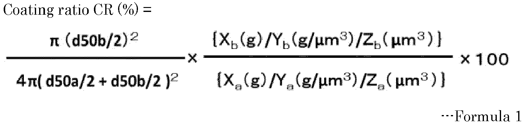
- In Formula 1, Xa represents the mass (g) of the hydrophobic solid particles A, Xb represents the mass (g) of the hydrophobic solid particles B, Ya represents the density (g/cubic micrometer) of the hydrophobic solid particles A, Yb represents the density (g/cubic micrometer) of the hydrophobic solid particles B, Za represents the volume (cubic micrometer) of the hydrophobic solid particles A, and Zb represents the volume (cubic micrometer) of the hydrophobic solid particles B.
- The surface coating unit in another embodiment is a unit configured to coat the surface of the liquid droplet with composite particles including a hydrophobic solid particle A and a hydrophobic solid particle B over the surface of the hydrophobic solid particle A, wherein a contact angle CALa of the hydrophobic solid particle A with the solution is 100 degrees or greater but 180 degrees or less, wherein a contact angle CALb of the hydrophobic solid particle B with the solution is 100 degrees or greater but 180 degrees or less, wherein a ratio (d50a/d50b) of the number average particle diameter d50a of the hydrophobic solid particle A to the number average particle diameter d50b of the hydrophobic solid particle B is 10 or greater but 100 or less, and wherein a coating ratio CR of the composite particles expressed by Formula 1 below is 50% or higher but 500% or lower.

- In Formula 1, Xa represents the mass (g) of the hydrophobic solid particles A, Xb represents the mass (g) of the hydrophobic solid particles B, Ya represents the density (g/cubic micrometer) of the hydrophobic solid particles A, Yb represents the density (g/cubic micrometer) of the hydrophobic solid particles B, Za represents the volume (cubic micrometer) of the hydrophobic solid particles A, and Zb represents the volume (cubic micrometer) of the hydrophobic solid particles B.
- In the present disclosure, "surface coating" means coating the surface of a liquid droplet. So long as the effect of the present disclosure can be achieved, "coating" may be complete coating of a liquid droplet, or may be partial coating of a liquid droplet.
- The composite particles are the same as the composite particles used in the biocatalyst-containing material of the present disclosure.
- The method for coating the surface of the liquid droplet is not particularly limited and may be appropriately selected depending on the intended purpose so long as the method can bring the liquid droplet and the composite particles into contact with each other. Examples of the method include a method of spraying the composite particles to the liquid droplet that is flying, and a method of locating a liquid droplet in a container in which the composite particles are densely laid. Of these methods, the method of locating a liquid droplet in a container in which the composite particles are densely laid is preferable in terms of excellent ease of device control.
- In the method of locating a liquid droplet in a container in which the composite particles are densely laid, after a liquid droplet is located in the container in which the composite particles are densely laid, it is preferable to add, for example, a step of shaking the container while supplying the composite particles into the container, and a step of inclining the container and rolling the liquid droplet, in order to coat the entire surface of the liquid droplet with the composite particles. These steps may be performed independently, or either step may be performed after the other step is performed.
- As the unit configured to supply the composite particles into the container, a commercially available powder supplying apparatus may be used. The mechanism and the type of the powder supplying apparatus may be appropriately selected depending on the conditions of the composite particles.
- The other steps are not particularly limited and may be appropriately selected depending on the intended purpose. Examples of the other steps include a separating step and a collecting step.
- The other units are not particularly limited and may be appropriately selected depending on the intended purpose. Examples of the other units include a separating unit and a collecting unit.
- The other steps can be suitably performed by the other units. The separating step can be suitably performed by the separating unit. The collecting step can be suitably performed by the collecting unit.
- The separating step is a step of separating the biocatalyst-containing material from the composite particles left unused for surface coating in the surface coating step.
- The separating unit is a unit configured to separate the biocatalyst-containing material from the composite particles left unused for surface coating in the surface coating step.
- Examples of the method of separating the biocatalyst-containing material from the composite particles left unused for surface coating in the surface coating step include a method of picking up particles of the biocatalyst-containing material particle by particle, and a method of separating the mixture of the biocatalyst-containing material and the composite particles utilizing the density difference and removing the composite particles. Of these methods, the method utilizing the density difference is preferable in terms of productivity.
- Examples of the method of separating the mixture of the biocatalyst-containing material and the composite particles utilizing the density difference and removing the composite particles include a method of passing the mixture through a push-pull dust chamber.
- The collecting step is a step of collecting the biocatalyst-containing material separated.
- The collecting unit is a unit configured to collect the biocatalyst-containing material separated.
- The method for collecting the biocatalyst-containing material separated is not particularly limited and may be appropriately selected depending on the intended purpose. Examples of the method include a method of letting the biocatalyst-containing material fall from the container to be collected into a collecting container. In order to alleviate the impact of falling, it is preferable to set the collecting container at a distance of within 200 mm from the container, and to incline the collecting container. It is preferable to hydrophobize the internal wall of the collecting container or to form the collecting container using a hydrophobic material.
- The present disclosure will be described below by way of Examples. The present disclosure should not be construed as being limited to these Examples.
- Polytetrafluoroethylene (PTFE, with a number average particle diameter d50a of 1.0 micrometer, a contact angle CAa of 120 degrees, a mass Xa of 10 g, a density Ya of 2.2×10⁻¹² g/cubic micrometer, and a volume Za of 0.52 cubic micrometers, obtained from Sigma-Aldrich Co., LLC., product name: 430935-100G) serving as the hydrophobic solid particles A and hydrophobic silica (with a number average particle diameter d50b of 0.03 micrometers, a contact angle CAb of 170 degrees, a mass Xb of 1.1 g, a density Yb of 1.8×10⁻¹² g/cubic micrometer, and a volume Zb of 0.14×10⁻⁴ cubic micrometers, obtained from Shin-Etsu Chemical Co., Ltd., product name: QSG30) serving as the hydrophobic solid particles B were fed to a V-type container rotary mixer (obtained from Nishimura Machine Works Co., Ltd., device name: NV-5) under an inert gas (nitrogen, 25 degrees C), and stirred at 10 rpm for 12 hours, to obtain composite particles A1. As the volume of the particles of each kind, the volume of a true sphere having the number average particle diameter, calculated assuming that the particles were a true sphere, was used.
- Next, using a syringe having a 32G syringe needle, liquid droplets were formed at the atmospheric pressure at room temperature (25 degrees C) at a rate of one droplet per second from a solution obtained by dissolving D-glucose (obtained from Tokyo Chemical Industry Co., Ltd., product name: G0048) in water to have a concentration of 20% by mass. The formed liquid droplets were located in a container (formed of PTFE) in which the composite particles A1 were densely laid, to produce liquid-encapsulating particles A1.
- Composite particles A2 to A38 and liquid-encapsulating particles A2 to A38 were produced in the same manner as in Example A1, except that unlike in Example A1, the compositions were changed to as presented in Tables A1-1 and A1-2 and Table A2.
Table A1-1 Composite particles No. Solid particle A Material d50a (micrometer) Mass Xa (g) Density Ya (g/cubic micrometer) Volume Za (cubic micrometer) Contact angle CAa (degree) Ex. A 1 1 PTFE 1.0 10.0 2.20E-12 0.52 120 2 2 PTFE 1.0 10 2.20E-12 0.52 120 3 3 PTFE 1.0 10 2.20E-12 0.52 120 4 4 PTFE 1.0 10 2.20E-12 0.52 120 5 5 PTFE 1.0 10 2.20E-12 0.52 120 6 6 PTFE 1.0 10 2.20E-12 0.52 120 7 7 PTFE 0.50 10 2.20E-12 0.07 120 8 8 PTFE 1.0 10 2.20E-12 0.52 120 9 9 Hydrophobic silica 0.30 100 1.90E-12 1.4E-02 170 10 10 Stearic acid-treated calcium carbonate 10 10 2.80E-12 524 145 11 11 Hydrophobized starch 20 100 1.70E-12 4,189 110 12 12 PTFE 1.0 10 2.20E-12 0.52 120 13 13 PTFE 1.0 100 2.20E-12 0.52 120 14 14 PTFE 0.50 10 2.20E-12 0.07 120 15 15 PTFE 1.0 10 2.20E-12 0.52 120 16 16 PTFE 1.0 10 2.20E-12 0.52 120 17 17 PTFE 1.0 10 2.20E-12 0.52 120 18 18 PTFE 1.0 10 2.20E-12 0.52 120 19 19 PTFE 1.0 10 2.20E-12 0.52 120 20 20 PTFE 1.0 10 2.20E-12 0.52 120 21 21 PTFE 1.0 10 2.20E-12 0.52 120 Table A1-2 Composite particles No. Solid particle B Material d50b (micrometer) Mass Xb (g) Density Yb (g/cubic micrometer) Volume Zb (cubic micrometer) Contact angle CAb (degree) Ex. A 1 1 Hydrophobic silica 0.03 0.52 1.80E-12 1.4E-05 170 2 2 Hydrophobic silica 0.030 0.63 1.80E-12 1.4E-05 170 3 3 Hydrophobic silica 0.030 1.06 1.80E-12 1.4E-05 170 4 4 Hydrophobic silica 0.030 2.11 1.80E-12 1.4E-05 170 5 5 Hydrophobic silica 0.030 5.28 1.80E-12 1.4E-05 170 6 6 Hydrophobic silica 0.010 0.34 1.80E-12 5.2E-07 170 7 7 Hydrophobic silica 0.010 0.69 1.80E-12 5.2E-07 170 8 8 Hydrophobized starch 0.050 1.73 1.70E-12 6.5E-05 110 9 9 Fumed silica 0.015 0.46 4.00E-14 1.8E-06 175 10 10 Hydrophobic silica 0.17 0.45 1.80E-12 2.6E-03 170 11 11 Hydrophobic silica 118 0.64 1.80E-12 1.4E-05 170 12 12 Hydrophobic silica 0.030 3.12 1.80E-12 1.4E-05 170 13 13 Fumed silica 0.015 0.12 4.00E-14 1.8E-06 175 14 14 Hydrophobized starch 0.050 3.75 1.70E-12 6.5E-05 110 15 15 Hydrophobic silica 0.030 3.12 1.80E-12 1.4E-05 170 16 16 Hydrophobic silica 0.030 3.12 1.80E-12 1.4E-05 170 17 17 Hydrophobic silica 0.030 1.06 1.80E-12 1.4E-05 170 18 18 Hydrophobic silica 0.030 1.06 1.80E-12 1.4E-05 170 19 19 Hydrophobic silica 0.030 1.06 1.80E-12 1.4E-05 170 20 20 Hydrophobic silica 0.030 1.06 1.80E-12 1.4E-05 170 21 21 Hydrophobic silica 0.030 1.06 1.80E-12 1.4E-05 170 Table A2-1 Composite particles No. Solid particle A Material d50a (micrometer) Mass Xa (g) Density Ya (g/cubic micrometer) Volume Za (cubic micrometer) Contact angle CAa (degree) Comp. Ex. A 1 22 Lactose 30 100 1.50E-12 14,137 - 2 23 PTFE 1.0 10 2.20E-12 0.52 120 3 24 Stearic acid-treated calcium carbonate 10 100 2.80E-12 524 145 4 25 PTFE 1.0 10 2.20E-12 0.52 120 5 26 Polystyrene 20 100 1.10E-12 4,189 85 6 27 Polystyrene 20 10 1.10E-12 4,189 85 7 28 PTFE 1.0 10 2.20E-12 0.52 120 8 29 PTFE 1.0 10 2.20E-12 0.52 120 9 30 Hydrophobic silica 0.30 10 1.90E-12 1.4E-02 170 10 31 - - - - - - 11 32 PTFE 1.0 10 2.20E-12 0.52 120 12 33 PTFE 1.0 10 2.20E-12 0.52 120 13 34 PTFE 1.30 10.0 2.20E-12 0.52 120 14 35 PTFE 1.00 100.0 2.20E-12 0.52 120 15 36 PTFE 1.00 10.0 2.20E-12 0.52 120 16 37 PTFE 1.0 10 2.20E-12 0.52 120 17 38 Polystyrene 1.5 100 1.10E-12 4,189 85 Table A2-2 Composite particles No. Solid particle B Material d50b (micrometer) Mass Xb (g) Density Yb (g/cubic micrometer) Volume Zb (cubic micrometer) Contact angle CAb (degree) Comp. Ex. A 1 22 Hydrophobic silica 0.030 0.48 1.80E-12 1.4E-05 170 2 23 Lactose 0.50 31.11 1.50E-12 6.5E-02 - 3 24 Hydrophobic silica 0.010 0.26 1.80E-12 5.2E-07 170 4 25 Polystyrene 1.5 190.09 1.10E-12 1.8E+00 85 5 26 Hydrophobic silica 0.030 0.98 1.80E-12 1.4E-05 170 6 27 Polystyrene 1.5 3.47 1.10E-12 1.8E+00 85 7 28 PTFE 0.50 45.00 2.20E-12 6.5E-02 120 8 29 - - - - - - 9 30 - - - - - - 10 31 Hydrophobic silica 0.030 10.00 1.80E-12 1.4E-05 170 11 32 Hydrophobic silica 0.030 0.42 1.80E-12 1.4E-05 170 12 33 Hydrophobic silica 0.030 31.68 1.80E-12 1.4E-05 170 13 34 Hydrophobic silica 0.010 0.60 1.80E-12 5.2E-07 170 14 35 Hydrophobic silica 0.170 0.42 1.80E-12 1.4E-05 170 15 36 Hydrophobic silica 0.030 5.72 1.80E-12 1.4E-05 170 16 37 Polystyrene 0.075 190.09 1.10E-12 1.8E+00 85 17 38 Hydrophobic silica 0.030 31.68 1.80E-12 1.4E-05 170 Table A3 Composite particles Particle diameter ratio d50a/d50b Coating ratio CR (%) Components other than solid particle A and solid particle B Material Content (% by mass) Ex. A 1 33 49.9 - - 2 33 60.8 - - 3 33 100 - - 4 33 200 - - 5 33 500 - - 6 100 100 - - 7 50 100 - - 8 20 100 - - 9 20 100 - - 10 59 100 - - 11 118 100 - - 12 33 299.5 - - 13 67 106.8 - - 14 10 100.3 - - 15 33 299.5 - - 16 33 299.5 - - 17 33 100 Zinc stearate 5.0 18 33 100 - - 19 33 100 - - 20 33 100 - - 21 33 100 - - Comp. Ex. A 1 1,000 100 - - 2 2 100 - - 3 1,000 100 - - 4 0.67 100 - - 5 666.7 100 - - 6 13.3 100 - - 7 2 100 - - 8 - - - - 9 - - - - 10 - - - - 11 33 40 - - 12 33 3000 - - 13 130 106.8 - - 14 6 100.3 - - 15 33 549.1 - - 16 13 100 - - 17 33 100 - - Table A4 Liquid Number average particle diameter d50c (mm) of liquid-encapsulating particle Water content (%) Second component Third component Contact angle Material Content (% by mass) Material Content (% by mass) CALa (degree) CALb (degree) Ex. A 1 80.0 D-glucose 20 - - 120 170 1.3 2 80.0 D-glucose 20 - - 120 170 1.3 3 80.0 D-glucose 20 - - 120 170 1.2 4 80.0 D-glucose 20 - - 120 170 1.3 5 80.0 D-glucose 20 - - 120 170 1.1 6 80.0 D-glucose 20 - - 120 170 1.3 7 80.0 D-glucose 20 - - 120 170 1.4 8 80.0 D-glucose 20 - - 120 170 1.3 9 80.0 D-glucose 20 - - 170 175 1.2 10 80.0 D-glucose 20 - - 145 170 1.5 11 80.0 D-glucose 20 - - - 170 1.8 12 80.0 D-glucose 20 - - 120 170 1.1 13 80.0 D-glucose 20 - - 120 170 1.1 14 80.0 D-glucose 20 - - 120 170 1.1 15 80.0 D-glucose 20 - - 120 170 0.015 16 80.0 D-glucose 20 - - 120 170 2.5 17 80.0 D-glucose 20 - - 120 170 1.5 18 15.0 D-glucose 40 Official honey 45 100 160 1.4 19 60.0 D-glucose 20 Official honey 20 105 165 1.5 20 79.5 D-glucose 20 Ascorbic acid 0.5 110 165 1.6 21 100 - - - - - - 1.2 Comp. Ex. A 1 80.0 D-glucose 20 - - 120 170 - 2 80.0 D-glucose 20 - - 120 170 1.9 3 80.0 D-glucose 20 - - 140 170 1.3 4 80.0 D-glucose 20 - - 140 170 1.5 5 80.0 D-glucose 20 - - 140 170 1.4 6 80.0 D-glucose 20 - - 80 80 - 7 80.0 D-glucose 20 - - 140 170 1.3 8 80.0 D-glucose 20 - - 120 170 1.4 9 80.0 D-glucose 20 - - 120 170 1.7 10 100 - - - - - - 1.4 11 80.0 D-glucose 20 - - 120 170 1.5 12 80.0 D-glucose 20 - - 120 170 1.1 13 80.0 D-glucose 20 - - 120 170 1.4 14 80.0 D-glucose 20 - - 120 170 1.4 15 80.0 D-glucose 20 - - 120 170 1.4 16 80.0 D-glucose 20 - - 120 80 1.1 17 80.0 D-glucose 20 - - 80 170 1.1 - The details of the materials used in Examples and Comparative Examples are as follows.
-
- Polytetrafluoroethylene (PTFE, with a number average particle diameter d50a of 1.3 micrometers, 1.0 micrometer, and 0.50 micrometers, a contact angle CAa of 120 degrees, and a density Ya of 2.2×10⁻¹² g/cubic micrometer, obtained from Sigma-Aldrich Co., LLC., product name: 430935-100G)
- Hydrophobic silica (with a number average particle diameter d50a of 0.30 micrometers, a contact angle CAa of 170 degrees, and a density Ya of 1.9×10⁻¹² g/cubic micrometer, obtained from Nippon Shokubai Co. Ltd., product name: E30) immersed in hexamethylene disilazane (obtained from Tokyo Chemical Industry Co., Ltd.), filtrated, and heated at 120 degrees C
- Stearic acid-treated calcium carbonate (with a number average particle diameter d50a of 10 micrometers, a contact angle CAa of 145 degrees, and a density Ya of 2.8×10⁻¹² g/cubic micrometer), obtained by mixing calcium carbonate (obtained from Tokyo Chemical Industry Co., Ltd.) (100 g) with stearic acid (obtained from Tokyo Chemical Industry Co., Ltd.) (10 g) and methanol (obtained from Tokyo Chemical Industry Co., Ltd.) (500 ml) and subsequently evaporating methanol at reduced pressure and heating the resultant at 50 degrees C for drying.
- Hydrophobized starch (with a number average particle diameter d50a of 20 micrometers, a contact angle CAa of 110 degrees, and a density Ya of 1.7×10⁻¹² g/cubic micrometer, obtained from Nippon Starch Chemical Co., Ltd., product name: OCTIE)
-
- Lactose (with a number average particle diameter d50a of 30 micrometers, a contact angle CAa of 0 degrees when dissolved, and a density Ya of 1.5×10⁻¹² g/cubic micrometer, obtained from Yoneyama Yakuhin Kogyo Co., Ltd., product name: LACTOSE)
- Polystyrene (with a number average particle diameter d50a of 20 micrometers, a contact angle CAa of 85 degrees, and a density Ya of 1.1×10⁻¹² g/cubic micrometer, obtained from Sigma-Aldrich Co., LLC., product name: POLYSTYRENE MICROPARTICLES 84135-5ML-F)
-
- Hydrophobic silica (with a number average particle diameter d50b of 0.17 micrometers, 0.030 micrometers, and 0.010 micrometers, a contact angle CAb of 170 degrees, and a density Yb of 1.8×10⁻¹² g/cubic micrometer, obtained from Shin-Etsu Chemical Co., Ltd., product name: QSG170, QSG30, and QSG10)
- Hydrophobized starch (with a number average particle diameter d50b of 0.050 micrometers, a contact angle CAb of 110 degrees, and a density Yb of 1.7×10⁻¹² g/cubic micrometer, obtained from Nippon Starch Chemical Co., Ltd., product name: OCTIE)
- Polytetrafluoroethylene (PTFE, with a number average particle diameter d50b of 1.0 micrometer and 0.50 micrometers, a contact angle CAb of 120 degrees, and a density Yb of 2.2×10⁻¹² g/cubic micrometer, obtained from Sigma-Aldrich Co., LLC., product name: 430935-100G)
- Fumed silica (with a number average particle diameter d50b of 0.015 micrometers, a contact angle CAb of 175 degrees, and a density Yb of 4.0×10⁻¹⁴ g/cubic micrometer, obtained from Wacker Chemicals Co., Ltd., product name: HDK-H18)
- Polystyrene (with a number average particle diameter d50b of 1.5 micrometers, a contact angle CAb of 85 degrees, and a density Yb of 1.1×10⁻¹² g/cubic micrometer, obtained from Sigma-Aldrich Co., LLC., product name: POLYSTYRENE MICROPARTICLES 79166-5ML-F)
- Polystyrene (with a number average particle diameter d50b of 0.075 micrometers, a contact angle CAb of 85 degrees, and a density Yb of 1.1×10⁻¹² g/cubic micrometer, obtained from Creative Diagnostics Inc., Product name: DIAGPOLY™ PLAIN POLYSTYRENE PARTICLES, from 0.05 micrometers through 0.1 micrometers)
-
- Lactose (with a number average particle diameter d50b of 0.50 micrometers, a contact angle CAb of 0 degrees when dissolved, and a density Yb of 1.5×10⁻¹² g/cubic micrometer, obtained from Yoneyama Yakuhin Kogyo Co., Ltd.)
-
- D-glucose (obtained from Tokyo Chemical Industry Co., Ltd.)
- Official honey (obtained from Nakakita Co., Ltd.)
- Ascorbic acid (obtained from Tokyo Chemical Industry Co., Ltd.)
-
- Zinc stearate (with a number average particle diameter d50b of 15 micrometers, a contact angle CAb of 85 degrees, and a density of 1.1×10⁻¹² g/cubic micrometer, obtained from Yoneyama Yakuhin Kogyo Co., Ltd.)
- Next, "coalescing suppressibility" and "durability" of the liquid-encapsulating particles A1 to A38 obtained in Examples A1 to A21 and Comparative Examples A1 to A17 were measured and evaluated in the manners described below. The results are presented in Table A5.
- A glass petri dish having a diameter of 30 mm was washed with a neutral detergent, then immersed in a saturated sodium hydroxide aqueous solution for 8 hours or longer, and then rinsed and washed with pure water. After dried sufficiently, the glass petri dish was left to stand still for 12 hours in a tightly closed container filled with hexamethylene disilazane vapor. The resultant glass petri dish was used as a glass petri dish for evaluation 1.
- The composite particles were added in the glass petri dish for evaluation 1 in a manner that the composite particles would have a thickness of about 2 mm from the bottom surface. While the resultant glass petri dish for evaluation 1 was gyratorily shaken at 20 rpm with a gyratory shaker (obtained from Corning Inc.), a liquid were dropped in 10 microliters with a microsyringe. One minute later, the liquid was dropped in another 10 microliters. When two liquid-encapsulating particles coalesced into one particle through another one minute of gyratory shaking, the rating of the evaluation was E. When no two liquid-encapsulating particles coalesced, evaluation 2 was performed.
- The composite particles were added in a PTFE-made container having a diameter of 72 mm and a height of 89 mmH in a manner that the composite particles would have a thickness of about 50 mm from the bottom surface, and the resultant container was gyratorily shaken at 200 rpm with a gyratory shaker (obtained from Corning Inc.). With a dispenser (obtained from Musashi Engineering, Inc.), liquid droplets (of the liquid having the composition described in Table A4) having a diameter of 1 mm were discharged into the container at a rate of one droplet per second.
- After 1,000 droplets were discharged, the inside of the container was visually observed. When any liquid-encapsulating particles had coalesced and exploded to form a film of the composite particles over the water surface, the rating of the evaluation was D. When no film of the composite particles had formed over the water surface, more liquid droplets were discharged.
- After a total of 2,000 droplets were discharged, the inside of the container was visually observed. When any liquid-encapsulating particles had coalesced and exploded to form a film of the composite particles over the water surface, the rating of the evaluation was C. When no film of the composite particles had formed over the water surface, more liquid droplets were discharged.
- After a total of 3,000 droplets were discharged, the inside of the container was visually observed. When any liquid-encapsulating particles had coalesced and exploded to form a film of the composite particles over the water surface, the rating of the evaluation was B. When no film of the composite particles had formed over the water surface, the rating of the evaluation was A.
- Scores were calculated according to the evaluation criteria described below.
-
- A: 10 points
- B: 8 points
- C: 6 points
- D: 4 points
- E: 0 points
- A 1 mL vial was filled with the produced liquid-encapsulating particles (500 mg) and capped. The resultant was used as a measurement sample. The measurement sample was let to freely fall onto a wood block from a height of 200 mm, and the inside of the vial was visually observed. This operation was repeated until all of the liquid-encapsulating particles exploded and no longer had the particle shape. The number of times of this operation when all of the liquid-encapsulating particles exploded was obtained as a measurement, and scores were calculated according to the evaluation criteria described below.
-
- Six times or more: 10 points
- Five times: 8 points
- Four times: 6 points
- Three times: 4 points
- Two times: 2 points
- One time or less: 0 points
- The total of the scores of "coalescing suppressibility" and "durability" was evaluated according to the evaluation criteria described below. A product that scored 0 points in any of the evaluations was given the worst rating "Failure". Products with the ratings "E" and "Failure" are not industrially applicable.
-
- A: Higher than 18 points but 20 points or lower
- B: Higher than 16 points but 18 points or lower
- C: Higher than 12 points but 16 points or lower
- D: Higher than 8 points but 12 points or lower
- E: 8 points or lower
-
FIG. 2A illustrates an electron microscopic image of the composite particles A21 used in Example A21.FIG. 2B illustrates an electron microscopic image of the hydrophobic solid particles A used in Example A21.FIG. 2C illustrates an electron microscopic image of the hydrophobic solid particles B used in Example A21 and Comparative Example A10.FIG. 3A illustrates an image of the liquid-encapsulating particles of Example A21.FIG. 3B illustrates an image of the liquid-encapsulating particles of Comparative Example A10. - It was possible to observe a state that the surface of PTFE, which served as the hydrophobic solid particles A illustrated in
FIG. 2B , was coated with hydrophobic silica, which served as the hydrophobic solid particles B illustrated inFIG. 2C , at a coating ratio of 100% as illustrated inFIG. 2A . - The liquid-encapsulating particles obtained using the composite particles illustrated in
FIG. 2A had a ratio (longer axis/shorter axis) of 1.34/1.31=1.02 between the length of the longer axis and the length of the shorter axis. As compared, the liquid-encapsulating particles obtained using only hydrophobic silica serving as the hydrophobic solid particles B had a ratio (longer axis/shorter axis) of 1.43/1.31=1.09 between the length of the longer axis and the length of the shorter axis. - Polytetrafluoroethylene (PTFE, with a number average particle diameter d50a of 1.0 micrometer, a contact angle CAa of 120 degrees, a mass Xa of 10 g, a density Ya of 2.2×10⁻¹² g/cubic micrometer, and a volume Za of 0.52 cubic micrometers, obtained from Sigma-Aldrich Co., LLC., product name: 430935-100G) serving as the hydrophobic solid particles A and hydrophobic silica (with a number average particle diameter d50b of 0.030 micrometers, a contact angle CAb of 170 degrees, a mass Xb of 1.1 g, a density Yb of 1.8×10⁻¹² g/cubic micrometer, and a volume Zb of 1.4×10⁻⁵ cubic micrometers, obtained from Shin-Etsu Chemical Co., Ltd., product name: QSG30) serving as the hydrophobic solid particles B were fed to a V-type container rotary mixer (obtained from Nishimura Machine Works Co., Ltd., device name: NV-5) under an inert gas (nitrogen, 25 degrees C), and stirred at 10 rpm for 12 hours, to obtain composite particles B1. As the volume of the particles of each kind, the volume of a true sphere having the number average particle diameter, calculated assuming that the particles were a true sphere, was used.
- Next, a solution obtained by dissolving a yeast fungus (scientific name: Saccharomyces Cerevisiae, obtained from Nisshin Seifun Group Inc., product name: DRY YEAST), and D-glucose (obtained from Tokyo Chemical Industry Co., Ltd.) (20% by mass) in water was formed into liquid droplets using a syringe having a 32G syringe needle under the atmosphere at room temperature at a dropping speed of one droplet per second, to locate the formed liquid droplets in a container (formed of PTFE) in which the composite particles B1 were densely laid, to produce a sample B1.
- Samples B2 to B30 were produced in the same manner as in Example B1, except that unlike in Example B1, the composition was changed to as presented in Table B1-1 to Table B6-2. In Comparative Example 3, the solution having the composition presented in Table B1-1 to Table B6-2 was prepared in 100 mL and used for the evaluation described below.
Table B1-1 Composite particles Solid particle A Material d50a (micrometer) Mass Xa (g) Density Ya (g/cubic micromete r) Volume Za (cubic micromete r) Contact angle CAa (degree) Ex. B 1 PTFE 1.0 10.0 2.20E-12 0.524 120 2 PTFE 1.0 10.0 2.20E-12 0.524 120 3 PTFE 1.0 10.0 2.20E-12 0.524 120 4 PTFE 1.0 10.0 2.20E-12 0.524 120 5 PTFE 1.0 10.0 2.20E-12 0.524 120 6 PTFE 0.50 10.0 2.20E-12 6.54E-02 120 7 PTFE 1.0 10.0 2.20E-12 0.524 120 Comp. Ex. B 1 PTFE 1.0 10.0 2.20E-12 0.524 120 2 PTFE 1.0 10.0 2.20E-12 0.524 120 Table B1-2 Composite particles Solid particle B Material d50b (micrometer) Mass Xb (g) Density Yb (g/cubic micrometer) Volume Zb (cubic micrometer) Contact angle CAb (degree) Ex. B 1 Hydrophobic silica 0.030 0.63 1.80E-12 1.41E-05 170 2 Hydrophobic silica 0.030 1.06 1.80E-12 1.41E-05 170 3 Hydrophobic silica 0.030 5.28 1.80E-12 1.41E-05 170 4 Hydrophobic silica 0.030 1.06 1.80E-12 1.41E-05 170 5 Hydrophobic silica 0.010 0.34 1.80E-12 5.24E-07 170 6 Hydrophobic silica 0.010 0.69 1.80E-12 5.24E-07 170 7 Hydrophobic silica 0.030 1.06 1.80E-12 1.41E-05 170 Comp. Ex. B 1 Hydrophobic silica 0.030 1.06 1.80E-12 1.41E-05 170 2 Hydrophobic silica 0.030 1.06 1.80E-12 1.41E-05 170 Table B2-1 Composite particles Solid particle A Material d50a (micrometer) Mass Xa (g) Density Ya (g/cubic micrometer) Volume Za (cubic micrometer) Contact angle CAa (degree) Ex. B 8 PTFE 1.0 10.0 2.20E-12 0.524 120 9 PTFE 1.0 10.0 2.20E-12 0.524 120 10 PTFE 1.0 10.0 2.20E-12 0.524 120 11 PTFE 1.0 10.0 2.20E-12 0.524 120 12 Hydrophobic silica 0.30 100.0 1.90E-12 1.41E-02 170 13 PTFE 1.30 10.0 2.20E-12 0.524 120 14 PTFE 1.0 10.0 2.20E-12 0.524 120 15 PTFE 0.50 10.0 2.20E-12 6.54E-02 120 16 PTFE 1.0 100.0 2.20E-12 0.524 120 17 PTFE 1.0 10.0 2.20E-12 0.524 120 18 PTFE 1.0 10.0 2.20E-12 0.524 120 19 PTFE 1.0 10.0 2.20E-12 0.524 120 20 PFA AGC Inc. ACX-34 5.0 10.0 2.20E-12 65.4 105 21 PTFE 1.0 10.0 2.20E-12 0.524 120 22 PFA AGC Inc. ACX-34 5.0 10.0 2.20E-12 65.4 105 23 Hydrophobic silica 0.30 10.0 1.80E-12 1.41E-02 170 24 Hydrophobic silica 1.0 10.0 2.10E-12 0.524 60.0 Comp. Ex. B 3 PTFE 1.0 10.0 2.20E-12 0.524 120 4 - - - - - - 5 PTFE 1.0 10.0 2.20E-12 0.524 120 6 - - - - - - Table B2-2 Composite particles Solid particle B Material d50b (micrometer) Mass Xb (g) Density Yb (g/cubic micrometer) Volume Zb (cubic micrometer) Contact angle CAb (degree) Ex. B 8 Hydrophobic silica 0.030 0.47 1.80E-12 1.41E-05 170 9 Hydrophobic silica 0.030 2.12 1.80E-12 1.41E-05 170 10 Hydrophobic silica 0.030 2.12 1.80E-12 1.41E-05 170 11 Hydrophobic silica 0.030 6.25 1.80E-12 1.41E-05 170 12 Fumed silica 0.015 0.46 4.00E-14 1.77E-06 175 13 Hydrophobic silica 0.010 0.60 1.80E-12 5.24E-07 170 14 Hydrophobic silica 0.010 0.34 1.80E-12 5.24E-07 170 15 Hydrophobic silica 0.010 0.69 1.80E-12 5.24E-07 170 16 Hydrophobic silica 0.17 0.42 1.80E-12 1.41E-05 170 17 Hydrophobic silica 0.030 1.06 1.80E-12 1.41E-05 170 18 Hydrophobic silica 0.030 1.06 1.80E-12 1.41E-05 170 19 Hydrophobic silica 0.030 1.06 1.80E-12 1.41E-05 170 20 Hydrophobic silica 0.17 1.22 1.80E-12 2.57E-03 170 21 Titanium oxide TTO"55(c) 0.10 9.31 4.23E-12 5.24E-04 105 22 Titanium oxide TTO-55(c) 0.050 0.79 4.23E-12 6.54E-05 105 23 Hydrophobic silica 0.030 4.84 1.80E-12 1.41E-05 170 24 Hydrophobic silica 0.030 1.10 1.80E-12 1.41E-05 170 Comp. Ex. B 3 Hydrophobic silica 0.030 1.06- 1.80E-12 1.41E-05 170 4 - - - - - - 5 - - - - - 6 Hydrophobic silica 0.030 1.06 1.80E-12 1.41E-05 170 Table B3 Composite particles Particle diameter ratio (d50a/d50b) Coating ratio CR (%) Ex. B 1 33 60 2 33 100 3 33 500 4 33 100 5 100 100 6 50 100 7 33 100 Comp. Ex. B 1 33 100 2 33 100 Table B4 Composite particles Particle diameter ratio (d50a/d50b) Coating ratio CR (%) Ex. B 8 33 45 9 33 100 10 33 200 11 33 600 12 20 100 13 130 100 14 100 100 15 50 100 16 6 100 17 33 100 18 33 100 19 33 100 20 29 100 21 10 100 22 100 100 23 10 100 24 33 100 Comp. Ex. B 3 33 100 4 - - 5 - - 6 - - Table B5 Solution containing biocatalyst Biocatalyst-containing material Biocatalyst Water Matrix Other components Contact angle CALa (degree) Contact angle CALb (degree) Number average particle diameter d50c (micrometer) Kind Content (% by mass) Content (% by mass) Material Content (% by mass) Material Content (% by mass) Ex. B 1 Yeast fungus 0.1 79.4 D glucose 20 Glycerin 0.5 150 160 600 2 Yeast fungus 0.5 79.0 D glucose 20 Glycerin 0.5 140 150 500 3 Yeast fungus 1.0 78.5 D glucose 20 Glycerin 0.5 120 130 900 4 Yeast fungus 0.5 79.0 D glucose 20 Glycerin 0.5 140 150 800 5 Yeast fungus 0.5 79.0 Official honey 20 Glycerin 0.5 110 120 800 6 Yeast fungus 0.5 19.5 Official honey 40 Glycerin 40.0 105 115 800 7 Yeast fungus 0.5 79.0 D glucose 20 - - 140 150 500 Comp. Ex. B 1 Yeast fungus 0.5 79.0 D glucose 20 Glycerin 0.5 110 160 5 2 Yeast fungus 0.5 79.0 D glucose 20 Glycerin 0.5 110 160 1,600 Table B6-1 Solution containing biocatalyst Biocatalyst-containing material Biocatalyst Water Matrix Other components Contact angle CALa (degree) Contact angle CALb (degree) Number average particle diameter d50c (micrometer) Kind Content (% by mass) Content (% by mass) Material Content (% by mass) Material Content (% by mass) 8 Yeast fungus 0.5 79.0 D glucose 20 Glycerin 0.5 140 150 500 9 Yeast fungus 0.5 79.0 D glucose 20 Glycerin 0.5 140 150 200 10 Yeast fungus 0.5 79.0 D glucose 20 Glycerin 0.5 140 150 200 11 Yeast fungus 0.5 79.0 D glucose 20 Glycerin 0.5 140 150 200 12 Yeast fungus 0.5 79.0 D glucose 20 Glycerin 0.5 140 150 200 13 Yeast fungus 0.5 79.0 D glucose 20 Glycerin 0.5 140 150 200 14 Yeast fungus 0.5 79.0 D glucose 20 Glycerin 0.5 140 150 200 15 Yeast fungus 0.5 79.0 D glucose 20 Glycerin 0.5 140 150 200 Ex. B 16 Yeast fungus 0.5 79.0 D glucose 20 Glycerin 0.5 140 150 200 17 Yeast fungus 0.5 79.0 D glucose 20 Glycerin 0.5 140 150 10 18 Yeast fungus 0.5 79.0 D glucose 20 Glycerin 0.5 140 150 100 19 Yeast fungus 0.5 79.0 D glucose 20 Glycerin 0.5 140 150 1,000 20 Yeast fungus 0.5 79.0 D glucose 20 Glycerin 0.5 100 160 600 21 Yeast fungus 0.5 79.0 D glucose 20 Glycerin 0.5 110 100 500 22 Yeast fungus 0.5 79.0 D glucose 20 Glycerin 0.5 95 100 500 23 Yeast fungus 0.1 79.0 D glucose 20 Glycerin 0.5 175 175 600 24 Yeast fungus 0.5 79.0 D glucose 20 Glycerin 0.5 90 160 500 Table B6-2 Solution containing biocatalyst Biocatalyst-containing material Biocatalyst Water Matrix Other components Contact angle CALa (degree) Contact angle CALb (degree) Number average particle diameter d50c (micrometer) Kind Content (% by mass) Content (% by mass) Material Content (% by mass) Material Content (% by mass) Comp. Ex. B 3 Yeast fungus 0.5 79.0 D glucose 20 Glycerin 0.5 110 160 1,100 4 Yeast fungus 0.5 79.0 D glucose 20 Glycerin 0.5 - - - 5 Yeast fungus 0.5 79.0 D glucose 20 Glycerin 0.5 110 - 500 6 Yeast fungus 0.5 79.0 D glucose 20 Glycerin 0.5 - 160 500 - The details of the materials used in Examples and Comparative Examples are as follows.
-
- Polytetrafluoroethylene (PTFE, with a number average particle diameter d50a of 1.0 micrometer and 0.50 micrometers, a contact angle CAa of 120 degrees, and a density Ya of 2.2×10⁻¹² g/cubic micrometer, obtained from Sigma-Aldrich Co., LLC., product name: 430935-100G)
- Hydrophobic silica (with a number average particle diameter d50a of 0.30 micrometers, a contact angle CAa of 170 degrees, and a density Ya of 1.9×10⁻¹² g/cubic micrometer, obtained from Nippon Shokubai Co. Ltd., product name: E30) immersed in hexamethylene disilazane (obtained from Tokyo Chemical Industry Co., Ltd.), filtrated, and heated at 120 degrees C
- Hydrophilic silica (with a number average particle diameter d50a of 1.0 micrometer, a contact angle CAa of 60 degrees, and a density Ya of 2.2×10⁻¹² g/cubic micrometer, obtained from Corefront Corporation, product name: MICROMOD)
- Perfluoroalkoxyalkane (PFA, with a number average particle diameter d50a of 5.0 micrometers, a contact angle CAa of 105 degrees, and a density Ya of 2.2×10⁻¹² g/cubic micrometer, obtained from AGC Inc., product name: ACX-34
-
- Hydrophobic silica (with a number average particle diameter d50b of 0.17 micrometers, 0.030 micrometers, and 0.010 micrometers, a contact angle CAb of 170 degrees, and a density Yb of 1.8×10⁻¹² g/cubic micrometer, obtained from Shin-Etsu Chemical Co., Ltd., product name: QSG170, QSG30, and QSG10)
- Titanium oxide (with a number average particle diameter d50a of 0.10 micrometers and 0.050 micrometers, a contact angle CAa of 105 degrees, and a density Yb of 2.2×10⁻¹² g/cubic micrometers, obtained from Ishihara Sangyo Kaisha, Ltd., product name: TTO-55(C))
-
- Yeast fungus (scientific name: Saccharomyces Cerevisiae, obtained from Nisshin Seifun Group Inc., product name: DRY YEAST)
-
- D-glucose (obtained from Tokyo Chemical Industry Co., Ltd.)
- Official honey (obtained from Nakakita Co., Ltd.)
-
- Glycerin (obtained from FUJIFILM Wako Pure Chemical Corporation)
- Next, "valuable producing efficiency ([evaluation of valuable production] and [evaluation of matrix consumption])" and "durability" of the samples B1 to B7, and B25 and B26 obtained in Examples B1 to B7 and Comparative Examples B1 and B2 were measured and evaluated in the manners described below. The results are presented in Tables 7 and 8. For the samples B8 to B24 and B27 to B30 obtained in Examples B8 to B24 and Comparative Examples B3 to B6, the results of only [evaluation of matrix consumption] are presented in terms of "valuable producing efficiency"
- Valuable producing efficiency of the biocatalyst (yeast fungus) was evaluated by conducting "evaluation of valuable production" and "evaluation of matrix consumption".
- The produced sample (10 g) was filled in a 200 mL airtight container (product name: GL45 SERIES, obtained from Sibata Scientific Technology Ltd.), and left to stand still at 35 degrees C in a nitrogen atmosphere for 12 hours. After the leaving to stand still, the container was immersed in a hot-water bath at 70 degrees C and further left to stand still for 2 hours. Subsequently, a gas (100 mL) was collected from the container and the content ratio of ethanol in the gas was measured. For obtaining the content ratio of ethanol, a Kitagawa gas sampler (AP-20) and an ethanol detection tube (ETHANOL 12) obtained from Gastec Corporation were used. The measured value obtained was used as a production rate A (%).
- As a control test, a liquid containing a biocatalyst in the same amount as used for producing the above-described sample (10 g) was filled in the same container, and subsequently left to stand still under the same conditions. A gas was collected in the same manner to measure the content ratio of ethanol. The measured value obtained was used as a production rate B (%).
- The difference between the production rate A and the production rate B was defined by the formula below, and evaluated according to the evaluation criteria.

-
- 10 points: C was 0.05 or greater.
- 8 points: C was 0.01 or greater but less than 0.01.
- 5 points: C was greater than 0 but less than 0.01.
- 0 points: C was 0 or less.
- The produced sample (10 g) was filled in a 100 mL airtight container (product name: GL45 SERIES, obtained from Sibata Scientific Technology Ltd.), and left to stand still at 35 degrees C in a nitrogen atmosphere for 12 hours. Subsequently, the liquid component was extracted from the gas phase and the sample in the container, the concentration of the liquid component was measured using a refractometer, and subsequently the amount of the matrix component in the container was measured. The liquid component was extracted by exposing the sample to ethanol vapor and separating the sample into the composite particles and liquid droplets (liquid) by filtration through a 200 micrometer filter.
- A matrix consumption ratio A between before and after the reaction was calculated according to the formula below including an amount of supply of the matrix.

- As a control test, the reaction was performed in the same manner as described above, except that a liquid containing a biocatalyst in the same amount as used for producing the above-described sample (10 g) was filled in the same container and allowed to undergo a substance producing reaction with flow supply of the matrix under the same condition, at the same temperature, atmosphere, and time conditions, and a matrix consumption ratio B between before and after the reaction was calculated according to the formula below including an amount of supply of the matrix.

- The difference between the matrix consumption ratio A and the matrix consumption ratio B was defined by the formula below, and evaluated according to the evaluation criteria.

-
- 10 points: C was 20 or greater.
- 8 points: C was 10 or greater but less than 20.
- 5 points: C was greater than 0 but less than 10.
- 0 points: C was 0 or less.
- A 1 mL vial was filled with the produced sample (500 mg) and capped to be used as a measurement sample. The measurement sample was let to freely fall onto a wood block from a height of 200 mm, and the inside of the measurement sample was observed. This operation was repeated until all particles of the sample exploded and no longer had the particle shape. The number of times of this operation when all particles of the sample exploded was obtained as a measurement, and the score was calculated according to the evaluation criterial described below.
-
- 6 times or more: 10 points
- 5 times: 8 points
- 4 times: 6 points
- 3 times: 4 points
- 2 times: 2 points
- 1 time or less: 0 points
- The total of the scores of "valuable producing efficiency" and "durability" was evaluated according to the evaluation criteria described below. Any sample that scored 0 points in any of the evaluations was given the worst rating "Failure". Samples with the ratings "D", "E", and "Failure" are not industrially applicable.
-
- A: 27 points or higher but 30 points or lower
- B: 24 points or higher but 26 points or lower
- C: 21 points or higher but 23 points or lower
- D: 18 points or higher but 20 points or lower
- E: 17 points or lower
-
- A: 17 points or higher but 20 points or lower
- B: 14 points or higher but 16 points or lower
- C: 11 points or higher but 13 points or lower
- D: 8 points or higher but 10 points or lower
- E: 7 points or lower
-
FIG. 2A illustrates an electron microscopic image of the composite particles used in Example B2.FIG. 2B illustrates an electron microscopic image of the hydrophobic solid particles A used in Example B2.FIG. 2C illustrates an electron microscopic image of the hydrophobic solid particles B used in Example B2.FIG. 3A illustrates an image of the sample (biocatalyst-containing material) of Example B2.FIG. 3B illustrates an image of the sample (biocatalyst-containing material) of Comparative Example B6. - It was possible to observe a state that the surface of PTFE, which served as the hydrophobic solid particles A illustrated in
FIG. 2B , was coated with hydrophobic silica, which served as the hydrophobic solid particles B illustrated inFIG. 2C , at a coating ratio of 100% as illustrated inFIG. 2A . - The sample (biocatalyst-containing material) obtained using the composite particles illustrated in
FIG. 2A had a ratio (longer axis/shorter axis) of 1.34/1.31=1.02 between the length of the longer axis and the length of the shorter axis. As compared, a sample (biocatalyst-containing material) obtained using only hydrophobic silica serving as the hydrophobic solid particles B had a ratio (longer axis/shorter axis) of 1.43/1.31=1.09 between the length of the longer axis and the length of the shorter axis. - Aspects of the present disclosure are, for example, as follows.
- <A1> Composite particles including:
- a hydrophobic solid particle A; and
- a hydrophobic solid particle B over a surface of the hydrophobic solid particle A,
- wherein a contact angle CAa of the hydrophobic solid particle A with water is 110 degrees or greater but 180 degrees or less,
- wherein a contact angle CAb of the hydrophobic solid particle B with water is 110 degrees or greater but 180 degrees or less,
- wherein a ratio (d50a/d50b) of a number average particle diameter d50a of the hydrophobic solid particle A to a number average particle diameter d50b of the hydrophobic solid particle B is 10 or greater but 100 or less, and
- wherein a coating ratio CR of the composite particles expressed by Formula 1 below is 50% or higher but 500% or lower,

- <A2> The composite particles according to <A1>,
wherein at least one of the hydrophobic solid particle A and the hydrophobic solid particle B is at least one selected from the group consisting of fluororesins, silica, stearic acid-treated calcium carbonate, and hydrophobized starch. - <A3> The composite particles according to <A1> or <A2>, further including
at least one selected from the group consisting of hydrophobic solid particles other than the hydrophobic solid particle A and the hydrophobic solid particle B that constitute the composite particles, and additives. - <A4> Composite particles including:
- a hydrophobic solid particle A; and
- a hydrophobic solid particle B over a surface of the hydrophobic solid particle B,
- wherein a contact angle CALa of the hydrophobic solid particle A with a solution containing water in an amount of 15% by mass or greater is 100 degrees or greater but 180 degrees or less,
- wherein a contact angle CALb of the hydrophobic solid particle B with a solution containing water in an amount of 15% by mass or greater is 100 degrees or greater but 180 degrees or less,
- wherein a ratio (d50a/d50b) of a number average particle diameter d50a of the hydrophobic solid particle A to a number average particle diameter d50b of the hydrophobic solid particle B is 10 or greater but 100 or less, and
- wherein a coating ratio CR of the composite particles expressed by Formula 1 below is 50% or higher but 500% or lower,

- <A5> The composite particles according to <A4>,
wherein the contact angle CALa of the hydrophobic solid particle A with the solution containing water in an amount of 15% by mass or greater is 100 degrees or greater but 160 degrees or less, and
wherein the contact angle CALb of the hydrophobic solid particle B with the solution containing water in an amount of 15% by mass or greater is 100 degrees or greater but 160 degrees or less. - <A6> Liquid-encapsulating particles including:
- a liquid droplet, and
- composite particles including a hydrophobic solid particle A and a hydrophobic solid particle B over a surface of the hydrophobic solid particle A, wherein a contact angle CAa of the hydrophobic solid particle A with water is 110 degrees or greater but 180 degrees or less, wherein a contact angle CAb of the hydrophobic solid particle B with water is 110 degrees or greater but 180 degrees or less, wherein a ratio (d50a/d50b) of a number average particle diameter d50a of the hydrophobic solid particle A to a number average particle diameter d50b of the hydrophobic solid particle B is 10 or greater but 100 or less, and wherein a coating ratio CR of the composite particles expressed by Formula 1 below is 50% or higher but 500% or lower,
- wherein a surface of the liquid droplet is coated with the composite particles,

- <A7> Liquid-encapsulating particles including:
- a liquid droplet formed of a solution containing water in an amount of 15% by mass or greater; and
- composite particles including a hydrophobic solid particle A and a hydrophobic solid particle B over a surface of the hydrophobic solid particle A, wherein a contact angle CALa of the hydrophobic solid particle A with the solution is 100 degrees or greater but 180 degrees or less, wherein a contact angle CALb of the hydrophobic solid particle B with the solution is 100 degrees or greater but 180 degrees or less, wherein a ratio (d50a/d50b) of a number average particle diameter d50a of the hydrophobic solid particle A to a number average particle diameter d50b of the hydrophobic solid particle B is 10 or greater but 100 or less, and wherein a coating ratio CR of the composite particles expressed by Formula 1 below is 50% or higher but 500% or lower,
- wherein a surface of the liquid droplet is coated with the composite particles,

- <A8> The liquid-encapsulating particles according to <A7>,
wherein the contact angle CALa of the hydrophobic solid particle A with the solution containing water in an amount of 15% by mass or greater is 100 degrees or greater but 160 degrees or less, and
wherein the contact angle CALb of the hydrophobic solid particle B with the solution containing water in an amount of 15% by mass or greater is 100 degrees or greater but 160 degrees or less. - <A9> The liquid-encapsulating particles according to any one of <A6> to <A8>,
wherein a number average particle diameter d50c of the liquid-encapsulating particles is 15 micrometers or greater but 2.5 mm or less. - <A10> The liquid-encapsulating particles according to any one of <A6> to <A9>,
wherein the liquid droplet contains at least one selected from the group consisting of food additives and physiologically active substances. - <A11> Composite particles for forming liquid-encapsulating particles, the composite particles including:
the composite particles according to any one of <A1> to <A5>. - <A12> A method for producing liquid-encapsulating particles, the method including:
- forming a liquid droplet from a liquid; and
- coating a surface of the liquid droplet with composite particles including a hydrophobic solid particle A and a hydrophobic solid particle B over a surface of the hydrophobic solid particle A, wherein a contact angle CAa of the hydrophobic solid particle A with water is 110 degrees or greater but 180 degrees or less, wherein a contact angle CAb of the hydrophobic solid particle B with water is 110 degrees or greater but 180 degrees or less, wherein a ratio (d50a/d50b) of a number average particle diameter d50a of the hydrophobic solid particle A to a number average particle diameter d50b of the hydrophobic solid particle B is 10 or greater but 100 or less, and wherein a coating ratio CR of the composite particles expressed by Formula 1 below is 50% or higher but 500% or lower,

- <A13> The method for producing the liquid-encapsulating particles according to <A12>, the method further including
separating the composite particles left unused for coating the surface in the coating, from the liquid-encapsulating particles. - <A14> An apparatus for producing liquid-encapsulating particles, the apparatus including:
- a liquid droplet forming unit configured to form a liquid droplet from a liquid; and
- a surface coating unit configured to coat a surface of the liquid droplet with composite particles including a hydrophobic solid particle A and a hydrophobic solid particle B over a surface of the hydrophobic solid particle A, wherein a contact angle CAa of the hydrophobic solid particle A with water is 110 degrees or greater but 180 degrees or less, wherein a contact angle CAb of the hydrophobic solid particle B with water is 110 degrees or greater but 180 degrees or less, wherein a ratio (d50a/d50b) of a number average particle diameter d50a of the hydrophobic solid particle A to a number average particle diameter d50b of the hydrophobic solid particle B is 10 or greater but 100 or less, and wherein a coating ratio CR of the composite particles expressed by Formula 1 below is 50% or higher but 500% or lower,

- <A15> The apparatus for producing the liquid-encapsulating particles according to <A14>, the apparatus further including
a separating unit configured to separate the composite particles left unused for coating the surface by the surface coating unit, from the liquid-encapsulating particles. - <B1> A biocatalyst-containing material including:
- a liquid droplet containing a biocatalyst; and
- composite particles coating a surface of the liquid droplet,
- wherein a number average particle diameter d50c of the biocatalyst-containing material is 10 micrometers or greater but 1,000 micrometers or less.
- <B2> The biocatalyst-containing material according to <B1>,
wherein the composite particles include a hydrophobic solid particle A and a hydrophobic solid particle B over a surface of the hydrophobic solid particle A,
wherein a contact angle CAa of the hydrophobic solid particle A with water is 110 degrees or greater but 180 degrees or less,
wherein a contact angle CAb of the hydrophobic solid particle B with water is 110 degrees or greater but 180 degrees or less,
wherein a ratio (d50a/d50b) of a number average particle diameter d50a of the hydrophobic solid particle A to a number average particle diameter d50b of the hydrophobic solid particle B is 10 or greater but 100 or less, and
wherein a coating ratio CR of the composite particles expressed by Formula 1 below is 50% or higher but 500% or lower,
- <B3> The biocatalyst-containing material according to <B1>,
wherein the liquid droplet is formed of a solution containing water in an amount of 15% by mass or greater,
wherein the composite particles include a hydrophobic solid particle A and a hydrophobic solid particle B over the surface of the hydrophobic solid particle A,
wherein a contact angle CALa of the hydrophobic solid particle A with the solution is 100 degrees or greater but 180 degrees or less,
wherein a contact angle CALb of the hydrophobic solid particle B with the solution is 100 degrees or greater but 180 degrees or less,
wherein a ratio (d50a/d50b) of a number average particle diameter d50a of the hydrophobic solid particle A to a number average particle diameter d50b of the hydrophobic solid particle B is 10 or greater but 100 or less, and
wherein a coating ratio CR of the composite particles expressed by Formula 1 below is 50% or higher but 500% or lower,
- <B4> The biocatalyst-containing material according to <B2> or <B3>,
wherein at least one of the hydrophobic solid particle A and the hydrophobic solid particle B is at least one selected from the group consisting of fluororesins, silica, stearic acid-treated calcium carbonate, and hydrophobized starch. - <B5> The biocatalyst-containing material according to any one of <B1> to <B4>,
wherein the biocatalyst is at least one selected from the group consisting of animal cells, plant cells, microorganisms, and enzymes. - <B6> The biocatalyst-containing material according to any one of <B1> to <B4>,
wherein the number average particle diameter d50c is 500 micrometers or greater but 800 micrometers or less. - <B7> The biocatalyst-containing material according to any one of <B1> to <B6>,
wherein the liquid droplet contains at least one selected from the group consisting of food additives and physiologically active substances. - <B8> A biocatalyst-containing material producing apparatus including:
- a liquid droplet forming unit configured to form a liquid droplet from a liquid containing a biocatalyst; and
- a surface coating unit configured to coat a surface of the liquid droplet with composite particles including a hydrophobic solid particle A and a hydrophobic solid particle B over a surface of the hydrophobic solid particle A, wherein a contact angle CAa of the hydrophobic solid particle A with water is 110 degrees or greater but 180 degrees or less, wherein a contact angle CAb of the hydrophobic solid particle B with water is 110 degrees or greater but 180 degrees or less, wherein a ratio (d50a/d50b) of a number average particle diameter d50a of the hydrophobic solid particle A to a number average particle diameter d50b of the hydrophobic solid particle B is 10 or greater but 100 or less, and wherein a coating ratio CR of the composite particles expressed by Formula 1 below is 50% or higher but 500% or lower,

- <B9> A biocatalyst-containing material producing method including:
forming a liquid droplet from a liquid containing a biocatalyst; and
coating a surface of the liquid droplet with composite particles including a hydrophobic solid particle A and a hydrophobic solid particle B over a surface of the hydrophobic solid particle A, wherein a contact angle CAa of the hydrophobic solid particle A with water is 110 degrees or greater but 180 degrees or less, wherein a contact angle CAb of the hydrophobic solid particle B with water is 110 degrees or greater but 180 degrees or less, wherein a ratio (d50a/d50b) of a number average particle diameter d50a of the hydrophobic solid particle A to a number average particle diameter d50b of the hydrophobic solid particle B is 10 or greater but 100 or less, and wherein a coating ratio CR of the composite particles expressed by Formula 1 below is 50% or higher but 500% or lower,
- <B10> A biocatalyst-containing material producing apparatus including:
- a liquid droplet forming unit configured to form a liquid droplet from a solution containing a biocatalyst and water in an amount of 15% by mass or greater; and
- a surface coating unit configured to coat a surface of the liquid droplet with composite particles including a hydrophobic solid particle A and a hydrophobic solid particle B over a surface of the hydrophobic solid particle A, wherein a contact angle CALa of the hydrophobic solid particle A with the solution is 100 degrees or greater but 180 degrees or less, wherein a contact angle CALb of the hydrophobic solid particle B with the solution is 100 degrees or greater but 180 degrees or less, wherein a ratio (d50a/d50b) of a number average particle diameter d50a of the hydrophobic solid particle A to a number average particle diameter d50b of the hydrophobic solid particle B is 10 or greater but 100 or less, and wherein a coating ratio CR of the composite particles expressed by Formula 1 below is 50% or higher but 500% or lower,

- <B11> A biocatalyst-containing material producing method including:
- forming a liquid droplet from a solution containing a biocatalyst and water in an amount of 15% by mass or greater; and
- coating a surface of the liquid droplet with composite particles including a hydrophobic solid particle A and a hydrophobic solid particle B over a surface of the hydrophobic solid particle A, wherein a contact angle CALa of the hydrophobic solid particle A with the solution is 100 degrees or greater but 180 degrees or less, wherein a contact angle CALb of the hydrophobic solid particle B with the solution is 100 degrees or greater but 180 degrees or less, wherein a ratio (d50a/d50b) of a number average particle diameter d50a of the hydrophobic solid particle A to a number average particle diameter d50b of the hydrophobic solid particle B is 10 or greater but 100 or less, and wherein a coating ratio CR of the composite particles expressed by Formula 1 below is 50% or higher but 500% or lower,

- The composite particles according to any one of <A1> to <A5>, the liquid-encapsulating particles according to any one of <A6> to <A10>, the composite particles for forming liquid-encapsulating particles according to <A11>, the method for producing liquid-encapsulating particles according to <A12> or <A13>, the apparatus for producing liquid-encapsulating particles according to <A14> or <A15>, the biocatalyst-containing material according to any one of <B1> to <B7>, the biocatalyst-containing material producing apparatus according to <B8> or <B10>, and the biocatalyst-containing material producing method according to <B9> or <B11> can solve the various problems in the related art and achieve the object of the present disclosure.
| Evaluation result | |||||||
| Coalescing suppressibility | Durability | Total evaluation | |||||
| Rating | Score | Number of times | Score | Score | Rating | ||
| Ex. A | 1 | C | 6 | 4 | 6 | 12 | B |
| 2 | B | 8 | 4 | 6 | 14 | C | |
| 3 | A | 10 | 5 | 8 | 18 | B | |
| 4 | |
10 | 4 | 6 | 16 | B | |
| 5 | B | 8 | 4 | 6 | 14 | C | |
| 6 | C | 6 | 3 | 4 | 10 | D | |
| 7 | |
10 | 5 | 8 | 18 | B | |
| 8 | C | 6 | 3 | 4 | 10 | D | |
| 9 | C | 6 | 3 | 4 | 10 | D | |
| 10 | C | 6 | 3 | 4 | 10 | D | |
| 11 | C | 6 | 3 | 4 | 10 | D | |
| 12 | |
10 | 6 | 10 | 20 | A | |
| 13 | |
10 | 6 | 10 | 20 | A | |
| 14 | C | 6 | 3 | 4 | 10 | D | |
| 15 | |
10 | 6 | 10 | 20 | A | |
| 16 | C | 6 | 3 | 4 | 10 | D | |
| 17 | |
10 | 5 | 8 | 18 | B | |
| 18 | |
10 | 6 | 10 | 20 | A | |
| 19 | |
10 | 5 | 8 | 18 | B | |
| 20 | |
10 | 4 | 6 | 16 | C | |
| 21 | C | 6 | 3 | 4 | 10 | D | |
| Comp. Ex. A | 1 | E | 0 | - | 0 | 0 | Failure |
| 2 | D | 4 | 1 | 0 | 4 | Failure | |
| 3 | D | 4 | 2 | 2 | 6 | E | |
| 4 | C | 6 | 2 | 2 | 8 | E | |
| 5 | C | 6 | 2 | 2 | 8 | E | |
| 6 | E | 0 | - | 0 | 0 | Failure | |
| 7 | C | 6 | 2 | 2 | 8 | E | |
| 8 | D | 4 | 1 | 0 | 4 | Failure | |
| 9 | D | 4 | 1 | 0 | 4 | Failure | |
| 10 | D | 4 | 1 | 0 | 4 | Failure | |
| 11 | D | 4 | 1 | 0 | 4 | Failure | |
| 12 | D | 4 | 1 | 0 | 4 | Failure | |
| 13 | C | 6 | 2 | 2 | 8 | E | |
| 14 | D | 4 | 1 | 0 | 4 | Failure | |
| 15 | C | 6 | 2 | 2 | 8 | E | |
| 16 | C | 6 | 2 | 2 | 8 | E | |
| 17 | D | 4 | 2 | 2 | 6 | E | |
| Evaluation result | |||||||||
| Valuable producing efficiency | |||||||||
| Evaluation of valuable production | Evaluation of matrix consumption | ||||||||
| Production rate A (%) | Production rate B (%) | C | Score | Matrix consumption ratio A (%) | Matrix consumption ratio B (%) | C | Score | ||
| Ex. B | 1 | 0.12 | 0.08 | 0.04 | 8 | 89 | 70 | 19 | 8 |
| 2 | 0.18 | 0.13 | 0.05 | 10 | 93 | 69 | 24 | 10 | |
| 3 | 0.20 | 0.16 | 0.04 | 8 | 85 | 74 | 11 | 8 | |
| 4 | 0.20 | 0.16 | 0.04 | 8 | 91 | 67 | 24 | 10 | |
| 5 | 0.04 | 0.02 | 0.02 | 8 | 59 | 23 | 36 | 10 | |
| 6 | 0.01 | 0.00 | 0.01 | 8 | 20 | 2 | 18 | 8 | |
| 7 | 0.17 | 0.13 | 0.04 | 8 | 88 | 69 | 19 | 8 | |
| Comp. Ex. B | 1 | 0.01 | 0.05 | -0.04 | 0 | 13 | 70 | -57 | 0 |
| 2 | 0.03 | 0.03 | 0.00 | 0 | 80 | 72 | 8 | 5 | |
| Evaluation result | |||||
| Durability | Total evaluation | ||||
| Number of times | Score | Score | Rating | ||
| Ex. B | 1 | 5 | 8 | 24 | C |
| 2 | 4 | 6 | 26 | B | |
| 3 | 4 | 6 | 22 | C | |
| 4 | 4 | 6 | 24 | C | |
| 5 | 6 | 10 | 28 | A | |
| 6 | 6 | 10 | 26 | B | |
| 7 | 4 | 6 | 22 | C | |
| Comp. Ex. B | 1 | 4 | 6 | 6 | Failure |
| 2 | 2 | 2 | 7 | Failure | |
| Evaluation result | |||||||||
| Valuable producing efficiency | Durability | Total evaluation | |||||||
| Evaluation of matrix consumption | |||||||||
| Matrix consumption ratio A (%) | Matrix consumption ratio B (%) | C | Score | Number of times | Score | Score | Rating | ||
| Ex. B | 8 | 88 | 71 | 19 | 8 | 4 | 6 | 14 | B |
| 9 | 94 | 68 | 26 | 10 | 5 | 8 | 18 | A | |
| 10 | 91 | 69 | 22 | 10 | 6 | 10 | 20 | |
|
| 11 | 91 | 69 | 22 | 10 | 4 | 6 | 16 | |
|
| 12 | 91 | 69 | 22 | 10 | 5 | 8 | 18 | A | |
| 13 | 91 | 68 | 23 | 10 | 3 | 4 | 14 | B | |
| 14 | 92 | 67 | 25 | 10 | 4 | 6 | 16 | B | |
| 15 | 90 | 68 | 22 | 10 | 5 | 8 | 18 | A | |
| 16 | 91 | 67 | 24 | 10 | 3 | 4 | 14 | B | |
| 17 | 89 | 70 | 19 | 8 | 6 | 10 | 18 | A | |
| 18 | 90 | 68 | 22 | 10 | 5 | 8 | 18 | A | |
| 19 | 85 | 67 | 18 | 8 | 4 | 6 | 14 | B | |
| 20 | 92 | 69 | 23 | 10 | 3 | 4 | 14 | B | |
| 21 | 91 | 68 | 23 | 10 | 3 | 4 | 14 | B | |
| 22 | 91 | 70 | 21 | 10 | 2 | 2 | 12 | C | |
| 23 | 81 | 63 | 18 | 8 | 6 | 10 | 18 | A | |
| 24 | 90 | 67 | 23 | 10 | 2 | 2 | 12 | C | |
| Comp. Ex. B | 3 | 81 | 72 | 9 | 5 | 3 | 4 | 9 | D |
| 4 | - | 69 | - | - | - | - | - | Failure | |
| 5 | 91 | 71 | 20 | 10 | 1 | 0 | 10 | Failure | |
| 6 | 90 | 67 | 23 | 10 | 1 | 0 | 10 | Failure | |
Claims (15)
- Composite particles comprising:a hydrophobic solid particle A; anda hydrophobic solid particle B over a surface of the hydrophobic solid particle A,wherein a contact angle CAa of the hydrophobic solid particle A with water is 110 degrees or greater but 180 degrees or less,wherein a contact angle CAb of the hydrophobic solid particle B with water is 110 degrees or greater but 180 degrees or less,wherein a ratio (d50a/d50b) of a number average particle diameter d50a of the hydrophobic solid particle A to a number average particle diameter d50b of the hydrophobic solid particle B is 10 or greater but 100 or less, andwherein a coating ratio CR of the composite particles expressed by Formula 1 below is 50% or higher but 500% or lower,

- The composite particles according to claim 1,
wherein at least one of the hydrophobic solid particle A and the hydrophobic solid particle B comprises at least one selected from the group consisting of fluororesins, silica, stearic acid-treated calcium carbonate, and hydrophobized starch. - The composite particles according to claim 1 or 2, further comprising
at least one selected from the group consisting of hydrophobic solid particles other than the hydrophobic solid particle A and the hydrophobic solid particle B that constitute the composite particles, and additives. - Liquid-encapsulating particles comprising:a liquid droplet; andcomposite particles including a hydrophobic solid particle A and a hydrophobic solid particle B over a surface of the hydrophobic solid particle A, wherein a contact angle CAa of the hydrophobic solid particle A with water is 110 degrees or greater but 180 degrees or less, wherein a contact angle CAb of the hydrophobic solid particle B with water is 110 degrees or greater but 180 degrees or less, wherein a ratio (d50a/d50b) of a number average particle diameter d50a of the hydrophobic solid particle A to a number average particle diameter d50b of the hydrophobic solid particle B is 10 or greater but 100 or less, and wherein a coating ratio CR of the composite particles expressed by Formula 1 below is 50% or higher but 500% or lower,wherein a surface of the liquid droplet is coated with the composite particles,

- Liquid-encapsulating particles comprising:a liquid droplet formed of a solution containing water in an amount of 15% by mass or greater; andcomposite particles including a hydrophobic solid particle A and a hydrophobic solid particle B over a surface of the hydrophobic solid particle A, wherein a contact angle CALa of the hydrophobic solid particle A with the solution is 100 degrees or greater but 180 degrees or less, wherein a contact angle CALb of the hydrophobic solid particle B with the solution is 100 degrees or greater but 180 degrees or less, wherein a ratio (d50a/d50b) of a number average particle diameter d50a of the hydrophobic solid particle A to a number average particle diameter d50b of the hydrophobic solid particle B is 10 or greater but 100 or less, and wherein a coating ratio CR of the composite particles expressed by Formula 1 below is 50% or higher but 500% or lower,wherein a surface of the liquid droplet is coated with the composite particles,

- The liquid-encapsulating particles according to claim 4 or 5,
wherein a number average particle diameter d50c of the liquid-encapsulating particles is 15 micrometers or greater but 2.5 mm or less. - The liquid-encapsulating particles according to any one of claims 4 to 6,
wherein the liquid droplet contains at least one selected from the group consisting of food additives and physiologically active substances. - Composite particles for forming liquid-encapsulating particles, the composite particles comprising:
the composite particles according to any one of claims 1 to 3. - A method for producing liquid-encapsulating particles, the method comprising:forming a liquid droplet from a liquid; andcoating a surface of the liquid droplet with composite particles including a hydrophobic solid particle A and a hydrophobic solid particle B over a surface of the hydrophobic solid particle A, wherein a contact angle CAa of the hydrophobic solid particle A with water is 110 degrees or greater but 180 degrees or less, wherein a contact angle CAb of the hydrophobic solid particle B with water is 110 degrees or greater but 180 degrees or less, wherein a ratio (d50a/d50b) of a number average particle diameter d50a of the hydrophobic solid particle A to a number average particle diameter d50b of the hydrophobic solid particle B is 10 or greater but 100 or less, and wherein a coating ratio CR of the composite particles expressed by Formula 1 below is 50% or higher but 500% or lower,

- The method for producing the liquid-encapsulating particles according to claim 9, the method further comprising
separating the composite particles left unused for coating the surface in the coating, from the liquid-encapsulating particles. - A biocatalyst-containing material comprising:a liquid droplet containing a biocatalyst; andcomposite particles coating a surface of the liquid droplet,wherein a number average particle diameter d50c of the biocatalyst-containing material is 10 micrometers or greater but 1,000 micrometers or less.
- The biocatalyst-containing material according to claim 11,
wherein the composite particles include a hydrophobic solid particle A and a hydrophobic solid particle B over a surface of the hydrophobic solid particle A,
wherein a contact angle CAa of the hydrophobic solid particle A with water is 110 degrees or greater but 180 degrees or less,
wherein a contact angle CAb of the hydrophobic solid particle B with water is 110 degrees or greater but 180 degrees or less,
wherein a ratio (d50a/d50b) of a number average particle diameter d50a of the hydrophobic solid particle A to a number average particle diameter d50b of the hydrophobic solid particle B is 10 or greater but 100 or less, and
wherein a coating ratio CR of the composite particles expressed by Formula 1 below is 50% or higher but 500% or lower,
- The biocatalyst-containing material according to claim 11,
wherein the liquid droplet is formed of a solution containing water in an amount of 15% by mass or greater,
wherein the composite particles include a hydrophobic solid particle A and a hydrophobic solid particle B over a surface of the hydrophobic solid particle A,
wherein a contact angle CALa of the hydrophobic solid particle A with the solution is 100 degrees or greater but 180 degrees or less,
wherein a contact angle CALb of the hydrophobic solid particle B with the solution is 100 degrees or greater but 180 degrees or less,
wherein a ratio (d50a/d50b) of a number average particle diameter d50a of the hydrophobic solid particle A to a number average particle diameter d50b of the hydrophobic solid particle B is 10 or greater but 100 or less, and
wherein a coating ratio CR of the composite particles expressed by Formula 1 below is 50% or higher but 500% or lower,
- A biocatalyst-containing material producing apparatus comprising:a liquid droplet forming unit configured to form a liquid droplet from a liquid containing a biocatalyst; anda surface coating unit configured to coat a surface of the liquid droplet with composite particles including a hydrophobic solid particle A and a hydrophobic solid particle B over a surface of the hydrophobic solid particle A, wherein a contact angle CAa of the hydrophobic solid particle A with water is 110 degrees or greater but 180 degrees or less, wherein a contact angle CAb of the hydrophobic solid particle B with water is 110 degrees or greater but 180 degrees or less, wherein a ratio (d50a/d50b) of a number average particle diameter d50a of the hydrophobic solid particle A to a number average particle diameter d50b of the hydrophobic solid particle B is 10 or greater but 100 or less, and wherein a coating ratio CR of the composite particles expressed by Formula 1 below is 50% or higher but 500% or lower,

- A biocatalyst-containing material producing method comprising:forming a liquid droplet from a liquid containing a biocatalyst; andcoating a surface of the liquid droplet with composite particles including a hydrophobic solid particle A and a hydrophobic solid particle B over a surface of the hydrophobic solid particle A, wherein a contact angle CAa of the hydrophobic solid particle A with water is 110 degrees or greater but 180 degrees or less, wherein a contact angle CAb of the hydrophobic solid particle B with water is 110 degrees or greater but 180 degrees or less, wherein a ratio (d50a/d50b) of a number average particle diameter d50a of the hydrophobic solid particle A to a number average particle diameter d50b of the hydrophobic solid particle B is 10 or greater but 100 or less, and wherein a coating ratio CR of the composite particles expressed by Formula 1 below is 50% or higher but 500% or lower,
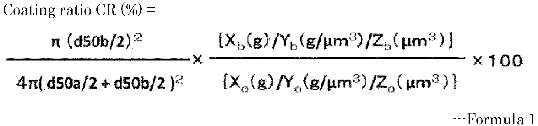
Applications Claiming Priority (4)
| Application Number | Priority Date | Filing Date | Title |
|---|---|---|---|
| JP2019141316 | 2019-07-31 | ||
| JP2019141318 | 2019-07-31 | ||
| JP2020126993A JP7540226B2 (en) | 2019-07-31 | 2020-07-28 | Composite particles, composite particles for forming liquid-encapsulated particles, liquid-encapsulated particles, and method for producing liquid-encapsulated particles |
| JP2020127046A JP7524654B2 (en) | 2019-07-31 | 2020-07-28 | Biocatalyst-containing material, biocatalyst-containing material manufacturing apparatus, and biocatalyst-containing material manufacturing method |
Publications (2)
| Publication Number | Publication Date |
|---|---|
| EP3771488A1 true EP3771488A1 (en) | 2021-02-03 |
| EP3771488B1 EP3771488B1 (en) | 2024-09-04 |
Family
ID=71846332
Family Applications (1)
| Application Number | Title | Priority Date | Filing Date |
|---|---|---|---|
| EP20188462.4A Active EP3771488B1 (en) | 2019-07-31 | 2020-07-29 | Composite particles, composite particles for forming liquid-encapsulating particles, liquid-encapsulating particles, method for producing liquid-encapsulating particles, biocatalyst-containing material and biocatalyst-containing material producing apparatus, and |
Country Status (3)
| Country | Link |
|---|---|
| US (1) | US11795276B2 (en) |
| EP (1) | EP3771488B1 (en) |
| CN (1) | CN112300642B (en) |
Families Citing this family (1)
| Publication number | Priority date | Publication date | Assignee | Title |
|---|---|---|---|---|
| WO2022260156A1 (en) * | 2021-06-11 | 2022-12-15 | 国立大学法人 鹿児島大学 | Capsule production method and capsule production device |
Citations (5)
| Publication number | Priority date | Publication date | Assignee | Title |
|---|---|---|---|---|
| WO1986002093A1 (en) * | 1984-10-03 | 1986-04-10 | Torobin Leonard B | Hollow porous microsphere bioreactors and biochemical processes using same |
| JP2005202133A (en) * | 2004-01-15 | 2005-07-28 | Fuji Xerox Co Ltd | Electrostatic latent image developing two-component developer and image forming method |
| JP2014214286A (en) * | 2013-04-30 | 2014-11-17 | サンノプコ株式会社 | Hydraulic fluid |
| WO2015129903A1 (en) | 2014-02-25 | 2015-09-03 | 住友化学株式会社 | Granular adhesive |
| US20160223928A1 (en) * | 2015-01-30 | 2016-08-04 | Samsung Electronics Co., Ltd. | Complex particle, external additive for toner and method of preparing complex particle |
Family Cites Families (6)
| Publication number | Priority date | Publication date | Assignee | Title |
|---|---|---|---|---|
| US7090868B2 (en) * | 2002-09-13 | 2006-08-15 | University Of Florida | Materials and methods for drug delivery and uptake |
| CN101415654A (en) * | 2003-07-14 | 2009-04-22 | 苏珀尔西尔有限公司 | Hydrophobic composites and particles and their applications |
| CN105400108A (en) | 2014-09-04 | 2016-03-16 | 株式会社理光 | Water-decomposable resin composition and support material for use in modeling |
| CN108137754B (en) | 2015-09-15 | 2021-01-22 | 株式会社理光 | Polymers, resin compositions, dimming materials, optical waveguide materials, athermal optical elements, color display elements and optical materials |
| JP6919248B2 (en) | 2016-07-27 | 2021-08-18 | 株式会社リコー | Multilayer films, multilayer film complexes, optics, and windows |
| JP2018154785A (en) | 2017-03-21 | 2018-10-04 | 株式会社リコー | Polymer composition, and optical material |
-
2020
- 2020-07-29 EP EP20188462.4A patent/EP3771488B1/en active Active
- 2020-07-30 US US16/943,570 patent/US11795276B2/en active Active
- 2020-07-31 CN CN202010755804.8A patent/CN112300642B/en active Active
Patent Citations (5)
| Publication number | Priority date | Publication date | Assignee | Title |
|---|---|---|---|---|
| WO1986002093A1 (en) * | 1984-10-03 | 1986-04-10 | Torobin Leonard B | Hollow porous microsphere bioreactors and biochemical processes using same |
| JP2005202133A (en) * | 2004-01-15 | 2005-07-28 | Fuji Xerox Co Ltd | Electrostatic latent image developing two-component developer and image forming method |
| JP2014214286A (en) * | 2013-04-30 | 2014-11-17 | サンノプコ株式会社 | Hydraulic fluid |
| WO2015129903A1 (en) | 2014-02-25 | 2015-09-03 | 住友化学株式会社 | Granular adhesive |
| US20160223928A1 (en) * | 2015-01-30 | 2016-08-04 | Samsung Electronics Co., Ltd. | Complex particle, external additive for toner and method of preparing complex particle |
Non-Patent Citations (4)
| Title |
|---|
| CHEN J H ET AL: "Synthesis of ZnO/polystyrene composites particles by Pickering emulsion polymerization", EUROPEAN POLYMER JOURNAL, PERGAMON PRESS LTD OXFORD, GB, vol. 44, no. 10, 31 October 2008 (2008-10-31), pages 3271 - 3279, XP025474318, ISSN: 0014-3057, [retrieved on 20080724], DOI: 10.1016/J.EURPOLYMJ.2008.07.023 * |
| COLLOIDS AND SURFACES B: BIOINTERFACES, vol. 106, 2013, pages 187 - 190 |
| J. SOC. COSMET. CHEM. JPN. REPORT, vol. 42, no. 4, 2008, pages 313 - 318 |
| PROC. R. SOC. LOND. B, vol. 269, 2002, pages 1211 - 1215 |
Also Published As
| Publication number | Publication date |
|---|---|
| US20210032414A1 (en) | 2021-02-04 |
| US11795276B2 (en) | 2023-10-24 |
| EP3771488B1 (en) | 2024-09-04 |
| CN112300642A (en) | 2021-02-02 |
| CN112300642B (en) | 2022-03-22 |
Similar Documents
| Publication | Publication Date | Title |
|---|---|---|
| Schutyser et al. | Gaining insight on spray drying behavior of foods via single droplet drying analyses | |
| DE69738409T2 (en) | Process for the preparation of surfaces with low binding affinity | |
| DE69230318T3 (en) | REAGENT COMPOSITIONS FOR ANALYTICAL TESTS | |
| Czerniak et al. | Improvement of oxidative stability of menhaden fish oil by microencapsulation within biocapsules formed of yeast cells | |
| EP3402457B1 (en) | Protein cage-stabilized pickering emulsions and the use thereof | |
| Yang et al. | An update of moisture barrier coating for drug delivery | |
| EP3771488B1 (en) | Composite particles, composite particles for forming liquid-encapsulating particles, liquid-encapsulating particles, method for producing liquid-encapsulating particles, biocatalyst-containing material and biocatalyst-containing material producing apparatus, and | |
| US20110306581A1 (en) | Stable perfluorocarbon emulsion for use as an artificial oxygen carrier | |
| EP3430072B1 (en) | Method for purifying poloxamers | |
| US11555215B2 (en) | Electrospun fibers for protein stabilization and storage | |
| Pachuau et al. | A study on the effects of different surfactants on Ethylcellulose microspheres | |
| DE69634802T2 (en) | BIOSENSORS WITH MEMBRANE | |
| US20070015137A1 (en) | Microfluid device and method of producing diffusively built gradients | |
| EP4097409B1 (en) | Electrostatic spray drying of microorganisms | |
| Benkocká et al. | Nanocomposite of polystyrene foil grafted with metallaboranes for antimicrobial activity | |
| JP7635513B2 (en) | Liquid for liquid marble, liquid marble, method and device for producing liquid marble, and bioreactor | |
| Mishra et al. | Applicability of spray drying technique to prepare nano-micro carriers: A review | |
| JP7524654B2 (en) | Biocatalyst-containing material, biocatalyst-containing material manufacturing apparatus, and biocatalyst-containing material manufacturing method | |
| JP7571413B2 (en) | Composite particles, composite particles for forming liquid-encapsulated particles, and liquid-encapsulated particles | |
| JP7540226B2 (en) | Composite particles, composite particles for forming liquid-encapsulated particles, liquid-encapsulated particles, and method for producing liquid-encapsulated particles | |
| US20230302454A1 (en) | Sample collection containers, processes and collected samples | |
| CN110625132A (en) | Sulfhydrylation amphiphilic carbon residue/nano-silver compound, preparation method thereof and antibacterial leather | |
| EP4225277B1 (en) | Mesoporous nanoparticle system to increase the biofilm eradication activity by means of the carrying and the administration of at least one active ingredient and related production method | |
| Garbaczewska et al. | Dispersion of lambda-cyhalothrin in micro-emulsion of polystyrene | |
| RU2440098C2 (en) | Preparation containing biologically active substances |
Legal Events
| Date | Code | Title | Description |
|---|---|---|---|
| PUAI | Public reference made under article 153(3) epc to a published international application that has entered the european phase |
Free format text: ORIGINAL CODE: 0009012 |
|
| STAA | Information on the status of an ep patent application or granted ep patent |
Free format text: STATUS: REQUEST FOR EXAMINATION WAS MADE |
|
| 17P | Request for examination filed |
Effective date: 20200729 |
|
| AK | Designated contracting states |
Kind code of ref document: A1 Designated state(s): AL AT BE BG CH CY CZ DE DK EE ES FI FR GB GR HR HU IE IS IT LI LT LU LV MC MK MT NL NO PL PT RO RS SE SI SK SM TR |
|
| AX | Request for extension of the european patent |
Extension state: BA ME |
|
| STAA | Information on the status of an ep patent application or granted ep patent |
Free format text: STATUS: EXAMINATION IS IN PROGRESS |
|
| 17Q | First examination report despatched |
Effective date: 20210809 |
|
| GRAP | Despatch of communication of intention to grant a patent |
Free format text: ORIGINAL CODE: EPIDOSNIGR1 |
|
| STAA | Information on the status of an ep patent application or granted ep patent |
Free format text: STATUS: GRANT OF PATENT IS INTENDED |
|
| INTG | Intention to grant announced |
Effective date: 20240411 |
|
| GRAS | Grant fee paid |
Free format text: ORIGINAL CODE: EPIDOSNIGR3 |
|
| P01 | Opt-out of the competence of the unified patent court (upc) registered |
Effective date: 20240528 |
|
| GRAA | (expected) grant |
Free format text: ORIGINAL CODE: 0009210 |
|
| STAA | Information on the status of an ep patent application or granted ep patent |
Free format text: STATUS: THE PATENT HAS BEEN GRANTED |
|
| AK | Designated contracting states |
Kind code of ref document: B1 Designated state(s): AL AT BE BG CH CY CZ DE DK EE ES FI FR GB GR HR HU IE IS IT LI LT LU LV MC MK MT NL NO PL PT RO RS SE SI SK SM TR |
|
| REG | Reference to a national code |
Ref country code: GB Ref legal event code: FG4D |
|
| REG | Reference to a national code |
Ref country code: CH Ref legal event code: EP |
|
| REG | Reference to a national code |
Ref country code: IE Ref legal event code: FG4D |
|
| REG | Reference to a national code |
Ref country code: DE Ref legal event code: R096 Ref document number: 602020036963 Country of ref document: DE |
|
| REG | Reference to a national code |
Ref country code: LT Ref legal event code: MG9D |
|
| REG | Reference to a national code |
Ref country code: NL Ref legal event code: MP Effective date: 20240904 |
|
| PG25 | Lapsed in a contracting state [announced via postgrant information from national office to epo] |
Ref country code: NO Free format text: LAPSE BECAUSE OF FAILURE TO SUBMIT A TRANSLATION OF THE DESCRIPTION OR TO PAY THE FEE WITHIN THE PRESCRIBED TIME-LIMIT Effective date: 20241204 |
|
| PG25 | Lapsed in a contracting state [announced via postgrant information from national office to epo] |
Ref country code: GR Free format text: LAPSE BECAUSE OF FAILURE TO SUBMIT A TRANSLATION OF THE DESCRIPTION OR TO PAY THE FEE WITHIN THE PRESCRIBED TIME-LIMIT Effective date: 20241205 Ref country code: FI Free format text: LAPSE BECAUSE OF FAILURE TO SUBMIT A TRANSLATION OF THE DESCRIPTION OR TO PAY THE FEE WITHIN THE PRESCRIBED TIME-LIMIT Effective date: 20240904 Ref country code: PL Free format text: LAPSE BECAUSE OF FAILURE TO SUBMIT A TRANSLATION OF THE DESCRIPTION OR TO PAY THE FEE WITHIN THE PRESCRIBED TIME-LIMIT Effective date: 20240904 |
|
| PG25 | Lapsed in a contracting state [announced via postgrant information from national office to epo] |
Ref country code: BG Free format text: LAPSE BECAUSE OF FAILURE TO SUBMIT A TRANSLATION OF THE DESCRIPTION OR TO PAY THE FEE WITHIN THE PRESCRIBED TIME-LIMIT Effective date: 20240904 |
|
| PG25 | Lapsed in a contracting state [announced via postgrant information from national office to epo] |
Ref country code: LV Free format text: LAPSE BECAUSE OF FAILURE TO SUBMIT A TRANSLATION OF THE DESCRIPTION OR TO PAY THE FEE WITHIN THE PRESCRIBED TIME-LIMIT Effective date: 20240904 |
|
| PG25 | Lapsed in a contracting state [announced via postgrant information from national office to epo] |
Ref country code: HR Free format text: LAPSE BECAUSE OF FAILURE TO SUBMIT A TRANSLATION OF THE DESCRIPTION OR TO PAY THE FEE WITHIN THE PRESCRIBED TIME-LIMIT Effective date: 20240904 |
|
| PG25 | Lapsed in a contracting state [announced via postgrant information from national office to epo] |
Ref country code: ES Free format text: LAPSE BECAUSE OF FAILURE TO SUBMIT A TRANSLATION OF THE DESCRIPTION OR TO PAY THE FEE WITHIN THE PRESCRIBED TIME-LIMIT Effective date: 20240904 Ref country code: RS Free format text: LAPSE BECAUSE OF FAILURE TO SUBMIT A TRANSLATION OF THE DESCRIPTION OR TO PAY THE FEE WITHIN THE PRESCRIBED TIME-LIMIT Effective date: 20241204 |
|
| PG25 | Lapsed in a contracting state [announced via postgrant information from national office to epo] |
Ref country code: RS Free format text: LAPSE BECAUSE OF FAILURE TO SUBMIT A TRANSLATION OF THE DESCRIPTION OR TO PAY THE FEE WITHIN THE PRESCRIBED TIME-LIMIT Effective date: 20241204 Ref country code: PL Free format text: LAPSE BECAUSE OF FAILURE TO SUBMIT A TRANSLATION OF THE DESCRIPTION OR TO PAY THE FEE WITHIN THE PRESCRIBED TIME-LIMIT Effective date: 20240904 Ref country code: NO Free format text: LAPSE BECAUSE OF FAILURE TO SUBMIT A TRANSLATION OF THE DESCRIPTION OR TO PAY THE FEE WITHIN THE PRESCRIBED TIME-LIMIT Effective date: 20241204 Ref country code: LV Free format text: LAPSE BECAUSE OF FAILURE TO SUBMIT A TRANSLATION OF THE DESCRIPTION OR TO PAY THE FEE WITHIN THE PRESCRIBED TIME-LIMIT Effective date: 20240904 Ref country code: HR Free format text: LAPSE BECAUSE OF FAILURE TO SUBMIT A TRANSLATION OF THE DESCRIPTION OR TO PAY THE FEE WITHIN THE PRESCRIBED TIME-LIMIT Effective date: 20240904 Ref country code: GR Free format text: LAPSE BECAUSE OF FAILURE TO SUBMIT A TRANSLATION OF THE DESCRIPTION OR TO PAY THE FEE WITHIN THE PRESCRIBED TIME-LIMIT Effective date: 20241205 Ref country code: FI Free format text: LAPSE BECAUSE OF FAILURE TO SUBMIT A TRANSLATION OF THE DESCRIPTION OR TO PAY THE FEE WITHIN THE PRESCRIBED TIME-LIMIT Effective date: 20240904 Ref country code: ES Free format text: LAPSE BECAUSE OF FAILURE TO SUBMIT A TRANSLATION OF THE DESCRIPTION OR TO PAY THE FEE WITHIN THE PRESCRIBED TIME-LIMIT Effective date: 20240904 Ref country code: BG Free format text: LAPSE BECAUSE OF FAILURE TO SUBMIT A TRANSLATION OF THE DESCRIPTION OR TO PAY THE FEE WITHIN THE PRESCRIBED TIME-LIMIT Effective date: 20240904 |
|
| REG | Reference to a national code |
Ref country code: AT Ref legal event code: MK05 Ref document number: 1719783 Country of ref document: AT Kind code of ref document: T Effective date: 20240904 |
|
| PG25 | Lapsed in a contracting state [announced via postgrant information from national office to epo] |
Ref country code: NL Free format text: LAPSE BECAUSE OF FAILURE TO SUBMIT A TRANSLATION OF THE DESCRIPTION OR TO PAY THE FEE WITHIN THE PRESCRIBED TIME-LIMIT Effective date: 20240904 |
|
| PG25 | Lapsed in a contracting state [announced via postgrant information from national office to epo] |
Ref country code: PT Free format text: LAPSE BECAUSE OF FAILURE TO SUBMIT A TRANSLATION OF THE DESCRIPTION OR TO PAY THE FEE WITHIN THE PRESCRIBED TIME-LIMIT Effective date: 20250106 Ref country code: IS Free format text: LAPSE BECAUSE OF FAILURE TO SUBMIT A TRANSLATION OF THE DESCRIPTION OR TO PAY THE FEE WITHIN THE PRESCRIBED TIME-LIMIT Effective date: 20250104 |
|
| PG25 | Lapsed in a contracting state [announced via postgrant information from national office to epo] |
Ref country code: RO Free format text: LAPSE BECAUSE OF FAILURE TO SUBMIT A TRANSLATION OF THE DESCRIPTION OR TO PAY THE FEE WITHIN THE PRESCRIBED TIME-LIMIT Effective date: 20240904 Ref country code: SM Free format text: LAPSE BECAUSE OF FAILURE TO SUBMIT A TRANSLATION OF THE DESCRIPTION OR TO PAY THE FEE WITHIN THE PRESCRIBED TIME-LIMIT Effective date: 20240904 |
|
| PG25 | Lapsed in a contracting state [announced via postgrant information from national office to epo] |
Ref country code: EE Free format text: LAPSE BECAUSE OF FAILURE TO SUBMIT A TRANSLATION OF THE DESCRIPTION OR TO PAY THE FEE WITHIN THE PRESCRIBED TIME-LIMIT Effective date: 20240904 Ref country code: AT Free format text: LAPSE BECAUSE OF FAILURE TO SUBMIT A TRANSLATION OF THE DESCRIPTION OR TO PAY THE FEE WITHIN THE PRESCRIBED TIME-LIMIT Effective date: 20240904 |
|
| PG25 | Lapsed in a contracting state [announced via postgrant information from national office to epo] |
Ref country code: CZ Free format text: LAPSE BECAUSE OF FAILURE TO SUBMIT A TRANSLATION OF THE DESCRIPTION OR TO PAY THE FEE WITHIN THE PRESCRIBED TIME-LIMIT Effective date: 20240904 |
|
| PG25 | Lapsed in a contracting state [announced via postgrant information from national office to epo] |
Ref country code: IT Free format text: LAPSE BECAUSE OF FAILURE TO SUBMIT A TRANSLATION OF THE DESCRIPTION OR TO PAY THE FEE WITHIN THE PRESCRIBED TIME-LIMIT Effective date: 20240904 Ref country code: SK Free format text: LAPSE BECAUSE OF FAILURE TO SUBMIT A TRANSLATION OF THE DESCRIPTION OR TO PAY THE FEE WITHIN THE PRESCRIBED TIME-LIMIT Effective date: 20240904 |
|
| REG | Reference to a national code |
Ref country code: DE Ref legal event code: R097 Ref document number: 602020036963 Country of ref document: DE |
|
| PG25 | Lapsed in a contracting state [announced via postgrant information from national office to epo] |
Ref country code: DK Free format text: LAPSE BECAUSE OF FAILURE TO SUBMIT A TRANSLATION OF THE DESCRIPTION OR TO PAY THE FEE WITHIN THE PRESCRIBED TIME-LIMIT Effective date: 20240904 |
|
| PLBE | No opposition filed within time limit |
Free format text: ORIGINAL CODE: 0009261 |
|
| STAA | Information on the status of an ep patent application or granted ep patent |
Free format text: STATUS: NO OPPOSITION FILED WITHIN TIME LIMIT |
|
| 26N | No opposition filed |
Effective date: 20250605 |
|
| PG25 | Lapsed in a contracting state [announced via postgrant information from national office to epo] |
Ref country code: SE Free format text: LAPSE BECAUSE OF FAILURE TO SUBMIT A TRANSLATION OF THE DESCRIPTION OR TO PAY THE FEE WITHIN THE PRESCRIBED TIME-LIMIT Effective date: 20240904 |
|
| REG | Reference to a national code |
Ref country code: DE Ref legal event code: R119 Ref document number: 602020036963 Country of ref document: DE |
|
| REG | Reference to a national code |
Ref country code: CH Ref legal event code: H13 Free format text: ST27 STATUS EVENT CODE: U-0-0-H10-H13 (AS PROVIDED BY THE NATIONAL OFFICE) Effective date: 20260224 |
|
| PG25 | Lapsed in a contracting state [announced via postgrant information from national office to epo] |
Ref country code: LU Free format text: LAPSE BECAUSE OF NON-PAYMENT OF DUE FEES Effective date: 20250729 |
|
| GBPC | Gb: european patent ceased through non-payment of renewal fee |
Effective date: 20250729 |
|
| REG | Reference to a national code |
Ref country code: BE Ref legal event code: MM Effective date: 20250731 |
|
| PG25 | Lapsed in a contracting state [announced via postgrant information from national office to epo] |
Ref country code: GB Free format text: LAPSE BECAUSE OF NON-PAYMENT OF DUE FEES Effective date: 20250729 |
|
| PG25 | Lapsed in a contracting state [announced via postgrant information from national office to epo] |
Ref country code: DE Free format text: LAPSE BECAUSE OF NON-PAYMENT OF DUE FEES Effective date: 20260203 |
|
| PG25 | Lapsed in a contracting state [announced via postgrant information from national office to epo] |
Ref country code: BE Free format text: LAPSE BECAUSE OF NON-PAYMENT OF DUE FEES Effective date: 20250731 |
|
| PG25 | Lapsed in a contracting state [announced via postgrant information from national office to epo] |
Ref country code: FR Free format text: LAPSE BECAUSE OF NON-PAYMENT OF DUE FEES Effective date: 20250731 |
|
| PG25 | Lapsed in a contracting state [announced via postgrant information from national office to epo] |
Ref country code: CH Free format text: LAPSE BECAUSE OF NON-PAYMENT OF DUE FEES Effective date: 20250731 |