EP3771018A1 - Electrode assembly - Google Patents
Electrode assembly Download PDFInfo
- Publication number
- EP3771018A1 EP3771018A1 EP20759033.2A EP20759033A EP3771018A1 EP 3771018 A1 EP3771018 A1 EP 3771018A1 EP 20759033 A EP20759033 A EP 20759033A EP 3771018 A1 EP3771018 A1 EP 3771018A1
- Authority
- EP
- European Patent Office
- Prior art keywords
- positive electrode
- shrinkage film
- electrode
- electrode assembly
- shrinkage
- Prior art date
- Legal status (The legal status is an assumption and is not a legal conclusion. Google has not performed a legal analysis and makes no representation as to the accuracy of the status listed.)
- Granted
Links
Images


Classifications
-
- H—ELECTRICITY
- H01—ELECTRIC ELEMENTS
- H01M—PROCESSES OR MEANS, e.g. BATTERIES, FOR THE DIRECT CONVERSION OF CHEMICAL ENERGY INTO ELECTRICAL ENERGY
- H01M50/00—Constructional details or processes of manufacture of the non-active parts of electrochemical cells other than fuel cells, e.g. hybrid cells
- H01M50/40—Separators; Membranes; Diaphragms; Spacing elements inside cells
- H01M50/489—Separators, membranes, diaphragms or spacing elements inside the cells, characterised by their physical properties, e.g. swelling degree, hydrophilicity or shut down properties
-
- H—ELECTRICITY
- H01—ELECTRIC ELEMENTS
- H01M—PROCESSES OR MEANS, e.g. BATTERIES, FOR THE DIRECT CONVERSION OF CHEMICAL ENERGY INTO ELECTRICAL ENERGY
- H01M10/00—Secondary cells; Manufacture thereof
- H01M10/05—Accumulators with non-aqueous electrolyte
- H01M10/058—Construction or manufacture
- H01M10/0585—Construction or manufacture of accumulators having only flat construction elements, i.e. flat positive electrodes, flat negative electrodes and flat separators
-
- H—ELECTRICITY
- H01—ELECTRIC ELEMENTS
- H01M—PROCESSES OR MEANS, e.g. BATTERIES, FOR THE DIRECT CONVERSION OF CHEMICAL ENERGY INTO ELECTRICAL ENERGY
- H01M10/00—Secondary cells; Manufacture thereof
- H01M10/05—Accumulators with non-aqueous electrolyte
- H01M10/052—Li-accumulators
-
- H—ELECTRICITY
- H01—ELECTRIC ELEMENTS
- H01M—PROCESSES OR MEANS, e.g. BATTERIES, FOR THE DIRECT CONVERSION OF CHEMICAL ENERGY INTO ELECTRICAL ENERGY
- H01M10/00—Secondary cells; Manufacture thereof
- H01M10/42—Methods or arrangements for servicing or maintenance of secondary cells or secondary half-cells
- H01M10/4235—Safety or regulating additives or arrangements in electrodes, separators or electrolyte
-
- H—ELECTRICITY
- H01—ELECTRIC ELEMENTS
- H01M—PROCESSES OR MEANS, e.g. BATTERIES, FOR THE DIRECT CONVERSION OF CHEMICAL ENERGY INTO ELECTRICAL ENERGY
- H01M4/00—Electrodes
- H01M4/02—Electrodes composed of, or comprising, active material
- H01M4/13—Electrodes for accumulators with non-aqueous electrolyte, e.g. for lithium-accumulators; Processes of manufacture thereof
- H01M4/131—Electrodes based on mixed oxides or hydroxides, or on mixtures of oxides or hydroxides, e.g. LiCoOx
-
- H—ELECTRICITY
- H01—ELECTRIC ELEMENTS
- H01M—PROCESSES OR MEANS, e.g. BATTERIES, FOR THE DIRECT CONVERSION OF CHEMICAL ENERGY INTO ELECTRICAL ENERGY
- H01M4/00—Electrodes
- H01M4/02—Electrodes composed of, or comprising, active material
- H01M4/36—Selection of substances as active materials, active masses, active liquids
- H01M4/48—Selection of substances as active materials, active masses, active liquids of inorganic oxides or hydroxides
- H01M4/50—Selection of substances as active materials, active masses, active liquids of inorganic oxides or hydroxides of manganese
- H01M4/505—Selection of substances as active materials, active masses, active liquids of inorganic oxides or hydroxides of manganese of mixed oxides or hydroxides containing manganese for inserting or intercalating light metals, e.g. LiMn2O4 or LiMn2OxFy
-
- H—ELECTRICITY
- H01—ELECTRIC ELEMENTS
- H01M—PROCESSES OR MEANS, e.g. BATTERIES, FOR THE DIRECT CONVERSION OF CHEMICAL ENERGY INTO ELECTRICAL ENERGY
- H01M4/00—Electrodes
- H01M4/02—Electrodes composed of, or comprising, active material
- H01M4/36—Selection of substances as active materials, active masses, active liquids
- H01M4/48—Selection of substances as active materials, active masses, active liquids of inorganic oxides or hydroxides
- H01M4/52—Selection of substances as active materials, active masses, active liquids of inorganic oxides or hydroxides of nickel, cobalt or iron
- H01M4/525—Selection of substances as active materials, active masses, active liquids of inorganic oxides or hydroxides of nickel, cobalt or iron of mixed oxides or hydroxides containing iron, cobalt or nickel for inserting or intercalating light metals, e.g. LiNiO2, LiCoO2 or LiCoOxFy
-
- H—ELECTRICITY
- H01—ELECTRIC ELEMENTS
- H01M—PROCESSES OR MEANS, e.g. BATTERIES, FOR THE DIRECT CONVERSION OF CHEMICAL ENERGY INTO ELECTRICAL ENERGY
- H01M50/00—Constructional details or processes of manufacture of the non-active parts of electrochemical cells other than fuel cells, e.g. hybrid cells
- H01M50/50—Current conducting connections for cells or batteries
- H01M50/572—Means for preventing undesired use or discharge
- H01M50/574—Devices or arrangements for the interruption of current
- H01M50/581—Devices or arrangements for the interruption of current in response to temperature
-
- H—ELECTRICITY
- H01—ELECTRIC ELEMENTS
- H01M—PROCESSES OR MEANS, e.g. BATTERIES, FOR THE DIRECT CONVERSION OF CHEMICAL ENERGY INTO ELECTRICAL ENERGY
- H01M4/00—Electrodes
- H01M4/02—Electrodes composed of, or comprising, active material
- H01M2004/026—Electrodes composed of, or comprising, active material characterised by the polarity
- H01M2004/027—Negative electrodes
-
- H—ELECTRICITY
- H01—ELECTRIC ELEMENTS
- H01M—PROCESSES OR MEANS, e.g. BATTERIES, FOR THE DIRECT CONVERSION OF CHEMICAL ENERGY INTO ELECTRICAL ENERGY
- H01M4/00—Electrodes
- H01M4/02—Electrodes composed of, or comprising, active material
- H01M2004/026—Electrodes composed of, or comprising, active material characterised by the polarity
- H01M2004/028—Positive electrodes
-
- H—ELECTRICITY
- H01—ELECTRIC ELEMENTS
- H01M—PROCESSES OR MEANS, e.g. BATTERIES, FOR THE DIRECT CONVERSION OF CHEMICAL ENERGY INTO ELECTRICAL ENERGY
- H01M2300/00—Electrolytes
- H01M2300/0017—Non-aqueous electrolytes
- H01M2300/0065—Solid electrolytes
- H01M2300/0068—Solid electrolytes inorganic
-
- Y—GENERAL TAGGING OF NEW TECHNOLOGICAL DEVELOPMENTS; GENERAL TAGGING OF CROSS-SECTIONAL TECHNOLOGIES SPANNING OVER SEVERAL SECTIONS OF THE IPC; TECHNICAL SUBJECTS COVERED BY FORMER USPC CROSS-REFERENCE ART COLLECTIONS [XRACs] AND DIGESTS
- Y02—TECHNOLOGIES OR APPLICATIONS FOR MITIGATION OR ADAPTATION AGAINST CLIMATE CHANGE
- Y02E—REDUCTION OF GREENHOUSE GAS [GHG] EMISSIONS, RELATED TO ENERGY GENERATION, TRANSMISSION OR DISTRIBUTION
- Y02E60/00—Enabling technologies; Technologies with a potential or indirect contribution to GHG emissions mitigation
- Y02E60/10—Energy storage using batteries
-
- Y—GENERAL TAGGING OF NEW TECHNOLOGICAL DEVELOPMENTS; GENERAL TAGGING OF CROSS-SECTIONAL TECHNOLOGIES SPANNING OVER SEVERAL SECTIONS OF THE IPC; TECHNICAL SUBJECTS COVERED BY FORMER USPC CROSS-REFERENCE ART COLLECTIONS [XRACs] AND DIGESTS
- Y02—TECHNOLOGIES OR APPLICATIONS FOR MITIGATION OR ADAPTATION AGAINST CLIMATE CHANGE
- Y02P—CLIMATE CHANGE MITIGATION TECHNOLOGIES IN THE PRODUCTION OR PROCESSING OF GOODS
- Y02P70/00—Climate change mitigation technologies in the production process for final industrial or consumer products
- Y02P70/50—Manufacturing or production processes characterised by the final manufactured product
Definitions
- the present invention relates to an electrode assembly in which a negative electrode, a separator, and a positive electrode are repeatedly stacked, and more particularly, to an electrode assembly that is capable of preventing ignition due to thermal runaway from occurring.
- Batteries storing electrical energy may be generally classified into primary batteries and a secondary batteries.
- a primary battery is a disposable consumable battery.
- a secondary battery is a chargeable battery that is manufactured by using a material in which oxidation and reduction processes between current and the material are capable of being repeated. That is, when the reduction reaction to the material is performed by the current, power is charged, and when the oxidation reaction to the material is performed by the current, power is discharged. Here, such the charging-discharging are repeatedly performed.
- lithium secondary batteries are generally manufactured by mounting an electrode assembly, in which a positive electrode (cathode), a separator, and a negative electrode (anode) are stacked, in a case.
- a process in which lithium ions are intercalated and deintercalated from lithium metal oxide to the negative electrode, is repeated to charge and discharge the lithium secondary batteries.
- the electrode assembly may be manufactured so that a positive electrode 1/a separator 3/a negative electrode 2 are stacked repeatedly.
- the electrode assembly is accommodated in a can such as a cylindrical can or a prismatic case.
- a side view of the electrode assembly is illustrated, the positive electrode 1 of the electrode assembly is coated with a positive electrode active material 1b on both surfaces of a positive electrode collector 1a, and the negative electrode 2 is coated with a negative electrode active material 2b on both surfaces of the negative electrode collector 2a.
- a negative electrode tab (not shown) and a positive electrode tab (not shown) protrude from the negative electrode collector 2a and the positive electrode collector 1a in the negative electrode 2 and the positive electrode 1 so that current flows through the negative electrode tab and the positive electrode tab, respectively.
- NCM nickel (Ni), cobalt (Co), and manganese (Mn)
- the NCM-based secondary battery has a problem that, when a nickel content relatively increases, the capacity increases, but the thermal stability decreases, and thus, the possibility of ignition also increases.
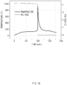
- FIG. 1b is a graph illustrating a change in temperature and pressure depending on a time when thermal runaway occurs in an electrode assembly according to the related art.
- a positive electrode stacked in the electrode assembly is coated with a positive electrode active material having a composition ratio of 8:1:1 of nickel, cobalt, and manganese, and experimental conditions are provided to measure a change in temperature and voltage (vertical axis) to a time (horizontal axis) when heat is applied at a constant rate.
- a main object of the present invention is to provide an electrode assembly that is capable of prevent ignition due to thermal runaway from occurring even if a positive electrode active material having a high nickel content (for example, an NCM811 active material) is used.
- a positive electrode active material having a high nickel content for example, an NCM811 active material
- the flow of the microcurrent may reduce a state of charge (charging amount : SOC) of the electrode assembly to improve stability.
- the shrinkage film may be manufactured to be restored to its original area when the temperature drops down below the specific temperature.
- the shrinkage film may be manufactured so as not to be restored even if the temperature drops down below the specific temperature. This may be determined according to a design of the electrode assembly.
- the flow of the microcurrent may be interrupted or minimized to allow the electrode assembly to be in a stable state and prevent short circuit due to a flow of large current by external factors from occurring.
- the shrinkage film according to the present invention may be manufactured to contain a material that is shrunk from a crystal structure.
- the material in which the shrinkage occurs from the crystal structure may be zirconium tungstate (ZrW 2 O 8 ).
- an NCM positive electrode active material which contains nickel, cobalt, and manganese, may be applied on a surface of a positive electrode collector.
- the NCM positive electrode active material may have a weight ratio of nickel greater than that of each of cobalt and manganese.
- the NCM positive electrode active material may be NCM811 having a content (composition ratio) of nickel, cobalt, and manganese of 8:1:1 or NCM622 having a composition ratio of 6:2:2.
- a single-sided positive electrode coated with a positive electrode active material on only one surface of a positive electrode collector may be disposed at the outermost layer, and the shrinkage film may be stacked to contact the single-sided positive electrode disposed at the outermost layer.
- the single-sided positive electrode disposed at the outermost layer may be stacked so that the positive electrode collector faces outward, and the positive electrode active material faces the shrinkage film.
- the shrinkage film may be stacked at only a position contacting the single-sided positive electrode and may be stacked at one or more positions between a double-sided positive electrode coated with the positive electrode active material on both surfaces of the positive electrode collector and a double-sided negative electrode coated with a negative electrode active material on both surfaces of a negative electrode collector in addition to the position contacting the single-sided positive electrode.
- the shrinkage film may not be stacked at the outermost side, wherein the shrinkage film may be stacked at one or more positions between the double-sided positive electrode coated with the positive electrode active material on both the surfaces of the positive electrode collector and the double-sided negative electrode coated with the negative electrode active material on both the surfaces of the negative electrode collector.
- the electrode assembly as described above may additionally provide a secondary battery embedded in the case.
- the flow of the microcurrent may be allowed to reduce the charging rate of the electrode assembly, thereby improving the thermal stability (reducing the possibility of the ignition).
- the shrinkage film according to the present invention contains the material that causes the shrinkage from the crystal structure, the shrinkage may uniformly occur as a whole.
- a single-sided positive electrode on which a positive electrode active material is applied to only one surface of a positive electrode collector may be disposed at the outermost layer to prevent lithium from being precipitated.
- the present invention relates to an electrode assembly in which a positive electrode, a separator, and a negative electrode are repeatedly stacked and has a feature in which ignition due to thermal runaway is suppressed by using a shrinkage film that is shrunk in area when heat is applied.
- an electrode assembly according to the present invention comprises a shrinkage film 31 that is shrunk in area at a specific temperature or more.
- the shrinkage film 31 is disposed instead of the separator 30 at each of the uppermost side and the lowermost side among positions at which the separators 30 are disposed.
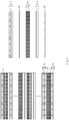
- FIG. 2 which illustrates a side view of the electrode assembly in which the shrinkage film 31 is disposed instead of the separator 30 at each of the uppermost and lowermost sides among the positions at which the separators 30 are disposed
- the shrinkage film 31 is stacked instead of the separator 30 at at least one or more positions between the positive electrode 10 and the negative electrode 20, and also, the shrinkage film 31 is disposed at stacking positions of the separators disposed at the outermost sides.
- the shrinkage film 31 may be configured to separate the positive electrode 10 and the negative electrode 10 from each other in a normal temperature range as long as the shrinkage film 31 has a sufficient thermal shrinkage rate and also allow lithium ions to be conducted, like the separator 30. However, unlike the separator 30, the shrinkage film 31 may block the conduction of the lithium ions. Also, the shrinkage film 31 is manufactured to contain a material that is shrinkable from a crystal structure and thus is shrunk in area when heat is applied at a specific temperature or more.
- the separator 30 since the separator 30 has also a structure in coating layer is applied to a surface of a polymer base material, the separator 30 may have thermal shrinkage according to a molecular bonding structure of the polymer base material and/or the coating layer.
- the thermal shrinkage rate of the separator 30 is considered to be low that is enough to not allow contact between the negative electrode and the positive electrode.
- the separator 30 does not allow the contact between the negative electrode and the positive electrode.
- the shrinkage film 31 allows the contact between the negative electrode and the positive electrode when heat is applied at a specific temperature or more.
- FIG. 3 which illustrates states before and after the positive electrode 10 and the negative electrode 20 contact each other
- the positive electrode 10 and the negative electrode 20 which are adjacent to each other with the shrinkage film 31 therebetween, partially contact each other.
- a positive electrode active material 10a of the positive electrode 10 and a negative electrode active material 20a of the negative electrode 20, which contact each other are illustrated in the drawings, the present invention is not limited thereto.
- the positive electrode collector 10a and the negative electrode collector 20a may contact active materials 10b and 20b, which have opposite polarities, at positions at which the electrode tabs (not shown) that are not coated with the active materials 10b and 20b are formed.
- microcurrent means current flowing through a small area relative to the area of the electrode, but does not mean current having an absolutely small value.
- the meaning of the microcurrent is clear as it means relatively soft short current).
- a material in which the shrinkage occurs from the crystal structure may be zirconium tungstate (ZrW 2 O 8 ).
- the zirconium tungstate is known that atoms are attracted with respect to each other to reduce the overall size when the temperature increases because a natural vibration frequency generated inside the material is very low, and also, it is known that research and development are in progress for use in various fields.
- the shrinkage film 31 containing the zirconium tungstate having the above-described features may be restored to its original area when the thermal runaway is relaxed to drop down to the specific temperature or less according to a content of the zirconium tungstate and the manufacturing method of the shrinkage film 31 or may be manufactured to be maintained in the shrunk state. This may be determined according to a design of the electrode assembly.
- the shrinkage film 31 has to be manufactured to be limited in maximum amount of shrinkage and shrinkage range so as to prevent a short circuit in which large current flows from occurring. Also, the shrinkage film 31 may have no problem in terms of lowering possibility of the ignition even if its original area is not restored after the temperature decreases (since the charging amount is continuously reduced). However, as the temperature decreases after the shrinkage, when the original area is restored as the temperature decreases, or when being wider than the shrunk area even if not the original area, the flow of the microcurrent may be interrupted to more reduce the possibility of the short circuit in which the large current flows.
- the positive electrode 10 is coated with an NCM positive electrode active material 10b containing nickel, cobalt, and manganese on the surface of the positive electrode collector 10a.
- the NCM positive electrode active material 10b has a weight ratio of nickel greater than that of each of cobalt and manganese.
- the NCM positive electrode active material may be NCM811 having a content (composition ratio) of nickel, cobalt, and manganese of 8:1:1 or NCM622 having a composition ratio of 6:2:2.
- the shrinkage film 31 is stacked to contact the single-sided positive electrode 10' disposed at the outermost layer.
- the single-sided positive electrode 10' disposed at the outermost layer is stacked so that the positive electrode collector 10a faces outward, and the positive electrode active material 10b faces the shrinkage film 31.
- the reason in which the single-sided positive electrode 10' is disposed at the outermost layer is because, if the double-sided positive electrode 10 is disposed at the outermost layer, possibility of lithium precipitation occurs between an inner wall of a case, in which the electrode assembly is embedded, and the positive electrode active material disposed at the outermost layer (i.e., when the double-sided positive electrode is disposed at the outermost side, lithium ions deintercalated from the positive electrode active material disposed at the outermost side are not received in the negative electrode but is precipitated).
- the shrinkage film 31 may be stacked at only the position contacting the single-sided positive electrode 10' and also may stacked at one or more positions between the double-sided positive electrode 10 coated with the positive electrode active material 10b on both the surfaces of the positive electrode collector 10a and the double-sided negative electrode 20 coated with the negative electrode active material 20b on both the surfaces of the negative electrode collector 20a in addition to the position contacting the single-sided positive electrode 10'.
- the shrinkage film 31 may be stacked only between the double-sided positive electrode 10 and the double-sided negative electrode 20 except for the position contacting the single-sided positive electrode 10'.
- the shrinkage film 31 may be additionally disposed between a double-sided positive electrode 10 and a double-sided negative electrode 20 in addition to the position contacting the single-sided positive electrode 10'.
- the shrinkage film 31 may be additionally disposed or selectively disposed at the intermediate layer of the electrode assembly, at which a larger amount of heat is generated.
- the stacked position and the number of stacking of the shrinkage film 31 may be adjusted to tune a time point at which reduction of a charging amount by microcurrent starts.
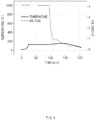
- the thermal runaway may proceed to rise a temperature, a flow of the microcurrent occurs by the shrinkage of the shrinkage film 31 (at a point at which the voltage sharply decreases in the vicinity of a point corresponding to 90 minutes) to reduce the charging amount, thereby preventing the ignition from occurring.
- the electrode assembly as described above may additionally provide a secondary battery embedded in the case.
- the flow of the fine current may be allowed to reduce the charging rate of the electrode assembly, thereby reducing the possibility of the ignition.
- the shrinkage film 31 according to the present invention contains the material that causes the shrinkage from the crystal structure, the shrinkage may uniformly occur as a whole.
- the single-sided positive electrode 10' on which a positive electrode active material is applied to only one surface of a positive electrode collector may be disposed at the outermost layer to prevent lithium from being precipitated.
Landscapes
- Chemical & Material Sciences (AREA)
- Chemical Kinetics & Catalysis (AREA)
- Electrochemistry (AREA)
- General Chemical & Material Sciences (AREA)
- Engineering & Computer Science (AREA)
- Manufacturing & Machinery (AREA)
- Inorganic Chemistry (AREA)
- Materials Engineering (AREA)
- Secondary Cells (AREA)
- Battery Electrode And Active Subsutance (AREA)
- Cell Separators (AREA)
- Electron Tubes For Measurement (AREA)
- Ceramic Capacitors (AREA)
Abstract
Description
- The present application claims the benefit of the priority of Korean Patent Application No.
10-2019-0020424 - The present invention relates to an electrode assembly in which a negative electrode, a separator, and a positive electrode are repeatedly stacked, and more particularly, to an electrode assembly that is capable of preventing ignition due to thermal runaway from occurring.
- Batteries storing electrical energy may be generally classified into primary batteries and a secondary batteries. Such a primary battery is a disposable consumable battery. On the other hand, such a secondary battery is a chargeable battery that is manufactured by using a material in which oxidation and reduction processes between current and the material are capable of being repeated. That is, when the reduction reaction to the material is performed by the current, power is charged, and when the oxidation reaction to the material is performed by the current, power is discharged. Here, such the charging-discharging are repeatedly performed.
- Among various types of secondary batteries, lithium secondary batteries are generally manufactured by mounting an electrode assembly, in which a positive electrode (cathode), a separator, and a negative electrode (anode) are stacked, in a case. Here, as a process, in which lithium ions are intercalated and deintercalated from lithium metal oxide to the negative electrode, is repeated to charge and discharge the lithium secondary batteries.
- The electrode assembly may be manufactured so that a
positive electrode 1/aseparator 3/anegative electrode 2 are stacked repeatedly. The electrode assembly is accommodated in a can such as a cylindrical can or a prismatic case. As illustrated inFIG. 1a , in which a side view of the electrode assembly is illustrated, thepositive electrode 1 of the electrode assembly is coated with a positive electrode active material 1b on both surfaces of apositive electrode collector 1a, and thenegative electrode 2 is coated with a negative electrodeactive material 2b on both surfaces of the negative electrode collector 2a. Here, a negative electrode tab (not shown) and a positive electrode tab (not shown) (which are expanded in a state in which the active materials are not applied) protrude from the negative electrode collector 2a and thepositive electrode collector 1a in thenegative electrode 2 and thepositive electrode 1 so that current flows through the negative electrode tab and the positive electrode tab, respectively. - As demands for secondary batteries increase in fields such as energy storage system (ESS) and electric vehicles, research and development are being conducted to increase in capacity to volume of secondary batteries.
- As a result, a secondary battery using an NCM (nickel (Ni), cobalt (Co), and manganese (Mn))-based positive electrode active material is being developed. However, the NCM-based secondary battery has a problem that, when a nickel content relatively increases, the capacity increases, but the thermal stability decreases, and thus, the possibility of ignition also increases.
-
FIG. 1b is a graph illustrating a change in temperature and pressure depending on a time when thermal runaway occurs in an electrode assembly according to the related art. In this experiment, a positive electrode stacked in the electrode assembly is coated with a positive electrode active material having a composition ratio of 8:1:1 of nickel, cobalt, and manganese, and experimental conditions are provided to measure a change in temperature and voltage (vertical axis) to a time (horizontal axis) when heat is applied at a constant rate. - As shown in the graph, when heat is applied at a specific temperature (approximately 150°C in the graph) or more, it is confirmed that thermal runaway occurs in the electrode assembly to cause ignition (at a point at which a voltage is 0: 100 minutes). That is, the ignition occurs at a point corresponding to about 100 minutes in the graph. As a result, a voltage drops to 0 V, and a temperature is risen instantaneously to 900°C or more.
- Also, it is known that use of a positive electrode active material having a relatively high content of nickel tends to be ignited at a lower temperature (as a content of nickel increases, thermal stability is deteriorated).
- Therefore, a main object of the present invention is to provide an electrode assembly that is capable of prevent ignition due to thermal runaway from occurring even if a positive electrode active material having a high nickel content (for example, an NCM811 active material) is used.
- An electrode assembly, in which a positive electrode, a separator, and a negative electrode are repeatedly stacked, according to the present invention for achieving the above object comprises: a shrinkage film made of a material having a thermal shrinkage rate greater than that of the separator, the shrinkage film being shrunk in area at a specific temperature or more, wherein the shrinkage film is disposed instead of the separator at one or more positions between the positive electrode and the negative electrode so that, when the shrinkage film is shrunk by an increase of a temperature, the positive electrode and the negative electrode, which are adjacent to each other with the shrinkage film therebetween, partially contact each other to generate microcurrent. The flow of the microcurrent may reduce a state of charge (charging amount : SOC) of the electrode assembly to improve stability.
- The shrinkage film may be manufactured to be restored to its original area when the temperature drops down below the specific temperature. On the other hand, the shrinkage film may be manufactured so as not to be restored even if the temperature drops down below the specific temperature. This may be determined according to a design of the electrode assembly. When the shrinkage film is restored to its original area as the temperature drops down after shrinkage (when being wider than the shrunk area even if not the original area), the flow of the microcurrent may be interrupted or minimized to allow the electrode assembly to be in a stable state and prevent short circuit due to a flow of large current by external factors from occurring.
- The shrinkage film according to the present invention may be manufactured to contain a material that is shrunk from a crystal structure. For example, the material in which the shrinkage occurs from the crystal structure may be zirconium tungstate (ZrW2O8).
- In the positive electrode, an NCM positive electrode active material, which contains nickel, cobalt, and manganese, may be applied on a surface of a positive electrode collector. The NCM positive electrode active material may have a weight ratio of nickel greater than that of each of cobalt and manganese. For example, the NCM positive electrode active material may be NCM811 having a content (composition ratio) of nickel, cobalt, and manganese of 8:1:1 or NCM622 having a composition ratio of 6:2:2.
- Also, a single-sided positive electrode coated with a positive electrode active material on only one surface of a positive electrode collector may be disposed at the outermost layer, and the shrinkage film may be stacked to contact the single-sided positive electrode disposed at the outermost layer. Here, the single-sided positive electrode disposed at the outermost layer may be stacked so that the positive electrode collector faces outward, and the positive electrode active material faces the shrinkage film.
- Here, the shrinkage film may be stacked at only a position contacting the single-sided positive electrode and may be stacked at one or more positions between a double-sided positive electrode coated with the positive electrode active material on both surfaces of the positive electrode collector and a double-sided negative electrode coated with a negative electrode active material on both surfaces of a negative electrode collector in addition to the position contacting the single-sided positive electrode. Alternatively, the shrinkage film may not be stacked at the outermost side, wherein the shrinkage film may be stacked at one or more positions between the double-sided positive electrode coated with the positive electrode active material on both the surfaces of the positive electrode collector and the double-sided negative electrode coated with the negative electrode active material on both the surfaces of the negative electrode collector.
- Therefore, in the present invention, the electrode assembly as described above may additionally provide a secondary battery embedded in the case.
- According to the present invention having the above technical features, when the high-temperature heat is generated due to the thermal runaway of the positive electrode material or the external factors, the flow of the microcurrent may be allowed to reduce the charging rate of the electrode assembly, thereby improving the thermal stability (reducing the possibility of the ignition).
- Since the shrinkage film according to the present invention contains the material that causes the shrinkage from the crystal structure, the shrinkage may uniformly occur as a whole.
- According to the present invention, a single-sided positive electrode on which a positive electrode active material is applied to only one surface of a positive electrode collector may be disposed at the outermost layer to prevent lithium from being precipitated.
-
-
FIG. 1a is side view of an electrode assembly in which a positive electrode, a separator, and a negative electrode are repeatedly stacked according to a related art. -
FIG. 1b is a graph illustrating a change in temperature and pressure depending on a time when thermal runaway occurs in the electrode assembly according to the related art. -
FIG. 2 is a side surface of an electrode assembly in which a positive electrode, a separator, and a negative electrode are repeatedly stacked, i.e., a shrinkage film is stacked instead of a separator at one or more positions of positions at which the separators are stacked. -
FIG. 3 is a view illustrating a state (left view) before the positive electrode and the negative electrode contact each other and a state (right view) after the positive electrode and the negative electrode contact each other when the shrinkage film is shrunk in the electrode assembly ofFIG. 2 . -
FIG. 4 is a side view illustrating a state in which a shrinkage film is additionally stacked in addition to a position that contacts the outermost positive electrode according to a second embodiment of the present invention. -
FIG. 5 is a graph illustrating a state in which a temperature drops down before thermal runaway proceeds in the electrode assembly, i.e., a change in temperature and voltage depending on a time according to the present invention. - Hereinafter, preferred embodiments of the present invention will be described in detail with reference to the accompanying drawings in such a manner that the technical idea of the present invention may easily be carried out by a person with ordinary skill in the art to which the invention pertains. The present invention may, however, be embodied in different forms and should not be construed as limited to the embodiments set forth herein.
- In order to clearly illustrate the present invention, parts that are not related to the description are omitted, and the same or similar components are denoted by the same reference numerals throughout the specification.
- Also, terms or words used in this specification and claims should not be restrictively interpreted as ordinary meanings or dictionary-based meanings, but should be interpreted as meanings and concepts conforming to the scope of the present invention on the basis of the principle that an inventor can properly define the concept of a term to describe and explain his or her invention in the best ways.
- The present invention relates to an electrode assembly in which a positive electrode, a separator, and a negative electrode are repeatedly stacked and has a feature in which ignition due to thermal runaway is suppressed by using a shrinkage film that is shrunk in area when heat is applied. Hereinafter, embodiments according to the present invention will be described in more detail with reference to the accompanying drawings.
- As described above, an electrode assembly according to the present invention comprises a
shrinkage film 31 that is shrunk in area at a specific temperature or more. In this embodiment, theshrinkage film 31 is disposed instead of theseparator 30 at each of the uppermost side and the lowermost side among positions at which theseparators 30 are disposed. - As illustrated in
FIG. 2 , which illustrates a side view of the electrode assembly in which theshrinkage film 31 is disposed instead of theseparator 30 at each of the uppermost and lowermost sides among the positions at which theseparators 30 are disposed, according to the present invention, theshrinkage film 31 is stacked instead of theseparator 30 at at least one or more positions between thepositive electrode 10 and thenegative electrode 20, and also, theshrinkage film 31 is disposed at stacking positions of the separators disposed at the outermost sides. - The
shrinkage film 31 may be configured to separate thepositive electrode 10 and thenegative electrode 10 from each other in a normal temperature range as long as theshrinkage film 31 has a sufficient thermal shrinkage rate and also allow lithium ions to be conducted, like theseparator 30. However, unlike theseparator 30, theshrinkage film 31 may block the conduction of the lithium ions. Also, theshrinkage film 31 is manufactured to contain a material that is shrinkable from a crystal structure and thus is shrunk in area when heat is applied at a specific temperature or more. - However, since the
separator 30 has also a structure in coating layer is applied to a surface of a polymer base material, theseparator 30 may have thermal shrinkage according to a molecular bonding structure of the polymer base material and/or the coating layer. However, the thermal shrinkage rate of theseparator 30 is considered to be low that is enough to not allow contact between the negative electrode and the positive electrode. Thus, in this specification, theseparator 30 does not allow the contact between the negative electrode and the positive electrode. On the other hand, theshrinkage film 31 allows the contact between the negative electrode and the positive electrode when heat is applied at a specific temperature or more. - Accordingly, when the thermal runaway phenomenon starts at the
positive electrode 10, and thus, a temperature starts to rise, theshrinkage film 31 is shrunk. Therefore, as illustrated inFIG. 3 , which illustrates states before and after thepositive electrode 10 and thenegative electrode 20 contact each other, when theshrinkage film 31 is shrunk, thepositive electrode 10 and thenegative electrode 20, which are adjacent to each other with theshrinkage film 31 therebetween, partially contact each other. For reference, although a positive electrodeactive material 10a of thepositive electrode 10 and a negative electrode active material 20a of thenegative electrode 20, which contact each other, are illustrated in the drawings, the present invention is not limited thereto. In practice, thepositive electrode collector 10a and the negative electrode collector 20a may contactactive materials active materials - Here, since an area on which the
negative electrode 20 and thepositive electrode 10 contact each other by the shrinkage of theshrinkage film 31 is very small when compared to the total area of thenegative electrode 20 and thepositive electrode 10, microcurrent flows through the contact portion (the microcurrent means current flowing through a small area relative to the area of the electrode, but does not mean current having an absolutely small value. Thus, the meaning of the microcurrent is clear as it means relatively soft short current). - Since the microcurrent flows, a state of charge (SOC) of the entire electrode assembly is gradually lowered, and the thermal runaway due to overcharging or external factors may be relaxed before the ignition.
- In this embodiment, a material in which the shrinkage occurs from the crystal structure may be zirconium tungstate (ZrW2O8). The zirconium tungstate is known that atoms are attracted with respect to each other to reduce the overall size when the temperature increases because a natural vibration frequency generated inside the material is very low, and also, it is known that research and development are in progress for use in various fields.
- The
shrinkage film 31 containing the zirconium tungstate having the above-described features may be restored to its original area when the thermal runaway is relaxed to drop down to the specific temperature or less according to a content of the zirconium tungstate and the manufacturing method of theshrinkage film 31 or may be manufactured to be maintained in the shrunk state. This may be determined according to a design of the electrode assembly. - For reference, the
shrinkage film 31 has to be manufactured to be limited in maximum amount of shrinkage and shrinkage range so as to prevent a short circuit in which large current flows from occurring. Also, theshrinkage film 31 may have no problem in terms of lowering possibility of the ignition even if its original area is not restored after the temperature decreases (since the charging amount is continuously reduced). However, as the temperature decreases after the shrinkage, when the original area is restored as the temperature decreases, or when being wider than the shrunk area even if not the original area, the flow of the microcurrent may be interrupted to more reduce the possibility of the short circuit in which the large current flows. - In this embodiment, the
positive electrode 10 is coated with an NCM positive electrodeactive material 10b containing nickel, cobalt, and manganese on the surface of thepositive electrode collector 10a. The NCM positive electrodeactive material 10b has a weight ratio of nickel greater than that of each of cobalt and manganese. For example, the NCM positive electrode active material may be NCM811 having a content (composition ratio) of nickel, cobalt, and manganese of 8:1:1 or NCM622 having a composition ratio of 6:2:2. - Also, as illustrated in
FIGS. 2 and3 , according to the present invention, a single-sided positive electrode 10' on which the positive electrodeactive material 10b is applied to only one surface of thepositive electrode collector 10a at the outermost layer exposed to the outside. Also, theshrinkage film 31 is stacked to contact the single-sided positive electrode 10' disposed at the outermost layer. Here, the single-sided positive electrode 10' disposed at the outermost layer is stacked so that thepositive electrode collector 10a faces outward, and the positive electrodeactive material 10b faces theshrinkage film 31. - As described above, the reason in which the single-sided positive electrode 10' is disposed at the outermost layer is because, if the double-sided
positive electrode 10 is disposed at the outermost layer, possibility of lithium precipitation occurs between an inner wall of a case, in which the electrode assembly is embedded, and the positive electrode active material disposed at the outermost layer (i.e., when the double-sided positive electrode is disposed at the outermost side, lithium ions deintercalated from the positive electrode active material disposed at the outermost side are not received in the negative electrode but is precipitated). - As described in the first embodiment of the present invention, the
shrinkage film 31 may be stacked at only the position contacting the single-sided positive electrode 10' and also may stacked at one or more positions between the double-sidedpositive electrode 10 coated with the positive electrodeactive material 10b on both the surfaces of thepositive electrode collector 10a and the double-sidednegative electrode 20 coated with the negative electrodeactive material 20b on both the surfaces of the negative electrode collector 20a in addition to the position contacting the single-sided positive electrode 10'. Alternatively, theshrinkage film 31 may be stacked only between the double-sidedpositive electrode 10 and the double-sidednegative electrode 20 except for the position contacting the single-sided positive electrode 10'. - Referring to
FIG. 4 , which illustrates a state in which ashrinkage film 31 is additionally stacked in addition to the position contacting the outermost single-sided positive electrode 10' according to a second embodiment, theshrinkage film 31 may be additionally disposed between a double-sidedpositive electrode 10 and a double-sidednegative electrode 20 in addition to the position contacting the single-sided positive electrode 10'. - In an electrode assembly in which a
positive electrode 10, aseparator 30, and anegative electrode 20 are repeatedly stacked, it is difficult to dissipate heat at an inner side (an intermediate layer) that an outer side that is close to the outside, and thus, the inner side has a higher temperature. Thus, in order to more quickly shrink theshrinkage film 31, theshrinkage film 31 may be additionally disposed or selectively disposed at the intermediate layer of the electrode assembly, at which a larger amount of heat is generated. - That is, in this embodiment, the stacked position and the number of stacking of the
shrinkage film 31 may be adjusted to tune a time point at which reduction of a charging amount by microcurrent starts. - As illustrated in
FIG. 5 , which illustrates a graph showing a change in temperature and voltage depending on a time as a state in which a temperature drops down before thermal runaway proceeds in the electrode assembly, in the electrode assembly according to the present invention, the thermal runaway may proceed to rise a temperature, a flow of the microcurrent occurs by the shrinkage of the shrinkage film 31 (at a point at which the voltage sharply decreases in the vicinity of a point corresponding to 90 minutes) to reduce the charging amount, thereby preventing the ignition from occurring. - Furthermore, in the present invention, the electrode assembly as described above may additionally provide a secondary battery embedded in the case.
- According to the present invention having the above technical features, when the high-temperature heat is generated due to the thermal runaway of the
positive electrode 10 or the external factors, the flow of the fine current may be allowed to reduce the charging rate of the electrode assembly, thereby reducing the possibility of the ignition. - Since the
shrinkage film 31 according to the present invention contains the material that causes the shrinkage from the crystal structure, the shrinkage may uniformly occur as a whole. - According to the present invention, the single-sided positive electrode 10' on which a positive electrode active material is applied to only one surface of a positive electrode collector may be disposed at the outermost layer to prevent lithium from being precipitated.
- While the embodiments of the present invention have been described with reference to the specific embodiments, it will be apparent to those skilled in the art that various changes and modifications may be made without departing from the spirit and scope of the invention as defined in the following claims.
Claims (11)
- An electrode assembly, in which a positive electrode, a separator, and a negative electrode are repeatedly stacked, the electrode assembly comprising:a shrinkage film made of a material having a thermal shrinkage rate greater than that of the separator, the shrinkage film being shrunk in area at a specific temperature or more,wherein the shrinkage film is disposed instead of the separator at one or more positions between the positive electrode and the negative electrode so that, when the shrinkage film is shrunk by an increase of a temperature, the positive electrode and the negative electrode, which are adjacent to each other with the shrinkage film therebetween, partially contact each other to generate microcurrent.
- The electrode assembly of claim 1, wherein the shrinkage film contains a material that is shrunk from a crystal structure.
- The electrode assembly of claim 2, wherein the material shrunk from the crystal structure, which is contained in the shrinkage film, comprises zirconium tungstate (ZrW2O8).
- The electrode assembly of claim 1, wherein, in the positive electrode, an NCM positive electrode active material, which contains nickel, cobalt, and manganese, is applied on a surface of a positive electrode collector.
- The electrode assembly of claim 4, wherein the NCM positive electrode active material has a weight ratio of nickel greater than that of each of cobalt and manganese.
- The electrode assembly of claim 1, wherein a single-sided positive electrode coated with a positive electrode active material on only one surface of a positive electrode collector is disposed at the outermost layer, and
the shrinkage film is stacked to contact the single-sided positive electrode disposed at the outermost layer. - The electrode assembly of claim 6, wherein the single-sided positive electrode disposed at the outermost layer is stacked so that the positive electrode collector faces outward, and the positive electrode active material faces the shrinkage film.
- The electrode assembly of claim 7, wherein the shrinkage film is stacked at only a position contacting the single-sided positive electrode.
- The electrode assembly of claim 7, wherein the shrinkage film is stacked at one or more positions between a double-sided positive electrode coated with the positive electrode active material on both surfaces of the positive electrode collector and a double-sided negative electrode coated with a negative electrode active material on both surfaces of a negative electrode collector.
- The electrode assembly of claim 1, wherein the shrinkage film is restored to its original area when the temperature drops down below the specific temperature or less.
- A secondary battery in which the electrode assembly of any one of claims 1 to 10 is embedded in a case.
Applications Claiming Priority (2)
| Application Number | Priority Date | Filing Date | Title |
|---|---|---|---|
| KR1020190020424A KR102440243B1 (en) | 2019-02-21 | 2019-02-21 | electrode assembly |
| PCT/KR2020/000164 WO2020171375A1 (en) | 2019-02-21 | 2020-01-06 | Electrode assembly |
Publications (3)
| Publication Number | Publication Date |
|---|---|
| EP3771018A1 true EP3771018A1 (en) | 2021-01-27 |
| EP3771018A4 EP3771018A4 (en) | 2021-09-01 |
| EP3771018B1 EP3771018B1 (en) | 2023-05-31 |
Family
ID=72144959
Family Applications (1)
| Application Number | Title | Priority Date | Filing Date |
|---|---|---|---|
| EP20759033.2A Active EP3771018B1 (en) | 2019-02-21 | 2020-01-06 | Electrode assembly |
Country Status (6)
| Country | Link |
|---|---|
| US (1) | US11929500B2 (en) |
| EP (1) | EP3771018B1 (en) |
| JP (1) | JP7049568B2 (en) |
| KR (1) | KR102440243B1 (en) |
| CN (1) | CN112042039B (en) |
| WO (1) | WO2020171375A1 (en) |
Cited By (1)
| Publication number | Priority date | Publication date | Assignee | Title |
|---|---|---|---|---|
| FR3160816A1 (en) * | 2024-03-27 | 2025-10-03 | Ampere Sas | Composite material for the negative electrode of a battery comprising an active material whose surface is at least partially covered with a particular material |
Families Citing this family (3)
| Publication number | Priority date | Publication date | Assignee | Title |
|---|---|---|---|---|
| KR20230058870A (en) * | 2021-10-25 | 2023-05-03 | 주식회사 엘지에너지솔루션 | A lithium secondary battery having a fire suppression structure |
| CN116825949B (en) * | 2022-03-22 | 2025-02-11 | 比亚迪股份有限公司 | Coating, battery and vehicle comprising the same |
| CN116093460B (en) * | 2023-04-07 | 2023-06-20 | 河南锂动电源有限公司 | Semi-solid lithium ion battery pole piece, manufacturing method thereof and battery |
Family Cites Families (26)
| Publication number | Priority date | Publication date | Assignee | Title |
|---|---|---|---|---|
| JPH0636774A (en) | 1992-07-16 | 1994-02-10 | Toshiba Corp | Fuel cell |
| KR100610261B1 (en) * | 2003-12-26 | 2006-08-09 | 주식회사 엘지화학 | Lithium secondary battery with heterogeneous membrane structure with improved safety |
| KR100833796B1 (en) * | 2004-11-10 | 2008-05-30 | 주식회사 엘지화학 | Secondary battery with improved thermal stability |
| KR100898670B1 (en) | 2006-11-30 | 2009-05-22 | 삼성에스디아이 주식회사 | Separator for lithium secondary battery and lithium secondary battery using same |
| US9166251B2 (en) | 2007-10-03 | 2015-10-20 | Hitachi Maxell, Ltd. | Battery separator and nonaqueous electrolyte battery |
| EP2123612B1 (en) | 2008-05-13 | 2019-07-10 | Mohawk Carpet Corporation | Wear resistant coatings and tiles and methods of making same |
| US8518577B2 (en) * | 2008-06-13 | 2013-08-27 | Samsung Sdi Co., Ltd. | Electrode assembly and secondary battery having the same |
| JP5271067B2 (en) | 2008-12-23 | 2013-08-21 | 株式会社日立製作所 | Stacked fuel cell |
| JP5771417B2 (en) | 2010-03-26 | 2015-08-26 | 株式会社半導体エネルギー研究所 | Method for producing electrode of lithium secondary battery and method for producing electrode of lithium ion capacitor |
| HUE043797T2 (en) | 2010-12-28 | 2019-09-30 | Asahi Chemical Ind | Polyolefin-based porous film and method for producing the same |
| JP2014505335A (en) * | 2011-06-30 | 2014-02-27 | エルジー・ケム・リミテッド | Secondary battery electrode assembly and lithium secondary battery including the same |
| CN102891273B (en) * | 2011-07-21 | 2016-06-08 | 湖北骆驼特种电源有限公司 | A kind of resisted shrinkage lithium ion battery modified diaphragm and preparation method thereof |
| JP5953549B2 (en) * | 2012-05-24 | 2016-07-20 | エリーパワー株式会社 | Lithium ion battery |
| KR101849990B1 (en) * | 2013-09-27 | 2018-04-18 | 주식회사 엘지화학 | Battery Cell Having Separation Film of Suppressed Thermal Shrinkage |
| JP6152825B2 (en) | 2014-04-18 | 2017-06-28 | トヨタ自動車株式会社 | Non-aqueous electrolyte secondary battery |
| CN105273444B (en) | 2014-07-23 | 2017-11-14 | 乐凯胶片股份有限公司 | A kind of paste compound and the lithium ion battery separator comprising the paste compound |
| JP2016076359A (en) * | 2014-10-06 | 2016-05-12 | 株式会社日立製作所 | All-solid lithium secondary battery and power storage device |
| KR102050024B1 (en) * | 2015-03-10 | 2019-11-28 | 주식회사 엘지화학 | Method for preparing separator of secondary battery and separator prepared by using the same |
| JP2016186920A (en) * | 2015-03-27 | 2016-10-27 | 日立マクセル株式会社 | Nonaqueous electrolyte secondary battery |
| KR102067004B1 (en) | 2015-05-27 | 2020-03-02 | 주식회사 엘지화학 | Battery Cell Including Separator Being Thermal Shrunk |
| KR102490865B1 (en) | 2015-06-18 | 2023-01-20 | 삼성에스디아이 주식회사 | Electrode assembly and lithium battery including the same |
| KR102394187B1 (en) | 2016-01-06 | 2022-05-04 | 에스케이온 주식회사 | Separator with enhanced stability and secondary battery comprising the same |
| JP2017212040A (en) | 2016-05-23 | 2017-11-30 | オートモーティブエナジーサプライ株式会社 | Lithium ion secondary battery |
| KR102074202B1 (en) | 2016-06-09 | 2020-02-06 | 주식회사 엘지화학 | Secondary Battery |
| KR102145492B1 (en) * | 2016-06-14 | 2020-08-18 | 주식회사 엘지화학 | Battery System with Improved Rate Characteristic and Method for Generating Battery System |
| KR102118549B1 (en) | 2016-08-12 | 2020-06-03 | 주식회사 엘지화학 | Secondary Battery and Battery Pack |
-
2019
- 2019-02-21 KR KR1020190020424A patent/KR102440243B1/en active Active
-
2020
- 2020-01-06 EP EP20759033.2A patent/EP3771018B1/en active Active
- 2020-01-06 US US17/048,917 patent/US11929500B2/en active Active
- 2020-01-06 WO PCT/KR2020/000164 patent/WO2020171375A1/en not_active Ceased
- 2020-01-06 CN CN202080002441.9A patent/CN112042039B/en active Active
- 2020-01-06 JP JP2020555382A patent/JP7049568B2/en active Active
Cited By (1)
| Publication number | Priority date | Publication date | Assignee | Title |
|---|---|---|---|---|
| FR3160816A1 (en) * | 2024-03-27 | 2025-10-03 | Ampere Sas | Composite material for the negative electrode of a battery comprising an active material whose surface is at least partially covered with a particular material |
Also Published As
| Publication number | Publication date |
|---|---|
| KR20200102168A (en) | 2020-08-31 |
| CN112042039A (en) | 2020-12-04 |
| CN112042039B (en) | 2024-02-20 |
| EP3771018A4 (en) | 2021-09-01 |
| US20210159497A1 (en) | 2021-05-27 |
| WO2020171375A1 (en) | 2020-08-27 |
| JP2021518041A (en) | 2021-07-29 |
| KR102440243B1 (en) | 2022-09-06 |
| JP7049568B2 (en) | 2022-04-07 |
| EP3771018B1 (en) | 2023-05-31 |
| US11929500B2 (en) | 2024-03-12 |
Similar Documents
| Publication | Publication Date | Title |
|---|---|---|
| EP3771018B1 (en) | Electrode assembly | |
| KR100289537B1 (en) | lithum secondary battery | |
| KR100731452B1 (en) | Pole plate winding device and winding method of cylindrical battery | |
| EP1998401B1 (en) | Electrode assembley and secondary battery using the same | |
| CN102473969B (en) | Method of charging non-aqueous electrolyte secondary battery, and battery pack | |
| EP4270565A1 (en) | Electrode assembly and secondary battery comprising same | |
| WO2014162686A1 (en) | Battery system | |
| KR102734115B1 (en) | A positive electrode and an electrode assembly comprising the positive electrode | |
| KR20060111839A (en) | Electrode assembly having an ultra high capacity capacitor and a lithium secondary battery comprising the same | |
| KR101773103B1 (en) | Electrode, a method for preparing the same, electrode prepared using the same and secondary battery containing the same | |
| CN116014068A (en) | Pole pieces, batteries, batteries, energy storage systems and equipment | |
| US11909040B2 (en) | Electrode assembly | |
| EP3699981A1 (en) | Electrode assembly with improved connection between electrode tabs | |
| KR101431726B1 (en) | Electrode Assembly of Improved Safety And Secondary Battery with the Same | |
| JP4439870B2 (en) | Nonaqueous electrolyte secondary battery | |
| EP4589700A1 (en) | Electrode assembly | |
| EP3780237A1 (en) | Unit cell and manufacturing method therefor | |
| US8673491B2 (en) | Li-ion battery with selective moderating material | |
| KR100601559B1 (en) | Wound electrode assembly and lithium secondary battery having same | |
| CN115516698A (en) | Electrode assembly and secondary battery including the same | |
| KR100696844B1 (en) | Secondary battery | |
| US20260100598A1 (en) | Battery protection circuit module and method of protecting battery using the same | |
| US20260066495A1 (en) | Electrode assembly and secondary battery including the electrode assembly t | |
| US20260106336A1 (en) | Battery cell holder and battery pack | |
| EP4597682A1 (en) | Electrode assembly and secondary battery including same |
Legal Events
| Date | Code | Title | Description |
|---|---|---|---|
| STAA | Information on the status of an ep patent application or granted ep patent |
Free format text: STATUS: THE INTERNATIONAL PUBLICATION HAS BEEN MADE |
|
| PUAI | Public reference made under article 153(3) epc to a published international application that has entered the european phase |
Free format text: ORIGINAL CODE: 0009012 |
|
| STAA | Information on the status of an ep patent application or granted ep patent |
Free format text: STATUS: REQUEST FOR EXAMINATION WAS MADE |
|
| 17P | Request for examination filed |
Effective date: 20201021 |
|
| AK | Designated contracting states |
Kind code of ref document: A1 Designated state(s): AL AT BE BG CH CY CZ DE DK EE ES FI FR GB GR HR HU IE IS IT LI LT LU LV MC MK MT NL NO PL PT RO RS SE SI SK SM TR |
|
| AX | Request for extension of the european patent |
Extension state: BA ME |
|
| A4 | Supplementary search report drawn up and despatched |
Effective date: 20210803 |
|
| RIC1 | Information provided on ipc code assigned before grant |
Ipc: H01M 10/0585 20100101AFI20210728BHEP Ipc: H01M 10/42 20060101ALI20210728BHEP Ipc: H01M 4/131 20100101ALI20210728BHEP Ipc: H01M 4/525 20100101ALI20210728BHEP Ipc: H01M 10/052 20100101ALI20210728BHEP Ipc: H01M 50/489 20210101ALI20210728BHEP Ipc: H01M 50/581 20210101ALI20210728BHEP |
|
| RAP1 | Party data changed (applicant data changed or rights of an application transferred) |
Owner name: LG ENERGY SOLUTION LTD. |
|
| RAP3 | Party data changed (applicant data changed or rights of an application transferred) |
Owner name: LG ENERGY SOLUTION, LTD. |
|
| DAV | Request for validation of the european patent (deleted) | ||
| DAX | Request for extension of the european patent (deleted) | ||
| GRAP | Despatch of communication of intention to grant a patent |
Free format text: ORIGINAL CODE: EPIDOSNIGR1 |
|
| STAA | Information on the status of an ep patent application or granted ep patent |
Free format text: STATUS: GRANT OF PATENT IS INTENDED |
|
| GRAS | Grant fee paid |
Free format text: ORIGINAL CODE: EPIDOSNIGR3 |
|
| INTG | Intention to grant announced |
Effective date: 20230323 |
|
| GRAA | (expected) grant |
Free format text: ORIGINAL CODE: 0009210 |
|
| STAA | Information on the status of an ep patent application or granted ep patent |
Free format text: STATUS: THE PATENT HAS BEEN GRANTED |
|
| AK | Designated contracting states |
Kind code of ref document: B1 Designated state(s): AL AT BE BG CH CY CZ DE DK EE ES FI FR GB GR HR HU IE IS IT LI LT LU LV MC MK MT NL NO PL PT RO RS SE SI SK SM TR |
|
| REG | Reference to a national code |
Ref country code: GB Ref legal event code: FG4D Ref country code: CH Ref legal event code: EP |
|
| REG | Reference to a national code |
Ref country code: AT Ref legal event code: REF Ref document number: 1571506 Country of ref document: AT Kind code of ref document: T Effective date: 20230615 Ref country code: DE Ref legal event code: R096 Ref document number: 602020011368 Country of ref document: DE |
|
| P01 | Opt-out of the competence of the unified patent court (upc) registered |
Effective date: 20230517 |
|
| REG | Reference to a national code |
Ref country code: IE Ref legal event code: FG4D |
|
| REG | Reference to a national code |
Ref country code: LT Ref legal event code: MG9D |
|
| REG | Reference to a national code |
Ref country code: NL Ref legal event code: MP Effective date: 20230531 |
|
| REG | Reference to a national code |
Ref country code: AT Ref legal event code: MK05 Ref document number: 1571506 Country of ref document: AT Kind code of ref document: T Effective date: 20230531 |
|
| PG25 | Lapsed in a contracting state [announced via postgrant information from national office to epo] |
Ref country code: SE Free format text: LAPSE BECAUSE OF FAILURE TO SUBMIT A TRANSLATION OF THE DESCRIPTION OR TO PAY THE FEE WITHIN THE PRESCRIBED TIME-LIMIT Effective date: 20230531 Ref country code: NO Free format text: LAPSE BECAUSE OF FAILURE TO SUBMIT A TRANSLATION OF THE DESCRIPTION OR TO PAY THE FEE WITHIN THE PRESCRIBED TIME-LIMIT Effective date: 20230831 Ref country code: ES Free format text: LAPSE BECAUSE OF FAILURE TO SUBMIT A TRANSLATION OF THE DESCRIPTION OR TO PAY THE FEE WITHIN THE PRESCRIBED TIME-LIMIT Effective date: 20230531 Ref country code: AT Free format text: LAPSE BECAUSE OF FAILURE TO SUBMIT A TRANSLATION OF THE DESCRIPTION OR TO PAY THE FEE WITHIN THE PRESCRIBED TIME-LIMIT Effective date: 20230531 |
|
| PG25 | Lapsed in a contracting state [announced via postgrant information from national office to epo] |
Ref country code: RS Free format text: LAPSE BECAUSE OF FAILURE TO SUBMIT A TRANSLATION OF THE DESCRIPTION OR TO PAY THE FEE WITHIN THE PRESCRIBED TIME-LIMIT Effective date: 20230531 Ref country code: PL Free format text: LAPSE BECAUSE OF FAILURE TO SUBMIT A TRANSLATION OF THE DESCRIPTION OR TO PAY THE FEE WITHIN THE PRESCRIBED TIME-LIMIT Effective date: 20230531 Ref country code: NL Free format text: LAPSE BECAUSE OF FAILURE TO SUBMIT A TRANSLATION OF THE DESCRIPTION OR TO PAY THE FEE WITHIN THE PRESCRIBED TIME-LIMIT Effective date: 20230531 Ref country code: LV Free format text: LAPSE BECAUSE OF FAILURE TO SUBMIT A TRANSLATION OF THE DESCRIPTION OR TO PAY THE FEE WITHIN THE PRESCRIBED TIME-LIMIT Effective date: 20230531 Ref country code: LT Free format text: LAPSE BECAUSE OF FAILURE TO SUBMIT A TRANSLATION OF THE DESCRIPTION OR TO PAY THE FEE WITHIN THE PRESCRIBED TIME-LIMIT Effective date: 20230531 Ref country code: IS Free format text: LAPSE BECAUSE OF FAILURE TO SUBMIT A TRANSLATION OF THE DESCRIPTION OR TO PAY THE FEE WITHIN THE PRESCRIBED TIME-LIMIT Effective date: 20230930 Ref country code: HR Free format text: LAPSE BECAUSE OF FAILURE TO SUBMIT A TRANSLATION OF THE DESCRIPTION OR TO PAY THE FEE WITHIN THE PRESCRIBED TIME-LIMIT Effective date: 20230531 Ref country code: GR Free format text: LAPSE BECAUSE OF FAILURE TO SUBMIT A TRANSLATION OF THE DESCRIPTION OR TO PAY THE FEE WITHIN THE PRESCRIBED TIME-LIMIT Effective date: 20230901 |
|
| PG25 | Lapsed in a contracting state [announced via postgrant information from national office to epo] |
Ref country code: FI Free format text: LAPSE BECAUSE OF FAILURE TO SUBMIT A TRANSLATION OF THE DESCRIPTION OR TO PAY THE FEE WITHIN THE PRESCRIBED TIME-LIMIT Effective date: 20230531 |
|
| PG25 | Lapsed in a contracting state [announced via postgrant information from national office to epo] |
Ref country code: SK Free format text: LAPSE BECAUSE OF FAILURE TO SUBMIT A TRANSLATION OF THE DESCRIPTION OR TO PAY THE FEE WITHIN THE PRESCRIBED TIME-LIMIT Effective date: 20230531 |
|
| PG25 | Lapsed in a contracting state [announced via postgrant information from national office to epo] |
Ref country code: SM Free format text: LAPSE BECAUSE OF FAILURE TO SUBMIT A TRANSLATION OF THE DESCRIPTION OR TO PAY THE FEE WITHIN THE PRESCRIBED TIME-LIMIT Effective date: 20230531 Ref country code: SK Free format text: LAPSE BECAUSE OF FAILURE TO SUBMIT A TRANSLATION OF THE DESCRIPTION OR TO PAY THE FEE WITHIN THE PRESCRIBED TIME-LIMIT Effective date: 20230531 Ref country code: RO Free format text: LAPSE BECAUSE OF FAILURE TO SUBMIT A TRANSLATION OF THE DESCRIPTION OR TO PAY THE FEE WITHIN THE PRESCRIBED TIME-LIMIT Effective date: 20230531 Ref country code: PT Free format text: LAPSE BECAUSE OF FAILURE TO SUBMIT A TRANSLATION OF THE DESCRIPTION OR TO PAY THE FEE WITHIN THE PRESCRIBED TIME-LIMIT Effective date: 20231002 Ref country code: EE Free format text: LAPSE BECAUSE OF FAILURE TO SUBMIT A TRANSLATION OF THE DESCRIPTION OR TO PAY THE FEE WITHIN THE PRESCRIBED TIME-LIMIT Effective date: 20230531 Ref country code: DK Free format text: LAPSE BECAUSE OF FAILURE TO SUBMIT A TRANSLATION OF THE DESCRIPTION OR TO PAY THE FEE WITHIN THE PRESCRIBED TIME-LIMIT Effective date: 20230531 Ref country code: CZ Free format text: LAPSE BECAUSE OF FAILURE TO SUBMIT A TRANSLATION OF THE DESCRIPTION OR TO PAY THE FEE WITHIN THE PRESCRIBED TIME-LIMIT Effective date: 20230531 |
|
| REG | Reference to a national code |
Ref country code: DE Ref legal event code: R097 Ref document number: 602020011368 Country of ref document: DE |
|
| PLBE | No opposition filed within time limit |
Free format text: ORIGINAL CODE: 0009261 |
|
| STAA | Information on the status of an ep patent application or granted ep patent |
Free format text: STATUS: NO OPPOSITION FILED WITHIN TIME LIMIT |
|
| PG25 | Lapsed in a contracting state [announced via postgrant information from national office to epo] |
Ref country code: SI Free format text: LAPSE BECAUSE OF FAILURE TO SUBMIT A TRANSLATION OF THE DESCRIPTION OR TO PAY THE FEE WITHIN THE PRESCRIBED TIME-LIMIT Effective date: 20230531 |
|
| 26N | No opposition filed |
Effective date: 20240301 |
|
| PG25 | Lapsed in a contracting state [announced via postgrant information from national office to epo] |
Ref country code: SI Free format text: LAPSE BECAUSE OF FAILURE TO SUBMIT A TRANSLATION OF THE DESCRIPTION OR TO PAY THE FEE WITHIN THE PRESCRIBED TIME-LIMIT Effective date: 20230531 Ref country code: IT Free format text: LAPSE BECAUSE OF FAILURE TO SUBMIT A TRANSLATION OF THE DESCRIPTION OR TO PAY THE FEE WITHIN THE PRESCRIBED TIME-LIMIT Effective date: 20230531 |
|
| PG25 | Lapsed in a contracting state [announced via postgrant information from national office to epo] |
Ref country code: MC Free format text: LAPSE BECAUSE OF FAILURE TO SUBMIT A TRANSLATION OF THE DESCRIPTION OR TO PAY THE FEE WITHIN THE PRESCRIBED TIME-LIMIT Effective date: 20230531 |
|
| PG25 | Lapsed in a contracting state [announced via postgrant information from national office to epo] |
Ref country code: MC Free format text: LAPSE BECAUSE OF FAILURE TO SUBMIT A TRANSLATION OF THE DESCRIPTION OR TO PAY THE FEE WITHIN THE PRESCRIBED TIME-LIMIT Effective date: 20230531 |
|
| REG | Reference to a national code |
Ref country code: CH Ref legal event code: PL |
|
| PG25 | Lapsed in a contracting state [announced via postgrant information from national office to epo] |
Ref country code: LU Free format text: LAPSE BECAUSE OF NON-PAYMENT OF DUE FEES Effective date: 20240106 |
|
| PG25 | Lapsed in a contracting state [announced via postgrant information from national office to epo] |
Ref country code: LU Free format text: LAPSE BECAUSE OF NON-PAYMENT OF DUE FEES Effective date: 20240106 |
|
| PG25 | Lapsed in a contracting state [announced via postgrant information from national office to epo] |
Ref country code: BE Free format text: LAPSE BECAUSE OF NON-PAYMENT OF DUE FEES Effective date: 20240131 |
|
| PG25 | Lapsed in a contracting state [announced via postgrant information from national office to epo] |
Ref country code: CH Free format text: LAPSE BECAUSE OF NON-PAYMENT OF DUE FEES Effective date: 20240131 |
|
| PG25 | Lapsed in a contracting state [announced via postgrant information from national office to epo] |
Ref country code: CH Free format text: LAPSE BECAUSE OF NON-PAYMENT OF DUE FEES Effective date: 20240131 Ref country code: BE Free format text: LAPSE BECAUSE OF NON-PAYMENT OF DUE FEES Effective date: 20240131 |
|
| REG | Reference to a national code |
Ref country code: BE Ref legal event code: MM Effective date: 20240131 |
|
| PG25 | Lapsed in a contracting state [announced via postgrant information from national office to epo] |
Ref country code: BG Free format text: LAPSE BECAUSE OF FAILURE TO SUBMIT A TRANSLATION OF THE DESCRIPTION OR TO PAY THE FEE WITHIN THE PRESCRIBED TIME-LIMIT Effective date: 20230531 |
|
| PG25 | Lapsed in a contracting state [announced via postgrant information from national office to epo] |
Ref country code: BG Free format text: LAPSE BECAUSE OF FAILURE TO SUBMIT A TRANSLATION OF THE DESCRIPTION OR TO PAY THE FEE WITHIN THE PRESCRIBED TIME-LIMIT Effective date: 20230531 |
|
| PG25 | Lapsed in a contracting state [announced via postgrant information from national office to epo] |
Ref country code: IE Free format text: LAPSE BECAUSE OF NON-PAYMENT OF DUE FEES Effective date: 20240106 |
|
| PG25 | Lapsed in a contracting state [announced via postgrant information from national office to epo] |
Ref country code: IE Free format text: LAPSE BECAUSE OF NON-PAYMENT OF DUE FEES Effective date: 20240106 |
|
| PG25 | Lapsed in a contracting state [announced via postgrant information from national office to epo] |
Ref country code: CY Free format text: LAPSE BECAUSE OF FAILURE TO SUBMIT A TRANSLATION OF THE DESCRIPTION OR TO PAY THE FEE WITHIN THE PRESCRIBED TIME-LIMIT; INVALID AB INITIO Effective date: 20200106 |
|
| PG25 | Lapsed in a contracting state [announced via postgrant information from national office to epo] |
Ref country code: HU Free format text: LAPSE BECAUSE OF FAILURE TO SUBMIT A TRANSLATION OF THE DESCRIPTION OR TO PAY THE FEE WITHIN THE PRESCRIBED TIME-LIMIT; INVALID AB INITIO Effective date: 20200106 |
|
| PG25 | Lapsed in a contracting state [announced via postgrant information from national office to epo] |
Ref country code: TR Free format text: LAPSE BECAUSE OF FAILURE TO SUBMIT A TRANSLATION OF THE DESCRIPTION OR TO PAY THE FEE WITHIN THE PRESCRIBED TIME-LIMIT Effective date: 20230531 |
|
| PGFP | Annual fee paid to national office [announced via postgrant information from national office to epo] |
Ref country code: GB Payment date: 20251222 Year of fee payment: 7 |
|
| PGFP | Annual fee paid to national office [announced via postgrant information from national office to epo] |
Ref country code: FR Payment date: 20251223 Year of fee payment: 7 |
|
| PGFP | Annual fee paid to national office [announced via postgrant information from national office to epo] |
Ref country code: DE Payment date: 20251222 Year of fee payment: 7 |