EP3770938A1 - Solid dielectric vacuum switchgear - Google Patents
Solid dielectric vacuum switchgear Download PDFInfo
- Publication number
- EP3770938A1 EP3770938A1 EP19770731.8A EP19770731A EP3770938A1 EP 3770938 A1 EP3770938 A1 EP 3770938A1 EP 19770731 A EP19770731 A EP 19770731A EP 3770938 A1 EP3770938 A1 EP 3770938A1
- Authority
- EP
- European Patent Office
- Prior art keywords
- conductor
- vacuum switch
- movable
- solid
- solid insulator
- Prior art date
- Legal status (The legal status is an assumption and is not a legal conclusion. Google has not performed a legal analysis and makes no representation as to the accuracy of the status listed.)
- Granted
Links
Images




Classifications
-
- H—ELECTRICITY
- H01—ELECTRIC ELEMENTS
- H01H—ELECTRIC SWITCHES; RELAYS; SELECTORS; EMERGENCY PROTECTIVE DEVICES
- H01H33/00—High-tension or heavy-current switches with arc-extinguishing or arc-preventing means
- H01H33/60—Switches wherein the means for extinguishing or preventing the arc do not include separate means for obtaining or increasing flow of arc-extinguishing fluid
- H01H33/66—Vacuum switches
- H01H33/662—Housings or protective screens
- H01H33/66261—Specific screen details, e.g. mounting, materials, multiple screens or specific electrical field considerations
-
- H—ELECTRICITY
- H01—ELECTRIC ELEMENTS
- H01H—ELECTRIC SWITCHES; RELAYS; SELECTORS; EMERGENCY PROTECTIVE DEVICES
- H01H33/00—High-tension or heavy-current switches with arc-extinguishing or arc-preventing means
- H01H33/60—Switches wherein the means for extinguishing or preventing the arc do not include separate means for obtaining or increasing flow of arc-extinguishing fluid
- H01H33/66—Vacuum switches
- H01H33/662—Housings or protective screens
- H01H33/66207—Specific housing details, e.g. sealing, soldering or brazing
- H01H2033/6623—Details relating to the encasing or the outside layers of the vacuum switch housings
Definitions
- the present invention relates to a solid dielectric vacuum switch.
- a switch that is mounted on or in a railway car is placed on the roof or under the floor of the railway car.
- Dimensions of the switch, particularly their height and width dimensions are limited in terms of reducing air resistance, height of the car when passing through tunnels, and space restriction on the roof or under the floor among others.
- a switch described in Patent Literature 1 includes a vacuum interrupter, a movable actuating shaft, a contact pressure spring mechanism that is disposed near a connection portion between the movable actuating shaft and a movable conductor, and a conductive box surrounding the contact pressure spring mechanism and the vacuum interrupter and the conductive box for relaxing an electric field are molded by an insulator.
- a ground layer is provided on the outer periphery of an insulation layer that is provided around the vacuum interrupter.
- the present invention provides a solid dielectric vacuum switch enabling it to decrease the insulation distance to peripheral components of equipment and improve the insulation characteristic.
- a solid dielectric vacuum switch includes a vacuum interrupter having a fixed electrode, a movable electrode, a fixed conductor that is connected to the fixed electrode, and a movable conductor that is connected to the movable electrode; an insulated actuating rod that is mechanically connected to the movable conductor; an actuator that actuates the insulated actuating rod; and a solid insulator covering the vacuum interrupter.
- a ground layer covering an outer surface of the solid insulator is provided.
- a conductive shield is provided within the solid insulator, the conductive shield covering around a connection portion between the movable conductor and the insulated actuating rod.
- the present invention it is possible to decrease the insulation distance between a vacuum switch and its peripheral components of equipment and to improve the insulation characteristic of the vacuum switch.
- a vacuum switch as one embodiment of the present invention is a solid dielectric vacuum switch with its surface being covered with a ground potential.
- the vacuum switch is installed such that its longitudinal direction is parallel to the ground plane, for example, such that the longitudinal direction is along the traveling direction of a railway car at the top of the roof or on the floor of the railway car.
- Bushings to which cables are connected are disposed in any of upper, lower, left, and right positions in a direction perpendicular to the longitudinal direction.
- An actuating mechanics case is disposed substantially in line with a vacuum interrupter that is a switch unit. Thereby, it is possible to reduce height and width dimensions of the switch when installed. Also, because the surface is covered with the ground potential, it is possible to decrease the insulation distance between the vacuum switch and its peripheral components of equipment. Consequently, it is possible to reduce the space where the peripheral components of equipment are installed.
- a conductive shield covering around the insulated actuating rod is provided and this conductive shield is disposed near to the surface ground layer.
- Figure 1 illustrates an example of a train set of railway cars on or in which vacuum switches as Example 1 are mounted.
- the train set illustrated in Figure 1 is composed of eight cars (1 st to 8 th cars) .
- High-voltage pull-through cables RC1, RC2, RC3, RC4, and RC5 are disposed on the roofs of these cars.
- High-voltage pull-through cables RC3, RC5 are connected to pantographs PG1, PG2, respectively.
- the railway cars receive electric power from a feeder (not illustrated) and the received electric power is distributed to each car through the high-voltage pull-through cables R1 to R5.
- the respective cables are connected by straight joints SJ1, SJ2, SJ3, SJ4 positioned on the roofs between the cars and branched toward a car floor direction by T branch joints TJ1, TJ2 on the roofs.
- a T branch joint TJ1 and a straight joint SJ2 are integrated into a vacuum switch which will be described later and a T branch joint TJ2 and a straight joint SJ4 are also integrated into a vacuum switch.
- Figure 2 illustrates a feeder (feeding) circuit of the railway cars in Figure 1 .
- a high-voltage pull-through cable RC1 of the 2 nd car is directly connected to a primary side of a power receiving vacuum circuit breaker VCB1 and a secondary side of the power receiving vacuum circuit breaker VCB1 is connected to a primary winding of a main transformer Tr1.
- a secondary winding of the main transformer Tr1 supplies power to an electric motor and its tertiary winding supplies power to auxiliary equipment such as air-conditioners and illumination.
- High-voltage pull-through cables that are branched by T branch joints TJ1, TJ2 of the fourth car (4 th car) and sixth car (6 th car) are respectively connected to the primary sides of power receiving vacuum circuit breakers VCB2, VCB3 provided under the floors.
- the secondary sides of the power receiving vacuum circuit breakers VCB2, VCB3 are respectively connected to the primary windings of main transformers Tr2, Tr3.
- the secondary windings of the main transformers Tr2, Tr3 supply power to electric motors and their tertiary windings supply power to the auxiliary equipment.
- power may be supplied to the electric motors and auxiliary equipment via a power converter from the main transformers.
- the power receiving vacuum circuit breakers VCB1, VCB2, VCB3 and the main transformers Tr1, Tr2, Tr3 are disposed under the floors and other components of electric equipment (RC1 to 5, SJ1 to 4, PG1 to 2, TJ1 to 2) are disposed on the roofs. Because VCB1 to 3 and Tr1 to 3 are disposed under the floors, work on the roofs for installing, maintaining, and inspecting components of electrical equipment is reduced. Also, when components of electrical equipment are disposed on the roofs, space in a height direction is much restricted. Nevertheless, as will be described later, the dimension of a vacuum switch in a height direction can be decreased according to Example 1 of the present invention and, therefore, the vacuum switch can be installed easily on the roofs.
- Figure 3 illustrates another example of the train set of the railway cars on or in which vacuum switches as Example 1 are mounted.
- Figure 4 illustrates a feeding circuit in the railway cars in Figure 3 .
- the high-voltage pull-through cables RC1 to 5, straight joints SJ1 to 4, and T branch joints TJ1 to 2 are installed under the floors (Under Floor).
- some high-voltage cables are led inside the cars from the pantographs PG1, PG2 and connected to the high-voltage pull-through cables RC3, RC5, respectively.
- a vacuum switch is operated by a command from outside to open the straight joint SJ2 automatically, thereby disconnecting the main transformer Tr1 and an electric motor connected thereto that are affected by the line-to-ground fault (Fault) from the feeding circuit.
- the main transformers Tr2, Tr3 that are not affected by the line-to-ground fault (Fault) remain connected to the feeding circuit and, therefore, operation of the railway cars can be continued using electric motors that are connected to these transformers.
- a vacuum switch to be operated i.e., a straight joint (SJ2 or SJ4) to be disconnected is selected appropriately depending on the location of the line-to-ground fault. Thereby, it is possible to' separate high-voltage cables that are healthy from a high-voltage cable including the fault location automatically.
- a vacuum switch as Example 1 of the present invention is described with Figures 5 to 7 .
- a vacuum switch of the present Example 1 is integrated with a T branch joint (TJ1 or TJ2) and a straight joint (SJ2 or SJ4) in a case where it is mounted on or in the railway car.
- Figure 5 illustrates an external view of a vacuum switch as Example 1 of the present invention. Dashed lines in Figure 5 show an internal structure. Note that Figure 5 is a plan view of the vacuum switch being installed on or in the railway car (the same is also true for Figures 6 and 7 ). Therefore, a longitudinal direction of the vacuum switch is along a longitudinal direction of the railway car.
- the vacuum switch of the present Example 1 is mounted on or in the railway car with the vacuum switch being set stationary on a base 81 via stays 83A to 83C.
- Figure 6 is a cross-sectional view of the vacuum switch of Example 1 when cut along the longitudinal direction. Note that the cutting plane is a plane including the central axis of a movable electrode 5a and an air insulated actuating rod 20 which will be described later.
- the vacuum switch of Example 1 includes a vacuum interrupter 1 comprising a fixed electrode 3a, a movable electrode 5a that comes in or out of contact with the fixed electrode 3a, an arc shield 6 that covers surrounding of the fixed electrode 3a and the movable electrode 5a, a ceramic insulating cylinder 7 having a cylindrical form and forming a part of an outer container that supports the arc shield 6, and a bellows 2, as main parts.
- a vacuum interrupter 1 comprising a fixed electrode 3a, a movable electrode 5a that comes in or out of contact with the fixed electrode 3a, an arc shield 6 that covers surrounding of the fixed electrode 3a and the movable electrode 5a, a ceramic insulating cylinder 7 having a cylindrical form and forming a part of an outer container that supports the arc shield 6, and a bellows 2, as main parts.
- the outer container of the vacuum interrupter 1 is comprised of the ceramic insulating cylinder 7 and end plates covering both ends of the ceramic insulating cylinder 7, and its inside is maintained in a vacuum state.
- the fixed electrode 3a is connected to a fixed conductor 3b and the fixed conductor 3b is extended outside the vacuum interrupter 1 and electrically connected to a bushing conductor 12A adjacent to the fixed conductor 3b.
- the movable electrode 5a is connected to a movable conductor 5b and the movable conductor 5b is extended outside the vacuum interrupter 1 and electrically connected to bushing conductors 12B, 12C adjacent to the movable conductor 5b.
- the vacuum interrupter 1, the bushing conductor 12A adjacent to the fixed conductor 3b, and the bushing conductors 12B, 12C adjacent to the movable conductor 5b are molded and coated with a solid insulator 21 made of epoxy resin or the like.
- the surface of the solid insulator 21 is covered with a ground layer 23.
- Ground potential is given to the ground layer 23.
- the ground layer 23 is formed by metallic spraying or applying a conductive coating material among others.
- the outermost ends of the respective bushing conductors toward external air are not molded with the solid insulator 21 and a conductor portion is exposed. These outermost ends make up connection ports 10A, 10B, 10C with T-shape cable heads ( Figure 7 ).
- the bellows 2 is disposed between the movable conductor 5b and the movable-side end plate. This bellows allows the movable conductor 5b to move, while maintaining the vacuum state of the vacuum interrupter 1. Also, in the movable side of the vacuum interrupter 1, an electromagnetic actuator 30 that actuates an air insulated actuating rod 20 is provided. A movable side actuating axis of the electromagnetic actuator 30 is coaxially connected to the air insulated actuating rod 20 via an actuating link portion 31.
- the electromagnetic actuator 30, the actuating link portion 31, and an end portion of the air insulated actuating rod 20 connected to the electromagnetic actuator 30 are stored in a mechanics case 82 that coaxially contacts a substantially cylindrical mold part made by the solid insulator 21. Therefore, in the vacuum switch, the electromagnetic actuator 30 is disposed coaxially with the air insulated actuating rod 20.
- the electromagnetic actuator 30 for example, using a device combining a permanent magnet and an electromagnet with a spring, by turning ON/OFF electric conduction to a coil forming an electromagnet, a drive force is generated. Note that the structure of the electromagnetic actuator 30 in the present Example is publicly known and detailed description of the electromagnetic actuator 30 is omitted.
- the electromagnetic actuator 30 by actuating a drive axis of the movable electrode 5a, provided by coupling the air insulated actuating rod 20 and the movable conductor 5b integrally and coaxially with a metallic adapter 24, it is possible to make the movable electrode 5a come in or out of contact with the fixed electrode 3a while ensuring a sufficient insulation distance between the vacuum interrupter 1 and the electromagnetic actuator 30.
- the metallic adapter 24 and a flexible conductor 27 that electrically connects the metallic adapter 24 and the bushing conductors, moving with the movable conductor 5b; thereby, conductivity and movability are ensured.
- a conductive shield 13 is provided to cover the outer periphery of a connection portion between an end portion of the air insulated actuating rod 20 toward the movable conductor 5b and the movable conductor 5b.
- the conductive shield 13 is electrically connected with the movable conductor 5b via the bushing conductors 12B, 12C and the flexible conductor 27.
- an end portion of the conductive shield 13 toward the movable conductor 5b is in contact with and electrically connected with the bushing conductors 12B, 12C adjacent to the movable conductor 5b.
- the conductive shield 13 extends from a portion where it contacts the bushing conductors 12B, 12C adjacent to the movable conductor 5b toward a direction of the electromagnetic actuator 30.
- the conductive shield 13 covers the periphery of the metallic adapter 24, a housing 25, and a shaft support 26, and the flexible conductor 27, existing around the connection portion between the air insulated actuating rod 20 and the movable conductor 5b, that is, the periphery of conductor portions around the connection portion between the air insulated actuating rod 20 and the movable conductor 5b and, in addition, the periphery of an air-exposed part of the air insulated actuating rod 20 extending from a connection portion with the metallic adapter 24 toward the direction of the electromagnetic actuator 30.
- the conductive shield 13 is made of a conductive material such as metal and conductive rubber.
- a thickness b of the solid insulator 21 between the solid insulator inner wall 22 and the conductive shield 13 is made larger than a thickness a of the solid insulator 21 between the ground layer 23 and the conductive shield 13 (b > a), as indicated in section A circled with a dashed line in Figure 6 .
- the conductive shield 13 is disposed nearer to the outer surface of the solid insulator 21, i.e., the ground layer 23 than the solid insulator inner wall 22.
- the conductive shield 13 is disposed far from the solid insulator inner wall 22 or close to the outer surface of the solid insulator 21 and there can be an increase in the thickness of the solid insulator 21 between the solid insulator inner wall 22 and the conductive shield 13. Consequently, field strength at the solid insulator inner wall 22 can be decreased.
- the thickness a is set to a dimension to adjust the field strength so that an electric field between the conductive shield 13 and the ground layer 23 does not cause deterioration in insulation of the solid insulator 21.
- the end portion of the conductive shield 13 toward the electromagnetic actuator 30 bends toward the ground layer 23 within the solid insulator 21. This makes the above end portion farther from its adjacent solid insulator inner wall 22 and, consequently, electric field concentration can be relaxed at the solid insulator inner wall 22 where electric field concentration is liable to occur.
- the solid insulator inner wall 22 adjacent to the end portion of the conductive shield 13 has a convex curved inner wall surface facing an air space in the vacuum switch. More specifically, the solid insulator inner wall 22 has a first cylindrical inner wall surface with an inner diameter being substantially constant for a section from a portion adjacent to the connection portion between the air insulated actuating rod 20 and the movable conductor 5b to a portion adjacent to the end portion of the conductive shield 13, has the convex curved surface facing the air space for a section adjacent to the end portion of the conductive shield 13, and has a second cylindrical inner wall surface with an inner diameter being substantially constant and larger than the first inner wall surface for a section extending toward the electromagnetic actuator 30 from the portion adjacent to the end portion of the conductive shield 13.
- These first inner wall surface, convex curved inner wall surface facing the air space, and second inner wall surface form a smoothly continuing surface.
- the entire thickness of the solid insulator 21 abutting the first inner wall surface and the entire thickness of the solid insulator abutting the second inner wall surface are approximately equal; for example, the insulator thickness is set to a thickness that is the sum of thickness dimensions a and b in section A in Figure 6 plus the thickness of the conductive shield 13 or a thickness that is the sum of thickness dimensions a and b. Thereby, the mechanical strength and insulation performance of the vacuum switch improve.
- the outer surface that contacts external air of the solid insulator 21, i.e., the outer surface of the ground layer 23 has a first cylindrical outer surface with an outer diameter being substantially constant for a section from the portion adjacent to the connection portion between the air insulated actuating rod 20 and the movable conductor 5b to the portion adjacent to the end portion of the conductive shield, a convex curved surface facing the external air for a section adjacent to the end portion of the conductive shield 13, and has a second cylindrical outer surface with an outer diameter being substantially constant and larger than the first outer surface for a section extending toward the electromagnetic actuator 30 from the portion adjacent to the end portion of the conductive shield 13.
- first outer surface, convex curbed outer surface facing the external air, second outer surface form a smoothly continuing surface. That is, the shape of the outer surface of the solid insulator 21 and the ground layer 23 is similar to the shape of the inner wall surface of the solid insulator 21.
- thickness dimensions a and b of the solid insulator 21 are a ⁇ b, as indicated in section A in Figure 6 , so that the conductive shield is disposed nearer to the outer surface of the solid insulator 21, heat radiation performance of the vacuum switch improves.
- a guide 8 and a shaft support 26 are provided to restrict the direction of movement of the drive axis of the movable electrode 5a and enhance smoothness of a sliding motion; the movable electrode 5a, movable conductor 5b, metallic adapter 24, and air insulated actuating rod 20 are coaxially assembled on the above drive axis.
- the guide 8 supports a shaft of the movable conductor 5b that is constituent of the drive axis of the movable electrode 5a.
- the shaft support 26 that is held in the housing 25 supports a shaft of the metallic adapter 24 that is constituent of the drive axis of the movable electrode 5a.
- the support of shaft is provided by two components which are the guide 8 and the support shaft 26.
- This improves the accuracy of centering of the movable conductor 5b, metallic adapter 24, and air insulated actuating rod 20 that are assembled coaxially and, consequently, smoothness of the sliding motion improves.
- the guide 8 and the shaft support 26 have a shape in which a flange is placed on one end of a short tube; however, they may have another shape, not limited to this shape.
- a space surrounding the air insulated actuating rod 20 and a space surrounding the connection portion between the air insulated actuating rod 20 and the movable conductor 5b are filled with air and ambient gas is atmospheric air; however, there is no limitation to this and such space may be filled with insulating gas such as dry air and SF6 gas. This contributes to improvement in the insulation performance of the vacuum switch. Additionally, in this case, using sealing means such as a sealant, sealing is provided between the opening of the solid insulator 21 toward the electromagnetic actuator 30 and the opening of the mechanics case 82 abutting the solid insulator to keep in insulating gas inside the vacuum switch.
- FIG. 7 illustrates a state in which T-shape cable heads 40A, 40B, 40C are connected to the vacuum switch of the present Example 1.
- T-shape cable heads 40A, 40B, 40C that are respectively connected with the end portions of cables 42A, 42B, 42C are bolted onto the outermost ends of the bushing conductors 12A, 12B, 12C, respectively.
- the conductor portions are stored inside T-shaped insulating resin.
- a T-shape head has a hollow portion for mating with a bushing part and bolt fastening of a conductor portion and both ends of the head are open. An opening for bolt fastening is closed with an insulation plug (41A, 41B, 41C) and, therefore, a connection portion between each bushing conductor and each T-shape cable head is covered with an insulator and is not exposed to outside.
- the vacuum interrupter 1, air insulated actuating rod 20, and electromagnetic actuator 30 are disposed coaxially and substantially in line.
- the bushing conductors 12A, 12B, 12C protrude in a direction perpendicular to the longitudinal direction of the vacuum switch, i.e., a direction perpendicular to a direction in which the movable electrode 5a, movable conductor 5b, and air insulated actuating rod 20 moves and in a direction parallel to the plane on which the vacuum switch is set stationary on the base 81.
- the surface of the solid insulator 21 that molds the constituent parts of the vacuum switch is covered with the ground layer 23 and the conductive shield 13 is provided within the solid insulator to cover around the connection portion between the air insulated actuating rod 20 and the movable conductor 5b; thereby, the insulation performance of the vacuum switch can be improved even with provision of the ground layer 23.
- the conductive shield 13 is provided within the solid insulator to cover around the connection portion between the air insulated actuating rod 20 and the movable conductor 5b; thereby, the insulation performance of the vacuum switch can be improved even with provision of the ground layer 23.
- it is possible to decrease the height and width dimensions of the vacuum switch after cable connection it is possible to increase the degree of freedom of a location where the vacuum switch is installed on or in the railway cars or the like.
- Figure 8 is a cross-sectional view of a vacuum switch as Example 2 of the present invention when cut along the longitudinal direction. The following description focuses on a point that differs from Example 1.
- the solid insulator inner wall 22 has a first cylindrical inner wall surface with an inner diameter being substantially constant for a section from a portion adjacent to the connection portion between the air insulated actuating rod 20 and the movable conductor 5b to a portion adjacent to the end portion of the conductive shield 13, has a convex curved surface facing the air space for a section adjacent to the end portion of the conductive shield 13, and has a second cylindrical inner wall surface with an inner diameter being substantially constant and larger than the first inner wall surface for a section extending toward the electromagnetic actuator 30 from the portion adjacent to the end portion of the conductive shield 13.
- These first inner wall surface, convex curved inner wall surface facing the air space, and second inner wall surface form a smoothly continuing surface.
- the entire thickness of the solid insulator 21 abutting the second inner wall surface is smaller than the entire thickness of the solid insulator 21 abutting the first inner wall surface. That is, the entire thickness of the solid insulator 21 abutting the second inner wall surface is, for example, set to a thickness that is smaller than a thickness that is the sum of thickness dimensions a and b in section A in Figure 6 plus the thickness of the conductive shield 13 or a thickness that is the sum of thickness dimensions a and b.
- the thickness of the solid insulator 21 is decreased for a section going far from a section adjacent to the end portion of the conductive shield 13, where an electric field easily concentrates, toward the electromagnetic actuator 30, in other words, a section where field strength becomes lower than that in the section adjacent to the end portion of the conductive shield 13.
- the weight of the solid insulator 21 is decreased without affecting the insulation performance of the vacuum switch, and consequently, it is possible to make the vacuum switch lighter.
- Figure 9 illustrates an external view of a vacuum switch as Example 3 of the present invention. Dashed lines in Figure 9 show an internal structure. Note that Figure 9 is a plan view of the vacuum switch being installed on or in the railway car. Hence, the longitudinal direction of the vacuum switch is along the longitudinal direction of the railway car. The following description focuses on a point that differs from Example 1.
- the vacuum switch of the present Example 3 only has a function as straight joints for connection of a cable (corresponding to the cable 42A in Figure 7 ) that is connected to the bushing conductor 12A and a cable (corresponding to the cable 42B in Figure 7 ) that is connected to the bushing conductor 12B.
- Example 3 in a case where there are a location where a cable branch is present and a location where a cable branch is not present, as in the railway car, it is possible to improve the insulation performance of the vacuum switch integrated with a straight joint in the location where a cable branch is not present and to decrease the insulation distance between the vacuum switch and its peripheral components of equipment. In addition, it is possible to decrease the height and width dimensions of the vacuum switch after cable connection.
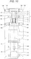
- Figure 10 illustrates an external view of a vacuum switch as Example 4 of the present invention. Dashed lines in Figure 10 show an internal structure. Note that Figure 10 is a plan view of the vacuum switch being installed on or in the railway car. Hence, the longitudinal direction of the vacuum switch is along the longitudinal direction of the railway car. The following description focuses on a point that differs from Example 1.
- the vacuum switch of the present Example 3 has a function as straight joints for connection of a cable (corresponding to the cable 42A in Figure 7 ) that is connected to the bushing conductor 12A and a cable (corresponding to the cable 42B in Figure 7 ) that is connected to the bushing conductor 12B, a function as T-shape joints for branching of a cable (corresponding to the cable 42C in Figure 7 ) that is connected to the bushing conductor 12C in the side of the movable electrode 5a, and a function as T-shape joints for branching of a cable that is connected to a bushing conductor 12D in the fixed side.
- Figure 11 illustrates an external view of a vacuum switch as Example 5 of the present invention. Dashed lines in Figure 11 show an internal structure. Note that Figure 11 is a side view of the vacuum switch being installed on or in the railway car. Note that the longitudinal direction of the vacuum switch is along the longitudinal direction of the railway car. The following description focuses on a point that differs from Example 1.
- the air insulated actuating rod 20 and the electromagnetic actuator 30 are not disposed coaxially and the air insulated actuating rod 20 and the movable side actuating axis of the electromagnetic actuator 30 are placed at different heights from the base 81 in a state when the vacuum switch is installed.
- the air insulated actuating rod 20 and the movable side actuating axis of the electromagnetic actuator 30 are connected via a link 84 as well as the actuating link portion 31. That is, the air insulated actuating rod 20 and the movable side actuating axis of the electromagnetic actuator 30 are coupled non-coaxially via the link 84.
- strokes of the electromagnetic actuator can be made different from strokes of the air insulated actuating rod 20 and the degree of freedom of setting the strokes of both expands. Consequently, workability of stroke adjustment improves.
- the link 84 with a mechanism acting as a lever, it is possible to decrease the output of the electromagnetic actuator 30. Thereby, the electromagnetic actuator 30 can be downsized. Consequently, the electromagnetic actuator 30 can be stored in the mechanics case 82.
- Figure 12 illustrates an external view of a vacuum switch as Example 6 of the present invention. Dashed lines in Figure 12 show an internal structure. Note that Figure 12 is a side view of the vacuum switch installed on the roof of the railway car along the longitudinal direction. The longitudinal direction of the vacuum switch is along the longitudinal direction of the railway car. Also, Figure 12 depicts a state when the T-shape cable heads have been connected to the vacuum switch. The following description focuses on a point that differs from Example 1.
- the base 81 of the vacuum switch is installed on the train roof 86.
- two bushing conductors 12A, 12 D in the side of the fixed conductor 3b and a bushing conductor 12C in the side of the movable conductor 5b are disposed in a direction perpendicular to the longitudinal direction of the vacuum switch and in a direction perpendicular to the plane of the base 81. That is, the bushing conductors 12A, 12C, 12D protrude in a direction perpendicular to the plane on which the vacuum switch is installed. Thereby, the bushing conductor 12A protrudes inside the car under the train roof 86 and the cable that is connected to the bushing conductor 12A can be wired under the train roof 86.
- the vacuum switch can have both straight joint and T branch joint functions.
- a place where the base 81 is installed is not limited to on the train roof 86 as in the present Example 6 and may be, inter alia, under the roof, on the floor, or under the floor of the railway car.
- the bushing conductor 12A is protruded and its cable can be wired in an opposite side to the side where the vacuum switch is located with respect to the base 81. Consequently, the degree of freedom of placing the vacuum switch expands.
- a vacuum switch according to the present invention is applicable to various types of power receiving and power distribution facilities, not limited to railway car application.
- a vacuum switch according to the present invention may be installed such that its longitudinal direction is along a direction perpendicular to a horizontal plane of a site where it is installed.
- PG1, PG2 pantographs, RC1, RC2, RC3, RC4, RC5: high-voltage pull-through cable, SJ1, SJ2, SJ3, SJ4: straight joint, TJ1, TJ2: T branch joint, Tr1, Tr2, Tr3: main transformer, VCB1, VCB2, VCB3: power receiving vacuum circuit breaker, 1: vacuum interrupter, 2: bellows, 3a: fixed electrode, 3b: fixed conductor, 5a: movable electrode, 5b: moveable conductor, 6: arc shield, 7: ceramic insulating cylinder, 8: guide, 10A, 10B, 10C, 10D: connection port, 12, 12A, 12B, 12C, 12D: bushing conductor, 13: conductive shield, 20: air insulated actuating rod, 21: solid insulator, 22: solid insulator inner wall, 23: ground layer, 24: metallic adapter, 25: housing, 26: shaft support, 27: flexible conductor, 30: electromagnetic actuator, 31: actuating
Landscapes
- High-Tension Arc-Extinguishing Switches Without Spraying Means (AREA)
Abstract
Description
- The present invention relates to a solid dielectric vacuum switch.
- A switch that is mounted on or in a railway car is placed on the roof or under the floor of the railway car. Dimensions of the switch, particularly their height and width dimensions are limited in terms of reducing air resistance, height of the car when passing through tunnels, and space restriction on the roof or under the floor among others.
- As a down sizable switch, a solid dielectric vacuum switch is known, as described in
Patent Literature 1 andPatent Literature 2. - A switch described in
Patent Literature 1 includes a vacuum interrupter, a movable actuating shaft, a contact pressure spring mechanism that is disposed near a connection portion between the movable actuating shaft and a movable conductor, and a conductive box surrounding the contact pressure spring mechanism and the vacuum interrupter and the conductive box for relaxing an electric field are molded by an insulator. - In addition, in a switch described in
Patent Literature 2, a ground layer is provided on the outer periphery of an insulation layer that is provided around the vacuum interrupter. -
- Patent Literature 1: Japanese Patent Application Laid-Open No.
2012-69345 - Patent Literature 2: Japanese Patent Application Laid-Open No.
2017-21939 - In the switch described in
Patent Literature 1, because an insulation distance is needed when other components of equipment are placed around the switch, there will be an increase in the space for installing various components of equipment including the switch. - In addition, in the switch described in
Patent Literature 2, an insulation distance to peripheral components of equipment can be reduced because the outer periphery of the insulation layer is grounded. However, no consideration is taken for an insulated actuating rod that is coupled to the movable conductor in the vacuum interrupter, an actuator that is coupled to the insulated actuating rod, and insulation in the periphery of these components. - Accordingly, the present invention provides a solid dielectric vacuum switch enabling it to decrease the insulation distance to peripheral components of equipment and improve the insulation characteristic. Solution to Problem
- To solve problems noted above, a solid dielectric vacuum switch according to the present invention includes a vacuum interrupter having a fixed electrode, a movable electrode, a fixed conductor that is connected to the fixed electrode, and a movable conductor that is connected to the movable electrode; an insulated actuating rod that is mechanically connected to the movable conductor; an actuator that actuates the insulated actuating rod; and a solid insulator covering the vacuum interrupter. A ground layer covering an outer surface of the solid insulator is provided. A conductive shield is provided within the solid insulator, the conductive shield covering around a connection portion between the movable conductor and the insulated actuating rod.
- According to the present invention, it is possible to decrease the insulation distance between a vacuum switch and its peripheral components of equipment and to improve the insulation characteristic of the vacuum switch.
- Problems, configurations, and advantageous effects other than described above will be made apparent from the following description of embodiments.
-
-
Figure 1 illustrates an example of a train set of railway cars on or in which vacuum switches as Example 1 are mounted. -
Figure 2 illustrates feeding circuits of the railway cars inFigure 1 . -
Figure 3 illustrates another example of the train set of railway cars on or in which vacuum switches as Example 1 are mounted. -
Figure 4 illustrates feeding circuits of the railway cars inFigure 3 . -
Figure 5 illustrates an external view of a vacuum switch as Example 1 of the present invention. -
Figure 6 is a cross-sectional view of the vacuum switch of Example 1 when cut along a longitudinal direction. -
Figure 7 illustrates a state in which T-shape cable heads are connected to the vacuum switch of Example 1. -
Figure 8 is a cross-sectional view of a vacuum switch as Example 2 when cut along a longitudinal direction. -
Figure 9 illustrates an external view of a vacuum switch as Example 3. -
Figure 10 illustrates an external view of a vacuum switch as Example 4. -
Figure 11 illustrates an external view of a vacuum switch as Example 5. -
Figure 12 illustrates an external view of a vacuum switch as Example 6. - A vacuum switch as one embodiment of the present invention is a solid dielectric vacuum switch with its surface being covered with a ground potential. The vacuum switch is installed such that its longitudinal direction is parallel to the ground plane, for example, such that the longitudinal direction is along the traveling direction of a railway car at the top of the roof or on the floor of the railway car. Bushings to which cables are connected are disposed in any of upper, lower, left, and right positions in a direction perpendicular to the longitudinal direction. An actuating mechanics case is disposed substantially in line with a vacuum interrupter that is a switch unit. Thereby, it is possible to reduce height and width dimensions of the switch when installed. Also, because the surface is covered with the ground potential, it is possible to decrease the insulation distance between the vacuum switch and its peripheral components of equipment. Consequently, it is possible to reduce the space where the peripheral components of equipment are installed.
- However, according to the study by the present inventors, when the surface of the vacuum switch is covered with the ground potential, a high electric field region is created inside the vacuum switch. Particularly, because the periphery of an insulated actuating rod is covered with atmospheric air where a breakdown electric field is low in comparison with solid insulating resin or the like, insulation performance may deteriorate potentially when a high electric field region is created.
- Therefore, in the vacuum switch as one embodiment of the present invention, a conductive shield covering around the insulated actuating rod is provided and this conductive shield is disposed near to the surface ground layer. Thereby, the electric field in an air space around the insulated actuating rod inside the switch is relaxed and, consequently, the insulation characteristic of the vacuum switch improves. Moreover, according to the study by the present inventors, by these surface ground layer and conductive shield, the effect of relaxing the electric field becomes greater than when only the conductive shield is provided.
- In the following, embodiments of the present invention will be described by Examples 1 to 6 set forth below and with the aid of the drawings. Note that identical reference numerals across the drawings denote identical structural elements or structural elements having a similar function.
- Railway cars on or in which vacuum switches as Example 1 are mounted is first described with
Figures 1 to 4 . -
Figure 1 illustrates an example of a train set of railway cars on or in which vacuum switches as Example 1 are mounted. - The train set illustrated in
Figure 1 is composed of eight cars (1st to 8th cars) . High-voltage pull-through cables RC1, RC2, RC3, RC4, and RC5 are disposed on the roofs of these cars. High-voltage pull-through cables RC3, RC5 are connected to pantographs PG1, PG2, respectively. The railway cars receive electric power from a feeder (not illustrated) and the received electric power is distributed to each car through the high-voltage pull-through cables R1 to R5. - The respective cables are connected by straight joints SJ1, SJ2, SJ3, SJ4 positioned on the roofs between the cars and branched toward a car floor direction by T branch joints TJ1, TJ2 on the roofs. Here, a T branch joint TJ1 and a straight joint SJ2 are integrated into a vacuum switch which will be described later and a T branch joint TJ2 and a straight joint SJ4 are also integrated into a vacuum switch.
-
Figure 2 illustrates a feeder (feeding) circuit of the railway cars inFigure 1 . - As shown in
Figure 2 , under the floors (Under Floor) of the second car (2nd car), fourth car (4th car), and sixth car (6th car), power receiving vacuum circuit breakers VCB1, VCB2, VCB3 are provided respectively and, in addition, main transformers Tr1, Tr2, Tr3 are provided respectively. - A high-voltage pull-through cable RC1 of the 2nd car is directly connected to a primary side of a power receiving vacuum circuit breaker VCB1 and a secondary side of the power receiving vacuum circuit breaker VCB1 is connected to a primary winding of a main transformer Tr1. A secondary winding of the main transformer Tr1 supplies power to an electric motor and its tertiary winding supplies power to auxiliary equipment such as air-conditioners and illumination.
- High-voltage pull-through cables that are branched by T branch joints TJ1, TJ2 of the fourth car (4th car) and sixth car (6th car) are respectively connected to the primary sides of power receiving vacuum circuit breakers VCB2, VCB3 provided under the floors. The secondary sides of the power receiving vacuum circuit breakers VCB2, VCB3 are respectively connected to the primary windings of main transformers Tr2, Tr3. The secondary windings of the main transformers Tr2, Tr3 supply power to electric motors and their tertiary windings supply power to the auxiliary equipment.
- Note that power may be supplied to the electric motors and auxiliary equipment via a power converter from the main transformers.
- As described above, the power receiving vacuum circuit breakers VCB1, VCB2, VCB3 and the main transformers Tr1, Tr2, Tr3 are disposed under the floors and other components of electric equipment (RC1 to 5, SJ1 to 4, PG1 to 2, TJ1 to 2) are disposed on the roofs. Because VCB1 to 3 and Tr1 to 3 are disposed under the floors, work on the roofs for installing, maintaining, and inspecting components of electrical equipment is reduced. Also, when components of electrical equipment are disposed on the roofs, space in a height direction is much restricted. Nevertheless, as will be described later, the dimension of a vacuum switch in a height direction can be decreased according to Example 1 of the present invention and, therefore, the vacuum switch can be installed easily on the roofs.
-
Figure 3 illustrates another example of the train set of the railway cars on or in which vacuum switches as Example 1 are mounted. In addition,Figure 4 illustrates a feeding circuit in the railway cars inFigure 3 . - As shown in
Figure 3 and Figure 4 , in the present Example, the high-voltage pull-through cables RC1 to 5, straight joints SJ1 to 4, and T branch joints TJ1 to 2 are installed under the floors (Under Floor). In addition, some high-voltage cables are led inside the cars from the pantographs PG1, PG2 and connected to the high-voltage pull-through cables RC3, RC5, respectively. When components of electrical equipment are installed under the floors in this way, installation space is much restricted. Nevertheless, a vacuum switch can be installed easily under the floors according to Example 1 that will be described later. - As shown in
Figure 2 andFigure 4 , in a case where a line-to-ground fault (Fault) has occurred at the high-voltage pull-through cable RC2 in the third car (3rd car), a vacuum switch is operated by a command from outside to open the straight joint SJ2 automatically, thereby disconnecting the main transformer Tr1 and an electric motor connected thereto that are affected by the line-to-ground fault (Fault) from the feeding circuit. At this time, the main transformers Tr2, Tr3 that are not affected by the line-to-ground fault (Fault) remain connected to the feeding circuit and, therefore, operation of the railway cars can be continued using electric motors that are connected to these transformers. - Note that a vacuum switch to be operated, i.e., a straight joint (SJ2 or SJ4) to be disconnected is selected appropriately depending on the location of the line-to-ground fault. Thereby, it is possible to' separate high-voltage cables that are healthy from a high-voltage cable including the fault location automatically.
- Then, a vacuum switch as Example 1 of the present invention is described with
Figures 5 to 7 . Note that a vacuum switch of the present Example 1 is integrated with a T branch joint (TJ1 or TJ2) and a straight joint (SJ2 or SJ4) in a case where it is mounted on or in the railway car. -
Figure 5 illustrates an external view of a vacuum switch as Example 1 of the present invention. Dashed lines inFigure 5 show an internal structure. Note thatFigure 5 is a plan view of the vacuum switch being installed on or in the railway car (the same is also true forFigures 6 and7 ). Therefore, a longitudinal direction of the vacuum switch is along a longitudinal direction of the railway car. - As shown in
Figure 5 , the vacuum switch of the present Example 1 is mounted on or in the railway car with the vacuum switch being set stationary on abase 81 viastays 83A to 83C. -
Figure 6 is a cross-sectional view of the vacuum switch of Example 1 when cut along the longitudinal direction. Note that the cutting plane is a plane including the central axis of amovable electrode 5a and an air insulatedactuating rod 20 which will be described later. - As shown in
Figure 6 , the vacuum switch of Example 1 includes avacuum interrupter 1 comprising a fixedelectrode 3a, amovable electrode 5a that comes in or out of contact with the fixedelectrode 3a, anarc shield 6 that covers surrounding of the fixedelectrode 3a and themovable electrode 5a, a ceramic insulatingcylinder 7 having a cylindrical form and forming a part of an outer container that supports thearc shield 6, and abellows 2, as main parts. - The outer container of the
vacuum interrupter 1 is comprised of the ceramic insulatingcylinder 7 and end plates covering both ends of the ceramic insulatingcylinder 7, and its inside is maintained in a vacuum state. The fixedelectrode 3a is connected to a fixedconductor 3b and the fixedconductor 3b is extended outside thevacuum interrupter 1 and electrically connected to abushing conductor 12A adjacent to the fixedconductor 3b. Themovable electrode 5a is connected to amovable conductor 5b and themovable conductor 5b is extended outside thevacuum interrupter 1 and electrically connected to bushingconductors movable conductor 5b. - The
vacuum interrupter 1, thebushing conductor 12A adjacent to the fixedconductor 3b, and thebushing conductors movable conductor 5b are molded and coated with asolid insulator 21 made of epoxy resin or the like. In addition, the surface of thesolid insulator 21 is covered with aground layer 23. Ground potential is given to theground layer 23. Note that theground layer 23 is formed by metallic spraying or applying a conductive coating material among others. The outermost ends of the respective bushing conductors toward external air are not molded with thesolid insulator 21 and a conductor portion is exposed. These outermost ends make upconnection ports Figure 7 ). - In a movable side of the
vacuum interrupter 1, thebellows 2 is disposed between themovable conductor 5b and the movable-side end plate. This bellows allows themovable conductor 5b to move, while maintaining the vacuum state of thevacuum interrupter 1. Also, in the movable side of thevacuum interrupter 1, anelectromagnetic actuator 30 that actuates an air insulatedactuating rod 20 is provided. A movable side actuating axis of theelectromagnetic actuator 30 is coaxially connected to the air insulatedactuating rod 20 via anactuating link portion 31. Theelectromagnetic actuator 30, theactuating link portion 31, and an end portion of the air insulatedactuating rod 20 connected to theelectromagnetic actuator 30 are stored in amechanics case 82 that coaxially contacts a substantially cylindrical mold part made by thesolid insulator 21. Therefore, in the vacuum switch, theelectromagnetic actuator 30 is disposed coaxially with the air insulatedactuating rod 20. - In the
electromagnetic actuator 30, for example, using a device combining a permanent magnet and an electromagnet with a spring, by turning ON/OFF electric conduction to a coil forming an electromagnet, a drive force is generated. Note that the structure of theelectromagnetic actuator 30 in the present Example is publicly known and detailed description of theelectromagnetic actuator 30 is omitted. - Using the
electromagnetic actuator 30, by actuating a drive axis of themovable electrode 5a, provided by coupling the air insulatedactuating rod 20 and themovable conductor 5b integrally and coaxially with ametallic adapter 24, it is possible to make themovable electrode 5a come in or out of contact with the fixedelectrode 3a while ensuring a sufficient insulation distance between thevacuum interrupter 1 and theelectromagnetic actuator 30. Moreover, between themovable conductor 5b and thebushing conductors metallic adapter 24 and aflexible conductor 27 that electrically connects themetallic adapter 24 and the bushing conductors, moving with themovable conductor 5b; thereby, conductivity and movability are ensured. - Furthermore, in the present Example 1, as shown in
Figure 6 , within thesolid insulator 21, aconductive shield 13 is provided to cover the outer periphery of a connection portion between an end portion of the air insulatedactuating rod 20 toward themovable conductor 5b and themovable conductor 5b. Theconductive shield 13 is electrically connected with themovable conductor 5b via thebushing conductors flexible conductor 27. Also, an end portion of theconductive shield 13 toward themovable conductor 5b is in contact with and electrically connected with thebushing conductors movable conductor 5b. - Within the
solid insulator 21, theconductive shield 13 extends from a portion where it contacts thebushing conductors movable conductor 5b toward a direction of theelectromagnetic actuator 30. Thereby, theconductive shield 13 covers the periphery of themetallic adapter 24, ahousing 25, and ashaft support 26, and theflexible conductor 27, existing around the connection portion between the air insulatedactuating rod 20 and themovable conductor 5b, that is, the periphery of conductor portions around the connection portion between the air insulatedactuating rod 20 and themovable conductor 5b and, in addition, the periphery of an air-exposed part of the air insulatedactuating rod 20 extending from a connection portion with themetallic adapter 24 toward the direction of theelectromagnetic actuator 30. - Additionally, the
conductive shield 13 is made of a conductive material such as metal and conductive rubber. - By this
conductive shield 13 and theabovementioned ground layer 23, when high voltage is applied to theconductive shield 13 via thebushing conductors solid insulator 21 between theconductive shield 13 and theground layer 23 and electric field concentration is relaxed in the air surrounding the conductor portions around the connection portion between the air insulatedactuating rod 20 and themovable conductor 5b. Moreover, a region where the electric field is concentrated between theconductive shield 13 and theground layer 23 and in an end portion of theconductive shield 13 toward theelectromagnetic actuator 30 is covered with thesolid insulator 21 having higher dielectric strength than air. Owing to those above, the insulation characteristic of the vacuum switch improves even with provision of theground layer 23. Therefore, according to the present Example 1, a decrease in insulation distance to peripheral components of equipment is enabled and the insulation characteristic of the vacuum switch improves. - Note that, because the solid insulator
inner wall 22 near an end portion of theconductive shield 13 contacts air, insulation may be weakened potentially in this portion. Therefore, in the present Example 1, a thickness b of thesolid insulator 21 between the solid insulatorinner wall 22 and theconductive shield 13 is made larger than a thickness a of thesolid insulator 21 between theground layer 23 and the conductive shield 13 (b > a), as indicated in section A circled with a dashed line inFigure 6 . Thereby, within thesolid insulator 21, theconductive shield 13 is disposed nearer to the outer surface of thesolid insulator 21, i.e., theground layer 23 than the solid insulatorinner wall 22. That is, within thesolid insulator 21, theconductive shield 13 is disposed far from the solid insulatorinner wall 22 or close to the outer surface of thesolid insulator 21 and there can be an increase in the thickness of thesolid insulator 21 between the solid insulatorinner wall 22 and theconductive shield 13. Consequently, field strength at the solid insulatorinner wall 22 can be decreased. Note that the thickness a is set to a dimension to adjust the field strength so that an electric field between theconductive shield 13 and theground layer 23 does not cause deterioration in insulation of thesolid insulator 21. - In addition, in the present Example 1, the end portion of the
conductive shield 13 toward theelectromagnetic actuator 30 bends toward theground layer 23 within thesolid insulator 21. This makes the above end portion farther from its adjacent solid insulatorinner wall 22 and, consequently, electric field concentration can be relaxed at the solid insulatorinner wall 22 where electric field concentration is liable to occur. - Moreover, the solid insulator
inner wall 22 adjacent to the end portion of theconductive shield 13 has a convex curved inner wall surface facing an air space in the vacuum switch. More specifically, the solid insulatorinner wall 22 has a first cylindrical inner wall surface with an inner diameter being substantially constant for a section from a portion adjacent to the connection portion between the air insulatedactuating rod 20 and themovable conductor 5b to a portion adjacent to the end portion of theconductive shield 13, has the convex curved surface facing the air space for a section adjacent to the end portion of theconductive shield 13, and has a second cylindrical inner wall surface with an inner diameter being substantially constant and larger than the first inner wall surface for a section extending toward theelectromagnetic actuator 30 from the portion adjacent to the end portion of theconductive shield 13. These first inner wall surface, convex curved inner wall surface facing the air space, and second inner wall surface form a smoothly continuing surface. - Additionally, the entire thickness of the
solid insulator 21 abutting the first inner wall surface and the entire thickness of the solid insulator abutting the second inner wall surface are approximately equal; for example, the insulator thickness is set to a thickness that is the sum of thickness dimensions a and b in section A inFigure 6 plus the thickness of theconductive shield 13 or a thickness that is the sum of thickness dimensions a and b. Thereby, the mechanical strength and insulation performance of the vacuum switch improve. - Additionally, in the present Example 1, in conjunction with the setting of the entire thickness of the
solid insulator 21, the outer surface that contacts external air of thesolid insulator 21, i.e., the outer surface of theground layer 23 has a first cylindrical outer surface with an outer diameter being substantially constant for a section from the portion adjacent to the connection portion between the air insulatedactuating rod 20 and themovable conductor 5b to the portion adjacent to the end portion of the conductive shield, a convex curved surface facing the external air for a section adjacent to the end portion of theconductive shield 13, and has a second cylindrical outer surface with an outer diameter being substantially constant and larger than the first outer surface for a section extending toward theelectromagnetic actuator 30 from the portion adjacent to the end portion of theconductive shield 13. These first outer surface, convex curbed outer surface facing the external air, second outer surface form a smoothly continuing surface. That is, the shape of the outer surface of thesolid insulator 21 and theground layer 23 is similar to the shape of the inner wall surface of thesolid insulator 21. - By of the above-described shape of the solid insulator inner wall and owing to the fact that this shape allows for an increase in the thickness of the
solid insulator 21 between the solid insulatorinner wall 22 and theconductive shield 13 in a portion adjacent to the end portion of theconductive shield 13 toward theelectromagnetic actuator 30, it is possible to relax electric field concentration at the solid insulatorinner wall 22 adjacent to the end portion of the conductive shield. - Additionally, as described previously, by setting thickness dimensions a and b of the
solid insulator 21 to be a < b, as indicated in section A inFigure 6 , so that the conductive shield is disposed nearer to the outer surface of thesolid insulator 21, heat radiation performance of the vacuum switch improves. - As shown in
Figure 6 , in the vacuum switch of the present Example 1, aguide 8 and ashaft support 26 are provided to restrict the direction of movement of the drive axis of themovable electrode 5a and enhance smoothness of a sliding motion; themovable electrode 5a,movable conductor 5b,metallic adapter 24, and air insulatedactuating rod 20 are coaxially assembled on the above drive axis. Theguide 8 supports a shaft of themovable conductor 5b that is constituent of the drive axis of themovable electrode 5a. Also, theshaft support 26 that is held in thehousing 25 supports a shaft of themetallic adapter 24 that is constituent of the drive axis of themovable electrode 5a. In this way, the support of shaft is provided by two components which are theguide 8 and thesupport shaft 26. This improves the accuracy of centering of themovable conductor 5b,metallic adapter 24, and air insulatedactuating rod 20 that are assembled coaxially and, consequently, smoothness of the sliding motion improves. Note that, in the present Example 1, theguide 8 and theshaft support 26 have a shape in which a flange is placed on one end of a short tube; however, they may have another shape, not limited to this shape. - In the present Example 1, inside the vacuum switch, a space surrounding the air insulated
actuating rod 20 and a space surrounding the connection portion between the air insulatedactuating rod 20 and themovable conductor 5b are filled with air and ambient gas is atmospheric air; however, there is no limitation to this and such space may be filled with insulating gas such as dry air and SF6 gas. This contributes to improvement in the insulation performance of the vacuum switch. Additionally, in this case, using sealing means such as a sealant, sealing is provided between the opening of thesolid insulator 21 toward theelectromagnetic actuator 30 and the opening of themechanics case 82 abutting the solid insulator to keep in insulating gas inside the vacuum switch. -
Figure 7 illustrates a state in which T-shape cable heads 40A, 40B, 40C are connected to the vacuum switch of the present Example 1. - Conductor portions inside the T-shape cable heads 40A, 40B, 40C that are respectively connected with the end portions of
cables bushing conductors - As shown in
Figure 7 , in the vacuum switch of the present Example 1, thevacuum interrupter 1, air insulatedactuating rod 20, andelectromagnetic actuator 30 are disposed coaxially and substantially in line. In addition, thebushing conductors movable electrode 5a,movable conductor 5b, and air insulatedactuating rod 20 moves and in a direction parallel to the plane on which the vacuum switch is set stationary on thebase 81. Thereby, with the cables connected to the vacuum switch, theelectromagnetic actuator 30 and the T-shape cable heads 40A, 40B, 40C do not interfere with each other and it is possible to decrease the height and width dimensions of the vacuum switch after cable connection. - As described previously, according to the present Example 1, the surface of the
solid insulator 21 that molds the constituent parts of the vacuum switch is covered with theground layer 23 and theconductive shield 13 is provided within the solid insulator to cover around the connection portion between the air insulatedactuating rod 20 and themovable conductor 5b; thereby, the insulation performance of the vacuum switch can be improved even with provision of theground layer 23. In addition, because it is possible to decrease the height and width dimensions of the vacuum switch after cable connection, it is possible to increase the degree of freedom of a location where the vacuum switch is installed on or in the railway cars or the like. In addition, owing to the fact that the surface of the vacuum switch is covered with theground layer 23, it is possible to decrease the insulation distance between the vacuum switch and its peripheral components of equipment, and therefore, it is possible to decrease the entire space for installing the vacuum switch together with its peripheral components of equipment. -
Figure 8 is a cross-sectional view of a vacuum switch as Example 2 of the present invention when cut along the longitudinal direction. The following description focuses on a point that differs from Example 1. - First, in the case of the present Example 2, as with Example 1, the solid insulator
inner wall 22 has a first cylindrical inner wall surface with an inner diameter being substantially constant for a section from a portion adjacent to the connection portion between the air insulatedactuating rod 20 and themovable conductor 5b to a portion adjacent to the end portion of theconductive shield 13, has a convex curved surface facing the air space for a section adjacent to the end portion of theconductive shield 13, and has a second cylindrical inner wall surface with an inner diameter being substantially constant and larger than the first inner wall surface for a section extending toward theelectromagnetic actuator 30 from the portion adjacent to the end portion of theconductive shield 13. These first inner wall surface, convex curved inner wall surface facing the air space, and second inner wall surface form a smoothly continuing surface. - In the present Example 2, unlike Example 1, the entire thickness of the
solid insulator 21 abutting the second inner wall surface is smaller than the entire thickness of thesolid insulator 21 abutting the first inner wall surface. That is, the entire thickness of thesolid insulator 21 abutting the second inner wall surface is, for example, set to a thickness that is smaller than a thickness that is the sum of thickness dimensions a and b in section A inFigure 6 plus the thickness of theconductive shield 13 or a thickness that is the sum of thickness dimensions a and b. - That is, in the present Example 2, in the
solid insulator 21, the thickness of thesolid insulator 21 is decreased for a section going far from a section adjacent to the end portion of theconductive shield 13, where an electric field easily concentrates, toward theelectromagnetic actuator 30, in other words, a section where field strength becomes lower than that in the section adjacent to the end portion of theconductive shield 13. Thereby, the weight of thesolid insulator 21 is decreased without affecting the insulation performance of the vacuum switch, and consequently, it is possible to make the vacuum switch lighter. -
Figure 9 illustrates an external view of a vacuum switch as Example 3 of the present invention. Dashed lines inFigure 9 show an internal structure. Note thatFigure 9 is a plan view of the vacuum switch being installed on or in the railway car. Hence, the longitudinal direction of the vacuum switch is along the longitudinal direction of the railway car. The following description focuses on a point that differs from Example 1. - In the present Example 3, unlike Example 1, only one
bushing conductor 12B is provided adjacently to themovable conductor 5b. That is, in respect of functions as straight joints and T-shape joints, the vacuum switch of the present Example 3 only has a function as straight joints for connection of a cable (corresponding to thecable 42A inFigure 7 ) that is connected to thebushing conductor 12A and a cable (corresponding to thecable 42B inFigure 7 ) that is connected to thebushing conductor 12B. - According to the present Example 3, in a case where there are a location where a cable branch is present and a location where a cable branch is not present, as in the railway car, it is possible to improve the insulation performance of the vacuum switch integrated with a straight joint in the location where a cable branch is not present and to decrease the insulation distance between the vacuum switch and its peripheral components of equipment. In addition, it is possible to decrease the height and width dimensions of the vacuum switch after cable connection.
-
Figure 10 illustrates an external view of a vacuum switch as Example 4 of the present invention. Dashed lines inFigure 10 show an internal structure. Note thatFigure 10 is a plan view of the vacuum switch being installed on or in the railway car. Hence, the longitudinal direction of the vacuum switch is along the longitudinal direction of the railway car. The following description focuses on a point that differs from Example 1. - In the present Example 4, as with Example 1, two bushing
conductors movable electrode 5a; whereas, unlike Example 1, twobushing conductor electrode 3a. Thereby, the vacuum switch of the present Example 3 has a function as straight joints for connection of a cable (corresponding to thecable 42A inFigure 7 ) that is connected to thebushing conductor 12A and a cable (corresponding to thecable 42B inFigure 7 ) that is connected to thebushing conductor 12B, a function as T-shape joints for branching of a cable (corresponding to thecable 42C inFigure 7 ) that is connected to thebushing conductor 12C in the side of themovable electrode 5a, and a function as T-shape joints for branching of a cable that is connected to abushing conductor 12D in the fixed side. - In the present Example, because cable branching is enabled also in the side of the fixed
electrode 3a in addition to the side of themovable electrode 5a, it is possible to expand the degree of freedom of circuit configurations of the feeder circuit. -
Figure 11 illustrates an external view of a vacuum switch as Example 5 of the present invention. Dashed lines inFigure 11 show an internal structure. Note thatFigure 11 is a side view of the vacuum switch being installed on or in the railway car. Note that the longitudinal direction of the vacuum switch is along the longitudinal direction of the railway car. The following description focuses on a point that differs from Example 1. - In the present Example 5, as shown in
Fig. 11 , the air insulatedactuating rod 20 and theelectromagnetic actuator 30 are not disposed coaxially and the air insulatedactuating rod 20 and the movable side actuating axis of theelectromagnetic actuator 30 are placed at different heights from the base 81 in a state when the vacuum switch is installed. The air insulatedactuating rod 20 and the movable side actuating axis of theelectromagnetic actuator 30 are connected via alink 84 as well as theactuating link portion 31. That is, the air insulatedactuating rod 20 and the movable side actuating axis of theelectromagnetic actuator 30 are coupled non-coaxially via thelink 84. Thereby, strokes of the electromagnetic actuator can be made different from strokes of the air insulatedactuating rod 20 and the degree of freedom of setting the strokes of both expands. Consequently, workability of stroke adjustment improves. In addition, by providing thelink 84 with a mechanism acting as a lever, it is possible to decrease the output of theelectromagnetic actuator 30. Thereby, theelectromagnetic actuator 30 can be downsized. Consequently, theelectromagnetic actuator 30 can be stored in themechanics case 82. -
Figure 12 illustrates an external view of a vacuum switch as Example 6 of the present invention. Dashed lines inFigure 12 show an internal structure. Note thatFigure 12 is a side view of the vacuum switch installed on the roof of the railway car along the longitudinal direction. The longitudinal direction of the vacuum switch is along the longitudinal direction of the railway car. Also,Figure 12 depicts a state when the T-shape cable heads have been connected to the vacuum switch. The following description focuses on a point that differs from Example 1. - As shown in
Figure 12 , in the present Example 6, thebase 81 of the vacuum switch is installed on thetrain roof 86. In addition, twobushing conductors conductor 3b and abushing conductor 12C in the side of themovable conductor 5b are disposed in a direction perpendicular to the longitudinal direction of the vacuum switch and in a direction perpendicular to the plane of thebase 81. That is, thebushing conductors bushing conductor 12A protrudes inside the car under thetrain roof 86 and the cable that is connected to thebushing conductor 12A can be wired under thetrain roof 86. - Note that, even by organizing the bushing conductors as in the present Example 6 (two in the fixed conductor side and one in the movable conductor side) (one in the fixed conductor side and two in the movable conductor side in Example 1), the vacuum switch can have both straight joint and T branch joint functions.
- Note that a place where the
base 81 is installed is not limited to on thetrain roof 86 as in the present Example 6 and may be, inter alia, under the roof, on the floor, or under the floor of the railway car. In each case, thebushing conductor 12A is protruded and its cable can be wired in an opposite side to the side where the vacuum switch is located with respect to thebase 81. Consequently, the degree of freedom of placing the vacuum switch expands. - Now, the present invention is not limited to Examples described hereinbefore and various modifications are included therein. For example, the foregoing Examples are those described in detail to explain the present invention clearly and the invention is not necessarily limited to those including all components described. In addition, for a subset of the components of each Example, other components may be added to the subset or the subset may be removed or replaced by other components.
- For instance, a vacuum switch according to the present invention is applicable to various types of power receiving and power distribution facilities, not limited to railway car application. In addition, a vacuum switch according to the present invention may be installed such that its longitudinal direction is along a direction perpendicular to a horizontal plane of a site where it is installed.
- PG1, PG2: pantographs, RC1, RC2, RC3, RC4, RC5: high-voltage pull-through cable, SJ1, SJ2, SJ3, SJ4: straight joint, TJ1, TJ2: T branch joint, Tr1, Tr2, Tr3: main transformer, VCB1, VCB2, VCB3: power receiving vacuum circuit breaker, 1: vacuum interrupter, 2: bellows, 3a: fixed electrode, 3b: fixed conductor, 5a: movable electrode, 5b: moveable conductor, 6: arc shield, 7: ceramic insulating cylinder, 8: guide, 10A, 10B, 10C, 10D: connection port, 12, 12A, 12B, 12C, 12D: bushing conductor, 13: conductive shield, 20: air insulated actuating rod, 21: solid insulator, 22: solid insulator inner wall, 23: ground layer, 24: metallic adapter, 25: housing, 26: shaft support, 27: flexible conductor, 30: electromagnetic actuator, 31: actuating link portion, 40A, 40B, 40C, 40D: T-shape cable head, 41A, 41B, 41C, 41D: insulation plug, 42A, 42B, 42C, 42D: cable, 81: base, 82: mechanics case, 83A, 83B, 83C: stay, 84: link, 86: train roof
Claims (14)
- A solid dielectric vacuum switch comprising:a vacuum interrupter having a fixed electrode, a movable electrode, a fixed conductor that is connected to the fixed electrode, and a movable conductor that is connected to the movable electrode;an insulated actuating rod that is mechanically connected to the movable conductor;an actuator that actuates the insulated actuating rod; anda solid insulator covering the vacuum interrupter, wherein a ground layer covering an outer surface of the solid insulator is provided; anda conductive shield is provided within the solid insulator, the conductive shield covering around a connection portion between the movable conductor and the insulated actuating rod.
- The solid dielectric vacuum switch according to claim 1,
wherein the conductive shield is disposed nearer to the ground layer than an inner wall of the solid insulator. - The solid dielectric vacuum switch according to claim 1,
wherein a thickness of the solid insulator between an inner wall of the solid insulator and the conductive shield is larger than a thickness of the solid insulator between the ground layer and the conductive shield. - The solid dielectric vacuum switch according to any one of claims 1 to 3,
wherein an end portion of the conductive shield bends toward the ground layer. - The solid dielectric vacuum switch according to any one of claims 1 to 3,
wherein an inner wall surface of the solid insulator adjacent to an end portion of the conductive shield has a convex curved surface facing an air space. - The solid dielectric vacuum switch according to claim 1,
wherein a thickness of the solid insulator for a section between the end portion of the conductive shield and the actuator is smaller than a thickness of the solid insulator for a section between the connection portion between the movable conductor and the insulated actuating rod and the end portion of the conductive shield, wherein these sections are contiguous. - The solid dielectric vacuum switch according to claim 1, comprising:a first bushing conductor that is connected to the fixed conductor; anda second bushing conductor that is connected to the movable conductor,wherein the first bushing conductor and the second bushing conductor are covered with the solid insulator.
- The solid dielectric vacuum switch according to claim 7, comprising a third bushing conductor that is connected to the fixed conductor or the movable conductor,
wherein the third bushing conductor is covered with the solid insulator. - The solid dielectric vacuum switch according to claim 1, comprising a plurality of bushing conductors, each of which is connected to one of the fixed conductor and the movable conductor,
wherein the plurality of bushing conductors are covered with the solid insulator; and
the plurality of bushing conductors are disposed in a direction perpendicular to a movable direction of the movable electrode, the movable conductor, and the insulated actuating rod. - The solid dielectric vacuum switch according to claim 9,
wherein the movable electrode, the movable conductor, and the insulated actuating rod are coupled coaxially. - The solid dielectric vacuum switch according to claim 1, comprising a plurality of bushing conductors, each of which is connected to one of the fixed conductor and the movable conductor,
wherein the plurality of bushing conductors are covered with the solid insulator; and
the plurality of bushing conductors protrude in a direction parallel to a plane on which the vacuum switch is installed. - The solid dielectric vacuum switch according to claim 1, comprising a plurality of bushing conductors, each of which is connected to one of the fixed conductor and the movable conductor,
wherein the plurality of bushing conductors are covered with the solid insulator; and
the plurality of bushing conductors protrude in a direction perpendicular to a plane on which the vacuum switch is installed. - The solid dielectric vacuum switch according to claim 1,
wherein the insulated actuating rod and a movable side actuating axis of the actuator are coupled coaxially. - The solid dielectric vacuum switch according to claim 1,
wherein the insulated actuating rod and a movable side actuating axis of the actuator are coupled non-coaxially via a link portion.
Applications Claiming Priority (2)
| Application Number | Priority Date | Filing Date | Title |
|---|---|---|---|
| JP2018050985A JP6933598B2 (en) | 2018-03-19 | 2018-03-19 | Solid insulation type vacuum switch |
| PCT/JP2019/004839 WO2019181271A1 (en) | 2018-03-19 | 2019-02-12 | Solid dielectric vacuum switchgear |
Publications (3)
| Publication Number | Publication Date |
|---|---|
| EP3770938A1 true EP3770938A1 (en) | 2021-01-27 |
| EP3770938A4 EP3770938A4 (en) | 2022-03-09 |
| EP3770938B1 EP3770938B1 (en) | 2025-08-20 |
Family
ID=67987017
Family Applications (1)
| Application Number | Title | Priority Date | Filing Date |
|---|---|---|---|
| EP19770731.8A Active EP3770938B1 (en) | 2018-03-19 | 2019-02-12 | Solid dielectric vacuum switchgear |
Country Status (4)
| Country | Link |
|---|---|
| EP (1) | EP3770938B1 (en) |
| JP (1) | JP6933598B2 (en) |
| CN (1) | CN111837213B (en) |
| WO (1) | WO2019181271A1 (en) |
Family Cites Families (17)
| Publication number | Priority date | Publication date | Assignee | Title |
|---|---|---|---|---|
| DD241810A1 (en) * | 1985-10-16 | 1986-12-24 | Buchwitz Otto Starkstrom | SWITCHPOL FOR CIRCUIT BREAKER |
| US6373015B1 (en) * | 2000-01-03 | 2002-04-16 | Eaton Corporation | Integral load connector module |
| JP4074068B2 (en) * | 2001-04-19 | 2008-04-09 | 株式会社東芝 | Switchgear |
| JP2003111225A (en) * | 2001-10-02 | 2003-04-11 | Toshiba Corp | Switchgear |
| KR20050110064A (en) * | 2004-05-17 | 2005-11-22 | 주식회사 비츠로테크 | Embeded vacuum interrupter in epoxy barrier for vacuum circuit breaker |
| CN101859662A (en) * | 2010-06-28 | 2010-10-13 | 郑文秀 | Cross full-shielded vacuum circuit breaker |
| JP5565236B2 (en) | 2010-09-22 | 2014-08-06 | 日新電機株式会社 | Vacuum circuit breaker and switchgear |
| JP5183831B2 (en) * | 2010-11-12 | 2013-04-17 | 三菱電機株式会社 | Gas insulated switchgear |
| JP5452555B2 (en) * | 2011-08-29 | 2014-03-26 | 株式会社日立製作所 | Switchgear and switchgear operating method |
| CN102882149B (en) * | 2012-09-07 | 2015-12-23 | 北海银河开关设备有限公司 | Solid insulation pole moved end screening arrangement |
| JP6328998B2 (en) * | 2014-05-22 | 2018-05-23 | 株式会社日立産機システム | Unit switch, switchgear, and railway vehicle |
| CN104201042A (en) * | 2014-09-04 | 2014-12-10 | 麦克奥迪(厦门)电气股份有限公司 | Polar column inner chamber shielding structure of solid insulation switch |
| CN104269316B (en) * | 2014-09-10 | 2018-03-02 | 平高集团有限公司 | Pole and the solid insulation ring main unit using the pole |
| JP6382069B2 (en) * | 2014-10-30 | 2018-08-29 | 株式会社日立産機システム | Switchgear |
| JP2016219175A (en) * | 2015-05-18 | 2016-12-22 | 株式会社東芝 | Resin molded vacuum valve and manufacturing method |
| JP6716209B2 (en) | 2015-07-08 | 2020-07-01 | 株式会社東芝 | Epoxy resin insulation vacuum valve |
| CN106128850A (en) * | 2016-08-24 | 2016-11-16 | 厦门普力维电气科技有限公司 | A kind of outdoor high-voltage pole or automatic circuit |
-
2018
- 2018-03-19 JP JP2018050985A patent/JP6933598B2/en active Active
-
2019
- 2019-02-12 EP EP19770731.8A patent/EP3770938B1/en active Active
- 2019-02-12 CN CN201980017184.3A patent/CN111837213B/en active Active
- 2019-02-12 WO PCT/JP2019/004839 patent/WO2019181271A1/en not_active Ceased
Also Published As
| Publication number | Publication date |
|---|---|
| CN111837213B (en) | 2022-08-26 |
| WO2019181271A1 (en) | 2019-09-26 |
| JP2019164900A (en) | 2019-09-26 |
| JP6933598B2 (en) | 2021-09-08 |
| EP3770938B1 (en) | 2025-08-20 |
| CN111837213A (en) | 2020-10-27 |
| EP3770938A4 (en) | 2022-03-09 |
Similar Documents
| Publication | Publication Date | Title |
|---|---|---|
| US8710388B2 (en) | Switchgear and method for operating switchgear | |
| KR101010295B1 (en) | Vacuum switchgear | |
| US8035054B2 (en) | Vacuum insulated switchgear | |
| KR20100054737A (en) | Vacuum switch gear | |
| EP3125262B1 (en) | Hybrid switching device | |
| EP3147924B1 (en) | Unit switch, switching device, and railroad car | |
| EP3770938B1 (en) | Solid dielectric vacuum switchgear | |
| JP6778129B2 (en) | Switch unit for railroad vehicles | |
| JP6713940B2 (en) | Radiator for solid insulated switchgear unit, solid insulated switchgear unit, and railway vehicle | |
| US10589760B2 (en) | Branching unit and vehicular system | |
| JP6783720B2 (en) | Vacuum switchgear | |
| EP3300096A1 (en) | Switch unit and rail car using the same | |
| US20060245128A1 (en) | Gas-insulated bus bar component comprising outdoor bushings | |
| JP6951201B2 (en) | Switch unit and railroad vehicle using it | |
| US11688566B2 (en) | Switching apparatus for electric systems | |
| EP4456107A1 (en) | Switch |
Legal Events
| Date | Code | Title | Description |
|---|---|---|---|
| STAA | Information on the status of an ep patent application or granted ep patent |
Free format text: STATUS: THE INTERNATIONAL PUBLICATION HAS BEEN MADE |
|
| PUAI | Public reference made under article 153(3) epc to a published international application that has entered the european phase |
Free format text: ORIGINAL CODE: 0009012 |
|
| STAA | Information on the status of an ep patent application or granted ep patent |
Free format text: STATUS: REQUEST FOR EXAMINATION WAS MADE |
|
| 17P | Request for examination filed |
Effective date: 20201019 |
|
| AK | Designated contracting states |
Kind code of ref document: A1 Designated state(s): AL AT BE BG CH CY CZ DE DK EE ES FI FR GB GR HR HU IE IS IT LI LT LU LV MC MK MT NL NO PL PT RO RS SE SI SK SM TR |
|
| AX | Request for extension of the european patent |
Extension state: BA ME |
|
| DAV | Request for validation of the european patent (deleted) | ||
| DAX | Request for extension of the european patent (deleted) | ||
| A4 | Supplementary search report drawn up and despatched |
Effective date: 20220208 |
|
| RIC1 | Information provided on ipc code assigned before grant |
Ipc: H01H 33/66 20060101ALI20220202BHEP Ipc: H01H 33/662 20060101AFI20220202BHEP |
|
| STAA | Information on the status of an ep patent application or granted ep patent |
Free format text: STATUS: EXAMINATION IS IN PROGRESS |
|
| 17Q | First examination report despatched |
Effective date: 20231019 |
|
| GRAP | Despatch of communication of intention to grant a patent |
Free format text: ORIGINAL CODE: EPIDOSNIGR1 |
|
| STAA | Information on the status of an ep patent application or granted ep patent |
Free format text: STATUS: GRANT OF PATENT IS INTENDED |
|
| INTG | Intention to grant announced |
Effective date: 20250507 |
|
| GRAS | Grant fee paid |
Free format text: ORIGINAL CODE: EPIDOSNIGR3 |
|
| GRAA | (expected) grant |
Free format text: ORIGINAL CODE: 0009210 |
|
| STAA | Information on the status of an ep patent application or granted ep patent |
Free format text: STATUS: THE PATENT HAS BEEN GRANTED |
|
| AK | Designated contracting states |
Kind code of ref document: B1 Designated state(s): AL AT BE BG CH CY CZ DE DK EE ES FI FR GB GR HR HU IE IS IT LI LT LU LV MC MK MT NL NO PL PT RO RS SE SI SK SM TR |
|
| REG | Reference to a national code |
Ref country code: GB Ref legal event code: FG4D |
|
| REG | Reference to a national code |
Ref country code: CH Ref legal event code: EP |
|
| REG | Reference to a national code |
Ref country code: IE Ref legal event code: FG4D |
|
| REG | Reference to a national code |
Ref country code: DE Ref legal event code: R096 Ref document number: 602019074423 Country of ref document: DE |
|
| REG | Reference to a national code |
Ref country code: NL Ref legal event code: MP Effective date: 20250820 |
|
| PG25 | Lapsed in a contracting state [announced via postgrant information from national office to epo] |
Ref country code: IS Free format text: LAPSE BECAUSE OF FAILURE TO SUBMIT A TRANSLATION OF THE DESCRIPTION OR TO PAY THE FEE WITHIN THE PRESCRIBED TIME-LIMIT Effective date: 20251220 |
|
| PG25 | Lapsed in a contracting state [announced via postgrant information from national office to epo] |
Ref country code: NO Free format text: LAPSE BECAUSE OF FAILURE TO SUBMIT A TRANSLATION OF THE DESCRIPTION OR TO PAY THE FEE WITHIN THE PRESCRIBED TIME-LIMIT Effective date: 20251120 |
|
| REG | Reference to a national code |
Ref country code: LT Ref legal event code: MG9D |
|
| PG25 | Lapsed in a contracting state [announced via postgrant information from national office to epo] |
Ref country code: PT Free format text: LAPSE BECAUSE OF FAILURE TO SUBMIT A TRANSLATION OF THE DESCRIPTION OR TO PAY THE FEE WITHIN THE PRESCRIBED TIME-LIMIT Effective date: 20251222 |
|
| PG25 | Lapsed in a contracting state [announced via postgrant information from national office to epo] |
Ref country code: FI Free format text: LAPSE BECAUSE OF FAILURE TO SUBMIT A TRANSLATION OF THE DESCRIPTION OR TO PAY THE FEE WITHIN THE PRESCRIBED TIME-LIMIT Effective date: 20250820 |
|
| PG25 | Lapsed in a contracting state [announced via postgrant information from national office to epo] |
Ref country code: HR Free format text: LAPSE BECAUSE OF FAILURE TO SUBMIT A TRANSLATION OF THE DESCRIPTION OR TO PAY THE FEE WITHIN THE PRESCRIBED TIME-LIMIT Effective date: 20250820 Ref country code: NL Free format text: LAPSE BECAUSE OF FAILURE TO SUBMIT A TRANSLATION OF THE DESCRIPTION OR TO PAY THE FEE WITHIN THE PRESCRIBED TIME-LIMIT Effective date: 20250820 |
|
| PG25 | Lapsed in a contracting state [announced via postgrant information from national office to epo] |
Ref country code: GR Free format text: LAPSE BECAUSE OF FAILURE TO SUBMIT A TRANSLATION OF THE DESCRIPTION OR TO PAY THE FEE WITHIN THE PRESCRIBED TIME-LIMIT Effective date: 20251121 |
|
| PG25 | Lapsed in a contracting state [announced via postgrant information from national office to epo] |
Ref country code: SE Free format text: LAPSE BECAUSE OF FAILURE TO SUBMIT A TRANSLATION OF THE DESCRIPTION OR TO PAY THE FEE WITHIN THE PRESCRIBED TIME-LIMIT Effective date: 20250820 |
|
| PG25 | Lapsed in a contracting state [announced via postgrant information from national office to epo] |
Ref country code: LV Free format text: LAPSE BECAUSE OF FAILURE TO SUBMIT A TRANSLATION OF THE DESCRIPTION OR TO PAY THE FEE WITHIN THE PRESCRIBED TIME-LIMIT Effective date: 20250820 |
|
| PG25 | Lapsed in a contracting state [announced via postgrant information from national office to epo] |
Ref country code: BG Free format text: LAPSE BECAUSE OF FAILURE TO SUBMIT A TRANSLATION OF THE DESCRIPTION OR TO PAY THE FEE WITHIN THE PRESCRIBED TIME-LIMIT Effective date: 20250820 Ref country code: PL Free format text: LAPSE BECAUSE OF FAILURE TO SUBMIT A TRANSLATION OF THE DESCRIPTION OR TO PAY THE FEE WITHIN THE PRESCRIBED TIME-LIMIT Effective date: 20250820 |
|
| PG25 | Lapsed in a contracting state [announced via postgrant information from national office to epo] |
Ref country code: RS Free format text: LAPSE BECAUSE OF FAILURE TO SUBMIT A TRANSLATION OF THE DESCRIPTION OR TO PAY THE FEE WITHIN THE PRESCRIBED TIME-LIMIT Effective date: 20251120 |
|
| PG25 | Lapsed in a contracting state [announced via postgrant information from national office to epo] |
Ref country code: ES Free format text: LAPSE BECAUSE OF FAILURE TO SUBMIT A TRANSLATION OF THE DESCRIPTION OR TO PAY THE FEE WITHIN THE PRESCRIBED TIME-LIMIT Effective date: 20250820 |
|
| REG | Reference to a national code |
Ref country code: AT Ref legal event code: MK05 Ref document number: 1828306 Country of ref document: AT Kind code of ref document: T Effective date: 20250820 |
|
| PG25 | Lapsed in a contracting state [announced via postgrant information from national office to epo] |
Ref country code: SM Free format text: LAPSE BECAUSE OF FAILURE TO SUBMIT A TRANSLATION OF THE DESCRIPTION OR TO PAY THE FEE WITHIN THE PRESCRIBED TIME-LIMIT Effective date: 20250820 |
|
| PGFP | Annual fee paid to national office [announced via postgrant information from national office to epo] |
Ref country code: GB Payment date: 20260219 Year of fee payment: 8 |
|
| PG25 | Lapsed in a contracting state [announced via postgrant information from national office to epo] |
Ref country code: DK Free format text: LAPSE BECAUSE OF FAILURE TO SUBMIT A TRANSLATION OF THE DESCRIPTION OR TO PAY THE FEE WITHIN THE PRESCRIBED TIME-LIMIT Effective date: 20250820 |
|
| PGFP | Annual fee paid to national office [announced via postgrant information from national office to epo] |
Ref country code: DE Payment date: 20260228 Year of fee payment: 8 |
|
| PG25 | Lapsed in a contracting state [announced via postgrant information from national office to epo] |
Ref country code: AT Free format text: LAPSE BECAUSE OF FAILURE TO SUBMIT A TRANSLATION OF THE DESCRIPTION OR TO PAY THE FEE WITHIN THE PRESCRIBED TIME-LIMIT Effective date: 20250820 |
|
| PG25 | Lapsed in a contracting state [announced via postgrant information from national office to epo] |
Ref country code: IT Free format text: LAPSE BECAUSE OF FAILURE TO SUBMIT A TRANSLATION OF THE DESCRIPTION OR TO PAY THE FEE WITHIN THE PRESCRIBED TIME-LIMIT Effective date: 20250820 |
|
| PGFP | Annual fee paid to national office [announced via postgrant information from national office to epo] |
Ref country code: FR Payment date: 20260219 Year of fee payment: 8 |
|
| PG25 | Lapsed in a contracting state [announced via postgrant information from national office to epo] |
Ref country code: CZ Free format text: LAPSE BECAUSE OF FAILURE TO SUBMIT A TRANSLATION OF THE DESCRIPTION OR TO PAY THE FEE WITHIN THE PRESCRIBED TIME-LIMIT Effective date: 20250820 |
|
| PG25 | Lapsed in a contracting state [announced via postgrant information from national office to epo] |
Ref country code: SK Free format text: LAPSE BECAUSE OF FAILURE TO SUBMIT A TRANSLATION OF THE DESCRIPTION OR TO PAY THE FEE WITHIN THE PRESCRIBED TIME-LIMIT Effective date: 20250820 Ref country code: EE Free format text: LAPSE BECAUSE OF FAILURE TO SUBMIT A TRANSLATION OF THE DESCRIPTION OR TO PAY THE FEE WITHIN THE PRESCRIBED TIME-LIMIT Effective date: 20250820 |