EP3770925A1 - Heavy-current charging cable for charging an electric vehicle - Google Patents
Heavy-current charging cable for charging an electric vehicle Download PDFInfo
- Publication number
- EP3770925A1 EP3770925A1 EP19188275.2A EP19188275A EP3770925A1 EP 3770925 A1 EP3770925 A1 EP 3770925A1 EP 19188275 A EP19188275 A EP 19188275A EP 3770925 A1 EP3770925 A1 EP 3770925A1
- Authority
- EP
- European Patent Office
- Prior art keywords
- heavy
- current
- wire
- central
- hose
- Prior art date
- Legal status (The legal status is an assumption and is not a legal conclusion. Google has not performed a legal analysis and makes no representation as to the accuracy of the status listed.)
- Granted
Links
Images
Classifications
-
- H—ELECTRICITY
- H01—ELECTRIC ELEMENTS
- H01B—CABLES; CONDUCTORS; INSULATORS; SELECTION OF MATERIALS FOR THEIR CONDUCTIVE, INSULATING OR DIELECTRIC PROPERTIES
- H01B7/00—Insulated conductors or cables characterised by their form
- H01B7/42—Insulated conductors or cables characterised by their form with arrangements for heat dissipation or conduction
- H01B7/421—Insulated conductors or cables characterised by their form with arrangements for heat dissipation or conduction for heat dissipation
- H01B7/423—Insulated conductors or cables characterised by their form with arrangements for heat dissipation or conduction for heat dissipation using a cooling fluid
-
- B—PERFORMING OPERATIONS; TRANSPORTING
- B60—VEHICLES IN GENERAL
- B60L—PROPULSION OF ELECTRICALLY-PROPELLED VEHICLES; SUPPLYING ELECTRIC POWER FOR AUXILIARY EQUIPMENT OF ELECTRICALLY-PROPELLED VEHICLES; ELECTRODYNAMIC BRAKE SYSTEMS FOR VEHICLES IN GENERAL; MAGNETIC SUSPENSION OR LEVITATION FOR VEHICLES; MONITORING OPERATING VARIABLES OF ELECTRICALLY-PROPELLED VEHICLES; ELECTRIC SAFETY DEVICES FOR ELECTRICALLY-PROPELLED VEHICLES
- B60L53/00—Methods of charging batteries, specially adapted for electric vehicles; Charging stations or on-board charging equipment therefor; Exchange of energy storage elements in electric vehicles
- B60L53/10—Methods of charging batteries, specially adapted for electric vehicles; Charging stations or on-board charging equipment therefor; Exchange of energy storage elements in electric vehicles characterised by the energy transfer between the charging station and the vehicle
- B60L53/14—Conductive energy transfer
- B60L53/18—Cables specially adapted for charging electric vehicles
-
- B—PERFORMING OPERATIONS; TRANSPORTING
- B60—VEHICLES IN GENERAL
- B60L—PROPULSION OF ELECTRICALLY-PROPELLED VEHICLES; SUPPLYING ELECTRIC POWER FOR AUXILIARY EQUIPMENT OF ELECTRICALLY-PROPELLED VEHICLES; ELECTRODYNAMIC BRAKE SYSTEMS FOR VEHICLES IN GENERAL; MAGNETIC SUSPENSION OR LEVITATION FOR VEHICLES; MONITORING OPERATING VARIABLES OF ELECTRICALLY-PROPELLED VEHICLES; ELECTRIC SAFETY DEVICES FOR ELECTRICALLY-PROPELLED VEHICLES
- B60L53/00—Methods of charging batteries, specially adapted for electric vehicles; Charging stations or on-board charging equipment therefor; Exchange of energy storage elements in electric vehicles
- B60L53/30—Constructional details of charging stations
- B60L53/302—Cooling of charging equipment
-
- H—ELECTRICITY
- H01—ELECTRIC ELEMENTS
- H01B—CABLES; CONDUCTORS; INSULATORS; SELECTION OF MATERIALS FOR THEIR CONDUCTIVE, INSULATING OR DIELECTRIC PROPERTIES
- H01B7/00—Insulated conductors or cables characterised by their form
- H01B7/0009—Details relating to the conductive cores
-
- H—ELECTRICITY
- H01—ELECTRIC ELEMENTS
- H01B—CABLES; CONDUCTORS; INSULATORS; SELECTION OF MATERIALS FOR THEIR CONDUCTIVE, INSULATING OR DIELECTRIC PROPERTIES
- H01B7/00—Insulated conductors or cables characterised by their form
- H01B7/17—Protection against damage caused by external factors, e.g. sheaths or armouring
- H01B7/18—Protection against damage caused by wear, mechanical force or pressure; Sheaths; Armouring
-
- H—ELECTRICITY
- H01—ELECTRIC ELEMENTS
- H01B—CABLES; CONDUCTORS; INSULATORS; SELECTION OF MATERIALS FOR THEIR CONDUCTIVE, INSULATING OR DIELECTRIC PROPERTIES
- H01B7/00—Insulated conductors or cables characterised by their form
- H01B7/42—Insulated conductors or cables characterised by their form with arrangements for heat dissipation or conduction
- H01B7/421—Insulated conductors or cables characterised by their form with arrangements for heat dissipation or conduction for heat dissipation
- H01B7/423—Insulated conductors or cables characterised by their form with arrangements for heat dissipation or conduction for heat dissipation using a cooling fluid
- H01B7/425—Insulated conductors or cables characterised by their form with arrangements for heat dissipation or conduction for heat dissipation using a cooling fluid the construction being bendable
-
- H—ELECTRICITY
- H01—ELECTRIC ELEMENTS
- H01B—CABLES; CONDUCTORS; INSULATORS; SELECTION OF MATERIALS FOR THEIR CONDUCTIVE, INSULATING OR DIELECTRIC PROPERTIES
- H01B7/00—Insulated conductors or cables characterised by their form
- H01B7/42—Insulated conductors or cables characterised by their form with arrangements for heat dissipation or conduction
- H01B7/428—Heat conduction
-
- H—ELECTRICITY
- H01—ELECTRIC ELEMENTS
- H01B—CABLES; CONDUCTORS; INSULATORS; SELECTION OF MATERIALS FOR THEIR CONDUCTIVE, INSULATING OR DIELECTRIC PROPERTIES
- H01B9/00—Power cables
- H01B9/003—Power cables including electrical control or communication wires
-
- H—ELECTRICITY
- H01—ELECTRIC ELEMENTS
- H01B—CABLES; CONDUCTORS; INSULATORS; SELECTION OF MATERIALS FOR THEIR CONDUCTIVE, INSULATING OR DIELECTRIC PROPERTIES
- H01B9/00—Power cables
- H01B9/006—Constructional features relating to the conductors
-
- Y—GENERAL TAGGING OF NEW TECHNOLOGICAL DEVELOPMENTS; GENERAL TAGGING OF CROSS-SECTIONAL TECHNOLOGIES SPANNING OVER SEVERAL SECTIONS OF THE IPC; TECHNICAL SUBJECTS COVERED BY FORMER USPC CROSS-REFERENCE ART COLLECTIONS [XRACs] AND DIGESTS
- Y02—TECHNOLOGIES OR APPLICATIONS FOR MITIGATION OR ADAPTATION AGAINST CLIMATE CHANGE
- Y02T—CLIMATE CHANGE MITIGATION TECHNOLOGIES RELATED TO TRANSPORTATION
- Y02T10/00—Road transport of goods or passengers
- Y02T10/60—Other road transportation technologies with climate change mitigation effect
- Y02T10/70—Energy storage systems for electromobility, e.g. batteries
-
- Y—GENERAL TAGGING OF NEW TECHNOLOGICAL DEVELOPMENTS; GENERAL TAGGING OF CROSS-SECTIONAL TECHNOLOGIES SPANNING OVER SEVERAL SECTIONS OF THE IPC; TECHNICAL SUBJECTS COVERED BY FORMER USPC CROSS-REFERENCE ART COLLECTIONS [XRACs] AND DIGESTS
- Y02—TECHNOLOGIES OR APPLICATIONS FOR MITIGATION OR ADAPTATION AGAINST CLIMATE CHANGE
- Y02T—CLIMATE CHANGE MITIGATION TECHNOLOGIES RELATED TO TRANSPORTATION
- Y02T10/00—Road transport of goods or passengers
- Y02T10/60—Other road transportation technologies with climate change mitigation effect
- Y02T10/7072—Electromobility specific charging systems or methods for batteries, ultracapacitors, supercapacitors or double-layer capacitors
-
- Y—GENERAL TAGGING OF NEW TECHNOLOGICAL DEVELOPMENTS; GENERAL TAGGING OF CROSS-SECTIONAL TECHNOLOGIES SPANNING OVER SEVERAL SECTIONS OF THE IPC; TECHNICAL SUBJECTS COVERED BY FORMER USPC CROSS-REFERENCE ART COLLECTIONS [XRACs] AND DIGESTS
- Y02—TECHNOLOGIES OR APPLICATIONS FOR MITIGATION OR ADAPTATION AGAINST CLIMATE CHANGE
- Y02T—CLIMATE CHANGE MITIGATION TECHNOLOGIES RELATED TO TRANSPORTATION
- Y02T90/00—Enabling technologies or technologies with a potential or indirect contribution to GHG emissions mitigation
- Y02T90/10—Technologies relating to charging of electric vehicles
- Y02T90/12—Electric charging stations
-
- Y—GENERAL TAGGING OF NEW TECHNOLOGICAL DEVELOPMENTS; GENERAL TAGGING OF CROSS-SECTIONAL TECHNOLOGIES SPANNING OVER SEVERAL SECTIONS OF THE IPC; TECHNICAL SUBJECTS COVERED BY FORMER USPC CROSS-REFERENCE ART COLLECTIONS [XRACs] AND DIGESTS
- Y02—TECHNOLOGIES OR APPLICATIONS FOR MITIGATION OR ADAPTATION AGAINST CLIMATE CHANGE
- Y02T—CLIMATE CHANGE MITIGATION TECHNOLOGIES RELATED TO TRANSPORTATION
- Y02T90/00—Enabling technologies or technologies with a potential or indirect contribution to GHG emissions mitigation
- Y02T90/10—Technologies relating to charging of electric vehicles
- Y02T90/14—Plug-in electric vehicles
Definitions
- the invention relates to a heavy-current charging cable for charging an electric vehicle, comprising a central heavy-current wire configured for serving as ground, the central wire comprising a central conductor and extending in a longitudinal direction, and a plurality of heavy-current power wires configured for conducting positive and negative direct current, DC, each of said power wires comprising a power conductor and a power wire insulation surrounding said power conductor, the power wires surrounding and extending parallel to the central wire.
- the invention further relates to an electric vehicle supply equipment comprising the heavy-current charging cable and a cooling unit, as well as to a respective method for cooling a heavy-current charging cable.
- a liquid cooled charging cable for high power charging of electric vehicles, EVs, with more than 250 A consists typically of a cable arrangement, including a plurality of conductors with the charging cable and a charging connector, wherein power contacts are located.
- the coolant loop in the charging cable is generally designed to remove heat generated by Joule effect both in the charging cable and in the charging connector.
- the liquid cooled charging cable is connected to a cooling unit, generally located inside a charge post, where the heat provided to the coolant by Joule effect is preferably dissipated to the surrounding ambient air.
- Such liquid cooling is necessary for high-current fast EV chargers, mainly because the liquid cooling avoids other necessary use of bulky charging conductors which would make the charging cable very difficult to handle.
- Non-cooled charging cable are typically used for charging current up to 250 A as otherwise the charging cable becomes too large, heavy and stiff for the user.
- active liquid cooling is essential, by using a coolant fluid such as for example oils, water/glycol or water/salts mixtures, halogenated hydrocarbon compounds, etc., and said cooling unit for conveying and respective cooling of the liquid coolant.
- the electrical metallic conductors present in the charging cable are electrically insulated to prevent shorts between the conductors or to ground through the liquid coolant.
- non-insulating coolants like water/glycol mixtures, can be used, which bring some advantages.
- these mixtures exhibit chemical compatibility with a variety of materials, including rubberlike polymeric materials to be used for electrical insulation, for example silicone rubbers or thermoplastic elastomers. Such materials remain soft even at low temperature.
- some water-based mixtures have low viscosity even below - 30°C, so a heating system and/or a large pump are generally not required to enable a proper operation of the charge post at low temperatures.
- cooling performance is penalized due to the presence of insulating, and poor thermally conducting, layers between the conductors and the liquid coolant, limiting maximum allowed power rating of the liquid cooled charging cable.
- liquid coolant flows directly around the bare and thus uninsulated conductors providing more efficient cooling.
- insulating liquids have to be used, like synthetic oils or halogenated hydrocarbon compounds, with drawbacks in terms of their low temperature performance due to increased viscosity and their environmental friendliness, respectively.
- Many dielectric fluids become very viscous at temperatures below -20°C. It is worth to mention that data available on chemical compatibility between synthetic oils and plastic materials is scarce and unreliable, raising also questions with regards to long term stability.
- coolant flow can be easily blocked as an example by inner clogging or pipe crushing. This represents potentially a safety issue, especially during a charging session because the thermal runaway can be extremely fast and the interlock system in the charge post may only intervene with a certain delay.
- a heavy-current charging cable for charging an electric vehicle comprising:
- the proposed solution provides a heavy-current charging cable suitable for High Power Charging, HPC, of Electrical Vehicles, EV.
- the solution enables charging at 500A and 1000V, meeting today's standards for fast DC charging, in particular allowing 100 km of driving within 3 to 5 min charging, and can be also adapted to evolving future requirements towards higher ratings such as charging with 600 A at 1500 V i.e. at 900 kW.
- the proposed solution provides improved thermal and mechanical performance, and ease in manufacturing and assembly.
- a maximum temperature of the respective conductors remains below 90°C when a current of 500 A is flowing at ambient temperature up to 50°C.
- the maximum temperature of conductors at 500 A is reduced by 20 to 25°C.
- the simple preferably cylindrical design of all components of the cable provides ease during manufacturing of all components and also in assembling the final liquid cooled cable.
- the core part of the cable comprised of the conductor wires and the inner hose can be easily assembled together or purchased in a ready cable form from an external cable manufacturer.
- the aforementioned assembly is inserted into the outer hose.
- the cable can be part of an electric vehicle supply equipment, EVSE, also referred to as electric vehicle, EV, charging station, electric recharging point, charging point, charge point, charge post or electronic charging station, ECS.
- EVSE is an element in an infrastructure that supplies electric energy for recharging of electric vehicles, including electric cars, neighbourhood electric vehicles and plug-in hybrids, via said charging cable and a charging connector to the EV.
- EVSEs usually comply with standards for electric vehicle fast charging, such as the so-called Combined Charging System, CCS, protocol according to IEC 61851-23 and SAE J1772 standard for charging electric vehicles both in the US and in the European Union, EU.
- the Combined Charging System, CCS, protocol is a fast charging method for charging electric vehicles delivering high-voltage direct current via a charging connector derived from SAE J1772 standard (IEC Type 1) or IEC Type 2 connector.
- Automobile manufactures that support CCS include Jaguar, Volkswagen, General Motors, BMW, Daimler, Ford, FCA, Tesla and Hyundai.
- the CSS standard is controlled by the so called CharIN consortium.
- CHAdeMO as abbreviation of CHArge de Move, or GB/T, in particular according to 20234.3-2011 standard.
- the proposed solution can be advantageously used with even higher charging currents such as more than 500A and/or in combination with newer standards not yet defined requiring higher currents.
- the inner hose, the outer hose and/or the arrangement of the power wires surrounding the central wire comprise a cylindrical or cylindrical-like shape respectively design.
- the first hollow area and/or the second hollow area shall preferably be understood as an 'empty space' through which the liquid coolant can be conveyed respectively flow.
- the inner hose and/or the outer hose can be provided as a cooling jacket and/or as an annular, integral jacket which is extruded on and in which defines the respective hollow chamber.
- the term heavy-current shall be understood that the conductors and the respective insulation is configured for conveying total currents equal to or greater than 500 A.
- the cable may comprise a plurality of core wires.
- the central wire comprises a central wire insulation surrounding the central conductor or is non-insulated, and/or the power wires surrounding the central wire.
- the term surrounding shall be understood that, in a sectional view, the central wire is encompassed by the power wires respectively the power wires and the core wires are encompassed by the inner hose.
- the cable comprises six power wires, each three of the power wires conducting positive and negative DC and arranged alternately around the central heavy-current core.
- the conductors conducting positive current are arranged on one side on the central heavy-current core and the conductors conducting negative current are arranged on the other side on the central heavy-current core.
- the central wire and the power wires are arranged such that the packing factor is 0,777.
- the packing factor is preferably defined as per DIN EN 60317-11 and/or as conductor area, of all conductors, divided total area, used by all conductors preferably within the inner hose.
- a cross section of the power wires is 16 mm 2
- a cross section of the core wire is 25 mm 2
- a thickness of the power wire insulation is in a range of 0,5 to 2,0 mm
- the outer hose and/or the inner hose comprises a thickness in a range of 2 to 10 mm
- the cable comprises a length of 6 m.
- Such parameters allow charging at 500 A DC and 1000 V DC.
- heavy-current shall be understood that a total current greater or equal 500 A is meant respectively can be conducted by the respective conductors or wires.
- the liquid coolant comprises oil, a water and glycol mixture, a water and salt mixture, and /or halogenated hydrocarbon compounds.
- coolant liquid a non-insulating fluid such as for example water/glycol mixtures can be used since the proposed solution is compatible with indirect cooling approach.
- a preferred coolant having a kinematic viscosity at -40°C lower than 470 cSt, a maximum pressure drop in a 6 m long cable is of 4 bar, at a flow rate below 1 l/min, and such wise suitable for thermal control of the cable's conductors.
- Inner hose and/or outer hose can be generally provided from an ordinary but preferably insulating material.
- inner hose and/or outer hose are provided as a tube and/or as a sleeving.
- the inner hose and/or the outer hose comprise a polymer-based material and/or extruded polymer layers.
- inner hose and/or outer hose comprise polyamide.
- the outer hose comprises a flexible metal tube arranged between the inner hose and the outer hose and whereby the outer hose is extruded on the flexible metal tube.
- the flexible metal tube is arranged on the outer hose thereby encompassing the outer hose.
- Such flexible metal tube provides enhanced safety and mechanical robustness for the cable.
- the flexible metal hose provides required mechanical protection in the event an electric vehicle drives over the liquid cooled cable. Therefore, the flexible metal tube is preferably configured to comprise a lateral crushing strength in the range of 65.5 kN/m.
- the metal tube may comprise, in cross-section, a strip-wound hose made from galvanic steel, for example cut of carcass wall.
- the metal tube is made of steel, galvanized steel or aluminum, preferably comprising strip-wound profiles to provide necessary flexibility and/or having a bending radius below 300 mm, preferably below 150 mm.
- the central conductor and/or the power conductors may comprise an arbitrary conducting material.
- the central conductor and/or the power conductors comprise copper and/or aluminium wires and/or wire strands.
- the proposed cable can be simply and thus cost efficient manufactured, whereby in particular the usage of Aluminium instead of Copper conductors result in significant cost reduction. Aluminium has about 60% of the conductivity of copper but has only 30% of the weight of copper. That means that a bare wire of aluminium weighs half as much as a bare wire of copper that has the same electrical resistance. Thus, by keeping constant the total weight per meter of the cable, usage of Aluminium advantageously results in about half the Ohmic losses as compared to Copper. Special aluminium alloys, such as for example AA-8000 series, exhibit similar to copper creep and elongation properties, meeting the requirements of ASTM B800 for electrical purposes. Thus, thermal performance can be further improved by using Aluminium instead of Copper wires respectively conductors.
- the central wire, the power wires and/or the inner hose are arranged distant from each other and/or comprising wire spacers to arrange the central wire, the power wires and/or the inner hose distant from each other.
- the inner hose and the outer hose are arranged distant from each other and/or comprising hose spacers to arrange the inner hose and the outer hose distant from each other.
- the wire spacers and/or the hose spacers can be provided as plastic spacers and/or are preferably arranged in a regular pattern.
- the distance respectively size of the wire spacers and/or the hose spacers can be for example 2, 3 or 5 mm such that sufficient liquid coolant can flow in the respective hollow area.
- the cable comprises at least a sensor wire extending in the longitudinal direction and arranged within the inner hose and/or between the inner hose and the outer hose.
- the first hollow area and/or the second hollow area between the electrical conductors as well as the space between the two hoses can host in particular thin wires used, for example, for sensing of various parameters such as temperature, humidity, light, acceleration, electrical resistance, etc. either in the charging connector or the liquid cooled cable as such.
- the sensor wire comprises a Proximity Pilot, PP, wire for pre-insertion signalling and/or a Control Pilot, CP, wire for post-insertion signalling, in particular as per SAE J1772 and/or IEC 61851 standard.
- the sensor wire or a plurality thereof is arranged between the inner hose and the outer hose.
- Such way safety is also improved by early detection of damages in the outermost layers by placing the Control Pilot and/or Proximity Pilot wire in said hollow second area between the inner and outer hoses.
- an electric vehicle supply equipment comprising the charging cable as described before, a cooling unit and a charging connector, whereby
- the cooling unit is preferably configured for conveying a coolant having a kinematic viscosity at -40°C lower than 470cSt having a maximum pressure drop in a 6 m long cable of 4 bar at a flow rate below 1 I/min.
- the cooling unit preferably comprises means for storing, cooling and/or conveying the liquid coolant across the entire extension of the cable. Cooling unit, cable and charging connector are preferably provided as closed cooling circuit, in particular by means of the inner hose and the outer hose.
- the EVSE is configured to charge the electric vehicle with a current rating equal to or greater than 500 A DC and/or a voltage rating equal to or greater than 1000 V DC.
- the EVSE may comprise a transformer and/or a converter for connecting to respectively receiving electrical energy from an AC grid, which is transformed and/or converted to DC for being supplied via the charging cable to the electric vehicle connected thereto via the charging connector.
- the object is even further solved by a method for liquid cooling a heavy-current charging cable for charging an electric vehicle, the cable comprising
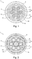
- Figs. 1 and 2 each show a heavy-current charging cable 1 for charging an electric vehicle according to preferred embodiments in a sectional view.
- the cable 1 comprises one central heavy-current wire 2 serving as ground which comprises a central conductor 3 extending in a longitudinal direction orthogonal to the figure layer and a central wire insulation 4 surrounding the central conductor 3. While not shown, the central conductor 2 can be provided non-insulated.
- the central conductor 2 comprises a cross section of 25 mm 2 , while the central wire insulation 3 comprises thickness of 0,5 to 2 mm.
- the heavy-current charging cable 1 further comprises six heavy-current power wires 5, each configured for conducting positive and negative direct current, DC.
- the six heavy-current power wires 5 each extend parallel to the central wire 2 and are arranged around thereby surrounding the central heavy-current wire 2 such that alternately one heavy-current power wire 5 conveys positive DC and the another, next heavy-current power wire 5 conveys negative DC.
- Each heavy-current power wire 5 comprises a power conductor 6 and a power wire insulation 7 surrounding said power conductor 6.
- Each power conductor 6 comprises a cross section of 16 mm 2 , while the power wire insulation 7 comprises thickness of 0,5 to 2 mm. With such arrangement of the central wire 2 and the power wires 5 a packing factor is 0,777 for the cable 1 is achieved.
- the central conductor 3 and the power conductors 6 consists of copper, aluminium or a mixture thereof and/or comprise wire strands.
- the power conductors 5 conducting positive current are arranged on one side on the central heavy-current wire 2 and the power conductors 5 conducting negative current are arranged on the other side on the central heavy-current wire 2.
- the cable 1 further comprise a liquid tight inner hose 8 and a liquid tight outer hose 9 made of a polymer-based material and/or comprising extruded polymer layers.
- Both the liquid tight inner hose 8 and the liquid tight outer hose 9 extend in the longitudinal direction, whereby the liquid tight inner hose 8 surrounds the central wire 2 and the power wires 5, thereby defining a first hollow area 10.
- the liquid tight inner hose 8 does not surround the central wire 2 and the power wires 5 such that said wires 2, 5 are arranged tight to each other and with the inner hose 8.
- Wire spacers 11 are arranged in regular pattern between the central wire 2, the power wires 5 and the inner hose 8 for facilitating such arrangement.
- the outer hose 9 surrounds the inner hose 8 thereby defining a second hollow area 12 between both hoses 8, 9.
- Hose spacers 13 are arranged in regular pattern between both hoses 8, 9 for facilitating such arrangement so that the hoses 8, 9 do not touch each other at any location.
- Inner hose 8 comprises an inner diameter of 25 mm and an outer diameter of 29 mm, whereby the outer hose 9 comprises an inner diameter of 33 mm and an outer diameter of 40 mm.
- First hollow area 10 and second hollow area 12 are each filled with a liquid coolant to flow between the central wire 2 and the power wires 5 along the longitudinal direction within the inner hose 8 and thus around respectively in direct contact with each the central wire 2 and all power wires 5 and flow between the inner hose 8 and the outer hose 9.
- the liquid coolant comprises oil, a water and glycol mixture, a water and salt mixture, and /or halogenated hydrocarbon compounds.
- sensor wires 14 are provided in the hollow area 10 and second hollow area 12 extending in longitudinal direction for submitting, among others, control pilot, CP, and proximity pilot, PP, signals.
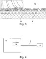
- Fig. 2 comprises in addition to the implementation of Fig. 1 a flexible metal tube 15, which is arranged between the inner hose 8 and the outer hose 9, whereby the outer hose 9 is extruded on the flexible metal tube 14.
- Fig. 3 shows the flexible metal tube 15 in two sectional views besides each other, on the left as semi-perspective view and on the right as sectional view.
- Fig. 4 shows an electric vehicle supply equipment, EVSE, 16, which comprising the charging cable 1 and a charging connector 16.
- the EVSE 16 is connected via a transformer and/or a converter for receiving electrical energy from an AC grid, not shown, which is transformed and/or converted to DC for being supplied via the charging cable 1 having a length of 6 m to the electric vehicle connected thereto via the charging connector 17 to charge the electric vehicle with a current rating greater or equal than 500 A DC and a voltage rating greater or equal than 1000 V DC.
- the EVSE 16 comprises a cooling unit 18 having a liquid coolant reservoir, a coolant-to-air heat exchanger and a respective pump for circulating the liquid coolant from the cooling unit 18 between the inner hose 8 and the outer hose 9 towards the charging connector 17.
- the charging connector 17 is configured for returning the liquid coolant through the inner hose 8 towards the cooling unit 18 such that thereby the liquid coolant circulates around the central wire 2 and all power wires 5 for cooling the respective central conductor 3 and the power conductors 6.
Landscapes
- Engineering & Computer Science (AREA)
- Power Engineering (AREA)
- Transportation (AREA)
- Mechanical Engineering (AREA)
- Electric Propulsion And Braking For Vehicles (AREA)
Abstract
Description
- The invention relates to a heavy-current charging cable for charging an electric vehicle, comprising a central heavy-current wire configured for serving as ground, the central wire comprising a central conductor and extending in a longitudinal direction, and a plurality of heavy-current power wires configured for conducting positive and negative direct current, DC, each of said power wires comprising a power conductor and a power wire insulation surrounding said power conductor, the power wires surrounding and extending parallel to the central wire. The invention further relates to an electric vehicle supply equipment comprising the heavy-current charging cable and a cooling unit, as well as to a respective method for cooling a heavy-current charging cable.
- A liquid cooled charging cable for high power charging of electric vehicles, EVs, with more than 250 A consists typically of a cable arrangement, including a plurality of conductors with the charging cable and a charging connector, wherein power contacts are located. The coolant loop in the charging cable is generally designed to remove heat generated by Joule effect both in the charging cable and in the charging connector. The liquid cooled charging cable is connected to a cooling unit, generally located inside a charge post, where the heat provided to the coolant by Joule effect is preferably dissipated to the surrounding ambient air.
- Such liquid cooling is necessary for high-current fast EV chargers, mainly because the liquid cooling avoids other necessary use of bulky charging conductors which would make the charging cable very difficult to handle. Non-cooled charging cable are typically used for charging current up to 250 A as otherwise the charging cable becomes too large, heavy and stiff for the user. Thus, active liquid cooling is essential, by using a coolant fluid such as for example oils, water/glycol or water/salts mixtures, halogenated hydrocarbon compounds, etc., and said cooling unit for conveying and respective cooling of the liquid coolant.
- In a conservative approach, the electrical metallic conductors present in the charging cable, typically Cu, are electrically insulated to prevent shorts between the conductors or to ground through the liquid coolant. In this case, non-insulating coolants, like water/glycol mixtures, can be used, which bring some advantages. First, these mixtures exhibit chemical compatibility with a variety of materials, including rubberlike polymeric materials to be used for electrical insulation, for example silicone rubbers or thermoplastic elastomers. Such materials remain soft even at low temperature. Furthermore, some water-based mixtures have low viscosity even below - 30°C, so a heating system and/or a large pump are generally not required to enable a proper operation of the charge post at low temperatures. On the other hand, cooling performance is penalized due to the presence of insulating, and poor thermally conducting, layers between the conductors and the liquid coolant, limiting maximum allowed power rating of the liquid cooled charging cable.
- In more advanced solutions known from prior art, the liquid coolant flows directly around the bare and thus uninsulated conductors providing more efficient cooling. In this case, insulating liquids have to be used, like synthetic oils or halogenated hydrocarbon compounds, with drawbacks in terms of their low temperature performance due to increased viscosity and their environmental friendliness, respectively. Many dielectric fluids become very viscous at temperatures below -20°C. It is worth to mention that data available on chemical compatibility between synthetic oils and plastic materials is scarce and unreliable, raising also questions with regards to long term stability.
- Existing liquid cooled charging cable solutions suffer drawbacks in terms of safety, reliability and/or performance. For instance, one known solution shows poor performance at low temperatures such as below -20°C because of excessive pressure drop and problematic material compatibility between the liquid coolant (synthetic oil) and the polymeric material used for flow channels. Another known solution adopts an indirect cooling approach with a water/glycol mixture flowing in separate ducts. The charging cable-to-electric vehicle contacts are well thermally controlled but the heat generated in the conductors is not dissipated effectively. As a consequence, a higher cross section of copper conductors is adopted thus making the cable heavier and a nominal current of 500 A can be reached at 40°C ambient, only if a cooling unit with a refrigerant loop is used. In addition, both solutions are considered weak in terms of reliability since during normal operation, materials temperature very limit is reached.
- Furthermore, in existing solutions, coolant flow can be easily blocked as an example by inner clogging or pipe crushing. This represents potentially a safety issue, especially during a charging session because the thermal runaway can be extremely fast and the interlock system in the charge post may only intervene with a certain delay.
- It is therefore an object of the invention to provide a charging cable and respective charge post solution for high power charging at power ratings equal or greater to 500kW increasing reliability and safety standards.
- The object of the invention is solved by the features of the independent claims. Preferred embodiments are detailed in the dependent claims.
- Thus, the object is solved by a heavy-current charging cable for charging an electric vehicle, comprising:
- a central heavy-current wire configured for serving as ground, the central wire comprising a central conductor and extending in a longitudinal direction,
- a plurality of heavy-current power wires configured for conducting positive and negative direct current, DC, each of said power wires comprising a power conductor and a power wire insulation surrounding said power conductor, the power wires extending parallel to the central wire,
- a liquid tight inner hose extending in the longitudinal direction and surrounding the central wire and the power wires thereby defining a first hollow area comprising liquid coolant to flow between the central wire and the power wires along the longitudinal direction, and
- a liquid tight outer hose extending in the longitudinal direction and surrounding the inner hose thereby defining a second hollow area comprising liquid coolant to flow between the inner hose and the outer hose along the longitudinal direction.
- The proposed solution provides a heavy-current charging cable suitable for High Power Charging, HPC, of Electrical Vehicles, EV. The solution enables charging at 500A and 1000V, meeting today's standards for fast DC charging, in particular allowing 100 km of driving within 3 to 5 min charging, and can be also adapted to evolving future requirements towards higher ratings such as charging with 600 A at 1500 V i.e. at 900 kW. Compared to prior art solution, the proposed solution provides improved thermal and mechanical performance, and ease in manufacturing and assembly. As revealed by thermal simulations, with a commonly used material for the power wire insulation respectively core wire insulation described below, a maximum temperature of the respective conductors remains below 90°C when a current of 500 A is flowing at ambient temperature up to 50°C. As compared to existing solution as known from prior art, the maximum temperature of conductors at 500 A is reduced by 20 to 25°C.
- The simple preferably cylindrical design of all components of the cable provides ease during manufacturing of all components and also in assembling the final liquid cooled cable. The core part of the cable comprised of the conductor wires and the inner hose can be easily assembled together or purchased in a ready cable form from an external cable manufacturer. At a second step the aforementioned assembly is inserted into the outer hose. Thus, the proposed solution is readily scalable towards higher power ratings by suitably modifying the dimensions of the conductors, of the inner and outer hose as well as the flow rate of the liquid coolant.
- The cable can be part of an electric vehicle supply equipment, EVSE, also referred to as electric vehicle, EV, charging station, electric recharging point, charging point, charge point, charge post or electronic charging station, ECS. The EVSE is an element in an infrastructure that supplies electric energy for recharging of electric vehicles, including electric cars, neighbourhood electric vehicles and plug-in hybrids, via said charging cable and a charging connector to the EV. EVSEs usually comply with standards for electric vehicle fast charging, such as the so-called Combined Charging System, CCS, protocol according to IEC 61851-23 and SAE J1772 standard for charging electric vehicles both in the US and in the European Union, EU. The Combined Charging System, CCS, protocol is a fast charging method for charging electric vehicles delivering high-voltage direct current via a charging connector derived from SAE J1772 standard (IEC Type 1) or IEC
Type 2 connector. Automobile manufactures that support CCS include Jaguar, Volkswagen, General Motors, BMW, Daimler, Ford, FCA, Tesla and Hyundai. The CSS standard is controlled by the so called CharIN consortium. Besides other protocols such as, for example, CHAdeMO, as abbreviation of CHArge de Move, or GB/T, in particular according to 20234.3-2011 standard. The proposed solution can be advantageously used with even higher charging currents such as more than 500A and/or in combination with newer standards not yet defined requiring higher currents. - Preferably the inner hose, the outer hose and/or the arrangement of the power wires surrounding the central wire comprise a cylindrical or cylindrical-like shape respectively design. The first hollow area and/or the second hollow area shall preferably be understood as an 'empty space' through which the liquid coolant can be conveyed respectively flow. The inner hose and/or the outer hose can be provided as a cooling jacket and/or as an annular, integral jacket which is extruded on and in which defines the respective hollow chamber. The term heavy-current shall be understood that the conductors and the respective insulation is configured for conveying total currents equal to or greater than 500 A. In a further implementation the cable may comprise a plurality of core wires.
- According to a preferred implementation the central wire comprises a central wire insulation surrounding the central conductor or is non-insulated, and/or the power wires surrounding the central wire. The term surrounding shall be understood that, in a sectional view, the central wire is encompassed by the power wires respectively the power wires and the core wires are encompassed by the inner hose.
- In another preferred implementation the cable comprises six power wires, each three of the power wires conducting positive and negative DC and arranged alternately around the central heavy-current core. Alternatively, the conductors conducting positive current are arranged on one side on the central heavy-current core and the conductors conducting negative current are arranged on the other side on the central heavy-current core. According to a further preferred implementation the central wire and the power wires are arranged such that the packing factor is 0,777. The packing factor is preferably defined as per DIN EN 60317-11 and/or as conductor area, of all conductors, divided total area, used by all conductors preferably within the inner hose. Usage of seven wires, three power wires for DC+ respectively power plus, three power wires for DC- respectively power minus and one core wire for grounding, is a favourable topology since it allows a high packing factor as 0.777. Furthermore, the total current and the total heat losses due to Joule effect can be divided into six conductors, thus reducing the heat flux on each conductor and minimizing the effect of the insulation layer on the total thermal resistance.
- Generally cross sections of the power wires and of the core wire, thickness of the power wire insulation and of the outer hose and/or of the inner hose and/or cable length can be arbitrarily chosen, preferably provided that sufficient dielectric strength is assured between conductors. According to a preferred implementation a cross section of the power wires is 16 mm2, a cross section of the core wire is 25 mm2, a thickness of the power wire insulation is in a range of 0,5 to 2,0 mm, the outer hose and/or the inner hose comprises a thickness in a range of 2 to 10 mm, and/or the cable comprises a length of 6 m. Such parameters allow charging at 500 A DC and 1000 V DC. Such wise the term heavy-current shall be understood that a total current greater or equal 500 A is meant respectively can be conducted by the respective conductors or wires.
- According to a preferred implementation the liquid coolant comprises oil, a water and glycol mixture, a water and salt mixture, and /or halogenated hydrocarbon compounds. As coolant liquid a non-insulating fluid such as for example water/glycol mixtures can be used since the proposed solution is compatible with indirect cooling approach. According to numerical calculations, with a preferred coolant having a kinematic viscosity at -40°C lower than 470 cSt, a maximum pressure drop in a 6 m long cable is of 4 bar, at a flow rate below 1 l/min, and such wise suitable for thermal control of the cable's conductors.
- Inner hose and/or outer hose can be generally provided from an ordinary but preferably insulating material. Preferably inner hose and/or outer hose are provided as a tube and/or as a sleeving. In a preferred implementation the inner hose and/or the outer hose comprise a polymer-based material and/or extruded polymer layers. Most preferably, inner hose and/or outer hose comprise polyamide.
- In another preferred implementation the outer hose comprises a flexible metal tube arranged between the inner hose and the outer hose and whereby the outer hose is extruded on the flexible metal tube. In an alternative implementation the flexible metal tube is arranged on the outer hose thereby encompassing the outer hose. Such flexible metal tube provides enhanced safety and mechanical robustness for the cable. In particular, in case of a damage in the outer hose the user of the cable is still protected to any exposure to the high voltage cable by both the flexible metal hose, which is preferably also provided water tight, and the inner hose. Furthermore, the flexible metal hose provides required mechanical protection in the event an electric vehicle drives over the liquid cooled cable. Therefore, the flexible metal tube is preferably configured to comprise a lateral crushing strength in the range of 65.5 kN/m. The metal tube may comprise, in cross-section, a strip-wound hose made from galvanic steel, for example cut of carcass wall. Most preferably the metal tube is made of steel, galvanized steel or aluminum, preferably comprising strip-wound profiles to provide necessary flexibility and/or having a bending radius below 300 mm, preferably below 150 mm.
- Generally, the central conductor and/or the power conductors may comprise an arbitrary conducting material. According to a preferred implementation the central conductor and/or the power conductors comprise copper and/or aluminium wires and/or wire strands. The proposed cable can be simply and thus cost efficient manufactured, whereby in particular the usage of Aluminium instead of Copper conductors result in significant cost reduction. Aluminium has about 60% of the conductivity of copper but has only 30% of the weight of copper. That means that a bare wire of aluminium weighs half as much as a bare wire of copper that has the same electrical resistance. Thus, by keeping constant the total weight per meter of the cable, usage of Aluminium advantageously results in about half the Ohmic losses as compared to Copper. Special aluminium alloys, such as for example AA-8000 series, exhibit similar to copper creep and elongation properties, meeting the requirements of ASTM B800 for electrical purposes. Thus, thermal performance can be further improved by using Aluminium instead of Copper wires respectively conductors.
- According to a further preferred implementation the central wire, the power wires and/or the inner hose are arranged distant from each other and/or comprising wire spacers to arrange the central wire, the power wires and/or the inner hose distant from each other. In another preferred implementation the inner hose and the outer hose are arranged distant from each other and/or comprising hose spacers to arrange the inner hose and the outer hose distant from each other. The wire spacers and/or the hose spacers can be provided as plastic spacers and/or are preferably arranged in a regular pattern. The distance respectively size of the wire spacers and/or the hose spacers can be for example 2, 3 or 5 mm such that sufficient liquid coolant can flow in the respective hollow area.
- In a further preferred implementation, the cable comprises at least a sensor wire extending in the longitudinal direction and arranged within the inner hose and/or between the inner hose and the outer hose. The first hollow area and/or the second hollow area between the electrical conductors as well as the space between the two hoses can host in particular thin wires used, for example, for sensing of various parameters such as temperature, humidity, light, acceleration, electrical resistance, etc. either in the charging connector or the liquid cooled cable as such. In a preferred implementation, the sensor wire comprises a Proximity Pilot, PP, wire for pre-insertion signalling and/or a Control Pilot, CP, wire for post-insertion signalling, in particular as per SAE J1772 and/or IEC 61851 standard. Most preferably, the sensor wire or a plurality thereof is arranged between the inner hose and the outer hose. Such way safety is also improved by early detection of damages in the outermost layers by placing the Control Pilot and/or Proximity Pilot wire in said hollow second area between the inner and outer hoses.
- The object is further solved by an electric vehicle supply equipment, EVSE, comprising the charging cable as described before, a cooling unit and a charging connector, whereby
- the charging cable is connected between the cooling unit and the charging connector,
- the cooling unit is configured for conveying the liquid coolant from the cooling unit between the inner hose and the outer hose towards the charging connector and
- the charging connector is configured for returning the liquid coolant through the inner hose towards the cooling unit.
- Compared to prior art solution, the proposed solution provides improved thermal and mechanical performance, and ease in manufacturing and assembly. The cooling unit is preferably configured for conveying a coolant having a kinematic viscosity at -40°C lower than 470cSt having a maximum pressure drop in a 6 m long cable of 4 bar at a flow rate below 1 I/min. The cooling unit preferably comprises means for storing, cooling and/or conveying the liquid coolant across the entire extension of the cable. Cooling unit, cable and charging connector are preferably provided as closed cooling circuit, in particular by means of the inner hose and the outer hose.
- In a preferred implementation the EVSE is configured to charge the electric vehicle with a current rating equal to or greater than 500 A DC and/or a voltage rating equal to or greater than 1000 V DC. The EVSE may comprise a transformer and/or a converter for connecting to respectively receiving electrical energy from an AC grid, which is transformed and/or converted to DC for being supplied via the charging cable to the electric vehicle connected thereto via the charging connector.
- The object is even further solved by a method for liquid cooling a heavy-current charging cable for charging an electric vehicle, the cable comprising
- a central heavy-current wire configured for serving as ground, the central wire comprising a central conductor and extending in a longitudinal direction,
- a plurality of heavy-current power wires configured for conducting positive and negative direct current, DC, each of said power wires comprising a power conductor and a power wire insulation surrounding said power conductor, the power wires extending parallel to the central wire,
- a liquid tight inner hose extending in the longitudinal direction and surrounding the central wire and the power wires thereby defining a first hollow between the central wire and the power wires along the longitudinal direction, and
- a liquid tight outer hose extending in the longitudinal direction and surrounding the inner hose thereby defining a second hollow area between the inner hose and the outer hose along the longitudinal direction, the method comprising the step of:
Conveying liquid coolant through the first hollow area and the second hollow area. - Further embodiments and advantages of the method are directly and unambiguously derived by the person skilled in the art from the cable as described before.
- These and other aspects of the invention will be apparent from and elucidated with reference to the implementations described hereinafter.
- In the drawings:
- Fig. 1
- shows a heavy-current charging cable according to a preferred implementation in a sectional view,
- Fig. 2
- shows a heavy-current charging cable according to another preferred implementation in a sectional view,
- Fig. 3
- shows a flexible metal tube of the heavy-current charging cable according to
Fig. 2 in two sectional views, - Fig. 4
- shows an electric vehicle supply equipment comprising the cable of
Figs. 1 or 2 according to a preferred implementation in a schematic view. -
Figs. 1 and 2 each show a heavy-current charging cable 1 for charging an electric vehicle according to preferred embodiments in a sectional view. Thecable 1 comprises one central heavy-current wire 2 serving as ground which comprises a central conductor 3 extending in a longitudinal direction orthogonal to the figure layer and acentral wire insulation 4 surrounding the central conductor 3. While not shown, thecentral conductor 2 can be provided non-insulated. Thecentral conductor 2 comprises a cross section of 25 mm2, while the central wire insulation 3 comprises thickness of 0,5 to 2 mm. - The heavy-
current charging cable 1 further comprises six heavy-current power wires 5, each configured for conducting positive and negative direct current, DC. The six heavy-current power wires 5 each extend parallel to thecentral wire 2 and are arranged around thereby surrounding the central heavy-current wire 2 such that alternately one heavy-current power wire 5 conveys positive DC and the another, next heavy-current power wire 5 conveys negative DC. Each heavy-current power wire 5 comprises apower conductor 6 and apower wire insulation 7 surrounding saidpower conductor 6. Eachpower conductor 6 comprises a cross section of 16 mm2, while thepower wire insulation 7 comprises thickness of 0,5 to 2 mm. With such arrangement of thecentral wire 2 and the power wires 5 a packing factor is 0,777 for thecable 1 is achieved. The central conductor 3 and thepower conductors 6 consists of copper, aluminium or a mixture thereof and/or comprise wire strands. Alternatively, thepower conductors 5 conducting positive current are arranged on one side on the central heavy-current wire 2 and thepower conductors 5 conducting negative current are arranged on the other side on the central heavy-current wire 2. - The
cable 1 further comprise a liquid tightinner hose 8 and a liquid tightouter hose 9 made of a polymer-based material and/or comprising extruded polymer layers. Both the liquid tightinner hose 8 and the liquid tightouter hose 9 extend in the longitudinal direction, whereby the liquid tightinner hose 8 surrounds thecentral wire 2 and thepower wires 5, thereby defining a firsthollow area 10. In other words, the liquid tightinner hose 8 does not surround thecentral wire 2 and thepower wires 5 such that saidwires inner hose 8.Wire spacers 11 are arranged in regular pattern between thecentral wire 2, thepower wires 5 and theinner hose 8 for facilitating such arrangement. In an analogous manner theouter hose 9 surrounds theinner hose 8 thereby defining a secondhollow area 12 between bothhoses Hose spacers 13 are arranged in regular pattern between bothhoses hoses Inner hose 8 comprises an inner diameter of 25 mm and an outer diameter of 29 mm, whereby theouter hose 9 comprises an inner diameter of 33 mm and an outer diameter of 40 mm. - First
hollow area 10 and secondhollow area 12 are each filled with a liquid coolant to flow between thecentral wire 2 and thepower wires 5 along the longitudinal direction within theinner hose 8 and thus around respectively in direct contact with each thecentral wire 2 and allpower wires 5 and flow between theinner hose 8 and theouter hose 9. The liquid coolant comprises oil, a water and glycol mixture, a water and salt mixture, and /or halogenated hydrocarbon compounds. In addition to the liquid coolant,sensor wires 14 are provided in thehollow area 10 and secondhollow area 12 extending in longitudinal direction for submitting, among others, control pilot, CP, and proximity pilot, PP, signals. - The implementation in
Fig. 2 comprises in addition to the implementation ofFig. 1 aflexible metal tube 15, which is arranged between theinner hose 8 and theouter hose 9, whereby theouter hose 9 is extruded on theflexible metal tube 14.Fig. 3 shows theflexible metal tube 15 in two sectional views besides each other, on the left as semi-perspective view and on the right as sectional view. -
Fig. 4 shows an electric vehicle supply equipment, EVSE, 16, which comprising the chargingcable 1 and a chargingconnector 16. TheEVSE 16 is connected via a transformer and/or a converter for receiving electrical energy from an AC grid, not shown, which is transformed and/or converted to DC for being supplied via the chargingcable 1 having a length of 6 m to the electric vehicle connected thereto via the chargingconnector 17 to charge the electric vehicle with a current rating greater or equal than 500 A DC and a voltage rating greater or equal than 1000 V DC. TheEVSE 16 comprises acooling unit 18 having a liquid coolant reservoir, a coolant-to-air heat exchanger and a respective pump for circulating the liquid coolant from the coolingunit 18 between theinner hose 8 and theouter hose 9 towards the chargingconnector 17. The chargingconnector 17 is configured for returning the liquid coolant through theinner hose 8 towards the coolingunit 18 such that thereby the liquid coolant circulates around thecentral wire 2 and allpower wires 5 for cooling the respective central conductor 3 and thepower conductors 6. - While the invention has been illustrated and described in detail in the drawings and foregoing description, such illustration and description are to be considered illustrative or exemplary and not restrictive; the invention is not limited to the disclosed embodiments. Other variations to be disclosed embodiments can be understood and effected by those skilled in the art in practicing the claimed invention, from a study of the drawings, the disclosure, and the appended claims. In the claims, the word "comprising" does not exclude other elements or steps, and the indefinite article "a" or "an" does not exclude a plurality. The mere fact that certain measures are recited in mutually different dependent claims does not indicate that a combination of these measures cannot be used to advantage. Any reference signs in the claims should not be construed as limiting scope.
-
- 1
- cable
- 2
- central heavy-current wire
- 3
- central conductor
- 4
- central wire insulation
- 5
- heavy-current power wire
- 6
- power conductor
- 7
- power wire insulation
- 8
- inner hose
- 9
- outer hose
- 10
- first hollow area
- 11
- wire spacer
- 12
- second hollow area
- 13
- hose spacer
- 14
- sensor wire
- 15
- metal tube
- 16
- electric vehicle supply equipment
- 17
- charging connector
- 18
- cooling unit
Claims (15)
- A heavy-current charging cable (1) for charging an electric vehicle, comprising:a central heavy-current wire (2) configured for serving as ground, the central heavy-current wire (2) comprising a central conductor (3) and extending in a longitudinal direction,a plurality of heavy-current power wires (5) configured for conducting positive and negative direct current, DC, each of said heavy-current power wires (5) comprising a power conductor (6) and a power wire insulation (7) surrounding said power conductor (6), the heavy-current power wires (5) extending parallel to the central wire,a liquid tight inner hose (8) extending in the longitudinal direction and surrounding the heavy-current central wire (2) and the heavy-current power wires (5) thereby defining a first hollow area (10) comprising liquid coolant to flow between the heavy-current central wire (2) and the heavy-current power wires (5) along the longitudinal direction, anda liquid tight outer hose (9) extending in the longitudinal direction and surrounding the inner hose (8) thereby defining a second hollow area (12) comprising liquid coolant to flow between the inner hose (8) and the outer hose (9) along the longitudinal direction.
- Charging cable (1) according to the previous claim, whereby the heavy-current central wire (2) comprises a central wire insulation (4) surrounding the central conductor (3) or is non-insulated, and/or the heavy-current power wires (5) surrounding the heavy-current central wire (2).
- Charging cable (1) according to any of the previous claims, whereby the cable (1) comprises six heavy-current power wires (5), each three of the heavy-current power wires (5) conducting positive and negative DC and arranged alternately around the central heavy-current wire (2), or, whereby the cable (1) comprises six heavy-current power wires (5) and whereby the heavy-current power wires (5) conducting positive current are arranged on one side on the central heavy-current wire (2) and the heavy-current power wires (5) conducting negative current are arranged on the other side on the central heavy-current wire (2)
- Charging cable (1) according to any of the previous claims, whereby the heavy-current central wire (2) and the heavy-current power wires (5) are arranged such that the packing factor is 0,777.
- Charging cable (1) according to any of the previous claims, whereby a cross section of the heavy-current power wires (5) is 16 mm2, a cross section of the heavy-current core wire (2) is 25 mm2, a thickness of the power wire insulation (7) is in a range of 0,5 to 2,0 mm, the outer hose (9) comprises a thickness in a range of 5 to 10 mm, and/or the cable (1) comprises a length of 6 m.
- Charging cable (1) according to any of the previous claims, whereby the liquid coolant comprises oil, a water and glycol mixture, a water and salt mixture, and /or halogenated hydrocarbon compounds.
- Charging cable (1) according to any of the previous claims, whereby the inner hose (8) and/or the outer hose (9) comprise a polymer-based material and/or extruded polymer layers.
- Charging cable (1) according to any of the previous claims, whereby the outer hose (9) comprises a flexible metal tube (15) arranged between the inner hose (8) and the outer hose (9) and whereby the outer hose (9) is extruded on the flexible metal tube (15).
- Charging cable (1) according to any of the previous claims, whereby the central conductor (3) and/or the power conductors (6) comprise copper and/or aluminium wires and/or wire strands.
- Charging cable (1) according to any of the previous claims, whereby the central wire, the power wires and/or the inner hose (8) are arranged distant from each other and/or comprising wire spacers (15) to arrange the central heavy-current wire (2), the power heavy-current wires (6) and/or the inner hose (8) distant from each other.
- Charging cable (1) according to any of the previous claims, whereby the inner hose (8) and the outer hose (9) are arranged distant from each other and/or comprising hose spacers (13) to arrange the inner hose (8) and the outer hose (9) distant from each other.
- Charging cable (1) according to any of the previous claims, comprising at least a sensor wire (14) extending in the longitudinal direction and arranged within the inner hose (8) and/or between the inner hose (8) and the outer hose (9).
- Electric vehicle supply equipment, EVSE, (16) comprising the charging cable (1) according to any of the previous claims, a cooling unit (18) and a charging connector (17), wherebythe charging cable (1) is connected between the cooling unit (18) and the charging connector (17),the cooling unit (18) is configured for conveying the liquid coolant from the cooling unit (18) between the inner hose (8) and the outer hose (9) towards the charging connector (17) andthe charging connector (17) is configured for returning the liquid coolant through the inner hose (8) towards the cooling unit (18).
- EVSE (16) according to the previous claim configured to charge the electric vehicle with a current rating equal to or greater than 500 A DC and/or a voltage rating equal to or greater than 1000 V DC.
- Method for liquid cooling a heavy-current charging cable (1) for charging an electric vehicle, the cable (1) comprisinga central heavy-current wire (2) configured for serving as ground, the central heavy-current wire (2) comprising a central conductor (3) and extending in a longitudinal direction,a plurality of heavy-current power wires (5) configured for conducting positive and negative direct current, DC, each of said heavy-current power wires (5) comprising a power conductor (6) and a power wire insulation (7) surrounding said power conductor (6), the heavy-current power wires (5) extending parallel to the central heavy-current wire (2),a liquid tight inner hose (8) extending in the longitudinal direction and surrounding the central heavy-current wire (2) and the heavy-current power wires (5) thereby defining a first hollow area (10) between the central heavy-current wire (2) and the heavy-current power wires (5) along the longitudinal direction, anda liquid tight outer hose (9) extending in the longitudinal direction and surrounding the inner hose (8) thereby defining a second hollow area (12) between the inner hose (8) and the outer hose (9) along the longitudinal direction, the method comprising the step of:
Conveying liquid coolant through the first hollow area (10) and the second hollow area (12).
Priority Applications (4)
| Application Number | Priority Date | Filing Date | Title |
|---|---|---|---|
| EP19188275.2A EP3770925B1 (en) | 2019-07-25 | 2019-07-25 | Heavy-current charging cable for charging an electric vehicle |
| CN202080053429.0A CN114175183B (en) | 2019-07-25 | 2020-07-24 | High-current charging cables for charging electric vehicles |
| PCT/EP2020/071025 WO2021014009A1 (en) | 2019-07-25 | 2020-07-24 | Heavy-current charging cable for charging an electric vehicle |
| US17/583,015 US12083911B2 (en) | 2019-07-25 | 2022-01-24 | Heavy-current charging cable for charging an electric vehicle |
Applications Claiming Priority (1)
| Application Number | Priority Date | Filing Date | Title |
|---|---|---|---|
| EP19188275.2A EP3770925B1 (en) | 2019-07-25 | 2019-07-25 | Heavy-current charging cable for charging an electric vehicle |
Publications (3)
| Publication Number | Publication Date |
|---|---|
| EP3770925A1 true EP3770925A1 (en) | 2021-01-27 |
| EP3770925C0 EP3770925C0 (en) | 2023-12-27 |
| EP3770925B1 EP3770925B1 (en) | 2023-12-27 |
Family
ID=67438846
Family Applications (1)
| Application Number | Title | Priority Date | Filing Date |
|---|---|---|---|
| EP19188275.2A Active EP3770925B1 (en) | 2019-07-25 | 2019-07-25 | Heavy-current charging cable for charging an electric vehicle |
Country Status (4)
| Country | Link |
|---|---|
| US (1) | US12083911B2 (en) |
| EP (1) | EP3770925B1 (en) |
| CN (1) | CN114175183B (en) |
| WO (1) | WO2021014009A1 (en) |
Cited By (3)
| Publication number | Priority date | Publication date | Assignee | Title |
|---|---|---|---|---|
| WO2022079706A1 (en) * | 2020-10-15 | 2022-04-21 | Green Business Development Ltd | An electric vehicle charging cable and a method of making |
| CN114464363A (en) * | 2021-12-20 | 2022-05-10 | 华为数字能源技术有限公司 | Liquid cooling cable, charging gun and charging equipment |
| EP4465448A1 (en) * | 2023-05-17 | 2024-11-20 | Witzenmann GmbH | Temperature-controllable power line device, method for producing same, and method for controlling the temperature of a power line |
Families Citing this family (9)
| Publication number | Priority date | Publication date | Assignee | Title |
|---|---|---|---|---|
| EP3744562B1 (en) * | 2019-05-27 | 2022-04-13 | ABB Schweiz AG | Electric vehicle supply equipment for charging an electrical vehicle |
| EP4125098A1 (en) * | 2021-07-30 | 2023-02-01 | Aptiv Technologies Limited | A power cable assembly for a power distribution system having an integrated cooling system |
| DE102021123619A1 (en) | 2021-09-13 | 2023-03-16 | HARTING Automotive GmbH | Line device for a motor vehicle charging cable |
| CN114267486B (en) * | 2021-11-30 | 2025-04-01 | 长春捷翼汽车科技股份有限公司 | Liquid cooling cable |
| US12415430B2 (en) | 2022-10-03 | 2025-09-16 | Ford Global Technologies, Llc | Battery charging system for electrified vehicle including interface for cable and housing |
| EP4480737B1 (en) * | 2023-06-22 | 2026-04-15 | ABB E-mobility B.V. | Dc charging cable assembly for charging an electrical vehicle, dc charging system for charging an electrical vehicle and method for charging an electrical vehicle |
| CN117022013B (en) * | 2023-08-16 | 2025-10-03 | 福建星云电子股份有限公司 | A temperature control method for liquid-cooled supercharging pile |
| CN119305431B (en) * | 2024-09-25 | 2025-11-14 | 中国第一汽车股份有限公司 | Control methods for vehicle charging systems, vehicle charging systems, vehicles and charging media |
| DE102024132428A1 (en) | 2024-11-07 | 2026-05-07 | Dr. Ing. H.C. F. Porsche Aktiengesellschaft | Coolable power cable and battery |
Citations (5)
| Publication number | Priority date | Publication date | Assignee | Title |
|---|---|---|---|---|
| US20170144558A1 (en) * | 2015-11-19 | 2017-05-25 | Dr. Ing. H.C. F. Porsche Aktiengesellschaft | Electric line arrangement |
| WO2017207266A1 (en) * | 2016-06-01 | 2017-12-07 | Phoenix Contact E-Mobility Gmbh | Charging cable for transmitting electric energy, charging plug and charging station for discharging electric energy to a recipient of electric energy |
| US20180158572A1 (en) * | 2016-12-05 | 2018-06-07 | Leoni Kabel Gmbh | Heavy-current cable and power supply system with a heavy-current cable |
| DE102017217506A1 (en) * | 2017-09-29 | 2019-04-04 | Audi Ag | Method for charging an energy store of a motor vehicle, motor vehicle and charging cable |
| US20190217728A1 (en) * | 2018-01-15 | 2019-07-18 | Dr. Ing. H.C. F. Porsche Aktiengesellschaft | Fast charging station with charging cable and temperature control device for the charging cable |
Family Cites Families (12)
| Publication number | Priority date | Publication date | Assignee | Title |
|---|---|---|---|---|
| US3483313A (en) * | 1968-04-04 | 1969-12-09 | Plastic Wire & Cable Corp | Flotation cable |
| US5399095A (en) * | 1991-03-26 | 1995-03-21 | Square D Company | Variable phase positioning device |
| JPWO2007032391A1 (en) * | 2005-09-13 | 2009-03-19 | 株式会社オートネットワーク技術研究所 | Conductor for vehicle |
| TWM340532U (en) * | 2008-01-15 | 2008-09-11 | Zheng-Xiong Wu | Energy-saving electric wire and cable |
| CA3250062A1 (en) * | 2016-05-20 | 2025-06-17 | Southwire Company, Llc | Liquid cooled charging cable system |
| JP6078198B1 (en) * | 2016-07-29 | 2017-02-08 | 株式会社フジクラ | Power supply cable and power supply cable with connector |
| DE102016118193A1 (en) * | 2016-09-27 | 2018-03-29 | Phoenix Contact E-Mobility Gmbh | Electrical cable with a coolant line |
| CN106887277A (en) * | 2017-04-08 | 2017-06-23 | 江苏晟彼特特种线缆有限公司 | Electric automobile charging pile cools down cable |
| DE102018102207A1 (en) * | 2018-02-01 | 2019-08-01 | Dr. Ing. H.C. F. Porsche Aktiengesellschaft | Vehicle charging cable |
| CN109215872A (en) * | 2018-09-06 | 2019-01-15 | 宁波聚亿新能源科技有限公司 | A kind of liquid cooling cable and the electric vehicle charging cables cooling device using it |
| DE102018122680B3 (en) * | 2018-09-17 | 2020-02-20 | Dr. Ing. H.C. F. Porsche Aktiengesellschaft | Vehicle charging cable |
| US11180044B2 (en) * | 2019-06-14 | 2021-11-23 | Honda Motor Co., Ltd. | Electric vehicle cooling system |
-
2019
- 2019-07-25 EP EP19188275.2A patent/EP3770925B1/en active Active
-
2020
- 2020-07-24 WO PCT/EP2020/071025 patent/WO2021014009A1/en not_active Ceased
- 2020-07-24 CN CN202080053429.0A patent/CN114175183B/en active Active
-
2022
- 2022-01-24 US US17/583,015 patent/US12083911B2/en active Active
Patent Citations (5)
| Publication number | Priority date | Publication date | Assignee | Title |
|---|---|---|---|---|
| US20170144558A1 (en) * | 2015-11-19 | 2017-05-25 | Dr. Ing. H.C. F. Porsche Aktiengesellschaft | Electric line arrangement |
| WO2017207266A1 (en) * | 2016-06-01 | 2017-12-07 | Phoenix Contact E-Mobility Gmbh | Charging cable for transmitting electric energy, charging plug and charging station for discharging electric energy to a recipient of electric energy |
| US20180158572A1 (en) * | 2016-12-05 | 2018-06-07 | Leoni Kabel Gmbh | Heavy-current cable and power supply system with a heavy-current cable |
| DE102017217506A1 (en) * | 2017-09-29 | 2019-04-04 | Audi Ag | Method for charging an energy store of a motor vehicle, motor vehicle and charging cable |
| US20190217728A1 (en) * | 2018-01-15 | 2019-07-18 | Dr. Ing. H.C. F. Porsche Aktiengesellschaft | Fast charging station with charging cable and temperature control device for the charging cable |
Cited By (4)
| Publication number | Priority date | Publication date | Assignee | Title |
|---|---|---|---|---|
| WO2022079706A1 (en) * | 2020-10-15 | 2022-04-21 | Green Business Development Ltd | An electric vehicle charging cable and a method of making |
| EP4228918A4 (en) * | 2020-10-15 | 2024-07-03 | Green Business Development Ltd | An electric vehicle charging cable and a method of making |
| CN114464363A (en) * | 2021-12-20 | 2022-05-10 | 华为数字能源技术有限公司 | Liquid cooling cable, charging gun and charging equipment |
| EP4465448A1 (en) * | 2023-05-17 | 2024-11-20 | Witzenmann GmbH | Temperature-controllable power line device, method for producing same, and method for controlling the temperature of a power line |
Also Published As
| Publication number | Publication date |
|---|---|
| CN114175183B (en) | 2024-05-24 |
| US12083911B2 (en) | 2024-09-10 |
| US20220144111A1 (en) | 2022-05-12 |
| EP3770925C0 (en) | 2023-12-27 |
| CN114175183A (en) | 2022-03-11 |
| WO2021014009A1 (en) | 2021-01-28 |
| EP3770925B1 (en) | 2023-12-27 |
Similar Documents
| Publication | Publication Date | Title |
|---|---|---|
| US12083911B2 (en) | Heavy-current charging cable for charging an electric vehicle | |
| US12263745B2 (en) | Heavy-current charging cable for charging an electric vehicle | |
| US12296703B2 (en) | Electrical vehicle charging system for charging an electrical vehicle | |
| EP3103173B1 (en) | Cooling of charging cable | |
| US11804315B2 (en) | EV charging cable system with cooling | |
| KR102658101B1 (en) | Charging cable for electric vehicle | |
| EP4068527A2 (en) | Electric vehicle charging connector and electric vehicle charging assembly comprising same | |
| CN108461174B (en) | Electrical conductor arrangement system and motor vehicle | |
| EP4040451A1 (en) | Electric vehicle charging cable | |
| EP4163935A1 (en) | High voltage power cable | |
| US12334233B2 (en) | Cooled charging cable | |
| CN112154078A (en) | Charging harness device for a battery of a motor vehicle | |
| EP4147903A1 (en) | Charging cable for charging an electric vehicle, and electric vehicle supply equipment with a charging cable | |
| CN108461204B (en) | Connection structure of software wire and liquid cooling electrode of special liquid cooling cable of high-power charging pile | |
| JP6554023B2 (en) | Internal cooling cable | |
| JP2022041490A (en) | Coated electric wire | |
| KR102843865B1 (en) | Connector device for electric vehicle rapid charging with improved Charging efficiency | |
| US20250222801A1 (en) | Lower loss charging cable | |
| HK1230794A1 (en) | Cooling of charging cable |
Legal Events
| Date | Code | Title | Description |
|---|---|---|---|
| PUAI | Public reference made under article 153(3) epc to a published international application that has entered the european phase |
Free format text: ORIGINAL CODE: 0009012 |
|
| STAA | Information on the status of an ep patent application or granted ep patent |
Free format text: STATUS: THE APPLICATION HAS BEEN PUBLISHED |
|
| AK | Designated contracting states |
Kind code of ref document: A1 Designated state(s): AL AT BE BG CH CY CZ DE DK EE ES FI FR GB GR HR HU IE IS IT LI LT LU LV MC MK MT NL NO PL PT RO RS SE SI SK SM TR |
|
| AX | Request for extension of the european patent |
Extension state: BA ME |
|
| STAA | Information on the status of an ep patent application or granted ep patent |
Free format text: STATUS: REQUEST FOR EXAMINATION WAS MADE |
|
| 17P | Request for examination filed |
Effective date: 20210719 |
|
| RBV | Designated contracting states (corrected) |
Designated state(s): AL AT BE BG CH CY CZ DE DK EE ES FI FR GB GR HR HU IE IS IT LI LT LU LV MC MK MT NL NO PL PT RO RS SE SI SK SM TR |
|
| STAA | Information on the status of an ep patent application or granted ep patent |
Free format text: STATUS: EXAMINATION IS IN PROGRESS |
|
| 17Q | First examination report despatched |
Effective date: 20220413 |
|
| RAP1 | Party data changed (applicant data changed or rights of an application transferred) |
Owner name: ABB E-MOBILITY B.V. |
|
| GRAP | Despatch of communication of intention to grant a patent |
Free format text: ORIGINAL CODE: EPIDOSNIGR1 |
|
| STAA | Information on the status of an ep patent application or granted ep patent |
Free format text: STATUS: GRANT OF PATENT IS INTENDED |
|
| RIC1 | Information provided on ipc code assigned before grant |
Ipc: H01B 9/00 20060101ALN20230711BHEP Ipc: B60L 53/302 20190101ALI20230711BHEP Ipc: B60L 53/18 20190101ALI20230711BHEP Ipc: H01B 7/42 20060101AFI20230711BHEP |
|
| INTG | Intention to grant announced |
Effective date: 20230726 |
|
| RIN1 | Information on inventor provided before grant (corrected) |
Inventor name: OPPLINGER, JEAN-MARC Inventor name: ZOON, WIEBE Inventor name: RAAIJMAKTERS, STEFAN Inventor name: BECH, LARS PETER Inventor name: HEMRLE, JAROSLAV Inventor name: BORTOLATO, MATTEO Inventor name: LOGAKIS, EMMANUEL |
|
| GRAS | Grant fee paid |
Free format text: ORIGINAL CODE: EPIDOSNIGR3 |
|
| GRAA | (expected) grant |
Free format text: ORIGINAL CODE: 0009210 |
|
| STAA | Information on the status of an ep patent application or granted ep patent |
Free format text: STATUS: THE PATENT HAS BEEN GRANTED |
|
| AK | Designated contracting states |
Kind code of ref document: B1 Designated state(s): AL AT BE BG CH CY CZ DE DK EE ES FI FR GB GR HR HU IE IS IT LI LT LU LV MC MK MT NL NO PL PT RO RS SE SI SK SM TR |
|
| REG | Reference to a national code |
Ref country code: GB Ref legal event code: FG4D |
|
| REG | Reference to a national code |
Ref country code: CH Ref legal event code: EP |
|
| REG | Reference to a national code |
Ref country code: DE Ref legal event code: R096 Ref document number: 602019043883 Country of ref document: DE |
|
| REG | Reference to a national code |
Ref country code: IE Ref legal event code: FG4D |
|
| U01 | Request for unitary effect filed |
Effective date: 20240125 |
|
| U07 | Unitary effect registered |
Designated state(s): AT BE BG DE DK EE FI FR IT LT LU LV MT NL PT SE SI Effective date: 20240202 |
|
| PG25 | Lapsed in a contracting state [announced via postgrant information from national office to epo] |
Ref country code: GR Free format text: LAPSE BECAUSE OF FAILURE TO SUBMIT A TRANSLATION OF THE DESCRIPTION OR TO PAY THE FEE WITHIN THE PRESCRIBED TIME-LIMIT Effective date: 20240328 |
|
| PG25 | Lapsed in a contracting state [announced via postgrant information from national office to epo] |
Ref country code: ES Free format text: LAPSE BECAUSE OF FAILURE TO SUBMIT A TRANSLATION OF THE DESCRIPTION OR TO PAY THE FEE WITHIN THE PRESCRIBED TIME-LIMIT Effective date: 20231227 |
|
| PG25 | Lapsed in a contracting state [announced via postgrant information from national office to epo] |
Ref country code: GR Free format text: LAPSE BECAUSE OF FAILURE TO SUBMIT A TRANSLATION OF THE DESCRIPTION OR TO PAY THE FEE WITHIN THE PRESCRIBED TIME-LIMIT Effective date: 20240328 Ref country code: ES Free format text: LAPSE BECAUSE OF FAILURE TO SUBMIT A TRANSLATION OF THE DESCRIPTION OR TO PAY THE FEE WITHIN THE PRESCRIBED TIME-LIMIT Effective date: 20231227 |
|
| PG25 | Lapsed in a contracting state [announced via postgrant information from national office to epo] |
Ref country code: RS Free format text: LAPSE BECAUSE OF FAILURE TO SUBMIT A TRANSLATION OF THE DESCRIPTION OR TO PAY THE FEE WITHIN THE PRESCRIBED TIME-LIMIT Effective date: 20231227 Ref country code: NO Free format text: LAPSE BECAUSE OF FAILURE TO SUBMIT A TRANSLATION OF THE DESCRIPTION OR TO PAY THE FEE WITHIN THE PRESCRIBED TIME-LIMIT Effective date: 20240327 Ref country code: HR Free format text: LAPSE BECAUSE OF FAILURE TO SUBMIT A TRANSLATION OF THE DESCRIPTION OR TO PAY THE FEE WITHIN THE PRESCRIBED TIME-LIMIT Effective date: 20231227 |
|
| PG25 | Lapsed in a contracting state [announced via postgrant information from national office to epo] |
Ref country code: IS Free format text: LAPSE BECAUSE OF FAILURE TO SUBMIT A TRANSLATION OF THE DESCRIPTION OR TO PAY THE FEE WITHIN THE PRESCRIBED TIME-LIMIT Effective date: 20240427 |
|
| PG25 | Lapsed in a contracting state [announced via postgrant information from national office to epo] |
Ref country code: CZ Free format text: LAPSE BECAUSE OF FAILURE TO SUBMIT A TRANSLATION OF THE DESCRIPTION OR TO PAY THE FEE WITHIN THE PRESCRIBED TIME-LIMIT Effective date: 20231227 |
|
| PG25 | Lapsed in a contracting state [announced via postgrant information from national office to epo] |
Ref country code: SK Free format text: LAPSE BECAUSE OF FAILURE TO SUBMIT A TRANSLATION OF THE DESCRIPTION OR TO PAY THE FEE WITHIN THE PRESCRIBED TIME-LIMIT Effective date: 20231227 |
|
| PG25 | Lapsed in a contracting state [announced via postgrant information from national office to epo] |
Ref country code: SM Free format text: LAPSE BECAUSE OF FAILURE TO SUBMIT A TRANSLATION OF THE DESCRIPTION OR TO PAY THE FEE WITHIN THE PRESCRIBED TIME-LIMIT Effective date: 20231227 Ref country code: SK Free format text: LAPSE BECAUSE OF FAILURE TO SUBMIT A TRANSLATION OF THE DESCRIPTION OR TO PAY THE FEE WITHIN THE PRESCRIBED TIME-LIMIT Effective date: 20231227 Ref country code: RO Free format text: LAPSE BECAUSE OF FAILURE TO SUBMIT A TRANSLATION OF THE DESCRIPTION OR TO PAY THE FEE WITHIN THE PRESCRIBED TIME-LIMIT Effective date: 20231227 Ref country code: IS Free format text: LAPSE BECAUSE OF FAILURE TO SUBMIT A TRANSLATION OF THE DESCRIPTION OR TO PAY THE FEE WITHIN THE PRESCRIBED TIME-LIMIT Effective date: 20240427 Ref country code: CZ Free format text: LAPSE BECAUSE OF FAILURE TO SUBMIT A TRANSLATION OF THE DESCRIPTION OR TO PAY THE FEE WITHIN THE PRESCRIBED TIME-LIMIT Effective date: 20231227 |
|
| PG25 | Lapsed in a contracting state [announced via postgrant information from national office to epo] |
Ref country code: PL Free format text: LAPSE BECAUSE OF FAILURE TO SUBMIT A TRANSLATION OF THE DESCRIPTION OR TO PAY THE FEE WITHIN THE PRESCRIBED TIME-LIMIT Effective date: 20231227 |
|
| U20 | Renewal fee for the european patent with unitary effect paid |
Year of fee payment: 6 Effective date: 20240724 |
|
| PG25 | Lapsed in a contracting state [announced via postgrant information from national office to epo] |
Ref country code: PL Free format text: LAPSE BECAUSE OF FAILURE TO SUBMIT A TRANSLATION OF THE DESCRIPTION OR TO PAY THE FEE WITHIN THE PRESCRIBED TIME-LIMIT Effective date: 20231227 |
|
| REG | Reference to a national code |
Ref country code: DE Ref legal event code: R097 Ref document number: 602019043883 Country of ref document: DE |
|
| PLBE | No opposition filed within time limit |
Free format text: ORIGINAL CODE: 0009261 |
|
| STAA | Information on the status of an ep patent application or granted ep patent |
Free format text: STATUS: NO OPPOSITION FILED WITHIN TIME LIMIT |
|
| 26N | No opposition filed |
Effective date: 20240930 |
|
| PG25 | Lapsed in a contracting state [announced via postgrant information from national office to epo] |
Ref country code: MC Free format text: LAPSE BECAUSE OF FAILURE TO SUBMIT A TRANSLATION OF THE DESCRIPTION OR TO PAY THE FEE WITHIN THE PRESCRIBED TIME-LIMIT Effective date: 20231227 |
|
| REG | Reference to a national code |
Ref country code: CH Ref legal event code: PL |
|
| U1N | Appointed representative for the unitary patent procedure changed after the registration of the unitary effect |
Representative=s name: ZIMMERMANN & PARTNERPATENTANWAELTE MBB; DE |
|
| GBPC | Gb: european patent ceased through non-payment of renewal fee |
Effective date: 20240725 |
|
| PG25 | Lapsed in a contracting state [announced via postgrant information from national office to epo] |
Ref country code: CH Free format text: LAPSE BECAUSE OF NON-PAYMENT OF DUE FEES Effective date: 20240731 |
|
| PG25 | Lapsed in a contracting state [announced via postgrant information from national office to epo] |
Ref country code: GB Free format text: LAPSE BECAUSE OF NON-PAYMENT OF DUE FEES Effective date: 20240725 |
|
| PG25 | Lapsed in a contracting state [announced via postgrant information from national office to epo] |
Ref country code: IE Free format text: LAPSE BECAUSE OF NON-PAYMENT OF DUE FEES Effective date: 20240725 |
|
| U20 | Renewal fee for the european patent with unitary effect paid |
Year of fee payment: 7 Effective date: 20250728 |
|
| PG25 | Lapsed in a contracting state [announced via postgrant information from national office to epo] |
Ref country code: CY Free format text: LAPSE BECAUSE OF FAILURE TO SUBMIT A TRANSLATION OF THE DESCRIPTION OR TO PAY THE FEE WITHIN THE PRESCRIBED TIME-LIMIT; INVALID AB INITIO Effective date: 20190725 |
|
| PG25 | Lapsed in a contracting state [announced via postgrant information from national office to epo] |
Ref country code: HU Free format text: LAPSE BECAUSE OF FAILURE TO SUBMIT A TRANSLATION OF THE DESCRIPTION OR TO PAY THE FEE WITHIN THE PRESCRIBED TIME-LIMIT; INVALID AB INITIO Effective date: 20190725 |