EP3770671A1 - Eyewear - Google Patents
Eyewear Download PDFInfo
- Publication number
- EP3770671A1 EP3770671A1 EP19770706.0A EP19770706A EP3770671A1 EP 3770671 A1 EP3770671 A1 EP 3770671A1 EP 19770706 A EP19770706 A EP 19770706A EP 3770671 A1 EP3770671 A1 EP 3770671A1
- Authority
- EP
- European Patent Office
- Prior art keywords
- temple
- frame
- eyewear
- eyewear according
- control unit
- Prior art date
- Legal status (The legal status is an assumption and is not a legal conclusion. Google has not performed a legal analysis and makes no representation as to the accuracy of the status listed.)
- Withdrawn
Links
Images



Classifications
-
- G—PHYSICS
- G02—OPTICS
- G02C—SPECTACLES; SUNGLASSES OR GOGGLES INSOFAR AS THEY HAVE THE SAME FEATURES AS SPECTACLES; CONTACT LENSES
- G02C5/00—Constructions of non-optical parts
- G02C5/14—Side-members
- G02C5/143—Side-members having special ear pieces
-
- G—PHYSICS
- G02—OPTICS
- G02C—SPECTACLES; SUNGLASSES OR GOGGLES INSOFAR AS THEY HAVE THE SAME FEATURES AS SPECTACLES; CONTACT LENSES
- G02C5/00—Constructions of non-optical parts
- G02C5/02—Bridges; Browbars; Intermediate bars
- G02C5/06—Bridges; Browbars; Intermediate bars with resilient means
-
- G—PHYSICS
- G02—OPTICS
- G02C—SPECTACLES; SUNGLASSES OR GOGGLES INSOFAR AS THEY HAVE THE SAME FEATURES AS SPECTACLES; CONTACT LENSES
- G02C5/00—Constructions of non-optical parts
- G02C5/14—Side-members
- G02C5/16—Side-members resilient or with resilient parts
-
- G—PHYSICS
- G02—OPTICS
- G02C—SPECTACLES; SUNGLASSES OR GOGGLES INSOFAR AS THEY HAVE THE SAME FEATURES AS SPECTACLES; CONTACT LENSES
- G02C5/00—Constructions of non-optical parts
- G02C5/14—Side-members
- G02C5/20—Side-members adjustable, e.g. telescopic
-
- G—PHYSICS
- G02—OPTICS
- G02C—SPECTACLES; SUNGLASSES OR GOGGLES INSOFAR AS THEY HAVE THE SAME FEATURES AS SPECTACLES; CONTACT LENSES
- G02C7/00—Optical parts
- G02C7/02—Lenses; Lens systems ; Methods of designing lenses
- G02C7/08—Auxiliary lenses; Arrangements for varying focal length
- G02C7/081—Ophthalmic lenses with variable focal length
- G02C7/083—Electrooptic lenses
-
- G—PHYSICS
- G02—OPTICS
- G02F—OPTICAL DEVICES OR ARRANGEMENTS FOR THE CONTROL OF LIGHT BY MODIFICATION OF THE OPTICAL PROPERTIES OF THE MEDIA OF THE ELEMENTS INVOLVED THEREIN; NON-LINEAR OPTICS; FREQUENCY-CHANGING OF LIGHT; OPTICAL LOGIC ELEMENTS; OPTICAL ANALOGUE/DIGITAL CONVERTERS
- G02F1/00—Devices or arrangements for the control of the intensity, colour, phase, polarisation or direction of light arriving from an independent light source, e.g. switching, gating or modulating; Non-linear optics
- G02F1/29—Devices or arrangements for the control of the intensity, colour, phase, polarisation or direction of light arriving from an independent light source, e.g. switching, gating or modulating; Non-linear optics for the control of the position or the direction of light beams, i.e. deflection
-
- G—PHYSICS
- G02—OPTICS
- G02C—SPECTACLES; SUNGLASSES OR GOGGLES INSOFAR AS THEY HAVE THE SAME FEATURES AS SPECTACLES; CONTACT LENSES
- G02C11/00—Non-optical adjuncts; Attachment thereof
- G02C11/06—Hearing aids
-
- G—PHYSICS
- G02—OPTICS
- G02C—SPECTACLES; SUNGLASSES OR GOGGLES INSOFAR AS THEY HAVE THE SAME FEATURES AS SPECTACLES; CONTACT LENSES
- G02C11/00—Non-optical adjuncts; Attachment thereof
- G02C11/10—Electronic devices other than hearing aids
-
- G—PHYSICS
- G02—OPTICS
- G02F—OPTICAL DEVICES OR ARRANGEMENTS FOR THE CONTROL OF LIGHT BY MODIFICATION OF THE OPTICAL PROPERTIES OF THE MEDIA OF THE ELEMENTS INVOLVED THEREIN; NON-LINEAR OPTICS; FREQUENCY-CHANGING OF LIGHT; OPTICAL LOGIC ELEMENTS; OPTICAL ANALOGUE/DIGITAL CONVERTERS
- G02F1/00—Devices or arrangements for the control of the intensity, colour, phase, polarisation or direction of light arriving from an independent light source, e.g. switching, gating or modulating; Non-linear optics
- G02F1/01—Devices or arrangements for the control of the intensity, colour, phase, polarisation or direction of light arriving from an independent light source, e.g. switching, gating or modulating; Non-linear optics for the control of the intensity, phase, polarisation or colour
- G02F1/13—Devices or arrangements for the control of the intensity, colour, phase, polarisation or direction of light arriving from an independent light source, e.g. switching, gating or modulating; Non-linear optics for the control of the intensity, phase, polarisation or colour based on liquid crystals, e.g. single liquid crystal display cells
- G02F1/133—Constructional arrangements; Operation of liquid crystal cells; Circuit arrangements
- G02F1/13306—Circuit arrangements or driving methods for the control of single liquid crystal cells
-
- G—PHYSICS
- G02—OPTICS
- G02F—OPTICAL DEVICES OR ARRANGEMENTS FOR THE CONTROL OF LIGHT BY MODIFICATION OF THE OPTICAL PROPERTIES OF THE MEDIA OF THE ELEMENTS INVOLVED THEREIN; NON-LINEAR OPTICS; FREQUENCY-CHANGING OF LIGHT; OPTICAL LOGIC ELEMENTS; OPTICAL ANALOGUE/DIGITAL CONVERTERS
- G02F1/00—Devices or arrangements for the control of the intensity, colour, phase, polarisation or direction of light arriving from an independent light source, e.g. switching, gating or modulating; Non-linear optics
- G02F1/01—Devices or arrangements for the control of the intensity, colour, phase, polarisation or direction of light arriving from an independent light source, e.g. switching, gating or modulating; Non-linear optics for the control of the intensity, phase, polarisation or colour
- G02F1/13—Devices or arrangements for the control of the intensity, colour, phase, polarisation or direction of light arriving from an independent light source, e.g. switching, gating or modulating; Non-linear optics for the control of the intensity, phase, polarisation or colour based on liquid crystals, e.g. single liquid crystal display cells
- G02F1/133—Constructional arrangements; Operation of liquid crystal cells; Circuit arrangements
- G02F1/1333—Constructional arrangements; Manufacturing methods
- G02F1/13338—Input devices, e.g. touch panels
-
- G—PHYSICS
- G02—OPTICS
- G02F—OPTICAL DEVICES OR ARRANGEMENTS FOR THE CONTROL OF LIGHT BY MODIFICATION OF THE OPTICAL PROPERTIES OF THE MEDIA OF THE ELEMENTS INVOLVED THEREIN; NON-LINEAR OPTICS; FREQUENCY-CHANGING OF LIGHT; OPTICAL LOGIC ELEMENTS; OPTICAL ANALOGUE/DIGITAL CONVERTERS
- G02F1/00—Devices or arrangements for the control of the intensity, colour, phase, polarisation or direction of light arriving from an independent light source, e.g. switching, gating or modulating; Non-linear optics
- G02F1/29—Devices or arrangements for the control of the intensity, colour, phase, polarisation or direction of light arriving from an independent light source, e.g. switching, gating or modulating; Non-linear optics for the control of the position or the direction of light beams, i.e. deflection
- G02F1/291—Two-dimensional analogue deflection
Definitions
- the present invention relates to eyewear comprising a lens having an electrical element.
- PTL 1 discloses a technique that can easily adjust the angle of a modern (a tip portion of a temple) which is a part of a frame.
- a hollow cylindrical portion is formed at the rear end portion of the temple, a coil spring is provided in the hollow cylindrical portion, a coupling shaft portion is of the modern is inserted into the hollow cylindrical portion of the temple in a state that both ends of the coil spring are connected to the bottom portion of the hollow cylindrical portion and the coupling shaft portion of the modern.
- eyewear equipped with a lens having an electric element has been used in various applications.
- the refractive index, color, polarization state and/or the like of the lens can be changed by controlling the electric element.
- the lens having such the electrical element it is necessary to form the hollow frame with, for example, a resin and/or the like to pass wiring for supplying electric power to the electrical element.
- the strength of the frame formed hollow by resin and/or the like is low, the strength can be ensured by disposing a hollow member such as a metal pipe in the frame, for example.
- the wiring can be protected by passing the wiring in the metal pipe.
- an object of the present invention to provide an eyewear with a lens having an electric element, in which fitting of a frame can be preferably performed.
- An eyewear includes: a lens including an electrical element; a frame which holds the lens and is partially formed hollow; a control unit for controlling the electrical element; an electronic component electrically connected to the control unit via wiring; and a hollow member which is disposed within the frame in a state of housing the wiring therein and deforms by following deformation of the frame.
- An eyewear includes: a lens including an electrical element; a frame which holds the lens and is partially formed hollow; a control unit for controlling the electrical element; an electronic component electrically connected to the control unit via wiring; and a flexible tube which is disposed within the frame in a state of housing the wiring therein and deforms by following deformation of the frame.
- the term “eyewear” means an appliance used by being worn on the eyes for visual acuity correction, eye protection, viewing of images, and/or the like.
- the term “eyewear” includes a VR glass for experiencing a virtual space(VR)/augmented reality (AR), a smart glass/headset for displaying images, and/or the like, in addition to glasses/sunglasses for visual acuity correction and/or the like.
- VR virtual space
- AR augmented reality
- glasses/sunglasses for visual acuity correction and/or the like.
- an electron glasses with a lens including an electroactive region whose optical properties can be changed by electrical control will be described.
- FIG. 1 is a perspective view illustrating an example of a configuration of electronic glasses 100 according to the present embodiment.
- Electronic glasses 100 have a pair of lenses 110, frame 120, and electronic components 160.
- Frame 120 has front 130 and a pair of temples 140.
- front 130 is disposed will be described as the front of electronic glasses 100.
- a pair of lenses 110 are formed so as to be symmetrical when viewed from the front of electronic glasses 100, and have the same components to each other.
- Lens 110 has liquid crystal lens 111 and a pair of electrodes (not illustrated).
- Liquid crystal lens 111 has a multilayer structure, at least a pair of conductive layers sandwiching the liquid crystal layer (not illustrated) from the front and rear (not illustrated). A pair of conductive layers are connected to the electrodes, respectively. When a voltage is applied between a pair of conductive layers, the liquid crystal layer is activated and the refractive index of liquid crystal lens 111 is changed.
- the electrode a transparent electrode such as ITO is used.
- Liquid crystal lens 111 is an example of the electric element of the present invention, and may be a display device and/or the like.
- Lens 110 is formed so as to have a shape suited to the shape of rim 131 described later by being cut out from the lens blank.
- front 130 holds a pair of lenses 110.
- Front 130 has a pair of rims 131 supporting a pair of lenses 110 respectively, and bridge 132 connecting the pair of rims 131 to each other.
- the shape of rim 131 is shaped to correspond to the shape of lens 110.
- Bridge 132 has a pair of nasal pads 133 that can contact the user's nose.
- wiring for electrically connecting the electrode of lenses 110 and control unit 150 to be described later are disposed within front 130.
- the material of front 130 configuring frame 120 is not limited in particular, a material having thermoplasticity and capable of adjusting the position and shape of each portion if necessary is preferred.
- a known material which is used as a material of the front of the glasses may be used.
- Examples of the material of front 130 include polyamide, acetate, carbon, celluloid, polyetherimide, and urethane.
- Front 130 has closing blocks 134 near both ends thereof.
- Closing block 134 is a portion extending leftward or rightward and rearward as viewed from rim 131.
- the rearward tip portion of closing block 134 is connected to temple 140 by hinge 141.
- the pair of right and left temples 140 are formed so as to have a substantially left-right symmetrical outer shape at electronic glasses 100.
- temple 140 is rotatably connected to front 130 at hinge 141 at the front end of temple 140.
- front or back in the following description of temple 140 means front or back in the state that temple 140 is deployed (as illustrated in FIG. 1 to FIG. 3 ).
- the material of temple 140 configuring frame 120 is not limited in particular, a material having thermoplasticity and capable of adjusting the position and shape of each portion if necessary is preferred, such as a resin.
- a known material which is used as a material of the temple of the glasses may be used, for example, the same material as the example of the material of front 130.
- a transparent or semi-transparent material as the material of temple 140, for example, it is possible to confirm the state of the fitting and the bending state of coil spring 200 described later from the outside.
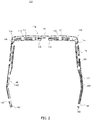
- FIG. 2 is a plan view and partial perspective view of electronic glasses 100.
- FIG. 3 is a partial perspective view of electronic glasses 100 as viewed from the right side.
- control unit 150, wiring 151, and coil spring 200 housed in housing 142 of temple 140 are illustrated in the perspective state of housing 142.
- control unit 150, wiring 151, and coil spring 200 are illustrated on only the right side of temple 140 as viewed from the user of electronic glasses 100.
- Ear hooking portion 143 is formed in the vicinity of the rear end portion of temple 140.
- ear hooking portion 143 is integrally molded as a part of housing 142 of temple 140, the present invention is not limited thereto.
- Ear hooking portion 143 may be formed separately from the same or different material as housing 142, and may be attached to the rear end portion of temple 140.
- contacted portion 144 is provided in the vicinity of the front end of temple 140.
- Contacted portion 144 is, for example, a portion that may be contacted by an object such as a finger of the user to operate electronic glasses 100.
- at least a part of contacted portion 144 is disposed so as to be exposed to the outside of housing 142.
- the position of contacted portion 144 is preferably a position at which the user of electronic glasses 100 can easily touch contacted portion 144. From this point of view, contacted portion 144 is disposed on the front side from the midpoint in the longitudinal direction of housing 142. Contacted portion 144 is disposed on the outer surface in housing 142 as viewed from the user of electronic glasses 100.
- contacted portion 144 is not limited in particular. In this embodiment, contacted portion 144 extends along the longitudinal direction of housing 142.
- contacted portion 144 is, for example, a capacitive touch sensor or a mechanical switch.
- a case where contacted portion 144 is the capacitive touch sensor will be described.
- the contact with contacted portion 144 of the object as a conductor is electrically transmitted to control unit 150.
- Contacted portion 144 has conductivity. Examples of materials for contacted portion 144 include gold, silver, copper, aluminum, and alloys thereof. In this case, it is preferable that the material of at least the peripheral portion (for example, temple 140) of contacted portion 144 is insulative.
- Control unit 150 is constituted by, for example, a CPU and/or the like. Control unit 150 controls the detection of a change in capacitance in contacted portion 144, and the application of a voltage to liquid crystal lens 111. When, for example, contacted portion 144 detects the contact of the object, control unit 150 performs control to apply a voltage to liquid crystal lens 111, or to stop the application of the voltage, so as to switch the refractive index of liquid crystal lens 111.
- control unit 150 when contacted portion 144 detects the contact of the object, control unit 150 performs control to display an image and/or the like, by applying a voltage to the display device and by transmitting an information signal such as a video, or performs to display the video to the display device or to switch the display of the image, by stopping the transmission of the voltage application and information signal. Control unit 150 performs operation and control of various electronic components 160 described later.
- Control unit 150 is housed in the vicinity of the front end portion of housing 142.
- Wiring 151 electrically connects control unit 150 and electronic component 160.
- Wiring 151 is, for example, a covered wire or a flexible printed circuit (FPC) covering the periphery of the conductor with an insulating covering member. As illustrated in FIGS 2 FIG. and 3, wiring 151 is housed in an insulated state within coil spring 200 formed in a cylindrical shape.
- FPC flexible printed circuit
- Electronic component 160 is a various electronic component related to the function of electronic glasses 100.
- An example of electronic component 160 is as follows: for example, an electric power source for supplying electric power to control unit 150 and liquid crystal lens 111, a memory (including a reader/writer for reading or writing external storage devices such as a flash memory and a memory card) as a storage storing various information, a wireless communication device as a communication unit for providing a wireless communication function such as a Wi-Fi, a Bluetooth (registered trademark), and a NFC (Near Field Communication), a second control unit (e.g., a device for controlling electronic devices when liquid crystal lens 111 is replaced with an electrochromic lens that changes or dims the color of the lens by applying a voltage, or when a camera described later, microphone, liquid crystal display, and/or the like are operated or controlled) performs different control from control unit 150 (a device that controls to apply the voltage to liquid crystal lens 111, or to stop the application of the voltage, so as to switch the refractive index of liquid crystal lens
- the following mode can be considered. That is, for example, the mode that control unit 150 acquires the activity state (information on the movement and position of the user obtained by the acceleration sensor, tilt sensor, GPS, and/or the like) of the user and the body state (information on the body and the health state of the user obtained by the heart rate sensor, thermometer, myoelectric sensor, and/or the like) obtained based on various sensors at all times or in a suitable time, stores them in the memory, and stores or updates the information acquired in the external network or the electronic device (a smartphone, wearable terminal, and/or the like of the user) via the wireless communication device. According to such a use mode, the usefulness of electronic glasses 100 is greatly improved.
- the electric power source which is a rechargeable battery pack detachably held at the rear end portion of housing 142 is illustrated.
- Examples of electric power source include nickel-metal hydride rechargeable battery, lithium-ion rechargeable battery, and solar cell.
- FIG. 1 to FIG. 3 although illustrating an example in which electronic component 160 as the detachable battery pack is held at the rear end of housing 142, the position where electronic component 160 is disposed is not limited in particular in the present invention.
- electric component 160 is the memory, wireless communication device, second control unit, or the like, it may be disposed at the same position as control unit 150.
- electronic component 160 is the camera, microphone, speaker, hearing aid, various sensors, or the like
- electronic component 160 may be disposed at the position corresponding to each purpose.
- the camera or microphone may be disposed in a part of front 130
- the speaker or hearing aid may be disposed in a part of ear hooking portion 143, and/or the like.
- Coil spring 200 is a spring formed in a hollow tube shape, and, for example, is formed in a cylindrical shape.
- Coil spring 200 is an example of the hollow member of the present invention.
- coil spring 200 is, for example, disposed from the rear side of control unit 150 to the rear end portion of housing 142, i.e. the tip portion of ear hooking portion 143, in the interior of housing 142.
- wiring 151 is housed in a state of being insulated from coil spring 200 within coil spring 200. With this configuration, wiring 151 for connecting control unit 150 housed in the vicinity of the front end portion of housing 142 and electronic component 160 attached to the rear end portion of and housing 142 is physically protected by coil spring 200.
- Coil spring 200 should be disposed within housing 142, at least, in a portion of the region of temple 140 of electronic glasses 100 to be bent for fitting to the user.
- Coil spring 200 is formed of metal. By disposing coil spring 200 within housing 142, the strength of temple 140 is ensured.
- Coil spring 200 also has elasticity. In the case adjustment (fitting) for fitting ear hooking portion 143 to the ear shell is required, coil spring 200 is easily elastically deformed following housing 142.
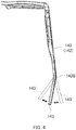
- FIG. 4 is a diagram for explaining a change in the position of ear hooking portion 143 in the case that a force is applied to ear hooking portion 143 from the outside for fitting ear hooking portion 143.
- FIG. 4 is a plan view of electronic glasses 100. As illustrated in FIG. 4 , during fitting of ear hooking portion 143, ear hooking portion 143 is deformed inwardly or outwardly in the plan view of electronic glasses 100. This can adjust so-called holding angle suitably.
- Coil spring 200 is easily elastically deformed following the deformed ear hooking portion 143.
- the presence of coil spring 200 does not easily hinder the fitting of ear hooking portion 143, and the fitting of ear hooking portion 143 can be suitably performed. Since the deformation of coil spring 200 is an elastic deformation, the bending habit does not remain even if the fitting of ear hooking portion 143 is performed a plurality of times, a situation that affects the outer shape of temple 140 by bending habit is avoided.
- FIG. 4 exemplifies a case where the holding angle is adjusted by deforming ear hooking portion 143 outward or inward when viewed from the user, in the plan view of electronic glasses 100, the present invention is not limited to this.
- so-called drop angle may be adjusted by deforming temple 140 upward or downward. Both of the holding angle and the drop angle may be adjusted simultaneously.
- housing 142 in which coil spring 200 is disposed inside As an example of a manufacturing method of housing 142 in which coil spring 200 is disposed inside, for example, insert molding can be given. By inserting coil spring 200 in advance into a mold (not illustrated) formed in accordance with the outer dimensions of housing 142 and molding by injecting a material into the periphery thereof, housing 142 in which coil spring 200 is disposed inside can be manufactured.
- electronic glasses 100 includes lens 110 with liquid crystal lens 111, temple 140 which holds lens 110 and is formed hollow, control unit 150 for controlling liquid crystal lens 111, electronic component 160 which is electrically connected to control unit 150 via wiring 151, and coil spring 200 which is disposed within temple 140 in a state of housing wiring 151 therein, and deforms elastically following the deformation of ear hooking portion 143 when ear hooking portion 143 is deformed for fitting.
- coil spring 200 elastically deforms following housing 140, so that it is possible to perform the fitting of ear hooking portion 143 preferably. Even if the fitting of ear hooking portion 143 is performed a plurality of times, bending habit does not remain because the deformation of coil spring 200 is an elastic deformation, a situation that affects the outer shape of temple 140 by bending habit is avoided.
- coil spring 200 is illustrated as an example of a hollow member for ensuring the strength of temple 140, protecting wiring 151, and fitting ear hooking portion 143 preferably, the present invention is not limited to this.
- a flexible tube may be adopted in which an annular member made of a metal or a resin of which cross section is formed in an S-shaped, a metal plate or resin plate is processed into a wave shape in the cross section, or a metal tube or resin tube is processed into a bellows shape.
- a flexible tube being formed of a thin metal plate or thin resin plate in a tube shape and having gaps of a predetermined width along the longitudinal direction may be disposed within temple 140.
- the hollow member for example, a material other than metal, such as a pipe-shaped resin, may be used. In this case, the hollow member may not have elasticity. In the case that the material other than metal such as resin is used as the hollow member, although the same material as that of temple 140 may be used, for example, a material having a physical property different from that of temple 140 may be used. In this case, for example, by using a resin material having a higher flexural modulus or Young's modulus than the resin material of temple 140 for the hollow member, it is possible to improve the stability of the fitting. By using a resin material having a lower flexural modulus or Young's modulus than the resin material of temple 140 for the hollow member, the ease of fitting can be improved.
- FIG. 5A to FIG. 5E are diagrams illustrating a configuration for ensuring the strength of temple 140, protecting wiring 151, and fitting ear hooking portion 143 preferably, including coil spring 200 of the embodiment described above.
- FIG. 5A is a perspective view illustrating coil spring 200.
- FIG. 5B is a perspective view of a flexible tube.
- FIG. 5C is a cross-sectional view of a flexible tube connecting the metal annular member of which cross section is formed in an S-shape.
- FIG. 5D is a cross-sectional view of a flexible tube in which a metal plate or resin plate is processed into a wave shape in the cross section (accordions type, i.e., bellows).
- 5E is a side view of a flexible tube which is a member made by forming a thin metal plate in a tube shape and have gaps (slits)of a predetermined width along the longitudinal axis.
- Electronic glasses 100 can ensure the strength of temple 140, protect wiring 151, and fit ear hooking portion 143 preferably, by using any of the configurations illustrated in FIG. 5A to FIG. 5E .
- a coaxial cable may be adopted as an example of a mode in which the flexible tube and wiring 151 are closely adhered to or integrally formed with each other.
- coil spring 200 is disposed from the rear side of control unit 150 to the rear end portion of housing 142, i.e. the tip portion of ear hooking portion 143.
- the present invention is not limited to this.
- coil spring 200 when the deformation is performed in the rotational direction of which fulcrum is a part of temple 140 during fitting of ear hooking portion 143, coil spring 200 should be disposed at a point serving as the fulcrum.
- the fulcrum of deformation of ear hooking portion 143 is the base of ear hooking portion 143, i.e. the vicinity of the position where ear hooking portion 143 begins to bend in accordance with the shape of ear shell of the user (bent portion 143B illustrated in FIG. 4 ).
- a metal pipe (not illustrated) may be disposed inside at other portions of temple 140.
- a mode that coil spring 200 and the metal pipe is connected can be adopted.
- the strength of temple 140 can be ensured more preferably, and wiring 151 can be protected more preferably.
- fitting of ear hooking portion 143 can be performed preferably, sufficient strength of temple 140 can be ensured, and wiring 151 can be physically protected. Even if the fitting is performed a plurality of times, a situation in which the external shape of temple 140 is affected by the bending habit is avoided.
- coil spring 200 is disposed within temple 140 for the purpose of fitting ear hooking portion 143 preferably.
- the present invention is not limited to this.
- Coil spring 200 may be configured to perform fitting of not only ear hooking portion 143 but entire temple 140. In this case, it is desirable that coil spring 200 is disposed at a place of temple 140 which becomes a fulcrum of deformation at least of a part of which adjustment is required.
- Coil spring 200 may also be disposed in other than temple 140 of frame 120. Coil spring 200 may be disposed within bridge 132, for example. With this configuration, in a plan view of electronic glasses 100, it is possible to deform such as to change the angle formed by right and left rims 131 connected by bridge 132. As a result, it possible to perform fitting so as to improve the appearance and the comfort of wearing of electronic glasses 100.
- wiring 151 is housed within coil spring 200 formed in a tube shape, and control unit 150 is not housed.
- the present invention is not limited to this. If the outer dimensions of housing 142 is allowed in designing, control unit 150 may be housed within coil spring 200. In this case, it is more preferable because control unit 150 which is for example a circuit board can be physically protected by coil spring 200.
- control unit 150, wiring 151, and coil spring 200 are illustrated only in temple 140 of the right side as viewed from the user of electronic glasses 100.
- a similar configuration may be disposed in temple 140 on the left side also.
- coil spring 200 may be disposed along the longitudinal direction of temple 140 entirely.
- the present invention is suitable as an eyewear with a lens having an electric element.
Landscapes
- Physics & Mathematics (AREA)
- Health & Medical Sciences (AREA)
- General Physics & Mathematics (AREA)
- Optics & Photonics (AREA)
- Ophthalmology & Optometry (AREA)
- Nonlinear Science (AREA)
- General Health & Medical Sciences (AREA)
- Acoustics & Sound (AREA)
- Otolaryngology (AREA)
- Eyeglasses (AREA)
- Liquid Crystal (AREA)
Abstract
Description
- The present invention relates to eyewear comprising a lens having an electrical element.
- When wearing eyewear such as glasses or sunglasses, fitting (position adjustment) of each part of the frame is important for the user to obtain a good feeling of wearing. In order to improve the feeling of wearing, for example, PTL 1 discloses a technique that can easily adjust the angle of a modern (a tip portion of a temple) which is a part of a frame.
- In PTL 1, a hollow cylindrical portion is formed at the rear end portion of the temple, a coil spring is provided in the hollow cylindrical portion, a coupling shaft portion is of the modern is inserted into the hollow cylindrical portion of the temple in a state that both ends of the coil spring are connected to the bottom portion of the hollow cylindrical portion and the coupling shaft portion of the modern. With such a configuration, the position of the modern can be freely adjusted in the direction around the temple axis.
- PTL1 Japanese Patent Application Laid-Open No.
2009-92946 - In recent years, eyewear equipped with a lens having an electric element has been used in various applications. In such eyewear, for example, the refractive index, color, polarization state and/or the like of the lens can be changed by controlling the electric element. In the eyewear equipped with the lens having such the electrical element, it is necessary to form the hollow frame with, for example, a resin and/or the like to pass wiring for supplying electric power to the electrical element. Although the strength of the frame formed hollow by resin and/or the like is low, the strength can be ensured by disposing a hollow member such as a metal pipe in the frame, for example. The wiring can be protected by passing the wiring in the metal pipe.
- In the eyewear equipped with the lens having such the electric element, in the case that the fitting of each portion of the frame is required, fitting is performed by applying heat to softening the resin frame, and by deforming by applying a force to the softened frame. There is a problem that when the metal pipe is disposed inside the frame, it is necessary to deform the metal pipe together with the frame, the time and effort required for fitting is increased. In the case that fitting is necessary multiple times, bending habits caused by deforming multiple times in the metal pipe may occur to adversely affect the outer shape of the frame.
- There is a demand for a configuration so that fitting of the frame can be performed preferably in the eyewear with the lens having the electric element.
- In view of the above circumstances, it is an object of the present invention to provide an eyewear with a lens having an electric element, in which fitting of a frame can be preferably performed.
- An eyewear according to the present invention includes: a lens including an electrical element; a frame which holds the lens and is partially formed hollow; a control unit for controlling the electrical element; an electronic component electrically connected to the control unit via wiring; and a hollow member which is disposed within the frame in a state of housing the wiring therein and deforms by following deformation of the frame.
- An eyewear according to the present invention includes: a lens including an electrical element; a frame which holds the lens and is partially formed hollow; a control unit for controlling the electrical element; an electronic component electrically connected to the control unit via wiring; and a flexible tube which is disposed within the frame in a state of housing the wiring therein and deforms by following deformation of the frame.
- According to the present invention, it is possible to preferably perform fitting of a frame in an eyewear with a lens having an electric element.
-
-
FIG. 1A is a perspective view illustrating an example of a configuration of electronic glasses according to the present embodiment; -
FIG. 2 is a plan view and partial perspective view of electronic glasses; -
FIG. 3 is a partial perspective view of electronic glasses as viewed from the right side; -
FIG. 4 is a diagram for explaining a change in the position of ear hooking portion in the case that a force is applied to ear hooking portion from the outside for fitting ear hooking portion; -
FIG. 5A is a perspective view illustrating coil spring; -
FIG. 5B is a perspective view of a flexible tube; -
FIG. 5C is a cross-sectional view of a flexible tube connecting the metal annular member of which cross section is formed in an S-shape; -
FIG. 5D is a cross-sectional view of a flexible tube in which a metal plate or resin plate is processed into a wave shape in the cross section (accordions type, i.e., bellows); and -
FIG. 5E is a side view of a flexible tube which is a member made by forming a thin metal plate in a tube shape and have gaps (slits)of a predetermined width along the longitudinal axis. - Hereinafter, eyewear according to an embodiment of the present invention will be described with reference to the drawings.
- In the present invention, the term "eyewear" means an appliance used by being worn on the eyes for visual acuity correction, eye protection, viewing of images, and/or the like. In the present invention, the term "eyewear" includes a VR glass for experiencing a virtual space(VR)/augmented reality (AR), a smart glass/headset for displaying images, and/or the like, in addition to glasses/sunglasses for visual acuity correction and/or the like. In the following description, as an example of eyewear, an electron glasses with a lens including an electroactive region whose optical properties can be changed by electrical control will be described.
-
FIG. 1 is a perspective view illustrating an example of a configuration ofelectronic glasses 100 according to the present embodiment.Electronic glasses 100 have a pair oflenses 110,frame 120, andelectronic components 160.Frame 120 hasfront 130 and a pair oftemples 140. In the following description, the portion in whichfront 130 is disposed will be described as the front ofelectronic glasses 100. - A pair of
lenses 110 are formed so as to be symmetrical when viewed from the front ofelectronic glasses 100, and have the same components to each other. -
Lens 110 hasliquid crystal lens 111 and a pair of electrodes (not illustrated).Liquid crystal lens 111 has a multilayer structure, at least a pair of conductive layers sandwiching the liquid crystal layer (not illustrated) from the front and rear (not illustrated). A pair of conductive layers are connected to the electrodes, respectively. When a voltage is applied between a pair of conductive layers, the liquid crystal layer is activated and the refractive index ofliquid crystal lens 111 is changed. As the electrode, a transparent electrode such as ITO is used.Liquid crystal lens 111 is an example of the electric element of the present invention, and may be a display device and/or the like. -
Lens 110 is formed so as to have a shape suited to the shape ofrim 131 described later by being cut out from the lens blank. - As illustrated in
FIG. 1 ,front 130 holds a pair oflenses 110.Front 130 has a pair ofrims 131 supporting a pair oflenses 110 respectively, andbridge 132 connecting the pair ofrims 131 to each other. The shape ofrim 131 is shaped to correspond to the shape oflens 110. Bridge 132 has a pair ofnasal pads 133 that can contact the user's nose. Although not illustrated in particular, wiring for electrically connecting the electrode oflenses 110 andcontrol unit 150 to be described later are disposed withinfront 130. - The material of
front 130configuring frame 120 is not limited in particular, a material having thermoplasticity and capable of adjusting the position and shape of each portion if necessary is preferred. As the material offront 130, a known material which is used as a material of the front of the glasses may be used. Examples of the material offront 130 include polyamide, acetate, carbon, celluloid, polyetherimide, and urethane. -
Front 130 has closingblocks 134 near both ends thereof.Closing block 134 is a portion extending leftward or rightward and rearward as viewed fromrim 131. The rearward tip portion ofclosing block 134 is connected totemple 140 byhinge 141. - The pair of right and left
temples 140 are formed so as to have a substantially left-right symmetrical outer shape atelectronic glasses 100. As illustrated inFIG. 1 ,temple 140 is rotatably connected tofront 130 athinge 141 at the front end oftemple 140. Note that the term "front" or "back" in the following description oftemple 140 means front or back in the state thattemple 140 is deployed (as illustrated inFIG. 1 to FIG. 3 ). - The material of
temple 140configuring frame 120 is not limited in particular, a material having thermoplasticity and capable of adjusting the position and shape of each portion if necessary is preferred, such as a resin. As the material oftemple 140, a known material which is used as a material of the temple of the glasses may be used, for example, the same material as the example of the material offront 130. By using a transparent or semi-transparent material as the material oftemple 140, for example, it is possible to confirm the state of the fitting and the bending state ofcoil spring 200 described later from the outside. In the state that a logo, mark, or pattern is performed oncoil spring 200, manufacturing information, product information, serial number, bar code or the like is printed, it is also possible to improve the design oftemple 140, or to utilize the traceability improvement or forgery prevention countermeasure of the product. - As illustrated in
FIG. 2 andFIG. 3 , the outer shape oftemple 140 is constituted byhousing 142.Housing 142 houses controlunit 150, wiring 151, andcoil spring 200.FIG. 2 is a plan view and partial perspective view ofelectronic glasses 100.FIG. 3 is a partial perspective view ofelectronic glasses 100 as viewed from the right side. InFIG. 2 andFIG. 3 ,control unit 150, wiring 151, andcoil spring 200 housed inhousing 142 oftemple 140 are illustrated in the perspective state ofhousing 142. InFIG. 2 ,control unit 150, wiring 151, andcoil spring 200 are illustrated on only the right side oftemple 140 as viewed from the user ofelectronic glasses 100. -
Ear hooking portion 143 is formed in the vicinity of the rear end portion oftemple 140. In this embodiment,ear hooking portion 143 is integrally molded as a part ofhousing 142 oftemple 140, the present invention is not limited thereto.Ear hooking portion 143 may be formed separately from the same or different material ashousing 142, and may be attached to the rear end portion oftemple 140. - As illustrated in
FIG. 1 andFIG. 2 , contactedportion 144 is provided in the vicinity of the front end oftemple 140. Contactedportion 144 is, for example, a portion that may be contacted by an object such as a finger of the user to operateelectronic glasses 100. As illustrated inFIG. 1 , at least a part of contactedportion 144 is disposed so as to be exposed to the outside ofhousing 142. - The position of contacted
portion 144 is preferably a position at which the user ofelectronic glasses 100 can easily touch contactedportion 144. From this point of view, contactedportion 144 is disposed on the front side from the midpoint in the longitudinal direction ofhousing 142. Contactedportion 144 is disposed on the outer surface inhousing 142 as viewed from the user ofelectronic glasses 100. - The shape of contacted
portion 144 is not limited in particular. In this embodiment, contactedportion 144 extends along the longitudinal direction ofhousing 142. - Although not limited in particular, contacted
portion 144 is, for example, a capacitive touch sensor or a mechanical switch. In this embodiment, as an example, a case where contactedportion 144 is the capacitive touch sensor will be described. In this case, the contact with contactedportion 144 of the object as a conductor is electrically transmitted to controlunit 150. Contactedportion 144 has conductivity. Examples of materials for contactedportion 144 include gold, silver, copper, aluminum, and alloys thereof. In this case, it is preferable that the material of at least the peripheral portion (for example, temple 140) of contactedportion 144 is insulative. -
Control unit 150 is constituted by, for example, a CPU and/or the like.Control unit 150 controls the detection of a change in capacitance in contactedportion 144, and the application of a voltage toliquid crystal lens 111. When, for example, contactedportion 144 detects the contact of the object,control unit 150 performs control to apply a voltage toliquid crystal lens 111, or to stop the application of the voltage, so as to switch the refractive index ofliquid crystal lens 111. For example, in the case that the electrical element of the present invention is a display device (not illustrated), when contactedportion 144 detects the contact of the object,control unit 150 performs control to display an image and/or the like, by applying a voltage to the display device and by transmitting an information signal such as a video, or performs to display the video to the display device or to switch the display of the image, by stopping the transmission of the voltage application and information signal.Control unit 150 performs operation and control of variouselectronic components 160 described later. -
Control unit 150 is housed in the vicinity of the front end portion ofhousing 142. - Wiring 151 electrically connects
control unit 150 andelectronic component 160. Wiring 151 is, for example, a covered wire or a flexible printed circuit (FPC) covering the periphery of the conductor with an insulating covering member. As illustrated inFIGS 2 FIG. and 3,wiring 151 is housed in an insulated state withincoil spring 200 formed in a cylindrical shape. -
Electronic component 160 is a various electronic component related to the function ofelectronic glasses 100. An example ofelectronic component 160 is as follows: for example, an electric power source for supplying electric power to controlunit 150 andliquid crystal lens 111, a memory (including a reader/writer for reading or writing external storage devices such as a flash memory and a memory card) as a storage storing various information, a wireless communication device as a communication unit for providing a wireless communication function such as a Wi-Fi, a Bluetooth (registered trademark), and a NFC (Near Field Communication), a second control unit (e.g., a device for controlling electronic devices whenliquid crystal lens 111 is replaced with an electrochromic lens that changes or dims the color of the lens by applying a voltage, or when a camera described later, microphone, liquid crystal display, and/or the like are operated or controlled) performs different control from control unit 150 (a device that controls to apply the voltage toliquid crystal lens 111, or to stop the application of the voltage, so as to switch the refractive index ofliquid crystal lens 111.) described above, a second contacted portion (a second touch sensor unit), a camera, a microphone, and a speaker (including a bone conduction type speaker in addition to a conventional speaker that emits sound), a hearing aid (a sound collector), and various sensors (an acceleration sensor, tilt sensor, heart rate sensor, GPS, thermometer, myoelectric sensor, and/or the like). - As a use mode of
electronic glasses 100 withelectronic component 160 exemplified as described above, for example, the following mode can be considered. That is, for example, the mode that controlunit 150 acquires the activity state (information on the movement and position of the user obtained by the acceleration sensor, tilt sensor, GPS, and/or the like) of the user and the body state (information on the body and the health state of the user obtained by the heart rate sensor, thermometer, myoelectric sensor, and/or the like) obtained based on various sensors at all times or in a suitable time, stores them in the memory, and stores or updates the information acquired in the external network or the electronic device (a smartphone, wearable terminal, and/or the like of the user) via the wireless communication device. According to such a use mode, the usefulness ofelectronic glasses 100 is greatly improved. - In
FIG. 1 to FIG. 3 , aselectronic component 160, the electric power source which is a rechargeable battery pack detachably held at the rear end portion ofhousing 142 is illustrated. Examples of electric power source include nickel-metal hydride rechargeable battery, lithium-ion rechargeable battery, and solar cell. InFIG. 1 to FIG. 3 , although illustrating an example in whichelectronic component 160 as the detachable battery pack is held at the rear end ofhousing 142, the position whereelectronic component 160 is disposed is not limited in particular in the present invention. For example, in the case thatelectric component 160 is the memory, wireless communication device, second control unit, or the like, it may be disposed at the same position ascontrol unit 150. In the case thatelectronic component 160 is the camera, microphone, speaker, hearing aid, various sensors, or the like,electronic component 160 may be disposed at the position corresponding to each purpose. For example, the camera or microphone may be disposed in a part offront 130, the speaker or hearing aid may be disposed in a part ofear hooking portion 143, and/or the like. -
Coil spring 200 is a spring formed in a hollow tube shape, and, for example, is formed in a cylindrical shape.Coil spring 200 is an example of the hollow member of the present invention. As illustrated inFIG. 2 andFIG. 3 , although not limited in particular,coil spring 200 is, for example, disposed from the rear side ofcontrol unit 150 to the rear end portion ofhousing 142, i.e. the tip portion ofear hooking portion 143, in the interior ofhousing 142. As described above, wiring 151 is housed in a state of being insulated fromcoil spring 200 withincoil spring 200. With this configuration, wiring 151 for connectingcontrol unit 150 housed in the vicinity of the front end portion ofhousing 142 andelectronic component 160 attached to the rear end portion of andhousing 142 is physically protected bycoil spring 200.Coil spring 200 should be disposed withinhousing 142, at least, in a portion of the region oftemple 140 ofelectronic glasses 100 to be bent for fitting to the user. -
Coil spring 200 is formed of metal. By disposingcoil spring 200 withinhousing 142, the strength oftemple 140 is ensured. -
Coil spring 200 also has elasticity. In the case adjustment (fitting) for fittingear hooking portion 143 to the ear shell is required,coil spring 200 is easily elastically deformed followinghousing 142. -
FIG. 4 is a diagram for explaining a change in the position ofear hooking portion 143 in the case that a force is applied toear hooking portion 143 from the outside for fittingear hooking portion 143.FIG. 4 is a plan view ofelectronic glasses 100. As illustrated inFIG. 4 , during fitting ofear hooking portion 143,ear hooking portion 143 is deformed inwardly or outwardly in the plan view ofelectronic glasses 100. This can adjust so-called holding angle suitably. -
Coil spring 200 is easily elastically deformed following the deformedear hooking portion 143. The presence ofcoil spring 200 does not easily hinder the fitting ofear hooking portion 143, and the fitting ofear hooking portion 143 can be suitably performed. Since the deformation ofcoil spring 200 is an elastic deformation, the bending habit does not remain even if the fitting ofear hooking portion 143 is performed a plurality of times, a situation that affects the outer shape oftemple 140 by bending habit is avoided. - Although
FIG. 4 exemplifies a case where the holding angle is adjusted by deformingear hooking portion 143 outward or inward when viewed from the user, in the plan view ofelectronic glasses 100, the present invention is not limited to this. For example, so-called drop angle may be adjusted by deformingtemple 140 upward or downward. Both of the holding angle and the drop angle may be adjusted simultaneously. - As an example of a manufacturing method of
housing 142 in whichcoil spring 200 is disposed inside, for example, insert molding can be given. By insertingcoil spring 200 in advance into a mold (not illustrated) formed in accordance with the outer dimensions ofhousing 142 and molding by injecting a material into the periphery thereof,housing 142 in whichcoil spring 200 is disposed inside can be manufactured. - As described above,
electronic glasses 100 according to the embodiment of the present invention includeslens 110 withliquid crystal lens 111,temple 140 which holdslens 110 and is formed hollow,control unit 150 for controllingliquid crystal lens 111,electronic component 160 which is electrically connected to controlunit 150 viawiring 151, andcoil spring 200 which is disposed withintemple 140 in a state ofhousing wiring 151 therein, and deforms elastically following the deformation ofear hooking portion 143 whenear hooking portion 143 is deformed for fitting. - With such a configuration, it is possible to protect
wiring 151 physically, and to ensure the strength oftemple 140, bycoil spring 200. When the fitting ofear hooking portion 143,coil spring 200 elastically deforms followinghousing 140, so that it is possible to perform the fitting ofear hooking portion 143 preferably. Even if the fitting ofear hooking portion 143 is performed a plurality of times, bending habit does not remain because the deformation ofcoil spring 200 is an elastic deformation, a situation that affects the outer shape oftemple 140 by bending habit is avoided. - While the embodiment of the present invention has been described above with reference to the accompanying drawings, the present invention is not limited to such example. It is obvious that various examples of variations or modifications can be conceived by the person skilled in the art within the scope of the claims, and it is understood that they belong to the technical scope of the invention of course. The components in the above embodiment may be arbitrarily combined without departing from the spirit of the invention.
- In the embodiment described above,
coil spring 200 is illustrated as an example of a hollow member for ensuring the strength oftemple 140, protectingwiring 151, and fittingear hooking portion 143 preferably, the present invention is not limited to this. For example, instead ofcoil spring 200, a flexible tube may be adopted in which an annular member made of a metal or a resin of which cross section is formed in an S-shaped, a metal plate or resin plate is processed into a wave shape in the cross section, or a metal tube or resin tube is processed into a bellows shape. Instead ofcoil spring 200, a flexible tube being formed of a thin metal plate or thin resin plate in a tube shape and having gaps of a predetermined width along the longitudinal direction may be disposed withintemple 140. Even in the case that such a member is disposed withintemple 140, it is possible to obtain the same effect as the case of employingcoil spring 200. As the hollow member, for example, a material other than metal, such as a pipe-shaped resin, may be used. In this case, the hollow member may not have elasticity. In the case that the material other than metal such as resin is used as the hollow member, although the same material as that oftemple 140 may be used, for example, a material having a physical property different from that oftemple 140 may be used. In this case, for example, by using a resin material having a higher flexural modulus or Young's modulus than the resin material oftemple 140 for the hollow member, it is possible to improve the stability of the fitting. By using a resin material having a lower flexural modulus or Young's modulus than the resin material oftemple 140 for the hollow member, the ease of fitting can be improved. -
FIG. 5A to FIG. 5E are diagrams illustrating a configuration for ensuring the strength oftemple 140, protectingwiring 151, and fittingear hooking portion 143 preferably, includingcoil spring 200 of the embodiment described above.FIG. 5A is a perspective view illustratingcoil spring 200.FIG. 5B is a perspective view of a flexible tube.FIG. 5C is a cross-sectional view of a flexible tube connecting the metal annular member of which cross section is formed in an S-shape.FIG. 5D is a cross-sectional view of a flexible tube in which a metal plate or resin plate is processed into a wave shape in the cross section (accordions type, i.e., bellows).FIG. 5E is a side view of a flexible tube which is a member made by forming a thin metal plate in a tube shape and have gaps (slits)of a predetermined width along the longitudinal axis.Electronic glasses 100 according to the embodiment of the present disclosure can ensure the strength oftemple 140, protectwiring 151, and fitear hooking portion 143 preferably, by using any of the configurations illustrated inFIG. 5A to FIG. 5E . Although not illustrated, for example, a coaxial cable may be adopted as an example of a mode in which the flexible tube andwiring 151 are closely adhered to or integrally formed with each other. - In the embodiment described above, since wiring 151 is disposed within
coil spring 200 from the viewpoint of protection ofwiring 151,coil spring 200 is disposed from the rear side ofcontrol unit 150 to the rear end portion ofhousing 142, i.e. the tip portion ofear hooking portion 143. However, the present invention is not limited to this. In the present invention, as illustrated inFIG. 4 , when the deformation is performed in the rotational direction of which fulcrum is a part oftemple 140 during fitting ofear hooking portion 143,coil spring 200 should be disposed at a point serving as the fulcrum. The fulcrum of deformation ofear hooking portion 143 is the base ofear hooking portion 143, i.e. the vicinity of the position whereear hooking portion 143 begins to bend in accordance with the shape of ear shell of the user (bent portion 143B illustrated inFIG. 4 ). - In the case where
coil spring 200 is disposed only in the vicinity ofbent portion 143B ofear hooking portion 143, for example, a metal pipe (not illustrated) may be disposed inside at other portions oftemple 140. A mode thatcoil spring 200 and the metal pipe is connected can be adopted. As a result, the strength oftemple 140 can be ensured more preferably, andwiring 151 can be protected more preferably. With such a configuration, fitting ofear hooking portion 143 can be performed preferably, sufficient strength oftemple 140 can be ensured, andwiring 151 can be physically protected. Even if the fitting is performed a plurality of times, a situation in which the external shape oftemple 140 is affected by the bending habit is avoided. - In the embodiment described above,
coil spring 200 is disposed withintemple 140 for the purpose of fittingear hooking portion 143 preferably. The present invention is not limited to this.Coil spring 200 may be configured to perform fitting of not onlyear hooking portion 143 butentire temple 140. In this case, it is desirable thatcoil spring 200 is disposed at a place oftemple 140 which becomes a fulcrum of deformation at least of a part of which adjustment is required. -
Coil spring 200 may also be disposed in other thantemple 140 offrame 120.Coil spring 200 may be disposed withinbridge 132, for example. With this configuration, in a plan view ofelectronic glasses 100, it is possible to deform such as to change the angle formed by right and leftrims 131 connected bybridge 132. As a result, it possible to perform fitting so as to improve the appearance and the comfort of wearing ofelectronic glasses 100. - In the embodiment described above, wiring 151 is housed within
coil spring 200 formed in a tube shape, andcontrol unit 150 is not housed. The present invention is not limited to this. If the outer dimensions ofhousing 142 is allowed in designing,control unit 150 may be housed withincoil spring 200. In this case, it is more preferable becausecontrol unit 150 which is for example a circuit board can be physically protected bycoil spring 200. - In the above-described embodiment, in
FIG. 2 ,control unit 150, wiring 151, andcoil spring 200 are illustrated only intemple 140 of the right side as viewed from the user ofelectronic glasses 100. In the present invention, a similar configuration may be disposed intemple 140 on the left side also. In the case that controlunit 150 is disposed only in one of the right and lefttemples 140, intemple 140 of the side in which controlunit 150 is not disposed,coil spring 200 may be disposed along the longitudinal direction oftemple 140 entirely. - This application is entitled to and claims the benefit of Japanese Patent Application No.
2018-055006 filed on March 22, 2018 - The present invention is suitable as an eyewear with a lens having an electric element.
-
- 100
- Electronic glasses
- 110
- Lens
- 111
- Liquid crystal lens
- 120
- Frame
- 130
- Front
- 131
- Rim
- 132
- Bridge
- 133
- Nasal pad
- 134
- Closing block
- 140
- Temple
- 141
- Hinge
- 142
- Housing
- 143
- Ear hooking portion
- 144
- Contacted portion
- 150
- Control unit
- 151
- Wiring
- 160
- Electronic component
- 200
- Coil spring
Claims (17)
- An eyewear, comprising:a lens including an electrical element;a frame which holds the lens and is partially formed hollow;a control unit for controlling the electrical element;an electronic component electrically connected to the control unit via wiring; anda hollow member which is disposed within the frame in a state of housing the wiring therein and deforms by following deformation of the frame.
- The eyewear according to claim 1, wherein the hollow member elastically deforms by following the deformation of the frame.
- The eyewear according to claim 1 or 2, wherein the hollow member is formed of metal.
- The eyewear according to any one of claims 1 to 3, wherein the hollow member is disposed within a temple.
- The eyewear according to claim 4, wherein:the temple includes an ear hooking portion including a bent portion, andthe hollow member is disposed at the bent portion.
- The eyewear according to claim 1, wherein the hollow member is disposed within a bridge.
- The eyewear according to any one of claims 1 to 6, wherein the hollow member is a coil spring.
- The eyewear according to claim 4 or 5, wherein the hollow member has an elastic deformation region that elastically deforms by following the deformation of the frame in a predetermined range including the bent portion of the ear hooking portion of the temple, and has an inelastic deformation region that deforms by following the deformation of the frame in a range other than the predetermined range including the bent portion of the ear hooking portion of the temple.
- The eyewear according to claim 8, wherein:the elastic deformation region is formed of a coil spring,the inelastic deformation region is formed of a metal pipe, andthe elastic deformation region and the inelastic deformation region are connected to each other.
- An eyewear, comprising:a lens including an electrical element;a frame which holds the lens and is partially formed hollow;a control unit for controlling the electrical element;an electronic component electrically connected to the control unit via wiring; anda flexible tube which is disposed within the frame in a state of housing the wiring therein and deforms by following deformation of the frame.
- The eyewear according to claim 10, wherein the flexible tube is formed by joining together metal annular members formed to have an S-shape in cross section.
- The eyewear according to claim 10, wherein the flexible tube is formed by processing a metal plate into a wave shape in cross section.
- The eyewear according to claim 10, wherein the flexible tube is formed by processing a metal tube into a bellows shape.
- The eyewear according to claim 10, wherein the flexible tube is a member formed of a thin metal plate in a tube shape and has one or more gaps of a predetermined width along the longitudinal direction.
- The eyewear according to claim 10, wherein the flexible tube is a coaxial cable.
- The eyewear according to any one of claims 1 to 15, wherein the electronic component is an electric power source for supplying electric power to the control unit.
- The eyewear according to any one of claims 1 to 16, wherein the electronic component is a sensor for acquiring body information of a user of the eyewear.
Applications Claiming Priority (2)
| Application Number | Priority Date | Filing Date | Title |
|---|---|---|---|
| JP2018055006 | 2018-03-22 | ||
| PCT/JP2019/000691 WO2019181150A1 (en) | 2018-03-22 | 2019-01-11 | Eyewear |
Publications (2)
| Publication Number | Publication Date |
|---|---|
| EP3770671A1 true EP3770671A1 (en) | 2021-01-27 |
| EP3770671A4 EP3770671A4 (en) | 2021-12-29 |
Family
ID=67986959
Family Applications (1)
| Application Number | Title | Priority Date | Filing Date |
|---|---|---|---|
| EP19770706.0A Withdrawn EP3770671A4 (en) | 2018-03-22 | 2019-01-11 | Eyewear |
Country Status (5)
| Country | Link |
|---|---|
| US (1) | US11953757B2 (en) |
| EP (1) | EP3770671A4 (en) |
| JP (1) | JP7015378B2 (en) |
| CN (1) | CN111684340A (en) |
| WO (1) | WO2019181150A1 (en) |
Cited By (2)
| Publication number | Priority date | Publication date | Assignee | Title |
|---|---|---|---|---|
| WO2025158007A1 (en) * | 2024-01-26 | 2025-07-31 | Xocchiali Ab | Electronic eyeglass set |
| EP4513255A4 (en) * | 2022-09-01 | 2025-10-08 | Huawei Tech Co Ltd | SMART GLASSES AND ELECTRONIC DEVICE |
Families Citing this family (10)
| Publication number | Priority date | Publication date | Assignee | Title |
|---|---|---|---|---|
| US11103140B2 (en) | 2015-06-14 | 2021-08-31 | Facense Ltd. | Monitoring blood sugar level with a comfortable head-mounted device |
| US11154203B2 (en) | 2015-06-14 | 2021-10-26 | Facense Ltd. | Detecting fever from images and temperatures |
| US11449826B2 (en) * | 2019-03-15 | 2022-09-20 | Hashim Muhammad SIDDIQUI | Systems and methods for autonomous inventory counting and tracking |
| WO2021084488A1 (en) * | 2019-10-31 | 2021-05-06 | Facense Ltd. | Smartglasses for detecting physiological parameters |
| JP7440721B2 (en) * | 2020-01-29 | 2024-02-29 | カール ツァイス ヴィジョン インターナショナル ゲーエムベーハー | Eyewear |
| US11604367B2 (en) * | 2020-04-08 | 2023-03-14 | Facense Ltd. | Smartglasses with bendable temples |
| EP4439239A4 (en) | 2021-12-30 | 2025-04-09 | Samsung Electronics Co., Ltd. | ELECTRONIC DEVICE COMPRISING A CONNECTION ELEMENT |
| CN114545661A (en) * | 2022-03-08 | 2022-05-27 | 西安建筑科技大学 | Glasses based on ultrasonic ranging dynamic adjustment degree |
| EP4375797A4 (en) * | 2022-10-11 | 2026-01-14 | Samsung Electronics Co Ltd | PORTABLE DEVICE WITH SPEAKER |
| CN223155313U (en) * | 2024-09-09 | 2025-07-25 | 华为技术有限公司 | Intelligent glasses |
Family Cites Families (16)
| Publication number | Priority date | Publication date | Assignee | Title |
|---|---|---|---|---|
| US3825700A (en) * | 1973-03-02 | 1974-07-23 | Sonotone Corp | Articulated hearing aid temple and behind-the-ear hearing aid element |
| JPS5867313U (en) * | 1981-10-29 | 1983-05-07 | 株式会社 佐々木セルロイド工業所 | tendrils in glasses |
| JPS58128412U (en) * | 1982-02-22 | 1983-08-31 | 株式会社 佐々木セルロイド工業所 | eyeglass frame |
| JPH0545637U (en) * | 1991-11-25 | 1993-06-18 | 株式会社大日工業 | Eyeglass frame ear hook device |
| US5781272A (en) * | 1997-06-06 | 1998-07-14 | Safety+Plus, Inc. | Eyesight protection apparatus with attached earplugs |
| US6513926B1 (en) * | 2002-07-30 | 2003-02-04 | Umeda Inc. | Double-foldable eyeglasses |
| JP2008009044A (en) * | 2006-06-28 | 2008-01-17 | Kiyohiko Tsuji | Eyeglass cell (temple and modern designs) |
| JP4768571B2 (en) * | 2006-10-10 | 2011-09-07 | Hoya株式会社 | Eyeglass frames |
| JP2009092946A (en) | 2007-10-09 | 2009-04-30 | Nojiri Optical Co Ltd | Spring-biasing type tip angle adjusting mechanism for eyeglasses frame |
| US20110088820A1 (en) * | 2009-10-16 | 2011-04-21 | Eli Khuri | Spectacles temple protector |
| US9442305B2 (en) * | 2012-06-14 | 2016-09-13 | Mitsui Chemicals, Inc. | Electronic eyeglasses and methods of manufacturing |
| FR3027412A1 (en) * | 2014-10-21 | 2016-04-22 | Arch | BRANCH FOR EYEWEAR. |
| JP2017134100A (en) | 2016-01-25 | 2017-08-03 | 富士フイルム株式会社 | Spectacles with air delivery function |
| JP2018055006A (en) | 2016-09-30 | 2018-04-05 | 株式会社沖データ | Fixing apparatus and image forming apparatus |
| US20190041666A1 (en) * | 2017-12-28 | 2019-02-07 | Nicolas Abele | Electronically reinforced head-wearable apparatus and related methods |
| EP3750028B1 (en) * | 2018-02-09 | 2022-10-19 | Pupil Labs GmbH | Devices, systems and methods for predicting gaze-related parameters |
-
2019
- 2019-01-11 EP EP19770706.0A patent/EP3770671A4/en not_active Withdrawn
- 2019-01-11 CN CN201980011661.5A patent/CN111684340A/en active Pending
- 2019-01-11 JP JP2020507369A patent/JP7015378B2/en active Active
- 2019-01-11 US US17/040,061 patent/US11953757B2/en active Active
- 2019-01-11 WO PCT/JP2019/000691 patent/WO2019181150A1/en not_active Ceased
Cited By (2)
| Publication number | Priority date | Publication date | Assignee | Title |
|---|---|---|---|---|
| EP4513255A4 (en) * | 2022-09-01 | 2025-10-08 | Huawei Tech Co Ltd | SMART GLASSES AND ELECTRONIC DEVICE |
| WO2025158007A1 (en) * | 2024-01-26 | 2025-07-31 | Xocchiali Ab | Electronic eyeglass set |
Also Published As
| Publication number | Publication date |
|---|---|
| US20210026157A1 (en) | 2021-01-28 |
| JPWO2019181150A1 (en) | 2021-01-07 |
| WO2019181150A1 (en) | 2019-09-26 |
| JP7015378B2 (en) | 2022-02-02 |
| EP3770671A4 (en) | 2021-12-29 |
| US11953757B2 (en) | 2024-04-09 |
| CN111684340A (en) | 2020-09-18 |
Similar Documents
| Publication | Publication Date | Title |
|---|---|---|
| US11953757B2 (en) | Eyewear | |
| JP6513195B2 (en) | Glasses-type electronic equipment | |
| EP2942931B1 (en) | Mobile terminal with eyeglass display | |
| JP6383490B2 (en) | Eyeglass-type electronic equipment | |
| TWI607240B (en) | Eyeglass frame with input and output functionality | |
| TW201227046A (en) | Electro-active spectacle frames | |
| JP2007304587A (en) | Spectacle frame bridge housing electronic apparatus for electro-active spectacle lenses | |
| EP3751333A1 (en) | Eyewear system | |
| JP6896086B2 (en) | Eyewear | |
| KR20220017272A (en) | Wearable electronic device | |
| CN115407505A (en) | Mirror leg and intelligent glasses | |
| EP3754675B1 (en) | Wireless power transmission system comprising transparent heating element, and head mounted device including same | |
| US11294199B2 (en) | Eyewear | |
| CN111670404B (en) | Lens unit for optometry and lens assembly for optometry | |
| CN113474717A (en) | Contact lens, contact lens pair and wearing device | |
| WO2015170662A1 (en) | Human body characteristic detection device and glasses-type electronic device |
Legal Events
| Date | Code | Title | Description |
|---|---|---|---|
| STAA | Information on the status of an ep patent application or granted ep patent |
Free format text: STATUS: THE INTERNATIONAL PUBLICATION HAS BEEN MADE |
|
| PUAI | Public reference made under article 153(3) epc to a published international application that has entered the european phase |
Free format text: ORIGINAL CODE: 0009012 |
|
| STAA | Information on the status of an ep patent application or granted ep patent |
Free format text: STATUS: REQUEST FOR EXAMINATION WAS MADE |
|
| 17P | Request for examination filed |
Effective date: 20200922 |
|
| AK | Designated contracting states |
Kind code of ref document: A1 Designated state(s): AL AT BE BG CH CY CZ DE DK EE ES FI FR GB GR HR HU IE IS IT LI LT LU LV MC MK MT NL NO PL PT RO RS SE SI SK SM TR |
|
| AX | Request for extension of the european patent |
Extension state: BA ME |
|
| DAV | Request for validation of the european patent (deleted) | ||
| DAX | Request for extension of the european patent (deleted) | ||
| A4 | Supplementary search report drawn up and despatched |
Effective date: 20211129 |
|
| RIC1 | Information provided on ipc code assigned before grant |
Ipc: G02F 1/1333 20060101ALI20211123BHEP Ipc: G02F 1/133 20060101ALI20211123BHEP Ipc: G02C 11/00 20060101ALI20211123BHEP Ipc: G02C 11/06 20060101ALI20211123BHEP Ipc: G02C 5/20 20060101ALI20211123BHEP Ipc: G02C 5/14 20060101ALI20211123BHEP Ipc: G02F 1/13 20060101ALI20211123BHEP Ipc: G02C 7/02 20060101ALI20211123BHEP Ipc: G02C 5/06 20060101ALI20211123BHEP Ipc: G02C 5/16 20060101AFI20211123BHEP |
|
| STAA | Information on the status of an ep patent application or granted ep patent |
Free format text: STATUS: THE APPLICATION IS DEEMED TO BE WITHDRAWN |
|
| 18D | Application deemed to be withdrawn |
Effective date: 20220628 |