EP3770569B1 - Method using dry block temperature calibrator to calibrate short temperature measuring apparatus - Google Patents
Method using dry block temperature calibrator to calibrate short temperature measuring apparatus Download PDFInfo
- Publication number
- EP3770569B1 EP3770569B1 EP19772266.3A EP19772266A EP3770569B1 EP 3770569 B1 EP3770569 B1 EP 3770569B1 EP 19772266 A EP19772266 A EP 19772266A EP 3770569 B1 EP3770569 B1 EP 3770569B1
- Authority
- EP
- European Patent Office
- Prior art keywords
- temperature
- temperature measuring
- calibrator
- measuring device
- heat soaking
- Prior art date
- Legal status (The legal status is an assumption and is not a legal conclusion. Google has not performed a legal analysis and makes no representation as to the accuracy of the status listed.)
- Active
Links
Images

Classifications
-
- G—PHYSICS
- G01—MEASURING; TESTING
- G01K—MEASURING TEMPERATURE; MEASURING QUANTITY OF HEAT; THERMALLY-SENSITIVE ELEMENTS NOT OTHERWISE PROVIDED FOR
- G01K15/00—Testing or calibrating of thermometers
- G01K15/005—Calibration
-
- F—MECHANICAL ENGINEERING; LIGHTING; HEATING; WEAPONS; BLASTING
- F27—FURNACES; KILNS; OVENS; RETORTS
- F27D—DETAILS OR ACCESSORIES OF FURNACES, KILNS, OVENS OR RETORTS, IN SO FAR AS THEY ARE OF KINDS OCCURRING IN MORE THAN ONE KIND OF FURNACE
- F27D21/00—Arrangement of monitoring devices; Arrangement of safety devices
- F27D21/0014—Devices for monitoring temperature
-
- G—PHYSICS
- G01—MEASURING; TESTING
- G01K—MEASURING TEMPERATURE; MEASURING QUANTITY OF HEAT; THERMALLY-SENSITIVE ELEMENTS NOT OTHERWISE PROVIDED FOR
- G01K7/00—Measuring temperature based on the use of electric or magnetic elements directly sensitive to heat ; Power supply therefor, e.g. using thermoelectric elements
- G01K7/16—Measuring temperature based on the use of electric or magnetic elements directly sensitive to heat ; Power supply therefor, e.g. using thermoelectric elements using resistive elements
-
- F—MECHANICAL ENGINEERING; LIGHTING; HEATING; WEAPONS; BLASTING
- F27—FURNACES; KILNS; OVENS; RETORTS
- F27D—DETAILS OR ACCESSORIES OF FURNACES, KILNS, OVENS OR RETORTS, IN SO FAR AS THEY ARE OF KINDS OCCURRING IN MORE THAN ONE KIND OF FURNACE
- F27D99/00—Subject matter not provided for in other groups of this subclass
Definitions
- the invention belongs to the field of temperature calibration, specifically relates to a method for calibrating short temperature measuring device using a dry body temperature calibrator.
- DE 20 2010 013086 U1 discloses a method for calibrating a measuring device using a dry body temperature calibrator, wherein a heat soaking block is placed in a furnace of the dry body calibrator and a first temperature measuring hole and a second temperature measuring hole are provided the heat soaking block, the method comprising a step of inserting a probe of a first standard temperature sensor and a probe of the temperature measuring device into the first temperature measuring hole of the heat soaking block in the dry temperature calibrator, respectively, keeping temperature of the first standard temperature sensor at temperature T1, and obtaining measured temperature T1' of the temperature measuring device.
- thermocouple sensors such as short platinum resistance or thermocouple sensors, short or right-angle thermistor temperature sensors, etc.
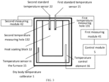
- FIG. 1 due to the short length of this short temperature measuring device, the horizontal distance between the temperature measuring device to be calibrated 3 and the temperature sensing element 14 of the temperature sensor in the furnace 15 is large. The error would be large if the measured temperature by the temperature sensor in the furnace 15 is used as the actual temperature to calibrate the temperature measuring device to be calibrated 3.
- the invention provides a method for calibrating short temperature measuring device using a dry body temperature calibrator, which can calibrate a short temperature measuring device more accurately.
- the present invention employs the following technical solutions.
- the invention provides a method for calibrating a short temperature measuring device 3 using a dry body temperature calibrator 1, i.e. for calibrating the temperature measuring device to be calibrated 3, wherein a heat soaking block 12 is placed in a furnace of the dry body temperature calibrator 1 and a first temperature measuring hole 131 and a second temperature measuring hole 132 are provided in the heat soaking block 12, the method comprising the following steps:
- the method further comprises after Step S4: Step S5, keeping temperature of the first standard temperature sensor 21 at T2, T3, T4, ..., Tn respectively after T1, and repeating Steps S2 to S4 to calibrate the short temperature measuring device 3 at multiple temperature points, wherein the measured temperatures of the short temperature measuring device 3 are T1', T2', T3', T4', ..., Tn' respectively and the calculated actual temperatures are T2", T3", T4", ..., Tn" respectively.
- the first standard temperature sensor 21 is a thermal resistance.
- depth of the first temperature measuring hole 131 and/or the second temperature measuring hole 132 of the heat soaking block 12 is close to length of the short temperature measuring device 3.
- the first standard temperature sensor 21 is electrically connected to a temperature control element 16 of the dry body temperature calibrator 1 through a first measuring module 41 and a control module 5 in sequence, so as to form a closed-loop temperature feedback control loop.
- the first measuring module 41 and the control module 5 are integrated into one measurement control module.
- the step for obtaining the temperature field model library comprising the following steps:
- the method further comprises after the Step S12: Step S13, replacing the heat soaking block 12 in the dry body temperature calibrator 1 with other types of heat soaking blocks, repeating Steps S11 to S12 to establish temperature field models of a plurality of heat soaking blocks 12 in the dry body temperature calibrator 1, and establishing a temperature field model library for a plurality of heat soaking blocks 12 in the dry body temperature calibrator 1 and storing it in the memory of the dry body temperature calibrator 1.
- the short temperature measuring device 3 and the second standard temperature sensor 22 are electrically connected to a second measuring module 42 independent of the first measuring module 41.
- depths of the temperature measuring holes of the heat soaking block 12 are less than 2/3 of height of the heat soaking block 12.
- a method for calibrating a short temperature measuring device using a dry body temperature calibrator comprises obtaining the temperature difference between the first temperature measuring hole and the second temperature measuring hole when the first temperature measuring hole is at a specific temperature, and calibrating the temperature value measured by the short temperature measuring device in the second temperature measuring hole using the temperature difference when the first temperature measuring hole is at the same specific temperature, so as to calibrate the temperature value measured by the short temperature measuring device more accurately.
- the present invention provides a method for calibrating a short temperature measuring device using a dry body temperature calibrator.
- the method includes creating a temperature field model library of a plurality of heat soaking blocks applicable for the dry body temperature calibrator by calculating the temperature difference between a probe of a temperature measuring device to be calibrated and a probe of a standard temperature measuring device which are placed in two temperature measuring holes, respectively.
- the short temperature measuring device to be calibrated 3 of this embodiment is an element or device with a temperature measuring function, including but not limited to thermal resistance, thermocouple, temperature switch, temperature transducer, and the like.
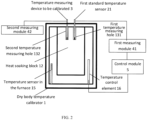
- This embodiment provides a method for calibrating a short temperature measuring device using the dry body temperature calibrator shown in FIG. 2 in order to calibrate a short temperature measuring device to be calibrated 3.
- a heat soaking block 12 is placed in the furnace of the dry body temperature calibrator 1.
- Two temperature measuring holes which are a first temperature measuring hole 131 and a second temperature measuring hole 132 respectively are provided in the heat soaking block 12. The method includes the following steps:
- keeping the temperature of the first standard temperature sensor 21 at T1 may include keeping the temperature of the probe of the first standard temperature sensor 21 at T1 by means of observing the measurement result of the first standard temperature sensor 21 continuously. This can be achieved by a temperature control element 16 at the bottom.
- the method further includes after Step S4: Step S5, keeping temperature of the first standard temperature sensor 21 at T2, T3, T4, ..., Tn respectively after T1, and repeating Steps S2 to S4 to calibrate the temperature measuring device to be calibrated 3 at multiple temperature points, wherein the measured temperatures of the temperature measuring device to be calibrated 3 are T1', T2', T3', T4', ..., Tn' respectively and the calculated actual temperatures are T2", T3", T4", ..., Tn" respectively.
- the first standard temperature sensor 21 is a thermal resistance.
- depth of the first temperature measuring hole 131 and/or the second temperature measuring hole 132 of the heat soaking block 12 is close to length of the temperature measuring device to be calibrated 3.
- the depth of the first temperature measuring hole 131 and/or the second temperature measuring hole 132 may be provided to be equal to or less than the length of the temperature measuring device to be calibrated 3.
- the first standard temperature sensor 21 is electrically connected to a temperature control element 16 of the dry body temperature calibrator 1 through a first measuring module 41 and a control module 5 in sequence, so as to form a closed-loop temperature feedback control loop.
- the first measuring module 41 and the control module 5 are integrated into one measurement control module.
- the step for obtaining the temperature field model library comprising the following steps:
- the method further includes after step S12: Step S13, replacing the heat soaking block 12 in the dry body temperature calibrator 1 with other types of heat soaking blocks, repeating Steps S11 to S12 to establish temperature field models of a plurality of heat soaking blocks 12 in the dry body temperature calibrator 1, and establishing a temperature field model library for a plurality of heat soaking blocks 12 in the dry body temperature calibrator 1 and storing it in the memory of the dry body temperature calibrator 1.
- the temperature measuring device to be calibrated 3 and the second standard temperature sensor 22 are electrically connected to a second measuring module 42 that is independent of the first measuring module 41.
- depths of the temperature measuring holes of the heat soaking block 12 is less than 2/3 of the height of the heat soaking block 12.
- the method for calibrating a short temperature measuring device using a dry body temperature calibrator in this embodiment includes obtaining the temperature difference between the first temperature measuring hole and the second temperature measuring hole when the first temperature measuring hole is kept at a specific temperature, and calibrating the temperature value measured by the short temperature measuring device in the second temperature measuring hole by means of the temperature difference when the first temperature measuring hole is at the same specific temperature, so as to calibrate the temperature value measured by the short temperature measuring device more accurately.
- the short temperature measuring device to be calibrated 3 described in FIG. 2 is an element or device with a temperature measuring function, including but not limited to thermal resistance, thermocouple, temperature switch, temperature transducer, and the like.
- This embodiment provides a method for calibrating short temperature measuring device using a dry body temperature calibrator in order to overcome the defect that the prior art cannot accurately calibrate short temperature measuring device. As shown in FIG. 2 , the method includes the following steps:
- both the first standard temperature sensor 21 and the temperature measuring device to be calibrated 3 may be thermocouples or thermal resistors, and the first standard temperature sensor 21 and the temperature measuring device to be calibrated 3 are both short temperature measuring devices.
- the type of the heat soaking block 12 is selected according to the specific lengths of the first standard temperature sensor 21 and the temperature measuring device to be calibrated 3.
- the heat soaking block 12 having temperature measuring hole with the closest depth to the length of the temperature measuring device to be calibrated 3 is selected. Since the first standard temperature sensor 21 and the temperature measuring device to be calibrated 3 are both short temperature measuring devices and the depth of the temperature measuring hole 13 of the heat soaking block 12 is small, the horizontal temperature field in the heat soaking block 12 is not even. There is a temperature difference ⁇ T between the actual temperatures in the two temperature measuring holes.
- the first standard temperature sensor 21 is connected to the temperature control element 16 of the dry body temperature calibrator 1 through the first measuring module 41 and the control module 5 in sequence to form a closed-loop temperature feedback control loop.
- the first measuring module 41 is used to measure the temperature of the probe of the first standard temperature sensor 21 (that is, obtained by measuring the temperature in the first temperature measuring hole 131).
- the output signal of the control module 5 is transmitted to the temperature control element 16 of the dry body temperature calibrator 1 in order to control the power output by the temperature control element of the dry body temperature calibrator 1, and further control the temperature in the first temperature measuring hole 131 of the dry body temperature calibrator 1.
- the control module 5 generates a heating power signal for controlling the dry body temperature calibrator 1 according to the temperature result measured by the first measuring module 41, so that the temperature at the first standard temperature sensor 21 is kept at a set value, i.e. T1.
- the first measuring module 41 and the control module 5 may be separated modules, or may be integrated into one measurement control module.
- the temperature measuring device to be calibrated 3 is electrically connected to the second measuring module 42.
- the second measuring module 42 measures the temperature of the probe of the temperature measuring device to be calibrated 3 as T1', that is, the temperature in the second temperature measuring hole 132.
- step S1 the step for obtaining the temperature field model library includes the following steps (refer to FIG. 3 ):
- both the first standard temperature sensor 21 and the second standard temperature sensor 22 can be thermocouples or thermal resistors.
- the hole depths of the temperature measuring holes of different types of heat soaking blocks 12 are different.
- the hole depths may range from 4mm to 50mm, and may specifically be 4mm, 6mm, 8mm, 10mm, or 50mm.
- the embodiments of the present invention establish the temperature field model library of a plurality of heat soaking blocks applicable for the dry body temperature calibrator by calculating the temperature difference between the two temperature measuring holes where the probe of the temperature measuring device to be calibrated and the probe of the standard temperature sensor are placed respectively.
- the method of the embodiment of the present invention has a wide application range, high calibration efficiency and high calibration accuracy, and is applicable for the calibration for various short temperature measuring devices.
Landscapes
- Physics & Mathematics (AREA)
- General Physics & Mathematics (AREA)
- Engineering & Computer Science (AREA)
- Mechanical Engineering (AREA)
- General Engineering & Computer Science (AREA)
- Measuring Temperature Or Quantity Of Heat (AREA)
Description
- The invention belongs to the field of temperature calibration, specifically relates to a method for calibrating short temperature measuring device using a dry body temperature calibrator.
-
DE 20 2010 013086 U1 discloses a method for calibrating a measuring device using a dry body temperature calibrator, wherein a heat soaking block is placed in a furnace of the dry body calibrator and a first temperature measuring hole and a second temperature measuring hole are provided the heat soaking block, the method comprising a step of inserting a probe of a first standard temperature sensor and a probe of the temperature measuring device into the first temperature measuring hole of the heat soaking block in the dry temperature calibrator, respectively, keeping temperature of the first standard temperature sensor at temperature T1, and obtaining measured temperature T1' of the temperature measuring device. - Methods for calibrating a measuring device using a dry block calibrator and for correcting calibrations results are also described in Nielsen J et al.: "Disseminating the ITS-90 Traceability in Industry - An Intercomparison of Temperature Block Calibrators", International Journal of Thermophysics and its Applications, Kluwer Academic Publishers, NE, vol. 32, no. 7-8, 31 May 2011, pages 1485-1495 and in Euramet: "Calibration of Temperature Block Calibrators European Association of National Metrology Institutes", February 2015, pages 1-14.
- Currently, portable dry body temperature calibrators are often used to calibrate the accuracy of conventional temperature measuring device. There are some special-sized temperature measuring devices in practice, i.e. short temperature measuring devices, such as short platinum resistance or thermocouple sensors, short or right-angle thermistor temperature sensors, etc. As shown in
FIG. 1 , due to the short length of this short temperature measuring device, the horizontal distance between the temperature measuring device to be calibrated 3 and thetemperature sensing element 14 of the temperature sensor in thefurnace 15 is large. The error would be large if the measured temperature by the temperature sensor in thefurnace 15 is used as the actual temperature to calibrate the temperature measuring device to be calibrated 3. - Therefore, the technical problem on how to calibrate a short temperature measuring device more accurately needs to be solved at present.
- The invention provides a method for calibrating short temperature measuring device using a dry body temperature calibrator, which can calibrate a short temperature measuring device more accurately.
- The present invention employs the following technical solutions.
- The invention provides a method for calibrating a short
temperature measuring device 3 using a drybody temperature calibrator 1, i.e. for calibrating the temperature measuring device to be calibrated 3, wherein aheat soaking block 12 is placed in a furnace of the drybody temperature calibrator 1 and a firsttemperature measuring hole 131 and a secondtemperature measuring hole 132 are provided in theheat soaking block 12, the method comprising the following steps: - Step 51: obtaining a temperature field model library of the
heat soaking block 12 and storing the temperature field model library in memory of the drybody temperature calibrator 1; - Step S2: inserting a probe of a first
standard temperature sensor 21 and a probe of the shorttemperature measuring device 3 into the firsttemperature measuring hole 131 and the secondtemperature measuring hole 132 of theheat soaking block 12 in the drybody temperature calibrator 1, respectively, keeping temperature of the firststandard temperature sensor 21 at temperature T1, and obtaining measured temperature T1' of the shorttemperature measuring device 3; - Step S3: obtaining a temperature difference value ΔT1 for the
heat soaking block 12 at the temperature T1 according to the temperature field model library stored in the drybody temperature calibrator 1, wherein the temperature difference value ΔT1 is the temperature difference value between position of the probe of the firststandard temperature sensor 21 placed in the firsttemperature measuring hole 131 and position of the probe of the shorttemperature measuring device 3 placed in the secondtemperature measuring hole 132; and Step S4: calculating actual temperature T1"=T1+ΔT1 at location of the probe of the shorttemperature measuring device 3, and comparing T1" and T1' to calibrate the shorttemperature measuring device 3 at a single temperature point. - Optionally, the method further comprises after Step S4:
Step S5, keeping temperature of the firststandard temperature sensor 21 at T2, T3, T4, ..., Tn respectively after T1, and repeating Steps S2 to S4 to calibrate the shorttemperature measuring device 3 at multiple temperature points, wherein the measured temperatures of the shorttemperature measuring device 3 are T1', T2', T3', T4', ..., Tn' respectively and the calculated actual temperatures are T2", T3", T4", ..., Tn" respectively. - Optionally, the first
standard temperature sensor 21 is a thermal resistance. - Optionally, depth of the first
temperature measuring hole 131 and/or the secondtemperature measuring hole 132 of theheat soaking block 12 is close to length of the shorttemperature measuring device 3. - Optionally, the first
standard temperature sensor 21 is electrically connected to atemperature control element 16 of the drybody temperature calibrator 1 through afirst measuring module 41 and acontrol module 5 in sequence, so as to form a closed-loop temperature feedback control loop. - Optionally, the
first measuring module 41 and thecontrol module 5 are integrated into one measurement control module. - Optionally, in the Step S1, the step for obtaining the temperature field model library comprising the following steps:
- Step S11, inserting a probe of the first
standard temperature sensor 21 and a probe of a secondstandard temperature sensor 22 into the firsttemperature measuring hole 131 and the secondtemperature measuring hole 132 of theheat soaking block 12 in the drybody temperature calibrator 1 respectively; keeping temperature of the firststandard temperature sensor 21 at temperature T1, obtaining measured temperature T1‴ of the secondstandard temperature sensor 22, and calculating temperature difference value ΔT1 = T1‴-T1 at T1; and - Step S12, keeping temperature of the first
standard temperature sensor 21 at T2, T3, T4, ..., Tn respectively after T1, repeating Step S11 to calculate the temperature difference values ΔT2, ΔT3, ΔT4, ..., ΔTn at different temperatures, establishing a temperature field model for theheat soaking block 12 and storing it in the memory of the drybody temperature calibrator 1. - Optionally, the method further comprises after the Step S12:
Step S13, replacing theheat soaking block 12 in the drybody temperature calibrator 1 with other types of heat soaking blocks, repeating Steps S11 to S12 to establish temperature field models of a plurality ofheat soaking blocks 12 in the drybody temperature calibrator 1, and establishing a temperature field model library for a plurality ofheat soaking blocks 12 in the drybody temperature calibrator 1 and storing it in the memory of the drybody temperature calibrator 1. - Optionally, the short
temperature measuring device 3 and the secondstandard temperature sensor 22 are electrically connected to asecond measuring module 42 independent of thefirst measuring module 41. - Optionally, depths of the temperature measuring holes of the
heat soaking block 12 are less than 2/3 of height of theheat soaking block 12. - Based on the above technical solution, a method for calibrating a short temperature measuring device using a dry body temperature calibrator comprises obtaining the temperature difference between the first temperature measuring hole and the second temperature measuring hole when the first temperature measuring hole is at a specific temperature, and calibrating the temperature value measured by the short temperature measuring device in the second temperature measuring hole using the temperature difference when the first temperature measuring hole is at the same specific temperature, so as to calibrate the temperature value measured by the short temperature measuring device more accurately.
-
-
FIG. 1 is an illustrative drawing of the principle of an existing calibration method for the short temperature measuring device; -
FIG. 2 is an illustrative drawing of the principle of the calibration method for the short temperature measuring device in according to the present invention; -
FIG. 3 is an illustrative drawing of the method for establishing the temperature field model library in according to the present invention. -
- 1: Dry body temperature calibrator, 11: Thermostatic block, 12: Heat soaking block, 13: Temperature measuring hole, 131: First temperature measuring hole, 132: Second temperature measuring hole, 14: Temperature sensing element, 15: Temperature sensor in the furnace, 16: Temperature control element;
- 2: Standard temperature sensor, 21: First standard temperature sensor, 22: Second standard temperature sensor;
- 3: Temperature measuring device to be calibrated;
- 4: Measuring module, 41: First measuring module, 42: Second measuring module; 5: Control module.
- Existing methods for calibrating short temperature measuring device have a shortage that a short temperature measuring device cannot be accurately calibrated due to the uneven horizontal temperature field, the temperature difference between the standard temperature sensor and the temperature measuring device to be calibrated. In order to overcome the shortage mentioned above, the present invention provides a method for calibrating a short temperature measuring device using a dry body temperature calibrator. The method includes creating a temperature field model library of a plurality of heat soaking blocks applicable for the dry body temperature calibrator by calculating the temperature difference between a probe of a temperature measuring device to be calibrated and a probe of a standard temperature measuring device which are placed in two temperature measuring holes, respectively. Thus, a quick calculation of actual temperature of the temperature measuring device to be calibrated and calibration of the accuracy of the temperature measuring device to be calibrated can be achieved.
- The method for calibrating the short temperature measuring device using the dry body temperature calibrator in the present invention will be described in detail below in conjunction with the drawings and specific embodiments.
- The short temperature measuring device to be calibrated 3 of this embodiment is an element or device with a temperature measuring function, including but not limited to thermal resistance, thermocouple, temperature switch, temperature transducer, and the like.
- This embodiment provides a method for calibrating a short temperature measuring device using the dry body temperature calibrator shown in
FIG. 2 in order to calibrate a short temperature measuring device to be calibrated 3. Aheat soaking block 12 is placed in the furnace of the drybody temperature calibrator 1. Two temperature measuring holes which are a firsttemperature measuring hole 131 and a secondtemperature measuring hole 132 respectively are provided in theheat soaking block 12. The method includes the following steps: - Step S1: obtaining a temperature field model library of the
heat soaking block 12 and storing the temperature field model library in memory of the drybody temperature calibrator 1; - Step S2: inserting a probe of a first
standard temperature sensor 21 and a probe of the temperature measuring device to be calibrated 3 into the firsttemperature measuring hole 131 and the secondtemperature measuring hole 132 of theheat soaking block 12 in the drybody temperature calibrator 1, respectively, keeping temperature of the firststandard temperature sensor 21 at temperature T1, and obtaining measured temperature T1' of the temperature measuring device to be calibrated 3; - Step S3: obtaining a temperature difference value ΔT1 for the
heat soaking block 12 at the temperature T1 according to the temperature field model library stored in the drybody temperature calibrator 1, wherein the temperature difference value ΔT1 is the temperature difference value between position of the probe of the firststandard temperature sensor 21 placed in the firsttemperature measuring hole 131 and position of the probe of the shorttemperature measuring device 3 placed in the secondtemperature measuring hole 132; and - Step S4: calculating actual temperature T1"=T1+ΔT1 at location of the probe of the temperature measuring device to be calibrated 3, and comparing T1" and T1' to calibrate the temperature measuring device to be calibrated 3 at a single temperature point.
- In the embodiment of the present invention, keeping the temperature of the first
standard temperature sensor 21 at T1 may include keeping the temperature of the probe of the firststandard temperature sensor 21 at T1 by means of observing the measurement result of the firststandard temperature sensor 21 continuously. This can be achieved by atemperature control element 16 at the bottom. - In an embodiment, the method further includes after Step S4:
Step S5, keeping temperature of the firststandard temperature sensor 21 at T2, T3, T4, ..., Tn respectively after T1, and repeating Steps S2 to S4 to calibrate the temperature measuring device to be calibrated 3 at multiple temperature points, wherein the measured temperatures of the temperature measuring device to be calibrated 3 are T1', T2', T3', T4', ..., Tn' respectively and the calculated actual temperatures are T2", T3", T4", ..., Tn" respectively. - In an embodiment, the first
standard temperature sensor 21 is a thermal resistance. - In an embodiment, depth of the first
temperature measuring hole 131 and/or the secondtemperature measuring hole 132 of theheat soaking block 12 is close to length of the temperature measuring device to be calibrated 3. - Specifically, the depth of the first
temperature measuring hole 131 and/or the secondtemperature measuring hole 132 may be provided to be equal to or less than the length of the temperature measuring device to be calibrated 3. - in an embodiment, the first
standard temperature sensor 21 is electrically connected to atemperature control element 16 of the drybody temperature calibrator 1 through afirst measuring module 41 and acontrol module 5 in sequence, so as to form a closed-loop temperature feedback control loop. - In an embodiment, the
first measuring module 41 and thecontrol module 5 are integrated into one measurement control module. - In an embodiment, in the Step S1, the step for obtaining the temperature field model library comprising the following steps:
- Step S11, inserting a probe of the first
standard temperature sensor 21 and a probe of a secondstandard temperature sensor 22 into the firsttemperature measuring hole 131 and the secondtemperature measuring hole 132 of theheat soaking block 12 in the drybody temperature calibrator 1 respectively; keeping temperature of the firststandard temperature sensor 21 at temperature T1, obtaining measured temperature T1‴ of the secondstandard temperature sensor 22, and calculating temperature difference value ΔT1 = T1‴-T1 at T1; and - Step S12, keeping temperature of the first
standard temperature sensor 21 at T2, T3, T4, ..., Tn respectively after T1, repeating Step S11 to calculate the temperature difference values ΔT2, ΔT3, ΔT4, ..., ΔTn at different temperatures, establishing a temperature field model for theheat soaking block 12 and storing it. - In an embodiment, the method further includes after step S12:
Step S13, replacing theheat soaking block 12 in the drybody temperature calibrator 1 with other types of heat soaking blocks, repeating Steps S11 to S12 to establish temperature field models of a plurality of heat soaking blocks 12 in the drybody temperature calibrator 1, and establishing a temperature field model library for a plurality of heat soaking blocks 12 in the drybody temperature calibrator 1 and storing it in the memory of the drybody temperature calibrator 1. - In an embodiment, the temperature measuring device to be calibrated 3 and the second
standard temperature sensor 22 are electrically connected to asecond measuring module 42 that is independent of thefirst measuring module 41. - In an embodiment, depths of the temperature measuring holes of the
heat soaking block 12 is less than 2/3 of the height of theheat soaking block 12. - The method for calibrating a short temperature measuring device using a dry body temperature calibrator in this embodiment includes obtaining the temperature difference between the first temperature measuring hole and the second temperature measuring hole when the first temperature measuring hole is kept at a specific temperature, and calibrating the temperature value measured by the short temperature measuring device in the second temperature measuring hole by means of the temperature difference when the first temperature measuring hole is at the same specific temperature, so as to calibrate the temperature value measured by the short temperature measuring device more accurately.
- The short temperature measuring device to be calibrated 3 described in
FIG. 2 is an element or device with a temperature measuring function, including but not limited to thermal resistance, thermocouple, temperature switch, temperature transducer, and the like. - This embodiment provides a method for calibrating short temperature measuring device using a dry body temperature calibrator in order to overcome the defect that the prior art cannot accurately calibrate short temperature measuring device. As shown in
FIG. 2 , the method includes the following steps: - Step S1: obtaining a temperature field model library of the dry
body temperature calibrator 1 and store it in the memory of the drybody temperature calibrator 1; - Step S2: inserting a probe of a first
standard temperature sensor 21 and a probe of the temperature measuring device to be calibrated 3 into the firsttemperature measuring hole 131 and the secondtemperature measuring hole 132 of a specifiedheat soaking block 12 of the drybody temperature calibrator 1, respectively, keeping temperature of the firststandard temperature sensor 21 at temperature T1, and obtaining measured temperature T1' of the temperature measuring device to be calibrated 3; - Step S3: obtaining a temperature difference value ΔT1 for the
heat soaking block 12 at the temperature T1 according to the temperature field model library stored in the drybody temperature calibrator 1, wherein the temperature difference value ΔT1 is the temperature difference value between position of the probe of the firststandard temperature sensor 21 placed in the firsttemperature measuring hole 131 and position of the probe of the temperature measuring device to be calibrated 3 placed in the secondtemperature measuring hole 132; - Step S4: calculating actual temperature T1"=T1+ΔT1 at location of the probe of the temperature measuring device to be calibrated 3, and comparing T1" and T1' to calibrate the temperature measuring device to be calibrated 3 at a single temperature point; and
- Step S5, keeping temperature of the first
standard temperature sensor 21 at T2, T3, T4, ..., Tn respectively after T1, and repeating Steps S2 to S4 to calibrate the temperature measuring device to be calibrated 3 at multiple temperature points, wherein the measured temperatures of the temperature measuring device to be calibrated 3 are T1', T2', T3', T4', ..., Tn' respectively and the calculated actual temperatures are T2", T3", T4", ..., Tn" respectively. - In the above step S2, both the first
standard temperature sensor 21 and the temperature measuring device to be calibrated 3 may be thermocouples or thermal resistors, and the firststandard temperature sensor 21 and the temperature measuring device to be calibrated 3 are both short temperature measuring devices. The type of theheat soaking block 12 is selected according to the specific lengths of the firststandard temperature sensor 21 and the temperature measuring device to be calibrated 3. Preferably, theheat soaking block 12 having temperature measuring hole with the closest depth to the length of the temperature measuring device to be calibrated 3 is selected. Since the firststandard temperature sensor 21 and the temperature measuring device to be calibrated 3 are both short temperature measuring devices and the depth of thetemperature measuring hole 13 of theheat soaking block 12 is small, the horizontal temperature field in theheat soaking block 12 is not even. There is a temperature difference ΔT between the actual temperatures in the two temperature measuring holes. - The first
standard temperature sensor 21 is connected to thetemperature control element 16 of the drybody temperature calibrator 1 through thefirst measuring module 41 and thecontrol module 5 in sequence to form a closed-loop temperature feedback control loop. Thefirst measuring module 41 is used to measure the temperature of the probe of the first standard temperature sensor 21 (that is, obtained by measuring the temperature in the first temperature measuring hole 131). The output signal of thecontrol module 5 is transmitted to thetemperature control element 16 of the drybody temperature calibrator 1 in order to control the power output by the temperature control element of the drybody temperature calibrator 1, and further control the temperature in the firsttemperature measuring hole 131 of the drybody temperature calibrator 1. Thecontrol module 5 generates a heating power signal for controlling the drybody temperature calibrator 1 according to the temperature result measured by thefirst measuring module 41, so that the temperature at the firststandard temperature sensor 21 is kept at a set value, i.e. T1. - The
first measuring module 41 and thecontrol module 5 may be separated modules, or may be integrated into one measurement control module. - The temperature measuring device to be calibrated 3 is electrically connected to the
second measuring module 42. Thesecond measuring module 42 measures the temperature of the probe of the temperature measuring device to be calibrated 3 as T1', that is, the temperature in the secondtemperature measuring hole 132. - In step S1, the step for obtaining the temperature field model library includes the following steps (refer to
FIG. 3 ): - Step S11, inserting a probe of the first
standard temperature sensor 21 and a probe of a secondstandard temperature sensor 22 into the firsttemperature measuring hole 131 and the secondtemperature measuring hole 132 of theheat soaking block 12 in the drybody temperature calibrator 1 respectively; keeping temperature of the firststandard temperature sensor 21 at temperature T1, obtaining measured temperature T1‴ of the secondstandard temperature sensor 22, and calculating temperature difference value ΔT1 = T1‴-T1 at T1; - Step S12, keeping temperature of the first
standard temperature sensor 21 at T2, T3, T4, ..., Tn respectively after T1, repeating Step S11 to calculate the temperature difference values ΔT2, ΔT3, ΔT4, ..., ΔTn at different temperatures, establishing a temperature field model for theheat soaking block 12 of the drybody temperature calibrator 1; - Step S13, replacing the
heat soaking block 12 in the drybody temperature calibrator 1 with other types of heat soaking blocks, repeating Steps S11 to S12 to establish temperature field models of a plurality of heat soaking blocks 12 of the drybody temperature calibrator 1, and establishing a temperature field model library for a plurality of heat soaking blocks 12 of the drybody temperature calibrator 1. - In step S11, both the first
standard temperature sensor 21 and the secondstandard temperature sensor 22 can be thermocouples or thermal resistors. - In step S13, the hole depths of the temperature measuring holes of different types of heat soaking blocks 12 are different. For example, the hole depths may range from 4mm to 50mm, and may specifically be 4mm, 6mm, 8mm, 10mm, or 50mm.
- The method for calibrating a short temperature sensor using a dry body temperature calibrator provided by the present disclosure has the following beneficial effects:
- (1) The temperature difference between the temperature measuring device to be calibrated and the standard temperature sensor placed in the two temperature measuring holes is calculated, so as to accurately calculate the actual temperature of the temperature measuring device to be calibrated, and then accurately calibrate the accuracy of the temperature measuring device to be calibrated.
- (2) A temperature field model applicable for a single
heat soaking block 12 of the drybody temperature calibrator 1 is established, and a temperature field model library applicable for a plurality of heat soaking blocks 12 of the drybody temperature calibrator 1 is established, so as to quickly calculate the actual temperature of the temperature measuring device to be calibrated and quickly calibrate the accuracy of the temperature measuring device to be calibrated. The method has a wide application range and provides high calibration efficiency and high calibration accuracy. It is applicable for the calibration for various short temperature measuring devices. - The embodiments of the present invention establish the temperature field model library of a plurality of heat soaking blocks applicable for the dry body temperature calibrator by calculating the temperature difference between the two temperature measuring holes where the probe of the temperature measuring device to be calibrated and the probe of the standard temperature sensor are placed respectively. Thus quick calculation for the actual temperature of the temperature measuring device to be calibrated and quick calibration for the accuracy of the temperature measuring device to be calibrated can be achieved. The method of the embodiment of the present invention has a wide application range, high calibration efficiency and high calibration accuracy, and is applicable for the calibration for various short temperature measuring devices.
Claims (10)
- A method for calibrating a short temperature measuring device (3) using a dry body temperature calibrator (1), wherein a heat soaking block (12) is placed in a furnace of the dry body temperature calibrator (1) and a first temperature measuring hole (131) and a second temperature measuring hole (132) are provided in the heat soaking block (12), the method comprising the following steps:Step S1: obtaining a temperature field model library of the heat soaking block (12) and storing the temperature field model library in memory of the dry body temperature calibrator (1);Step S2: inserting a probe of a first standard temperature sensor (21) and a probe of the short temperature measuring device (3) into the first temperature measuring hole (131) and the second temperature measuring hole (132) of the heat soaking block (12) in the dry body temperature calibrator (1), respectively, keeping temperature of the first standard temperature sensor (21) at temperature T1, and obtaining measured temperature T1' of the short temperature measuring device (3);Step S3: obtaining a temperature difference value ΔT1 for the heat soaking block (12) at the temperature T1 according to the temperature field model library stored in the dry body temperature calibrator (1), wherein the temperature difference value ΔT1 is the temperature difference value between position of the probe of the first standard temperature sensor (21) placed in the first temperature measuring hole (131) and position of the probe of the short temperature measuring device (3) placed in the second temperature measuring hole (132); andStep S4: calculating actual temperature T1"=T1+ Δ T1 at location of the probe of the short temperature measuring device (3), and comparing T1" and T1' to calibrate the short temperature measuring device (3) at a single temperature point.
- The method according to claim 1, further comprising after Step S4:
Step S5, keeping temperature of the first standard temperature sensor (21) at T2, T3, T4, ..., Tn respectively after T1, and repeating Steps S2 to S4 to calibrate the short temperature measuring device (3) at multiple temperature points, wherein the measured temperatures of the short temperature measuring device (3) are T1', T2', T3', T4', ..., Tn' respectively and the calculated actual temperatures are T2", T3", T4", ..., Tn" respectively. - The method according to claim 1, wherein the first standard temperature sensor (21) is a thermal resistance.
- The method according to claim 1, wherein depth of the first temperature measuring hole (131) and/or the second temperature measuring hole (132) of the heat soaking block (12) and length of the short temperature measuring device (3) are equal.
- The method according to any of claims 1-4, wherein the first standard temperature sensor (21) is electrically connected to a temperature control element (16) of the dry body temperature calibrator (1) through a first measuring module (41) and a control module (5) in sequence, so as to form a closed-loop temperature feedback control loop.
- The method according to claim 5, wherein the first measuring module (41) and the control module (5) are integrated into one measurement control module.
- The method according to claim 5 or 6, wherein in the Step S1, the step for obtaining the temperature field model library comprising the following steps:Step S11, inserting a probe of the first standard temperature sensor (21) and a probe of a second standard temperature sensor (22) into the first temperature measuring hole (131) and the second temperature measuring hole (132) of the heat soaking block (12) in the dry body temperature calibrator (1) respectively; keeping temperature of the first standard temperature sensor (21) at temperature T1, obtaining measured temperature T1‴ of the second standard temperature sensor (22), and calculating temperature difference value Δ T1 = T1‴-T1 at T1; andStep S12, keeping temperature of the first standard temperature sensor (21) at T2, T3, T4, ..., Tn respectively after T1, repeating Step S11 to calculate the temperature difference values ΔT2, ΔT3, ΔT4, ..., ΔTn at different temperatures, establishing a temperature field model for the heat soaking block (12) and storing it in the memory of the dry body temperature calibrator (1).
- The method according to claim 7, further comprising after the Step S12:
Step S13, replacing the heat soaking block (12) in the dry body temperature calibrator (1) with other types of heat soaking blocks, repeating Steps S11 to S12 to establish temperature field models of a plurality of heat soaking blocks (12) in the dry body temperature calibrator (1), and establishing a temperature field model library for a plurality of heat soaking blocks (12) in the dry body temperature calibrator (1) and storing it in the memory of the dry body temperature calibrator (1). - The method according to claim 7 or 8, wherein the short temperature measuring device (3) and the second standard temperature sensor (22) are electrically connected to a second measuring module (42) independent of the first measuring module (41).
- The method according to any of claims 1 to 9, wherein depths of the first temperature measuring hole (131) and the second temperature measuring hole (132) of the heat soaking block (12) are less than 2/3 of height of the heat soaking block (12).
Applications Claiming Priority (2)
| Application Number | Priority Date | Filing Date | Title |
|---|---|---|---|
| CN201810238574.0A CN110296773B (en) | 2018-03-22 | 2018-03-22 | Method for calibrating short-branch temperature measuring equipment by using dry body temperature calibrator |
| PCT/CN2019/072166 WO2019179229A1 (en) | 2018-03-22 | 2019-01-17 | Method using dry block temperature calibrator to calibrate short temperature measuring apparatus |
Publications (3)
| Publication Number | Publication Date |
|---|---|
| EP3770569A1 EP3770569A1 (en) | 2021-01-27 |
| EP3770569A4 EP3770569A4 (en) | 2021-12-22 |
| EP3770569B1 true EP3770569B1 (en) | 2024-06-05 |
Family
ID=67988212
Family Applications (1)
| Application Number | Title | Priority Date | Filing Date |
|---|---|---|---|
| EP19772266.3A Active EP3770569B1 (en) | 2018-03-22 | 2019-01-17 | Method using dry block temperature calibrator to calibrate short temperature measuring apparatus |
Country Status (4)
| Country | Link |
|---|---|
| US (1) | US11733108B2 (en) |
| EP (1) | EP3770569B1 (en) |
| CN (1) | CN110296773B (en) |
| WO (1) | WO2019179229A1 (en) |
Families Citing this family (11)
| Publication number | Priority date | Publication date | Assignee | Title |
|---|---|---|---|---|
| FI129008B (en) * | 2019-10-28 | 2021-05-14 | Beamex Oy Ab | Advanced safety mechanisms in an intelligent dry block calibrator |
| FI129727B (en) * | 2019-10-28 | 2022-08-15 | Beamex Oy Ab | Improving, detecting and indicating stability in an industrial temperature dry block calibrator |
| FI130346B (en) * | 2019-10-28 | 2023-06-30 | Beamex Oy Ab | Arrangement, method and computer program for controlling heating and cooling elements of a temperature calibration arrangement |
| CN111006794A (en) * | 2020-03-06 | 2020-04-14 | 北京康斯特仪表科技股份有限公司 | Temperature calibrator and cooling method for its furnace core |
| CN113514167B (en) * | 2020-04-10 | 2024-08-27 | 北京康斯特仪表科技股份有限公司 | Low-temperature dry body furnace |
| CN113654691B (en) * | 2020-05-12 | 2024-06-04 | 上海硕物天成信息科技有限公司 | Calibration instrument and calibration method for soil temperature sensor |
| US12104965B2 (en) * | 2020-08-05 | 2024-10-01 | King Nutronics, Llc | Dry well temperature calibrators, cooling systems, and methods |
| CN114720020B (en) * | 2022-02-07 | 2025-08-12 | 山东基点智慧能源科技有限公司 | Indoor air temperature on-line monitoring and calibrating device and method |
| CN115717948A (en) * | 2022-11-25 | 2023-02-28 | 达仁智能科技(佛山)有限公司 | A temperature sensor detection system and detection method |
| CN115839782B (en) * | 2022-12-13 | 2026-01-09 | 中国原子能科学研究院 | A thermistor calibration method, apparatus and electronic equipment |
| CN118817118B (en) * | 2024-09-11 | 2025-02-07 | 中国计量大学 | A mobile remote in-situ temperature calibration device and method based on 5G |
Family Cites Families (17)
| Publication number | Priority date | Publication date | Assignee | Title |
|---|---|---|---|---|
| NO305295B1 (en) * | 1997-07-18 | 1999-05-03 | Instrutek Holding As | Device for calibrating temperature sensors |
| US7607309B2 (en) * | 2006-06-14 | 2009-10-27 | Fluke Corporation | Temperature calibration device having reconfigurable heating/cooling modules to provide wide temperature range |
| US7785000B2 (en) * | 2007-09-11 | 2010-08-31 | Fluke Corporation | Venting system for drywell calibrators |
| US7909504B2 (en) * | 2007-11-14 | 2011-03-22 | Fluke Corporation | Open-loop vertical drywell gradient correction system and method |
| DE202010013086U1 (en) * | 2010-12-08 | 2011-04-21 | Labom Meß- und Regeltechnik GmbH | Calibrator insert and calibrator with calibrator insert |
| CN103163910B (en) * | 2013-01-31 | 2015-08-26 | 武汉武船计量试验有限公司 | A kind of thermal field control method of thermostatic bath |
| JP6537977B2 (en) * | 2013-12-27 | 2019-07-03 | 川崎重工業株式会社 | Heat transfer tube life estimation system |
| DE102014007786A1 (en) * | 2014-05-23 | 2015-11-26 | SIKA Dr. Siebert & Kühn GmbH & Co. KG | Method and device for regulating the temperature of the calibration volume of a device for comparative calibration of temperature sensors |
| CN104502000B (en) * | 2014-12-26 | 2017-04-26 | 上海市计量测试技术研究院 | Shallow-type micro temperature calibration furnace and calibration method |
| CN205449333U (en) * | 2016-03-15 | 2016-08-10 | 厦门瑞德利校准检测技术有限公司 | Portable temperature correction appearance |
| CN106500878A (en) * | 2016-12-21 | 2017-03-15 | 四川航天计量测试研究所 | A kind of calibration of thermocouple heater |
| CN206348089U (en) * | 2016-12-21 | 2017-07-21 | 四川航天计量测试研究所 | A kind of calibration of thermocouple heater |
| CN206479262U (en) * | 2017-02-28 | 2017-09-08 | 山东农业大学 | A kind of internal heating type stem body temperature checking device |
| EP3739314B1 (en) * | 2018-01-09 | 2024-08-21 | Beijing Const Instruments Technology Inc. | Flow guiding and heat dissipating type dry block temperature calibrator |
| US11402278B2 (en) * | 2018-01-09 | 2022-08-02 | Beijing Const Instruments Technology Inc. | Low-temperature dry block temperature calibrator |
| FI129727B (en) * | 2019-10-28 | 2022-08-15 | Beamex Oy Ab | Improving, detecting and indicating stability in an industrial temperature dry block calibrator |
| US12104965B2 (en) * | 2020-08-05 | 2024-10-01 | King Nutronics, Llc | Dry well temperature calibrators, cooling systems, and methods |
-
2018
- 2018-03-22 CN CN201810238574.0A patent/CN110296773B/en active Active
-
2019
- 2019-01-17 WO PCT/CN2019/072166 patent/WO2019179229A1/en not_active Ceased
- 2019-01-17 US US17/040,225 patent/US11733108B2/en active Active
- 2019-01-17 EP EP19772266.3A patent/EP3770569B1/en active Active
Also Published As
| Publication number | Publication date |
|---|---|
| EP3770569A4 (en) | 2021-12-22 |
| WO2019179229A1 (en) | 2019-09-26 |
| CN110296773B (en) | 2020-11-03 |
| CN110296773A (en) | 2019-10-01 |
| US11733108B2 (en) | 2023-08-22 |
| US20210010876A1 (en) | 2021-01-14 |
| EP3770569A1 (en) | 2021-01-27 |
Similar Documents
| Publication | Publication Date | Title |
|---|---|---|
| EP3770569A1 (en) | Method using dry block temperature calibrator to calibrate short temperature measuring apparatus | |
| RU2757064C1 (en) | Heat flow sensor with increased heat exchange | |
| JP5009374B2 (en) | Detection of temperature sensor configuration in a process variable transmitter | |
| US7909504B2 (en) | Open-loop vertical drywell gradient correction system and method | |
| US9970829B2 (en) | Method and apparatus for controlling the temperature of a calibration volume of a device for comparative calibration of temperature sensors | |
| US20100116896A1 (en) | Thermostat apparatus including calibration device | |
| EP2057447B1 (en) | Compensation for thermal tranfer errors | |
| US11187596B2 (en) | Apparatus for determining and/or monitoring temperature of a medium | |
| CN101435721A (en) | Infrared target temperature correction system and method | |
| US9625923B2 (en) | Process controller with integrated optical sensing | |
| US11193901B2 (en) | Thermal conductivity measuring device, thermal conductivity measuring method and vacuum evaluation device | |
| CN104970776A (en) | Body temperature detection method and high-precision dynamic calibration electronic thermometer device | |
| RU2577389C1 (en) | Method of calibrating thermoelectric heat flux sensors | |
| CN108369144A (en) | Device and method for reliable and precise determination of the temperature of a medium | |
| CN117968881A (en) | Chip temperature detection method and system | |
| CN212030780U (en) | Surface temperature sensor calibrating device | |
| CN205066957U (en) | Temperature acquisition system | |
| KR20000054960A (en) | Measurement Apparatus for Multiful Thermal Properties of Meterial Using the Needle Probe and Method Thereof | |
| CN209102241U (en) | A surface thermometer calibration device | |
| CN118328727A (en) | Reservation design method, monitoring system and device for shuttle kiln temperature measuring hole | |
| CN107314834A (en) | A kind of curved surfaces thermometer calibration device and calibration method | |
| CN215524882U (en) | An NTC Thermistor Calibration System | |
| RU2727564C1 (en) | Self-calibrating temperature sensor | |
| Sârbu | Evaluation of the measurement uncertainty in thermoresistances calibration | |
| Tomczyk et al. | Accurate Modelling of Temperature Sensors using the Polynomial Method |
Legal Events
| Date | Code | Title | Description |
|---|---|---|---|
| STAA | Information on the status of an ep patent application or granted ep patent |
Free format text: STATUS: THE INTERNATIONAL PUBLICATION HAS BEEN MADE |
|
| PUAI | Public reference made under article 153(3) epc to a published international application that has entered the european phase |
Free format text: ORIGINAL CODE: 0009012 |
|
| STAA | Information on the status of an ep patent application or granted ep patent |
Free format text: STATUS: REQUEST FOR EXAMINATION WAS MADE |
|
| 17P | Request for examination filed |
Effective date: 20200908 |
|
| AK | Designated contracting states |
Kind code of ref document: A1 Designated state(s): AL AT BE BG CH CY CZ DE DK EE ES FI FR GB GR HR HU IE IS IT LI LT LU LV MC MK MT NL NO PL PT RO RS SE SI SK SM TR |
|
| AX | Request for extension of the european patent |
Extension state: BA ME |
|
| DAV | Request for validation of the european patent (deleted) | ||
| DAX | Request for extension of the european patent (deleted) | ||
| RIN1 | Information on inventor provided before grant (corrected) |
Inventor name: ZHAO, SHICHUN Inventor name: GAO, HONGJUN Inventor name: ZHANG, CHUNYING |
|
| A4 | Supplementary search report drawn up and despatched |
Effective date: 20211123 |
|
| RIC1 | Information provided on ipc code assigned before grant |
Ipc: G01K 15/00 20060101AFI20211117BHEP |
|
| GRAP | Despatch of communication of intention to grant a patent |
Free format text: ORIGINAL CODE: EPIDOSNIGR1 |
|
| STAA | Information on the status of an ep patent application or granted ep patent |
Free format text: STATUS: GRANT OF PATENT IS INTENDED |
|
| INTG | Intention to grant announced |
Effective date: 20240124 |
|
| GRAS | Grant fee paid |
Free format text: ORIGINAL CODE: EPIDOSNIGR3 |
|
| GRAA | (expected) grant |
Free format text: ORIGINAL CODE: 0009210 |
|
| STAA | Information on the status of an ep patent application or granted ep patent |
Free format text: STATUS: THE PATENT HAS BEEN GRANTED |
|
| AK | Designated contracting states |
Kind code of ref document: B1 Designated state(s): AL AT BE BG CH CY CZ DE DK EE ES FI FR GB GR HR HU IE IS IT LI LT LU LV MC MK MT NL NO PL PT RO RS SE SI SK SM TR |
|
| REG | Reference to a national code |
Ref country code: CH Ref legal event code: EP |
|
| REG | Reference to a national code |
Ref country code: DE Ref legal event code: R096 Ref document number: 602019053270 Country of ref document: DE |
|
| REG | Reference to a national code |
Ref country code: IE Ref legal event code: FG4D |
|
| REG | Reference to a national code |
Ref country code: LT Ref legal event code: MG9D |
|
| PG25 | Lapsed in a contracting state [announced via postgrant information from national office to epo] |
Ref country code: BG Free format text: LAPSE BECAUSE OF FAILURE TO SUBMIT A TRANSLATION OF THE DESCRIPTION OR TO PAY THE FEE WITHIN THE PRESCRIBED TIME-LIMIT Effective date: 20240605 |
|
| REG | Reference to a national code |
Ref country code: NL Ref legal event code: MP Effective date: 20240605 |
|
| PG25 | Lapsed in a contracting state [announced via postgrant information from national office to epo] |
Ref country code: FI Free format text: LAPSE BECAUSE OF FAILURE TO SUBMIT A TRANSLATION OF THE DESCRIPTION OR TO PAY THE FEE WITHIN THE PRESCRIBED TIME-LIMIT Effective date: 20240605 Ref country code: HR Free format text: LAPSE BECAUSE OF FAILURE TO SUBMIT A TRANSLATION OF THE DESCRIPTION OR TO PAY THE FEE WITHIN THE PRESCRIBED TIME-LIMIT Effective date: 20240605 |
|
| PG25 | Lapsed in a contracting state [announced via postgrant information from national office to epo] |
Ref country code: GR Free format text: LAPSE BECAUSE OF FAILURE TO SUBMIT A TRANSLATION OF THE DESCRIPTION OR TO PAY THE FEE WITHIN THE PRESCRIBED TIME-LIMIT Effective date: 20240906 |
|
| PG25 | Lapsed in a contracting state [announced via postgrant information from national office to epo] |
Ref country code: ES Free format text: LAPSE BECAUSE OF FAILURE TO SUBMIT A TRANSLATION OF THE DESCRIPTION OR TO PAY THE FEE WITHIN THE PRESCRIBED TIME-LIMIT Effective date: 20240605 |
|
| PG25 | Lapsed in a contracting state [announced via postgrant information from national office to epo] |
Ref country code: LV Free format text: LAPSE BECAUSE OF FAILURE TO SUBMIT A TRANSLATION OF THE DESCRIPTION OR TO PAY THE FEE WITHIN THE PRESCRIBED TIME-LIMIT Effective date: 20240605 |
|
| PG25 | Lapsed in a contracting state [announced via postgrant information from national office to epo] |
Ref country code: NO Free format text: LAPSE BECAUSE OF FAILURE TO SUBMIT A TRANSLATION OF THE DESCRIPTION OR TO PAY THE FEE WITHIN THE PRESCRIBED TIME-LIMIT Effective date: 20240905 Ref country code: LV Free format text: LAPSE BECAUSE OF FAILURE TO SUBMIT A TRANSLATION OF THE DESCRIPTION OR TO PAY THE FEE WITHIN THE PRESCRIBED TIME-LIMIT Effective date: 20240605 Ref country code: HR Free format text: LAPSE BECAUSE OF FAILURE TO SUBMIT A TRANSLATION OF THE DESCRIPTION OR TO PAY THE FEE WITHIN THE PRESCRIBED TIME-LIMIT Effective date: 20240605 Ref country code: GR Free format text: LAPSE BECAUSE OF FAILURE TO SUBMIT A TRANSLATION OF THE DESCRIPTION OR TO PAY THE FEE WITHIN THE PRESCRIBED TIME-LIMIT Effective date: 20240906 Ref country code: FI Free format text: LAPSE BECAUSE OF FAILURE TO SUBMIT A TRANSLATION OF THE DESCRIPTION OR TO PAY THE FEE WITHIN THE PRESCRIBED TIME-LIMIT Effective date: 20240605 Ref country code: ES Free format text: LAPSE BECAUSE OF FAILURE TO SUBMIT A TRANSLATION OF THE DESCRIPTION OR TO PAY THE FEE WITHIN THE PRESCRIBED TIME-LIMIT Effective date: 20240605 Ref country code: BG Free format text: LAPSE BECAUSE OF FAILURE TO SUBMIT A TRANSLATION OF THE DESCRIPTION OR TO PAY THE FEE WITHIN THE PRESCRIBED TIME-LIMIT Effective date: 20240605 Ref country code: RS Free format text: LAPSE BECAUSE OF FAILURE TO SUBMIT A TRANSLATION OF THE DESCRIPTION OR TO PAY THE FEE WITHIN THE PRESCRIBED TIME-LIMIT Effective date: 20240905 |
|
| PG25 | Lapsed in a contracting state [announced via postgrant information from national office to epo] |
Ref country code: NL Free format text: LAPSE BECAUSE OF FAILURE TO SUBMIT A TRANSLATION OF THE DESCRIPTION OR TO PAY THE FEE WITHIN THE PRESCRIBED TIME-LIMIT Effective date: 20240605 |
|
| REG | Reference to a national code |
Ref country code: AT Ref legal event code: MK05 Ref document number: 1692780 Country of ref document: AT Kind code of ref document: T Effective date: 20240605 |
|
| PG25 | Lapsed in a contracting state [announced via postgrant information from national office to epo] |
Ref country code: NL Free format text: LAPSE BECAUSE OF FAILURE TO SUBMIT A TRANSLATION OF THE DESCRIPTION OR TO PAY THE FEE WITHIN THE PRESCRIBED TIME-LIMIT Effective date: 20240605 |
|
| PG25 | Lapsed in a contracting state [announced via postgrant information from national office to epo] |
Ref country code: PT Free format text: LAPSE BECAUSE OF FAILURE TO SUBMIT A TRANSLATION OF THE DESCRIPTION OR TO PAY THE FEE WITHIN THE PRESCRIBED TIME-LIMIT Effective date: 20241007 |
|
| PG25 | Lapsed in a contracting state [announced via postgrant information from national office to epo] |
Ref country code: PT Free format text: LAPSE BECAUSE OF FAILURE TO SUBMIT A TRANSLATION OF THE DESCRIPTION OR TO PAY THE FEE WITHIN THE PRESCRIBED TIME-LIMIT Effective date: 20241007 |
|
| PG25 | Lapsed in a contracting state [announced via postgrant information from national office to epo] |
Ref country code: PL Free format text: LAPSE BECAUSE OF FAILURE TO SUBMIT A TRANSLATION OF THE DESCRIPTION OR TO PAY THE FEE WITHIN THE PRESCRIBED TIME-LIMIT Effective date: 20240605 |
|
| PG25 | Lapsed in a contracting state [announced via postgrant information from national office to epo] |
Ref country code: EE Free format text: LAPSE BECAUSE OF FAILURE TO SUBMIT A TRANSLATION OF THE DESCRIPTION OR TO PAY THE FEE WITHIN THE PRESCRIBED TIME-LIMIT Effective date: 20240605 |
|
| PG25 | Lapsed in a contracting state [announced via postgrant information from national office to epo] |
Ref country code: AT Free format text: LAPSE BECAUSE OF FAILURE TO SUBMIT A TRANSLATION OF THE DESCRIPTION OR TO PAY THE FEE WITHIN THE PRESCRIBED TIME-LIMIT Effective date: 20240605 Ref country code: IS Free format text: LAPSE BECAUSE OF FAILURE TO SUBMIT A TRANSLATION OF THE DESCRIPTION OR TO PAY THE FEE WITHIN THE PRESCRIBED TIME-LIMIT Effective date: 20241005 |
|
| PG25 | Lapsed in a contracting state [announced via postgrant information from national office to epo] |
Ref country code: CZ Free format text: LAPSE BECAUSE OF FAILURE TO SUBMIT A TRANSLATION OF THE DESCRIPTION OR TO PAY THE FEE WITHIN THE PRESCRIBED TIME-LIMIT Effective date: 20240605 |
|
| PG25 | Lapsed in a contracting state [announced via postgrant information from national office to epo] |
Ref country code: SK Free format text: LAPSE BECAUSE OF FAILURE TO SUBMIT A TRANSLATION OF THE DESCRIPTION OR TO PAY THE FEE WITHIN THE PRESCRIBED TIME-LIMIT Effective date: 20240605 Ref country code: RO Free format text: LAPSE BECAUSE OF FAILURE TO SUBMIT A TRANSLATION OF THE DESCRIPTION OR TO PAY THE FEE WITHIN THE PRESCRIBED TIME-LIMIT Effective date: 20240605 |
|
| PG25 | Lapsed in a contracting state [announced via postgrant information from national office to epo] |
Ref country code: SM Free format text: LAPSE BECAUSE OF FAILURE TO SUBMIT A TRANSLATION OF THE DESCRIPTION OR TO PAY THE FEE WITHIN THE PRESCRIBED TIME-LIMIT Effective date: 20240605 |
|
| PG25 | Lapsed in a contracting state [announced via postgrant information from national office to epo] |
Ref country code: SM Free format text: LAPSE BECAUSE OF FAILURE TO SUBMIT A TRANSLATION OF THE DESCRIPTION OR TO PAY THE FEE WITHIN THE PRESCRIBED TIME-LIMIT Effective date: 20240605 Ref country code: SK Free format text: LAPSE BECAUSE OF FAILURE TO SUBMIT A TRANSLATION OF THE DESCRIPTION OR TO PAY THE FEE WITHIN THE PRESCRIBED TIME-LIMIT Effective date: 20240605 Ref country code: RO Free format text: LAPSE BECAUSE OF FAILURE TO SUBMIT A TRANSLATION OF THE DESCRIPTION OR TO PAY THE FEE WITHIN THE PRESCRIBED TIME-LIMIT Effective date: 20240605 Ref country code: PL Free format text: LAPSE BECAUSE OF FAILURE TO SUBMIT A TRANSLATION OF THE DESCRIPTION OR TO PAY THE FEE WITHIN THE PRESCRIBED TIME-LIMIT Effective date: 20240605 Ref country code: IS Free format text: LAPSE BECAUSE OF FAILURE TO SUBMIT A TRANSLATION OF THE DESCRIPTION OR TO PAY THE FEE WITHIN THE PRESCRIBED TIME-LIMIT Effective date: 20241005 Ref country code: EE Free format text: LAPSE BECAUSE OF FAILURE TO SUBMIT A TRANSLATION OF THE DESCRIPTION OR TO PAY THE FEE WITHIN THE PRESCRIBED TIME-LIMIT Effective date: 20240605 Ref country code: CZ Free format text: LAPSE BECAUSE OF FAILURE TO SUBMIT A TRANSLATION OF THE DESCRIPTION OR TO PAY THE FEE WITHIN THE PRESCRIBED TIME-LIMIT Effective date: 20240605 Ref country code: AT Free format text: LAPSE BECAUSE OF FAILURE TO SUBMIT A TRANSLATION OF THE DESCRIPTION OR TO PAY THE FEE WITHIN THE PRESCRIBED TIME-LIMIT Effective date: 20240605 |
|
| PG25 | Lapsed in a contracting state [announced via postgrant information from national office to epo] |
Ref country code: IT Free format text: LAPSE BECAUSE OF FAILURE TO SUBMIT A TRANSLATION OF THE DESCRIPTION OR TO PAY THE FEE WITHIN THE PRESCRIBED TIME-LIMIT Effective date: 20240605 |
|
| REG | Reference to a national code |
Ref country code: DE Ref legal event code: R097 Ref document number: 602019053270 Country of ref document: DE |
|
| PLBE | No opposition filed within time limit |
Free format text: ORIGINAL CODE: 0009261 |
|
| STAA | Information on the status of an ep patent application or granted ep patent |
Free format text: STATUS: NO OPPOSITION FILED WITHIN TIME LIMIT |
|
| PG25 | Lapsed in a contracting state [announced via postgrant information from national office to epo] |
Ref country code: DK Free format text: LAPSE BECAUSE OF FAILURE TO SUBMIT A TRANSLATION OF THE DESCRIPTION OR TO PAY THE FEE WITHIN THE PRESCRIBED TIME-LIMIT Effective date: 20240605 |
|
| 26N | No opposition filed |
Effective date: 20250306 |
|
| REG | Reference to a national code |
Ref country code: CH Ref legal event code: PL |
|
| PG25 | Lapsed in a contracting state [announced via postgrant information from national office to epo] |
Ref country code: SE Free format text: LAPSE BECAUSE OF FAILURE TO SUBMIT A TRANSLATION OF THE DESCRIPTION OR TO PAY THE FEE WITHIN THE PRESCRIBED TIME-LIMIT Effective date: 20240605 |
|
| PG25 | Lapsed in a contracting state [announced via postgrant information from national office to epo] |
Ref country code: LU Free format text: LAPSE BECAUSE OF NON-PAYMENT OF DUE FEES Effective date: 20250117 Ref country code: MC Free format text: LAPSE BECAUSE OF FAILURE TO SUBMIT A TRANSLATION OF THE DESCRIPTION OR TO PAY THE FEE WITHIN THE PRESCRIBED TIME-LIMIT Effective date: 20240605 |
|
| PG25 | Lapsed in a contracting state [announced via postgrant information from national office to epo] |
Ref country code: BE Free format text: LAPSE BECAUSE OF NON-PAYMENT OF DUE FEES Effective date: 20250131 |
|
| PG25 | Lapsed in a contracting state [announced via postgrant information from national office to epo] |
Ref country code: FR Free format text: LAPSE BECAUSE OF NON-PAYMENT OF DUE FEES Effective date: 20250131 |
|
| PG25 | Lapsed in a contracting state [announced via postgrant information from national office to epo] |
Ref country code: CH Free format text: LAPSE BECAUSE OF NON-PAYMENT OF DUE FEES Effective date: 20250131 |
|
| REG | Reference to a national code |
Ref country code: BE Ref legal event code: MM Effective date: 20250131 |
|
| PG25 | Lapsed in a contracting state [announced via postgrant information from national office to epo] |
Ref country code: IE Free format text: LAPSE BECAUSE OF NON-PAYMENT OF DUE FEES Effective date: 20250117 |
|
| PGFP | Annual fee paid to national office [announced via postgrant information from national office to epo] |
Ref country code: GB Payment date: 20260106 Year of fee payment: 8 |
|
| PGFP | Annual fee paid to national office [announced via postgrant information from national office to epo] |
Ref country code: DE Payment date: 20251230 Year of fee payment: 8 |