EP3770502B1 - Multipoint fuel injection system and related manufacturing method - Google Patents
Multipoint fuel injection system and related manufacturing method Download PDFInfo
- Publication number
- EP3770502B1 EP3770502B1 EP19213478.1A EP19213478A EP3770502B1 EP 3770502 B1 EP3770502 B1 EP 3770502B1 EP 19213478 A EP19213478 A EP 19213478A EP 3770502 B1 EP3770502 B1 EP 3770502B1
- Authority
- EP
- European Patent Office
- Prior art keywords
- injection system
- fuel
- manifold
- connector
- segments
- Prior art date
- Legal status (The legal status is an assumption and is not a legal conclusion. Google has not performed a legal analysis and makes no representation as to the accuracy of the status listed.)
- Active
Links
Images


Classifications
-
- F—MECHANICAL ENGINEERING; LIGHTING; HEATING; WEAPONS; BLASTING
- F23—COMBUSTION APPARATUS; COMBUSTION PROCESSES
- F23R—GENERATING COMBUSTION PRODUCTS OF HIGH PRESSURE OR HIGH VELOCITY, e.g. GAS-TURBINE COMBUSTION CHAMBERS
- F23R3/00—Continuous combustion chambers using liquid or gaseous fuel
- F23R3/28—Continuous combustion chambers using liquid or gaseous fuel characterised by the fuel supply
- F23R3/283—Attaching or cooling of fuel injecting means including supports for fuel injectors, stems, or lances
-
- F—MECHANICAL ENGINEERING; LIGHTING; HEATING; WEAPONS; BLASTING
- F02—COMBUSTION ENGINES; HOT-GAS OR COMBUSTION-PRODUCT ENGINE PLANTS
- F02C—GAS-TURBINE PLANTS; AIR INTAKES FOR JET-PROPULSION PLANTS; CONTROLLING FUEL SUPPLY IN AIR-BREATHING JET-PROPULSION PLANTS
- F02C7/00—Features, components parts, details or accessories, not provided for in, or of interest apart form groups F02C1/00 - F02C6/00; Air intakes for jet-propulsion plants
- F02C7/22—Fuel supply systems
- F02C7/222—Fuel flow conduits, e.g. manifolds
-
- F—MECHANICAL ENGINEERING; LIGHTING; HEATING; WEAPONS; BLASTING
- F02—COMBUSTION ENGINES; HOT-GAS OR COMBUSTION-PRODUCT ENGINE PLANTS
- F02M—SUPPLYING COMBUSTION ENGINES IN GENERAL WITH COMBUSTIBLE MIXTURES OR CONSTITUENTS THEREOF
- F02M37/00—Apparatus or systems for feeding liquid fuel from storage containers to carburettors or fuel-injection apparatus; Arrangements for purifying liquid fuel specially adapted for, or arranged on, internal-combustion engines
- F02M37/0011—Constructional details; Manufacturing or assembly of elements of fuel systems; Materials therefor
-
- F—MECHANICAL ENGINEERING; LIGHTING; HEATING; WEAPONS; BLASTING
- F02—COMBUSTION ENGINES; HOT-GAS OR COMBUSTION-PRODUCT ENGINE PLANTS
- F02M—SUPPLYING COMBUSTION ENGINES IN GENERAL WITH COMBUSTIBLE MIXTURES OR CONSTITUENTS THEREOF
- F02M63/00—Other fuel-injection apparatus having pertinent characteristics not provided for in groups F02M39/00 - F02M57/00 or F02M67/00; Details, component parts, or accessories of fuel-injection apparatus, not provided for in, or of interest apart from, the apparatus of groups F02M39/00 - F02M61/00 or F02M67/00; Combination of fuel pump with other devices, e.g. lubricating oil pump
- F02M63/02—Fuel-injection apparatus having several injectors fed by a common pumping element, or having several pumping elements feeding a common injector; Fuel-injection apparatus having provisions for cutting-out pumps, pumping elements, or injectors; Fuel-injection apparatus having provisions for variably interconnecting pumping elements and injectors alternatively
- F02M63/0225—Fuel-injection apparatus having a common rail feeding several injectors ; Means for varying pressure in common rails; Pumps feeding common rails
-
- F—MECHANICAL ENGINEERING; LIGHTING; HEATING; WEAPONS; BLASTING
- F02—COMBUSTION ENGINES; HOT-GAS OR COMBUSTION-PRODUCT ENGINE PLANTS
- F02M—SUPPLYING COMBUSTION ENGINES IN GENERAL WITH COMBUSTIBLE MIXTURES OR CONSTITUENTS THEREOF
- F02M69/00—Low-pressure fuel-injection apparatus ; Apparatus with both continuous and intermittent injection; Apparatus injecting different types of fuel
- F02M69/46—Details, component parts or accessories not provided for in, or of interest apart from, the apparatus covered by groups F02M69/02 - F02M69/44
- F02M69/462—Arrangement of fuel conduits, e.g. with valves for maintaining pressure in the pipes after the engine being shut-down
-
- F—MECHANICAL ENGINEERING; LIGHTING; HEATING; WEAPONS; BLASTING
- F02—COMBUSTION ENGINES; HOT-GAS OR COMBUSTION-PRODUCT ENGINE PLANTS
- F02M—SUPPLYING COMBUSTION ENGINES IN GENERAL WITH COMBUSTIBLE MIXTURES OR CONSTITUENTS THEREOF
- F02M69/00—Low-pressure fuel-injection apparatus ; Apparatus with both continuous and intermittent injection; Apparatus injecting different types of fuel
- F02M69/46—Details, component parts or accessories not provided for in, or of interest apart from, the apparatus covered by groups F02M69/02 - F02M69/44
- F02M69/50—Arrangement of fuel distributors, e.g. with means for supplying equal portion of metered fuel to injectors
-
- F—MECHANICAL ENGINEERING; LIGHTING; HEATING; WEAPONS; BLASTING
- F23—COMBUSTION APPARATUS; COMBUSTION PROCESSES
- F23R—GENERATING COMBUSTION PRODUCTS OF HIGH PRESSURE OR HIGH VELOCITY, e.g. GAS-TURBINE COMBUSTION CHAMBERS
- F23R3/00—Continuous combustion chambers using liquid or gaseous fuel
- F23R3/02—Continuous combustion chambers using liquid or gaseous fuel characterised by the air-flow or gas-flow configuration
- F23R3/26—Controlling the air flow
-
- F—MECHANICAL ENGINEERING; LIGHTING; HEATING; WEAPONS; BLASTING
- F23—COMBUSTION APPARATUS; COMBUSTION PROCESSES
- F23R—GENERATING COMBUSTION PRODUCTS OF HIGH PRESSURE OR HIGH VELOCITY, e.g. GAS-TURBINE COMBUSTION CHAMBERS
- F23R3/00—Continuous combustion chambers using liquid or gaseous fuel
- F23R3/28—Continuous combustion chambers using liquid or gaseous fuel characterised by the fuel supply
-
- B—PERFORMING OPERATIONS; TRANSPORTING
- B33—ADDITIVE MANUFACTURING TECHNOLOGY
- B33Y—ADDITIVE MANUFACTURING, i.e. MANUFACTURING OF THREE-DIMENSIONAL [3D] OBJECTS BY ADDITIVE DEPOSITION, ADDITIVE AGGLOMERATION OR ADDITIVE LAYERING, e.g. BY 3D PRINTING, STEREOLITHOGRAPHY OR SELECTIVE LASER SINTERING
- B33Y80/00—Products made by additive manufacturing
-
- F—MECHANICAL ENGINEERING; LIGHTING; HEATING; WEAPONS; BLASTING
- F02—COMBUSTION ENGINES; HOT-GAS OR COMBUSTION-PRODUCT ENGINE PLANTS
- F02M—SUPPLYING COMBUSTION ENGINES IN GENERAL WITH COMBUSTIBLE MIXTURES OR CONSTITUENTS THEREOF
- F02M61/00—Fuel-injectors not provided for in groups F02M39/00 - F02M57/00 or F02M67/00
- F02M61/16—Details not provided for in, or of interest apart from, the apparatus of groups F02M61/02 - F02M61/14
- F02M61/168—Assembling; Disassembling; Manufacturing; Adjusting
-
- F—MECHANICAL ENGINEERING; LIGHTING; HEATING; WEAPONS; BLASTING
- F05—INDEXING SCHEMES RELATING TO ENGINES OR PUMPS IN VARIOUS SUBCLASSES OF CLASSES F01-F04
- F05D—INDEXING SCHEME FOR ASPECTS RELATING TO NON-POSITIVE-DISPLACEMENT MACHINES OR ENGINES, GAS-TURBINES OR JET-PROPULSION PLANTS
- F05D2220/00—Application
- F05D2220/30—Application in turbines
- F05D2220/32—Application in turbines in gas turbines
-
- F—MECHANICAL ENGINEERING; LIGHTING; HEATING; WEAPONS; BLASTING
- F23—COMBUSTION APPARATUS; COMBUSTION PROCESSES
- F23R—GENERATING COMBUSTION PRODUCTS OF HIGH PRESSURE OR HIGH VELOCITY, e.g. GAS-TURBINE COMBUSTION CHAMBERS
- F23R2900/00—Special features of, or arrangements for continuous combustion chambers; Combustion processes therefor
- F23R2900/00018—Manufacturing combustion chamber liners or subparts
-
- F—MECHANICAL ENGINEERING; LIGHTING; HEATING; WEAPONS; BLASTING
- F23—COMBUSTION APPARATUS; COMBUSTION PROCESSES
- F23R—GENERATING COMBUSTION PRODUCTS OF HIGH PRESSURE OR HIGH VELOCITY, e.g. GAS-TURBINE COMBUSTION CHAMBERS
- F23R3/00—Continuous combustion chambers using liquid or gaseous fuel
- F23R3/02—Continuous combustion chambers using liquid or gaseous fuel characterised by the air-flow or gas-flow configuration
- F23R3/04—Air inlet arrangements
- F23R3/10—Air inlet arrangements for primary air
Definitions
- the present disclosure relates to combustion systems, and more particularly to fuel manifolds for gas turbine engines.
- Multipoint fuel injection systems would benefit from a simple, low cost fuel injector and manifold construction to permit a large number of injectors to be used.
- Traditional fuel injector and nozzle designs require complex manifolding that can impede air flow from a compressor to the combustor in a gas turbine engine.
- Advanced engines require thermal protection to prevent fuel from reaching a temperature where it can break down and grow internal carbon buildup.
- the conventional techniques have been considered satisfactory for their intended purpose.
- This disclosure provides a solution for this need.
- the injection system segment can be a first injection system segment of a plurality of such injection system segments, wherein the injection system segments are connected circumferentially together with each respective first connector connected to a respective second connector of a circumferentially adjacent one of the injection system segments by a respective segment connector.
- Each segment connector can include a plurality of connector tubes connecting between circumferentially adjacent connectors.
- One of the segment connectors can include a system inlet for supplying fuel to the manifolds of the injection system segments.
- Each segment connector can include a heat shield shielding the connector tubes.
- the injection system segments can be additively manufactured.
- the outer supports can define an outer diameter greater than 10 inches (25.4 cm), or even greater than 15 inches (38.1 cm).
- a single heat shield can extend from the outer support to the inner support and extending about the outer support and the feed arms to provide heat shielding to the fuel manifold and the fuel passages.
- the feed arm and a portion of the heat shield adjacent to the feed arm can follow a vaulted angle.
- the feed arm and the portion of the heat shield adjacent to the feed arm can define at least one vaulted peak pointed in an axial direction opposite that of the outlet openings.
- the manifold passages can have axially oriented vaulted surfaces.
- the fuel passages in the feed arm can define a plurality of axially vaulted chambers.
- the system can include a combustor dome configured for defining a combustion space.
- the system can include a plurality of injection nozzles extending from the outlet openings of the feed arm through the combustor dome for injection of fuel from the feed arm into the combustor space.
- a method is also provided as defined by claim 11.
- Additively manufacturing the injection system segments can be performed on one or more additively manufacturing systems, each having a smaller build area than the diameter of the multipoint fuel injection system. Joining the injection system segments together can include brazing the segments to connector tubes connecting circumferentially between circumferentially adjacent ones of the segments. The method can include assembling a respective heat shield about the connector tubes connecting between circumferentially adjacent pairs of the segments. Additively manufacturing can include forming a heat shield extending from the outer support to the inner support and extending about the outer support and the feed arm.
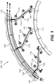
- FIG. 1 a partial view of an embodiment of a system in accordance with the disclosure is shown in Fig. 1 and is designated generally by reference character 100.
- FIGs. 2-7 Other embodiments of systems in accordance with the disclosure, or aspects thereof, are provided in Figs. 2-7 , as will be described.
- the systems and methods described herein can be used to facilitate manufacturing of internally manifolded multipoint fuel injection systems such as in gas turbine engines.
- the multipoint fuel injection system 100 comprises a plurality of injection system segments 102, one of which is shown in Fig. 1 .
- the injection system segment 102 includes a circumferentially extending outer support 104 defining a fuel manifold therein with a plurality of manifold passages 106 (labeled in Fig. 4 ) extending circumferentially therethrough.
- a first connector 108 is included at a first circumferential end of the outer support 104.
- a second connector 110 is included at a second circumferential end of the outer support 104 opposite the first circumferential end.
- the first and second connectors 108, 110 are each configured to connect each manifold passage 106 (schematically shown in Fig. 1 , but see Fig. 4 ) with a passage 106 of a respective outer support 104 of a circumferentially adjacent injection system segment 102, as shown in Figs. 2-3 .
- the injection system segment 102 includes a circumferentially extending inner support 112 and a plurality of circumferentially spaced apart feed arms 114 extending radially between the inner support 112 and the outer support 104.
- a plurality of outlet openings 116 extend in an axial direction A (labeled in Fig. 4 , but which is into and out of the view in Fig. 1 ) from each feed arm 114 for feeding respective injection nozzles 118 (labeled in Fig. 3 ).
- the feed arm 114 defines a plurality of fuel passages 120 therethrough in fluid communication with the fuel manifold passages 106 and outlet openings to supply fuel from the fuel manifold to the outlet openings.
- the system 100 includes five injection system segments 102, each as described above with reference to Fig. 1 .
- the injection system segments 102 are connected circumferentially together with each respective first connector 108 connected to a respective second connector 110 of a circumferentially adjacent one of the injection system segments 102 by a respective segment connector 122.
- One of the segment connectors 124 includes a system inlet 126 for supplying fuel to the manifolds of the injection system segments 102.
- the system 100 includes a combustor dome 128 configured for defining a combustion space downstream thereof.
- the combustor dome 128 can separate between upstream compressor components and downstream combustor and turbine components, i.e. in a gas turbine engine.
- a plurality of injection nozzles 118 extend from the outlet openings 116 (labeled in Fig. 1 ) of the feed arms 114 through the combustor dome 128 for injection of fuel from the feed arms 114, and for the injection of compressed air for mixing with the fuel, into the combustor space for combustion.
- each segment connector 122 includes a plurality of connector tubes 130 connecting between circumferentially adjacent connectors 108 and 110 of two respective segments 102.
- Each of the first and second connectors 108 and 110 includes a transition region 134 wherein each manifold passage 106 transitions from the vaulted cross-sectional flow area shown in Fig. 5 to a circular flow area 140 as shown in Fig. 6 for connection to the connector tubes 130.
- each segment connector 122 includes a heat shield 132 shielding the connector tubes 130.
- a single heat shield 136 extends from the outer support 104 to the inner support 112 and extending about the outer support 104 and the feed arms 114 to provide heat shielding to the fuel manifold passages 106 and the fuel passages 120 (labeled in Fig. 1 ).
- the feed arms 114 and a portion of the heat shield 136 adjacent to the feed arms can follow a vaulted angle ⁇ relative to the axial direction A, and define a vaulted peak 138 pointed in an axial direction A opposite that of the outlet openings 116.
- the manifold passages 106 (labeled in Fig.
- the fuel passages 120 (labeled in Fig. 1 ) in the feed arms 114 can define a plurality of similarly axially vaulted chambers to those of the manifold passages 106, peaking in the same direction.
- the vaulted angles on surfaces described here facilitate self-supporting of the heat shield 136, feed arms 114, fuel passages 120, and manifold passages 106 during additive manufacture.
- the injection system segments 102 can be additively manufactured individually in a single additive manufacturing system, or multiple additive manufacturing systems (e.g. simultaneously).
- the outer supports 104 can define an outer diameter OD (labeled in Fig. 2 ) greater than 10 inches (25.4 cm), or even greater than 15 inches (38.1 cm), but the individual segments 102 are small in enough to be additively manufactured in a build area much smaller than the outer diameter OD.
- the outer diameter OD for the fuel manifold may be 20 inches (50.8 cm), or even greater than 40 inches (101.6 cm), but using systems and method as disclosed herein, the fuel injection system 100 can be produced on additive manufacturing platforms (e.g., powder bed fusion) with build areas of 10 by 10 inches (25.4 cm) or 15 by 15 inches (38.1 cm).
- Additively manufacturing in this method includes building in an axial build direction A (identified in Fig. 4 ) beginning from downstream portions (e.g. the bottom as oriented in Fig. 4 ) of the inner and outer supports 104, 112 for each injection system segment 102.
- the method includes joining the injection system segments 102 together circumferentially end to end to form a complete multipoint fuel injection system 100.
- Joining the injection system segments 102 together can include brazing the openings of the circular flow areas 140 (labeled in Fig. 6 ) of the connectors 108, 110 of the segments 102 to connector tubes 130 connecting circumferentially between circumferentially adjacent ones of the segments 102.
- the method can include assembling a respective heat shield 132 (labeled in Fig. 7 ) about the connector tubes 130 connecting between circumferentially adjacent pairs of the segments 102.
- the inlet connector 124 can be brazed to the respective connectors 108, 110 of one pair of adjacent injection system segments 102, and can be shielded with a similar heat shield to that shown in Fig. 7 .
Landscapes
- Engineering & Computer Science (AREA)
- Chemical & Material Sciences (AREA)
- Combustion & Propulsion (AREA)
- Mechanical Engineering (AREA)
- General Engineering & Computer Science (AREA)
- Fuel-Injection Apparatus (AREA)
Description
- The present disclosure relates to combustion systems, and more particularly to fuel manifolds for gas turbine engines.
- Multipoint fuel injection systems would benefit from a simple, low cost fuel injector and manifold construction to permit a large number of injectors to be used. Traditional fuel injector and nozzle designs require complex manifolding that can impede air flow from a compressor to the combustor in a gas turbine engine. Advanced engines require thermal protection to prevent fuel from reaching a temperature where it can break down and grow internal carbon buildup. The conventional techniques have been considered satisfactory for their intended purpose. However, there is an ever present need for improved systems and methods for combustion systems. This disclosure provides a solution for this need.
- A fuel injection injection system according to the prior art is described by documents
WO2013/188723 andEP3382280 . - A multipoint fuel injection system is provided as defined by claim 1. The injection system segment can be a first injection system segment of a plurality of such injection system segments, wherein the injection system segments are connected circumferentially together with each respective first connector connected to a respective second connector of a circumferentially adjacent one of the injection system segments by a respective segment connector. Each segment connector can include a plurality of connector tubes connecting between circumferentially adjacent connectors. One of the segment connectors can include a system inlet for supplying fuel to the manifolds of the injection system segments. Each segment connector can include a heat shield shielding the connector tubes.
- The injection system segments can be additively manufactured. The outer supports can define an outer diameter greater than 10 inches (25.4 cm), or even greater than 15 inches (38.1 cm). A single heat shield can extend from the outer support to the inner support and extending about the outer support and the feed arms to provide heat shielding to the fuel manifold and the fuel passages.
- The feed arm and a portion of the heat shield adjacent to the feed arm can follow a vaulted angle. The feed arm and the portion of the heat shield adjacent to the feed arm can define at least one vaulted peak pointed in an axial direction opposite that of the outlet openings. The manifold passages can have axially oriented vaulted surfaces. The fuel passages in the feed arm can define a plurality of axially vaulted chambers.
- The system can include a combustor dome configured for defining a combustion space. The system can include a plurality of injection nozzles extending from the outlet openings of the feed arm through the combustor dome for injection of fuel from the feed arm into the combustor space.
- A method is also provided as defined by claim 11.
- Additively manufacturing the injection system segments can be performed on one or more additively manufacturing systems, each having a smaller build area than the diameter of the multipoint fuel injection system. Joining the injection system segments together can include brazing the segments to connector tubes connecting circumferentially between circumferentially adjacent ones of the segments. The method can include assembling a respective heat shield about the connector tubes connecting between circumferentially adjacent pairs of the segments. Additively manufacturing can include forming a heat shield extending from the outer support to the inner support and extending about the outer support and the feed arm.
- These and other features of the systems and methods of the subject disclosure will become more readily apparent to those skilled in the art from the following detailed description of the preferred embodiments taken in conjunction with the drawings.
- So that those skilled in the art to which the subject disclosure appertains will readily understand how to make and use the devices and methods of the subject disclosure without undue experimentation, preferred embodiments thereof will be described in detail herein below with reference to certain figures, wherein:
-
Fig. 1 is an inlet end elevation view of an embodiment of a portion of multipoint fuel injection system in accordance with the present disclosure, showing the one of the injection system segments; -
Fig. 2 is an inlet end elevation view of the system ofFig. 1 , showing five injection system segments connected together; -
Fig. 3 is an inlet end elevation view of the system ofFig. 1 , showing the combustor dome and injection nozzles; -
Fig. 4 is a perspective view of a portion of the system ofFig. 1 , showing the connection between two of the injection system segments; -
Fig. 5 is a radial cross-sectional elevation view of a portion of the system ofFig. 1 , showing the manifold passages at the location indicated inFig. 4 ; -
Fig. 6 is a radial cross-sectional elevation view of a portion of the system ofFig. 1 , showing the circular flow area at the location indicated inFig. 4 for connection of the injection system segment to the connector tubes; and -
Fig. 7 is a perspective view of a portion of the system ofFig. 1 , showing a heat shield over the connector tubes. - Reference will now be made to the drawings wherein like reference numerals identify similar structural features or aspects of the subject disclosure. For purposes of explanation and illustration, and not limitation, a partial view of an embodiment of a system in accordance with the disclosure is shown in
Fig. 1 and is designated generally byreference character 100. Other embodiments of systems in accordance with the disclosure, or aspects thereof, are provided inFigs. 2-7 , as will be described. The systems and methods described herein can be used to facilitate manufacturing of internally manifolded multipoint fuel injection systems such as in gas turbine engines. - The multipoint
fuel injection system 100 comprises a plurality ofinjection system segments 102, one of which is shown inFig. 1 . Theinjection system segment 102 includes a circumferentially extendingouter support 104 defining a fuel manifold therein with a plurality of manifold passages 106 (labeled inFig. 4 ) extending circumferentially therethrough. Afirst connector 108 is included at a first circumferential end of theouter support 104. Asecond connector 110 is included at a second circumferential end of theouter support 104 opposite the first circumferential end. The first andsecond connectors Fig. 1 , but seeFig. 4 ) with apassage 106 of a respectiveouter support 104 of a circumferentially adjacentinjection system segment 102, as shown inFigs. 2-3 . - With continued reference to
Fig. 1 , theinjection system segment 102 includes a circumferentially extendinginner support 112 and a plurality of circumferentially spaced apartfeed arms 114 extending radially between theinner support 112 and theouter support 104. A plurality ofoutlet openings 116 extend in an axial direction A (labeled inFig. 4 , but which is into and out of the view inFig. 1 ) from eachfeed arm 114 for feeding respective injection nozzles 118 (labeled inFig. 3 ). Thefeed arm 114 defines a plurality offuel passages 120 therethrough in fluid communication with thefuel manifold passages 106 and outlet openings to supply fuel from the fuel manifold to the outlet openings. The flow paths through two of themanifold passages 106 andrespective fuel passages 120 are schematically indicated by the flow arrows inFig. 1 , but those skilled in the art will readily appreciate that there are a total of six such flow paths feeding the sixrespective outlets 116 of eachfeed arm 114. - With reference now to
Fig. 2 , thesystem 100 includes fiveinjection system segments 102, each as described above with reference toFig. 1 . Those skilled in the art will readily appreciate that any suitable number of segments besides five can be used for a given application. Theinjection system segments 102 are connected circumferentially together with each respectivefirst connector 108 connected to a respectivesecond connector 110 of a circumferentially adjacent one of theinjection system segments 102 by arespective segment connector 122. One of the segment connectors 124 includes a system inlet 126 for supplying fuel to the manifolds of theinjection system segments 102. - With reference now to
Fig. 3 , thesystem 100 includes acombustor dome 128 configured for defining a combustion space downstream thereof. Thecombustor dome 128 can separate between upstream compressor components and downstream combustor and turbine components, i.e. in a gas turbine engine. A plurality ofinjection nozzles 118 extend from the outlet openings 116 (labeled inFig. 1 ) of thefeed arms 114 through thecombustor dome 128 for injection of fuel from thefeed arms 114, and for the injection of compressed air for mixing with the fuel, into the combustor space for combustion. - With reference now to
Fig. 4 , eachsegment connector 122 includes a plurality ofconnector tubes 130 connecting between circumferentiallyadjacent connectors respective segments 102. Each of the first andsecond connectors transition region 134 wherein eachmanifold passage 106 transitions from the vaulted cross-sectional flow area shown inFig. 5 to acircular flow area 140 as shown inFig. 6 for connection to theconnector tubes 130. - With reference now to
Fig. 7 , eachsegment connector 122 includes aheat shield 132 shielding theconnector tubes 130. Asingle heat shield 136 extends from theouter support 104 to theinner support 112 and extending about theouter support 104 and thefeed arms 114 to provide heat shielding to thefuel manifold passages 106 and the fuel passages 120 (labeled inFig. 1 ). As shown inFig. 4 , thefeed arms 114 and a portion of theheat shield 136 adjacent to the feed arms can follow a vaulted angle θ relative to the axial direction A, and define a vaultedpeak 138 pointed in an axial direction A opposite that of theoutlet openings 116. The manifold passages 106 (labeled inFig. 5 ) have a vaulted cross-sectional flow area defined by chevron-shaped surfaces oriented to peak in the axial direction A. The fuel passages 120 (labeled inFig. 1 ) in thefeed arms 114 can define a plurality of similarly axially vaulted chambers to those of themanifold passages 106, peaking in the same direction. The vaulted angles on surfaces described here facilitate self-supporting of theheat shield 136, feedarms 114,fuel passages 120, andmanifold passages 106 during additive manufacture. - The
injection system segments 102 can be additively manufactured individually in a single additive manufacturing system, or multiple additive manufacturing systems (e.g. simultaneously). The outer supports 104 can define an outer diameter OD (labeled inFig. 2 ) greater than 10 inches (25.4 cm), or even greater than 15 inches (38.1 cm), but theindividual segments 102 are small in enough to be additively manufactured in a build area much smaller than the outer diameter OD. For example, in a typical gas turbine engine the outer diameter OD for the fuel manifold may be 20 inches (50.8 cm), or even greater than 40 inches (101.6 cm), but using systems and method as disclosed herein, thefuel injection system 100 can be produced on additive manufacturing platforms (e.g., powder bed fusion) with build areas of 10 by 10 inches (25.4 cm) or 15 by 15 inches (38.1 cm). Additively manufacturing in this method includes building in an axial build direction A (identified inFig. 4 ) beginning from downstream portions (e.g. the bottom as oriented inFig. 4 ) of the inner andouter supports injection system segment 102. - The method includes joining the
injection system segments 102 together circumferentially end to end to form a complete multipointfuel injection system 100. Joining theinjection system segments 102 together can include brazing the openings of the circular flow areas 140 (labeled inFig. 6 ) of theconnectors segments 102 toconnector tubes 130 connecting circumferentially between circumferentially adjacent ones of thesegments 102. The method can include assembling a respective heat shield 132 (labeled inFig. 7 ) about theconnector tubes 130 connecting between circumferentially adjacent pairs of thesegments 102. The inlet connector 124 can be brazed to therespective connectors injection system segments 102, and can be shielded with a similar heat shield to that shown inFig. 7 . - The methods and systems of the present disclosure, as described above and shown in the drawings, provide for multipoint fuel injection systems with superior properties including improved manufacturability. While the apparatus and methods of the subject disclosure have been shown and described with reference to preferred embodiments, those skilled in the art will readily appreciate that changes and/or modifications may be made thereto without departing from the scope of the invention as defined by the claims.
Claims (14)
- A multipoint fuel injection system comprising:
an injection system segment (102) including:a circumferentially extending outer support (104) defining a fuel manifold with a plurality of manifold passages (106) extending circumferentially therethrough, and with a first connector (108) at a first circumferential end of the outer support and with a second connector (110) at a second circumferential end of the outer support opposite the first circumferential end, wherein the first and second connectors are each configured to connect each manifold passage with a manifold passages of a respective outer support of a circumferentially adjacent injection system segment;a circumferentially extending inner support (112);a plurality of circumferentially spaced apart feed arms (114) extending radially between the inner support and the outer support; anda plurality of outlet openings (116) extending in an axial direction from each feed arm for feeding respective injection nozzles, wherein the feed arm defines a plurality of fuel passages (120) therethrough in fluid communication with the fuel manifold and outlet openings to supply fuel from the fuel manifold to the outlet openings; characterized in thatthe manifold passages (106) have a vaulted cross-sectional flow area, and in that each of the first and second connectors includes a transition region wherein each manifold passage transitions from the vaulted cross-sectional flow area to a circular flow area for connection to connector tubes. - The system as recited in claim 1, wherein the injection system segment is a first injection system segment of a plurality of such injection system segments, wherein the injection system segments are connected circumferentially together with each respective first connector connected to a respective second connector of a circumferentially adjacent one of the injection system segments by a respective segment connector.
- The system as recited in claim 2, wherein each segment connector includes a plurality of connector tubes (130) connecting between circumferentially adjacent connectors.
- The system as recited in claim 3, wherein one of the segment connectors includes a system inlet for supplying fuel to the manifolds of the injection system segments.
- The system as recited in claim 3, wherein each segment connector includes a heat shield (132) shielding the connector tubes.
- The system as recited in claim 2, wherein the injection system segments are additively manufactured, and wherein the outer supports define an outer diameter greater than 25.4 cm (10 inches) or wherein the injection system segments are additively manufactured, and wherein the outer supports define an outer diameter greater than 38.1 cm (15 inches).
- The system as recited in any preceding claim, wherein a single heat shield extends from the outer support to the inner support and extending about the outer support and the feed arms to provide heat shielding to the fuel manifold and the fuel passages, and optionally wherein the feed arm and a portion of the heat shield adjacent to the feed arm follow a vaulted angle, and optionally wherein the feed arm and the portion of the heat shield adjacent to the feed arm define at least one vaulted peak pointed in an axial direction opposite that of the outlet openings.
- The system as recited in any preceding claim, wherein the manifold passages have axially oriented vaulted surfaces.
- The system as recited in any preceding claim, further comprising a combustor dome (128) configured for defining a combustion space, and a plurality of injection nozzles extending from the outlet openings of the feed arm through the combustor dome for injection of fuel from the feed arm into the combustor space.
- The system as recited in any preceding claim, wherein the fuel passages in the feed arm define a plurality of axially vaulted chambers.
- A method comprising:additively manufacturing a plurality of injection system segments, each including a circumferentially extending outer support comprising a plurality of manifold passages (106),together with a circumferentially extending inner support, a feed arm extending radially between the inner support and the outer support, wherein the additively manufacturing includes building in an axial build direction beginning from downstream portions of the inner and outer supports for each injection system segment, forming a first connector (108) at a first circumferential end of the outer support and a second connector (110) at a second circumferential end of the outer support opposite the first circumferential end, wherein the first and second connectors are each configured to connect each manifold passage with a manifold passages of a respective outer support of a circumferentially adjacent injection system segment; and forming a plurality of outlet openings (116) extending in an axial direction from each feed arm for feeding respective injection nozzles, wherein the feed arm defines a plurality of fuel passages (120) therethrough in fluid communication with the fuel manifold and outlet openings to supply fuel from the fuel manifold to the outlet openings; and characterized in that
the manifold passages (106) have a vaulted cross-sectional flow area, and wherein each of the first and second connectors includes a transition region wherein each manifold passage transitions from the vaulted cross-sectional flow area to a circular flow area for connection to connector tubes; andjoining the injection system segments together circumferentially end to end to form a multipoint fuel injection system as recited in any previous claim. - The method as recited in claim 11, wherein the multipoint fuel injection system has an outer diameter, wherein additively manufacturing the injection system segments is performed on one or more additively manufacturing systems, each having a smaller build area than the diameter of the multipoint fuel injection system.
- The method as recited in claim 12, wherein joining the injection system segments together includes brazing the segments to connector tubes connecting circumferentially between circumferentially adjacent ones of the segments and optionally further comprising assembling a respective heat shield about the connector tubes connecting between circumferentially adjacent pairs of the segments.
- The method as recited in any of claims 11 to 13, wherein additively manufacturing includes forming a heat shield extending from the outer support to the inner support and extending about the outer support and the feed arm.
Applications Claiming Priority (1)
| Application Number | Priority Date | Filing Date | Title |
|---|---|---|---|
| US16/518,282 US11187155B2 (en) | 2019-07-22 | 2019-07-22 | Sectional fuel manifolds |
Publications (2)
| Publication Number | Publication Date |
|---|---|
| EP3770502A1 EP3770502A1 (en) | 2021-01-27 |
| EP3770502B1 true EP3770502B1 (en) | 2023-01-25 |
Family
ID=68771466
Family Applications (1)
| Application Number | Title | Priority Date | Filing Date |
|---|---|---|---|
| EP19213478.1A Active EP3770502B1 (en) | 2019-07-22 | 2019-12-04 | Multipoint fuel injection system and related manufacturing method |
Country Status (2)
| Country | Link |
|---|---|
| US (3) | US11187155B2 (en) |
| EP (1) | EP3770502B1 (en) |
Families Citing this family (4)
| Publication number | Priority date | Publication date | Assignee | Title |
|---|---|---|---|---|
| US11369985B2 (en) | 2019-10-04 | 2022-06-28 | Delavan Inc | Fluid conduits with heat shielding |
| US11668242B2 (en) * | 2020-09-29 | 2023-06-06 | General Electric Company | Fuel injection assembly for a turbomachine |
| US12158108B2 (en) | 2023-02-14 | 2024-12-03 | Collins Engine Nozzles, Inc. | Slanted loading for line replaceable multipoint fuel injector arrays |
| DE102023132050A1 (en) * | 2023-11-17 | 2025-05-22 | Man Energy Solutions Se | Gas turbine burner |
Family Cites Families (32)
| Publication number | Priority date | Publication date | Assignee | Title |
|---|---|---|---|---|
| US2970438A (en) | 1958-03-04 | 1961-02-07 | Curtiss Wright Corp | Circular fuel spray bars |
| US6540162B1 (en) | 2000-06-28 | 2003-04-01 | General Electric Company | Methods and apparatus for decreasing combustor emissions with spray bar assembly |
| US8272219B1 (en) * | 2000-11-03 | 2012-09-25 | General Electric Company | Gas turbine engine combustor having trapped dual vortex cavity |
| US7607226B2 (en) | 2006-03-03 | 2009-10-27 | Pratt & Whitney Canada Corp. | Internal fuel manifold with turned channel having a variable cross-sectional area |
| US8037690B2 (en) | 2008-12-17 | 2011-10-18 | Pratt & Whitney Canada Corp. | Fuel manifold for gas turbine engine |
| US8418468B2 (en) | 2010-04-06 | 2013-04-16 | General Electric Company | Segmented annular ring-manifold quaternary fuel distributor |
| US20110247590A1 (en) | 2010-04-07 | 2011-10-13 | Delavan Inc | Injectors utilizing lattice support structure |
| US9644844B2 (en) | 2011-11-03 | 2017-05-09 | Delavan Inc. | Multipoint fuel injection arrangements |
| EP2877711A1 (en) * | 2012-06-15 | 2015-06-03 | General Electric Company | Fluid conduit |
| US9920693B2 (en) | 2013-03-14 | 2018-03-20 | United Technologies Corporation | Hollow-wall heat shield for fuel injector component |
| US8984896B2 (en) * | 2013-08-23 | 2015-03-24 | Pratt & Whitney Canada Corp. | Interlocking combustor heat shield panels |
| US9528705B2 (en) | 2014-04-08 | 2016-12-27 | General Electric Company | Trapped vortex fuel injector and method for manufacture |
| EP3023696B1 (en) * | 2014-11-20 | 2019-08-28 | Ansaldo Energia Switzerland AG | Lobe lance for a gas turbine combustor |
| US10100675B2 (en) * | 2014-12-09 | 2018-10-16 | United Technologies Corporation | Outer diffuser case for a gas turbine engine |
| GB2536965B (en) | 2015-04-02 | 2020-02-12 | Hamworthy Combustion Engineering Ltd | Atomizer with an Outlet having a Non-Circular Internal and/or External Cross-Section |
| US10041679B2 (en) * | 2015-06-24 | 2018-08-07 | Delavan Inc | Combustion systems |
| US10364751B2 (en) * | 2015-08-03 | 2019-07-30 | Delavan Inc | Fuel staging |
| US10508600B2 (en) * | 2016-05-27 | 2019-12-17 | Pratt & Whitney Canada Corp. | Fire shield integrated to fuel nozzle retaining bracket |
| US10502425B2 (en) | 2016-06-03 | 2019-12-10 | General Electric Company | Contoured shroud swirling pre-mix fuel injector assembly |
| US20170363294A1 (en) | 2016-06-21 | 2017-12-21 | General Electric Company | Pilot premix nozzle and fuel nozzle assembly |
| US10876477B2 (en) * | 2016-09-16 | 2020-12-29 | Delavan Inc | Nozzles with internal manifolding |
| US10465909B2 (en) | 2016-11-04 | 2019-11-05 | General Electric Company | Mini mixing fuel nozzle assembly with mixing sleeve |
| US10526972B2 (en) | 2016-12-07 | 2020-01-07 | Rolls-Royce Corporation | Segmented fuel delivery system |
| US10859269B2 (en) | 2017-03-31 | 2020-12-08 | Delavan Inc. | Fuel injectors for multipoint arrays |
| US11022240B2 (en) * | 2017-06-12 | 2021-06-01 | General Electric Company | Cooling and insulating manifold seal assembly for a propulsion system |
| US20190107285A1 (en) * | 2017-10-06 | 2019-04-11 | Pratt & Whitney Canada Corp. | Segmented fuel distributor |
| US20190234310A1 (en) * | 2018-01-29 | 2019-08-01 | Pratt & Whitney Canada Corp. | Segmented internal fuel manifold |
| US10605171B2 (en) * | 2018-04-10 | 2020-03-31 | Delavan Inc. | Fuel nozzle manifold systems for turbomachines |
| US11060459B2 (en) | 2018-07-10 | 2021-07-13 | Delavan Inc. | Internal manifold for multipoint injection |
| US11035296B2 (en) * | 2018-07-10 | 2021-06-15 | Delavan Inc. | Internal manifold for multipoint injection |
| US11187154B2 (en) * | 2018-09-25 | 2021-11-30 | Woodward, Inc. | Composite spray bars |
| US11408609B2 (en) * | 2018-10-26 | 2022-08-09 | Collins Engine Nozzles, Inc. | Combustor dome tiles |
-
2019
- 2019-07-22 US US16/518,282 patent/US11187155B2/en active Active
- 2019-12-04 EP EP19213478.1A patent/EP3770502B1/en active Active
-
2021
- 2021-11-12 US US17/525,386 patent/US11713717B2/en active Active
-
2023
- 2023-07-18 US US18/223,173 patent/US12196135B2/en active Active
Also Published As
| Publication number | Publication date |
|---|---|
| US20230358172A1 (en) | 2023-11-09 |
| EP3770502A1 (en) | 2021-01-27 |
| US11187155B2 (en) | 2021-11-30 |
| US20220065167A1 (en) | 2022-03-03 |
| US11713717B2 (en) | 2023-08-01 |
| US20210025329A1 (en) | 2021-01-28 |
| US12196135B2 (en) | 2025-01-14 |
Similar Documents
| Publication | Publication Date | Title |
|---|---|---|
| US11713717B2 (en) | Sectional fuel manifolds | |
| US12416410B2 (en) | Fuel injectors for multipoint arrays | |
| US11692487B2 (en) | Heat shielding for internal fuel manifolds | |
| EP3431878B1 (en) | Fuel nozzles | |
| EP3553383B1 (en) | Fuel injectors for turbomachines | |
| US9267436B2 (en) | Fuel distribution manifold for a combustor of a gas turbine | |
| EP2902605B1 (en) | A fuel manifold and fuel injector arrangement for a gas turbine engine | |
| US11674687B2 (en) | Fuel manifolds | |
| US10605171B2 (en) | Fuel nozzle manifold systems for turbomachines | |
| US11994297B2 (en) | Fluid nozzles with heat shielding | |
| EP3499126B1 (en) | Fuel injectors assembly | |
| CN103339443A (en) | Injection device for a turbo machine combustion chamber |
Legal Events
| Date | Code | Title | Description |
|---|---|---|---|
| PUAI | Public reference made under article 153(3) epc to a published international application that has entered the european phase |
Free format text: ORIGINAL CODE: 0009012 |
|
| STAA | Information on the status of an ep patent application or granted ep patent |
Free format text: STATUS: THE APPLICATION HAS BEEN PUBLISHED |
|
| AK | Designated contracting states |
Kind code of ref document: A1 Designated state(s): AL AT BE BG CH CY CZ DE DK EE ES FI FR GB GR HR HU IE IS IT LI LT LU LV MC MK MT NL NO PL PT RO RS SE SI SK SM TR |
|
| STAA | Information on the status of an ep patent application or granted ep patent |
Free format text: STATUS: REQUEST FOR EXAMINATION WAS MADE |
|
| 17P | Request for examination filed |
Effective date: 20210727 |
|
| RBV | Designated contracting states (corrected) |
Designated state(s): AL AT BE BG CH CY CZ DE DK EE ES FI FR GB GR HR HU IE IS IT LI LT LU LV MC MK MT NL NO PL PT RO RS SE SI SK SM TR |
|
| RAP3 | Party data changed (applicant data changed or rights of an application transferred) |
Owner name: COLLINS ENGINE NOZZLES, INC. |
|
| GRAP | Despatch of communication of intention to grant a patent |
Free format text: ORIGINAL CODE: EPIDOSNIGR1 |
|
| STAA | Information on the status of an ep patent application or granted ep patent |
Free format text: STATUS: GRANT OF PATENT IS INTENDED |
|
| INTG | Intention to grant announced |
Effective date: 20220706 |
|
| GRAS | Grant fee paid |
Free format text: ORIGINAL CODE: EPIDOSNIGR3 |
|
| GRAA | (expected) grant |
Free format text: ORIGINAL CODE: 0009210 |
|
| STAA | Information on the status of an ep patent application or granted ep patent |
Free format text: STATUS: THE PATENT HAS BEEN GRANTED |
|
| AK | Designated contracting states |
Kind code of ref document: B1 Designated state(s): AL AT BE BG CH CY CZ DE DK EE ES FI FR GB GR HR HU IE IS IT LI LT LU LV MC MK MT NL NO PL PT RO RS SE SI SK SM TR |
|
| REG | Reference to a national code |
Ref country code: GB Ref legal event code: FG4D |
|
| REG | Reference to a national code |
Ref country code: CH Ref legal event code: EP |
|
| REG | Reference to a national code |
Ref country code: AT Ref legal event code: REF Ref document number: 1546143 Country of ref document: AT Kind code of ref document: T Effective date: 20230215 Ref country code: IE Ref legal event code: FG4D |
|
| REG | Reference to a national code |
Ref country code: DE Ref legal event code: R096 Ref document number: 602019024741 Country of ref document: DE |
|
| REG | Reference to a national code |
Ref country code: LT Ref legal event code: MG9D |
|
| REG | Reference to a national code |
Ref country code: NL Ref legal event code: MP Effective date: 20230125 |
|
| REG | Reference to a national code |
Ref country code: AT Ref legal event code: MK05 Ref document number: 1546143 Country of ref document: AT Kind code of ref document: T Effective date: 20230125 |
|
| PG25 | Lapsed in a contracting state [announced via postgrant information from national office to epo] |
Ref country code: NL Free format text: LAPSE BECAUSE OF FAILURE TO SUBMIT A TRANSLATION OF THE DESCRIPTION OR TO PAY THE FEE WITHIN THE PRESCRIBED TIME-LIMIT Effective date: 20230125 |
|
| P01 | Opt-out of the competence of the unified patent court (upc) registered |
Effective date: 20230530 |
|
| PG25 | Lapsed in a contracting state [announced via postgrant information from national office to epo] |
Ref country code: RS Free format text: LAPSE BECAUSE OF FAILURE TO SUBMIT A TRANSLATION OF THE DESCRIPTION OR TO PAY THE FEE WITHIN THE PRESCRIBED TIME-LIMIT Effective date: 20230125 Ref country code: PT Free format text: LAPSE BECAUSE OF FAILURE TO SUBMIT A TRANSLATION OF THE DESCRIPTION OR TO PAY THE FEE WITHIN THE PRESCRIBED TIME-LIMIT Effective date: 20230525 Ref country code: NO Free format text: LAPSE BECAUSE OF FAILURE TO SUBMIT A TRANSLATION OF THE DESCRIPTION OR TO PAY THE FEE WITHIN THE PRESCRIBED TIME-LIMIT Effective date: 20230425 Ref country code: LV Free format text: LAPSE BECAUSE OF FAILURE TO SUBMIT A TRANSLATION OF THE DESCRIPTION OR TO PAY THE FEE WITHIN THE PRESCRIBED TIME-LIMIT Effective date: 20230125 Ref country code: LT Free format text: LAPSE BECAUSE OF FAILURE TO SUBMIT A TRANSLATION OF THE DESCRIPTION OR TO PAY THE FEE WITHIN THE PRESCRIBED TIME-LIMIT Effective date: 20230125 Ref country code: HR Free format text: LAPSE BECAUSE OF FAILURE TO SUBMIT A TRANSLATION OF THE DESCRIPTION OR TO PAY THE FEE WITHIN THE PRESCRIBED TIME-LIMIT Effective date: 20230125 Ref country code: ES Free format text: LAPSE BECAUSE OF FAILURE TO SUBMIT A TRANSLATION OF THE DESCRIPTION OR TO PAY THE FEE WITHIN THE PRESCRIBED TIME-LIMIT Effective date: 20230125 Ref country code: AT Free format text: LAPSE BECAUSE OF FAILURE TO SUBMIT A TRANSLATION OF THE DESCRIPTION OR TO PAY THE FEE WITHIN THE PRESCRIBED TIME-LIMIT Effective date: 20230125 |
|
| PG25 | Lapsed in a contracting state [announced via postgrant information from national office to epo] |
Ref country code: SE Free format text: LAPSE BECAUSE OF FAILURE TO SUBMIT A TRANSLATION OF THE DESCRIPTION OR TO PAY THE FEE WITHIN THE PRESCRIBED TIME-LIMIT Effective date: 20230125 Ref country code: PL Free format text: LAPSE BECAUSE OF FAILURE TO SUBMIT A TRANSLATION OF THE DESCRIPTION OR TO PAY THE FEE WITHIN THE PRESCRIBED TIME-LIMIT Effective date: 20230125 Ref country code: IS Free format text: LAPSE BECAUSE OF FAILURE TO SUBMIT A TRANSLATION OF THE DESCRIPTION OR TO PAY THE FEE WITHIN THE PRESCRIBED TIME-LIMIT Effective date: 20230525 Ref country code: GR Free format text: LAPSE BECAUSE OF FAILURE TO SUBMIT A TRANSLATION OF THE DESCRIPTION OR TO PAY THE FEE WITHIN THE PRESCRIBED TIME-LIMIT Effective date: 20230426 Ref country code: FI Free format text: LAPSE BECAUSE OF FAILURE TO SUBMIT A TRANSLATION OF THE DESCRIPTION OR TO PAY THE FEE WITHIN THE PRESCRIBED TIME-LIMIT Effective date: 20230125 |
|
| REG | Reference to a national code |
Ref country code: DE Ref legal event code: R097 Ref document number: 602019024741 Country of ref document: DE |
|
| PG25 | Lapsed in a contracting state [announced via postgrant information from national office to epo] |
Ref country code: SM Free format text: LAPSE BECAUSE OF FAILURE TO SUBMIT A TRANSLATION OF THE DESCRIPTION OR TO PAY THE FEE WITHIN THE PRESCRIBED TIME-LIMIT Effective date: 20230125 Ref country code: RO Free format text: LAPSE BECAUSE OF FAILURE TO SUBMIT A TRANSLATION OF THE DESCRIPTION OR TO PAY THE FEE WITHIN THE PRESCRIBED TIME-LIMIT Effective date: 20230125 Ref country code: EE Free format text: LAPSE BECAUSE OF FAILURE TO SUBMIT A TRANSLATION OF THE DESCRIPTION OR TO PAY THE FEE WITHIN THE PRESCRIBED TIME-LIMIT Effective date: 20230125 Ref country code: DK Free format text: LAPSE BECAUSE OF FAILURE TO SUBMIT A TRANSLATION OF THE DESCRIPTION OR TO PAY THE FEE WITHIN THE PRESCRIBED TIME-LIMIT Effective date: 20230125 Ref country code: CZ Free format text: LAPSE BECAUSE OF FAILURE TO SUBMIT A TRANSLATION OF THE DESCRIPTION OR TO PAY THE FEE WITHIN THE PRESCRIBED TIME-LIMIT Effective date: 20230125 |
|
| PG25 | Lapsed in a contracting state [announced via postgrant information from national office to epo] |
Ref country code: SK Free format text: LAPSE BECAUSE OF FAILURE TO SUBMIT A TRANSLATION OF THE DESCRIPTION OR TO PAY THE FEE WITHIN THE PRESCRIBED TIME-LIMIT Effective date: 20230125 |
|
| PLBE | No opposition filed within time limit |
Free format text: ORIGINAL CODE: 0009261 |
|
| STAA | Information on the status of an ep patent application or granted ep patent |
Free format text: STATUS: NO OPPOSITION FILED WITHIN TIME LIMIT |
|
| 26N | No opposition filed |
Effective date: 20231026 |
|
| PG25 | Lapsed in a contracting state [announced via postgrant information from national office to epo] |
Ref country code: SI Free format text: LAPSE BECAUSE OF FAILURE TO SUBMIT A TRANSLATION OF THE DESCRIPTION OR TO PAY THE FEE WITHIN THE PRESCRIBED TIME-LIMIT Effective date: 20230125 |
|
| PG25 | Lapsed in a contracting state [announced via postgrant information from national office to epo] |
Ref country code: IT Free format text: LAPSE BECAUSE OF FAILURE TO SUBMIT A TRANSLATION OF THE DESCRIPTION OR TO PAY THE FEE WITHIN THE PRESCRIBED TIME-LIMIT Effective date: 20230125 |
|
| REG | Reference to a national code |
Ref country code: CH Ref legal event code: PL |
|
| PG25 | Lapsed in a contracting state [announced via postgrant information from national office to epo] |
Ref country code: LU Free format text: LAPSE BECAUSE OF NON-PAYMENT OF DUE FEES Effective date: 20231204 |
|
| PG25 | Lapsed in a contracting state [announced via postgrant information from national office to epo] |
Ref country code: MC Free format text: LAPSE BECAUSE OF FAILURE TO SUBMIT A TRANSLATION OF THE DESCRIPTION OR TO PAY THE FEE WITHIN THE PRESCRIBED TIME-LIMIT Effective date: 20230125 |
|
| REG | Reference to a national code |
Ref country code: BE Ref legal event code: MM Effective date: 20231231 |
|
| PG25 | Lapsed in a contracting state [announced via postgrant information from national office to epo] |
Ref country code: MC Free format text: LAPSE BECAUSE OF FAILURE TO SUBMIT A TRANSLATION OF THE DESCRIPTION OR TO PAY THE FEE WITHIN THE PRESCRIBED TIME-LIMIT Effective date: 20230125 Ref country code: LU Free format text: LAPSE BECAUSE OF NON-PAYMENT OF DUE FEES Effective date: 20231204 |
|
| REG | Reference to a national code |
Ref country code: IE Ref legal event code: MM4A |
|
| PG25 | Lapsed in a contracting state [announced via postgrant information from national office to epo] |
Ref country code: IE Free format text: LAPSE BECAUSE OF NON-PAYMENT OF DUE FEES Effective date: 20231204 |
|
| PG25 | Lapsed in a contracting state [announced via postgrant information from national office to epo] |
Ref country code: BE Free format text: LAPSE BECAUSE OF NON-PAYMENT OF DUE FEES Effective date: 20231231 |
|
| PG25 | Lapsed in a contracting state [announced via postgrant information from national office to epo] |
Ref country code: CH Free format text: LAPSE BECAUSE OF NON-PAYMENT OF DUE FEES Effective date: 20231231 |
|
| PG25 | Lapsed in a contracting state [announced via postgrant information from national office to epo] |
Ref country code: IE Free format text: LAPSE BECAUSE OF NON-PAYMENT OF DUE FEES Effective date: 20231204 Ref country code: CH Free format text: LAPSE BECAUSE OF NON-PAYMENT OF DUE FEES Effective date: 20231231 Ref country code: BE Free format text: LAPSE BECAUSE OF NON-PAYMENT OF DUE FEES Effective date: 20231231 |
|
| PG25 | Lapsed in a contracting state [announced via postgrant information from national office to epo] |
Ref country code: BG Free format text: LAPSE BECAUSE OF FAILURE TO SUBMIT A TRANSLATION OF THE DESCRIPTION OR TO PAY THE FEE WITHIN THE PRESCRIBED TIME-LIMIT Effective date: 20230125 |
|
| PG25 | Lapsed in a contracting state [announced via postgrant information from national office to epo] |
Ref country code: BG Free format text: LAPSE BECAUSE OF FAILURE TO SUBMIT A TRANSLATION OF THE DESCRIPTION OR TO PAY THE FEE WITHIN THE PRESCRIBED TIME-LIMIT Effective date: 20230125 |
|
| PG25 | Lapsed in a contracting state [announced via postgrant information from national office to epo] |
Ref country code: CY Free format text: LAPSE BECAUSE OF FAILURE TO SUBMIT A TRANSLATION OF THE DESCRIPTION OR TO PAY THE FEE WITHIN THE PRESCRIBED TIME-LIMIT; INVALID AB INITIO Effective date: 20191204 |
|
| PG25 | Lapsed in a contracting state [announced via postgrant information from national office to epo] |
Ref country code: HU Free format text: LAPSE BECAUSE OF FAILURE TO SUBMIT A TRANSLATION OF THE DESCRIPTION OR TO PAY THE FEE WITHIN THE PRESCRIBED TIME-LIMIT; INVALID AB INITIO Effective date: 20191204 |
|
| PG25 | Lapsed in a contracting state [announced via postgrant information from national office to epo] |
Ref country code: TR Free format text: LAPSE BECAUSE OF FAILURE TO SUBMIT A TRANSLATION OF THE DESCRIPTION OR TO PAY THE FEE WITHIN THE PRESCRIBED TIME-LIMIT Effective date: 20230125 |
|
| PGFP | Annual fee paid to national office [announced via postgrant information from national office to epo] |
Ref country code: DE Payment date: 20251126 Year of fee payment: 7 |
|
| PGFP | Annual fee paid to national office [announced via postgrant information from national office to epo] |
Ref country code: GB Payment date: 20251119 Year of fee payment: 7 |
|
| PGFP | Annual fee paid to national office [announced via postgrant information from national office to epo] |
Ref country code: FR Payment date: 20251120 Year of fee payment: 7 |