EP3770440A1 - Propeller fan - Google Patents
Propeller fan Download PDFInfo
- Publication number
- EP3770440A1 EP3770440A1 EP19771495.9A EP19771495A EP3770440A1 EP 3770440 A1 EP3770440 A1 EP 3770440A1 EP 19771495 A EP19771495 A EP 19771495A EP 3770440 A1 EP3770440 A1 EP 3770440A1
- Authority
- EP
- European Patent Office
- Prior art keywords
- blade
- peripheral portion
- propeller fan
- inner peripheral
- hub
- Prior art date
- Legal status (The legal status is an assumption and is not a legal conclusion. Google has not performed a legal analysis and makes no representation as to the accuracy of the status listed.)
- Granted
Links
Images





Classifications
-
- F—MECHANICAL ENGINEERING; LIGHTING; HEATING; WEAPONS; BLASTING
- F04—POSITIVE - DISPLACEMENT MACHINES FOR LIQUIDS; PUMPS FOR LIQUIDS OR ELASTIC FLUIDS
- F04D—NON-POSITIVE-DISPLACEMENT PUMPS
- F04D29/00—Details, component parts, or accessories
- F04D29/26—Rotors specially for elastic fluids
- F04D29/32—Rotors specially for elastic fluids for axial flow pumps
-
- F—MECHANICAL ENGINEERING; LIGHTING; HEATING; WEAPONS; BLASTING
- F04—POSITIVE - DISPLACEMENT MACHINES FOR LIQUIDS; PUMPS FOR LIQUIDS OR ELASTIC FLUIDS
- F04D—NON-POSITIVE-DISPLACEMENT PUMPS
- F04D25/00—Pumping installations or systems
- F04D25/02—Units comprising pumps and their driving means
- F04D25/08—Units comprising pumps and their driving means the working fluid being air, e.g. for ventilation
-
- F—MECHANICAL ENGINEERING; LIGHTING; HEATING; WEAPONS; BLASTING
- F04—POSITIVE - DISPLACEMENT MACHINES FOR LIQUIDS; PUMPS FOR LIQUIDS OR ELASTIC FLUIDS
- F04D—NON-POSITIVE-DISPLACEMENT PUMPS
- F04D29/00—Details, component parts, or accessories
- F04D29/26—Rotors specially for elastic fluids
- F04D29/32—Rotors specially for elastic fluids for axial flow pumps
- F04D29/321—Rotors specially for elastic fluids for axial flow pumps for axial flow compressors
- F04D29/322—Blade mountings
-
- F—MECHANICAL ENGINEERING; LIGHTING; HEATING; WEAPONS; BLASTING
- F04—POSITIVE - DISPLACEMENT MACHINES FOR LIQUIDS; PUMPS FOR LIQUIDS OR ELASTIC FLUIDS
- F04D—NON-POSITIVE-DISPLACEMENT PUMPS
- F04D29/00—Details, component parts, or accessories
- F04D29/26—Rotors specially for elastic fluids
- F04D29/32—Rotors specially for elastic fluids for axial flow pumps
- F04D29/325—Rotors specially for elastic fluids for axial flow pumps for axial flow fans
- F04D29/329—Details of the hub
-
- F—MECHANICAL ENGINEERING; LIGHTING; HEATING; WEAPONS; BLASTING
- F04—POSITIVE - DISPLACEMENT MACHINES FOR LIQUIDS; PUMPS FOR LIQUIDS OR ELASTIC FLUIDS
- F04D—NON-POSITIVE-DISPLACEMENT PUMPS
- F04D29/00—Details, component parts, or accessories
- F04D29/26—Rotors specially for elastic fluids
- F04D29/32—Rotors specially for elastic fluids for axial flow pumps
- F04D29/34—Blade mountings
-
- F—MECHANICAL ENGINEERING; LIGHTING; HEATING; WEAPONS; BLASTING
- F04—POSITIVE - DISPLACEMENT MACHINES FOR LIQUIDS; PUMPS FOR LIQUIDS OR ELASTIC FLUIDS
- F04D—NON-POSITIVE-DISPLACEMENT PUMPS
- F04D29/00—Details, component parts, or accessories
- F04D29/26—Rotors specially for elastic fluids
- F04D29/32—Rotors specially for elastic fluids for axial flow pumps
- F04D29/38—Blades
- F04D29/384—Blades characterised by form
-
- F—MECHANICAL ENGINEERING; LIGHTING; HEATING; WEAPONS; BLASTING
- F04—POSITIVE - DISPLACEMENT MACHINES FOR LIQUIDS; PUMPS FOR LIQUIDS OR ELASTIC FLUIDS
- F04D—NON-POSITIVE-DISPLACEMENT PUMPS
- F04D29/00—Details, component parts, or accessories
- F04D29/26—Rotors specially for elastic fluids
- F04D29/32—Rotors specially for elastic fluids for axial flow pumps
- F04D29/38—Blades
- F04D29/388—Blades characterised by construction
-
- F—MECHANICAL ENGINEERING; LIGHTING; HEATING; WEAPONS; BLASTING
- F04—POSITIVE - DISPLACEMENT MACHINES FOR LIQUIDS; PUMPS FOR LIQUIDS OR ELASTIC FLUIDS
- F04D—NON-POSITIVE-DISPLACEMENT PUMPS
- F04D29/00—Details, component parts, or accessories
- F04D29/66—Combating cavitation, whirls, noise, vibration or the like; Balancing
- F04D29/68—Combating cavitation, whirls, noise, vibration or the like; Balancing by influencing boundary layers
- F04D29/681—Combating cavitation, whirls, noise, vibration or the like; Balancing by influencing boundary layers especially adapted for elastic fluid pumps
- F04D29/682—Combating cavitation, whirls, noise, vibration or the like; Balancing by influencing boundary layers especially adapted for elastic fluid pumps by fluid extraction
-
- F—MECHANICAL ENGINEERING; LIGHTING; HEATING; WEAPONS; BLASTING
- F04—POSITIVE - DISPLACEMENT MACHINES FOR LIQUIDS; PUMPS FOR LIQUIDS OR ELASTIC FLUIDS
- F04D—NON-POSITIVE-DISPLACEMENT PUMPS
- F04D29/00—Details, component parts, or accessories
- F04D29/66—Combating cavitation, whirls, noise, vibration or the like; Balancing
- F04D29/68—Combating cavitation, whirls, noise, vibration or the like; Balancing by influencing boundary layers
- F04D29/681—Combating cavitation, whirls, noise, vibration or the like; Balancing by influencing boundary layers especially adapted for elastic fluid pumps
- F04D29/684—Combating cavitation, whirls, noise, vibration or the like; Balancing by influencing boundary layers especially adapted for elastic fluid pumps by fluid injection
-
- F—MECHANICAL ENGINEERING; LIGHTING; HEATING; WEAPONS; BLASTING
- F04—POSITIVE - DISPLACEMENT MACHINES FOR LIQUIDS; PUMPS FOR LIQUIDS OR ELASTIC FLUIDS
- F04D—NON-POSITIVE-DISPLACEMENT PUMPS
- F04D29/00—Details, component parts, or accessories
- F04D29/26—Rotors specially for elastic fluids
- F04D29/32—Rotors specially for elastic fluids for axial flow pumps
- F04D29/321—Rotors specially for elastic fluids for axial flow pumps for axial flow compressors
- F04D29/324—Blades
-
- F—MECHANICAL ENGINEERING; LIGHTING; HEATING; WEAPONS; BLASTING
- F04—POSITIVE - DISPLACEMENT MACHINES FOR LIQUIDS; PUMPS FOR LIQUIDS OR ELASTIC FLUIDS
- F04D—NON-POSITIVE-DISPLACEMENT PUMPS
- F04D29/00—Details, component parts, or accessories
- F04D29/26—Rotors specially for elastic fluids
- F04D29/32—Rotors specially for elastic fluids for axial flow pumps
- F04D29/38—Blades
Definitions
- the present invention relates to a propeller fan. Background
- an air conditioner has a propeller fan in its outdoor unit.
- the wind speed in the propeller fan is high at the outer peripheral portion of the blade and decreases toward the center of rotation.
- the air flow rate of propeller fans has been improved. Specifically, the "increase in diameter and high speed rotation" of propeller fans have been carried out.
- the wind speed distribution in the radial direction of the blade becomes non-uniform. Therefore, a surging phenomenon such as sucking air from a downstream side occurs in the inner peripheral portion of the blade, and the operating state becomes abnormal.
- a surging phenomenon such as sucking air from a downstream side occurs in the inner peripheral portion of the blade, and the operating state becomes abnormal.
- the surging phenomenon may lead to noise and damage to the propeller fan.
- the "inner peripheral portion of the propeller fan where the wind speed is slow” does not substantially contribute to the air blowing. For this reason, it can be said that the "air blowing rate obtained for the size of the propeller fan" is small and the blade surface is not effectively used.
- One object of the present disclosure is to provide a "propeller fan and an outdoor unit of an air conditioner" capable of “improving the air flow rate of the propeller fan while suppressing a 'difference between the wind speed at the outer peripheral portion and the wind speed at the inner peripheral portion (wind speed difference) of the blade'".
- a propeller fan includes a hub that has a side surface around a central axis, and a plurality of blades that are provided on the side surface of the hub, wherein a blade includes an inner peripheral portion that is located on a side of a base connected to the hub of the blade, and an outer peripheral portion that is located on a side of an outer edge of the blade, the outer peripheral portion is formed as one blade surface, the inner peripheral portion includes a plurality of blade elements arranged at a predetermined interval, a ratio r/R in which a radius r which is a distance from the central axis to a boundary between the inner peripheral portion and the outer peripheral portion and a radius R which is a distance from the central axis to the outer edge of the blade is 0.4 or less, and when a wind speed at the outer peripheral portion is V1 and a wind speed at the inner peripheral portion is V2, a relational formula of V1 ⁇ V2 ⁇ 2.0 is established.
- the present disclosure it is possible to improve the air flow rate of the propeller fan while suppressing a difference between the wind speed at the outer peripheral portion and the wind speed at the inner peripheral portion (central portion) of the blade.
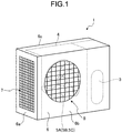
- FIG. 1 is a schematic view illustrating an outdoor unit having a "propeller fan according to the first example".
- an outdoor unit 1 of the first example is an outdoor unit of an air conditioner.
- the outdoor unit 1 has a housing 6. Inside the housing 6, a "compressor 3 for compressing a refrigerant", a “heat exchanger 4 that is coupled to the compressor 3 and through which the refrigerant flows", and a “propeller fan 5A that blows air to the heat exchanger 4" are housed.
- the housing 6 has an "inlet 7 for taking in outside air” and an “outlet 8 for exhausting the air in the housing 6".
- the inlet 7 is provided on the “side surface 6a and the back surface 6c of the housing 6".
- the outlet 8 is provided on the front surface 6b of the housing 6.
- the heat exchanger 4 is arranged over the "back surface 6c that faces the front surface 6b of the housing 6" and the side surface 6a.
- the propeller fan 5A is arranged so as to face the outlet 8 and is rotationally driven by a fan motor (not illustrated). In the following description, the direction of "the wind exhausted from the outlet 8 by the rotation of the propeller fan 5A" is the positive pressure side, and the opposite side is the negative pressure side.
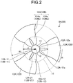
- FIG. 2 is a schematic plan view of the propeller fan according to the first example as viewed from the positive pressure side.
- the propeller fan 5A according to the first example has a hub 11 having a columnar shape (or a polygonal columnar shape) in appearance and a plurality of blades 12A.
- the plurality of blades 12A is provided on a "side surface 11a provided around the central axis of the hub 11".
- the hub 11 and the plurality of blades 12A are integrally formed by using "for example, a resin material as a forming material”.
- the blades are also called vanes.
- the hub 11 is formed in a columnar shape.
- the hub 11 has a "boss (not illustrated) into which a shaft (not illustrated) of the fan motor is fitted” at a position that is a central axis O.
- the hub 11 rotates in the "R" direction illustrated in the drawing with the "central axis O of the hub 11 in plan view” as an axis as the fan motor rotates.
- the boss (not illustrated) is provided on the negative pressure side (see FIG. 3 ).
- the plurality of (three in the example of FIG. 2 ) blades 12A is integrally formed with the hub 11 on the side surface 11a of the hub 11 at predetermined intervals along the circumferential direction of the hub 11.
- the blade 12A is formed in a plate shape.
- the propeller fan 5A has an "inner peripheral portion 12Aa and an outer peripheral portion 12Ab of the blade 12A" in plan view illustrated in FIG. 2 .
- the inner peripheral portion 12Aa is located within the circumference of a "circle having the central axis O and a radius r1".
- the outer peripheral portion 12Ab is located "outside the circumference of the 'circle having the central axis O and the radius r1' and within the circumference of a 'circle having the central axis O and a radius R1'".
- the "outer peripheral portion 12Ab extended in the radial direction of the hub 11" is formed to have a wider blade area.
- the ratio r1/R1 between the radius r1 and the radius R1 (hereinafter referred to as "radius ratio”) satisfies the following Formula (1). r 1 / R 1 ⁇ 0.4
- the propeller fan 5A has blade elements 12A-11 and 12A-12 on the inner peripheral portion 12Aa of each blade 12A in plan view illustrated in FIG. 2 . Further, the propeller fan 5A has a hole 12A-21 "between the blade element 12A-11 and the blade element 12A-12 of the inner peripheral portion 12Aa of each blade 12A" in the plan view illustrated in FIG. 2 .
- the hole 12A-21 is provided so as to "contact the boundary between the inner peripheral portion 12Aa and the outer peripheral portion 12Ab (position of the radius r1 from the central axis O)".
- each blade 12A is connected to the hub 11 such that "'a base 12A-11a of the blade element 12A-11 and a base 12A-12a of the blade element 12A-12" form the hole 12A-21 in the inner peripheral portion 12Aa".
- the outer peripheral portion 12Ab is continuous with the blade element 12A-11 and the blade element 12A-12.
- the inner peripheral portion 12Aa and the outer peripheral portion 12Ab form one blade surface.
- the base 12A-11a and the base 12A-12a are the base indicated in the claims. That is, the base 12A-11a and the base 12A-12a are "portions of the blade 12A that are connected to the hub 11".
- the two blade elements 12A-11 and 12A-12 are formed as "the blade 12A is divided on the way from the outer peripheral portion 12Ab of the blade 12A to the inner peripheral portion 12Aa".
- the hole 12A-21 "between the blade element 12A-11 and the blade element 12A-12” serves as a flow path of the airflow passing through the propeller fan 5A.
- FIG. 3 is a perspective view schematically illustrating the propeller fan according to the first example.
- FIG. 3 is a schematic enlarged perspective view of "one of 'the plurality of blades 12A illustrated in FIG. 2 '".
- the blade element 12A-12 located on the upstream side (the trailing edge side) in the rotation direction (the "R" direction in the drawing) is connected to the "positive pressure side as compared with the blade element 12A-11 located on the downstream side (leading edge side)” with respect to the hub 11.
- the hole 12A-21 of the blade 12A is located "between the blade element 12A-12 and the blade element 12A-11" with respect to the central axis O direction and the circumferential direction.
- the wind speed ratio V1/V2 which is "the ratio of the wind speed V1 at the outer peripheral portion 12Ab to the wind speed V2 at the inner peripheral portion 12Aa" satisfies the following Formula (3).
- Formula (3) is obtained by modifying Formula (2).
- the blade 12A may have three or more blade elements and two or more holes. That is, the outer peripheral portion 12Ab may be formed (configured) as one blade surface (for example, a blade surface without holes), and the inner peripheral portion 12Aa may include a plurality of blade elements arranged at a predetermined interval.
- FIG. 4 is a perspective view schematically illustrating the propeller fan according to the second example.
- the propeller fan 5B according to the second example is housed in the outdoor unit 1 illustrated in FIG. 1 .
- the "schematic plan view of the propeller fan 5B viewed from the positive pressure side" is similar to the "similar plan view regarding 'the propeller fan 5A according to the first example illustrated in FIG. 2 '". Therefore, in FIG. 2 , the reference numerals of the propeller fan 5B and the constituent elements according to the second example are illustrated in parentheses.
- FIG. 4 is a schematic enlarged perspective view of "one of the plurality of blades 12B illustrated in FIG. 2 ".
- the blade 12B has "an inner peripheral portion 12Ba, an outer peripheral portion 12Bb, a blade element 12B-11, a blade element 12B-12, a base 12B-11a, a base 12B-12a, and a hole 12B-21" similar to "the inner peripheral portion 12Aa, the outer peripheral portion 12Ab, the blade element 12A-11, the blade element 12A-12, the base 12A-11a, the base 12A-12a, and the hole 12A-21" of the blade 12A.
- the "blade element 12B-12 located on the upstream side in the rotation direction ("R" direction in the drawing)” and the “blade element 12B-11 located on the downstream side” are connected to "the same height position in the central axis O direction of the hub 11".
- the blade 12B may have three or more blade elements and two or more holes. That is, the outer peripheral portion 12Bb may be formed (configured) as one blade surface (for example, a blade surface without holes), and the inner peripheral portion 12Ba may include a plurality of blade elements arranged at a predetermined interval.
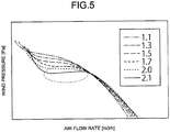
- FIG. 5 is a P-Q curve diagram.
- FIG. 5 illustrates "the basis for setting the radius ratio to 0.4 or less and the wind speed ratio V1/V2 to 2.0 or less in the propeller fans of the first example and the second example".
- an air flow rate Q [m3/h] is on the horizontal axis and a wind pressure P [Pa] is on the vertical axis.
- FIG. 5 illustrates P-Q curves for "the cases where the wind speed ratio V1/V2 is 1.1, 1.3, 1.5, 1.7, 2.0, and 2.1".
- FIG. 5 corresponds to "the propeller fan 5A (5B) having the plurality of blade elements 12A-11 and 12A-12 (12B-11 and 12B-12) in the inner peripheral portion 12Aa (12Ba)".
- the chord length length of a straight line connecting "one end and the other end of the blade element in the longitudinal direction of the cross section” of the blade elements 12A-11 and 12A-12 (12B-11 and 12B-12
- the minimum and maximum values of the cubic curve appear in the characteristics of the P-Q curve. This means that the surging phenomenon is occurring (see the portion surrounded by the broken lines in FIG. 5 ).
- the surging phenomenon occurs "when, in the blade 12A, the air blowing capacity of the inner peripheral portion 12Aa is lower than that of the outer peripheral portion 12Ab, and the difference between the wind speed at the inner peripheral portion 12Aa and the wind speed at the outer peripheral portion 12Ab (wind speed difference) becomes large".
- the surging phenomenon occurs in the flow rate range in which "the minimum value and the maximum value of the cubic curve appear in the P-Q characteristics of the propeller fan".
- the surging phenomenon is a phenomenon in which "'the pressure and flow rate' of the wind become unstable and largely fluctuate in the above flow rate range".
- FIG. 6 is a plan view of the propeller fan according to the third example as viewed from a positive pressure side.
- FIG. 7 is a plan view of "one of blades of 'the propeller fan according to the third example'" as viewed from a positive pressure side.
- FIG. 8 is a perspective view of "a vicinity of a root of a blade of 'the propeller fan according to the third example'” as viewed from the positive pressure side.
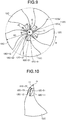
- FIG. 9 is a plan view of the propeller fan according to the third example as viewed from the negative pressure side.
- FIG. 10 is a perspective view of "one of blades of "the propeller fan according to the third example'” as viewed from the negative pressure side.
- FIG. 11 is a side view illustrating the propeller fan according to the third example.
- FIG. 12 is a perspective view illustrating the propeller fan according to the third example.
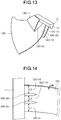
- FIG. 13 is a perspective view of "one of blades of 'the propeller fan according to the third example'”.
- FIG. 14 is a diagram schematically illustrating "each chord length and a total chord length" of the blade element. Note that similarly to “the propeller fan 5A according to the first example and the propeller fan 5B according to the second example", the propeller fan 5C according to the third example is housed in the outdoor unit 1 illustrated in FIG. 1 .
- the propeller fan 5C according to the third example has a hub 11 having a columnar shape and "a plurality of blades 12C provided on the side surface of the hub 11".
- the hub 11 and the plurality of blades 12C are integrally formed by using "for example, a resin material as a forming material”.
- the plurality of (five in the third example) blades 12C is integrally formed with the hub 11 on the side surface 11a of the hub 11 at predetermined intervals along the circumferential direction of the hub 11.
- the blade 12C is formed in a plate shape.
- the propeller fan 5C has an "inner peripheral portion 12Ca and an outer peripheral portion 12Cb of the blade 12C" in plan view illustrated in FIG. 6 .
- the inner peripheral portion 12Ca is located within the circumference of a "circle having the central axis O and a radius r3".
- the outer peripheral portion 12Cb is located "outside the circumference of the 'circle having the central axis O and the radius r3' and within the circumference of a 'circle having a radius R3 of the propeller fan 5C'". As illustrated in FIG.
- the "outer peripheral portion 12Cb extended in the radial direction of the hub 11” is formed to have a wider blade area.
- the trailing edge portion 12C-1 which is 'the upstream side in the rotation direction of the blade 12C (the direction of the "R” illustrated in FIG. 6 )'
- the trailing edge portion 12C-1 is curved as viewed from the rotation axis direction of the central axis O.
- the surface (blade surface) of the blade 12C is formed to "gently curve from the trailing edge portion 12C-1 to the leading edge portion 12C-2 from the negative pressure side to the positive pressure side of the propeller fan 5C in the circumferential direction of the hub 11" (see, for example, FIG. 9 ).
- the "propeller fan 5C having such blades 12C” in the R direction (the "R" direction illustrated in FIG. 6 )
- the amount of the "air flowing from the negative pressure side to the positive pressure side” increases.
- the ratio r3/R3 (radius ratio) of the radius r3 and the radius R3 satisfies the following Formula (4) . r 3 / R 3 ⁇ 0.7
- the propeller fan 5C has three blade elements 12C-11, 12C-12, and 12C-13 on the inner peripheral portion 12Ca of each blade 12C. Further, the propeller fan 5C has, for example, as illustrated in detail in FIG. 8 , a hole 12C-21 "between the blade element 12C-11 and the blade element 12C-12 of the inner peripheral portion 12Ca of each blade 12C". Further, the propeller fan 5C has a hole 12C-22 "between the blade element 12C-12 and the blade element 12C-13 of the inner peripheral portion 12Ca of each blade 12C".
- each blade 12C is connected to the hub 11 such that "'a base 12C-11a of the blade element 12C-11, a base 12C-12a of the blade element 12C-12, and a base 12C-13a of the blade element 12C-13" form the holes 12C-21 and 12C-22 in the inner peripheral portion 12Ca".
- the outer peripheral portion 12Cb is continuous with "the blade elements 12C-11, 12C-12, and 12C-13".
- the inner peripheral portion 12Ca and the outer peripheral portion 12Cb form one blade surface.
- “the base 12C-11a, the base 12C-12a, and the base 12C-13a” are the base indicated in the claims. That is, “the base 12C-11a, the base 12C-12a, and the base 12C-13a" are "portions of the blade 12C that are connected to the hub 11".
- the three blade elements 12C-11, 12C-12, and 12C-13 are formed as "the blade 12C is divided on the way from the outer peripheral portion 12Cb of the blade 12C to the inner peripheral portion 12Ca".
- the hole 12C-21 between 'the blade element 12C-11 and the blade element 12C-12' and the hole 12C-22 between 'the blade element 12C-12 and the blade element 12C-13' serve as flow paths for the airflow passing through the propeller fan 5C.
- the base 12C-13a of "the blade element 12C-13 located on the most upstream side (trailing edge side) in the rotation direction (the "R” direction in the drawing)” is, as compared with "'the base 12C-12a of the blade element 12C-12' and 'the base 12C-11a of the blade element 12C-11' located on the downstream side (leading edge side)", connected to the "positive pressure side relative to the central axis O direction" with respect to the hub 11.
- the base 12C-12a of the blade element 12C-12 is connected to the "positive pressure side relative to the central axis O direction" of the hub 11 as compared with “the base 12C-11a of the blade element 12C-11".
- the hole 12C-21 of the blade 12C is located “between the blade element 12C-12 and the blade element 12C-11” with respect to the central axis O direction and the circumferential direction.
- the hole 12C-22 of the blade 12C is located "between the blade element 12C-13 and the blade element 12C-12" with respect to the central axis O direction and the circumferential direction.
- the respective chord lengths of the blade elements 12C-11 to 12C-13 are L1 [mm], L2 [mm], and L3 [mm], and the size relation of L1 ⁇ L2 ⁇ L3 is established.
- Lmin is L1 and L0 is L1 + L2 + L3, and from the above Formula (5), L1/(L1 + L2 + L3) ⁇ 0.1 is established.
- FIGS. 6 to 14 illustrate an aspect in which "the holes 12C-21 and 12C-22 extend to the hub 11".
- the "shape, aspect, or the like of the holes 12C-21 and 12C-22" can be appropriately changed.
- an aspect is also possible in which "the holes 12C-21 and 12C-22 reach the positions separated from the hub 11 by a predetermined distance”.
- the blade 12C may have two blade elements and one hole.
- the blade 12C may have four or more blade elements and three or more holes. That is, the outer peripheral portion 12Cb may be formed of one blade surface, and the inner peripheral portion 12Ca may include "at least one hole” and "a plurality of blade elements formed across the hole”.
- the holes 12C-21 and 12C-22 may be formed in a range "from the boundary between the inner peripheral portion 12Ca and the outer peripheral portion 12Cb to the side surface of the hub 11 in the radial direction". Further, the holes 12C-21 and 12C-22 may be formed so as to "contact both the above-mentioned boundary and the side surface of the hub 11".
- FIG. 15 is a graph (curve diagram) illustrating the relationship between radius ratio and "air flow rate and efficiency".
- FIG. 16 is a graph (curve diagram) illustrating the relationship between "'minimum chord length of blade element/total chord length of blade element'" and "air flow rate and the efficiency”.
- FIG. 15 illustrates the reason why the radius ratio is 0.7 or less in the third example. Further, FIG. 16 illustrates the reason why the minimum chord length of the blade element/the total chord length of the blade element is 0.1 or more in the third example.
- air flow rate Q11 and efficiency ⁇ 11 correspond to "the air flow rate and the efficiency when 'the propeller fan 5C rotates at a rated load of the air conditioner'".
- air flow rate Q12 and efficiency ⁇ 12 correspond to "the air flow rate and the efficiency when 'the propeller fan 5C rotates at a load higher than the rated load of the air conditioner'". It is preferable that the efficiencies ⁇ 11 and ⁇ 12 do not drop extremely below the peak value at both the rated load and the high load.
- the efficiencies ⁇ 11 and ⁇ 12 illustrate peak values. Therefore, at the rated load, in the case of the radius ratio of r3/R3 ⁇ 0.7, the efficiency ⁇ 11 of the propeller fan 5C falls within the range "from the peak value to about -10% or less of the peak value". Further, in the case of the radius ratio of r3/R3 ⁇ 0.5 under a high load, the "air flow rate Q12 and efficiency ⁇ 12" of the propeller fan 5C became the highest.
- air flow rate Q21 and efficiency ⁇ 21 correspond to "the air flow rate and the efficiency when 'the propeller fan 5C rotates at a rated load of the air conditioner'".
- air flow rate Q22 and efficiency ⁇ 22 correspond to "the air flow rate and the efficiency when 'the propeller fan 5C rotates at a load higher than the rated load of the air conditioner'".
- the wind speed at the inner peripheral portions 12Aa, 12Ba, and 12Ca can be improved without depending on the improvement of "the wind speed at 'the respective outer peripheral portions 12Ab, 12Bb, and 12Cb of the blades 12A, 12B, and 12C'". Therefore, it is possible to suppress the difference (wind speed difference) between the wind speed at the "outer peripheral portions 12Ab, 12Bb, and 12Cb" and the wind speed at the "inner peripheral portions 12Aa, 12Ba, and 12Ca".
Landscapes
- Engineering & Computer Science (AREA)
- Mechanical Engineering (AREA)
- General Engineering & Computer Science (AREA)
- Structures Of Non-Positive Displacement Pumps (AREA)
- Air-Conditioning For Vehicles (AREA)
Abstract
Description
- The present invention relates to a propeller fan. Background
- For example, an air conditioner has a propeller fan in its outdoor unit. The wind speed in the propeller fan is high at the outer peripheral portion of the blade and decreases toward the center of rotation. In recent years, in order to improve the energy saving performance of air conditioners, the air flow rate of propeller fans has been improved. Specifically, the "increase in diameter and high speed rotation" of propeller fans have been carried out.
- Note that the technology in this field is disclosed in, for example, Japanese Laid-open Patent Publication No.
2010-101223 WO 2011/011890 , Japanese Laid-open Patent Publication No.2003-503643 2004-116511 -
- Patent Literature 1: Japanese Laid-open Patent Publication No.
2010-101223 - Patent Literature 2: International Publication No.
WO 2011/0011890 - Patent Literature 3: Japanese Laid-open Patent Publication No.
2003-503643 - Patent Literature 4: Japanese Laid-open Patent Publication No.
2004-116511 - In the general technology, the wind speed distribution in the radial direction of the blade becomes non-uniform. Therefore, a surging phenomenon such as sucking air from a downstream side occurs in the inner peripheral portion of the blade, and the operating state becomes abnormal. When a propeller fan is used in an outdoor unit, the surging phenomenon may lead to noise and damage to the propeller fan. Also, the "inner peripheral portion of the propeller fan where the wind speed is slow" does not substantially contribute to the air blowing. For this reason, it can be said that the "air blowing rate obtained for the size of the propeller fan" is small and the blade surface is not effectively used.
- One object of the present disclosure is to provide a "propeller fan and an outdoor unit of an air conditioner" capable of "improving the air flow rate of the propeller fan while suppressing a 'difference between the wind speed at the outer peripheral portion and the wind speed at the inner peripheral portion (wind speed difference) of the blade'".
- According to an aspect of an embodiment, a propeller fan includes a hub that has a side surface around a central axis, and a plurality of blades that are provided on the side surface of the hub, wherein a blade includes an inner peripheral portion that is located on a side of a base connected to the hub of the blade, and an outer peripheral portion that is located on a side of an outer edge of the blade, the outer peripheral portion is formed as one blade surface, the inner peripheral portion includes a plurality of blade elements arranged at a predetermined interval, a ratio r/R in which a radius r which is a distance from the central axis to a boundary between the inner peripheral portion and the outer peripheral portion and a radius R which is a distance from the central axis to the outer edge of the blade is 0.4 or less, and when a wind speed at the outer peripheral portion is V1 and a wind speed at the inner peripheral portion is V2, a relational formula of V1 ≤ V2 × 2.0 is established.
- According to one aspect of the present disclosure, it is possible to improve the air flow rate of the propeller fan while suppressing a difference between the wind speed at the outer peripheral portion and the wind speed at the inner peripheral portion (central portion) of the blade.
-
-
FIG. 1 is a schematic view illustrating an outdoor unit having a propeller fan according to a first example (second and third examples). -
FIG. 2 is a schematic plan view of the fan according to the first example (second example) as viewed from a positive pressure side. -
FIG. 3 is a perspective view schematically illustrating the propeller fan according to the first example. -
FIG. 4 is a perspective view schematically illustrating the propeller fan according to the second example. -
FIG. 5 is a P-Q curve diagram. -
FIG. 6 is a plan view of the propeller fan according to the third example as viewed from a positive pressure side. -
FIG. 7 is a plan view of one of blades of the propeller fan according to the third example as viewed from a positive pressure side. -
FIG. 8 is a perspective view of a vicinity of a root of a blade of the propeller fan according to the third example as viewed from the positive pressure side. -
FIG. 9 is a plan view of the propeller fan according to the third example as viewed from a negative pressure side. -
FIG. 10 is a perspective view of one of blades of the propeller fan according to the third example as viewed from the negative pressure side. -
FIG. 11 is a side view illustrating the propeller fan according to the third example. -
FIG. 12 is a perspective view illustrating the propeller fan according to the third example. -
FIG. 13 is a perspective view of one of blades of the propeller fan according to the third example. -
FIG. 14 is a diagram schematically illustrating each chord length and a total chord length of a blade element. -
FIG. 15 is a curve diagram illustrating the relationship between radius ratio and air flow rate and efficiency. -
FIG. 16 is a curve diagram illustrating the relationship between a minimum chord length of a blade element/a total chord length of a blade element and air flow rate and the efficiency. - Modes for carrying out the present disclosure will be described in detail below with reference to the drawings. The technology of the present disclosure is not limited by various embodiments described below. Further, the various embodiments described below may be appropriately combined and carried out within a range where they do not contradict. Note that the description of the already-explained elements is omitted.
-
FIG. 1 is a schematic view illustrating an outdoor unit having a "propeller fan according to the first example". As illustrated inFIG. 1 , anoutdoor unit 1 of the first example is an outdoor unit of an air conditioner. Theoutdoor unit 1 has ahousing 6. Inside thehousing 6, a "compressor 3 for compressing a refrigerant", a "heat exchanger 4 that is coupled to thecompressor 3 and through which the refrigerant flows", and a "propeller fan 5A that blows air to theheat exchanger 4" are housed. - The
housing 6 has an "inlet 7 for taking in outside air" and an "outlet 8 for exhausting the air in thehousing 6". Theinlet 7 is provided on the "side surface 6a and theback surface 6c of thehousing 6". Theoutlet 8 is provided on thefront surface 6b of thehousing 6. Theheat exchanger 4 is arranged over the "back surface 6c that faces thefront surface 6b of thehousing 6" and theside surface 6a. Thepropeller fan 5A is arranged so as to face theoutlet 8 and is rotationally driven by a fan motor (not illustrated). In the following description, the direction of "the wind exhausted from theoutlet 8 by the rotation of thepropeller fan 5A" is the positive pressure side, and the opposite side is the negative pressure side. -
FIG. 2 is a schematic plan view of the propeller fan according to the first example as viewed from the positive pressure side. As illustrated inFIG. 2 , thepropeller fan 5A according to the first example has ahub 11 having a columnar shape (or a polygonal columnar shape) in appearance and a plurality ofblades 12A. The plurality ofblades 12A is provided on a "side surface 11a provided around the central axis of thehub 11". Thehub 11 and the plurality ofblades 12A are integrally formed by using "for example, a resin material as a forming material". The blades are also called vanes. Thehub 11 is formed in a columnar shape. Thehub 11 has a "boss (not illustrated) into which a shaft (not illustrated) of the fan motor is fitted" at a position that is a central axis O. Thehub 11 rotates in the "R" direction illustrated in the drawing with the "central axis O of thehub 11 in plan view" as an axis as the fan motor rotates. The boss (not illustrated) is provided on the negative pressure side (seeFIG. 3 ). The plurality of (three in the example ofFIG. 2 )blades 12A is integrally formed with thehub 11 on theside surface 11a of thehub 11 at predetermined intervals along the circumferential direction of thehub 11. Theblade 12A is formed in a plate shape. - The
propeller fan 5A has an "inner peripheral portion 12Aa and an outer peripheral portion 12Ab of theblade 12A" in plan view illustrated inFIG. 2 . The inner peripheral portion 12Aa is located within the circumference of a "circle having the central axis O and a radius r1". The outer peripheral portion 12Ab is located "outside the circumference of the 'circle having the central axis O and the radius r1' and within the circumference of a 'circle having the central axis O and a radius R1'". As illustrated inFIG. 2 , as compared with the "inner peripheral portion 12Aa coupled to thehub 11", the "outer peripheral portion 12Ab extended in the radial direction of thehub 11" is formed to have a wider blade area. Here, the ratio r1/R1 between the radius r1 and the radius R1 (hereinafter referred to as "radius ratio") satisfies the following Formula (1).
- For example, the radius ratio r1/R1 = 0.4 means that "'the boundary between the inner peripheral portion 12Aa and the outer peripheral portion 12Ab of the
blade 12A' defined by 'the radius r1 from the central axis O' lies in the "position 0.4 times the length of the radius R1 from the central axis O'". Note that in the present example, r1 = 88 [mm] (φ = 176) and radius R1 = 220 [mm] (φ = 440) are set as an example. - Further, the
propeller fan 5A hasblade elements 12A-11 and 12A-12 on the inner peripheral portion 12Aa of eachblade 12A in plan view illustrated inFIG. 2 . Further, thepropeller fan 5A has ahole 12A-21 "between theblade element 12A-11 and theblade element 12A-12 of the inner peripheral portion 12Aa of eachblade 12A" in the plan view illustrated inFIG. 2 . Thehole 12A-21 is provided so as to "contact the boundary between the inner peripheral portion 12Aa and the outer peripheral portion 12Ab (position of the radius r1 from the central axis O)". That is, eachblade 12A is connected to thehub 11 such that "'abase 12A-11a of theblade element 12A-11 and abase 12A-12a of theblade element 12A-12" form thehole 12A-21 in the inner peripheral portion 12Aa". The outer peripheral portion 12Ab is continuous with theblade element 12A-11 and theblade element 12A-12. The inner peripheral portion 12Aa and the outer peripheral portion 12Ab form one blade surface. In the present example, thebase 12A-11a and thebase 12A-12a are the base indicated in the claims. That is, thebase 12A-11a and thebase 12A-12a are "portions of theblade 12A that are connected to thehub 11". - In other words, the two
blade elements 12A-11 and 12A-12 are formed as "theblade 12A is divided on the way from the outer peripheral portion 12Ab of theblade 12A to the inner peripheral portion 12Aa". Thehole 12A-21 "between theblade element 12A-11 and theblade element 12A-12" serves as a flow path of the airflow passing through thepropeller fan 5A. -
FIG. 3 is a perspective view schematically illustrating the propeller fan according to the first example.FIG. 3 is a schematic enlarged perspective view of "one of 'the plurality ofblades 12A illustrated inFIG. 2 '". As illustrated inFIG. 3 , in theblade 12A, "theblade element 12A-12 located on the upstream side (the trailing edge side) in the rotation direction (the "R" direction in the drawing) is connected to the "positive pressure side as compared with theblade element 12A-11 located on the downstream side (leading edge side)" with respect to thehub 11. Then, thehole 12A-21 of theblade 12A is located "between theblade element 12A-12 and theblade element 12A-11" with respect to the central axis O direction and the circumferential direction. - Then, when the maximum wind speed at the outer peripheral portion 12Ab is V1 [m/s] and the maximum wind speed at the inner peripheral portion 12Aa is V2 [m/s] when the
propeller fan 5A rotates, the following Formula (2) is established.
- In other words, the wind speed ratio V1/V2, which is "the ratio of the wind speed V1 at the outer peripheral portion 12Ab to the wind speed V2 at the inner peripheral portion 12Aa", satisfies the following Formula (3). Formula (3) is obtained by modifying Formula (2).

- Note that the numbers of "
blade elements 12A-11 and 12A-12 andholes 12A-21 of the 'blade 12A of the first example'" are not limited to the numbers illustrated inFIGS. 2 and3 . Theblade 12A may have three or more blade elements and two or more holes. That is, the outer peripheral portion 12Ab may be formed (configured) as one blade surface (for example, a blade surface without holes), and the inner peripheral portion 12Aa may include a plurality of blade elements arranged at a predetermined interval. -
FIG. 4 is a perspective view schematically illustrating the propeller fan according to the second example. Similarly to thepropeller fan 5A according to the first example, thepropeller fan 5B according to the second example is housed in theoutdoor unit 1 illustrated inFIG. 1 . Further, the "schematic plan view of thepropeller fan 5B viewed from the positive pressure side" is similar to the "similar plan view regarding 'thepropeller fan 5A according to the first example illustrated inFIG. 2 '". Therefore, inFIG. 2 , the reference numerals of thepropeller fan 5B and the constituent elements according to the second example are illustrated in parentheses. -
FIG. 4 is a schematic enlarged perspective view of "one of the plurality ofblades 12B illustrated inFIG. 2 ". As illustrated inFIG. 4 , theblade 12B has "an inner peripheral portion 12Ba, an outer peripheral portion 12Bb, ablade element 12B-11, ablade element 12B-12, abase 12B-11a, abase 12B-12a, and ahole 12B-21" similar to "the inner peripheral portion 12Aa, the outer peripheral portion 12Ab, theblade element 12A-11, theblade element 12A-12, thebase 12A-11a, thebase 12A-12a, and thehole 12A-21" of theblade 12A. However, in theblade 12B, the "blade element 12B-12 located on the upstream side in the rotation direction ("R" direction in the drawing)" and the "blade element 12B-11 located on the downstream side" are connected to "the same height position in the central axis O direction of thehub 11". - Then, also in the
blade 12B according to the second example, as in theblade 12A according to the first example, the above Formulae (1) to (3) are established. - Note that the numbers of "
blade elements 12B-11 and 12B-12 and holes 12B-21 of the 'blade 12B of the second example'" are not limited to the numbers illustrated inFIGS. 2 and4 . Theblade 12B may have three or more blade elements and two or more holes. That is, the outer peripheral portion 12Bb may be formed (configured) as one blade surface (for example, a blade surface without holes), and the inner peripheral portion 12Ba may include a plurality of blade elements arranged at a predetermined interval. -
FIG. 5 is a P-Q curve diagram.FIG. 5 illustrates "the basis for setting the radius ratio to 0.4 or less and the wind speed ratio V1/V2 to 2.0 or less in the propeller fans of the first example and the second example". InFIG. 5 , an air flow rate Q [m3/h] is on the horizontal axis and a wind pressure P [Pa] is on the vertical axis. - Here,
FIG. 5 illustrates P-Q curves for "the cases where the wind speed ratio V1/V2 is 1.1, 1.3, 1.5, 1.7, 2.0, and 2.1".FIG. 5 corresponds to "thepropeller fan 5A (5B) having the plurality ofblade elements 12A-11 and 12A-12 (12B-11 and 12B-12) in the inner peripheral portion 12Aa (12Ba)". In the propeller fan for each data, the chord length (length of a straight line connecting "one end and the other end of the blade element in the longitudinal direction of the cross section") of theblade elements 12A-11 and 12A-12 (12B-11 and 12B-12) is adjusted such that "the wind speed ratio V1/V2 becomes the above numerical value". In the propeller fan with the wind speed ratio V1/V2 of 2.1, the minimum and maximum values of the cubic curve appear in the characteristics of the P-Q curve. This means that the surging phenomenon is occurring (see the portion surrounded by the broken lines inFIG. 5 ). - Here, the surging phenomenon occurs "when, in the
blade 12A, the air blowing capacity of the inner peripheral portion 12Aa is lower than that of the outer peripheral portion 12Ab, and the difference between the wind speed at the inner peripheral portion 12Aa and the wind speed at the outer peripheral portion 12Ab (wind speed difference) becomes large". The surging phenomenon occurs in the flow rate range in which "the minimum value and the maximum value of the cubic curve appear in the P-Q characteristics of the propeller fan". The surging phenomenon is a phenomenon in which "'the pressure and flow rate' of the wind become unstable and largely fluctuate in the above flow rate range". When the propeller fan is operated within the "flow rate range in which this phenomenon occurs", vibration and/or back flow occurs. As a result, normal operation becomes difficult due to occurrence of "abnormal noise and/or pressure pulsation". - On the other hand, in the case of the wind speed ratio V1/V2 ≤ 2.0, the smaller the wind speed ratio V1/V2 is, the more smooth the P-Q curve is, the surging phenomenon does not occur, and the air flow rate can be improved.
- From the above, it has been found that when the wind speed ratio V1/V2 exceeds 2.0, a surging region occurs depending on the blade shape. On the other hand, it has been found that when the wind speed ratio V1/V2 is 2.0 or less, the occurrence of the surging region can be suppressed regardless of the blade shape.
- Note that, regarding the relationship between the air flow rate [m3/h] and the input [W], as compared with "the propeller fan with the wind speed ratio V1/V2 of 2.1", in the case of the "propeller fan with the wind speed ratio V1/V2 ≤ 2.0", the "input power for outputting the same air flow rate (power input to a fan motor, which is not illustrated, for driving the propeller fan)" can be small. Also, when the input power is the same, the larger the wind speed ratio V1/V2, the larger the air flow rate. Further, regarding the relationship between the air flow rate [m3/h] and the rotation rate [rpm], as compared with the "propeller fan with the wind speed ratio V1/V2 = 2.1", in the case of the "propeller fan propeller fan with the wind speed ratio V1/V2 ≤ 2.0", the rotation rate for obtaining the same air flow rate can be small. Also, the larger the wind speed ratio V1/V2, the larger the air flow rate.
- From the above, in the first example and the second example, when the
propeller fans -
FIG. 6 is a plan view of the propeller fan according to the third example as viewed from a positive pressure side.FIG. 7 is a plan view of "one of blades of 'the propeller fan according to the third example'" as viewed from a positive pressure side.FIG. 8 is a perspective view of "a vicinity of a root of a blade of 'the propeller fan according to the third example'" as viewed from the positive pressure side. Further,FIG. 9 is a plan view of the propeller fan according to the third example as viewed from the negative pressure side.FIG. 10 is a perspective view of "one of blades of "the propeller fan according to the third example'" as viewed from the negative pressure side. - Further,
FIG. 11 is a side view illustrating the propeller fan according to the third example.FIG. 12 is a perspective view illustrating the propeller fan according to the third example.FIG. 13 is a perspective view of "one of blades of 'the propeller fan according to the third example'".FIG. 14 is a diagram schematically illustrating "each chord length and a total chord length" of the blade element. Note that similarly to "thepropeller fan 5A according to the first example and thepropeller fan 5B according to the second example", thepropeller fan 5C according to the third example is housed in theoutdoor unit 1 illustrated inFIG. 1 . - As illustrated in
FIGS. 6 to 14 , thepropeller fan 5C according to the third example has ahub 11 having a columnar shape and "a plurality ofblades 12C provided on the side surface of thehub 11". Thehub 11 and the plurality ofblades 12C are integrally formed by using "for example, a resin material as a forming material". The plurality of (five in the third example)blades 12C is integrally formed with thehub 11 on theside surface 11a of thehub 11 at predetermined intervals along the circumferential direction of thehub 11. Theblade 12C is formed in a plate shape. - The
propeller fan 5C has an "inner peripheral portion 12Ca and an outer peripheral portion 12Cb of theblade 12C" in plan view illustrated inFIG. 6 . The inner peripheral portion 12Ca is located within the circumference of a "circle having the central axis O and a radius r3". The outer peripheral portion 12Cb is located "outside the circumference of the 'circle having the central axis O and the radius r3' and within the circumference of a 'circle having a radius R3 of thepropeller fan 5C'". As illustrated inFIG. 6 , as compared with the "inner peripheral portion 12Ca coupled to thehub 11", the "outer peripheral portion 12Cb extended in the radial direction of thehub 11" is formed to have a wider blade area. In theblade 12C, "the trailingedge portion 12C-1 which is 'the upstream side in the rotation direction of theblade 12C (the direction of the "R" illustrated inFIG. 6 )'" is formed to curve toward the "leadingedge portion 12C-2 located on the opposite side of the trailingedge portion 12C-1'" (see alsoFIG. 11 ). The trailingedge portion 12C-1 is curved as viewed from the rotation axis direction of the central axis O. - Then, the surface (blade surface) of the
blade 12C is formed to "gently curve from the trailingedge portion 12C-1 to theleading edge portion 12C-2 from the negative pressure side to the positive pressure side of thepropeller fan 5C in the circumferential direction of thehub 11" (see, for example,FIG. 9 ). By rotating the "propeller fan 5C havingsuch blades 12C" in the R direction (the "R" direction illustrated inFIG. 6 ), air flows from the negative pressure side to the positive pressure side. As the rotation rate of thepropeller fan 5C increases, the amount of the "air flowing from the negative pressure side to the positive pressure side" increases. - Here, the ratio r3/R3 (radius ratio) of the radius r3 and the radius R3 satisfies the following Formula (4) .

- For example, the radius ratio r3/R3 = 0.7 means that "'the boundary between the inner peripheral portion 12Ca and the outer peripheral portion 12Cb of the
blade 12C' defined by 'the radius r3 from the central axis O' lies in the "position 0.7 times the length of the radius R3 from the central axis O'". - Further, as illustrated in
FIGS. 8 to 14 , thepropeller fan 5C has threeblade elements 12C-11, 12C-12, and 12C-13 on the inner peripheral portion 12Ca of eachblade 12C. Further, thepropeller fan 5C has, for example, as illustrated in detail inFIG. 8 , ahole 12C-21 "between theblade element 12C-11 and theblade element 12C-12 of the inner peripheral portion 12Ca of eachblade 12C". Further, thepropeller fan 5C has ahole 12C-22 "between theblade element 12C-12 and theblade element 12C-13 of the inner peripheral portion 12Ca of eachblade 12C". That is, eachblade 12C is connected to thehub 11 such that "'abase 12C-11a of theblade element 12C-11, abase 12C-12a of theblade element 12C-12, and abase 12C-13a of theblade element 12C-13" form theholes 12C-21 and 12C-22 in the inner peripheral portion 12Ca". The outer peripheral portion 12Cb is continuous with "theblade elements 12C-11, 12C-12, and 12C-13". The inner peripheral portion 12Ca and the outer peripheral portion 12Cb form one blade surface. In the present example, "thebase 12C-11a, thebase 12C-12a, and thebase 12C-13a" are the base indicated in the claims. That is, "thebase 12C-11a, thebase 12C-12a, and thebase 12C-13a" are "portions of theblade 12C that are connected to thehub 11". - In other words, the three
blade elements 12C-11, 12C-12, and 12C-13 are formed as "theblade 12C is divided on the way from the outer peripheral portion 12Cb of theblade 12C to the inner peripheral portion 12Ca". "Thehole 12C-21 between 'theblade element 12C-11 and theblade element 12C-12' and thehole 12C-22 between 'theblade element 12C-12 and theblade element 12C-13'" serve as flow paths for the airflow passing through thepropeller fan 5C. - For example, as illustrated in
FIGS. 7 and8 , in oneblade 12C, thebase 12C-13a of "theblade element 12C-13 located on the most upstream side (trailing edge side) in the rotation direction (the "R" direction in the drawing)" is, as compared with "'thebase 12C-12a of theblade element 12C-12' and 'thebase 12C-11a of theblade element 12C-11' located on the downstream side (leading edge side)", connected to the "positive pressure side relative to the central axis O direction" with respect to thehub 11. Further, "thebase 12C-12a of theblade element 12C-12" is connected to the "positive pressure side relative to the central axis O direction" of thehub 11 as compared with "thebase 12C-11a of theblade element 12C-11". Then, thehole 12C-21 of theblade 12C is located "between theblade element 12C-12 and theblade element 12C-11" with respect to the central axis O direction and the circumferential direction. Thehole 12C-22 of theblade 12C is located "between theblade element 12C-13 and theblade element 12C-12" with respect to the central axis O direction and the circumferential direction. - Then, when the total chord length, which is the sum of the "chord lengths of the
blade elements 12C-11 to 12C-13 of the inner peripheral portion 12Ca," is set to L0 [mm], and "the minimum chord length of each chord length of theblade elements 12C-11 to 12C-13 (the length of the straight line connecting 'one end and the other end of the blade element in the longitudinal direction of the cross section') is set to Lmin [mm], the following Formula (5) is established.
- For example, as illustrated in
FIG. 14 , the respective chord lengths of theblade elements 12C-11 to 12C-13 are L1 [mm], L2 [mm], and L3 [mm], and the size relation of L1 < L2 < L3 is established. At this time, Lmin is L1 and L0 is L1 + L2 + L3, and from the above Formula (5), L1/(L1 + L2 + L3) ≥ 0.1 is established. - Further,
FIGS. 6 to 14 illustrate an aspect in which "theholes 12C-21 and 12C-22 extend to thehub 11". However, when the above Formulae (4) to (6) are satisfied, the "shape, aspect, or the like of theholes 12C-21 and 12C-22" can be appropriately changed. For example, an aspect is also possible in which "theholes 12C-21 and 12C-22 reach the positions separated from thehub 11 by a predetermined distance". - As will be described later, in the third example, when the
propeller fan 5C satisfies "the conditions of the radius ratio r3/R3 ≤ 0.7 and Lmin/L0 ≥ 0.1", surging is less likely to occur, and the air flow rate can be improved. - Note that the numbers of the "
blade elements 12C-11 to 12C-13 andholes 12C-21 and 12C-22 of the 'blade 12C of the third example'" are not limited to the numbers illustrated inFIGS. 8 to 13 . Theblade 12C may have two blade elements and one hole. Alternatively, theblade 12C may have four or more blade elements and three or more holes. That is, the outer peripheral portion 12Cb may be formed of one blade surface, and the inner peripheral portion 12Ca may include "at least one hole" and "a plurality of blade elements formed across the hole". Further, theholes 12C-21 and 12C-22 may be formed in a range "from the boundary between the inner peripheral portion 12Ca and the outer peripheral portion 12Cb to the side surface of thehub 11 in the radial direction". Further, theholes 12C-21 and 12C-22 may be formed so as to "contact both the above-mentioned boundary and the side surface of thehub 11". -
FIG. 15 is a graph (curve diagram) illustrating the relationship between radius ratio and "air flow rate and efficiency".FIG. 16 is a graph (curve diagram) illustrating the relationship between "'minimum chord length of blade element/total chord length of blade element'" and "air flow rate and the efficiency".FIG. 15 illustrates the reason why the radius ratio is 0.7 or less in the third example. Further,FIG. 16 illustrates the reason why the minimum chord length of the blade element/the total chord length of the blade element is 0.1 or more in the third example. - In
FIG. 15 , the radius ratio is on the horizontal axis, and air flow rate Q [m3/h] and efficiency η (= air flow rate Q/input) [m3/h/W] is on the vertical axis. InFIG. 15 , air flow rate Q11 and efficiency η11 correspond to "the air flow rate and the efficiency when 'thepropeller fan 5C rotates at a rated load of the air conditioner'". On the other hand, air flow rate Q12 and efficiency η12 correspond to "the air flow rate and the efficiency when 'thepropeller fan 5C rotates at a load higher than the rated load of the air conditioner'". It is preferable that the efficiencies η11 and η12 do not drop extremely below the peak value at both the rated load and the high load. - In
FIG. 15 , in the case of the radius ratio of r3/R3 ≤ 0.4 to 0.5, the efficiencies η11 and η12 illustrate peak values. Therefore, at the rated load, in the case of the radius ratio of r3/R3 ≤ 0.7, the efficiency η11 of thepropeller fan 5C falls within the range "from the peak value to about -10% or less of the peak value". Further, in the case of the radius ratio of r3/R3 ≤ 0.5 under a high load, the "air flow rate Q12 and efficiency η12" of thepropeller fan 5C became the highest. - Further, in
FIG. 16 , "minimum chord length of base of blade element/total chord length of blade element (= Lmin/L0)" is on the horizontal axis, and air flow rate Q [m3/h] and efficiency η [m3/h/W] is on the vertical axis. InFIG. 16 , air flow rate Q21 and efficiency η21 correspond to "the air flow rate and the efficiency when 'thepropeller fan 5C rotates at a rated load of the air conditioner'". On the other hand, air flow rate Q22 and efficiency η22 correspond to "the air flow rate and the efficiency when 'thepropeller fan 5C rotates at a load higher than the rated load of the air conditioner'". - As illustrated in
FIG. 16 , regarding the efficiency η21 at the rated load, the amount of reduction in efficiency η21 at the rated load in the "total region of the minimum chord length of blade element/total chord length of blade element (= Lmin/L0)" is as small as "10% of the peak value". Therefore, there is no particular limitation on the "minimum chord length of blade element/total chord length of blade element (= Lmin/L0)". On the other hand, inFIG. 16 , at the high load, in the case of "minimum chord length of blade element/total chord length of blade element (= Lmin/L0) < 0.1", the reduction rate of air flow rate Q21 is 40% or more of the peak value. From this reason, the minimum chord length of the blade element/total chord length of the blade element (= Lmin/L0) ≥ 0.1. - Therefore, according to the above-mentioned first to third examples, "the wind speed at the inner peripheral portions 12Aa, 12Ba, and 12Ca" can be improved without depending on the improvement of "the wind speed at 'the respective outer peripheral portions 12Ab, 12Bb, and 12Cb of the
blades propeller fans - The embodiments have been described above. However, the technology disclosed in the present application is not limited to the above content. Further, the above-described constituent elements include "those that can be easily assumed by those skilled in the art, substantially the same, and so-called equivalent ranges". Furthermore, the constituent elements described above can be combined as appropriate. Furthermore, at least one of "various omissions, replacements, and changes of constituent elements" can be performed without departing from the spirit of the embodiments.
- Note that the radius ratio r1/R1 = 0.4 may mean that, in the
blade 12A, on the assumption that the radius R1 from the central axis O is 1 with respect to the boundary between the inner peripheral portion 12Aa and the outer peripheral portion 12Ab, the radius r1 from the central axis O lies in the position 0.4 times the length of the radius R1. The radius ratio r3/R3 = 0.7 may mean that, in theblade 12C, on the assumption that the radius R3 from the central axis O is 1 with respect to the boundary between the inner peripheral portion 12Ca and the outer peripheral portion 12Cb, the radius r3 from the central axis O lies in the position 0.7 times the length of the radius R3. -
- 1 OUTDOOR UNIT
- 3 COMPRESSOR
- 4 HEAT EXCHANGER
- 5A, 5B, 5C PROPELLER FAN
- 6 HOUSING
- 6a SIDE SURFACE
- 6b FRONT SURFACE
- 6c BACK SURFACE
- 7 INLET
- 8 OUTLET
- 11 HUB
- 12A, 12B, 12C BLADE
- 12Aa, 12Ba, 12Ca INNER PERIPHERAL PORTION
- 12Ab, 12Bb, 12Cb OUTER PERIPHERAL PORTION
- 12A-21, 12B-21, 12C-21, 12C-22 HOLE
- 12C-1 TRAILING EDGE PORTION
- 12C-2 LEADING EDGE PORTION
- 12A-11, 12A-12, 12B-11, 12B-12, 12C-11, 12C-12, 12C-13 BLADE ELEMENT
Claims (1)
- A propeller fan comprising:a hub that has a side surface around a central axis; anda plurality of blades that are provided on the side surface of the hub, whereina blade includes an inner peripheral portion that is located on a side of a base connected to the hub of the blade, and an outer peripheral portion that is located on a side of an outer edge of the blade,the outer peripheral portion is formed as one blade surface,the inner peripheral portion includes a plurality of blade elements arranged at a predetermined interval,a ratio r/R in which a radius r which is a distance from the central axis to a boundary between the inner peripheral portion and the outer peripheral portion and a radius R which is a distance from the central axis to the outer edge of the blade is 0.4 or less, andwhen a wind speed at the outer peripheral portion is V1 and a wind speed at the inner peripheral portion is V2, a relational formula of V1 ≤ V2 × 2.0 is established.
Applications Claiming Priority (2)
| Application Number | Priority Date | Filing Date | Title |
|---|---|---|---|
| JP2018054339A JP6696525B2 (en) | 2018-03-22 | 2018-03-22 | Propeller fan |
| PCT/JP2019/005708 WO2019181317A1 (en) | 2018-03-22 | 2019-02-15 | Propeller fan |
Publications (3)
| Publication Number | Publication Date |
|---|---|
| EP3770440A1 true EP3770440A1 (en) | 2021-01-27 |
| EP3770440A4 EP3770440A4 (en) | 2021-12-22 |
| EP3770440B1 EP3770440B1 (en) | 2026-04-08 |
Family
ID=67987108
Family Applications (1)
| Application Number | Title | Priority Date | Filing Date |
|---|---|---|---|
| EP19771495.9A Active EP3770440B1 (en) | 2018-03-22 | 2019-02-15 | Propeller fan |
Country Status (6)
| Country | Link |
|---|---|
| US (1) | US11536288B2 (en) |
| EP (1) | EP3770440B1 (en) |
| JP (1) | JP6696525B2 (en) |
| CN (1) | CN111868389B (en) |
| AU (1) | AU2019236795B2 (en) |
| WO (1) | WO2019181317A1 (en) |
Families Citing this family (1)
| Publication number | Priority date | Publication date | Assignee | Title |
|---|---|---|---|---|
| CN115405538A (en) * | 2021-05-28 | 2022-11-29 | 冷王公司 | High-efficiency axial fan |
Family Cites Families (20)
| Publication number | Priority date | Publication date | Assignee | Title |
|---|---|---|---|---|
| US1345055A (en) * | 1919-05-06 | 1920-06-29 | Ashland Prod Co | Automobile-fan |
| US4130381A (en) * | 1977-06-08 | 1978-12-19 | Levin Efim M | Impeller of axial-flow fan |
| IT1241368B (en) * | 1990-12-21 | 1994-01-10 | Fiatgeotech | AXIAL FAN, PARTICULARLY FOR AGRICULTURAL VEHICLES. |
| KR100190502B1 (en) * | 1991-10-17 | 1999-06-01 | 니시오카 시게루 | Stirring blade |
| DE19931035A1 (en) | 1999-07-06 | 2001-01-25 | Rudolf Bannasch | Rotor with split rotor blade |
| TW546443B (en) | 2002-09-27 | 2003-08-11 | Delta Electronics Inc | Axial flow fan with a plurality of segment blades |
| US6902377B2 (en) | 2003-04-21 | 2005-06-07 | Intel Corporation | High performance axial fan |
| US7014425B2 (en) * | 2003-12-12 | 2006-03-21 | Siemens Vdo Automotive Inc. | Low pressure fan with Y-shaped blades |
| JP4501575B2 (en) | 2004-07-26 | 2010-07-14 | 三菱電機株式会社 | Axial blower |
| US7815418B2 (en) | 2005-08-03 | 2010-10-19 | Mitsubishi Heavy Industries, Ltd. | Shroud and rotary vane wheel of propeller fan and propeller fan |
| DE102005046180B3 (en) | 2005-09-27 | 2007-03-22 | Siemens Ag | Fan module for cooling motor vehicle engines has a fan housing containing a fan motor and a fan wheel driven by the fan motor |
| JP4400686B2 (en) | 2008-01-07 | 2010-01-20 | ダイキン工業株式会社 | Propeller fan |
| MY168004A (en) | 2008-10-22 | 2018-10-10 | Sharp Kk | Propeller fan, fluid feeder and molding die |
| JP4388992B1 (en) | 2008-10-22 | 2009-12-24 | シャープ株式会社 | Propeller fan, fluid feeder and mold |
| KR20120096072A (en) | 2009-06-28 | 2012-08-29 | 발뮤다 가부시키가이샤 | Axial fan |
| WO2011011890A1 (en) | 2009-07-29 | 2011-02-03 | Universite Laval | Method for writing high power resistant bragg gratings using short wavelength ultrafast pulses |
| KR101342746B1 (en) * | 2013-03-15 | 2013-12-19 | 윤국영 | Cooling fan |
| ITMI20130791A1 (en) | 2013-05-14 | 2014-11-15 | Cofimco Srl | AXIAL FAN |
| SG10201912863UA (en) * | 2014-08-07 | 2020-02-27 | Mitsubishi Electric Corp | Axial flow fan and air-conditioning apparatus having axial flow fan |
| US11391295B2 (en) | 2017-05-22 | 2022-07-19 | Fujitsu General Limited | Propeller fan |
-
2018
- 2018-03-22 JP JP2018054339A patent/JP6696525B2/en active Active
-
2019
- 2019-02-15 EP EP19771495.9A patent/EP3770440B1/en active Active
- 2019-02-15 US US16/980,951 patent/US11536288B2/en active Active
- 2019-02-15 AU AU2019236795A patent/AU2019236795B2/en active Active
- 2019-02-15 CN CN201980018218.0A patent/CN111868389B/en active Active
- 2019-02-15 WO PCT/JP2019/005708 patent/WO2019181317A1/en not_active Ceased
Also Published As
| Publication number | Publication date |
|---|---|
| JP6696525B2 (en) | 2020-05-20 |
| EP3770440A4 (en) | 2021-12-22 |
| AU2019236795A1 (en) | 2020-10-01 |
| EP3770440B1 (en) | 2026-04-08 |
| US11536288B2 (en) | 2022-12-27 |
| CN111868389B (en) | 2022-08-09 |
| AU2019236795B2 (en) | 2022-09-22 |
| JP2019167838A (en) | 2019-10-03 |
| US20210010483A1 (en) | 2021-01-14 |
| CN111868389A (en) | 2020-10-30 |
| WO2019181317A1 (en) | 2019-09-26 |
Similar Documents
| Publication | Publication Date | Title |
|---|---|---|
| EP3406912B1 (en) | Propeller fan | |
| JP5316365B2 (en) | Turbo fluid machine | |
| RU2581686C2 (en) | Radial diffuser blade for centrifugal compressors | |
| JP5608062B2 (en) | Centrifugal turbomachine | |
| CN116464653A (en) | Outdoor unit of air conditioner | |
| EP3196477A1 (en) | Centrifugal impeller and centrifugal compressor | |
| CN100374732C (en) | blower impeller | |
| CN114502842A (en) | Blade of cross flow fan, cross flow fan and air conditioner indoor unit | |
| EP3770440A1 (en) | Propeller fan | |
| JP4902718B2 (en) | Centrifugal blower and vacuum cleaner | |
| EP4299917A1 (en) | Multistage centrifugal compressor | |
| EP4123183A1 (en) | Impeller, multi-blade blower, and air-conditioning device | |
| CN113202789A (en) | Impeller for centrifugal compressor and centrifugal compressor | |
| JP6957972B2 (en) | Propeller fan | |
| JPH05149297A (en) | Centrifugal fan | |
| JP2022130751A (en) | Impeller and centrifugal compressor using the same | |
| EP3798451B1 (en) | Propeller fan and air conditioner outdoor unit provided with propeller fan | |
| JP6957971B2 (en) | Propeller fan | |
| CN219119506U (en) | Centrifugal fan impeller, centrifugal fan and ventilation treatment equipment | |
| KR102742625B1 (en) | Shroud inner surface vortex dissipation type airfoil impeller for large air volume | |
| CN214366781U (en) | Supercharging device for centrifugal compressor | |
| WO2020075378A1 (en) | Centrifugal fluid machine | |
| JP2004353607A (en) | Centrifugal compressor | |
| JP2017186914A (en) | Radial impeller and centrifugal fluid machine including the same |
Legal Events
| Date | Code | Title | Description |
|---|---|---|---|
| STAA | Information on the status of an ep patent application or granted ep patent |
Free format text: STATUS: THE INTERNATIONAL PUBLICATION HAS BEEN MADE |
|
| PUAI | Public reference made under article 153(3) epc to a published international application that has entered the european phase |
Free format text: ORIGINAL CODE: 0009012 |
|
| STAA | Information on the status of an ep patent application or granted ep patent |
Free format text: STATUS: REQUEST FOR EXAMINATION WAS MADE |
|
| 17P | Request for examination filed |
Effective date: 20200914 |
|
| AK | Designated contracting states |
Kind code of ref document: A1 Designated state(s): AL AT BE BG CH CY CZ DE DK EE ES FI FR GB GR HR HU IE IS IT LI LT LU LV MC MK MT NL NO PL PT RO RS SE SI SK SM TR |
|
| AX | Request for extension of the european patent |
Extension state: BA ME |
|
| DAV | Request for validation of the european patent (deleted) | ||
| DAX | Request for extension of the european patent (deleted) | ||
| A4 | Supplementary search report drawn up and despatched |
Effective date: 20211118 |
|
| RIC1 | Information provided on ipc code assigned before grant |
Ipc: F04D 29/38 20060101ALI20211112BHEP Ipc: F04D 29/32 20060101AFI20211112BHEP |
|
| STAA | Information on the status of an ep patent application or granted ep patent |
Free format text: STATUS: EXAMINATION IS IN PROGRESS |
|
| RIC1 | Information provided on ipc code assigned before grant |
Ipc: F04D 29/68 20060101ALI20231024BHEP Ipc: F04D 29/38 20060101ALI20231024BHEP Ipc: F04D 29/32 20060101AFI20231024BHEP |
|
| 17Q | First examination report despatched |
Effective date: 20231115 |
|
| GRAP | Despatch of communication of intention to grant a patent |
Free format text: ORIGINAL CODE: EPIDOSNIGR1 |
|
| STAA | Information on the status of an ep patent application or granted ep patent |
Free format text: STATUS: GRANT OF PATENT IS INTENDED |
|
| INTG | Intention to grant announced |
Effective date: 20251028 |
|
| GRAS | Grant fee paid |
Free format text: ORIGINAL CODE: EPIDOSNIGR3 |
|
| GRAA | (expected) grant |
Free format text: ORIGINAL CODE: 0009210 |
|
| STAA | Information on the status of an ep patent application or granted ep patent |
Free format text: STATUS: THE PATENT HAS BEEN GRANTED |
|
| AK | Designated contracting states |
Kind code of ref document: B1 Designated state(s): AL AT BE BG CH CY CZ DE DK EE ES FI FR GB GR HR HU IE IS IT LI LT LU LV MC MK MT NL NO PL PT RO RS SE SI SK SM TR |
|
| REG | Reference to a national code |
Ref country code: CH Ref legal event code: F10 Free format text: ST27 STATUS EVENT CODE: U-0-0-F10-F00 (AS PROVIDED BY THE NATIONAL OFFICE) Effective date: 20260408 Ref country code: GB Ref legal event code: FG4D |
|
| REG | Reference to a national code |
Ref country code: DE Ref legal event code: R096 Ref document number: 602019083410 Country of ref document: DE |