EP3770343A1 - Display system of turning work vehicle - Google Patents
Display system of turning work vehicle Download PDFInfo
- Publication number
- EP3770343A1 EP3770343A1 EP19771489.2A EP19771489A EP3770343A1 EP 3770343 A1 EP3770343 A1 EP 3770343A1 EP 19771489 A EP19771489 A EP 19771489A EP 3770343 A1 EP3770343 A1 EP 3770343A1
- Authority
- EP
- European Patent Office
- Prior art keywords
- bucket
- work vehicle
- work machine
- revolving superstructure
- revolving
- Prior art date
- Legal status (The legal status is an assumption and is not a legal conclusion. Google has not performed a legal analysis and makes no representation as to the accuracy of the status listed.)
- Pending
Links
Images





Classifications
-
- E—FIXED CONSTRUCTIONS
- E02—HYDRAULIC ENGINEERING; FOUNDATIONS; SOIL SHIFTING
- E02F—DREDGING; SOIL-SHIFTING
- E02F9/00—Component parts of dredgers or soil-shifting machines, not restricted to one of the kinds covered by groups E02F3/00 - E02F7/00
- E02F9/26—Indicating devices
- E02F9/261—Surveying the work-site to be treated
-
- E—FIXED CONSTRUCTIONS
- E02—HYDRAULIC ENGINEERING; FOUNDATIONS; SOIL SHIFTING
- E02F—DREDGING; SOIL-SHIFTING
- E02F9/00—Component parts of dredgers or soil-shifting machines, not restricted to one of the kinds covered by groups E02F3/00 - E02F7/00
- E02F9/08—Superstructures; Supports for superstructures
- E02F9/10—Supports for movable superstructures mounted on travelling or walking gears or on other superstructures
- E02F9/12—Slewing or traversing gears
- E02F9/121—Turntables, i.e. structure rotatable about 360°
- E02F9/123—Drives or control devices specially adapted therefor
-
- E—FIXED CONSTRUCTIONS
- E02—HYDRAULIC ENGINEERING; FOUNDATIONS; SOIL SHIFTING
- E02F—DREDGING; SOIL-SHIFTING
- E02F3/00—Dredgers; Soil-shifting machines
- E02F3/04—Dredgers; Soil-shifting machines mechanically-driven
- E02F3/28—Dredgers; Soil-shifting machines mechanically-driven with digging tools mounted on a dipper- or bucket-arm, i.e. there is either one arm or a pair of arms, e.g. dippers, buckets
- E02F3/36—Component parts
- E02F3/38—Cantilever beams, i.e. booms;, e.g. manufacturing processes, forms, geometry or materials used for booms; Dipper-arms, e.g. manufacturing processes, forms, geometry or materials used for dipper-arms; Bucket-arms
- E02F3/382—Connections to the frame; Supports for booms or arms
- E02F3/384—Connections to the frame; Supports for booms or arms the boom being pivotable relative to the frame about a vertical axis
-
- E—FIXED CONSTRUCTIONS
- E02—HYDRAULIC ENGINEERING; FOUNDATIONS; SOIL SHIFTING
- E02F—DREDGING; SOIL-SHIFTING
- E02F9/00—Component parts of dredgers or soil-shifting machines, not restricted to one of the kinds covered by groups E02F3/00 - E02F7/00
- E02F9/20—Drives; Control devices
- E02F9/2025—Particular purposes of control systems not otherwise provided for
- E02F9/2033—Limiting the movement of frames or implements, e.g. to avoid collision between implements and the cabin
-
- E—FIXED CONSTRUCTIONS
- E02—HYDRAULIC ENGINEERING; FOUNDATIONS; SOIL SHIFTING
- E02F—DREDGING; SOIL-SHIFTING
- E02F9/00—Component parts of dredgers or soil-shifting machines, not restricted to one of the kinds covered by groups E02F3/00 - E02F7/00
- E02F9/20—Drives; Control devices
- E02F9/2025—Particular purposes of control systems not otherwise provided for
- E02F9/2037—Coordinating the movements of the implement and of the frame
-
- E—FIXED CONSTRUCTIONS
- E02—HYDRAULIC ENGINEERING; FOUNDATIONS; SOIL SHIFTING
- E02F—DREDGING; SOIL-SHIFTING
- E02F9/00—Component parts of dredgers or soil-shifting machines, not restricted to one of the kinds covered by groups E02F3/00 - E02F7/00
- E02F9/26—Indicating devices
- E02F9/264—Sensors and their calibration for indicating the position of the work tool
-
- G—PHYSICS
- G05—CONTROLLING; REGULATING
- G05D—SYSTEMS FOR CONTROLLING OR REGULATING NON-ELECTRIC VARIABLES
- G05D1/00—Control of position, course, altitude or attitude of land, water, air or space vehicles, e.g. using automatic pilots
- G05D1/0055—Control of position, course, altitude or attitude of land, water, air or space vehicles, e.g. using automatic pilots with safety arrangements
-
- G—PHYSICS
- G05—CONTROLLING; REGULATING
- G05D—SYSTEMS FOR CONTROLLING OR REGULATING NON-ELECTRIC VARIABLES
- G05D1/00—Control of position, course, altitude or attitude of land, water, air or space vehicles, e.g. using automatic pilots
- G05D1/60—Intended control result
- G05D1/617—Safety or protection, e.g. defining protection zones around obstacles or avoiding hazards
-
- E—FIXED CONSTRUCTIONS
- E02—HYDRAULIC ENGINEERING; FOUNDATIONS; SOIL SHIFTING
- E02F—DREDGING; SOIL-SHIFTING
- E02F3/00—Dredgers; Soil-shifting machines
- E02F3/04—Dredgers; Soil-shifting machines mechanically-driven
- E02F3/96—Dredgers; Soil-shifting machines mechanically-driven with arrangements for alternate or simultaneous use of different digging elements
- E02F3/963—Arrangements on backhoes for alternate use of different tools
- E02F3/964—Arrangements on backhoes for alternate use of different tools of several tools mounted on one machine
Definitions
- the present invention relates to a display system of a turning work vehicle, a turning work vehicle, and a display method for a turning work vehicle.
- Patent Literature 1 to 3 describes a hydraulic shovel as the turning work vehicle provided with means for detecting a position of the construction work edge of the work machine that has a bucket (that is, a blade edge of the bucket).
- a function which enables the work machine to be offset relative to a revolving superstructure in a horizontal direction may be provided.
- the offset of the work machine is realized by swinging the work machine to right and left with respect to the revolving superstructure, and in another aspect, the offset is realized by translating the work machine to the right and left with respect to the revolving superstructure.
- Patent Literature 1 describes a technique for detecting a position of a construction work edge, on the basis of outputs from a plurality of position sensors installed on a work machine, and positional information from two GPS antennas installed on a construction machine body.
- this technique is applied to a turning work vehicle which is capable of offsetting a work machine in the horizontal direction as described above, since a relative relation between the output from the position sensor and the positional information from the antenna varies depending on the offset of the work machine, it is not possible to detect the position of the construction work edge.
- Patent Literature 2 describes a technique for detecting a turning central position of an arm, on the basis of positional information from a GPS antenna installed on a construction work edge of the arm, and positional information from a GPS antenna installed on a construction machine body, and further detecting a position of the construction work edge on the basis of outputs from a plurality of position sensors.
- the technique is not convenient in performing position detection of the construction work edge at high accuracy.
- Patent Literature 3 describes a technique for displaying, on a screen, targeted turning information obtained for a blade edge of a bucket to face a targeted surface.
- this technique is applied to a turning work vehicle which is capable of offsetting the work machine in the horizontal direction as described above, it is not possible to reflect the positional information of the bucket that has been changed by the offset.
- the technique in question does not consider the offset of the work machine, and the side section of the bucket. Thus, a high skill is required for an operator.
- the present invention has been conceived in view of the above circumstances, and an object of the present invention is to provide a display system of a turning work vehicle, in which the turning work vehicle is capable of offsetting a work machine in a horizontal direction, and the display system is useful for operational assistance for construction such as digging of a side ditch, a turning work vehicle, and a display method for a turning work vehicle.
- a display system of a turning work vehicle is used for the turning work vehicle which can offset a work machine including a bucket relative to a revolving superstructure in a horizontal direction
- the display system includes: an arithmetic unit, which calculates a position of the bucket on the basis of a result of detection by a position detecting device installed on the turning work vehicle, and calculates a necessary revolving amount of the revolving superstructure and a necessary offset amount of the work machine that are needed to align a side section of the bucket with a side edge of a predetermined excavation area; and a display device which displays a positional relationship between the bucket and the predetermined excavation area.
- Such a configuration contributes to, in the turning work vehicle capable of offsetting the work machine in the horizontal direction, operational assistance for construction such as digging of a side ditch.
- the display device should preferably display information for informing about an operation amount of the revolving superstructure according to the necessary revolving amount, and an operation amount of the work machine according to the necessary offset amount.
- a safety device which restricts the revolution of the revolving superstructure and the offset of the work machine so that the bucket does not cross over the side edge of the predetermined excavation area, should be provided.
- the offset of the work machine may be performed by swinging the work machine to right and left with respect to the revolving superstructure.
- the display device should preferably display at least the bucket and the predetermined excavation area in a plan view.
- the display device should preferably display the side edge of the predetermined excavation area by a virtual line extending in an extending direction of the predetermined excavation area.
- a turning work vehicle includes: the display system of the turning work vehicle as described above; a lower traveling body; the revolving superstructure which is provided above the lower traveling body so as to be revolvable; and the work machine which can be offset relative to the revolving superstructure in the horizontal direction.
- the display system of the turning work vehicle as described above; a lower traveling body; the revolving superstructure which is provided above the lower traveling body so as to be revolvable; and the work machine which can be offset relative to the revolving superstructure in the horizontal direction.
- a display method for a turning work vehicle is used for the turning work vehicle which can offset a work machine including a bucket relative to a revolving superstructure in a horizontal direction
- the display method includes: calculating a position of the bucket on the basis of a result of detection by a position detecting device installed on the turning work vehicle, and calculating a necessary revolving amount of the revolving superstructure and a necessary offset amount of the work machine that are needed to align a side section of the bucket with a side edge of a predetermined excavation area; and displaying a positional relationship between the bucket and the predetermined excavation area on a screen of a display device.
- Such a method contributes to, in the turning work vehicle capable of offsetting the work machine in the horizontal direction, operational assistance for construction such as digging of a side ditch.
- a turning work vehicle 1 is provided with: a lower traveling body 2; a revolving superstructure 3 which is provided above the lower traveling body 2 so as to be revolvable; and a work machine 5 which can be offset relative to the revolving superstructure 3 in a horizontal direction.
- the turning work vehicle 1 is configured as a shovel provided with a boom swing function (i.e., a backhoe), and the offset of the work machine 5 is performed by swinging the work machine 5 to right and left with respect to the revolving superstructure 3.
- the boom swing function is provided in a compact excavator of which workability in a narrow space is required.
- the lower traveling body 2 is driven as it receives power from an engine 30, and causes the turning work vehicle 1 to travel and turn.
- the lower traveling body 2 is provided with a pair of left and right crawlers 21 and 21, and a pair of left and right traveling motors 22 and 22 for driving the aforementioned crawlers 21 and 21. Between the pair of crawlers 21 and 21, a base 23 revolvably supporting the revolving superstructure 3 is provided.
- the lower traveling body 2 is provided with: a pair of blade arms 24 and 24; a blade 25, which serves as an earth-moving plate, extending in a left-right direction between distal end portions of the blade arms 24 and 24; and a blade cylinder 26 for rotating the blade 25 up and down.
- the revolving superstructure 3 is configured to be able to perform a revolving operation about an axis extending in a vertical direction at a central portion thereof.
- FIGs. 1 and 2 illustrate a Z-axis which corresponds with the aforementioned axis.
- the revolving superstructure 3 is formed in a substantially disk shape in a plan view to be revolvable within a breadth of the lower traveling body 2 (i.e., a distance between an outer edge of the left crawler 21 and an outer edge of the right crawler 21).
- the revolving superstructure 3 is equipped with the engine 30, a counterweight 31, a cabin 32, etc.
- a driving part surrounded by the cabin 32 is provided with, for example, a driver's seat (not shown) where an operator is seated, an operating device 33 (see FIG. 3 ) for the operator to perform an operation, and a display device 37 (see FIG. 3 ) which display various kinds of information.
- the turning work vehicle 1 is provided with a boom bracket 4, which is a swing body supported on the revolving superstructure 3 so as to be horizontally rotatable.
- the boom bracket 4 is mounted on a front end portion of the revolving superstructure 3 via a stay 33.
- the stay 33 is provided with a pivot pin 40 in which an axis a (see FIG. 4 ) is oriented in the vertical direction.
- the boom bracket 4 is supported so as to be horizontally rotatable (that is, swingable right and left) about the pivot pin 40 of the boom bracket 4.
- the boom bracket 4 is rotated on a horizontal plane (for example, an X-Y plane shown in FIG. 5 ) orthogonal to the axis a.
- a swing cylinder 41 which expands and contracts in a front-rear direction, is provided between the revolving superstructure 3 and the boom bracket 4.
- the horizontal rotation of the boom bracket 4 is performed in accordance with the expansion and contraction of the swing cylinder 41.
- the work machine 5 is driven as it receives power from the engine 30, and performs excavation work of the land, for example, in accordance with an operation performed in the driving part.
- the work machine 5 is supported on the boom bracket 4 so as to be vertically rotatable.
- the boom bracket 4 is provided with a pivot pin 60 in which an axis is oriented in the horizontal direction.
- a proximal end portion of the work machine 5 i.e., a proximal end portion of a boom 6 which will be described later
- the work machine 5 is rotated on a vertical plane (for example, an X-Z plane shown in FIG. 4 ) orthogonal to the axis of the pivot pin 60.
- the work machine 5 moves horizontally relative to the revolving superstructure 3 (i.e., is offset in the horizontal direction) by performing a swing operation in tandem with the horizontal rotation of the boom bracket 4.
- the work machine 5 includes the boom 6, an arm 7, and a bucket 8, which is an attachment for excavation.
- the boom 6 is mounted on the boom bracket 4 so as to be vertically rotatable.
- the boom 6 extends in the vertical direction from the proximal end portion supported on the boom bracket 4, and is bent in the shape of a boomerang in a side view.
- a boom cylinder 6a which is movable in an expandable and contractible manner, is provided between the boom bracket 4 and a middle portion of the boom 6. The vertical rotation of the boom 6 with respect to the boom bracket 4 is performed in accordance with the expansion and contraction of the boom cylinder 6a.
- the arm 7 is attached to the boom 6 so as to be vertically rotatable.
- a pivot pin 70 in which an axis is oriented in the horizontal direction is provided.
- a proximal end portion of the arm 7 is supported so as to be vertically rotatable (i.e., rotatable to the front and rear) about the above-mentioned pivot pin 70.
- An arm cylinder 7a which is movable in an expandable and contractible manner, is provided between the middle portion of the boom 6 and the proximal end portion of the arm 7. The vertical rotation of the arm 7 with respect to the boom 6 is performed in accordance with the expansion and contraction of the arm cylinder 7a.
- the bucket 8 is attached to the arm 7 so as to be vertically rotatable.
- a pivot pin 80 in which an axis is oriented in the horizontal direction is provided.
- a proximal end portion of the bucket 8 is supported so as to be vertically rotatable (i.e., rotatable to the front and rear) about the above-mentioned pivot pin 80.
- a bucket link 81 is interposed between the distal end portion of the arm 7 and the bucket 8.
- the bucket link 81 is configured as a link which transmits a driving force to the bucket 8.
- a bucket cylinder 8a which is movable in an expandable and contractible manner, is provided between the bucket link 81 and the proximal end portion of the arm 7.
- the vertical rotation of the bucket 8 with respect to the arm 7 is performed in accordance with the expansion and contraction of the bucket cylinder 8a.
- the bucket 8 includes a blade edge 8E, which serves as a construction work edge, and a side section 8S formed by a side panel.
- the turning work vehicle 1 is provided with: the operating device 33; a main unit controller 34, which is a vehicle control device; a work machine control device 35; a display controller 36, which is a display control device; and a display device 37.
- the operating device 33 includes a lever, a switch, a pedal, an operation panel, etc.
- the operation panel may also serve as the display device 37.
- the main unit controller 34 controls a traveling operation of the lower traveling body 2 and a revolving operation of the revolving superstructure 3, on the basis of a control signal from the operating device 33. Also, the main unit controller 34 controls the work machine control device 35 and the display controller 36, on the basis of the control signal from the operating device 33.
- the work machine control device 35 controls the operation of the work machine 5.
- the operation includes not only the vertical rotation of each of the boom 6, the arm 7, and the bucket 8, but also the swing operation (offset) of the work machine 5 caused by the horizontal rotation of the boom bracket 4.
- the display controller 36 is provided with a storage device 36a, an arithmetic unit 36b, and a safety device 36c.
- the storage device 36a is configured from random access memory (RAM) and read-only memory (ROM), etc., and stores various kinds of data which will be described later.
- the arithmetic unit 36b executes predetermined arithmetic processing, on the basis of the data stored in the storage device 36a, and a detection signal or the like from position detecting devices 11 and 12.
- the display controller 36 can display a result of the arithmetic processing, etc., on a screen of the display device 37.
- a display system 50 is used for the turning work vehicle 1 capable of offsetting the work machine 5 having the bucket 8 relative to the revolving superstructure 1 in the horizontal direction, and provides the operator with information useful for operational assistance for construction in excavation work such as digging of a side ditch.
- the display system 50 is provided with the arithmetic unit 36b and the display device 37 as described above.
- the arithmetic unit 36b calculates the position of the bucket 8 on the basis of results of detection by the position detecting devices 11 and 12 installed on the turning work vehicle 1, and calculates a necessary revolving amount of the revolving superstructure 3 and a necessary offset amount of the work machine 5 that are needed to align the side section 8S of the bucket 8 with a side edge of a predetermined excavation area 90 (see FIG. 8 ).
- the display device 37 displays a positional relationship between the bucket 8 and the predetermined excavation area 90.
- the turning work vehicle 1 is provided with the position detecting device 11 (a first position detecting device), and the position detecting device 12 (a second position detecting device).
- the position detecting device 11 detects a horizontal position of the boom bracket 4 with respect to the revolving superstructure 3.
- the position detecting device 12 detects a vertical position of the work machine 5 with respect to the revolving superstructure 3.
- the arithmetic unit 36b calculates the position of the blade edge 8E on the basis of the results of detection by the position detecting devices 11 and 12.
- the position detecting device 11 is constituted by a position sensor installed on the boom bracket 4 as shown in FIG. 2 .
- the position sensor detects movement of the boom bracket 4 on a plane where the boom bracket 4 is movable, or more specifically, the movement on a horizontal plane that is perpendicular to the axis a of the pivot pin 40.
- By installing such a position sensor on the boom bracket 4 it is possible to detect the horizontal position of the boom bracket 4 with respect to the revolving superstructure 3 comparatively easily.
- the present embodiment represents an example in which an acceleration sensor is used as the position sensor which constitutes the position detecting device 11 to detect a swing angle ⁇ 2 of the boom bracket 4 with respect to the revolving superstructure 3.
- the position sensor which constitutes the position detecting device 11 can alternatively be installed on the swing cylinder 41.
- an inertial sensor such as the acceleration sensor can be used as described above, the position sensor is not limited to this example.
- a gyro sensor, an angle sensor (tilt sensor), or a cylinder sensor (stroke sensor) can be used instead.
- the swing angle ⁇ 2 can be detected on the basis of an expansion/contraction amount (stroke amount) of the swing cylinder 41, whereby the horizontal position of the boom bracket 4 with respect to the revolving superstructure 3 can be detected.
- the position detecting device 12 includes a position sensor 12a installed on the boom 6, a position sensor 12b installed on the arm 7, and a position sensor 12c installed on the bucket link 81, as shown in FIG. 1 .
- Each of the position sensors 12a to 12c detects movement of the work machine 5 on a plane where the work machine 5 is movable, or more specifically, the movement on a vertical plane including the axis a of the pivot pin 40.
- the present embodiment represents an example in which acceleration sensors are used as the position sensors 12a to 12c to detect angles ⁇ , ⁇ and ⁇ , which will be described later.
- the position sensors which constitute the position detecting device 12 are not limited to inertial sensors such as the acceleration sensors.
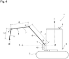
- FIG. 4 is a left side view conceptually showing a coordinate system and the turning work vehicle 1.
- the coordinate system is an orthogonal coordinate system defined by a horizontal X-axis extending from right to left in FIG. 4 , a horizontal Y-axis (see FIG. 5 ) that is perpendicular to the plane of FIG. 4 , and a vertical Z-axis extending upward and downward in FIG. 4 .
- the X-axis extends in a front-rear direction of the lower traveling body 2, and the Y-axis extends in a left-right direction (width direction) of the lower traveling body 2.
- the Z-axis corresponds with an axis, which is the center of revolution, of the revolving superstructure 3.
- the X-Y plane including an origin O is located at the height of the axis of the pivot pin 60, and the axis a of the pivot pin 40 is orthogonal to the X-Y plane.
- FIG. 5 is a plan view conceptually showing a coordinate system and the turning work vehicle 1.
- the position of the work machine 5 illustrated in FIG. 4 is indicated by a chain line in FIG. 5 .
- the axis a of the pivot pin 40 is arranged on the X-axis.
- a revolving angle ⁇ 1 (see FIG. 6 ) of the revolving superstructure 3 with respect to the lower traveling body 2 is assumed with reference to the above-described state, and the revolving angle ⁇ 1 is zero in FIGs. 4 and 5 .
- the work machine 5 is arranged on the vertical plane (X-Z plane) including the axis a of the pivot pin 40 and the Z-axis.
- the swing angle ⁇ 2 of the boom bracket 4 with respect to the revolving superstructure 3 is assumed with reference to the above state, and the swing angle ⁇ 2 is zero in FIG. 4 .
- the work machine 5 is in state of being movable on the X-Z plane, in other words, each of the boom 6, the arm 7 and the bucket 8 is in a state of being vertically rotatable (i.e., rotatable to the front and rear) on the X-Z plane.
- the angle ⁇ is a tilt angle (rotation angle) of the boom 6 with reference to the axis a of the pivot pin 40.
- the angle ⁇ is a tilt angle (rotation angle) of the arm 7 with reference to an extending direction of the boom 6 (i.e., the direction of length L1).
- the angle ⁇ is a tilt angle (rotation angle) of the bucket 8 with reference to an extending direction of the arm 7 (i.e., the direction of length L2). As described above, these angles ⁇ , ⁇ and ⁇ can be detected by the position sensors 12a to 12c which constitute the position detecting device 12.
- the length L1 is a length from the proximal end portion of the boom 6 to the distal end portion of the same, or more specifically, corresponds to a direct distance from the axis of the pivot pin 60 to the axis of the pivot pin 70.
- the length L2 is a length from the proximal end portion of the arm 7 to the distal end portion of the same, or more specifically, corresponds to a direct distance from the axis of the pivot pin 70 to the axis of the pivot pin 80.
- the length L3 is a length from the proximal end portion of the bucket 8 to a distal end portion of the same, or more specifically, corresponds to a direct distance from the axis of the pivot pin 80 to the blade edge 8E. Data regarding the lengths L1 to L3 is stored in the storage device 36a in advance.
- the turning work vehicle 1 of the present embodiment includes two GPS antennas 9 and 9. Three-dimensional positional information of the antennas 9 and 9 is received by a receiving device 19 (see FIG. 3 ).
- the antennas 9 and 9 are fixed at predetermined positions on the turning work vehicle 1.
- the antennas 9 and 9 are arranged on a horizontal plane parallel to the X-Y plane.
- a relative position of the axis, which is the center of revolution, of the revolving superstructure 3 (more specifically, the Z-axis), and eventually, a relative position of the origin O (global coordinates) with respect to the antennas 9 and 9 are previously acquired on the basis of the specifications of the turning work vehicle 1, or by measurement carried out in advance. Further, such data is stored in the storage device 36a.
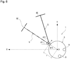
- FIG. 6 is a plan view conceptually showing the coordinate system and the turning work vehicle 1 as in FIG. 5 .
- FIG. 6 is different from FIG. 5 in that the revolving superstructure 3 is revolved.
- the position of the work machine 5 when the swing angle ⁇ 2 is zero is shown by a chain line. Since a turning radius r of the axis a can be previously acquired, the acquired data is stored in the storage device 36a.
- the revolving angle ⁇ 1 of the revolving superstructure 3 with respect to the lower traveling body 2 can be calculated on the basis of the three-dimensional positional information of the antennas 9 and 9, and the data stored in the storage device 36a, and processing therefor is performed by the arithmetic unit 36b. As long as the information necessary for calculating the revolving angle ⁇ 1 can be obtained, the location for installing the antennas 9 and 9 on the turning work vehicle 1 is not particularly limited.
- the global coordinates (Xg2, Yg2, Zg2) of the blade edge 8E can be obtained by converting the three-dimensional coordinates (Xo2, Yo2, Zo2) of the blade edge 8E by the following formula:
- the horizontal position (and eventually, the swing angle ⁇ 2) of the boom bracket 4 with respect to the revolving superstructure 3 is detected by the position detecting device 11, and the vertical position (and eventually, angles ⁇ , ⁇ and ⁇ ) of the work machine 5 with respect to the revolving superstructure 3 is detected by the position detecting device 12, thereby calculating the position of the blade edge 8E on the basis of those results of detection.
- Such arithmetic processing is executed by the arithmetic unit 36b while the data stored in the storage device 36a, and the information transmitted from the receiving device 19 are being referred to as appropriate.
- a result of the calculation can be notified to the operator by displaying the result on the display device 37, for example.
- the position of the blade edge 8E which is the construction work edge of the work machine 5
- the position of the side section 8S can be calculated by the arithmetic unit 36b.
- the mutual positional relationship between the blade edge 8E and the side section 8S is previously acquired on the basis of the specifications of the work machine 5, or by measurement carried out in advance, and such data is stored in the storage device 36a.
- FIG. 7 is a flowchart showing operation guidance given during the construction.
- FIGS. 8 to 10 each show a screen of the display device 37 that is exhibited during the construction.
- the revolving superstructure 3, the work machine 5, and the bucket 8 are indicated by icons 93, 95, and 98, respectively.
- the left side of the screen is configured as a display field C1 showing the turning work vehicle in a plan view.
- the turning work vehicle is schematically represented by the revolving superstructure 3, and the work machine 5 including the bucket 8.
- the right side of the screen is configured as a display field C2 showing the revolving superstructure 3 and the work machine 5 that are separated from each other in a plan view.
- step S1 information about the current position and a posture of the turning work vehicle 1 is acquired (step S1).
- the aforementioned information can be acquired from, for example, the three-dimensional positional information of the antenna 9 and 9, and a relative positional relationship between the antenna 9 and 9 and the axis, which is the center of revolution, of the revolving superstructure 3.
- positional information of the bucket 8, or specifically, the positional information of the blade edge 8E of the bucket 8 is obtained (step S2).
- the above information can be calculated by the arithmetic unit 36b, on the basis of the results of detection by the position detecting devices 11 and 12 installed on the turning work vehicle 1.
- the predetermined excavation area 90 where a ditch is to be excavated is set (step S3).
- the above setting is performed on the screen using the operation panel of the operating device 33, for example.
- FIG. 8 shows the state before guidance is displayed.
- the display field C1 the current position and the posture of the turning work vehicle 1 obtained in step S1, and the position of the bucket 8 obtained in step S2 are reflected.
- a wall surface W as shown in FIG. 8 should preferably be displayed. Information regarding the position and shape of the wall surface W is acquired or generated in advance, and such data is stored in the storage device 36a. Alternatively, the wall surface W may be set on the screen using the operation panel.
- the revolving superstructure 3 and the work machine 5 in the initial state in which the predetermined excavation area 90 is set are each displayed to be oriented upward on the screen.
- the predetermined excavation area 90 that has been set in step S3 is displayed.
- the side edge of the predetermined excavation area 90 is displayed by a virtual line VL extending in an extending direction (i.e., a vertical direction in FIG. 8 ) of the predetermined excavation area 90.
- the side edge refers to the one located on the outer side in a width direction of the turning work vehicle 1 of a pair of side edges defining the predetermined excavation area 90.
- the element to be displayed is not limited to the above. That is, a center line of the predetermined excavation area 90 may be displayed, or the predetermined excavation area 90 may be displayed as a belt-like area having a predetermined width.
- the display device 37 displays the positional relationship between the bucket 8 and the predetermined excavation area 90 as shown in FIG. 8 , and the positional relationship can be observed by the icon 98 and the virtual line VL in the present embodiment.
- a state hereinafter referred to as a "set state"
- the side section 8S of the bucket 8 is aligned with the virtual line VL, which is the side edge of the predetermined excavation area 90
- the work machine 5 perform an excavation operation.
- the posture of the turning work vehicle In order to shift the state from the initial state of FIG. 8 to the set state, the posture of the turning work vehicle must be changed by making full use of the revolving operation of the revolving superstructure 3 and the swing operation of the work machine 5, and a high manipulation skill is required for the operator.
- the arithmetic unit 36b calculates the necessary revolving amount of the revolving superstructure 3 and the necessary offset amount of the work machine 5 that are needed to align the side section 8S of the bucket 8 with the side edge of the predetermined excavation area 90 (step S4).
- the necessary revolving amount can be rephrased as the revolving angle of the revolving superstructure 3 that is necessary to shift to the set state.
- the necessary offset amount can be rephrased as the swing angle of the work machine 5 that is necessary to shift to the set state in the present embodiment.
- the arithmetic unit 36b obtains by computation the revolving angle of the revolving superstructure 3, and the swing angle of the work machine 5 that are suitable for digging a side ditch.
- the display device 37 displays information for informing about an operation amount of the revolving superstructure 3 according to the necessary revolving amount, and an operation amount of the work machine 5 according to the necessary offset amount (step S5).
- FIG. 9 is an example of a guidance screen displaying such information.
- icons 93s and 95s indicating the revolving superstructure 3 and the work machine 5 in the set state are displayed.
- an icon 93g of the revolving superstructure 3 for informing about the revolution that is necessary to shift to the set state, and an icon 95g of the work machine 5 for the same purpose are displayed.
- the operator is informed that the revolving superstructure 3 must be revolved to the right, and the work machine 5 must be swung to the left.
- a revolving angle ⁇ 3 which is the operation amount of the revolving superstructure 3 according to the necessary revolving amount that has been calculated, is reflected.
- a swing angle ⁇ 4 which is the operation amount of the work machine 5 according to the necessary offset amount that has been calculated, is reflected.
- the operator can visually recognize how much the revolving superstructure 3 should be revolved to the right, in view of the positional relationship between the icon 93 and the icon 93g. Also, the operator can visually recognize how much the work machine 5 should be swung to the left, in view of the positional relationship between the icon 95 and the icon 95g.
- Numerical values of the revolving angle ⁇ 3 and the swing angle ⁇ 4, and the display of arrows A3 and A4 may be omitted as appropriate.
- visual effects may be enhanced by using light, or an acoustic effect may be added by using sound.
- step S6 When the operator revolves the revolving superstructure 3 and/or swings the work machine 5, the positional information of (the blade edge 8E of) the bucket 8 according to such an operation is obtained (step S6), and whether the bucket 8 has come into contact with the virtual line VL is determined (step S7). If the bucket 8 is not in contact with the virtual line VL, the positions of the revolving superstructure 3 and the work machine 5 are displayed on the screen (in the display field C1) (step S8), and the positional information of the bucket 8 is continuously obtained. If the bucket 8 has come into contact with the virtual line VL, a further revolving operation of the revolving superstructure 3 is prohibited (step S9).
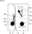
- FIG. 10 shows an example of the screen when the bucket 8 has come into contact with the virtual line VL. If the revolving superstructure 3 is revolved to the right from this state, the bucket 8 will collide with the wall surface W. Thus, clockwise turning of the revolving superstructure 3 is restricted in order to prevent the collision. For the same reason, it is also possible to restrict rightward swing operation of the work machine 5.
- the display system 50 is provided with the safety device 36c (see FIG. 3 ), which restricts revolution of the revolving superstructure 3 and an offset (a swing in the present embodiment) of the work machine 5 so that the bucket 8 does not cross over the side edge of the predetermined excavation area 90.
- the safety device 36c sends a signal to the main unit controller 34 when the bucket 8 has come into contact with the virtual line VL, and executes restriction of the revolution and offset as described above.
- the screen may be blinked or a sound effect may be produced, for example, to notify the operator of the fact that the bucket 8 is in contact with the virtual line VL.
- the display device 37 When the bucket 8 is in contact with the virtual line VL, the display device 37 displays that the revolution of the revolving superstructure 3 is restricted, and information for informing about the swing angle of the work machine 5 that is necessary to shift to the set state, as shown in FIG. 10 (step S10).
- the display system 50 provides the operator with information useful for construction of digging of a side ditch, such as in which direction and how much the revolving superstructure 3 should be revolved, and in which direction and how much the work machine 5 should be swung.
- the display device 37 displays the revolving superstructure 3, and the work machine 5 extending from the front end portion of the revolving superstructure 3.
- the display is not limited to the above, and the other screen layout can alternatively be adopted.
- the display device 37 should display at least the bucket 8 and the predetermined excavation area 90 in a plan view.
- the plan view may be a view seen from above along the axial direction of central axis of revolution of the revolving superstructure 3.
- the display of the predetermined excavation area 90 may be indicated by only the side edge.
- the offset of the work machine is performed by swinging the work machine to right and left with respect to the revolving superstructure.
- the offset is not limited to the aforementioned example. That is, the offset may be performed by translating (the arm or the boom of) the work machine to the right and left with respect to the revolving superstructure.
- Such a turning work vehicle is disclosed in, for example, Japanese Unexamined Patent Application No. Hei 8-326086 A or Japanese Unexamined Patent Application No. 2011-184965 A , the applications of which were filed by the present applicant.
- the position of the bucket, and the necessary offset amount of the work machine may be calculated, on the basis of an actuation amount of an actuator (for example, the expansion/contraction amount of the cylinder) which translates the work machine to the right and left, instead of the swing angle of the work machine described above (i.e., the swing angle of the boom bracket).
- an actuator for example, the expansion/contraction amount of the cylinder
- a three-dimensional position of a blade edge of the bucket is described.
- the calculation is not limited to the above, and a two-dimensional position may be obtained by calculation.
- the position of the blade edge of the bucket when the predetermined excavation area is set may be assumed as a work start point, and the necessary revolving amount and the necessary offset amount as described above may be calculated in consideration of the mutual positional relationship between the position of the blade edge and the predetermined excavation area.
- the GPS antennas can be omitted.
- a configuration may be made to detect a revolving angle of the revolving superstructure with respect to the lower traveling body by a position sensor (for example, an angle sensor) installed on the revolving superstructure.
Landscapes
- Engineering & Computer Science (AREA)
- Mining & Mineral Resources (AREA)
- Civil Engineering (AREA)
- General Engineering & Computer Science (AREA)
- Structural Engineering (AREA)
- Mechanical Engineering (AREA)
- Aviation & Aerospace Engineering (AREA)
- Radar, Positioning & Navigation (AREA)
- Remote Sensing (AREA)
- Physics & Mathematics (AREA)
- General Physics & Mathematics (AREA)
- Automation & Control Theory (AREA)
- Component Parts Of Construction Machinery (AREA)
- Operation Control Of Excavators (AREA)
Abstract
Description
- The present invention relates to a display system of a turning work vehicle, a turning work vehicle, and a display method for a turning work vehicle.
- In a turning work vehicle such as a backhoe, by detecting a position of a construction work edge of a work machine, highly accurate control is possible. Being able to do so helps to achieve automation of the work and securing safety of the surroundings.
Patent Literature 1 to 3 describes a hydraulic shovel as the turning work vehicle provided with means for detecting a position of the construction work edge of the work machine that has a bucket (that is, a blade edge of the bucket). - In addition, in a compact excavator, in particular, in order to enhance the workability in a narrow space, a function which enables the work machine to be offset relative to a revolving superstructure in a horizontal direction may be provided. In one aspect, the offset of the work machine is realized by swinging the work machine to right and left with respect to the revolving superstructure, and in another aspect, the offset is realized by translating the work machine to the right and left with respect to the revolving superstructure.
-
Patent Literature 1 describes a technique for detecting a position of a construction work edge, on the basis of outputs from a plurality of position sensors installed on a work machine, and positional information from two GPS antennas installed on a construction machine body. However, when this technique is applied to a turning work vehicle which is capable of offsetting a work machine in the horizontal direction as described above, since a relative relation between the output from the position sensor and the positional information from the antenna varies depending on the offset of the work machine, it is not possible to detect the position of the construction work edge. -
Patent Literature 2 describes a technique for detecting a turning central position of an arm, on the basis of positional information from a GPS antenna installed on a construction work edge of the arm, and positional information from a GPS antenna installed on a construction machine body, and further detecting a position of the construction work edge on the basis of outputs from a plurality of position sensors. However, since the antenna needs to be installed at the construction work edge where great vibration and impact are to be applied during the work, the technique is not convenient in performing position detection of the construction work edge at high accuracy. -
Patent Literature 3 describes a technique for displaying, on a screen, targeted turning information obtained for a blade edge of a bucket to face a targeted surface. However, when this technique is applied to a turning work vehicle which is capable of offsetting the work machine in the horizontal direction as described above, it is not possible to reflect the positional information of the bucket that has been changed by the offset. In addition, in construction such as digging of a side ditch, while a side section of the bucket needs to be aligned with a side edge of an excavation scheduled area, the technique in question does not consider the offset of the work machine, and the side section of the bucket. Thus, a high skill is required for an operator. -
- Patent Literature 1: Japanese Unexamined Patent Application No.
2002-181538 A - Patent Literature 2: Japanese Unexamined Patent Application No.
2002-181539 A - Patent Literature 3: PCT International Publication No.
WO 2015/173936 - The present invention has been conceived in view of the above circumstances, and an object of the present invention is to provide a display system of a turning work vehicle, in which the turning work vehicle is capable of offsetting a work machine in a horizontal direction, and the display system is useful for operational assistance for construction such as digging of a side ditch, a turning work vehicle, and a display method for a turning work vehicle.
- A display system of a turning work vehicle according to the present invention is used for the turning work vehicle which can offset a work machine including a bucket relative to a revolving superstructure in a horizontal direction, in which the display system includes: an arithmetic unit, which calculates a position of the bucket on the basis of a result of detection by a position detecting device installed on the turning work vehicle, and calculates a necessary revolving amount of the revolving superstructure and a necessary offset amount of the work machine that are needed to align a side section of the bucket with a side edge of a predetermined excavation area; and a display device which displays a positional relationship between the bucket and the predetermined excavation area. Such a configuration contributes to, in the turning work vehicle capable of offsetting the work machine in the horizontal direction, operational assistance for construction such as digging of a side ditch.
- The display device should preferably display information for informing about an operation amount of the revolving superstructure according to the necessary revolving amount, and an operation amount of the work machine according to the necessary offset amount. By this feature, it is possible to give operation guidance to the operator regarding revolution of the revolving superstructure and the offset of the work machine for aligning the side section of the bucket with the side edge of the predetermined excavation area.
- It is preferable that a safety device, which restricts the revolution of the revolving superstructure and the offset of the work machine so that the bucket does not cross over the side edge of the predetermined excavation area, should be provided. By this feature, it is possible to prevent the bucket from colliding with a wall surface when wall-side excavation is to be performed.
- The offset of the work machine may be performed by swinging the work machine to right and left with respect to the revolving superstructure.
- The display device should preferably display at least the bucket and the predetermined excavation area in a plan view. By this feature, it is possible to accurately convey to the operator the positional relationship between the bucket and the predetermined excavation area, which is useful in aligning the side section of the bucket with the side edge of the predetermined excavation area.
- The display device should preferably display the side edge of the predetermined excavation area by a virtual line extending in an extending direction of the predetermined excavation area. By displaying a position of the side edge of the predetermined excavation area, it is possible to effectively assist the operation of the operator.
- A turning work vehicle according to the present invention includes: the display system of the turning work vehicle as described above; a lower traveling body; the revolving superstructure which is provided above the lower traveling body so as to be revolvable; and the work machine which can be offset relative to the revolving superstructure in the horizontal direction. As the above-described display system is provided, such a turning work vehicle contributes to operational assistance for construction such as digging of a side ditch.
- A display method for a turning work vehicle according to the present invention is used for the turning work vehicle which can offset a work machine including a bucket relative to a revolving superstructure in a horizontal direction, in which the display method includes: calculating a position of the bucket on the basis of a result of detection by a position detecting device installed on the turning work vehicle, and calculating a necessary revolving amount of the revolving superstructure and a necessary offset amount of the work machine that are needed to align a side section of the bucket with a side edge of a predetermined excavation area; and displaying a positional relationship between the bucket and the predetermined excavation area on a screen of a display device. Such a method contributes to, in the turning work vehicle capable of offsetting the work machine in the horizontal direction, operational assistance for construction such as digging of a side ditch.
-
-
FIG. 1 is a perspective view showing an example of a turning work vehicle according to the present invention. -
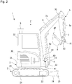
FIG. 2 is a right side view of the turning work vehicle ofFIG. 1 . -
FIG. 3 is a block diagram showing a control system provided in the turning work vehicle. -
FIG. 4 is a left side view conceptually showing a coordinate system and the turning work vehicle. -
FIG. 5 is a plan view conceptually showing a coordinate system and the turning work vehicle. -
FIG. 6 is a plan view conceptually showing the coordinate system and the turning work vehicle. -
FIG. 7 is a flowchart showing an example of operation guidance given during construction. -
FIG. 8 is a diagram illustrating an example of a screen of a display device that is exhibited during construction of digging a side ditch. -
FIG. 9 is a diagram showing an example of a screen of the display device that is exhibited during the construction of digging a side ditch. -
FIG. 10 is a diagram illustrating an example of a screen of the display device that is exhibited during the construction of digging a side ditch. - Hereinafter, an embodiment of the present invention will be described with reference to the accompanying drawings.
- As shown in
FIGs. 1 and2 , aturning work vehicle 1 is provided with: a lower travelingbody 2; a revolvingsuperstructure 3 which is provided above the lower travelingbody 2 so as to be revolvable; and awork machine 5 which can be offset relative to the revolvingsuperstructure 3 in a horizontal direction. In the present embodiment, theturning work vehicle 1 is configured as a shovel provided with a boom swing function (i.e., a backhoe), and the offset of thework machine 5 is performed by swinging thework machine 5 to right and left with respect to the revolvingsuperstructure 3. In general, the boom swing function is provided in a compact excavator of which workability in a narrow space is required. - The lower traveling
body 2 is driven as it receives power from anengine 30, and causes the turningwork vehicle 1 to travel and turn. Thelower traveling body 2 is provided with a pair of left andright crawlers right traveling motors aforementioned crawlers crawlers base 23 revolvably supporting the revolvingsuperstructure 3 is provided. Also, the lower travelingbody 2 is provided with: a pair ofblade arms blade 25, which serves as an earth-moving plate, extending in a left-right direction between distal end portions of theblade arms blade cylinder 26 for rotating theblade 25 up and down. - The revolving
superstructure 3 is configured to be able to perform a revolving operation about an axis extending in a vertical direction at a central portion thereof.FIGs. 1 and2 illustrate a Z-axis which corresponds with the aforementioned axis. The revolvingsuperstructure 3 is formed in a substantially disk shape in a plan view to be revolvable within a breadth of the lower traveling body 2 (i.e., a distance between an outer edge of theleft crawler 21 and an outer edge of the right crawler 21). The revolvingsuperstructure 3 is equipped with theengine 30, acounterweight 31, acabin 32, etc. A driving part surrounded by thecabin 32 is provided with, for example, a driver's seat (not shown) where an operator is seated, an operating device 33 (seeFIG. 3 ) for the operator to perform an operation, and a display device 37 (seeFIG. 3 ) which display various kinds of information. - The turning
work vehicle 1 is provided with aboom bracket 4, which is a swing body supported on the revolvingsuperstructure 3 so as to be horizontally rotatable. Theboom bracket 4 is mounted on a front end portion of the revolvingsuperstructure 3 via astay 33. Thestay 33 is provided with apivot pin 40 in which an axis a (seeFIG. 4 ) is oriented in the vertical direction. Theboom bracket 4 is supported so as to be horizontally rotatable (that is, swingable right and left) about thepivot pin 40 of theboom bracket 4. Theboom bracket 4 is rotated on a horizontal plane (for example, an X-Y plane shown inFIG. 5 ) orthogonal to the axis a. Aswing cylinder 41, which expands and contracts in a front-rear direction, is provided between the revolvingsuperstructure 3 and theboom bracket 4. The horizontal rotation of theboom bracket 4 is performed in accordance with the expansion and contraction of theswing cylinder 41. - The
work machine 5 is driven as it receives power from theengine 30, and performs excavation work of the land, for example, in accordance with an operation performed in the driving part. Thework machine 5 is supported on theboom bracket 4 so as to be vertically rotatable. Theboom bracket 4 is provided with apivot pin 60 in which an axis is oriented in the horizontal direction. A proximal end portion of the work machine 5 (i.e., a proximal end portion of aboom 6 which will be described later) is supported so as to be vertically rotatable about the above-mentionedpivot pin 60. Thework machine 5 is rotated on a vertical plane (for example, an X-Z plane shown inFIG. 4 ) orthogonal to the axis of thepivot pin 60. Thework machine 5 moves horizontally relative to the revolving superstructure 3 (i.e., is offset in the horizontal direction) by performing a swing operation in tandem with the horizontal rotation of theboom bracket 4. - The
work machine 5 includes theboom 6, anarm 7, and abucket 8, which is an attachment for excavation. Theboom 6 is mounted on theboom bracket 4 so as to be vertically rotatable. Theboom 6 extends in the vertical direction from the proximal end portion supported on theboom bracket 4, and is bent in the shape of a boomerang in a side view. Aboom cylinder 6a, which is movable in an expandable and contractible manner, is provided between theboom bracket 4 and a middle portion of theboom 6. The vertical rotation of theboom 6 with respect to theboom bracket 4 is performed in accordance with the expansion and contraction of theboom cylinder 6a. - The
arm 7 is attached to theboom 6 so as to be vertically rotatable. At a distal end portion of theboom 6, apivot pin 70 in which an axis is oriented in the horizontal direction is provided. A proximal end portion of thearm 7 is supported so as to be vertically rotatable (i.e., rotatable to the front and rear) about the above-mentionedpivot pin 70. Anarm cylinder 7a, which is movable in an expandable and contractible manner, is provided between the middle portion of theboom 6 and the proximal end portion of thearm 7. The vertical rotation of thearm 7 with respect to theboom 6 is performed in accordance with the expansion and contraction of thearm cylinder 7a. - The
bucket 8 is attached to thearm 7 so as to be vertically rotatable. At a distal end portion of thearm 7, apivot pin 80 in which an axis is oriented in the horizontal direction is provided. A proximal end portion of thebucket 8 is supported so as to be vertically rotatable (i.e., rotatable to the front and rear) about the above-mentionedpivot pin 80. Abucket link 81 is interposed between the distal end portion of thearm 7 and thebucket 8. Thebucket link 81 is configured as a link which transmits a driving force to thebucket 8. Abucket cylinder 8a, which is movable in an expandable and contractible manner, is provided between thebucket link 81 and the proximal end portion of thearm 7. The vertical rotation of thebucket 8 with respect to thearm 7 is performed in accordance with the expansion and contraction of thebucket cylinder 8a. Thebucket 8 includes ablade edge 8E, which serves as a construction work edge, and aside section 8S formed by a side panel. - An example of a control system provided in the turning
work vehicle 1 will be briefly described. As shown inFIG. 3 , the turningwork vehicle 1 is provided with: the operatingdevice 33; amain unit controller 34, which is a vehicle control device; a workmachine control device 35; adisplay controller 36, which is a display control device; and adisplay device 37. The operatingdevice 33 includes a lever, a switch, a pedal, an operation panel, etc. The operation panel may also serve as thedisplay device 37. Themain unit controller 34 controls a traveling operation of thelower traveling body 2 and a revolving operation of the revolvingsuperstructure 3, on the basis of a control signal from the operatingdevice 33. Also, themain unit controller 34 controls the workmachine control device 35 and thedisplay controller 36, on the basis of the control signal from the operatingdevice 33. - The work
machine control device 35 controls the operation of thework machine 5. The operation includes not only the vertical rotation of each of theboom 6, thearm 7, and thebucket 8, but also the swing operation (offset) of thework machine 5 caused by the horizontal rotation of theboom bracket 4. Thedisplay controller 36 is provided with astorage device 36a, anarithmetic unit 36b, and asafety device 36c. Thestorage device 36a is configured from random access memory (RAM) and read-only memory (ROM), etc., and stores various kinds of data which will be described later. Thearithmetic unit 36b executes predetermined arithmetic processing, on the basis of the data stored in thestorage device 36a, and a detection signal or the like fromposition detecting devices display controller 36 can display a result of the arithmetic processing, etc., on a screen of thedisplay device 37. - A
display system 50 is used for the turningwork vehicle 1 capable of offsetting thework machine 5 having thebucket 8 relative to the revolvingsuperstructure 1 in the horizontal direction, and provides the operator with information useful for operational assistance for construction in excavation work such as digging of a side ditch. Thedisplay system 50 is provided with thearithmetic unit 36b and thedisplay device 37 as described above. Thearithmetic unit 36b calculates the position of thebucket 8 on the basis of results of detection by theposition detecting devices work vehicle 1, and calculates a necessary revolving amount of the revolvingsuperstructure 3 and a necessary offset amount of thework machine 5 that are needed to align theside section 8S of thebucket 8 with a side edge of a predetermined excavation area 90 (seeFIG. 8 ). Thedisplay device 37 displays a positional relationship between thebucket 8 and thepredetermined excavation area 90. - Next, a method for detecting a position of the
bucket 8 will be described. Strictly speaking, a position of theblade edge 8E of thebucket 8 is detected, and a position of theside section 8S is calculated on the basis of the blade edge position. As illustrated inFIG. 3 , the turningwork vehicle 1 is provided with the position detecting device 11 (a first position detecting device), and the position detecting device 12 (a second position detecting device). Theposition detecting device 11 detects a horizontal position of theboom bracket 4 with respect to the revolvingsuperstructure 3. Theposition detecting device 12 detects a vertical position of thework machine 5 with respect to the revolvingsuperstructure 3. Thearithmetic unit 36b calculates the position of theblade edge 8E on the basis of the results of detection by theposition detecting devices - In the present embodiment, the
position detecting device 11 is constituted by a position sensor installed on theboom bracket 4 as shown inFIG. 2 . The position sensor detects movement of theboom bracket 4 on a plane where theboom bracket 4 is movable, or more specifically, the movement on a horizontal plane that is perpendicular to the axis a of thepivot pin 40. By installing such a position sensor on theboom bracket 4, it is possible to detect the horizontal position of theboom bracket 4 with respect to the revolvingsuperstructure 3 comparatively easily. The present embodiment represents an example in which an acceleration sensor is used as the position sensor which constitutes theposition detecting device 11 to detect a swing angle θ2 of theboom bracket 4 with respect to the revolvingsuperstructure 3. - The position sensor which constitutes the
position detecting device 11 can alternatively be installed on theswing cylinder 41. Also, as the position sensor, although an inertial sensor such as the acceleration sensor can be used as described above, the position sensor is not limited to this example. For example, a gyro sensor, an angle sensor (tilt sensor), or a cylinder sensor (stroke sensor) can be used instead. When a cylinder sensor is used, the swing angle θ2 can be detected on the basis of an expansion/contraction amount (stroke amount) of theswing cylinder 41, whereby the horizontal position of theboom bracket 4 with respect to the revolvingsuperstructure 3 can be detected. - In the present embodiment, the
position detecting device 12 includes aposition sensor 12a installed on theboom 6, aposition sensor 12b installed on thearm 7, and aposition sensor 12c installed on thebucket link 81, as shown inFIG. 1 . Each of theposition sensors 12a to 12c detects movement of thework machine 5 on a plane where thework machine 5 is movable, or more specifically, the movement on a vertical plane including the axis a of thepivot pin 40. The present embodiment represents an example in which acceleration sensors are used as theposition sensors 12a to 12c to detect angles α, β and γ, which will be described later. Likewise theposition detecting device 11, the position sensors which constitute theposition detecting device 12 are not limited to inertial sensors such as the acceleration sensors. -
FIG. 4 is a left side view conceptually showing a coordinate system and the turningwork vehicle 1. The coordinate system is an orthogonal coordinate system defined by a horizontal X-axis extending from right to left inFIG. 4 , a horizontal Y-axis (seeFIG. 5 ) that is perpendicular to the plane ofFIG. 4 , and a vertical Z-axis extending upward and downward inFIG. 4 . The X-axis extends in a front-rear direction of thelower traveling body 2, and the Y-axis extends in a left-right direction (width direction) of thelower traveling body 2. The Z-axis corresponds with an axis, which is the center of revolution, of the revolvingsuperstructure 3. The X-Y plane including an origin O is located at the height of the axis of thepivot pin 60, and the axis a of thepivot pin 40 is orthogonal to the X-Y plane. -
FIG. 5 is a plan view conceptually showing a coordinate system and the turningwork vehicle 1. The position of thework machine 5 illustrated inFIG. 4 is indicated by a chain line inFIG. 5 . InFIGs. 4 and5 , the axis a of thepivot pin 40 is arranged on the X-axis. A revolving angle θ1 (seeFIG. 6 ) of the revolvingsuperstructure 3 with respect to thelower traveling body 2 is assumed with reference to the above-described state, and the revolving angle θ1 is zero inFIGs. 4 and5 . Further, inFIG. 4 , thework machine 5 is arranged on the vertical plane (X-Z plane) including the axis a of thepivot pin 40 and the Z-axis. The swing angle θ2 of theboom bracket 4 with respect to the revolvingsuperstructure 3 is assumed with reference to the above state, and the swing angle θ2 is zero inFIG. 4 . - In
FIG. 4 , thework machine 5 is in state of being movable on the X-Z plane, in other words, each of theboom 6, thearm 7 and thebucket 8 is in a state of being vertically rotatable (i.e., rotatable to the front and rear) on the X-Z plane. The angle α is a tilt angle (rotation angle) of theboom 6 with reference to the axis a of thepivot pin 40. The angle β is a tilt angle (rotation angle) of thearm 7 with reference to an extending direction of the boom 6 (i.e., the direction of length L1). The angle γ is a tilt angle (rotation angle) of thebucket 8 with reference to an extending direction of the arm 7 (i.e., the direction of length L2). As described above, these angles α, β and γ can be detected by theposition sensors 12a to 12c which constitute theposition detecting device 12. - The length L1 is a length from the proximal end portion of the
boom 6 to the distal end portion of the same, or more specifically, corresponds to a direct distance from the axis of thepivot pin 60 to the axis of thepivot pin 70. The length L2 is a length from the proximal end portion of thearm 7 to the distal end portion of the same, or more specifically, corresponds to a direct distance from the axis of thepivot pin 70 to the axis of thepivot pin 80. The length L3 is a length from the proximal end portion of thebucket 8 to a distal end portion of the same, or more specifically, corresponds to a direct distance from the axis of thepivot pin 80 to theblade edge 8E. Data regarding the lengths L1 to L3 is stored in thestorage device 36a in advance. - The turning
work vehicle 1 of the present embodiment includes twoGPS antennas antennas FIG. 3 ). Theantennas work vehicle 1. In the present embodiment, theantennas antennas work vehicle 1, or by measurement carried out in advance. Further, such data is stored in thestorage device 36a. -
FIG. 6 is a plan view conceptually showing the coordinate system and the turningwork vehicle 1 as inFIG. 5 . However,FIG. 6 is different fromFIG. 5 in that the revolvingsuperstructure 3 is revolved. InFIG. 6 , the position of thework machine 5 when the swing angle θ2 is zero is shown by a chain line. Since a turning radius r of the axis a can be previously acquired, the acquired data is stored in thestorage device 36a. The revolving angle θ1 of the revolvingsuperstructure 3 with respect to thelower traveling body 2 can be calculated on the basis of the three-dimensional positional information of theantennas storage device 36a, and processing therefor is performed by thearithmetic unit 36b. As long as the information necessary for calculating the revolving angle θ1 can be obtained, the location for installing theantennas work vehicle 1 is not particularly limited. - First, in a state where the revolving
superstructure 3 is not revolved and thework machine 5 is not swung (that is, when θ1 = 0 and θ2 = 0), as shown inFIG. 4 and by the chain line inFIG. 5 , given that the three-dimensional coordinates of theblade edge 8E where the position of the axis a on the X-Y plane is a base point are (Xa, Ya, Za), the coordinates (Xa, Ya, Za) can be obtained by the following formula:


- Next, in a state where the
work machine 5 is swung without revolving the revolving superstructure 3 (i.e., when θ1 = 0 and θ2 ≠ 0), as shown by a solid line inFIG. 5 , given that the three-dimensional coordinates of theblade edge 8E where the position of the axis a on the X-Y plane is the base point are (Xa1, Ya1, Za1), the coordinates (Xa1, Ya1, Za1) can be obtained by the following formula:


- Further, in the state where the revolving
superstructure 3 is revolved (θ1 ≠ 0), as shown inFIG. 6 , given that the three-dimensional coordinates of the axis a where the origin O on the X-Y plane is the starting point are (Xo0, Yo0, Zo0), and that the turning radius of the axis a is r, the coordinates (Xo0, Yo0, Zo0) can be obtained by the following formula:


- Furthermore, in a state where the revolving
superstructure 3 is revolved, and thework machine 5 is not swung (i.e., when θ1 ≠ 0 and θ2 = 0), as shown by the chain line inFIG. 6 , given that the three-dimensional coordinates of theblade edge 8E where the origin O on the X-Y plane is the starting point are (Xo1, Yo1, Zo1), the coordinates (Xo1, Yo1, Zo1) can be obtained by the following formula:


- Moreover, in a state where the revolving
superstructure 3 is revolved, and thework machine 5 is swung (i.e., when θ1 ≠ 0 and θ2 ≠ 0), as shown by a solid line inFIG. 6 , given that the three-dimensional coordinates of theblade edge 8E where the origin O on the X-Y plane is the starting point are (Xo2, Yo2, Zo2), the coordinates (Xo2, Yo2, Zo2) can be obtained by the following formula:


- Therefore, given that the global coordinates of the origin O are (A, B, C), the global coordinates (Xg2, Yg2, Zg2) of the
blade edge 8E can be obtained by converting the three-dimensional coordinates (Xo2, Yo2, Zo2) of theblade edge 8E by the following formula:


- As described above, in the present embodiment, the horizontal position (and eventually, the swing angle θ2) of the
boom bracket 4 with respect to the revolvingsuperstructure 3 is detected by theposition detecting device 11, and the vertical position (and eventually, angles α, β and γ) of thework machine 5 with respect to the revolvingsuperstructure 3 is detected by theposition detecting device 12, thereby calculating the position of theblade edge 8E on the basis of those results of detection. Such arithmetic processing is executed by thearithmetic unit 36b while the data stored in thestorage device 36a, and the information transmitted from the receivingdevice 19 are being referred to as appropriate. A result of the calculation can be notified to the operator by displaying the result on thedisplay device 37, for example. - As described above, according to the present embodiment, in the turning
work vehicle 1 having the boom swing function, the position of theblade edge 8E, which is the construction work edge of thework machine 5, can be detected with high accuracy. Further, based on the detected position of theblade edge 8E, and a mutual positional relationship between theblade edge 8E and the side section8S, the position of theside section 8S can be calculated by thearithmetic unit 36b. The mutual positional relationship between theblade edge 8E and theside section 8S is previously acquired on the basis of the specifications of thework machine 5, or by measurement carried out in advance, and such data is stored in thestorage device 36a. - Next, operation guidance given during construction of digging of a side ditch will be described.
FIG. 7 is a flowchart showing operation guidance given during the construction.FIGS. 8 to 10 each show a screen of thedisplay device 37 that is exhibited during the construction. On the screen, the revolvingsuperstructure 3, thework machine 5, and thebucket 8 are indicated byicons superstructure 3, and thework machine 5 including thebucket 8. The right side of the screen is configured as a display field C2 showing the revolvingsuperstructure 3 and thework machine 5 that are separated from each other in a plan view. - First, information about the current position and a posture of the turning
work vehicle 1 is acquired (step S1). The aforementioned information can be acquired from, for example, the three-dimensional positional information of theantenna antenna superstructure 3. Next, positional information of thebucket 8, or specifically, the positional information of theblade edge 8E of thebucket 8 is obtained (step S2). As described previously, the above information can be calculated by thearithmetic unit 36b, on the basis of the results of detection by theposition detecting devices work vehicle 1. Then, thepredetermined excavation area 90 where a ditch is to be excavated is set (step S3). The above setting is performed on the screen using the operation panel of the operatingdevice 33, for example. -
FIG. 8 shows the state before guidance is displayed. In the display field C1, the current position and the posture of the turningwork vehicle 1 obtained in step S1, and the position of thebucket 8 obtained in step S2 are reflected. When wall-side excavation is to be performed, a wall surface W as shown inFIG. 8 should preferably be displayed. Information regarding the position and shape of the wall surface W is acquired or generated in advance, and such data is stored in thestorage device 36a. Alternatively, the wall surface W may be set on the screen using the operation panel. In the display field C2, the revolvingsuperstructure 3 and thework machine 5 in the initial state in which the predeterminedexcavation area 90 is set are each displayed to be oriented upward on the screen. - In the display field C1, the
predetermined excavation area 90 that has been set in step S3 is displayed. In the present embodiment, the side edge of thepredetermined excavation area 90 is displayed by a virtual line VL extending in an extending direction (i.e., a vertical direction inFIG. 8 ) of thepredetermined excavation area 90. The side edge refers to the one located on the outer side in a width direction of the turningwork vehicle 1 of a pair of side edges defining thepredetermined excavation area 90. By displaying the side edge of thepredetermined excavation area 90 in this way, it is possible to effectively assist the operation of the operator. However, the element to be displayed is not limited to the above. That is, a center line of thepredetermined excavation area 90 may be displayed, or thepredetermined excavation area 90 may be displayed as a belt-like area having a predetermined width. - The
display device 37 displays the positional relationship between thebucket 8 and thepredetermined excavation area 90 as shown inFIG. 8 , and the positional relationship can be observed by theicon 98 and the virtual line VL in the present embodiment. In order to excavate a ditch in thepredetermined excavation area 90, having ensured a state (hereinafter referred to as a "set state") in which theside section 8S of thebucket 8 is aligned with the virtual line VL, which is the side edge of thepredetermined excavation area 90, it is necessary to make thework machine 5 perform an excavation operation. In order to shift the state from the initial state ofFIG. 8 to the set state, the posture of the turning work vehicle must be changed by making full use of the revolving operation of the revolvingsuperstructure 3 and the swing operation of thework machine 5, and a high manipulation skill is required for the operator. - Therefore, in the
display system 50, in order to serve for operational assistance for construction, thearithmetic unit 36b calculates the necessary revolving amount of the revolvingsuperstructure 3 and the necessary offset amount of thework machine 5 that are needed to align theside section 8S of thebucket 8 with the side edge of the predetermined excavation area 90 (step S4). The necessary revolving amount can be rephrased as the revolving angle of the revolvingsuperstructure 3 that is necessary to shift to the set state. Also, the necessary offset amount can be rephrased as the swing angle of thework machine 5 that is necessary to shift to the set state in the present embodiment. As described above, thearithmetic unit 36b obtains by computation the revolving angle of the revolvingsuperstructure 3, and the swing angle of thework machine 5 that are suitable for digging a side ditch. - The
display device 37 displays information for informing about an operation amount of the revolvingsuperstructure 3 according to the necessary revolving amount, and an operation amount of thework machine 5 according to the necessary offset amount (step S5).FIG. 9 is an example of a guidance screen displaying such information. In the display field C1,icons superstructure 3 and thework machine 5 in the set state are displayed. In the display field C2, anicon 93g of the revolvingsuperstructure 3 for informing about the revolution that is necessary to shift to the set state, and anicon 95g of thework machine 5 for the same purpose are displayed. In this example, the operator is informed that the revolvingsuperstructure 3 must be revolved to the right, and thework machine 5 must be swung to the left. - In the
icon 93g in the display field C2 shown inFIG. 9 , a revolving angle θ3, which is the operation amount of the revolvingsuperstructure 3 according to the necessary revolving amount that has been calculated, is reflected. Similarly, in theicon 95g, a swing angle θ4, which is the operation amount of thework machine 5 according to the necessary offset amount that has been calculated, is reflected. The operator can visually recognize how much the revolvingsuperstructure 3 should be revolved to the right, in view of the positional relationship between theicon 93 and theicon 93g. Also, the operator can visually recognize how much thework machine 5 should be swung to the left, in view of the positional relationship between theicon 95 and theicon 95g. Numerical values of the revolving angle θ3 and the swing angle θ4, and the display of arrows A3 and A4 may be omitted as appropriate. In addition, visual effects may be enhanced by using light, or an acoustic effect may be added by using sound. - When the operator revolves the revolving
superstructure 3 and/or swings thework machine 5, the positional information of (theblade edge 8E of) thebucket 8 according to such an operation is obtained (step S6), and whether thebucket 8 has come into contact with the virtual line VL is determined (step S7). If thebucket 8 is not in contact with the virtual line VL, the positions of the revolvingsuperstructure 3 and thework machine 5 are displayed on the screen (in the display field C1) (step S8), and the positional information of thebucket 8 is continuously obtained. If thebucket 8 has come into contact with the virtual line VL, a further revolving operation of the revolvingsuperstructure 3 is prohibited (step S9). -
FIG. 10 shows an example of the screen when thebucket 8 has come into contact with the virtual line VL. If the revolvingsuperstructure 3 is revolved to the right from this state, thebucket 8 will collide with the wall surface W. Thus, clockwise turning of the revolvingsuperstructure 3 is restricted in order to prevent the collision. For the same reason, it is also possible to restrict rightward swing operation of thework machine 5. Thedisplay system 50 is provided with thesafety device 36c (seeFIG. 3 ), which restricts revolution of the revolvingsuperstructure 3 and an offset (a swing in the present embodiment) of thework machine 5 so that thebucket 8 does not cross over the side edge of thepredetermined excavation area 90. Thesafety device 36c sends a signal to themain unit controller 34 when thebucket 8 has come into contact with the virtual line VL, and executes restriction of the revolution and offset as described above. In addition to prohibition of the revolving operation, the screen may be blinked or a sound effect may be produced, for example, to notify the operator of the fact that thebucket 8 is in contact with the virtual line VL. - When the
bucket 8 is in contact with the virtual line VL, thedisplay device 37 displays that the revolution of the revolvingsuperstructure 3 is restricted, and information for informing about the swing angle of thework machine 5 that is necessary to shift to the set state, as shown inFIG. 10 (step S10). By operating the revolvingsuperstructure 3 and thework machine 5 in accordance with such instructions on the screen, it is possible to achieve the set state in which theside section 8S of thebucket 8 is aligned with the virtual line VL without making thebucket 8 collide with the wall surface W. As described above, thedisplay system 50 provides the operator with information useful for construction of digging of a side ditch, such as in which direction and how much the revolvingsuperstructure 3 should be revolved, and in which direction and how much thework machine 5 should be swung. - In the present embodiment, the
display device 37 displays the revolvingsuperstructure 3, and thework machine 5 extending from the front end portion of the revolvingsuperstructure 3. However, the display is not limited to the above, and the other screen layout can alternatively be adopted. However, it is preferable that thedisplay device 37 should display at least thebucket 8 and thepredetermined excavation area 90 in a plan view. The plan view may be a view seen from above along the axial direction of central axis of revolution of the revolvingsuperstructure 3. Also, the display of thepredetermined excavation area 90 may be indicated by only the side edge. - In the present embodiment, an example in which the offset of the work machine is performed by swinging the work machine to right and left with respect to the revolving superstructure is described. However, the offset is not limited to the aforementioned example. That is, the offset may be performed by translating (the arm or the boom of) the work machine to the right and left with respect to the revolving superstructure. Such a turning work vehicle is disclosed in, for example, Japanese Unexamined Patent Application No.
Hei 8-326086 A 2011-184965 A - In the present embodiment, an example of calculating a three-dimensional position of a blade edge of the bucket is described. However, the calculation is not limited to the above, and a two-dimensional position may be obtained by calculation. For example, the position of the blade edge of the bucket when the predetermined excavation area is set may be assumed as a work start point, and the necessary revolving amount and the necessary offset amount as described above may be calculated in consideration of the mutual positional relationship between the position of the blade edge and the predetermined excavation area. In that case, since the global coordinates do not need to be used, the GPS antennas can be omitted. In that event, a configuration may be made to detect a revolving angle of the revolving superstructure with respect to the lower traveling body by a position sensor (for example, an angle sensor) installed on the revolving superstructure.
- The present invention is in no way limited to the embodiment described above, and various improvements and modifications can be made within the scope not departing from the spirit of the present invention.
-
- 1 Turning work vehicle
- 2 Lower traveling body
- 3 Revolving superstructure
- 4 Boom bracket
- 5 Work machine
- 6 Boom
- 7 Arm
- 8 Bucket
- 8a Bucket cylinder
- 8E Blade edge
- 8S Side section
- 11 Position detecting device
- 12 Position detecting device
- 36 Display controller
- 36a Storage device
- 36b Arithmetic unit
- 36c Safety device
- 37 Display device
- 50 Display system
- 90 Predetermined excavation area
Claims (8)
- A display system of a turning work vehicle, the display system being used for the turning work vehicle which can offset a work machine including a bucket relative to a revolving superstructure in a horizontal direction, the display system comprising:an arithmetic unit, which calculates a position of the bucket based on a result of detection by a position detecting device installed on the turning work vehicle, and calculates a necessary revolving amount of the revolving superstructure and a necessary offset amount of the work machine that are needed to align a side section of the bucket with a side edge of a predetermined excavation area; anda display device which displays a positional relationship between the bucket and the predetermined excavation area.
- The display system of the turning work vehicle according to claim 1, wherein the display device displays information for informing about an operation amount of the revolving superstructure according to the necessary revolving amount, and an operation amount of the work machine according to the necessary offset amount.
- The display system of the turning work vehicle according to claim 1 or 2, further comprising a safety device which restricts the revolution of the revolving superstructure and the offset of the work machine so that the bucket does not cross over the side edge of the predetermined excavation area.
- The display system of the turning work vehicle according to any one of claims 1 to 3, wherein the offset of the work machine is performed by swinging the work machine right and left with respect to the revolving superstructure.
- The display system of the turning work vehicle according to any one of claims 1 to 4, wherein the display device displays at least the bucket and the predetermined excavation area in a plan view.
- The display system of the turning work vehicle according to any one of claims 1 to 5, wherein the display device displays the side edge of the predetermined excavation area by a virtual line extending in an extending direction of the predetermined excavation area.
- A turning work vehicle comprising: the display system of the turning work vehicle according to any one of claims 1 to 6; a lower traveling body; the revolving superstructure which is provided above the lower traveling body so as to be revolvable; and the work machine which can be offset relative to the revolving superstructure in a horizontal direction.
- A display method for a turning work vehicle, the display method being used for the turning work vehicle which can offset a work machine, including a bucket, relative to a revolving superstructure in a horizontal direction, the display method comprising:calculating a position of the bucket based on a result of detection by a position detecting device installed on the turning work vehicle, and calculating a necessary revolving amount of the revolving superstructure and a necessary offset amount of the work machine that are needed to align a side section of the bucket with a side edge of a predetermined excavation area; anddisplaying a positional relationship between the bucket and the predetermined excavation area on a screen of a display device.
Applications Claiming Priority (2)
| Application Number | Priority Date | Filing Date | Title |
|---|---|---|---|
| JP2018054383A JP6962841B2 (en) | 2018-03-22 | 2018-03-22 | Turning work vehicle display system |
| PCT/JP2019/002229 WO2019181189A1 (en) | 2018-03-22 | 2019-01-24 | Display system of turning work vehicle |
Publications (2)
| Publication Number | Publication Date |
|---|---|
| EP3770343A1 true EP3770343A1 (en) | 2021-01-27 |
| EP3770343A4 EP3770343A4 (en) | 2021-12-22 |
Family
ID=67986075
Family Applications (1)
| Application Number | Title | Priority Date | Filing Date |
|---|---|---|---|
| EP19771489.2A Pending EP3770343A4 (en) | 2018-03-22 | 2019-01-24 | SWIVEL CONSTRUCTION VEHICLE DISPLAY SYSTEM |
Country Status (4)
| Country | Link |
|---|---|
| US (2) | US11982071B2 (en) |
| EP (1) | EP3770343A4 (en) |
| JP (4) | JP6962841B2 (en) |
| WO (1) | WO2019181189A1 (en) |
Cited By (1)
| Publication number | Priority date | Publication date | Assignee | Title |
|---|---|---|---|---|
| EP4317594A4 (en) * | 2021-03-22 | 2024-10-16 | Sumitomo Construction Machinery Co., Ltd. | Shovel and shovel control device |
Families Citing this family (7)
| Publication number | Priority date | Publication date | Assignee | Title |
|---|---|---|---|---|
| JP6962841B2 (en) * | 2018-03-22 | 2021-11-05 | ヤンマーパワーテクノロジー株式会社 | Turning work vehicle display system |
| JP7404170B2 (en) * | 2020-06-25 | 2023-12-25 | 株式会社小松製作所 | System and method for calibrating work machine orientation |
| US11572671B2 (en) * | 2020-10-01 | 2023-02-07 | Caterpillar Sarl | Virtual boundary system for work machine |
| JP7424960B2 (en) * | 2020-11-17 | 2024-01-30 | 株式会社小松製作所 | Information acquisition system and information acquisition method |
| WO2022196530A1 (en) * | 2021-03-16 | 2022-09-22 | 住友重機械工業株式会社 | Assistance system, information processing device, and program |
| US12559916B2 (en) | 2022-07-14 | 2026-02-24 | Caterpillar Inc. | Work machine control system for indicating implement position |
| EP4310261A1 (en) * | 2022-07-18 | 2024-01-24 | Leica Geosystems Technology A/S | A system for handling the seamless transition of breaklines during an excavation task |
Family Cites Families (38)
| Publication number | Priority date | Publication date | Assignee | Title |
|---|---|---|---|---|
| JPS522904U (en) * | 1975-06-23 | 1977-01-10 | ||
| JPS5634047Y2 (en) * | 1976-11-19 | 1981-08-12 | ||
| JPS57105352U (en) * | 1980-12-15 | 1982-06-29 | ||
| JPS59141638A (en) * | 1983-02-01 | 1984-08-14 | Komatsu Ltd | Power shovel safety device |
| JPS61126225A (en) * | 1984-11-22 | 1986-06-13 | Kubota Ltd | Control device for back-hoe working vehicle |
| JPH0663249B2 (en) * | 1985-07-26 | 1994-08-22 | 株式会社小松製作所 | Control device for power shovel |
| JPH01178621A (en) * | 1987-12-30 | 1989-07-14 | Kayaba Ind Co Ltd | Bucket controller for power shovel service machine |
| JP2510506Y2 (en) | 1989-06-06 | 1996-09-11 | 油谷重工株式会社 | Excavator turning within the vehicle width |
| JPH0794735B2 (en) * | 1990-09-27 | 1995-10-11 | 株式会社小松製作所 | Work area control device for excavator |
| JPH04260884A (en) * | 1991-02-14 | 1992-09-16 | Iseki & Co Ltd | Double crawler device in miniature shovel car |
| CN1126846C (en) * | 1994-04-28 | 2003-11-05 | 日立建机株式会社 | Aera limiting digging control device for a building machine |
| JPH08326086A (en) | 1995-06-01 | 1996-12-10 | Yanmar Diesel Engine Co Ltd | Turning type excavating device |
| JPH09111811A (en) * | 1995-10-23 | 1997-04-28 | Hitachi Constr Mach Co Ltd | Working machine angle display |
| JPH1088624A (en) * | 1996-09-13 | 1998-04-07 | Taisei Corp | GPS unmanned construction management system |
| CN1249307C (en) | 2000-11-17 | 2006-04-05 | 日立建机株式会社 | Display device and display controller of construction machinery |
| WO2002044480A1 (en) | 2000-11-29 | 2002-06-06 | Hitachi Construction Machinery Co., Ltd. | Information display device and display control device for construction machine |
| JP2002181538A (en) | 2000-12-14 | 2002-06-26 | Topcon Corp | Construction edge position detection device using GPS |
| JP5046218B2 (en) | 2000-12-14 | 2012-10-10 | 株式会社トプコン | Position detection method and apparatus using GPS in construction machine for civil engineering |
| US20040210370A1 (en) * | 2000-12-16 | 2004-10-21 | Gudat Adam J | Method and apparatus for displaying an excavation to plan |
| JP2002218538A (en) | 2001-01-15 | 2002-08-02 | Funai Electric Co Ltd | Cordless phone |
| JP2002348899A (en) | 2001-05-22 | 2002-12-04 | Komatsu Ltd | Swing hydraulic excavator |
| JP4257722B2 (en) * | 2002-07-15 | 2009-04-22 | 株式会社小松製作所 | Swing hydraulic excavator control device |
| JP3929039B2 (en) * | 2002-09-26 | 2007-06-13 | 株式会社小松製作所 | Swing control device for swing hydraulic excavator |
| JP2008088776A (en) * | 2006-10-05 | 2008-04-17 | Hitachi Constr Mach Co Ltd | Swing cylinder control device of turning working machine |
| US8817238B2 (en) * | 2007-10-26 | 2014-08-26 | Deere & Company | Three dimensional feature location from an excavator |
| JP2011184965A (en) | 2010-03-09 | 2011-09-22 | Yanmar Co Ltd | Excavator |
| JP5328830B2 (en) * | 2011-03-24 | 2013-10-30 | 株式会社小松製作所 | Hydraulic excavator calibration apparatus and hydraulic excavator calibration method |
| US20130054097A1 (en) * | 2011-08-22 | 2013-02-28 | Deere And Company | Buried Utility Data with Exclusion Zones |
| JP5789279B2 (en) | 2013-04-10 | 2015-10-07 | 株式会社小松製作所 | Excavation machine construction management device, hydraulic excavator construction management device, excavation machine and construction management system |
| JP6287488B2 (en) | 2014-03-31 | 2018-03-07 | 株式会社Jvcケンウッド | Object display device |
| JP5826397B1 (en) | 2014-05-15 | 2015-12-02 | 株式会社小松製作所 | Excavator display system, excavator and excavator display method |
| US10094654B2 (en) * | 2014-08-25 | 2018-10-09 | Trimble Navigation Limited | All-in-one integrated sensing device for machine control |
| US10794047B2 (en) | 2015-07-15 | 2020-10-06 | Komatsu Ltd. | Display system and construction machine |
| JP6713190B2 (en) | 2015-10-09 | 2020-06-24 | 住友重機械工業株式会社 | Shovel operating device and shovel operating method |
| CN112482486B (en) * | 2015-12-28 | 2022-11-22 | 住友建机株式会社 | Scraper machine |
| US10237476B2 (en) * | 2017-02-10 | 2019-03-19 | Caterpillar Inc. | Display system for a machine |
| EP3722517B1 (en) * | 2017-12-07 | 2023-07-19 | Sumitomo (S.H.I.) Construction Machinery Co., Ltd. | Excavator |
| JP6962841B2 (en) | 2018-03-22 | 2021-11-05 | ヤンマーパワーテクノロジー株式会社 | Turning work vehicle display system |
-
2018
- 2018-03-22 JP JP2018054383A patent/JP6962841B2/en active Active
-
2019
- 2019-01-24 US US16/979,256 patent/US11982071B2/en active Active
- 2019-01-24 WO PCT/JP2019/002229 patent/WO2019181189A1/en not_active Ceased
- 2019-01-24 EP EP19771489.2A patent/EP3770343A4/en active Pending
-
2021
- 2021-10-14 JP JP2021169086A patent/JP7223823B2/en active Active
-
2023
- 2023-02-06 JP JP2023015869A patent/JP7804600B2/en active Active
-
2024
- 2024-02-22 JP JP2024025884A patent/JP7838006B2/en active Active
- 2024-04-15 US US18/635,265 patent/US20240254730A1/en active Pending
Cited By (1)
| Publication number | Priority date | Publication date | Assignee | Title |
|---|---|---|---|---|
| EP4317594A4 (en) * | 2021-03-22 | 2024-10-16 | Sumitomo Construction Machinery Co., Ltd. | Shovel and shovel control device |
Also Published As
| Publication number | Publication date |
|---|---|
| US11982071B2 (en) | 2024-05-14 |
| JP7804600B2 (en) | 2026-01-22 |
| JP7838006B2 (en) | 2026-03-31 |
| JP2019167691A (en) | 2019-10-03 |
| JP2022001734A (en) | 2022-01-06 |
| JP2024045752A (en) | 2024-04-02 |
| JP2023041933A (en) | 2023-03-24 |
| US20240254730A1 (en) | 2024-08-01 |
| JP6962841B2 (en) | 2021-11-05 |
| US20200399862A1 (en) | 2020-12-24 |
| WO2019181189A1 (en) | 2019-09-26 |
| JP7223823B2 (en) | 2023-02-16 |
| EP3770343A4 (en) | 2021-12-22 |
Similar Documents
| Publication | Publication Date | Title |
|---|---|---|
| US20240254730A1 (en) | Display system of turning work vehicle | |
| JP5624101B2 (en) | Excavator display system, excavator and computer program for excavator display | |
| JP5476450B1 (en) | Excavator display system and excavator | |
| JP5676778B2 (en) | Excavator display system and excavator | |
| JP5426743B1 (en) | Excavator display system and excavator | |
| JP5426742B1 (en) | Excavator display system and excavator | |
| CN103080436B (en) | Hydraulic shovel operability range display device and method for controlling same | |
| KR20160140332A (en) | Control system of work machine and work machine | |
| CN107407074B (en) | Display system and construction machinery | |
| US20230257967A1 (en) | Revolving work vehicle, and method for detecting position of working end of revolving work vehicle |
Legal Events
| Date | Code | Title | Description |
|---|---|---|---|
| STAA | Information on the status of an ep patent application or granted ep patent |
Free format text: STATUS: THE INTERNATIONAL PUBLICATION HAS BEEN MADE |
|
| PUAI | Public reference made under article 153(3) epc to a published international application that has entered the european phase |
Free format text: ORIGINAL CODE: 0009012 |
|
| STAA | Information on the status of an ep patent application or granted ep patent |
Free format text: STATUS: REQUEST FOR EXAMINATION WAS MADE |
|
| 17P | Request for examination filed |
Effective date: 20201008 |
|
| AK | Designated contracting states |
Kind code of ref document: A1 Designated state(s): AL AT BE BG CH CY CZ DE DK EE ES FI FR GB GR HR HU IE IS IT LI LT LU LV MC MK MT NL NO PL PT RO RS SE SI SK SM TR |
|
| AX | Request for extension of the european patent |
Extension state: BA ME |
|
| DAV | Request for validation of the european patent (deleted) | ||
| DAX | Request for extension of the european patent (deleted) | ||
| A4 | Supplementary search report drawn up and despatched |
Effective date: 20211122 |
|
| RIC1 | Information provided on ipc code assigned before grant |
Ipc: E02F 3/38 20060101ALI20211116BHEP Ipc: E02F 9/26 20060101AFI20211116BHEP |
|
| STAA | Information on the status of an ep patent application or granted ep patent |
Free format text: STATUS: EXAMINATION IS IN PROGRESS |
|
| 17Q | First examination report despatched |
Effective date: 20240131 |
|
| GRAP | Despatch of communication of intention to grant a patent |
Free format text: ORIGINAL CODE: EPIDOSNIGR1 |
|
| STAA | Information on the status of an ep patent application or granted ep patent |
Free format text: STATUS: GRANT OF PATENT IS INTENDED |
|
| INTG | Intention to grant announced |
Effective date: 20260205 |