EP3770086B1 - Procédé et dispositif de manipulation des marchandises déplacées les unes après les autres dans au moins une rangée - Google Patents
Procédé et dispositif de manipulation des marchandises déplacées les unes après les autres dans au moins une rangée Download PDFInfo
- Publication number
- EP3770086B1 EP3770086B1 EP20180873.0A EP20180873A EP3770086B1 EP 3770086 B1 EP3770086 B1 EP 3770086B1 EP 20180873 A EP20180873 A EP 20180873A EP 3770086 B1 EP3770086 B1 EP 3770086B1
- Authority
- EP
- European Patent Office
- Prior art keywords
- manipulator
- piece
- piece goods
- goods
- target
- Prior art date
- Legal status (The legal status is an assumption and is not a legal conclusion. Google has not performed a legal analysis and makes no representation as to the accuracy of the status listed.)
- Active
Links
- 238000000034 method Methods 0.000 title claims description 60
- 230000015572 biosynthetic process Effects 0.000 claims description 75
- 238000012545 processing Methods 0.000 claims description 8
- 238000012546 transfer Methods 0.000 claims description 7
- 238000011144 upstream manufacturing Methods 0.000 claims description 3
- 230000032258 transport Effects 0.000 description 76
- 238000001514 detection method Methods 0.000 description 55
- 238000004806 packaging method and process Methods 0.000 description 9
- 238000006073 displacement reaction Methods 0.000 description 5
- 238000001816 cooling Methods 0.000 description 4
- 230000000694 effects Effects 0.000 description 4
- 238000002372 labelling Methods 0.000 description 4
- 235000013361 beverage Nutrition 0.000 description 3
- 238000013461 design Methods 0.000 description 3
- 238000004519 manufacturing process Methods 0.000 description 3
- 230000008859 change Effects 0.000 description 2
- 230000008569 process Effects 0.000 description 2
- 241001074710 Eucalyptus populnea Species 0.000 description 1
- 230000001133 acceleration Effects 0.000 description 1
- 239000000853 adhesive Substances 0.000 description 1
- 230000001070 adhesive effect Effects 0.000 description 1
- 230000004888 barrier function Effects 0.000 description 1
- 230000005540 biological transmission Effects 0.000 description 1
- 238000000071 blow moulding Methods 0.000 description 1
- 238000007664 blowing Methods 0.000 description 1
- 230000001419 dependent effect Effects 0.000 description 1
- 230000001627 detrimental effect Effects 0.000 description 1
- 238000011161 development Methods 0.000 description 1
- 230000018109 developmental process Effects 0.000 description 1
- 238000009826 distribution Methods 0.000 description 1
- 239000011888 foil Substances 0.000 description 1
- 238000012986 modification Methods 0.000 description 1
- 230000004048 modification Effects 0.000 description 1
- 238000012806 monitoring device Methods 0.000 description 1
- 238000012544 monitoring process Methods 0.000 description 1
- 230000003287 optical effect Effects 0.000 description 1
- 238000002360 preparation method Methods 0.000 description 1
- 230000001105 regulatory effect Effects 0.000 description 1
- 238000000926 separation method Methods 0.000 description 1
- 238000013517 stratification Methods 0.000 description 1
- 230000001360 synchronised effect Effects 0.000 description 1
Images


Classifications
-
- B—PERFORMING OPERATIONS; TRANSPORTING
- B65—CONVEYING; PACKING; STORING; HANDLING THIN OR FILAMENTARY MATERIAL
- B65G—TRANSPORT OR STORAGE DEVICES, e.g. CONVEYORS FOR LOADING OR TIPPING, SHOP CONVEYOR SYSTEMS OR PNEUMATIC TUBE CONVEYORS
- B65G47/00—Article or material-handling devices associated with conveyors; Methods employing such devices
- B65G47/02—Devices for feeding articles or materials to conveyors
- B65G47/04—Devices for feeding articles or materials to conveyors for feeding articles
- B65G47/06—Devices for feeding articles or materials to conveyors for feeding articles from a single group of articles arranged in orderly pattern, e.g. workpieces in magazines
- B65G47/08—Devices for feeding articles or materials to conveyors for feeding articles from a single group of articles arranged in orderly pattern, e.g. workpieces in magazines spacing or grouping the articles during feeding
- B65G47/084—Devices for feeding articles or materials to conveyors for feeding articles from a single group of articles arranged in orderly pattern, e.g. workpieces in magazines spacing or grouping the articles during feeding grouping articles in a predetermined 2-dimensional pattern
- B65G47/086—Devices for feeding articles or materials to conveyors for feeding articles from a single group of articles arranged in orderly pattern, e.g. workpieces in magazines spacing or grouping the articles during feeding grouping articles in a predetermined 2-dimensional pattern cubiform articles
Definitions
- the present invention relates to a method and a device for handling piece goods moved one behind the other in at least one row according to the features of the independent claims.
- piece goods can be brought together by placing them in a two-dimensional formation (block formation, e.g. pallet layer).
- a roller conveyor can be supplied linearly from one lane or from several lanes.
- the piece goods can be rotated in front of or on the roller conveyor as required and mechanically arranged on the roller conveyor in the required position using stop points.
- the piece goods positioned in this way can then be pushed off the roller conveyor orthogonally to the transport direction.
- the inflow, arrangement and removal of piece goods can be viewed as a cycle. At least one cycle is required to compose a layer, but typically multiple cycles are required.
- the partially discontinuous conveying with its relatively abrupt changes in speed or direction causes correspondingly high mechanical loads on the piece goods, which can be detrimental to product-friendly processing of the piece goods.
- the document EP 1 465 101 A2 discloses a device for row formation of packaged goods for container palletizers.
- the container palletizer includes at least one layer station and at least one palletizing station.
- the row forming device comprises at least one positioning station on which the packaged goods are arranged in at least one row with desired distances during transport.
- the positioning station is connected to a supply conveyor assigned to the layer station.
- At least one accumulating conveyor is arranged upstream of the positioning station, the positioning station having several conveyor sections with controllable and regulatable drives arranged one behind the other in the transport direction. With the controllable and adjustable drives it is possible to achieve the desired spacing between the packaged goods.
- the row forming device has at least one monitoring device for determining and monitoring the spacing between the packaged goods.
- the structure of this known row forming device is relatively complex and complicated, especially since it requires a large number of belts that are required for spacing and/or rotation of the packaged goods.
- the EP 1 927 559 A1 discloses a grouping table for bringing together containers, in particular shrink packs, for layer formation, comprising a continuously drivable conveyor, a step conveyor which can be driven in cycles downstream of the conveyor, a layer formation station arranged laterally next to the step conveyor and a push-off device assigned to the step conveyor which is effective at right angles to the conveying direction for transferring the containers in groups to the stratification area.
- the US 2005/0246056 A1 discloses a system for arranging packages in a layer, which are placed or stacked on a pallet during further handling.
- Three conveyor belts are arranged linearly.
- the packages are made available to the device via a first conveyor belt.
- the packages are arranged linearly on the first conveyor belt.
- the packages are separated using a second conveyor belt.
- the packages then reach a third conveyor belt, where the packages are arranged. All three conveyor belts run at different but constant speeds. After a layer has been put together, the layer is transferred to the pallet.
- EP 2 107 018 A1 a method and a device are proposed with which a safe, fast and high-quality provision of cycles from containers and / or groups of containers should be possible in order to be able to create the rows for the layers of a pallet in an effective manner.
- the proposed device is used to assemble and align groups of containers, the device comprising an allocation belt, a conveyor belt and a row or layer forming belt.
- the allocation belt, the conveyor belt and the row or layer forming belt are each provided with their own motor for driving.
- the speed of the allocation belt is regulated by means of a control so that the containers or container groups transported side by side on the allocation belt can be divided into several cycles of containers or container groups on the conveyor belt. Predefined gaps are created between the individual bars.
- a robot can be assigned to the row or layer forming belt, which can shift and/or rotate the cycles arriving from the conveyor belt for layer formation in the transport direction or transversely to the transport direction.
- the layer forming belt should enable the production of a layer formed from several rows.
- a method for forming palletizable layers from piece goods standing next to one another on a layer formation station is also known.
- a program-controlled manipulator is assigned to the layer formation station for picking up and/or transferring individual or multiple piece goods at at least two spatially distant and/or spatially offset feed stations and for positioning by rotating and/or moving the piece goods into predeterminable release positions on the layer formation station.
- Such manipulators or robots assigned to the layer forming belts can be designed, for example, as multi-axis robots, as shown, for example, in DE 10 2009 026 220 A1 are known in connection with the grouping of articles or beverage containers.
- a frequently used variant of such manipulators are so-called gantry robots, which are often used in a modular design in packaging lines, in grouping units or in palletizing stations.
- a conveyor belt running horizontally in the longitudinal direction of the conveying plane or another endlessly circulating medium is often used as a means of transport or conveying element used, on which the objects and / or the packaging are arranged in predetermined positions or in randomly occupied positions.
- Such a module is, for example, from DE 10 2009 043 970 A1 known.
- the gantry robots typically used in such modules can, for example, be equipped with gripping devices for laterally grasping the piece goods to be handled and manipulated, such as those from DE 10 2010 020 847 A1 are known.
- the document DE 10 2017 215320 A1 discloses a method for handling piece goods moved one behind the other in at least one row according to the preamble of claim 1 and a device for carrying out a method for handling piece goods moved one behind the other in at least one row according to the preamble of claim 10.
- a main goal is to enable precise positioning of piece goods, packages, containers and/or items, in particular for layer formation, palletizing and/or packaging preparation that is as trouble-free and reliable as possible.
- a secondary goal which is becoming increasingly important, is to reduce cycle times without reducing the level of precision that has already been achieved or having to accept losses in terms of the reliability that has already been achieved.
- the process is intended to enable the processing of piece goods that are transported or transported in at least one row without any gaps.
- the method should be able to run at a higher speed than was previously possible without having to accept disadvantages in terms of positioning precision and/or the reliability of the manipulation of the piece goods.
- the corresponding device should be able to be operated more quickly than the manipulation devices known from the prior art, and this with at least approximately the same reliability and approximately the same positioning precision.
- the piece goods are fed without spacing in immediate succession as a closed formation in a transport direction to a first handling module with a first manipulator for handling piece goods in a first detection area assigned to the first manipulator.
- the device comprises at least one transport device, via which immediately successive piece goods in the row without spacing as closed Formation is transported in a transport direction and fed to the first handling module.
- closed formation refers to a seamless sequence of piece goods that are transported one after the other.
- the closed formation can in particular be transported as an endless formation that has no interruptions and includes any number of piece goods.
- the piece goods can be items, packages, container combinations, containers, boxes, etc. that move in a row one behind the other.
- a plurality of identical or different articles are combined into a container or mixed container by cardboard outer packaging, by strapping or multiple strapping, by foil packaging, by adhesive connections or the like.
- a plurality of beverage containers which are held together, for example, by shrink packaging, by a strap or several straps, can each form a piece of goods.
- the piece goods moved one behind the other in a row can be designed the same or different depending on the requirements of subsequent handling devices.
- At least some of the piece goods supplied in a closed formation are detected within the first handling module by a first manipulator within its first detection area and brought into a first target position and / or target arrangement within the first detection area. Furthermore, at least some of the supplied piece goods are detected in a second handling module, which is at least partially aligned downstream of the first handling module in the transport direction, with a second manipulator for handling piece goods in a second detection area assigned to the second manipulator and into a second target position and / or target arrangement within the second Detection area spent.
- a target position and/or target orientation can mean in particular that the piece goods can be detected, moved and/or rotated by the respective manipulator, with the piece goods optionally only being displaced (without rotation ) or can only be rotated (without a displacement movement).
- grasping usually means the physical, form-fitting and/or non-positive and/or clamping gripping of a piece of goods or several pieces of goods at the same time, as well as their handling until the target position and/or target orientation is reached.
- the first manipulator detects at least one piece of cargo in the closed formation in a clamping and/or force-fitting and/or form-fitting manner, spatially separates the one captured piece of cargo or the group of at least two captured pieces of cargo from the subsequent piece of cargo in the closed formation and transports the piece of cargo or the group in the first target position and/or target arrangement within the first detection area. Furthermore, it is provided that the second manipulator detects at least one piece of goods entering the second detection area or a group of at least two pieces of goods within the second detection area in a clamping and/or non-positive and/or positive manner and into a second target position and/or target arrangement within the second detection area spends.
- the detected at least one piece of goods is normally not braked in its movement in the transport direction of the row of pieces of goods.
- the at least one piece of cargo receives at least one additional speed and/or direction component, wherein the speed component is not negative compared to the speed of the piece of cargo in the formation or that entering the second detection area piece goods and the directional component must not be directed against the transport direction of the piece goods. Otherwise there would be a risk of collision between the captured general cargo and the following general cargo.
- the method can optionally or additionally provide that the at least one piece of cargo can be transported further upon reaching or immediately after reaching its target position and/or target orientation after release by the manipulator without interruption and/or a change in speed and/or direction.
- the feeding transport device as well as a first horizontal conveyor device of the first handling module and a second horizontal conveyor device of the second handling module are each operated with the same conveying speed and the same conveying direction.
- a conveyor belt extending through both handling modules takes over the function of the first horizontal conveyor in sections and the function of the second horizontal conveyor in sections. If the length is appropriate, the conveyor belt can also function as a transport device.
- a portion of the piece goods which are handled in the second handling module by the second manipulator and brought into a second target position and/or target arrangement does not correspond to a portion of piece goods handled in the first handling module.
- at least some of the piece goods that are detected in the second handling module by the second manipulator pass through the first handling module in the transport direction without being directly or indirectly in its relative position, in particular relatively, within the first handling module to the trailing piece goods of the closed formation to be manipulated.
- indirect manipulation can be seen in particular from the examples presented below.
- At least a portion of the piece goods which are handled in the second handling module by the second manipulator and brought into a second target position and/or target arrangement corresponds to a portion of piece goods handled in the first handling module.
- the first manipulator detects and handles at least one piece of cargo from the closed formation, which at least one piece of cargo is flanked on both sides by further piece of cargo of the closed formation.
- further piece goods of the formation are arranged in the transport direction both in front of and behind the at least one piece goods to be detected by the first manipulator. That is, in this method step, the first manipulator does not detect the piece goods arranged at the front or a group comprising the at least two front piece goods of the formation entering its first detection area in the transport direction. Instead, it is provided that the first manipulator detects at least one item from the center of the formation within its first detection area and handles it accordingly.
- the first manipulator can also indirectly manipulate the piece goods arranged upstream in the transport direction within the detection area.
- the first manipulator can also handle the captured piece goods in such a way that the leading, not detected piece goods remain unchanged in their position relative to the closed formation.
- the first manipulator is designed to detect at least one piece of goods that lags behind at least the piece goods arranged at the front or a plurality of pieces of goods arranged at the front of the closed formation.
- the first manipulator leaves the at least one piece of goods arranged at the front without detection and is further designed to push the at least one piece of goods arranged at the front and not directly detected by the first manipulator into a defined position within the first detection area.
- the at least one piece of cargo captured by the first manipulator is spatially separated from the closed formation.
- the separation takes place in particular by the captured piece goods being moved at least temporarily in the transport direction by the manipulator applying an increased speed to the captured piece goods.
- the at least temporary displacement in the transport direction and in alignment with the closed formation takes place at a speed that is increased compared to the closed formation.
- the leading piece goods are thus manipulated within the first handling module and, in particular, shifted in the transport direction relative to the closed formation.
- the manipulation of the non-recorded piece goods is only carried out indirectly by the first manipulator, since this does not directly attack the at least one non-recorded piece goods. Instead, the movement of the non-detected piece goods in the transport direction is caused by the piece goods detected by the first manipulator, whose movement directed in the transport direction is transmitted to this leading piece goods via the contact with the at least one leading piece goods.
- An embodiment which is not part of the invention, provides that the at least one piece of cargo detected by the first manipulator is released after the at least one non-detected, leading piece of cargo has been moved into a first position aligned with the closed formation in this first position. That is, in this embodiment, the at least one piece of cargo detected by the manipulator is arranged in a first target position and/or target arrangement, in which it continues to be in direct contact with the at least one piece of cargo that is leading.
- the at least one piece of goods detected by the first manipulator is brought into a defined first target position and/or target orientation and released in this, the first target position and/or Target alignment is formed at a distance from the first position.
- contact with the subsequent piece of goods detected by the manipulator can be released by the manipulator briefly moving the captured piece of goods at a reduced speed compared to the first horizontal conveyor moving in the transport direction or holds on. This creates a distance between the from First manipulator not detected but indirectly manipulated, in particular aligned in the transport direction, piece goods are formed and the subsequent piece goods detected by the manipulator.
- the at least one piece of goods detected by the first manipulator is brought into a first target position and/or target arrangement within the first detection area by the first manipulator.
- the first target position and/or target arrangement is, for example, laterally offset from the formation of the piece goods and thus also laterally offset from the indirectly manipulated, in particular displaced, piece goods.
- the at least one captured piece of goods can be additionally rotated when brought into the first target position and/or target arrangement by the first manipulator, so that the alignment of the at least one captured piece of goods in the first target position and/or target arrangement depends on the orientation of general cargo within the closed formation differs.
- At least one layer arrangement or piece goods layer that can be palletized is put together from a plurality of piece goods within the first detection area and/or within the second detection area. It is preferably provided that the first manipulator puts together at least one first layer arrangement or piece goods layer that can be palletized from a plurality of piece goods within the first detection area.
- This general cargo layer can still have gaps between the general cargo.
- the compact palletizable layer is completed, for example, after passing through the second handling module in a subsequent palletizing module by pushing the piece goods together before the subsequent palletizing. Furthermore, in this embodiment, at least one second palletizable layer arrangement or piece of cargo is assembled by the second manipulator from a plurality of piece goods within the second detection area and fed to the subsequent palletizing module.
- An alternative embodiment can provide that the arrangement of piece goods by the first manipulator in the first handling module and the second manipulator in the second handling module serves to form a common piece goods layer, which is then fed to the palletizing module for further processing.
- this forms at least one that is temporarily captured by the first manipulator and moved to a first position or to a first target position and/or target arrangement spent piece goods are a component of a first palletizable piece goods layer formed within the first handling module.
- the at least one piece of goods brought into the first position by the first manipulator is detected by the second manipulator after entering the second detection area and brought into a second target position and/or target orientation within the second detection area.
- the at least one piece goods arranged in the second target position and/or target arrangement forms a component of a second palletizable piece goods layer formed within the second handling module.
- the piece goods enter a first handling module of the device as a gapless formation. At least some of the piece goods are handled in the first handling module and, for example, placed in specific target positions and/or target arrangements according to a predetermined layer arrangement to be formed.
- the manipulator for example a robot, tripod or similar, does not detect and manipulate the front piece goods entering the first handling module, at least in some process steps. Instead, piece goods are recorded and manipulated, preceded by other piece goods in the closed formation in the transport direction.
- the leading piece goods can also be subjected to a relative change in position within the first handling module, this preferably taking place indirectly by force transmission via the piece goods detected by the first manipulator to the piece goods not detected by the first manipulator.
- the detected piece goods are shifted in alignment in the transport direction in a first partial method step and brought into the desired target position and/or target arrangement in a second partial method step.
- the leading ones from the first manipulator Unrecognized piece goods are shifted in alignment in the transport direction together with the piece goods recorded by the first manipulator.
- the piece goods flow seamlessly into the first handling module, in particular into a first grouping module.
- the first manipulator of the first handling module does not synchronize to a first piece goods cycle, but rather to a second piece goods cycle.
- the piece goods of the first cycle are intended in particular for handling and manipulation within a second handling module arranged downstream in the transport direction. If necessary, in individual process steps, the piece goods of the first cycle can also be provided as conveyors, i.e. handling and manipulation within the downstream second handling module is not necessary, since the relative positioning and / or arrangement of the piece goods is already sufficient for subsequent further processing, for example palletizing .
- the first manipulator of the first handling module accelerates the captured piece goods of the second cycle in the transport direction.
- the leading piece goods in the first cycle are also shifted in the transport direction.
- the first manipulator moves the captured piece goods of the second cycle into a desired first target position and/or target arrangement. For example, the first manipulator rotates the piece goods of the detected second cycle away from the non-detected piece goods of the first cycle.
- a short delay in the detected piece goods of the second cycle is necessary in order to create an at least slight distance between the piece goods of the first cycle and the piece goods of the second cycle. This may be necessary in particular in order to effectively avoid a collision between the piece goods of the first cycle and the piece goods of the second cycle when moving the piece goods of the second cycle into the desired first target position and/or target arrangement.
- the distance to the closed formation must also be taken into account in order to avoid a collision with it.
- a second manipulator of a second handling module arranged downstream in the transport direction receives the position data of the piece goods of the first cycle formed within the first handling module.
- the piece goods of the first cycle entering the second handling module are detected by the second manipulator and placed in a defined target position and/or target arrangement within the second Handling module spent, in particular in a second target position and / or target arrangement according to a desired layer arrangement.
- the piece goods are fed to the first handling module in a gapless formation, preferably in a single lane or in two parallel rows.
- the above-described method steps are usually repeated until a plurality of piece goods are arranged in the desired layer arrangement.
- the above-described method steps can be combined in any sequence with further method steps in which the first manipulator detects at least one foremost item of the incoming formation and places it in a target position and/or target arrangement according to the predetermined position scheme.
- Individual method steps can also provide that the first manipulator detects at least one foremost item of the incoming formation and places it in a first intermediate position and/or intermediate arrangement and that the second manipulator detects the at least one item arranged in the first intermediate position and/or intermediate arrangement, if this is within its second detection range, so that this at least one item is brought into a desired target position and / or target arrangement according to a predetermined position scheme by direct handling and / or manipulation twice by different manipulators.
- a further embodiment can also provide that the first manipulator detects a group comprising at least two front-most piece goods of the incoming formation and places it in a first intermediate position and/or intermediate arrangement.
- This first intermediate position and/or intermediate arrangement can represent the first target position and/or target arrangement for at least one of the piece goods of the group.
- the second manipulator detects the at least one other piece goods of the group arranged in the first intermediate position and / or intermediate arrangement, in particular the piece goods of the group that are leading in the transport direction, if this is within its second detection range, and this in a desired spends the second target position and/or target arrangement according to a predetermined position scheme.
- the layer arrangement made from a plurality of piece goods is preferably transferred to a palletizing module by, for example, creating a compact layer that can be palletized by pushing the piece goods together.
- Several of these palletizable layers are stacked on top of one another on a pallet within the palletizing module in order to create larger transport units and/or sales units.
- At least one method step provides that the manipulation and/or handling of the piece goods detected within the first handling module is carried out without affecting the piece goods that are not detected in advance.
- the method steps that can be carried out using the device are controlled by a control device which includes the corresponding information about the method steps to be carried out using the first manipulator and the second manipulator.
- the control device is electronically coupled to the first manipulator and the second manipulator.
- control device is a central control device that is coupled to a first control unit assigned to the first manipulator and to a second control unit assigned to the second manipulator.
- control device transmits the corresponding information to the first control unit, which then controls the first manipulator accordingly and/or the control device transmits the corresponding information to the second control unit, which then controls the second manipulator accordingly.
- the device comprises one or more of the following modules: a blow molding module for stretch blowing PET containers, a filling module for filling containers, a closing module for closing filled containers, a labeling module for labeling containers, a labeling unit, which is assigned to a labeling module, a shrink module for producing shrink containers comprising a plurality of containers, a cooling device for cooling a conveyor device of the device or a cooling device for cooling a conveyor device of a shrink module.
- piece goods that are supplied seamlessly can now be processed in several handling modules arranged one after the other. This was previously not possible because all of the handling systems described above always picked up and handled the front piece goods supplied and no processing of piece goods took place in a subsequent handling module.
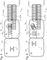
- Figures 1 to 9 show schematically a time sequence of a method according to the invention for handling piece goods moved in at least one row one behind the other by a corresponding handling device in a view from above.
- Figures 10 to 14 show schematically a time sequence of a method according to the invention for handling piece goods moved in at least one row one behind the other using a corresponding handling device analogous to that Figures 1 to 9 in a side view.
- Figures 15 to 20 show schematically a time sequence of a further embodiment of a method not according to the invention for handling piece goods moved in at least one row one behind the other by a corresponding handling device in a view from above.
- FIGS. 1 to 9 show schematically a time sequence of a method according to the invention for handling piece goods 2 moved one behind the other in at least one row 1 by a corresponding handling device 10 in a view from above, while the Figures 10 to 15 in a schematic manner a time sequence of a method according to the invention analogous to that Figures 1 to 9 show in a side view.
- the process step shown in Fig. 1 illustrated process step; Fig. 11 corresponds Fig. 3 , Fig. 12 corresponds Fig. 4 , Fig. 13 corresponds approximately Fig. 6 and Fig. 14 corresponds Fig. 7 .
- the handling device 10 comprises at least a first transport device 3 for feeding the piece goods 2.
- a first transport device 3 for feeding the piece goods 2.
- two parallel transport devices 3, 3a, 3b are provided, via which directly successive piece goods 2 are fed in two parallel rows 1, 1a, 1b without interruption and/or at a continuous transport speed v3 in a transport direction TR as a so-called closed formation F, Fa, Fb.
- F, Fa, Fb a so-called closed formation
- the handling device 10 to 14 In the illustrated embodiment of the handling device 10, for example, only one transport device 3 is provided.
- the transport devices 3, 3a, 3b can, for example, each be formed by a conveyor belt or another suitable conveyor device on which the piece goods 2 are preferably transported in a single row, with no or only a slight gap, possibly process-related, between each piece goods 2 that follow one another directly or distance exists.
- the handling device 10 comprises a first grouping module 20 and a second grouping module 30 arranged in alignment behind the first grouping module 20 in the transport direction TR Figures 10 to 14 only the first grouping module 20 is shown.
- Each of the two grouping modules 20, 30 is equipped with a movable, displaceable and/or rotatable manipulator.
- the first grouping module 20 includes a first manipulator 21 and the second grouping module 30 includes a second manipulator 31.
- the manipulators 21, 31 are each assigned a detection area within the grouping modules 20, 30, a first detection area 22 of the first manipulator 21 and a second detection area 32 of the second manipulator 31. At least some of the piece goods 2 are within the first detection area 22 by the first Manipulator 21 detected, spatially separated from the subsequent piece goods 2 of the closed formation F, Fa, Fb and placed in a first target position and / or target arrangement P1 within the first detection area 22. Furthermore, at least some of the piece goods 2 are detected in the second detection area 32 by the second manipulator 31 and brought into a second target position and/or target arrangement P2 within the second detection area 32.
- the piece goods 2 are each transported via the transport device(s) 3, 3a, 3 to the first detection area 22.
- the first grouping module 20 comprises a first horizontal conveyor device 23, which, like the transport device 3, is formed, for example, by an endless conveyor belt.
- the piece goods 2 supplied in at least one row 1 via the at least one transport device 3 are influenced by the dynamic pressure of the subsequent piece goods 2 are pushed over to the first horizontal conveyor device 23 and transported there without interruption.
- the piece goods 2 arriving from the first transport device 3 into the first detection area 22 are transported via the first
- Horizontal conveyor 23 moves further in the transport direction TR.
- the piece goods 2 are preferably conveyed continuously and without gaps by the first horizontal conveyor device 23 at a speed which corresponds to the transport speed v3 of the transport device(s) 3, 3a, 3b.
- At least the first manipulator 21 of the first grouping module 20, but in particular both manipulators 21, 31, is/are designed for clamping and/or non-positive and/or form-fitting receipt of piece goods 2 within the respective detection area 22, 32.
- the first manipulator 21 detects piece goods 2 from a row 1, 1a, 1b of piece goods 2 supplied without gaps into the first detection area 22.
- the first manipulator 21 does not detect the frontmost piece goods 2 of the row 1, 1a, 1b, but rather attacks piece goods 2 of at least one row 1, 1a, 1b which are at least one in the transport direction TR TR follow general cargo 2, 2v in rows 1, 1a, 1b.
- the at least one piece of goods 2 ahead of the detected piece of goods 2 is identified below with the reference number 2v.
- the piece goods 2 detected by the first manipulator 21 and the piece goods 2v leading in the transport direction TR are spatially separated from the following piece goods 2 of the formation F.
- the piece goods 2 detected by the first manipulator serve to move the at least one further piece goods 2v of rows 1, 1a, 1b that are leading in the transport direction (see Figures 4 and 12 ).
- the at least one leading piece of goods 2v not detected by the first manipulator 21 is pushed into a first position T within the first detection area 22, the displacement of the at least one leading piece goods 2v takes place at least temporarily together with the at least one piece goods 2 detected by the first manipulator 21.
- the piece goods 2 detected by the first manipulator 21 are then brought into a desired first target position and/or target arrangement P1 within the first detection area 22 of the first manipulator 21 of the first grouping module 20.
- a rotational movement of the first manipulator 21 can take place about a preferably approximately vertical axis, so that the piece goods 2 detected by the first manipulator 21 or the group of at least two piece goods 2 are rotated accordingly.
- a rotation of 90 degrees takes place, so that the piece goods 2 released by the first manipulator 21 in the first target position and/or target arrangement P1 have an orientation rotated by 90 degrees relative to the subsequent piece goods 2 of the closed formation F.
- a lateral displacement of the at least one piece goods 2 detected by the first manipulator 21 can be provided, so that the piece goods 2 released by the first manipulator 21 in the first target position and/or target arrangement P1 have the same orientation as the piece goods 2 of the closed formation F maintained, but no longer move in alignment with the following piece goods 2 of the closed formation F.
- the piece goods 2 detected by means of the first manipulator 21 are brought directly into a respective first target position and/or target orientation P1 without being released in the meantime by the first manipulator 21.
- the feeding transport device 3 and the first horizontal conveyor device 23 continue to be operated constantly.
- the speed v3 is selected so that the first manipulator 21 has sufficient time within the working area available to it, in particular within its first detection area 22, to handle and move the piece goods 2 and / or.
- the first manipulator 21 preferably consists of a delta kinematics robot, a tripod or similar in order to realize highly dynamic displacement movements and to enable the fastest possible cycle times.
- these leading piece goods 2v are fed to the second grouping module 30 in alignment with the row 1 of the piece goods 2 on the transport device 3 and thus reach the second detection area 32 of the second manipulator 31 ( Fig. 7 ).
- At least one of the leading piece goods 2 or the group of the leading piece goods 2 is/are detected within the second detection area 32 by the second manipulator 31 and brought into a second target position and/or target arrangement P2 within the second grouping module ( Fig. 9 ).
- the feeding transport device 3 the first horizontal conveyor device 23 and the second horizontal conveyor device 33 continue to be constant operated.
- the speed v3 is chosen so that both manipulators 21, 31 have sufficient time within the work areas available to them to handle and/or move the piece goods 2 accordingly, etc.
- the first manipulator 21 puts together at least one first layer arrangement or piece goods layer from a plurality of piece goods 2 within the first detection area 22.
- This piece goods layer can still have gaps between the piece goods 2, which, after passing through the second grouping module 30, is completed as a compact layer in a subsequent palletizing module (not shown) by pushing the piece goods together before the subsequent palletizing.
- At least one second palletizable layer arrangement or piece of cargo is assembled by the second manipulator 31 from a plurality of piece goods 2 within the second detection area 32 and fed to the subsequent palletizing module.
- An alternative embodiment can provide that the arrangement of piece goods 2 by the first manipulator 21 in the first grouping module 20 and the second manipulator 31 in the second grouping module 30 to form a common General cargo layer is used, which is then fed to the palletizing module for further processing.
- FIG. 1 A control device 100 is also shown, which is electronically coupled to the first manipulator 21 and the second manipulator 31 and contains information about the method steps to be carried out using the first manipulator 21 and the second manipulator 31 and controls them accordingly.
- FIGS 15 to 20 show schematically a time sequence of an embodiment of a method not according to the invention for handling piece goods 2 moved one behind the other in at least one row 1 by a corresponding handling device 10 in a view from above.
- piece goods 2 are fed via a transport device 3 as a gapless formation F in a row 1.
- the first manipulator 21 of the first grouping module 20 detects three piece goods 2 from the formation F ( Fig. 15 ) and moves them laterally out of the closed formation F, so that a gap is formed between the closed formation F and the piece goods 2v, which are ahead of the recorded piece goods 2 ( Fig. 16 ).
- the leading piece goods 2v move continuously in the transport direction TR in the direction of the second grouping module 30, in particular the leading piece goods 2v are moved continuously at the conveying speed of the first horizontal conveyor 23.
- the first manipulator 21 detects two further piece goods 2 of the closed formation F entering the first grouping module 20 and separates these piece goods 2 from the closed formation F, with the first manipulator 21 additionally rotating the two recorded piece goods 2 by 90 degrees and into one Target position and/or target arrangement P is spent laterally to the alignment of the closed formation F and laterally to the piece goods 2v that are not detected in the first method step and are ahead in the transport direction TR ( Figures 17 and 18 ).
- the leading piece goods 2v are fed to the second grouping module 30 and thus reach the second detection area 32 of the second manipulator 31.
- the second manipulator 31 detects at least one of the leading piece goods 2v ( Fig. 20 ) in order to move this or the group of at least two leading piece goods 2v into a target position and / or target arrangement within the second detection area 32 according to a predetermined position scheme (not shown).
- piece goods 2 are at least partially handled and manipulated in the second grouping module 30, which only pass through the first grouping module 20 in alignment with the closed formation F in the transport direction TR.
- the piece goods 2 handled in the second grouping module 30 are not manipulated by the first manipulator 21 in a direct or indirect manner within the first grouping module 20.
- a central control device 100 is also shown, which is coupled to further control units of the device 10, in particular to a first control unit 101 assigned to the first manipulator 21 and to a second control unit 102 assigned to the second manipulator 31.
- the central control device 100 transmits the corresponding information to the first control unit 101, which then controls the first manipulator 21 accordingly and/or the control device 100 transmits the corresponding information to the second control unit 102, which then controls the second manipulator 31 accordingly.
- piece goods 2 can be handled in the second grouping module 30, which have passed through the first grouping module 20 without manipulation or which have been shifted in alignment in the transport direction TR in the first grouping module 20 by trailing piece goods 2 and thus indirectly by the first manipulator 21.
- the piece goods 2 can be brought into a first intermediate position and/or intermediate arrangement both in the first grouping module 20 by the first manipulator 21 and then into a target position and/or target arrangement in the second grouping module 30 by the second manipulator 31 be spent in a predetermined layer scheme (not shown).
Claims (11)
- Procédé de manipulation de produits de détail (2) déplacées les uns derrière les autres en au moins une rangée (1), dans lequel- les produits de détail (2) sont amenés, en se suivent immédiatement sans espacement, en tant que formation fermée (F) dans une direction de transport (TR) à un premier module de manipulation (20) comprenant un premier manipulateur (21) destiné à manipuler des produits de détail (2) dans une première zone de saisie (22) associée au premier manipulateur (21);- dans lequel au moins une partie des produits de détail (2) amenés en formation fermée (F) est saisie dans le premier module de manipulation (20) par le premier manipulateur (21) et est amenée dans une première position cible et/ou premier agencement cible (P1) à l'intérieur de la première zone de saisie (22);- dans lequel le premier manipulateur (21) saisit par serrage et/ou par adhérence et/ou à engagement positif au moins un produit de détail (2) de la formation fermée (F);- et dans lequel au moins une partie des produits de détail (2) amenés est saisie par un deuxième manipulateur (31) dans un deuxième module de manipulation (30) qui est disposé en aval et de manière alignée, au moins par zones, du premier module de manipulation (20) dans la direction de transport (TR), et qui comprend ledit deuxième manipulateur (31) destiné à manipuler des produits de détail (2) dans une deuxième zone de saisie (32) associée au deuxième manipulateur (31), et est amenée dans une deuxième position cible et/ou un deuxième agencement cible (P2) à l'intérieur de la deuxième zone de saisie (32),- dans lequel une première partie de produits de détail (2) manipulée dans le premier module de manipulation (20) comprend au moins en partie une deuxième partie de produits de détail (2) manipulée dans le deuxième module de manipulation (30),- au moins un produit de détail (2) de la formation fermée (F) est saisi par le premier manipulateur (21), est séparé spatialement de la formation fermée (F) et est amené dans une position cible et/ou orientation cible (P1) rélative(s) définie(s) par rapport à des produits de détail (2) suivants,
caractérisé par le fait que- en amont dudit au moins un produit de détail (2) saisi est situé au moins un autre produit de détail (2) de la formation fermée (F) non saisi par le premier manipulateur (21), qui est poussé temporairement conjointement avec ledit au moins un produit de détail saisi (2) dans une première position (T) à l'intérieur de la première zone de saisie (22),- dans lequel, après que ledit au moins un produit de détail (2) non saisi a été amené par le premier manipulateur (21) dans la première position (T), ledit au moins un produit de détail (2) saisi par le premier manipulateur (21) est amené par le manipulateur (21) dans la première position cible et/ou orientation cible (P1) et est libéré dans celle-ci, dans lequel la première position cible et/ou orientation cible (P1) est réalisée à distance de la première position (T). - Procédé selon la revendication 1, dans lequel le premier manipulateur (21) se synchronise avec des produits de détail (2) d'un deuxième cycle de produits de détail, lesquels sont disposés en aval de produits de détail (2) d'un premier cycle de produits de détail,lesquels produits de détail (2) du premier cycle de produits de détail sont saisis et manipulés par le deuxième manipulateur (31) oulesquels produits de détail (2) du premier cycle de produits de détail forment des produits de passage qui ne sont pas maniés et manipulés à l'intérieur du deuxième module de manipulation (30), car le positionnement relatif est déjà suffisant pour le traitement ultérieur suivant, en particulier la palettisation.
- Procédé selon la revendication 2, dans lequel la séparation s'effectue en déplaçant, au moins temporairement, le produit de détail (2) saisi par le premier manipulateur (21) dans la direction de transport (TR), en alignement avec la formation fermée (F), à une vitesse augmentée par rapport à la formation fermée, dans lequel, en déplaçant ledit au moins un produit de détail (2) saisi dans la direction de transport (TR), en sus ledit au moins un produit de détail (2) qui est disposé en amont du produit de détail (2) saisi dans la direction de transport (TR) est déplacé conjointement avec ce dernier également dans la direction de transport (TR).
- Procédé selon l'une quelconque des revendications précédentes, dans lequel le deuxième manipulateur (31) saisit par serrage et/ou par adhérence et/ou à engagement positif à l'intérieur de la deuxième zone de saisie (32) au moins un produit de détail (2) entrant dans la deuxième zone de saisie (32) et amène celui-ci dans une deuxième position cible et/ou un deuxième agencement cible (P2) à l'intérieur de la deuxième zone de saisie (32).
- Procédé selon l'une quelconque des revendications précédentes, dans lequel on continue à déplacer en continu les produits de détail (2) amenés dans une position cible et/ou un agencement cible, dans la direction de transport (TR) à l'intérieur de la première zone de saisie (22) et/ou à l'intérieur de la deuxième zone de saisie (32), en particulier à une vitesse de transport qui correspond à la vitesse de transport (v3) des produits de détail (2) de la formation fermée (F).
- Procédé selon l'une quelconque des revendications précédentes, dans lequel une partie de produits de détail (2) manipulée dans le deuxième module de manipulation (30) ne correspond pas à une partie de produits de détail (2) manipulée dans le premier module de manipulation (20).
- Procédé selon l'une quelconque des revendications précédentes, dans lequel au moins un agencement de couches palettisable ou une couche de produits de détail palettisable est assemblé(e) à partir d'une pluralité de produits de détail (2) à l'intérieur de la première zone de saisie (22) et/ou à l'intérieur de la deuxième zone de saisie (32).
- Procédé selon l'une quelconque des revendications précédentes, dans lequel ledit au moins un produit de détail (2) disposé dans la première position (T) ou la première position cible et/ou le premier agencement cible (P1) fait partie d'une première couche de produits de détail palettisable formée à l'intérieur du premier module de manipulation (20) et/ou dans lequel ledit au moins un produit de détail (2) disposé dans la première position (T) et non saisi par le premier manipulateur (21) est saisi par le deuxième manipulateur (31) après être entré dans la deuxième zone de saisie (32) et est amené dans une deuxième position cible et/ou orientation cible (P2) à l'intérieur de la deuxième zone de saisie (32), dans lequel ledit au moins un produit de détail (2) disposé dans la deuxième position cible et/ou le deuxième agencement cible (P2) fait partie d'une deuxième couche de produits de détail palettisable formée à l'intérieur du deuxième module de manipulation (30).
- Procédé selon l'une quelconque des revendications 1 à 8, dans lequel ledit au moins un produit de détail (2) saisi par le premier manipulateur (21) et ledit au moins un produit de détail (2v) situé en amont et non saisi par le premier manipulateur (21) font chacun partie d'une couche de produits de détail palettisable formée en commun à l'intérieur du premier module de manipulation (20) et du deuxième module de manipulation (30).
- Dispositif (10) de mise en oeuvre d'un procédé de manipulation de produits de détail (2) déplacés les uns derrière les autres en au moins une rangée (1), comprenant- au moins un dispositif de transport (3) par l'intermédiaire duquel des produits de détail (2) immédiatement successifs de la rangée (1) peuvent être amenés sans espacement, en tant que formation fermée (F), dans une direction de transport (TR),- au moins un premier module de manipulation (20) comprenant un premier manipulateur (21) destiné à manipuler les produits de détail (2) ainsi qu'une première zone de saisie (22) associée au premier manipulateur (21),- dans lequel le premier manipulateur (21) est conçu pour recevoir par serrage et/ou par adhérence et/ou à engagement positif au moins un produit de détail (2) de la formation fermée (F) transportée au moyen dudit au moins un dispositif de transport (3) dans sa première zone de saisie (22), ainsi que pour séparer spatialement ledit au moins un produit de détail (2) de la formation fermée (F) et pour transférer ledit au moins un produit de détail (2) dans une première position cible et/ou orientation cible (P1) à l'intérieur de la première zone de saisie (22),- et dans lequel ledit premier manipulateur (21) est conçu pour saisir au moins un produit de détail (2) situé en aval d'un produit de détail (2) de la formation fermée (F), qui est situé en premier, de sorte que ledit premier manipulateur (21) laisse ledit au moins un produit de détail (2) situé en premier, sans saisir celui-ci, et- dans lequel ledit premier manipulateur (21) est conçu pour pousser ledit au moins un produit de détail (2) situé en premier dans une première position (T) respective prévue pour le produit de détail (2) situé en premier,- au moins un deuxième module de manipulation (30) qui est disposé en aval et de manière alignée, au moins par zones, du premier module de manipulation (20) dans la direction de transport (TR), et qui comprend un deuxième manipulateur (31) destiné à manipuler les produits de détail (2) et une deuxième zone de saisie (32) associée au deuxième manipulateur (31),
caractérisé par le fait que- le dispositif (10) comprend en outre un dispositif de commande (100), lequel dispositif de commande (100) est conçu pour commander le premier manipulateur (21) et le deuxième manipulateur (31) pour mettre en oeuvre le procédé selon l'une quelconque des revendications 1 à 9. - Dispositif (10) selon la revendication 10, dans lequel le deuxième manipulateur (31) est conçu pour recevoir par serrage et/ou par adhérence et/ou à engagement positif au moins un produit de détail (2) entrant dans la deuxième zone de saisie (32) depuis la première zone de saisie (22), ainsi que pour transférer ledit au moins un produit de détail (2) dans une deuxième position cible et/ou orientation cible (P2) à l'intérieur de la deuxième zone de saisie (32).
Applications Claiming Priority (1)
| Application Number | Priority Date | Filing Date | Title |
|---|---|---|---|
| DE102019120288.4A DE102019120288A1 (de) | 2019-07-26 | 2019-07-26 | Verfahren und Vorrichtung zum Umgang mit in mindestens einer Reihe hintereinander bewegten Stückgütern |
Publications (3)
| Publication Number | Publication Date |
|---|---|
| EP3770086A1 EP3770086A1 (fr) | 2021-01-27 |
| EP3770086B1 true EP3770086B1 (fr) | 2023-10-18 |
| EP3770086C0 EP3770086C0 (fr) | 2023-10-18 |
Family
ID=71111212
Family Applications (1)
| Application Number | Title | Priority Date | Filing Date |
|---|---|---|---|
| EP20180873.0A Active EP3770086B1 (fr) | 2019-07-26 | 2020-06-18 | Procédé et dispositif de manipulation des marchandises déplacées les unes après les autres dans au moins une rangée |
Country Status (3)
| Country | Link |
|---|---|
| EP (1) | EP3770086B1 (fr) |
| CN (1) | CN214030707U (fr) |
| DE (1) | DE102019120288A1 (fr) |
Families Citing this family (1)
| Publication number | Priority date | Publication date | Assignee | Title |
|---|---|---|---|---|
| CN114671093B (zh) * | 2022-05-26 | 2022-08-26 | 四川远方云天食品科技有限公司 | 基于图像识别的食品包装实时检测装置、系统及方法 |
Family Cites Families (13)
| Publication number | Priority date | Publication date | Assignee | Title |
|---|---|---|---|---|
| US5123231A (en) | 1990-10-31 | 1992-06-23 | Fallas David M | Product grouping and packing apparatus and method |
| JP4490642B2 (ja) | 2003-04-01 | 2010-06-30 | 株式会社根本杏林堂 | 薬液注入装置 |
| AU2004201709A1 (en) * | 2004-04-23 | 2005-11-10 | Foodmach Pty Ltd | Materials handling system |
| DE102005023859B4 (de) | 2005-05-24 | 2007-04-19 | Schaefer Förderanlagen- und Maschinenbau GmbH | Gruppiertisch zum Zusammenführen von Gebinden |
| EP2107018B2 (fr) * | 2008-04-04 | 2016-01-27 | Krones AG | Dispositif d'assemblage et d'alignement de groupes de gerbes |
| DE102009003845A1 (de) * | 2009-04-29 | 2010-11-04 | Krones Ag | Vorrichtung und Verfahren zum definierten Zusammenführen von Gebinden und/oder Gebindegruppen |
| DE102009026220B4 (de) | 2009-07-22 | 2023-11-30 | Krones Aktiengesellschaft | Verfahren und Verpackungsmaschine zum Gruppieren und Verbinden von Artikeln |
| DE102009043970A1 (de) | 2009-09-10 | 2011-03-17 | Krones Ag | Modul für eine Verpackungsstrasse und/oder eine Gruppiereinheit |
| DE102010020847A1 (de) | 2010-05-18 | 2011-11-24 | Krones Ag | Greifvorrichtung |
| DE102011080812A1 (de) * | 2011-08-11 | 2013-02-14 | Krones Aktiengesellschaft | Verfahren und Vorrichtung zur Bildung von Lagen aus Artikeln, Stückgütern oder Gebinden |
| DE102016206667A1 (de) * | 2016-04-20 | 2017-10-26 | Krones Aktiengesellschaft | Verfahren und Vorrichtung zum Umgang mit in mindestens einer Reihe hintereinander bewegten Stückgütern |
| DE102016125361A1 (de) * | 2016-12-22 | 2018-06-28 | Krones Aktiengesellschaft | Handhabungssystem und Verfahren zum Umgang mit Stückgütern |
| DE102017215320A1 (de) * | 2017-09-01 | 2019-03-07 | Krones Aktiengesellschaft | Verfahren und Vorrichtung zum Umgang mit in mindestens einer Reihe hintereinander bewegten Stückgütern |
-
2019
- 2019-07-26 DE DE102019120288.4A patent/DE102019120288A1/de active Pending
-
2020
- 2020-06-18 EP EP20180873.0A patent/EP3770086B1/fr active Active
- 2020-06-22 CN CN202021170788.8U patent/CN214030707U/zh active Active
Also Published As
| Publication number | Publication date |
|---|---|
| DE102019120288A1 (de) | 2021-01-28 |
| EP3770086A1 (fr) | 2021-01-27 |
| EP3770086C0 (fr) | 2023-10-18 |
| CN214030707U (zh) | 2021-08-24 |
Similar Documents
| Publication | Publication Date | Title |
|---|---|---|
| EP3445692B1 (fr) | Procédé et dispositif permettant la manutention de marchandises de détail déplacées sur au moins deux rangées parallèles | |
| EP3554972B1 (fr) | Dispositif et procédé de manutention de charges isolées déplacées les unes derrière les autres | |
| EP3475198B1 (fr) | Procédé et dispositif permettant la manutention de marchandises de détail déplacées les unes derrière les autres en au moins une rangée | |
| EP3475199B1 (fr) | Procédé et dispositif de manutention de charges isolées déplacées les unes derrière les autres en au moins une rangée | |
| EP3652092A1 (fr) | Procédé et dispositif de manipulation de marchandises de détail, d'articles et/ou d'emballages | |
| EP3445683B1 (fr) | Procédé pour la manutention de marchandises de détail déplacées les unes derrière les autres | |
| EP3652094B1 (fr) | Procédé et appareil pour la manutention de marchandises, d'articles et/ou d'emballages | |
| EP3652093B1 (fr) | Procédé et dispositif pour manipuler des marchandises, articles et/ou paquets | |
| EP3445691A1 (fr) | Procédé et dispositif pour la manutention de marchandises de détail déplacées les unes derrière les autres en au moins une rangée | |
| EP3445686A1 (fr) | Procédé et dispositif permettant la manutention de marchandises de détail déplacées les unes après les autres sur au moins une rangée | |
| EP3770086B1 (fr) | Procédé et dispositif de manipulation des marchandises déplacées les unes après les autres dans au moins une rangée | |
| EP3487796A1 (fr) | Procédé et dispositif pour la manutention de marchandises de détail déplacées les unes derrières les autres sur au moins une file | |
| EP3623323A1 (fr) | Procédé et dispositif de manipulation des marchandises, des articles et / ou des emballages | |
| EP3378803A1 (fr) | Dispositif et procédé de manipulation d'au moins une rangée de marchandises en mouvement les unes derrière les autres | |
| EP3676203A1 (fr) | Procédé et dispositif permettant la manutention de marchandises de détail déplacées les unes derrière les autres en au moins une rangée | |
| EP3770085A1 (fr) | Procédé et dispositif de manipulation de marchandises déplacées les unes après les autres dans au moins une rangée | |
| WO2019076708A1 (fr) | Procédé et dispositif de manipulation et/ou de regroupement de marchandises de détail | |
| EP3378804A1 (fr) | Dispositif et procédé de manipulation d'au moins une rangée de marchandises en mouvement | |
| EP3475200B1 (fr) | Procédé et dispositif de manutention de charges isolées déplacées les unes derrière les autres | |
| EP3445689B1 (fr) | Procédé pour manipuler au moins une ligne de marchandises déplacées les unes derrière les autres | |
| EP3532412A1 (fr) | Procédé et dispositif pour produire un groupement composé d'une pluralité de charges isolées et installation équipée d'un tel dispositif | |
| WO2019011579A1 (fr) | Procédé et dispositif pour manipuler des marchandises, articles et/ou paquets |
Legal Events
| Date | Code | Title | Description |
|---|---|---|---|
| PUAI | Public reference made under article 153(3) epc to a published international application that has entered the european phase |
Free format text: ORIGINAL CODE: 0009012 |
|
| STAA | Information on the status of an ep patent application or granted ep patent |
Free format text: STATUS: THE APPLICATION HAS BEEN PUBLISHED |
|
| AK | Designated contracting states |
Kind code of ref document: A1 Designated state(s): AL AT BE BG CH CY CZ DE DK EE ES FI FR GB GR HR HU IE IS IT LI LT LU LV MC MK MT NL NO PL PT RO RS SE SI SK SM TR |
|
| AX | Request for extension of the european patent |
Extension state: BA ME |
|
| STAA | Information on the status of an ep patent application or granted ep patent |
Free format text: STATUS: REQUEST FOR EXAMINATION WAS MADE |
|
| 17P | Request for examination filed |
Effective date: 20210720 |
|
| RBV | Designated contracting states (corrected) |
Designated state(s): AL AT BE BG CH CY CZ DE DK EE ES FI FR GB GR HR HU IE IS IT LI LT LU LV MC MK MT NL NO PL PT RO RS SE SI SK SM TR |
|
| GRAP | Despatch of communication of intention to grant a patent |
Free format text: ORIGINAL CODE: EPIDOSNIGR1 |
|
| STAA | Information on the status of an ep patent application or granted ep patent |
Free format text: STATUS: GRANT OF PATENT IS INTENDED |
|
| GRAJ | Information related to disapproval of communication of intention to grant by the applicant or resumption of examination proceedings by the epo deleted |
Free format text: ORIGINAL CODE: EPIDOSDIGR1 |
|
| STAA | Information on the status of an ep patent application or granted ep patent |
Free format text: STATUS: REQUEST FOR EXAMINATION WAS MADE |
|
| INTG | Intention to grant announced |
Effective date: 20230421 |
|
| GRAP | Despatch of communication of intention to grant a patent |
Free format text: ORIGINAL CODE: EPIDOSNIGR1 |
|
| STAA | Information on the status of an ep patent application or granted ep patent |
Free format text: STATUS: GRANT OF PATENT IS INTENDED |
|
| INTC | Intention to grant announced (deleted) | ||
| INTG | Intention to grant announced |
Effective date: 20230531 |
|
| P01 | Opt-out of the competence of the unified patent court (upc) registered |
Effective date: 20230523 |
|
| GRAS | Grant fee paid |
Free format text: ORIGINAL CODE: EPIDOSNIGR3 |
|
| GRAA | (expected) grant |
Free format text: ORIGINAL CODE: 0009210 |
|
| STAA | Information on the status of an ep patent application or granted ep patent |
Free format text: STATUS: THE PATENT HAS BEEN GRANTED |
|
| AK | Designated contracting states |
Kind code of ref document: B1 Designated state(s): AL AT BE BG CH CY CZ DE DK EE ES FI FR GB GR HR HU IE IS IT LI LT LU LV MC MK MT NL NO PL PT RO RS SE SI SK SM TR |
|
| REG | Reference to a national code |
Ref country code: GB Ref legal event code: FG4D Free format text: NOT ENGLISH |
|
| REG | Reference to a national code |
Ref country code: CH Ref legal event code: EP |
|
| REG | Reference to a national code |
Ref country code: DE Ref legal event code: R096 Ref document number: 502020005670 Country of ref document: DE |
|
| REG | Reference to a national code |
Ref country code: IE Ref legal event code: FG4D Free format text: LANGUAGE OF EP DOCUMENT: GERMAN |
|
| U01 | Request for unitary effect filed |
Effective date: 20231025 |
|
| U07 | Unitary effect registered |
Designated state(s): AT BE BG DE DK EE FI FR IT LT LU LV MT NL PT SE SI Effective date: 20231031 |
|
| P04 | Withdrawal of opt-out of the competence of the unified patent court (upc) registered |
Effective date: 20231027 |
|
| PG25 | Lapsed in a contracting state [announced via postgrant information from national office to epo] |
Ref country code: GR Free format text: LAPSE BECAUSE OF FAILURE TO SUBMIT A TRANSLATION OF THE DESCRIPTION OR TO PAY THE FEE WITHIN THE PRESCRIBED TIME-LIMIT Effective date: 20240119 |
|
| PG25 | Lapsed in a contracting state [announced via postgrant information from national office to epo] |
Ref country code: IS Free format text: LAPSE BECAUSE OF FAILURE TO SUBMIT A TRANSLATION OF THE DESCRIPTION OR TO PAY THE FEE WITHIN THE PRESCRIBED TIME-LIMIT Effective date: 20240218 |