EP3770080A1 - Banding band - Google Patents
Banding band Download PDFInfo
- Publication number
- EP3770080A1 EP3770080A1 EP19770373.9A EP19770373A EP3770080A1 EP 3770080 A1 EP3770080 A1 EP 3770080A1 EP 19770373 A EP19770373 A EP 19770373A EP 3770080 A1 EP3770080 A1 EP 3770080A1
- Authority
- EP
- European Patent Office
- Prior art keywords
- belt
- banding band
- group
- polyethersulfone
- banding
- Prior art date
- Legal status (The legal status is an assumption and is not a legal conclusion. Google has not performed a legal analysis and makes no representation as to the accuracy of the status listed.)
- Granted
Links
Images


Classifications
-
- B—PERFORMING OPERATIONS; TRANSPORTING
- B65—CONVEYING; PACKING; STORING; HANDLING THIN OR FILAMENTARY MATERIAL
- B65D—CONTAINERS FOR STORAGE OR TRANSPORT OF ARTICLES OR MATERIALS, e.g. BAGS, BARRELS, BOTTLES, BOXES, CANS, CARTONS, CRATES, DRUMS, JARS, TANKS, HOPPERS, FORWARDING CONTAINERS; ACCESSORIES, CLOSURES, OR FITTINGS THEREFOR; PACKAGING ELEMENTS; PACKAGES
- B65D63/00—Flexible elongated elements, e.g. straps, for bundling or supporting articles
- B65D63/10—Non-metallic straps, tapes, or bands; Filamentary elements, e.g. strings, threads or wires; Joints between ends thereof
- B65D63/1018—Joints produced by application of integral securing members, e.g. buckles, wedges, tongue and slot, locking head and teeth or the like
- B65D63/1027—Joints produced by application of integral securing members, e.g. buckles, wedges, tongue and slot, locking head and teeth or the like the integral securing member being formed as a female and male locking member, e.g. locking head and locking teeth, or the like
- B65D63/1063—Joints produced by application of integral securing members, e.g. buckles, wedges, tongue and slot, locking head and teeth or the like the integral securing member being formed as a female and male locking member, e.g. locking head and locking teeth, or the like the female locking member being provided with at least one plastic barb
- B65D63/1072—Joints produced by application of integral securing members, e.g. buckles, wedges, tongue and slot, locking head and teeth or the like the integral securing member being formed as a female and male locking member, e.g. locking head and locking teeth, or the like the female locking member being provided with at least one plastic barb the barb having a plurality of serrations
-
- C—CHEMISTRY; METALLURGY
- C08—ORGANIC MACROMOLECULAR COMPOUNDS; THEIR PREPARATION OR CHEMICAL WORKING-UP; COMPOSITIONS BASED THEREON
- C08L—COMPOSITIONS OF MACROMOLECULAR COMPOUNDS
- C08L71/00—Compositions of polyethers obtained by reactions forming an ether link in the main chain; Compositions of derivatives of such polymers
- C08L71/02—Polyalkylene oxides
-
- C—CHEMISTRY; METALLURGY
- C08—ORGANIC MACROMOLECULAR COMPOUNDS; THEIR PREPARATION OR CHEMICAL WORKING-UP; COMPOSITIONS BASED THEREON
- C08L—COMPOSITIONS OF MACROMOLECULAR COMPOUNDS
- C08L79/00—Compositions of macromolecular compounds obtained by reactions forming in the main chain of the macromolecule a linkage containing nitrogen with or without oxygen or carbon only, not provided for in groups C08L61/00 - C08L77/00
- C08L79/04—Polycondensates having nitrogen-containing heterocyclic rings in the main chain; Polyhydrazides; Polyamide acids or similar polyimide precursors
- C08L79/08—Polyimides; Polyester-imides; Polyamide-imides; Polyamide acids or similar polyimide precursors
-
- C—CHEMISTRY; METALLURGY
- C08—ORGANIC MACROMOLECULAR COMPOUNDS; THEIR PREPARATION OR CHEMICAL WORKING-UP; COMPOSITIONS BASED THEREON
- C08G—MACROMOLECULAR COMPOUNDS OBTAINED OTHERWISE THAN BY REACTIONS ONLY INVOLVING UNSATURATED CARBON-TO-CARBON BONDS
- C08G73/00—Macromolecular compounds obtained by reactions forming a linkage containing nitrogen with or without oxygen or carbon in the main chain of the macromolecule, not provided for in groups C08G12/00 - C08G71/00
- C08G73/06—Polycondensates having nitrogen-containing heterocyclic rings in the main chain of the macromolecule
- C08G73/10—Polyimides; Polyester-imides; Polyamide-imides; Polyamide acids or similar polyimide precursors
- C08G73/1046—Polyimides containing oxygen in the form of ether bonds in the main chain
-
- C—CHEMISTRY; METALLURGY
- C08—ORGANIC MACROMOLECULAR COMPOUNDS; THEIR PREPARATION OR CHEMICAL WORKING-UP; COMPOSITIONS BASED THEREON
- C08G—MACROMOLECULAR COMPOUNDS OBTAINED OTHERWISE THAN BY REACTIONS ONLY INVOLVING UNSATURATED CARBON-TO-CARBON BONDS
- C08G75/00—Macromolecular compounds obtained by reactions forming a linkage containing sulfur with or without nitrogen, oxygen, or carbon in the main chain of the macromolecule
- C08G75/20—Polysulfones
- C08G75/23—Polyethersulfones
Definitions
- the present invention relates to a banding band.
- Banding bands are used for bundling long products such as cables and wiring cords, for tying bag openings, and for packing baggage and the like, and are used in a wide range of fields including the automotive field, the construction field, the household electrical appliances field, the electrical and electronic fields, and the daily commodities field.
- Examples of known materials for these banding bands include crystalline resins including polyamide resins such as nylon 66 and nylon 6 (Patent Document 1).
- heat resistance is evaluated by the tensile strength at high temperature (for example, 180°C or higher), and the ratio (hereinafter also referred to as the retention ratio) of the tensile strength at high temperature (for example, 180°C or higher) relative to the tensile strength at room temperature (23°C).
- the present invention has been developed in light of the above circumstances, and has an object of providing a banding band having high heat resistance that can be used even in high-temperature environments of 180°C or higher.
- the present invention includes the following aspects.
- One aspect of the present invention provides a banding band having high heat resistance.
- the banding band of an embodiment of the present invention is described below based on FIG. 1 to FIG. 4 .
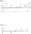
- FIG. 1 is a top view illustrating one example of a banding band of an embodiment of the present invention.
- FIG. 2 is a side view of FIG. 1 .
- FIG. 3 is an enlarged view of a securing portion 13 with a belt-like portion 12 inserted therein.
- the banding band 11 includes the belt-like portion 12, and the securing portion 13 provided at one end 12A of the belt-like portion 12.
- the banding band 11 is a so-called integrated banding band in which the belt-like portion 12 and the securing portion 13 are integrated.
- a through-hole 15 is formed into which the other end 12B of the belt-like portion 12 (the end opposite the end 12A of the belt-like portion 12 where the securing portion 13 is provided) can be inserted.
- a claw 16 which, in combination with a plurality of teeth 14 described below, engages with and fastens the belt-like portion 12.
- the surfaces of the claw 16 that contact the belt-like portion 12 have shapes that correspond with the shapes of the plurality of teeth 14.
- a joint portion 16C of the claw 16 has flexibility.
- the plurality of teeth 14 are formed on one surface 12a of the belt-like portion 12.
- the plurality of teeth 14 are arrayed along the lengthwise direction of the belt-like portion 12.
- the teeth 14 extend outward in the short direction of the belt-like portion 12.
- the teeth 14 are formed with a serrated shape.
- An inclined surface 14a of each tooth 14 faces the other end 12B of the belt-like portion 12.
- the inclined surfaces 14a of the teeth 14 push the claw 16 downward so that linear portions 16A of the claw 16 are forced lower than apexes 14A of the teeth 14, thus allowing movement of the belt-like portion 12 along the insertion direction.
- FIG. 4 is a schematic view describing an example of using the banding band of the present embodiment.
- the belt-like portion 12 of the banding band 11 is wrapped around bundling target objects 17 and then inserted into the through-hole 15 of the securing portion 13 so that the teeth 14 and the claw 16 catch against one another.
- the bundling target objects 17 can be bundled without the belt-like portion 12 retracting from the position at which the teeth 14 and claw 16 have caught.
- the minimum thickness (labeled D in FIG. 3 ) of the belt-like portion 12 is preferably greater than 0 mm but not more than 1.5 mm, and is more preferably 1.2 mm or less. Although there are no particular limitations on the lower limit for the minimum thickness of the belt-like portion 12, from the view point of the moldability, a thickness may be at least 0.5 mm, and is preferably 0.8 mm or greater.
- the minimum thickness of the belt-like portion 12 is preferably at least 0.5 mm but not more than 1. 5mm, and is more preferably at least 0.8 mm but not more than 1.2 mm.
- the "minimum thickness of the belt-like portion” means the minimum distance from the surface of the belt-like portion on the opposite side from the surface on which the plurality of teeth are formed, through to the surface on which the plurality of teeth are formed.
- the minimum thickness of the belt-like portion can be measured using a dial gauge. Further, the minimum thickness of the belt-like portion can also be measured using calipers following cutting of the belt-like portion to an appropriate size.
- the ratio between the thickness of the belt-like portion 12 (namely, the minimum thickness of the belt-like portion) relative to the thickness of the securing portion 13 may be at least 1 but less than 10.
- the "thickness of the securing portion” means the shortest distance from the upper surface to the lower surface of the securing portion when the banding band is placed on a horizontal surface with the surface on which the teeth are formed facing downward.
- the ratio between the length of the belt-like portion 12 in the lengthwise direction (the shortest distance along the lengthwise direction of the belt-like portion 12) and the length of the belt-like portion 12 across the short direction (the shortest distance across the short direction of the belt-like portion 12) may be at least 10 but less than 100.
- the banding band of the present embodiment preferably has a length along the lengthwise direction of 50 to 300 mm, and a length across the short direction of 2 to 10 mm.
- the length of the belt-like portion in the lengthwise direction is preferably from 50 to 300 mm, and the length of the belt-like portion across the short direction (hereinafter sometimes referred to as the "width") is preferably from 2 to 10 mm.
- the length of the securing portion in the same direction as the lengthwise direction of the belt-like portion is preferably from 4 to 15 mm
- the length of the securing portion in the same direction as the short direction of the belt-like portion is preferably from 4 to 15 mm
- the thickness of the securing portion is preferably from 3 to 20 mm.
- the size of the through-hole is preferably from 2 to 10 mm in the same direction as the short direction of the belt-like portion (the width direction), and from 2.5 to 5 mm in the direction perpendicular to the width direction.
- the claw preferably has a height of 1 to 3 mm, and a length in the same direction as the short direction of the belt-like portion (the width direction) of 1.5 to 9.5 mm.
- a structure may be used in which, in order to enable reuse of the banding band, the claw is able to be released from the teeth of the belt-like portion, enabling the belt-like portion to be moved in the withdrawal direction (the direction indicated by an arrow A in FIG. 3 ) at a desired timing.
- the banding band of the present invention need not be the type of integrated banding band illustrated in FIG. 1 , and may be a so-called sectional banding band in which the belt-like portion and the securing portion are separated.
- the states of aggregation of polymer chains can be broadly classified into two states: a state in which the polymer chains are aligned regularly, and a state in which the polymers are wound or intertwined together.
- the former is called a crystalline state, while the latter is called an amorphous or non-crystalline state.
- Resins in which a region of crystalline state exists are classified as crystalline resins, whereas resins in which no region of crystalline state exists are classified as amorphous resins.
- the belt-like portion 12 comprises an amorphous resin having a glass transition temperature of 180°C or higher as a formation material.
- the securing portion 13 preferably comprises an amorphous resin having a glass transition temperature of 180°C or higher as a formation material.
- the glass transition temperature of the amorphous resin is preferably at least 180°C, more preferably at least 190°C, and even more preferably 200°C or higher. Typically, the glass transition temperature of the amorphous resin is not higher than 300°C.
- the belt-like portion in the banding band of the present invention comprises, as a formation material, an amorphous resin having a glass transition temperature of at least 180°C but not more than 300°C, preferably at least 190°C but not more than 300°C, and more preferably at least 200°C but not more than 300°C.
- the amount of the amorphous resin, relative to the total mass of the belt-like portion, is preferably from 80 to 100% by mass, and is more preferably 100% by mass.
- the belt-like portion in the banding band of the present invention may be formed solely from an amorphous resin having a glass transition temperature of at least 180°C but not more than 300°C, preferably at least 190°C but not more than 300°C, and more preferably at least 200°C but not more than 300°C.
- the glass transition temperature can be measured using the method prescribed in JIS-K7121.
- the amorphous resin used in an embodiment of the present invention is preferably at least one resin selected from the group consisting of polysulfones, polyethersulfones, polyetherimides and polyamideimides, is more preferably at least one resin selected from the group consisting of polyethersulfones and polyetherimides, and is even more preferably a polyethersulfone.
- Polyethersulfones are resins having a repeating unit that typically contains a divalent aromatic group (a residue obtained by removing two hydrogen atoms bonded to the aromatic ring of an aromatic compound), a sulfonyl group (-SO 2 -) and an oxygen atom.
- the polyethersulfone preferably has a repeating unit represented by formula (1) shown below (hereinafter sometimes referred to as “repeating unit (1)"), and may also have one or more other repeating units such as a repeating unit represented by formula (2) shown below (hereinafter sometimes referred to as “repeating unit (2)”) or a repeating unit represented by formula (3) shown below (hereinafter sometimes referred to as "repeating unit (3)").
- Ph 1 and Ph 2 each independently represent a phenylene group.
- Each of the hydrogen atoms in the phenylene group may be independently substituted with an alkyl group, an aryl group or a halogen atom.
- Ph 3 and Ph 4 each independently represent a phenylene group.
- Each of the hydrogen atoms in the phenylene group may be independently substituted with an alkyl group, an aryl group or a halogen atom.
- R represents an alkylidene group, an oxygen atom or a sulfur atom.
- Ph 5 represents a phenylene group.
- Each of the hydrogen atoms in the phenylene group may be independently substituted with an alkyl group, an aryl group or a halogen atom.
- n represents an integer of 1 to 3. When n is 2 or greater, the plurality of Ph 5 groups may be the same or different.
- the phenylene group represented by any one of Ph 1 to Ph 5 may be a p-phenylene group, an m-phenylene group or an o-phenylene group, but is preferably a p-phenylene group.
- alkyl group that may substitute a hydrogen atom in the phenylene group include alkyl groups of 1 to 10 carbon atoms, and for example, a methyl group, ethyl group, n-propyl group, isopropyl group, n-butyl group, isobutyl group, s-butyl group, t-butyl group, n-hexyl group, 2-ethylhexyl group, n-octyl group or n-decyl group is preferable.
- Examples of the aryl group that may substitute a hydrogen atom in the phenylene group include aryl groups of 6 to 20 carbon atoms, and for example, a phenyl group, o-tolyl group, m-tolyl group, p-tolyl group, 1-naphthyl group or 2-naphthyl group is preferable.
- the number of these substituent groups per phenylene group is, independently, typically 2 or fewer, and is preferably 1.
- alkylidene group for R examples include alkylidene groups of 1 to 5 carbon atoms, and for example, a methylene group, ethylidene group, isopropylidene group or 1-butylidene group is preferable.
- the polyethersulfone contains the repeating unit (1) in an amount which, relative to the total of all the repeating units (namely, relative to the total amount of all the repeating units that constitute the polyethersulfone), is preferably at least 50 mol% but not more than 100 mol%, and more preferably at least 80 mol% but not more than 100 mol%, and it is even more preferable that the polyethersulfone has substantially only the repeating unit (1) (namely, 95 to 100 mol%) as a repeating unit.
- the polyethersulfone may have two or more types of each of the repeating units (1) to (3).
- the polyethersulfone can be produced by polycondensation of dihalogenosulfone compounds and dihydroxy compounds that correspond with the repeating units that constitute the polyethersulfone.
- a resin having the repeating unit (1) can be produced by using a compound represented by formula (4) shown below (hereinafter sometimes referred to as “compound (4)”) as a dihalogenosulfone compound, and using a compound represented by formula (5) shown below (hereinafter sometimes referred to as “compound (5)”) as a dihydroxy compound.
- compound (4) a compound represented by formula (4) shown below
- compound (5) a compound represented by formula (5) shown below
- a resin having the repeating unit (1) and the repeating unit (2) can be produced by using the compound (4) as a dihalogenosulfone compound, and using a compound represented by formula (6) shown below (hereinafter sometimes referred to as "compound (6)") as a dihydroxy compound.
- a resin having the repeating unit (1) and the repeating unit (3) can be produced by using the compound (4) as a dihalogenosulfone compound, and using a compound represented by formula (7) shown below (hereinafter sometimes referred to as "compound (7)") as a dihydroxy compound.
- X 1 and X 2 each independently represent a halogen atom.
- Ph 1 and Ph 2 are as defined above.
- Ph 1 and Ph 2 are as defined above.
- Ph 3 , Ph 4 and R are as defined above.
- Ph 5 and n are as define above.
- the polycondensation mentioned above is preferably conducted in a solvent using an alkali metal salt of carbonic acid.
- the alkali metal salt of carbonic acid may be an alkali carbonate which is a normal salt, an alkali bicarbonate (also called an alkali hydrogen carbonate) which is an acidic salt, or a mixture of the two, wherein sodium carbonate and potassium carbonate and the like can be used favorably as the alkali carbonate, and sodium bicarbonate and potassium bicarbonate and the like can be used favorably as the alkali bicarbonate.
- solvents that may be used favorably include organic polar solvents such as dimethyl sulfoxide, 1-methyl-2-pyrrolidone, sulfolane (also called 1,1-dioxothiolane), 1,3-dimethyl-2-imidazolidinone, 1,3-diethyl-2-imidazolidinone, dimethyl sulfone, diethyl sulfone, diisopropyl sulfone and diphenyl sulfone.
- organic polar solvents such as dimethyl sulfoxide, 1-methyl-2-pyrrolidone, sulfolane (also called 1,1-dioxothiolane), 1,3-dimethyl-2-imidazolidinone, 1,3-diethyl-2-imidazolidinone, dimethyl sulfone, diethyl sulfone, diisopropyl sulfone and diphenyl sulfone.
- the polyethersulfone has a reduced viscosity that is, for example, at least 0.3 dL/g, preferably at least 0.33 dL/g but not more than 0.45 dL/g, and more preferably at least 0.36 dL/g but not more than 0.41 dL/g.
- the reduced viscosity is at least 0.3 dL/g, the heat resistance and strength and rigidity can be more easily increased.
- the reduced viscosity is not more than 0.45 dL/g, the molding temperature and melt viscosity do not become overly high, and a banding band of the prescribed shape can be molded easily.
- the reduced viscosity can be determined using the method described below in the section entitled "Measurement of Reduced Viscosity”.
- the polyethersulfone may be used in the form of a polyethersulfone composition by adding at least one other component such as a filler, additive or resin other than a polyethersulfone to the polyethersulfone.
- the amount of the polyethersulfone in the polyethersulfone composition, relative to the total mass of the polyethersulfone composition, is preferably within a range from 80 to 100% by mass.
- the belt-like portion in the present invention may be obtained using, as a formation material, a composition comprising an amorphous resin (for example, a polyethersulfone or a polyetherimide) having a glass transition temperature of 180°C or higher, and if desired, also comprising at least one component selected from the group consisting of fillers, additives, and resins other than amorphous resin.
- amorphous resin for example, a polyethersulfone or a polyetherimide
- the filler may be a fibrous filler, a plate-like filler, or filler other than a fibrous filler or plate-like filler such as a spherical filler or other granular filler.
- the filler may be an inorganic filler or an organic filler.
- fibrous inorganic fillers include glass fibers; carbon fibers such as PAN-based carbon fiber and pitch-based carbon fiber, ceramic fibers such as silica fiber, alumina fiber and silica-alumina fiber; and metal fibers such as stainless steel fiber.
- whiskers such as potassium titanate whiskers, barium titanate whiskers, wollastonite whiskers, aluminum borate whiskers, silicon nitride whiskers, and silicon carbide whiskers.
- fibrous organic fillers include polyester fibers and aramid fibers.
- plate-like inorganic fillers include talc, mica, graphite, wollastonite, glass flakes, barium sulfate and calcium carbonate.
- the mica may be muscovite, phlogopite, fluorphlogopite or tetrasilicic mica.
- granular inorganic fillers include silica, alumina, titanium oxide, glass beads, glass balloons, boron nitride, silicon carbide and calcium carbonate.
- the blend amount of the filler is, for example, from 0 to 20 parts by mass per 100 parts by mass of the polyethersulfone.
- additives include release agents, antioxidants, thermal stabilizers, ultraviolet absorbers, antistatic agents, surfactants, flame retardants and colorants.
- release agents examples include montanoic acid, salts and esters thereof and half esters thereof with polyhydric alcohols, as well as stearyl alcohol, stearamide and polyethylene wax, and fatty acid esters of pentaerythritol are preferable.
- the blend amount of additives is, for example, from 0 to 5 parts by mass per 100 parts by mass of the polyethersulfone.
- resins other than the polyethersulfone examples include thermoplastic resins other than polyethersulfone such as polypropylenes, polyamides, polyesters, polyphenylene sulfides, polyetherketones, polycarbonates, polyphenylene ethers and polyetherimides; and thermosetting resins such as phenol resins, epoxy resins, polyimide resins and cyanate resins.
- the blend amount of resins other than the polyethersulfone is, for example, from 0 to 20 parts by mass per 100 parts by mass of the polyethersulfone.
- the polyethersulfone composition is preferably prepared by melt kneading of the polyethersulfone and any other desired components using an extruder, and then extrusion of the mixture in pellet form.
- An extruder having a cylinder, at least one screw disposed inside the cylinder, and at least one supply port provided in the cylinder can be used favorably, and an extruder that also has at least one vent provided in the cylinder can be used particularly favorably.
- the banding band described above By molding the polyethersulfone or the composition thereof, the banding band described above can be obtained.
- the molding method include injection molding methods and extrusion molding methods.
- the banding band having the configuration described above has high heat resistance.
- heat resistance is evaluated by the tensile strength at high temperature (for example, 180°C), and the ratio of the tensile strength at high temperature (for example, 180°C) relative to the tensile strength at room temperature (23°C).
- the structure of the banding band is not limited to those illustrated in FIG. 1 and FIG. 2 , and it can be stated that similarly high heat resistance can be achieved for conventional banding band structures.
- the banding band of an embodiment of the present invention has high heat resistance, and can therefore be used favorably in applications that require use in high-temperature environments. Examples of these types of applications include applications in the automotive field, the electrical and electronic fields, the construction field, and the outdoor daily commodities field. Among these, the banding band of an embodiment of the present invention can be used particularly favorably in the automotive field and the electrical and electronic fields.
- the location in which the banding band 11 of an embodiment of the present invention is used is, for example, preferably inside the engine room of an automobile.
- the tensile strength is preferably at least 140 N, and more preferably 150 N or higher. Further, the retention ratio preferably exceeds 50%, and is more preferably 55% or higher.
- the banding band of one embodiment of the present invention has a belt-like portion having a plurality of teeth on at least one surface thereof, and a securing portion positioned at one end of the belt-like portion, wherein the securing portion has a through-hole into which the other end of the belt-like portion can be inserted, a claw is provided inside the through-hole,
- the minimum thickness of the belt-like portion is at least 0.5 mm but not more than 1.5 mm, and preferably at least 0.8 mm but not more than 1.2 mm, and at least the belt-like portion is formed from a polyethersulfone or a polyetherimide.
- the banding band described above may have a tensile strength at 180°C of at least 140 N, and preferably 150 N or higher, and a retention ratio, which is the ratio of the tensile strength at a temperature of at least 180°C but not more than 200°C relative to the tensile strength at 23°C, that exceeds 50%, and is preferably 55% or higher.
- the banding band described above may have a length across the short direction of the belt-like portion of 2 to 10 mm.
- the glass transition temperature of the resin used was calculated using the method prescribed in JIS-K7121. Specifically, a sample of about 10 mg was weighed, and following raising of the temperature to 400°C at a rate of temperature increase of 10°C/minute, the temperature was cooled to 50°C, and then once again raised to 400°C at a rate of temperature increase of 10°C/minute. Using the DSC chart obtained during the second temperature raising process, the glass transition temperature was calculated using the method prescribed in JIS-K7121.
- the specific viscosity (( ⁇ - ⁇ 0 )/ ⁇ 0 ) was determined, and by dividing this specific viscosity by the concentration (about 1 g/dL) of the above solution, the reduced viscosity (dL/d) of the resin was determined.
- the minimum thickness of the belt-like portion was measured using a dial gauge.
- PEI Polyetherimide
- Ultem AUT200 manufactured by SABIC
- glass transition temperature 217°C
- Resins used in the comparative examples are shown below.
- Nylon 66 (hereinafter also referred to as PA66): LEONA 1402S (manufactured by Asahi Kasei Corporation), glass transition temperature: 50°C PEEK: 151G (manufactured by Victrex Japan Inc.), glass transition temperature: 143°C
- the polyethersulfone (hereinafter also referred to as PES) and PEEK were used to produce ASTM No. 4 dumbbell test pieces (thickness: 2.5 mm) and JIS K7113 No. 1(1/2) dumbbell test pieces (thickness: 1/6 mm, 1.2 mm, 0.8 mm) using an injection molding machine (PNX-5A, manufactured by Nissei Plastic Industrial Co., Ltd.). For each of these test pieces, the retention ratio of the tensile strength at 180°C relative to the tensile strength at room temperature (23°C) was determined. In these examples, the thickness of the dumbbell test piece (the shortest distance across the thickness direction) was deemed the "minimum thickness".
- each of the tensile strength values is shown relative to a value of 100 for the tensile strength of the banding band of Example 1 at room temperature. Further, in Table 2, the tensile strength value relative to a value of 100 for the tensile strength of the banding band of Example 1 at room temperature (23°C) and the actual measured value of the tensile strength at 180°C (recorded in parentheses) are shown.
- test piece of Reference Example 5 that used PES had a higher retention ratio than the test piece of Reference Example 6 that used PEEK.
- test piece of Reference Example 7 that used PES had a higher retention ratio than the test piece of Reference Example 8 that used PEEK.
- the tensile strength and retention ratio of a test piece that uses PES are similar to or lower than the tensile strength and retention ratio of a test piece that uses PEEK.
- the banding bands of Example 1 and Example 2 that applied an aspect of the present invention exhibited both a higher tensile strength at high temperature (180°C) and a higher retention ratio.
- the present invention can provide a banding band having high heat resistance, and is therefore extremely useful industrially.
Landscapes
- Chemical & Material Sciences (AREA)
- Engineering & Computer Science (AREA)
- Mechanical Engineering (AREA)
- Health & Medical Sciences (AREA)
- Chemical Kinetics & Catalysis (AREA)
- Medicinal Chemistry (AREA)
- Polymers & Plastics (AREA)
- Organic Chemistry (AREA)
- Compositions Of Macromolecular Compounds (AREA)
- Package Frames And Binding Bands (AREA)
Abstract
Description
- The present invention relates to a banding band.
- Priority is claimed on Japanese Patent Application No.
2018-056506, filed March 23, 2018 - Banding bands are used for bundling long products such as cables and wiring cords, for tying bag openings, and for packing baggage and the like, and are used in a wide range of fields including the automotive field, the construction field, the household electrical appliances field, the electrical and electronic fields, and the daily commodities field. Examples of known materials for these banding bands include crystalline resins including polyamide resins such as nylon 66 and nylon 6 (Patent Document 1).
- However, if attempts are made to use banding bands produced from polyamide resins in high-temperature environments such as the engine rooms of automobiles, then the heat resistance may sometimes be inadequate.
- On the other hand, banding bands that use a polyether ether ketone (hereinafter also referred to as PEEK) having high heat resistance are known (Patent Document 2).
-
- Patent Document 1:
JP H10-204290-A - Patent Document 2:
WO 2016/120972 - However, market demands are now requiring further improvements in the heat resistance of banding bands. In this description, "heat resistance" is evaluated by the tensile strength at high temperature (for example, 180°C or higher), and the ratio (hereinafter also referred to as the retention ratio) of the tensile strength at high temperature (for example, 180°C or higher) relative to the tensile strength at room temperature (23°C).
- The present invention has been developed in light of the above circumstances, and has an object of providing a banding band having high heat resistance that can be used even in high-temperature environments of 180°C or higher.
- As a result of intensive investigation, the inventors of the present invention found that when a banding band produced using, as the formation material, a PEEK deemed to have high heat resistance was used in a high-temperature environment of 180°C or higher, the heat resistance could not necessarily be claimed to be adequate.
- As a result of using amorphous resins having high glass transition temperatures, which are not typically used in banding band applications, in order to improve the heat resistance of banding bands, the inventors of the present invention discovered that the heat resistance of banding bands could be increased, enabling them to complete the present invention.
- In order to achieve the object described above, the present invention includes the following aspects.
- [1] A banding band having a belt-like portion having a plurality of teeth on at least one surface thereof, and a securing portion positioned at one end of the belt-like portion, wherein
the securing portion has a through-hole into which the other end of the belt-like portion can be inserted, and
at least the belt-like portion comprises an amorphous resin having a glass transition temperature of 180°C or higher. - [2] The banding band according to [1], wherein the amorphous resin is at least one resin selected from the group consisting of polysulfones, polyethersulfones, polyetherimides and polyamideimides.
- [3] The banding band according to [2], wherein the amorphous resin is a polyethersulfone.
- [4] The banding band according to [2], wherein the amorphous resin is a polyetherimide.
- [5] The banding band according to any one of [1] to [4], wherein the minimum thickness of the belt-like portion is 1.5 mm or less.
- One aspect of the present invention provides a banding band having high heat resistance.
-
-
FIG. 1 is a top view illustrating one example of a banding band of an embodiment of the present invention. -
FIG. 2 is a side view ofFIG. 1 . -
FIG. 3 is an enlarged view of asecuring portion 13 with a belt-like portion 12 inserted therein. -
FIG. 4 is a schematic view describing an example of use of the banding band of an embodiment of the present invention. - The banding band of an embodiment of the present invention is described below based on
FIG. 1 to FIG. 4 . - The drawings used in the following description may sometimes be drawn with specific portions enlarged as appropriate to emphasize the features of the present invention, and the dimensional ratios and the like between the various constituent elements are not necessarily the same as the actual values. Further, for similar reasons, portions that do not represent features of the invention may sometimes be omitted.
-
FIG. 1 is a top view illustrating one example of a banding band of an embodiment of the present invention.FIG. 2 is a side view ofFIG. 1 .FIG. 3 is an enlarged view of asecuring portion 13 with a belt-like portion 12 inserted therein. As illustrated inFIG. 1 and FIG. 2 , thebanding band 11 includes the belt-like portion 12, and thesecuring portion 13 provided at oneend 12A of the belt-like portion 12. Thebanding band 11 is a so-called integrated banding band in which the belt-like portion 12 and thesecuring portion 13 are integrated. - In the
securing portion 13, a through-hole 15 is formed into which theother end 12B of the belt-like portion 12 (the end opposite theend 12A of the belt-like portion 12 where thesecuring portion 13 is provided) can be inserted. - As illustrated in
FIG. 3 , inside the through-hole 15 in the securingportion 13 there is provided aclaw 16 which, in combination with a plurality ofteeth 14 described below, engages with and fastens the belt-like portion 12. The surfaces of theclaw 16 that contact the belt-like portion 12 have shapes that correspond with the shapes of the plurality ofteeth 14. Ajoint portion 16C of theclaw 16 has flexibility. - The plurality of
teeth 14 are formed on onesurface 12a of the belt-like portion 12. The plurality ofteeth 14 are arrayed along the lengthwise direction of the belt-like portion 12. Theteeth 14 extend outward in the short direction of the belt-like portion 12. - The
teeth 14 are formed with a serrated shape. Aninclined surface 14a of eachtooth 14 faces theother end 12B of the belt-like portion 12. As the belt-like portion 12 is moved along the insertion direction through the through-hole 15 starting from theother end 12B, theinclined surfaces 14a of theteeth 14 push theclaw 16 downward so thatlinear portions 16A of theclaw 16 are forced lower thanapexes 14A of theteeth 14, thus allowing movement of the belt-like portion 12 along the insertion direction. - On the other hand, if an attempt is made to move the belt-
like portion 12 in a direction that withdraws the belt-like portion 12 from the through-hole 15, thenvertical surfaces 14b of theteeth 14 andvertical surfaces 16b of theclaw 16 make contact, theteeth 14 and theclaw 16 catch against one another, and withdrawal of the belt-like portion 12 is inhibited. - An example of using the
banding band 11 is described with reference toFIG. 4. FIG. 4 is a schematic view describing an example of using the banding band of the present embodiment. As illustrated inFIG. 4 , the belt-like portion 12 of thebanding band 11 is wrapped aroundbundling target objects 17 and then inserted into the through-hole 15 of thesecuring portion 13 so that theteeth 14 and theclaw 16 catch against one another. By so doing, thebundling target objects 17 can be bundled without the belt-like portion 12 retracting from the position at which theteeth 14 andclaw 16 have caught. - The minimum thickness (labeled D in
FIG. 3 ) of the belt-like portion 12 is preferably greater than 0 mm but not more than 1.5 mm, and is more preferably 1.2 mm or less. Although there are no particular limitations on the lower limit for the minimum thickness of the belt-like portion 12, from the view point of the moldability, a thickness may be at least 0.5 mm, and is preferably 0.8 mm or greater. - In one aspect, the minimum thickness of the belt-
like portion 12 is preferably at least 0.5 mm but not more than 1. 5mm, and is more preferably at least 0.8 mm but not more than 1.2 mm. - In this description, the "minimum thickness of the belt-like portion" means the minimum distance from the surface of the belt-like portion on the opposite side from the surface on which the plurality of teeth are formed, through to the surface on which the plurality of teeth are formed.
- The minimum thickness of the belt-like portion can be measured using a dial gauge. Further, the minimum thickness of the belt-like portion can also be measured using calipers following cutting of the belt-like portion to an appropriate size.
- Further, in another aspect, the ratio between the thickness of the belt-like portion 12 (namely, the minimum thickness of the belt-like portion) relative to the thickness of the
securing portion 13 may be at least 1 but less than 10. - The "thickness of the securing portion" means the shortest distance from the upper surface to the lower surface of the securing portion when the banding band is placed on a horizontal surface with the surface on which the teeth are formed facing downward.
- The ratio between the length of the belt-
like portion 12 in the lengthwise direction (the shortest distance along the lengthwise direction of the belt-like portion 12) and the length of the belt-like portion 12 across the short direction (the shortest distance across the short direction of the belt-like portion 12) may be at least 10 but less than 100. - In one aspect, the banding band of the present embodiment preferably has a length along the lengthwise direction of 50 to 300 mm, and a length across the short direction of 2 to 10 mm.
- Further, the length of the belt-like portion in the lengthwise direction is preferably from 50 to 300 mm, and the length of the belt-like portion across the short direction (hereinafter sometimes referred to as the "width") is preferably from 2 to 10 mm.
- Furthermore, the length of the securing portion in the same direction as the lengthwise direction of the belt-like portion is preferably from 4 to 15 mm, the length of the securing portion in the same direction as the short direction of the belt-like portion is preferably from 4 to 15 mm, and the thickness of the securing portion is preferably from 3 to 20 mm.
- The size of the through-hole is preferably from 2 to 10 mm in the same direction as the short direction of the belt-like portion (the width direction), and from 2.5 to 5 mm in the direction perpendicular to the width direction.
- The claw preferably has a height of 1 to 3 mm, and a length in the same direction as the short direction of the belt-like portion (the width direction) of 1.5 to 9.5 mm.
- In the specific example described above, a structure is employed in which withdrawal of the belt-
like portion 12 is inhibited by theteeth 14 of the belt-like portion 12 and theclaw 16 engaging with one another, but the invention is not limited to this type of structure, provided that the bundling target objects 17 can be bundled together without the belt-like portion 12 withdrawing. - Further, a structure may be used in which, in order to enable reuse of the banding band, the claw is able to be released from the teeth of the belt-like portion, enabling the belt-like portion to be moved in the withdrawal direction (the direction indicated by an arrow A in
FIG. 3 ) at a desired timing. - Furthermore, the banding band of the present invention need not be the type of integrated banding band illustrated in
FIG. 1 , and may be a so-called sectional banding band in which the belt-like portion and the securing portion are separated. - Here, the states of aggregation of polymer chains can be broadly classified into two states: a state in which the polymer chains are aligned regularly, and a state in which the polymers are wound or intertwined together. The former is called a crystalline state, while the latter is called an amorphous or non-crystalline state. Resins in which a region of crystalline state exists are classified as crystalline resins, whereas resins in which no region of crystalline state exists are classified as amorphous resins.
- The belt-
like portion 12 comprises an amorphous resin having a glass transition temperature of 180°C or higher as a formation material. - The securing
portion 13 preferably comprises an amorphous resin having a glass transition temperature of 180°C or higher as a formation material. - The glass transition temperature of the amorphous resin is preferably at least 180°C, more preferably at least 190°C, and even more preferably 200°C or higher. Typically, the glass transition temperature of the amorphous resin is not higher than 300°C.
- In other words, the belt-like portion in the banding band of the present invention comprises, as a formation material, an amorphous resin having a glass transition temperature of at least 180°C but not more than 300°C, preferably at least 190°C but not more than 300°C, and more preferably at least 200°C but not more than 300°C.
- The amount of the amorphous resin, relative to the total mass of the belt-like portion, is preferably from 80 to 100% by mass, and is more preferably 100% by mass.
- In one aspect, the belt-like portion in the banding band of the present invention may be formed solely from an amorphous resin having a glass transition temperature of at least 180°C but not more than 300°C, preferably at least 190°C but not more than 300°C, and more preferably at least 200°C but not more than 300°C.
- The glass transition temperature can be measured using the method prescribed in JIS-K7121.
- From the viewpoint of heat resistance, the amorphous resin used in an embodiment of the present invention is preferably at least one resin selected from the group consisting of polysulfones, polyethersulfones, polyetherimides and polyamideimides, is more preferably at least one resin selected from the group consisting of polyethersulfones and polyetherimides, and is even more preferably a polyethersulfone.
- Polyethersulfones that can be used favorably in the banding band of an embodiment of the present invention are describe below in further detail.
- Polyethersulfones are resins having a repeating unit that typically contains a divalent aromatic group (a residue obtained by removing two hydrogen atoms bonded to the aromatic ring of an aromatic compound), a sulfonyl group (-SO2-) and an oxygen atom. In terms of heat resistance and chemical resistance, the polyethersulfone preferably has a repeating unit represented by formula (1) shown below (hereinafter sometimes referred to as "repeating unit (1)"), and may also have one or more other repeating units such as a repeating unit represented by formula (2) shown below (hereinafter sometimes referred to as "repeating unit (2)") or a repeating unit represented by formula (3) shown below (hereinafter sometimes referred to as "repeating unit (3)").
- (Ph1 and Ph2 each independently represent a phenylene group. Each of the hydrogen atoms in the phenylene group may be independently substituted with an alkyl group, an aryl group or a halogen atom.)
- (Ph3 and Ph4 each independently represent a phenylene group. Each of the hydrogen atoms in the phenylene group may be independently substituted with an alkyl group, an aryl group or a halogen atom. R represents an alkylidene group, an oxygen atom or a sulfur atom.)
- Ph5 represents a phenylene group. Each of the hydrogen atoms in the phenylene group may be independently substituted with an alkyl group, an aryl group or a halogen atom. Further, n represents an integer of 1 to 3. When n is 2 or greater, the plurality of Ph5 groups may be the same or different.
- The phenylene group represented by any one of Ph1 to Ph5 may be a p-phenylene group, an m-phenylene group or an o-phenylene group, but is preferably a p-phenylene group. Examples of the alkyl group that may substitute a hydrogen atom in the phenylene group include alkyl groups of 1 to 10 carbon atoms, and for example, a methyl group, ethyl group, n-propyl group, isopropyl group, n-butyl group, isobutyl group, s-butyl group, t-butyl group, n-hexyl group, 2-ethylhexyl group, n-octyl group or n-decyl group is preferable. Examples of the aryl group that may substitute a hydrogen atom in the phenylene group include aryl groups of 6 to 20 carbon atoms, and for example, a phenyl group, o-tolyl group, m-tolyl group, p-tolyl group, 1-naphthyl group or 2-naphthyl group is preferable. In those cases where one or more hydrogen atoms in the phenylene group are substituted with these groups, the number of these substituent groups per phenylene group is, independently, typically 2 or fewer, and is preferably 1.
- Examples of the alkylidene group for R include alkylidene groups of 1 to 5 carbon atoms, and for example, a methylene group, ethylidene group, isopropylidene group or 1-butylidene group is preferable.
- The polyethersulfone contains the repeating unit (1) in an amount which, relative to the total of all the repeating units (namely, relative to the total amount of all the repeating units that constitute the polyethersulfone), is preferably at least 50 mol% but not more than 100 mol%, and more preferably at least 80 mol% but not more than 100 mol%, and it is even more preferable that the polyethersulfone has substantially only the repeating unit (1) (namely, 95 to 100 mol%) as a repeating unit. The polyethersulfone may have two or more types of each of the repeating units (1) to (3).
- The polyethersulfone can be produced by polycondensation of dihalogenosulfone compounds and dihydroxy compounds that correspond with the repeating units that constitute the polyethersulfone.
- For example, a resin having the repeating unit (1) can be produced by using a compound represented by formula (4) shown below (hereinafter sometimes referred to as "compound (4)") as a dihalogenosulfone compound, and using a compound represented by formula (5) shown below (hereinafter sometimes referred to as "compound (5)") as a dihydroxy compound.
- Further, a resin having the repeating unit (1) and the repeating unit (2) can be produced by using the compound (4) as a dihalogenosulfone compound, and using a compound represented by formula (6) shown below (hereinafter sometimes referred to as "compound (6)") as a dihydroxy compound.
- Furthermore, a resin having the repeating unit (1) and the repeating unit (3) can be produced by using the compound (4) as a dihalogenosulfone compound, and using a compound represented by formula (7) shown below (hereinafter sometimes referred to as "compound (7)") as a dihydroxy compound.
- X1 and X2 each independently represent a halogen atom. Ph1 and Ph2 are as defined above.
- Ph1 and Ph2 are as defined above.
- Ph3, Ph4 and R are as defined above.
- Ph5 and n are as define above.
- The polycondensation mentioned above is preferably conducted in a solvent using an alkali metal salt of carbonic acid. The alkali metal salt of carbonic acid may be an alkali carbonate which is a normal salt, an alkali bicarbonate (also called an alkali hydrogen carbonate) which is an acidic salt, or a mixture of the two, wherein sodium carbonate and potassium carbonate and the like can be used favorably as the alkali carbonate, and sodium bicarbonate and potassium bicarbonate and the like can be used favorably as the alkali bicarbonate. Examples of solvents that may be used favorably include organic polar solvents such as dimethyl sulfoxide, 1-methyl-2-pyrrolidone, sulfolane (also called 1,1-dioxothiolane), 1,3-dimethyl-2-imidazolidinone, 1,3-diethyl-2-imidazolidinone, dimethyl sulfone, diethyl sulfone, diisopropyl sulfone and diphenyl sulfone.
- The polyethersulfone has a reduced viscosity that is, for example, at least 0.3 dL/g, preferably at least 0.33 dL/g but not more than 0.45 dL/g, and more preferably at least 0.36 dL/g but not more than 0.41 dL/g. Provided the reduced viscosity is at least 0.3 dL/g, the heat resistance and strength and rigidity can be more easily increased. On the other hand, provided the reduced viscosity is not more than 0.45 dL/g, the molding temperature and melt viscosity do not become overly high, and a banding band of the prescribed shape can be molded easily.
- The reduced viscosity can be determined using the method described below in the section entitled "Measurement of Reduced Viscosity".
- In the polycondensation, if it is assumed that no side reactions occur, then the closer the molar ratio between the dihalogenosulfone compound and the dihydroxy compound is to 1:1, the larger the amount used of the alkali metal salt of carbonic acid, the higher the polycondensation temperature, and the longer the polycondensation time, the higher the degree of polymerization of the obtained polyethersulfone tends to become, and the higher the reduced viscosity tends to become, but in actuality, byproducts such as alkali hydroxides cause side reactions such as substitution reactions of a halogeno group with a hydroxyl group and depolymerization reactions and the like, and these side reactions tend to reduce the degree of polymerization of the obtained polyethersulfone and lower the reduced viscosity, and therefore the molar ratio between the dihalogenosulfone compound and the dihydroxy compound, the amount used of the alkali metal salt of carbonic acid, the polycondensation temperature and the polycondensation time are preferably adjusted with due consideration of the degree of the above side reactions, so as to obtain a polyethersulfone having the desired reduction viscosity.
- The polyethersulfone may be used in the form of a polyethersulfone composition by adding at least one other component such as a filler, additive or resin other than a polyethersulfone to the polyethersulfone.
- In one aspect, the amount of the polyethersulfone in the polyethersulfone composition, relative to the total mass of the polyethersulfone composition, is preferably within a range from 80 to 100% by mass.
- Further, in another aspect, the belt-like portion in the present invention may be obtained using, as a formation material, a composition comprising an amorphous resin (for example, a polyethersulfone or a polyetherimide) having a glass transition temperature of 180°C or higher, and if desired, also comprising at least one component selected from the group consisting of fillers, additives, and resins other than amorphous resin.
- The filler may be a fibrous filler, a plate-like filler, or filler other than a fibrous filler or plate-like filler such as a spherical filler or other granular filler. Further, the filler may be an inorganic filler or an organic filler. Examples of fibrous inorganic fillers include glass fibers; carbon fibers such as PAN-based carbon fiber and pitch-based carbon fiber, ceramic fibers such as silica fiber, alumina fiber and silica-alumina fiber; and metal fibers such as stainless steel fiber. Further examples include whiskers such as potassium titanate whiskers, barium titanate whiskers, wollastonite whiskers, aluminum borate whiskers, silicon nitride whiskers, and silicon carbide whiskers. Examples of fibrous organic fillers include polyester fibers and aramid fibers. Examples of plate-like inorganic fillers include talc, mica, graphite, wollastonite, glass flakes, barium sulfate and calcium carbonate. The mica may be muscovite, phlogopite, fluorphlogopite or tetrasilicic mica. Examples of granular inorganic fillers include silica, alumina, titanium oxide, glass beads, glass balloons, boron nitride, silicon carbide and calcium carbonate. The blend amount of the filler is, for example, from 0 to 20 parts by mass per 100 parts by mass of the polyethersulfone.
- Examples of additives include release agents, antioxidants, thermal stabilizers, ultraviolet absorbers, antistatic agents, surfactants, flame retardants and colorants.
- Examples of the release agents include montanoic acid, salts and esters thereof and half esters thereof with polyhydric alcohols, as well as stearyl alcohol, stearamide and polyethylene wax, and fatty acid esters of pentaerythritol are preferable.
- The blend amount of additives is, for example, from 0 to 5 parts by mass per 100 parts by mass of the polyethersulfone.
- Examples of resins other than the polyethersulfone include thermoplastic resins other than polyethersulfone such as polypropylenes, polyamides, polyesters, polyphenylene sulfides, polyetherketones, polycarbonates, polyphenylene ethers and polyetherimides; and thermosetting resins such as phenol resins, epoxy resins, polyimide resins and cyanate resins. The blend amount of resins other than the polyethersulfone is, for example, from 0 to 20 parts by mass per 100 parts by mass of the polyethersulfone.
- The polyethersulfone composition is preferably prepared by melt kneading of the polyethersulfone and any other desired components using an extruder, and then extrusion of the mixture in pellet form. An extruder having a cylinder, at least one screw disposed inside the cylinder, and at least one supply port provided in the cylinder can be used favorably, and an extruder that also has at least one vent provided in the cylinder can be used particularly favorably.
- By molding the polyethersulfone or the composition thereof, the banding band described above can be obtained. Examples of the molding method include injection molding methods and extrusion molding methods.
- The banding band having the configuration described above has high heat resistance. In this description, "heat resistance" is evaluated by the tensile strength at high temperature (for example, 180°C), and the ratio of the tensile strength at high temperature (for example, 180°C) relative to the tensile strength at room temperature (23°C). The structure of the banding band is not limited to those illustrated in
FIG. 1 and FIG. 2 , and it can be stated that similarly high heat resistance can be achieved for conventional banding band structures. - The banding band of an embodiment of the present invention has high heat resistance, and can therefore be used favorably in applications that require use in high-temperature environments. Examples of these types of applications include applications in the automotive field, the electrical and electronic fields, the construction field, and the outdoor daily commodities field. Among these, the banding band of an embodiment of the present invention can be used particularly favorably in the automotive field and the electrical and electronic fields. The location in which the
banding band 11 of an embodiment of the present invention is used is, for example, preferably inside the engine room of an automobile. When used in a high-temperature environment, for example at 180°C, the tensile strength is preferably at least 140 N, and more preferably 150 N or higher. Further, the retention ratio preferably exceeds 50%, and is more preferably 55% or higher. - In one aspect, the banding band of one embodiment of the present invention has a belt-like portion having a plurality of teeth on at least one surface thereof, and a securing portion positioned at one end of the belt-like portion, wherein
the securing portion has a through-hole into which the other end of the belt-like portion can be inserted,
a claw is provided inside the through-hole,
The minimum thickness of the belt-like portion is at least 0.5 mm but not more than 1.5 mm, and preferably at least 0.8 mm but not more than 1.2 mm, and
at least the belt-like portion is formed from a polyethersulfone or a polyetherimide.
Furthermore, the banding band described above may have a tensile strength at 180°C of at least 140 N, and preferably 150 N or higher, and
a retention ratio, which is the ratio of the tensile strength at a temperature of at least 180°C but not more than 200°C relative to the tensile strength at 23°C, that exceeds 50%, and is preferably 55% or higher.
Moreover, the banding band described above may have a length across the short direction of the belt-like portion of 2 to 10 mm. - The present invention is described below using examples, but the present invention is not limited by these examples.
- Using a differential scanning calorimeter (DSC-50 manufactured by Shimadzu Corporation), the glass transition temperature of the resin used was calculated using the method prescribed in JIS-K7121. Specifically, a sample of about 10 mg was weighed, and following raising of the temperature to 400°C at a rate of temperature increase of 10°C/minute, the temperature was cooled to 50°C, and then once again raised to 400°C at a rate of temperature increase of 10°C/minute. Using the DSC chart obtained during the second temperature raising process, the glass transition temperature was calculated using the method prescribed in JIS-K7121.
- About 1 g of the resin used was dissolved in N,N-dimethylformamide, the volume of the solution was made up to 1 dL, and the viscosity (η) of this solution was measured at 25°C using an Ostwald viscosity tube. Further, the viscosity (η0) of the N,N-dimethylformamide solvent was also measured at 25°C using an Ostwald viscosity tube. From the viscosity (η) of the above solution and the viscosity (η0) of the above solvent, the specific viscosity ((η-η0)/η0) was determined, and by dividing this specific viscosity by the concentration (about 1 g/dL) of the above solution, the reduced viscosity (dL/d) of the resin was determined.
- The minimum thickness of the belt-like portion was measured using a dial gauge.
- Three of each of the banding bands were wrapped around the outer periphery of a circular cylinder of
diameter 13 mm, and using an Autograph, the bands were pulled at a tension rate of 10 mm/minute using a grip distance of 50 mm, and the tensile strength under an atmosphere at a humidity of 50% was measured, with the average value across the three bands being employed. The measurements were conducted at measurement temperatures of room temperature (23°C) and 180°C. - A polyethersulfone SUMIKAEXCEL 4100P (glass transition temperature: 225°C, reduced viscosity: 0.41 dL/g) manufactured by Sumitomo Chemical Co., Ltd. was subjected to melt kneading using a twin screw extruder PCM-30 manufactured by Ikegai Corporation, thus obtaining pellets. The melt kneading conditions included a cylinder temperature setting of 340° for the twin screw extruder and a screw revolution speed of 150 rpm.
- Another resin used in the examples is as follows.
Polyetherimide (hereinafter also referred to as PEI): Ultem AUT200 (manufactured by SABIC), glass transition temperature: 217°C
Resins used in the comparative examples are shown below.
Nylon 66 (hereinafter also referred to as PA66): LEONA 1402S (manufactured by Asahi Kasei Corporation), glass transition temperature: 50°C
PEEK: 151G (manufactured by Victrex Japan Inc.), glass transition temperature: 143°C - As banding band modeling tests, the polyethersulfone (hereinafter also referred to as PES) and PEEK were used to produce ASTM No. 4 dumbbell test pieces (thickness: 2.5 mm) and JIS K7113 No. 1(1/2) dumbbell test pieces (thickness: 1/6 mm, 1.2 mm, 0.8 mm) using an injection molding machine (PNX-5A, manufactured by Nissei Plastic Industrial Co., Ltd.). For each of these test pieces, the retention ratio of the tensile strength at 180°C relative to the tensile strength at room temperature (23°C) was determined. In these examples, the thickness of the dumbbell test piece (the shortest distance across the thickness direction) was deemed the "minimum thickness".
- Using the PES, PEI, PA66 and PEEK, an injection molding machine (PNX-5A, manufactured by Nissei Plastic Industrial Co., Ltd.) was used to produce banding bands illustrated in
FIG. 1 and FIG. 2 , having a length L = 110 mm, a width W = 4.8 mm, and a minimum thickness D = 0.8 mm. For each of these banding bands, the tensile strength at high temperature (180°C) and the retention ratio represented by the ratio of the tensile strength at high temperature (180°C) relative to the tensile strength at room temperature (23°C) were determined. - In Table 1, each of the tensile strength values is shown relative to a value of 100 for the tensile strength of the banding band of Example 1 at room temperature. Further, in Table 2, the tensile strength value relative to a value of 100 for the tensile strength of the banding band of Example 1 at room temperature (23°C) and the actual measured value of the tensile strength at 180°C (recorded in parentheses) are shown.
[Table 1] Resin Minimum thickness (mm) Tensile strength test Retention ratio (% ) Room temperature 180°C Reference Example 1 PES 2.5 90 40 44 Reference Example 2 PEEK 2.5 96 41 43 Reference Example 3 PES 1.6 90 41 45 Reference Example 4 PEEK 1.6 94 46 50 Reference Example 5 PES 1.2 89 43 48 Reference Example 6 PEEK 1.2 93 42 45 Reference Example 7 PES 0.8 89 42 47 Reference Example 8 PEEK 0.8 101 43 43 [Table 2] Resin Minimum thickness (mm) Tensile strength test (actual measured value [N]) Retention ratio (%) Room temperature 180°C Example 1 PES 0.8 100 (269 N) 59 (160 N) 59 Example 2 PEI 0.8 131 (353 N) 54 (145 N) 41 Comparative Example 1 PA66 0.8 76 (204 N) 34 (91 N) 45 Comparative Example 2 PEEK 0.8 124 (334 N) 50 (135 N) 40 - As shown in Table 1, when the test pieces having a minimum thickness of 2.5 mm were compared, the test piece of Reference Example 1 that used PES and the test piece of Reference Example 2 that used PEEK had similar retention ratios. Further, when the test pieces having a minimum thickness of 1.6 mm were compared, the test piece of Reference Example 3 that used PES had a lower retention ratio than the test piece of Reference Example 4 that used PEEK.
- In contrast, when the test pieces having a minimum thickness of 1.2 mm were compared, the test piece of Reference Example 5 that used PES had a higher retention ratio than the test piece of Reference Example 6 that used PEEK. Similarly, when the test pieces having a minimum thickness of 0.8 mm were compared, the test piece of Reference Example 7 that used PES had a higher retention ratio than the test piece of Reference Example 8 that used PEEK.
- At the thickness values of test pieces typically used in the measurement of the tensile strength of molded articles, the tensile strength and retention ratio of a test piece that uses PES are similar to or lower than the tensile strength and retention ratio of a test piece that uses PEEK.
- However, when a dumbbell test piece was used that has a thickness less than the thickness of test pieces typically used in measurement, surprisingly, it was found that the retention ratio of a test piece that uses PES was higher than the retention ratio of a test piece that uses PEEK.
- As shown in Table 2, compared with the banding bands of Comparative Example 1 and Comparative Example 2 that did not apply an aspect of the present invention, the banding bands of Example 1 and Example 2 that applied an aspect of the present invention exhibited both a higher tensile strength at high temperature (180°C) and a higher retention ratio.
- Based on these results, it can be stated that the banding bands of Example 1 and Example 2 that applied an aspect of the present invention exhibit high heat resistance.
- The above results confirmed that the present invention is useful.
- The present invention can provide a banding band having high heat resistance, and is therefore extremely useful industrially.
-
- 11:
- Banding band
- 12:
- Belt-like portion
- 12A:
- One end
- 12a:
- Surface
- 12B:
- Other end
- 13:
- Securing portion
- 14:
- Tooth
- 14a:
- Inclined surface
- 14b:
- Vertical surface
- 15:
- Through-hole
- 16:
- Claw
Claims (5)
- A banding band having a belt-like portion having a plurality of teeth on at least one surface thereof, and a securing portion positioned at one end of the belt-like portion, wherein
the securing portion has a through-hole into which another end of the belt-like portion can be inserted, and
at least the belt-like portion comprises an amorphous resin having a glass transition temperature of 180°C or higher. - The banding band according to Claim 1, wherein the amorphous resin is at least one resin selected from the group consisting of polysulfones, polyethersulfones, polyetherimides and polyamideimides.
- The banding band according to Claim 2, wherein the amorphous resin is a polyethersulfone.
- The banding band according to Claim 2, wherein the amorphous resin is a polyetherimide.
- The banding band according to any one of Claims 1 to 4, wherein a minimum thickness of the belt-like portion is 1.5 mm or less.
Applications Claiming Priority (2)
| Application Number | Priority Date | Filing Date | Title |
|---|---|---|---|
| JP2018056506 | 2018-03-23 | ||
| PCT/JP2019/011573 WO2019181975A1 (en) | 2018-03-23 | 2019-03-19 | Banding band |
Publications (3)
| Publication Number | Publication Date |
|---|---|
| EP3770080A1 true EP3770080A1 (en) | 2021-01-27 |
| EP3770080A4 EP3770080A4 (en) | 2021-12-22 |
| EP3770080B1 EP3770080B1 (en) | 2025-08-06 |
Family
ID=67987740
Family Applications (1)
| Application Number | Title | Priority Date | Filing Date |
|---|---|---|---|
| EP19770373.9A Active EP3770080B1 (en) | 2018-03-23 | 2019-03-19 | Banding band |
Country Status (5)
| Country | Link |
|---|---|
| US (1) | US11738921B2 (en) |
| EP (1) | EP3770080B1 (en) |
| JP (1) | JPWO2019181975A1 (en) |
| CN (1) | CN111886188A (en) |
| WO (1) | WO2019181975A1 (en) |
Families Citing this family (1)
| Publication number | Priority date | Publication date | Assignee | Title |
|---|---|---|---|---|
| CN112795136A (en) * | 2020-12-17 | 2021-05-14 | 浙江歌瑞新材料有限公司 | Light flame-retardant strapping tape for aviation and preparation process |
Family Cites Families (24)
| Publication number | Priority date | Publication date | Assignee | Title |
|---|---|---|---|---|
| JPH10204290A (en) | 1997-01-23 | 1998-08-04 | Unitika Ltd | Resin binding band |
| EP1302713A1 (en) * | 2001-10-12 | 2003-04-16 | Dsm N.V. | Thermoplastic cable tie |
| JP2007504064A (en) * | 2003-05-22 | 2007-03-01 | フィジカル システムズ インコーポレイテッド | Cable ties |
| FI122342B (en) * | 2005-07-18 | 2011-12-15 | Bioretec Oy | Bioabsorbable tape system, bioabsorbable tape and method of forming a bioabsorbable tape. |
| CN101291993A (en) | 2005-09-22 | 2008-10-22 | 富士通株式会社 | Plant resin-containing composition and plant resin-containing molded article using same |
| KR100919100B1 (en) | 2005-09-22 | 2009-09-28 | 후지쯔 가부시끼가이샤 | Plant-based resin containing composition and plant-based resin containing molded body using same |
| JP5309896B2 (en) * | 2007-10-31 | 2013-10-09 | 東レ株式会社 | Thermoplastic resin composition and molded article thereof |
| US8230555B2 (en) * | 2008-03-19 | 2012-07-31 | GM Global Technology Operations LLC | Active material based fasteners including cable ties and twist ties |
| WO2009120211A1 (en) | 2008-03-28 | 2009-10-01 | Basf Corporation | Polymeric compositions for plastic strapping |
| US20100212117A1 (en) * | 2009-02-25 | 2010-08-26 | Haase Edward A | Compostable Tie |
| US8333791B2 (en) * | 2009-04-24 | 2012-12-18 | Warsaw Orthopedic, Inc. | Medical implant with tie configured to deliver a therapeutic substance |
| US20120084948A1 (en) * | 2010-10-11 | 2012-04-12 | Ideal Industries, Inc. | Cable lacing tie devices and methods of using the same |
| US9334091B2 (en) * | 2010-10-11 | 2016-05-10 | Ideal Industries, Inc. | Cable lacing tie devices and methods of using the same |
| ES2561152T3 (en) * | 2012-03-30 | 2016-02-24 | Sabic Global Technologies B.V. | Polyetherimides, manufacturing processes and molded articles therefrom |
| EP2644640A1 (en) | 2012-03-30 | 2013-10-02 | SABIC Innovative Plastics IP B.V. | Polyetherimides, methods of manufacture, and articles formed therefrom |
| US9127127B2 (en) | 2012-10-03 | 2015-09-08 | Sabic Global Technologies B.V. | Polyetherimide compositions, methods of manufacture, and articles formed therefrom |
| CA2904347C (en) | 2013-03-15 | 2020-11-17 | Ideal Industries, Inc. | Cable lacing tie devices and methods of using the same |
| US9382382B2 (en) | 2013-09-13 | 2016-07-05 | Sabic Global Technologies B.V. | Polyetherimides, methods of manufacture, and articles formed therefrom |
| US20180236702A1 (en) | 2015-01-26 | 2018-08-23 | Toskabano'k Co., Ltd. | Injection molding method using peek material and molded item |
| WO2018190782A1 (en) * | 2015-04-17 | 2018-10-18 | Abb Technology Ag | High strength cable tie |
| JP2017178404A (en) | 2016-03-31 | 2017-10-05 | 上野製薬株式会社 | Binding band |
| US10330456B2 (en) * | 2016-05-10 | 2019-06-25 | Abb Schweiz Ag | Strain sensing cable tie |
| JP2018056506A (en) | 2016-09-30 | 2018-04-05 | ルネサスエレクトロニクス株式会社 | Semiconductor device |
| US10480688B2 (en) * | 2016-11-14 | 2019-11-19 | Abb Schweiz Ag | High strength single piece cable tie locking mechanism |
-
2019
- 2019-03-19 EP EP19770373.9A patent/EP3770080B1/en active Active
- 2019-03-19 JP JP2020507853A patent/JPWO2019181975A1/en active Pending
- 2019-03-19 CN CN201980019627.2A patent/CN111886188A/en active Pending
- 2019-03-19 US US16/978,104 patent/US11738921B2/en active Active
- 2019-03-19 WO PCT/JP2019/011573 patent/WO2019181975A1/en not_active Ceased
Also Published As
| Publication number | Publication date |
|---|---|
| JPWO2019181975A1 (en) | 2021-03-11 |
| US11738921B2 (en) | 2023-08-29 |
| CN111886188A (en) | 2020-11-03 |
| WO2019181975A1 (en) | 2019-09-26 |
| EP3770080A4 (en) | 2021-12-22 |
| US20210009325A1 (en) | 2021-01-14 |
| EP3770080B1 (en) | 2025-08-06 |
Similar Documents
| Publication | Publication Date | Title |
|---|---|---|
| US8946341B2 (en) | Polymer compositions comprising poly(arylether ketone)s and graphene materials | |
| EP4055081B1 (en) | Blend of polyarylether ketone copolymer | |
| KR102867656B1 (en) | Flame-retardant polyimide molding materials and molded articles | |
| KR102263553B1 (en) | Resin composition | |
| JPH01225660A (en) | Polyarylene sulfide resin composition | |
| EP3854834A1 (en) | Blend of polyarylether ketone copolymer | |
| WO2018130989A1 (en) | High flow polyetherimide compositions, and articles made therefrom | |
| EP3770080B1 (en) | Banding band | |
| KR102855399B1 (en) | Polyimide resin composition and molded body | |
| JP2008516028A (en) | Sulfone polymer composition | |
| EP3936571B1 (en) | Flame-retardant polyimide molding material and molded object | |
| JP3445321B2 (en) | Polyamide, production method thereof, polyamide resin composition and use | |
| CN115551835A (en) | High temperature polyketone copolymers | |
| CN114641534B (en) | Resin compositions and electronic and electrical equipment components | |
| EP3677646B1 (en) | Thermoplastic composition, method for the manufacture thereof, and articles including the thermoplastic composition | |
| KR20170131575A (en) | Poly (arylene sulfide) blends and articles made therefrom | |
| WO2023157769A1 (en) | Aromatic polysulfone composition, molded article, and molded article manufacturing method | |
| KR20240166485A (en) | Large production mold | |
| JP2002249663A (en) | Aromatic polysulfone resin composition and molded article thereof | |
| JPH08239486A (en) | Aromatic polysulfone resin molding and method for producing the same |
Legal Events
| Date | Code | Title | Description |
|---|---|---|---|
| STAA | Information on the status of an ep patent application or granted ep patent |
Free format text: STATUS: THE INTERNATIONAL PUBLICATION HAS BEEN MADE |
|
| PUAI | Public reference made under article 153(3) epc to a published international application that has entered the european phase |
Free format text: ORIGINAL CODE: 0009012 |
|
| STAA | Information on the status of an ep patent application or granted ep patent |
Free format text: STATUS: REQUEST FOR EXAMINATION WAS MADE |
|
| 17P | Request for examination filed |
Effective date: 20201009 |
|
| AK | Designated contracting states |
Kind code of ref document: A1 Designated state(s): AL AT BE BG CH CY CZ DE DK EE ES FI FR GB GR HR HU IE IS IT LI LT LU LV MC MK MT NL NO PL PT RO RS SE SI SK SM TR |
|
| AX | Request for extension of the european patent |
Extension state: BA ME |
|
| DAV | Request for validation of the european patent (deleted) | ||
| DAX | Request for extension of the european patent (deleted) | ||
| A4 | Supplementary search report drawn up and despatched |
Effective date: 20211118 |
|
| RIC1 | Information provided on ipc code assigned before grant |
Ipc: C08L 81/06 20060101ALI20211112BHEP Ipc: C08L 79/08 20060101ALI20211112BHEP Ipc: B65D 63/10 20060101AFI20211112BHEP |
|
| STAA | Information on the status of an ep patent application or granted ep patent |
Free format text: STATUS: EXAMINATION IS IN PROGRESS |
|
| 17Q | First examination report despatched |
Effective date: 20241016 |
|
| GRAP | Despatch of communication of intention to grant a patent |
Free format text: ORIGINAL CODE: EPIDOSNIGR1 |
|
| STAA | Information on the status of an ep patent application or granted ep patent |
Free format text: STATUS: GRANT OF PATENT IS INTENDED |
|
| INTG | Intention to grant announced |
Effective date: 20250318 |
|
| GRAS | Grant fee paid |
Free format text: ORIGINAL CODE: EPIDOSNIGR3 |
|
| GRAA | (expected) grant |
Free format text: ORIGINAL CODE: 0009210 |
|
| STAA | Information on the status of an ep patent application or granted ep patent |
Free format text: STATUS: THE PATENT HAS BEEN GRANTED |
|
| P01 | Opt-out of the competence of the unified patent court (upc) registered |
Free format text: CASE NUMBER: APP_30140/2025 Effective date: 20250624 |
|
| RIN1 | Information on inventor provided before grant (corrected) |
Inventor name: YAMANISHI, KEISUKE Inventor name: SAKAI, TAIGA |
|
| AK | Designated contracting states |
Kind code of ref document: B1 Designated state(s): AL AT BE BG CH CY CZ DE DK EE ES FI FR GB GR HR HU IE IS IT LI LT LU LV MC MK MT NL NO PL PT RO RS SE SI SK SM TR |
|
| RAP3 | Party data changed (applicant data changed or rights of an application transferred) |
Owner name: SUMITOMO CHEMICAL COMPANY, LIMITED |
|
| REG | Reference to a national code |
Ref country code: GB Ref legal event code: FG4D |
|
| REG | Reference to a national code |
Ref country code: CH Ref legal event code: EP |
|
| REG | Reference to a national code |
Ref country code: IE Ref legal event code: FG4D |
|
| REG | Reference to a national code |
Ref country code: DE Ref legal event code: R096 Ref document number: 602019073713 Country of ref document: DE |
|
| REG | Reference to a national code |
Ref country code: NL Ref legal event code: MP Effective date: 20250806 |
|
| PG25 | Lapsed in a contracting state [announced via postgrant information from national office to epo] |
Ref country code: IS Free format text: LAPSE BECAUSE OF FAILURE TO SUBMIT A TRANSLATION OF THE DESCRIPTION OR TO PAY THE FEE WITHIN THE PRESCRIBED TIME-LIMIT Effective date: 20251206 |
|
| PG25 | Lapsed in a contracting state [announced via postgrant information from national office to epo] |
Ref country code: NO Free format text: LAPSE BECAUSE OF FAILURE TO SUBMIT A TRANSLATION OF THE DESCRIPTION OR TO PAY THE FEE WITHIN THE PRESCRIBED TIME-LIMIT Effective date: 20251106 |
|
| REG | Reference to a national code |
Ref country code: LT Ref legal event code: MG9D |
|
| PG25 | Lapsed in a contracting state [announced via postgrant information from national office to epo] |
Ref country code: PT Free format text: LAPSE BECAUSE OF FAILURE TO SUBMIT A TRANSLATION OF THE DESCRIPTION OR TO PAY THE FEE WITHIN THE PRESCRIBED TIME-LIMIT Effective date: 20251209 |
|
| PG25 | Lapsed in a contracting state [announced via postgrant information from national office to epo] |
Ref country code: FI Free format text: LAPSE BECAUSE OF FAILURE TO SUBMIT A TRANSLATION OF THE DESCRIPTION OR TO PAY THE FEE WITHIN THE PRESCRIBED TIME-LIMIT Effective date: 20250806 |
|
| PG25 | Lapsed in a contracting state [announced via postgrant information from national office to epo] |
Ref country code: HR Free format text: LAPSE BECAUSE OF FAILURE TO SUBMIT A TRANSLATION OF THE DESCRIPTION OR TO PAY THE FEE WITHIN THE PRESCRIBED TIME-LIMIT Effective date: 20250806 Ref country code: NL Free format text: LAPSE BECAUSE OF FAILURE TO SUBMIT A TRANSLATION OF THE DESCRIPTION OR TO PAY THE FEE WITHIN THE PRESCRIBED TIME-LIMIT Effective date: 20250806 |
|
| PG25 | Lapsed in a contracting state [announced via postgrant information from national office to epo] |
Ref country code: GR Free format text: LAPSE BECAUSE OF FAILURE TO SUBMIT A TRANSLATION OF THE DESCRIPTION OR TO PAY THE FEE WITHIN THE PRESCRIBED TIME-LIMIT Effective date: 20251107 |
|
| PG25 | Lapsed in a contracting state [announced via postgrant information from national office to epo] |
Ref country code: SE Free format text: LAPSE BECAUSE OF FAILURE TO SUBMIT A TRANSLATION OF THE DESCRIPTION OR TO PAY THE FEE WITHIN THE PRESCRIBED TIME-LIMIT Effective date: 20250806 |
|
| PG25 | Lapsed in a contracting state [announced via postgrant information from national office to epo] |
Ref country code: LV Free format text: LAPSE BECAUSE OF FAILURE TO SUBMIT A TRANSLATION OF THE DESCRIPTION OR TO PAY THE FEE WITHIN THE PRESCRIBED TIME-LIMIT Effective date: 20250806 |
|
| PG25 | Lapsed in a contracting state [announced via postgrant information from national office to epo] |
Ref country code: BG Free format text: LAPSE BECAUSE OF FAILURE TO SUBMIT A TRANSLATION OF THE DESCRIPTION OR TO PAY THE FEE WITHIN THE PRESCRIBED TIME-LIMIT Effective date: 20250806 Ref country code: PL Free format text: LAPSE BECAUSE OF FAILURE TO SUBMIT A TRANSLATION OF THE DESCRIPTION OR TO PAY THE FEE WITHIN THE PRESCRIBED TIME-LIMIT Effective date: 20250806 |
|
| PG25 | Lapsed in a contracting state [announced via postgrant information from national office to epo] |
Ref country code: RS Free format text: LAPSE BECAUSE OF FAILURE TO SUBMIT A TRANSLATION OF THE DESCRIPTION OR TO PAY THE FEE WITHIN THE PRESCRIBED TIME-LIMIT Effective date: 20251106 |
|
| PG25 | Lapsed in a contracting state [announced via postgrant information from national office to epo] |
Ref country code: ES Free format text: LAPSE BECAUSE OF FAILURE TO SUBMIT A TRANSLATION OF THE DESCRIPTION OR TO PAY THE FEE WITHIN THE PRESCRIBED TIME-LIMIT Effective date: 20250806 |
|
| REG | Reference to a national code |
Ref country code: AT Ref legal event code: MK05 Ref document number: 1821615 Country of ref document: AT Kind code of ref document: T Effective date: 20250806 |
|
| PG25 | Lapsed in a contracting state [announced via postgrant information from national office to epo] |
Ref country code: SM Free format text: LAPSE BECAUSE OF FAILURE TO SUBMIT A TRANSLATION OF THE DESCRIPTION OR TO PAY THE FEE WITHIN THE PRESCRIBED TIME-LIMIT Effective date: 20250806 |
|
| PG25 | Lapsed in a contracting state [announced via postgrant information from national office to epo] |
Ref country code: DK Free format text: LAPSE BECAUSE OF FAILURE TO SUBMIT A TRANSLATION OF THE DESCRIPTION OR TO PAY THE FEE WITHIN THE PRESCRIBED TIME-LIMIT Effective date: 20250806 |
|
| PGFP | Annual fee paid to national office [announced via postgrant information from national office to epo] |
Ref country code: DE Payment date: 20260219 Year of fee payment: 8 |
|
| PG25 | Lapsed in a contracting state [announced via postgrant information from national office to epo] |
Ref country code: AT Free format text: LAPSE BECAUSE OF FAILURE TO SUBMIT A TRANSLATION OF THE DESCRIPTION OR TO PAY THE FEE WITHIN THE PRESCRIBED TIME-LIMIT Effective date: 20250806 |
|
| PG25 | Lapsed in a contracting state [announced via postgrant information from national office to epo] |
Ref country code: IT Free format text: LAPSE BECAUSE OF FAILURE TO SUBMIT A TRANSLATION OF THE DESCRIPTION OR TO PAY THE FEE WITHIN THE PRESCRIBED TIME-LIMIT Effective date: 20250806 |
|
| PG25 | Lapsed in a contracting state [announced via postgrant information from national office to epo] |
Ref country code: CZ Free format text: LAPSE BECAUSE OF FAILURE TO SUBMIT A TRANSLATION OF THE DESCRIPTION OR TO PAY THE FEE WITHIN THE PRESCRIBED TIME-LIMIT Effective date: 20250806 |
|
| PG25 | Lapsed in a contracting state [announced via postgrant information from national office to epo] |
Ref country code: SK Free format text: LAPSE BECAUSE OF FAILURE TO SUBMIT A TRANSLATION OF THE DESCRIPTION OR TO PAY THE FEE WITHIN THE PRESCRIBED TIME-LIMIT Effective date: 20250806 Ref country code: EE Free format text: LAPSE BECAUSE OF FAILURE TO SUBMIT A TRANSLATION OF THE DESCRIPTION OR TO PAY THE FEE WITHIN THE PRESCRIBED TIME-LIMIT Effective date: 20250806 |
|
| REG | Reference to a national code |
Ref country code: DE Ref legal event code: R097 Ref document number: 602019073713 Country of ref document: DE |
|
| PLBE | No opposition filed within time limit |
Free format text: ORIGINAL CODE: 0009261 |
|
| STAA | Information on the status of an ep patent application or granted ep patent |
Free format text: STATUS: NO OPPOSITION FILED WITHIN TIME LIMIT |
|
| REG | Reference to a national code |
Ref country code: CH Ref legal event code: L10 Free format text: ST27 STATUS EVENT CODE: U-0-0-L10-L00 (AS PROVIDED BY THE NATIONAL OFFICE) Effective date: 20260617 |
|
| PG25 | Lapsed in a contracting state [announced via postgrant information from national office to epo] |
Ref country code: LT Free format text: LAPSE BECAUSE OF FAILURE TO SUBMIT A TRANSLATION OF THE DESCRIPTION OR TO PAY THE FEE WITHIN THE PRESCRIBED TIME-LIMIT Effective date: 20250806 |
|
| 26N | No opposition filed |
Effective date: 20260507 |