EP3770044A1 - Vehicle-body structure of vehicle, and vehicle - Google Patents
Vehicle-body structure of vehicle, and vehicle Download PDFInfo
- Publication number
- EP3770044A1 EP3770044A1 EP20185914.7A EP20185914A EP3770044A1 EP 3770044 A1 EP3770044 A1 EP 3770044A1 EP 20185914 A EP20185914 A EP 20185914A EP 3770044 A1 EP3770044 A1 EP 3770044A1
- Authority
- EP
- European Patent Office
- Prior art keywords
- vehicle
- door
- pillar
- reinforcement
- panel
- Prior art date
- Legal status (The legal status is an assumption and is not a legal conclusion. Google has not performed a legal analysis and makes no representation as to the accuracy of the status listed.)
- Granted
Links
- 230000002787 reinforcement Effects 0.000 claims abstract description 121
- 230000002093 peripheral effect Effects 0.000 claims abstract description 27
- 238000010521 absorption reaction Methods 0.000 description 18
- 239000013585 weight reducing agent Substances 0.000 description 8
- 238000006243 chemical reaction Methods 0.000 description 7
- 230000005540 biological transmission Effects 0.000 description 5
- 239000000446 fuel Substances 0.000 description 2
- 229910000831 Steel Inorganic materials 0.000 description 1
- 239000005357 flat glass Substances 0.000 description 1
- 239000000463 material Substances 0.000 description 1
- 230000004048 modification Effects 0.000 description 1
- 238000012986 modification Methods 0.000 description 1
- 238000005192 partition Methods 0.000 description 1
- 239000010959 steel Substances 0.000 description 1
Images


Classifications
-
- B—PERFORMING OPERATIONS; TRANSPORTING
- B60—VEHICLES IN GENERAL
- B60J—WINDOWS, WINDSCREENS, NON-FIXED ROOFS, DOORS, OR SIMILAR DEVICES FOR VEHICLES; REMOVABLE EXTERNAL PROTECTIVE COVERINGS SPECIALLY ADAPTED FOR VEHICLES
- B60J5/00—Doors
- B60J5/04—Doors arranged at the vehicle sides
- B60J5/042—Reinforcement elements
- B60J5/0422—Elongated type elements, e.g. beams, cables, belts or wires
- B60J5/0438—Elongated type elements, e.g. beams, cables, belts or wires characterised by the type of elongated elements
- B60J5/0443—Beams
-
- B—PERFORMING OPERATIONS; TRANSPORTING
- B60—VEHICLES IN GENERAL
- B60J—WINDOWS, WINDSCREENS, NON-FIXED ROOFS, DOORS, OR SIMILAR DEVICES FOR VEHICLES; REMOVABLE EXTERNAL PROTECTIVE COVERINGS SPECIALLY ADAPTED FOR VEHICLES
- B60J5/00—Doors
- B60J5/04—Doors arranged at the vehicle sides
- B60J5/042—Reinforcement elements
-
- B—PERFORMING OPERATIONS; TRANSPORTING
- B62—LAND VEHICLES FOR TRAVELLING OTHERWISE THAN ON RAILS
- B62D—MOTOR VEHICLES; TRAILERS
- B62D21/00—Understructures, i.e. chassis frame on which a vehicle body may be mounted
- B62D21/15—Understructures, i.e. chassis frame on which a vehicle body may be mounted having impact absorbing means, e.g. a frame designed to permanently or temporarily change shape or dimension upon impact with another body
- B62D21/157—Understructures, i.e. chassis frame on which a vehicle body may be mounted having impact absorbing means, e.g. a frame designed to permanently or temporarily change shape or dimension upon impact with another body for side impacts
-
- B—PERFORMING OPERATIONS; TRANSPORTING
- B60—VEHICLES IN GENERAL
- B60J—WINDOWS, WINDSCREENS, NON-FIXED ROOFS, DOORS, OR SIMILAR DEVICES FOR VEHICLES; REMOVABLE EXTERNAL PROTECTIVE COVERINGS SPECIALLY ADAPTED FOR VEHICLES
- B60J5/00—Doors
- B60J5/04—Doors arranged at the vehicle sides
- B60J5/042—Reinforcement elements
- B60J5/0422—Elongated type elements, e.g. beams, cables, belts or wires
- B60J5/0423—Elongated type elements, e.g. beams, cables, belts or wires characterised by position in the lower door structure
- B60J5/0427—Elongated type elements, e.g. beams, cables, belts or wires characterised by position in the lower door structure the elements being arranged along the lower edge of door
-
- B—PERFORMING OPERATIONS; TRANSPORTING
- B60—VEHICLES IN GENERAL
- B60J—WINDOWS, WINDSCREENS, NON-FIXED ROOFS, DOORS, OR SIMILAR DEVICES FOR VEHICLES; REMOVABLE EXTERNAL PROTECTIVE COVERINGS SPECIALLY ADAPTED FOR VEHICLES
- B60J5/00—Doors
- B60J5/04—Doors arranged at the vehicle sides
- B60J5/042—Reinforcement elements
- B60J5/0422—Elongated type elements, e.g. beams, cables, belts or wires
- B60J5/0423—Elongated type elements, e.g. beams, cables, belts or wires characterised by position in the lower door structure
- B60J5/0429—Elongated type elements, e.g. beams, cables, belts or wires characterised by position in the lower door structure the elements being arranged diagonally
-
- B—PERFORMING OPERATIONS; TRANSPORTING
- B60—VEHICLES IN GENERAL
- B60J—WINDOWS, WINDSCREENS, NON-FIXED ROOFS, DOORS, OR SIMILAR DEVICES FOR VEHICLES; REMOVABLE EXTERNAL PROTECTIVE COVERINGS SPECIALLY ADAPTED FOR VEHICLES
- B60J5/00—Doors
- B60J5/04—Doors arranged at the vehicle sides
- B60J5/042—Reinforcement elements
- B60J5/0455—Reinforcement elements integrated in door structure or other door elements, e.g. beam-like shapes stamped in inner door panel
-
- B—PERFORMING OPERATIONS; TRANSPORTING
- B60—VEHICLES IN GENERAL
- B60J—WINDOWS, WINDSCREENS, NON-FIXED ROOFS, DOORS, OR SIMILAR DEVICES FOR VEHICLES; REMOVABLE EXTERNAL PROTECTIVE COVERINGS SPECIALLY ADAPTED FOR VEHICLES
- B60J5/00—Doors
- B60J5/04—Doors arranged at the vehicle sides
- B60J5/042—Reinforcement elements
- B60J5/0456—Behaviour during impact
- B60J5/0458—Passive coupling of the reinforcement elements to the door or to the vehicle body
-
- B—PERFORMING OPERATIONS; TRANSPORTING
- B60—VEHICLES IN GENERAL
- B60J—WINDOWS, WINDSCREENS, NON-FIXED ROOFS, DOORS, OR SIMILAR DEVICES FOR VEHICLES; REMOVABLE EXTERNAL PROTECTIVE COVERINGS SPECIALLY ADAPTED FOR VEHICLES
- B60J5/00—Doors
- B60J5/04—Doors arranged at the vehicle sides
- B60J5/0468—Fixation or mounting means specific for door components
- B60J5/0469—Fixation or mounting means specific for door components for door panels, e.g. hemming
-
- B—PERFORMING OPERATIONS; TRANSPORTING
- B62—LAND VEHICLES FOR TRAVELLING OTHERWISE THAN ON RAILS
- B62D—MOTOR VEHICLES; TRAILERS
- B62D25/00—Superstructure or monocoque structure sub-units; Parts or details thereof not otherwise provided for
- B62D25/02—Side panels
-
- B—PERFORMING OPERATIONS; TRANSPORTING
- B62—LAND VEHICLES FOR TRAVELLING OTHERWISE THAN ON RAILS
- B62D—MOTOR VEHICLES; TRAILERS
- B62D25/00—Superstructure or monocoque structure sub-units; Parts or details thereof not otherwise provided for
- B62D25/02—Side panels
- B62D25/025—Side sills thereof
-
- B—PERFORMING OPERATIONS; TRANSPORTING
- B62—LAND VEHICLES FOR TRAVELLING OTHERWISE THAN ON RAILS
- B62D—MOTOR VEHICLES; TRAILERS
- B62D25/00—Superstructure or monocoque structure sub-units; Parts or details thereof not otherwise provided for
- B62D25/04—Door pillars ; windshield pillars
-
- B—PERFORMING OPERATIONS; TRANSPORTING
- B62—LAND VEHICLES FOR TRAVELLING OTHERWISE THAN ON RAILS
- B62D—MOTOR VEHICLES; TRAILERS
- B62D25/00—Superstructure or monocoque structure sub-units; Parts or details thereof not otherwise provided for
- B62D25/08—Front or rear portions
- B62D25/14—Dashboards as superstructure sub-units
-
- B—PERFORMING OPERATIONS; TRANSPORTING
- B62—LAND VEHICLES FOR TRAVELLING OTHERWISE THAN ON RAILS
- B62D—MOTOR VEHICLES; TRAILERS
- B62D25/00—Superstructure or monocoque structure sub-units; Parts or details thereof not otherwise provided for
- B62D25/20—Floors or bottom sub-units
- B62D25/2009—Floors or bottom sub-units in connection with other superstructure subunits
- B62D25/2036—Floors or bottom sub-units in connection with other superstructure subunits the subunits being side panels, sills or pillars
Definitions
- the present invention relates to a vehicle-body structure of a vehicle, and a vehicle.
- the above-described patent document discloses a door for a vehicle which is provided with panel portions which are arranged on a cabin inward side and on a cabin outward side, a frame portion which is arranged between the panel portions, and a reinforcement portion which is arranged at the frame portion, wherein the frame portion comprises front and rear parts which respectively extend in a vertical direction at front-side and rear-side portions of the panel portions and a lower part which interconnects respective lower portions of the front and rear parts, and the reinforcement portion comprises a first reinforcement which interconnects the above-described front and rear parts and a second reinforcement which interconnects the first reinforcement and the above-described lower part.
- a vehicle-body structure of the vehicle is required to suppress a center pillar from coming into a cabin as much as possible in the vehicle side collision.
- weight reduction of the vehicle (light-weight vehicle) is also required from viewpoints of the fuel economy and the like. Therefore, it is necessary to compatibly attain the further weight reduction of the vehicle and increasing of the amount of absorption of the collision load (the collision-load absorption performance) in the vehicle side collision.
- the weight is so increased that it may be difficult to satisfy the above-described requirements.
- the present invention has been devised in view of the above-described matter, and an object of the present invention is to compatibly attain the weight reduction of the vehicle and increasing of the amount of absorption of the collision load in the vehicle side collision.
- the present invention is a vehicle-body structure of a vehicle, comprising a vehicle-body frame member forming an opening portion for entrance at a vehicle side part, and a side door provided so as to open and/or close the opening portion, wherein the vehicle-body frame member comprises a side sill, the side door comprises a door panel portion and a reinforcement portion provided at a peripheral part of the door panel portion such that the reinforcement portion overlaps with the vehicle-body frame member in a vehicle side view, the peripheral part of the door panel portion comprises a lower-side overlapping portion which overlaps with the side sill in the vehicle side view, and the reinforcement portion is provided at two side-portions of the peripheral part of the door panel portion which are continuous and include the lower-side overlapping portion.
- the side door in the vehicle side collision, the side door is moved (pushed) toward the cabin and comes to contact the vehicle-body frame member. At this moment, the door panel portion receives a reaction load from the vehicle-body frame member in addition to the collision load.
- deformation of the two side-portions of the peripheral part of the door panel portion which are continuous and include the lower-side overlapping portion where the reinforcement portions are provided is suppressed. Thereby, deformation of a triangular area including the above-described two side-portions is suppressed even if it receives the collision load and the reaction load from the vehicle-body frame member.
- the door panel portion is suppressed from coming into the cabin. Accordingly, contact state of the door panel portion and the vehicle-body frame member is maintained. Consequently, the collision load of the vehicle side collision is transmitted from the side door to the vehicle-body frame member, being dispersed to a whole part of the door panel portion. Accordingly, the weight reduction of the vehicle and increasing of the amount of absorption of the collision load in the vehicle side collision can be compatibly attained.
- the vehicle-body frame member comprises a floor cross member provided at a position which overlaps with the side sill in the vehicle side view and extending in a vehicle width direction, and the reinforcement portion is configured to overlap with the floor cross member in the vehicle side view.
- the floor cross member extends in the vehicle width direction, a portion of the side sill which overlaps with the floor cross member has high rigidity against the collision load applied from the vehicle side. Accordingly, if the lower-side reinforcement portion is configured to overlap with the floor cross member in the vehicle side view (i.e., when viewed from the vehicle width direction), the collision load of the vehicle side collision can be effectively transmitted to the vehicle-body frame member. Thereby, the amount of absorption of the collision load in the vehicle side collision can be further increased.
- the vehicle-body frame member comprises a center pillar.
- the peripheral part of the door panel portion comprises a center overlapping portion which overlaps with the center pillar in the vehicle side view.
- the reinforcement portion is provided at the lower-side overlapping portion and the center overlapping portion of the peripheral part of the door panel portion.
- a collision object In the vehicle side collision, a collision object often collides with an area of the vehicle including the center pillar. Therefore, according to this embodiment where the reinforcement portion is provided at the center overlapping portion, deformation of the center overlapping portion in the vehicle side collision is suppressed. Thereby, the collision load can be received by the center overlapping portion and the lower-side overlapping portion and transmitted to the vehicle-body frame member. Accordingly, even if the collision object collides with the area of the vehicle including the center pillar, the collision load is suppressed from being concentrated at the center pillar. Thereby, the amount of absorption of the collision load in the vehicle side collision can be further increased.
- the two side-portions of the peripheral part of the door panel portion are the lower-side overlapping portion and the center overlapping portion.
- the center overlapping portion overlaps with a central part, in a vertical direction, of the center pillar, and the reinforcement portion provided at the center overlapping portion extends so as to include a position of the center overlapping portion which overlaps with the central part, in the vertical direction, of the center pillar.
- the reinforcement portion extends so as to include the position of the center overlapping portion which overlaps with the central part, in the vertical direction, of the center pillar, the collision load of the vehicle side collision can be effectively transmitted to an upper-side part of the center pillar. Thereby, the amount of absorption of the collision load in the vehicle side collision can be more further increased.
- the vehicle-body frame member comprises a hinge pillar and an instrument-panel member provided at a position which overlaps with the hinge pillar in the vehicle side view and extending in the vehicle width direction
- the peripheral part of the door panel portion comprises a front-side overlapping portion which overlaps with the hinge pillar and the instrument-panel member in the vehicle side view.
- the reinforcement portion is provided at the lower-side overlapping portion and the front-side overlapping portion of the peripheral part of the door panel portion.
- the instrument-panel member extends in the vehicle width direction, a portion of the hinge pillar which overlaps with the instrument-panel member has high rigidity against the collision load applied from the vehicle side. Accordingly, if the front-side reinforcement portion is configured to overlap with the instrument-panel member in the vehicle side view (i.e., when viewed from the vehicle width direction), the collision load of the vehicle side collision can be effectively transmitted to the vehicle-body frame member. Thereby, the amount of absorption of the collision load in the vehicle side collision can be more further increased.
- the two side-portions of the peripheral part of the door panel portion are the lower-side overlapping portion and the front-side overlapping portion.
- the side door further comprises an impact bar attached to the door panel portion and extending in a vehicle longitudinal direction, and the reinforcement portion is configured to include an attachment portion of the impact bar to the door panel portion.
- the collision load can be absorbed by deformation of the impact bar in the vehicle side collision. Meanwhile, the collision load tends to be concentrated at the attachment portion of the impact bar to the door panel portion. Therefore, by configuring the reinforcement portion to include the attachment portion of the impact bar to the door panel portion, deformation of the attachment portion can be suppressed even if the collision load is concentrated at the attachment portion. Thereby, the amount of absorption of the collision load in the vehicle side collision can be more further increased.
- the reinforcement portion is located at the same position, in a vehicle longitudinal direction, as a floor cross member.
- the side door is a front side door.
- the side door is a rear side door.
- a vehicle includes the above vehicle-body structure.
- front, rear, left, right, upper and lower which respectively mean directions relative to a vehicle 1 will be simply referred to as "front,” “rear,” “left,” “right,” “upper,” and “lower.”
- FIG. 1 shows a left-side side part of the vehicle 1 to which a vehicle-body structure according to an embodiment is applied.
- the vehicle 1 is particularly a 4-door type of passenger car.
- the vehicle-body structure of the vehicle 1 since the vehicle-body structure of the vehicle 1 is configured to be laterally symmetrical, the vehicle-body structure of the left-side part of the vehicle 1 will be described specifically only, and detailed explanation of the one of a right-side part of the vehicle 1 will be omitted. Further, in the following description, there is a case where an inward side, in a vehicle width direction, of the vehicle 1 will be simply referred to as "right side” and also an outward side, in the vehicle width direction, of the vehicle 1 will be simply referred to as "left side.”
- the vehicle 1 comprises a vehicle-body frame member 2 which forms front-side and rear-side opening portions for entrance 3 , 4 at its left-side side part, through which a passenger gets on or gets off.
- a front side door 5 is arranged at the front-side opening portion 3 so as to open and close this opening portion 3.
- a rear side door 6 is arranged at the rear-side opening portion 4 so as to open and close this opening portion 4.
- the vehicle-body frame member 2 particularly comprises, as shown in FIG. 2 , a side sill 10 which is arranged at a lower part of the vehicle 1 and extends in a longitudinal direction, a hinge pillar 20 which extends upwardly from a front-side end portion of the side sill 10 , a front pillar 30 which extends obliquely rearwardly-and-upwardly from an upper-side end portion of the hinge pillar 20 , and a roof side rail 31 which continuously extends rearwardly from a rear-side end portion of the front pillar 30.
- the vehicle-body frame member 2 further comprises a center pillar 40 which extends in a vertical direction and interconnects a central part, in the longitudinal direction, of the side sill 10 and a central part, in the longitudinal direction, of the roof side rail 31.
- the front-side opening portion 3 is partitioned by the side sill 10 , the hinge pillar 20 , the front pillar 30 , the roof side rail 31 , and the center pillar 40.
- the vehicle-body frame member 2 particularly comprises a wheel arch 50 which extends upwardly-and-rearwardly in an arch shape from a rear-side end portion of the side sill 10 and forms a part of a wheel house and a quarter pillar 51 which extends vertically and interconnects the wheel arch 50 and the roof side rail 31.
- the rear-side opening portion 4 is partitioned by the side sill 10 , the roof side rail 31 , the center pillar 40 , the wheel arch 50 , and the quarter pillar 51.
- the side sill 10 particularly comprises, as shown in FIG. 4 , a side-sill inner panel 11 which is positioned on the inward side, in the vehicle width direction, of the vehicle 1 (on the right side in this figure) and has a hat-shaped cross section and a side-sill outer panel 12 which is positioned on the outward side, in the vehicle width direction, of the vehicle 1 (on the left side in this figure) and has a hat-shaped cross section.
- the cross section of the side-sill inner panel 11 is opened to the left side
- the cross section of the side-sill outer panel 12 is opened to the right side.
- Each of the side-sill inner panel 11 and the side-sill outer panel 12 has side-sill flanges 13 which extend in the vertical direction and in the longitudinal direction at its upper-side end portion and its lower-side end portion.
- the respective side-sill flanges 13 overlap with each other in the vehicle width direction and are welded together.
- a closed-cross section is formed by the side-sill inner panel 11 and the side-sill outer panel 12.
- the side-sill outer panel 12 particularly comprises, as shown in FIG. 4 , a side-sill upper wall portion 12a which extends toward the left side from a lower-side end portion of the upper-side side-sill flange 13 , a side-sill lower wall portion 12b which extends, facing the side-sill upper wall portion 12a in the vertical direction, and a side-sill side wall portion 12c which interconnects a left-side end portion of the side-sill upper wall portion 12a and a left-side end portion of the side-sill lower wall portion 12b in the vertical direction.
- a first side-sill reinforcement 14 and a second side-sill reinforcement 15 are provided inside the side sill 10.
- the first side-sill reinforcement 14 is configured to have a hat-shaped cross section which is opened to the right side, and arranged along the side-sill outer panel 12.
- the second side-sill reinforcement 15 is of a flat plate shape. Respective end portion, in the vertical direction, of the first side-sill reinforcement 14 overlap with the respective side-sill flanges 13 in the vehicle width direction and are welded together with the side-sill flanges 13.
- the second side-sill reinforcement 15 is welded to a right side of the first side-sill reinforcement 14.
- a left-side end portion of a floor panel 16 which expands in the longitudinal direction and in the vehicle width direction is joined to a lower-side portion of the side-sill inner panel 11.
- a left-side end portion of a first floor cross member 17 which extends in the vehicle width direction is joined to an upper-side portion of the side-sill inner panel 11.
- a floor side rail 18 which extends in the longitudinal direction is joined to a lower face of the floor panel 16.
- the hinge pillar 20 comprises one or more, particularly two front-door hinges 21 to support the front side door 5.
- the two front-door hinges 21 are provided to be spaced apart from each other in the vertical direction.
- the hinge pillar 20 particularly comprises, as shown in FIG. 5 , a hinge-pillar inner panel 22 which is positioned on the inward side, in the vehicle width direction, of the vehicle 1 (on the right side in this figure) and has a hat-shaped cross section and a hinge-pillar outer panel 23 which is positioned on the outward side, in the vehicle width direction, of the vehicle 1 (on the left side in this figure) and has a hat-shaped cross section.
- the cross section of the hinge-pillar inner panel 22 is opened to the left side
- the cross section of the hinge-pillar outer panel 23 is opened to the right side.
- Each of the hinge-pillar inner panel 22 and the hinge-pillar outer panel 23 has hinge-pillar flanges 24 which extend in the vertical direction and in the longitudinal direction at its front-side end portion and its rear-side end portion.
- the respective hinge-pillar flanges 24 overlap with each other in the vehicle width direction and are welded together.
- a closed-cross section is formed by the hinge-pillar inner panel 22 and the hinge-pillar outer panel 23.
- the hinge-pillar outer panel 23 particularly comprises, as shown in FIG. 5 , a hinge-pillar front wall portion 23a which extends toward the left side from a rear-side end portion of the upper-side hinge-pillar flange 24 , a hinge-pillar rear wall portion 23b which extends, facing the hinge-pillar front wall portion 23a in the longitudinal direction, and a hinge-pillar side wall portion 23c which interconnects a left-side end portion of the hinge-pillar front wall portion 23a and a left-side end portion of the hinge-pillar rear wall portion 23b in the longitudinal direction.
- a hinge-pillar reinforcement 25 is particularly provided inside the hinge pillar 20.
- the hinge-pillar reinforcement 25 is configured to have a hat-shaped cross section which is opened to the right side, and arranged along the hinge-pillar outer panel 23. Respective end portions, in the longitudinal direction, of the hinge-pillar reinforcement 25 overlap with the respective hinge-pillar flanges 24 in the vehicle width direction and are welded together with the hinge-pillar flanges 24.
- the front-side end portion of the hinge-pillar reinforcement 25 does not overlap with the hinge-pillar flange 24.
- the front-side end portion of the hinge-pillar reinforcement 25 overlaps with the hinge-pillar flanges 24 as well.
- an instrument-panel member 26 is particularly joined to the hinge-pillar inner panel 22.
- the instrument-panel member 26 is provided with hinges 26a to pivotably support a glove box in the vertical direction and others.
- a dash panel 27 which partitions a cabin from an engine room is joined to a front-side end portion of the hinge-pillar inner panel 22.
- the center pillar 40 is provided with one or more, particularly two rear-door hinges 41 to support the openable rear side door 6.
- the two rear-door hinges 41 are provided to be spaced apart from each other in the vertical direction.
- the center pillar 40 is further provided with a striker 42 at its front-side position which is located slightly below the upper-side rear-door hinge 41.
- the striker 42 is fixed to the center pillar 40.
- the striker 42 is a member to lock the front side door 5 in a closed state through its engagement with a door latch 5b of the front side door 5 (see FIG. 3 ).
- the center pillar 40 particularly comprises, as shown in FIG. 6 , a center-pillar inner panel 43 which is positioned on the inward side, in the vehicle width direction, of the vehicle 1 (on the right side in this figure) and has a hat-shaped cross section and a center-pillar outer panel 44 which is positioned on the outward side, in the vehicle width direction, of the vehicle 1 (on the left side in this figure) and has a hat-shaped cross section.
- the cross section of the center-pillar inner panel 43 is opened to the left side
- the cross section of the center-pillar outer panel 44 is opened to the right side.
- Each of the center-pillar inner panel 43 and the center-pillar outer panel 44 has center-pillar flanges 45 which extend in the vertical direction and in the longitudinal direction at its front-side end portion and its rear-side end portion.
- the respective center-pillar flanges 45 overlap with each other in the vehicle width direction and are welded together.
- a closed-cross section is formed by the center-pillar inner panel 43 and the center-pillar outer panel 44.
- the center-pillar outer panel 44 particularly comprises, as shown in FIG. 6 , a center-pillar front wall portion 44a which extends toward the left side from a rear-side end portion of the front-side center-pillar flange 45 , a center-pillar rear wall portion 44b which extends, facing the center-pillar front wall portion 44a in the longitudinal direction, and a center-pillar side wall portion 44c which interconnects a left-side end portion of the center-pillar front wall portion 44a and a left-side end portion of the center-pillar rear wall portion 44b in the longitudinal direction.
- a center-pillar reinforcement 46 is provided inside the center pillar 40.
- the center-pillar reinforcement 46 is configured to have a hat-shaped cross section which is opened to the right side, and arranged along the center-pillar outer panel 44. Respective end portion, in the longitudinal direction, of the center-pillar reinforcement 46 overlap with the respective center-pillar flanges 45 in the vehicle width direction and are welded together with the center-pillar flanges 45.
- a lower-side end portion of the center pillar 40 is located at the same position as a second floor cross member 47 which extends in the vehicle width direction.
- the roof side rail 31 particularly comprises, as shown in FIG. 7 , a roof-side inner panel 32 which is positioned on the inward side, in the vehicle width direction, of the vehicle 1 (on the right side in this figure) and a roof-side outer panel 33 which is positioned on the outward side, in the vehicle width direction, of the vehicle 1 (on the left side in this figure) and has a C-shaped cross section.
- the cross section of the roof-side outer panel 33 is opened to the right side.
- the roof-side outer panel 33 has a roof-side flange 34 which extends in the vertical direction and in the longitudinal direction at its lower-side end portion.
- the roof-side flange 34 overlaps with a lower-side end portion of the roof-side inner panel 32 in the vehicle width direction and these are welded together.
- An upper-side end portion of the roof-side outer panel 33 overlaps with an upper-side end portion of the roof-side inner panel 32 in the vehicle width direction and these are welded together.
- a closed-cross section is formed by the roof-side inner panel 32 and the roof-side outer panel 33.
- a roof-side reinforcement 35 is particularly provided inside the roof side rail 31.
- the roof-side reinforcement 35 is configured to have a hat-shaped cross section which is opened to the right side, and arranged along the roof-side outer panel 33.
- a lower-side end portion of the roof-side reinforcement 35 overlaps with a lower-side end portion of the roof-side inner panel 32 and the roof-side flange 34 of the roof-side outer panel 33 in the vehicle width direction and these are welded together.
- an upper-side end portion of the roof-side reinforcement 35 overlaps with an upper-side end portion of the roof-side inner panel 32 and an upper-side end portion of the roof-side outer panel 33 in the vehicle width direction and these are welded together.
- a roof cross member 36 which extends in the vehicle width direction is particularly provided on the right side of the roof side rail 31.
- a left-side end portion of the roof cross member 36 is joined to the roof side rail 31.
- the front side door 5 will be described as an example of a side-door structure.
- a state where the front side door 5 closes the front-side opening portion 3 is a premise.
- the rear side door 6 has substantially the same structure as the front side door 5 except a shape of a door panel portion 60 and a shape of a reinforcement portion, which will be described later.
- the front side door 5 comprises, as shown in FIGS. 4 - 8 , the door panel portion 60 which has a door inner panel 61 which is positioned on the inward side, in the vehicle width direction, of the vehicle (on the right side in this figure) and a door outer panel 62 which is positioned on the outward side, in the vehicle width direction, of the vehicle (on the left side in this figure).
- the door inner panel 61 and the door outer panel 62 are welded together so as to have a closed-cross section formed thereby.
- a door trim is joined to a face of the door inner panel 61 which is opposite to the door outer panel 62.
- the door inner panel 61 is particularly made of a single-sheet steel plate.
- the door inner panel 61 is formed along a periphery of the front-side opening portion 3 as shown in FIG. 3 .
- the door inner panel 61 particularly comprises at least any one of an inner front portion 63 which extends in the vertical direction along the hinge pillar 20 , an inner rear portion 64 which extends in the vertical direction along a lower part of the center pillar 40, and an inner lower portion 65 which extends along the side sill 10 and interconnects a lower-side end portion of the inner front portion 63 and a lower-side end portion of the inner rear portion 64.
- the door inner panel 61 further comprises a beltline portion 66 which extends straightly in the longitudinal direction and interconnects an upper-side end portion of the inner front portion 63 and an upper-side end portion of the inner rear portion 64.
- the door inner panel 61 further comprises a window frame portion 67 which forms a quarter-window opening portion which is closed with a window glass.
- a corner portion between the inner rear portion 64 and the inner lower portion 65 of the door inner panel 61 is configured as a curved portion 68 which is curved smoothly from the inner rear portion 64 toward the inner lower portion 65.
- the inner front portion 63 particularly comprises, as shown in FIG. 5 , a front-side outer wall portion 63a which is positioned at the outside, in a surface direction, of the door inner panel 61 (on the front side in this figure), a front-side inner wall portion 63b which is positioned on the inside, in the surface direction, (on the rear side in this figure) of the front-side outer wall portion 63a , and a front-side connection wall portion 63c which interconnects the front-side outer wall portion 63a and the front-side inner wall portion 63b in the vehicle width direction.
- the front-side outer wall portion 63a comprises a part which expands in the longitudinal direction and in the vertical direction and another part which expands in the vehicle width direction and in the vertical direction continuously from a front-side end portion of the above-described part.
- the front-side inner wall portion 63b expands in the longitudinal direction and in the vertical direction.
- the front-side connection wall portion 63c expands in the vehicle width direction and in the vertical direction so as to interconnect a rear-side end portion of the front-side outer wall portion 63a and a front-side end portion of the front-side inner wall portion 63b.
- the front-side outer wall portion 63a extends in the vertical direction such that this portion 63a overlaps with the rear-side hinge-pillar flange 24 and the hinge-pillar side wall portion 23c of the hinge pillar 20 in the vehicle side view (i.e., when viewed from the vehicle width direction).
- the front-side inner wall portion 63b extends in the vertical direction such that this portion 63b overlaps with the rear-side hinge-pillar flange 24 of the hinge pillar 20 in the vehicle side view (i.e., when viewed from the vehicle width direction).
- the inner front portion 63 forms a front-side overlapping portion which overlaps with the hinge pillar 20 in the vehicle side view.
- the inner rear portion 64 particularly comprises, as shown in FIG. 6 , a rear-side outer wall portion 64a which is positioned at the outside, in a surface direction, of the door inner panel 61 (on the rear side in this figure), a rear-side inner wall portion 64b which is positioned on the inside, in the surface direction, (on the front side in this figure) of the rear-side outer wall portion 64a , and a rear-side connection wall portion 64c which interconnects the rear-side outer wall portion 64a and the rear-side inner wall portion 64b in the vehicle width direction.
- the rear-side outer wall portion 64a comprises a part which extends or expands in the longitudinal direction and in the vertical direction and another part which expands in the vehicle width direction and in the vertical direction continuously from a rear-side end portion of the above-described part.
- the rear-side inner wall portion 64b extends or expands in the longitudinal direction and in the vertical direction.
- the rear-side connection wall portion 64c expands in the vehicle width direction and in the vertical direction so as to interconnect a front-side end portion of the rear-side outer wall portion 64a and a rear-side end portion of the rear-side inner wall portion 64b.
- a ridgeline is formed between the rear-side connection wall portion 64c and the rear-side outer wall portion 64a.
- the rear-side outer wall portion 64a extends in the vertical direction such that this portion 64a overlaps with the front-side center-pillar flange 45 and the center-pillar side wall portion 44c of the center pillar 40 in the vehicle side view (i.e., when viewed from the vehicle width direction).
- the rear-side inner wall portion 64b extends in the vertical direction such that this portion 64b overlaps with the front-side center-pillar flange 45 of the center pillar 40 in the vehicle side view (i.e., when viewed from the vehicle width direction).
- the inner rear portion 64 is particularly configured to overlap with the central part, in the vertical direction, of the center pillar 40 in the vehicle side view (i.e., when viewed from the vehicle width direction).
- the inner rear portion 64 forms a center overlapping portion which overlaps with the center pillar 40 in the vehicle side view.
- the door latch 5b engaging with the striker 42 is provided at a part of the inner rear portion 64 which corresponds to the striker 42.
- the door latch 5b is provided at a position of the inner rear portion 64 which overlaps with the central part, in the vertical direction, of the center pillar 40.
- the door latch 5b causes the front side door 5 to engage with the center pillar 40 through its engagement with the striker 42.
- the door latch 5b is configured to control an engagement state with the striker 42 by operating a door handle 5a (see FIG. 1 ).
- the inner lower portion 65 particularly comprises, as shown in FIG. 4 , a lower-side outer wall portion 65a which is positioned at the outside, in the surface direction, of the door inner panel 61 (on the lower side in this figure), a lower-side inner wall portion 65b which is positioned on the inside, in the surface direction, (on the upper side in this figure) of the lower-side outer wall portion 65a , and a lower-side connection wall portion 65c which interconnects the lower-side outer wall portion 65a and the lower-side inner wall portion 65b in the vehicle width direction.
- the lower-side outer wall portion 65a and the lower-side inner wall portion 65b extend or expand in the longitudinal direction and in the vertical direction.
- the lower-side connection wall portion 65c extends or expands in the vehicle width direction and in the longitudinal direction so as to interconnect an upper-side end portion of the lower-side outer wall portion 65a and a lower-side end portion of the lower-side inner wall portion 65b .
- a ridgeline is formed between the lower-side connection wall portion 65c and the lower-side outer wall portion 65a.
- the lower-side outer wall portion 65a extends in the longitudinal direction such that this portion 65a overlaps with the upper-side side-sill flange 13 and the side-sill side wall portion 12c of the side sill 10 in the vehicle side view (i.e., when viewed from the vehicle width direction).
- the lower-side inner wall portion 65b extends in the longitudinal direction such that this portion 65b overlaps with the upper-side side-sill flange 13 of the side sill 10 in the vehicle side view (i.e., when viewed from the vehicle width direction).
- the inner lower portion 65 forms a lower-side overlapping portion which overlaps with the side sill 10 in the vehicle side view.
- the window frame portion 67 comprises, as shown in FIG. 7 , an upper-side outer wall portion 67a which is positioned at the outside, in the surface direction, of the door inner panel 61 (on the upper side in this figure), an upper-side inner wall portion 67b which is positioned on the inside, in the surface direction, (on the lower side in this figure) of the upper-side outer wall portion 67a , and an upper-side connection wall portion 67c which interconnects the upper-side outer wall portion 67a and the upper-side inner wall portion 67b in the vertical direction and in the vehicle width direction.
- the upper-side outer wall portion 67a expands in the longitudinal direction and in the vehicle width direction and slants downwardly toward the right side.
- the upper-side inner wall portion 67b expands in the longitudinal direction and in the vertical direction.
- the lower-side connection wall portion 65c is curved downwardly toward the left side from a right-side end portion of the upper-side outer wall portion 67a so as to interconnect a right-side end portion of the upper-side outer wall portion 67a and an upper-side end portion of the upper-side inner wall portion 67b.
- the upper-side outer wall portion 67a and the upper-side connection portion 67c extend such that they overlap with the roof-side flange 34 in the vehicle sideview (i.e., when viewed from the vehicle width direction).
- a first impact bar 81 and a second impact bar 82 are attached to the door inner panel 61.
- the first impact bar 81 extends obliquely rearwardly-and-downwardly and interconnects an upper-side end portion of the inner front portion 63 and a lower-side end portion of the inner rear portion 64.
- the second impact bar 82 extends obliquely rearwardly-and-downwardly so as to interconnect a middle part, in the longitudinal direction, of the beltline portion 66 and a middle part, in the vertical direction, of the inner rear portion 64.
- the first impact bar 81 is configured such that both-side end portions, in the longitudinal direction, thereof have a hat-shaped cross section and a middle portion, in the longitudinal direction, thereof has an M-shaped cross section as shown in FIGS. 4 and 6 .
- plural reinforcement portions are provided at a peripheral portion of the door inner panel 61.
- the reinforcement portions are provided at two side-portions of the peripheral part of the door panel portion 60 which are continuous and include the inner lower portion 65.
- the reinforcement portions comprise a rear-side reinforcement portion 72 which is provided along the inner rear portion 64 and a lower-side reinforcement portion 73 which is provided along the inner lower portion 65.
- the reinforcement portions 72 , 73 may be made of a plate member which is made from hot material, for example.
- the rear-side reinforcement portion 72 is a patch member which is attached along the rear-side outer wall portion 64 and the rear-side connection wall portion 64c as shown in FIG. 3 . That is, the rear-side reinforcement portion 72 is provided to extend beyond or straddle a ridgeline between the rear-side outer wall portion 64a and the rear-side connection wall portion 64c.
- the rear-side reinforcement portion 72 is, as shown in FIG. 5 , provided to overlap with the front-side center-pillar flange 45 and the center-pillar side wall portion 44c of the center pillar 40 in the vehicle side view (i.e., when viewed from the vehicle width direction). Further, the rear-side reinforcement portion 72 is located at the same position, in the longitudinal direction, as the second floor cross member 47.
- the rear-side reinforcement portion 72 is, as shown in FIGS. 3 and 8 , provided to overlap with a lower-side end portion of the first impact bar 81 in the vehicle side view (i.e., when viewed from the vehicle width direction).
- the rear-side reinforcement portion 72 is welded to the inner rear portion 64 in a state where this portion 72 overlaps with the first impact bar 81 and the inner rear portion 64 (specifically, the rear-side outer wall portion 64a ) at a joint position of the first impact bar 81 to the door inner panel 61 , which is not illustrated.
- the rear-side reinforcement portion 72 extends, as shown in FIG. 3 , so as to include a position of the inner rear portion 64 which overlaps with the central part, in the vertical direction, of the center pillar 40. Specifically, it extends up to a position of an upper-side end portion of the door latch 5b in the present embodiment.
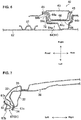
- the rear-side reinforcement portion 72 is of a curved shape such that it extends along a curve of the curved portion 68 as shown in FIG. 9 .
- the lower-side reinforcement portion 73 is, as shown in FIG. 4 , configured to have a U-shaped cross section which is opened to the right side and to form a closed-cross section cooperatively with the side sill 10. Specifically, the lower-side reinforcement portion 73 is joined to the lower-side outer wall portion 65a and the lower-side connection wall portion 65c such that this portion 73 extends beyond or straddles the ridgeline between the lower-side outer wall portion 65a and the lower-side connection wall portion 65c and thereby the closed-cross section is formed.
- the lower-side reinforcement portion 73 is provided to overlap with the upper-side side-sill flange 13 and the side-sill side wall portion 12c of the side sill 10 in the vehicle side view (i.e., when viewed from the vehicle width direction). Further, the lower-side reinforcement portion 73 is provided to overlap with the first floor cross member 17 in the vehicle side view (i.e., when viewed from the vehicle width direction).
- the door outer panel 62 determines an outer shape (contour) of the front side door 5 , when viewed from an outward side, in the vehicle width direction, of the vehicle 1 as shown in FIG. 1 .
- the rear side door 6 also comprises plural reinforcement portions similarly to the front side door 5. These reinforcement portions are provided at respective portions of a door panel portion of the rear side door 6 which overlap with the center pillar 40 and the side sill 10 in the vehicle side view (i.e., when viewed from the vehicle width direction).
- the vehicle-body structure of the vehicle 1 is required to suppress the center pillar 40 from coming into the cabin as much as possible in the vehicle side view. Further, the weight reduction of the vehicle 1 is recently required from viewpoints of the fuel economy and the like. Therefore, it is necessary to compatibly attain the further weight reduction of the vehicle and increasing of the amount of absorption of the collision load in the vehicle side collision.
- the frame members are arranged between the door inner panel 61 and the door outer panel 62 like a conventional side door, the transmission efficiency of the load may be improved. However, the weight of the vehicle improperly is increased in this case. Therefore, some structure without any frame member arranged may be required.
- FIGS. 10 - 12 show a case where a collision object A collides with the left-side part of the vehicle 1. Further, FIGS. 10 - 12 show the motion of the door panel portion 60 of the front side door 5 , omitting illustration of a motion regarding the rear side door 6.
- FIG. 11 shows a state of a portion around the side sill 10 when the collision object A comes into the cabin from the state shown in FIG. 10 .
- a load directed to a cabin inside to the right side in this figure
- the front side door 5 is moved (pushed) to the right side.
- the inner lower portion 65 comes to contact the upper-side side sill flange 13 and the side-sill side wall portion 12c of the side sill 10.
- the inner lower portion 65 transmits the collision load to the side sill 10.
- the inner lower portion 65 receives a force directed to the inside, in the surface direction, of the door inner panel 61 (to the upper side in this figure) through this coming-in of the collision object A. Meanwhile, the inner rear portion 64 transmits the collision load to the center pillar 40.
- the collision object A further comes to the right side from the state shown in FIG. 11 as shown in FIG. 12 .
- the inner lower portion 65 is suppressed from being deformed by the lower-side reinforcement portion 73.
- the lower-side reinforcement portion 73 suppresses the lower-side connection wall portion 65c from being bent (buckling deformation) to the inside, in the surface direction, of the door inner panel 61.
- the lower-side outer wall portion 65a is suppressed from being deformed to the inside, in the surface direction, of the door inner panel 61.
- the inner rear portion 64 is suppressed from being deformed by the rear-side reinforcement portion 72.
- the lower-side connection wall portion 65c provided with the rear-side reinforcement portion 72 is bent (buckling deformation) to the inside, in the surface direction, of the door inner panel 61.
- a triangular area including the inner rear portion 64 and the inner lower portion 65 is suppressed from being deformed even if it receives the collision load and the reaction load from the vehicle-body frame member 2. Consequently, it is suppressed that the door panel portion 60 is pushed into the cabin, so that a contact state of the inner rear portion 64 and the center pillar 40 and a contact state of the inner lower portion 65 and the side sill 10 are respectively maintained. Accordingly, the transmission of the collision load from the inner rear portion 64 to the center pillar 40 can be maintained, and also the transmission of the collision load from the inner lower portion 65 to the side sill 10 can be maintained.
- the collision load of the vehicle side collision is transmitted from the rear-side reinforcement portion 72 to the second floor cross member 47 by way of the center pillar 47 and the side sill 10.
- the collision load is transmitted to the upper-side part of the center pillar.
- the collision load can be dispersed to a whole part of the center pillar 40.
- the collision load can be transmitted to the roof side rail 31 by way of the center pillar 40 as well.
- the collision load of the vehicle side collision is transmitted from the lower-side reinforcement portion 73 to the first floor cross member 17 by way of the side sill 10. Since it extends in the vehicle width direction, the first floor cross member 17 can receive the collision load properly.
- the collision load of the vehicle side collision is transmitted from the front side door 5 to the vehicle-body frame member 2 , being dispersed to a whole part of the door panel portion 60 , by maintaining the contact state of the peripheral part of the door panel portion 60 and the vehicle-body frame member 2.
- the amount of absorption of the collision load can be increased.
- the collision load of the vehicle side collision is suppressed from being concentrated at the center pillar 40 , the center pillar 40 can be suppressed from coming into the cabin as much as possible.
- the vehicle-body frame member 2 comprises the side sill 10
- the front side door 5 comprises the door panel portion 60 and the reinforcement portions 72 , 73 provided at the peripheral part of the door panel portion 60 such that the reinforcement portions 72 , 73 overlap with the vehicle-body frame member 2 in the vehicle side view (i.e., when viewed from the vehicle width direction)
- the peripheral part of the door panel portion 60 comprises the inner lower portion 65 which overlaps with the side sill 10 in the vehicle side view
- the reinforcement portions 72 , 73 are provided at the inner rear portion 64 and the inner lower portion 65 of the peripheral part of the door panel portion 60.
- the triangular area including the inner rear portion 64 and the inner lower portion 65 is suppressed from being deformed.
- the deformation of the door panel portion 60 is suppressed in the above-described triangular area, it is suppressed that the door panel portion 60 is pushed into the cabin. Accordingly, the contact state of the door panel portion 60 and the vehicle-body frame member 2 is maintained. Consequently, the collision load of the vehicle side collision is transmitted from the front side door 5 to the vehicle-body frame member 2 , being dispersed to a whole part of the door panel portion 60. Accordingly, the weight reduction of the vehicle 1 and increasing of the amount of absorption of the collision load in the vehicle side collision can be compatibly attained.
- the collision object A often collides with an area of the vehicle including the center pillar 40. Therefore, according to the present embodiment where the rear-side reinforcement portion 72 is provided at the inner rear portion 64 , the deformation of the inner rear portion 64 in the vehicle side collision is suppressed. Thereby, the collision load can be received by the inner rear portion 64 and the inner lower portion 65 and transmitted to the vehicle-body frame member 2. Accordingly, even if the collision object A collides with the area of the vehicle including the center pillar 40 , the collision load is suppressed from being concentrated at the center pillar 40. Thereby, the amount of absorption of the collision load in the vehicle side collision can be further increased.
- the vehicle-body frame member 2 comprises the first floor cross member 17 provided at the position which overlaps with the side sill 10 in the vehicle side view (i.e., when viewed from the vehicle width direction) and extending in the vehicle width direction, and the lower-side reinforcement portion 73 is configured to overlap with the first floor cross member 17 in the vehicle side view (i.e., when viewed from the vehicle width direction).
- the lower-side reinforcement 73 is configured to overlap with the first floor cross member 17 in the vehicle side view, the collision load of the vehicle side collision can be effectively transmitted to the vehicle-body frame member 2. Consequently, the amount of absorption of the collision load in the vehicle side collision can be further increased.
- the inner rear portion 64 overlaps with the central part, in the vertical direction, of the center pillar 40
- the rear-side reinforcement portion 72 extends so as to include the position of the inner rear portion 64 which overlaps with the central part, in the vertical direction, of the center pillar 40.
- the front side door 5 further comprises the first impact bar 81 attached to the door panel portion 60 and extending in the vehicle longitudinal direction
- the rear-side reinforcement portion 72 is configured to include an attachment portion of the first impact bar 81 to the door panel portion 60. Since the first impact bar 81 is provided, the collision load can be absorbed by deformation of the first impact bar 81 in the vehicle side collision. Meanwhile, the collision load tends to be concentrated at the attachment portion of the first impact bar 81 to the door panel portion 60. Therefore, by configuring the reinforcement portion to include the attachment portion of the first impact bar 81 to the door panel portion 60 , deformation of the attachment portion can be suppressed even if the collision load is concentrated at the attachment portion. Thereby, the amount of absorption of the collision load in the vehicle side collision can be more further increased.
- the other embodiment is different from the above-described embodiment in the position where the reinforcement portions are attached. Specifically, in the other embodiment, the rear-side reinforcement portion 72 is not provided at the inner rear portion 64 , but a front-side reinforcement portion 271 is provided at the inner front portion 63.
- the front-side reinforcement portion 271 is a patch member which is attached along the front-side outer wall portion 63a , the front-side inner wall portion 63b , and the front-side connection wall portion 63c as shown in FIG. 13 . That is, the front-side reinforcement portion 271 is provided to extend beyond or straddle a ridgeline between the front-side outer wall portion 63a and the front-side connection wall portion 63c.
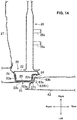
- the front-side reinforcement portion 271 is, as shown in FIG. 14 , provided to overlap with the hinge-pillar side wall portion 23c of the hinge pillar 20 in the vehicle side view (i.e., when viewed from the vehicle width direction). Further, the front-side reinforcement portion 271 is provided to overlap with the instrument-panel member 26 in the vehicle side view (i.e., when viewed from the vehicle width direction).
- the front-side reinforcement portion 271 is, as shown in FIG. 13 , provided to overlap with an upper-side end portion of the first impact bar 81 in the vehicle side view (i.e., when viewed from the vehicle width direction).
- the front-side reinforcement portion 271 is welded to the inner front portion 63 at a joint position of the first impact bar 81 to the door inner panel 61 in a state where the front-side reinforcement portion 271 overlaps between the first impact bar 81 and the inner front portion 63 (specifically, the front-side outer wall portion 63a ), which is not illustrated.
- the inner front portion 63 and the rear-side hinge-pillar flange 24 of the hinge pillar 20 come to contact each other.
- the inner front portion 63 transmits the collision load to the hinge pillar 20 and also receives the reaction load from the hinge pillar 20. Since it is reinforced by the front-side reinforcement portion 271 , the inner front portion 63 is suppressed from being deformed even if the collision load and the above-described reaction load are inputted.
- the front-side connection wall portion 63c is bent to the inside, in the surface direction, of the door inner panel 61 , i.e., buckling deformation.
- the front-side outer wall portion 63a is suppressed from being bent to the inside, in the surface direction, of the door inner panel 61.
- the lower-side outer wall portion 65a of the inner lower portion 65 is suppressed from being bent to the inside, in the surface direction, of the door inner panel 61 similarly to the above-described embodiment.
- a triangular area including the inner front portion 63 and the inner lower portion 65 is suppressed from being deformed even if it receives the collision load and the reaction load from the vehicle-body frame member 2.
- the collision load of the vehicle side collision is transmitted from the front side door 5 to the vehicle-body frame member 2 , being dispersed to a whole part of the door panel portion 60. Accordingly, the weight reduction of the vehicle 1 and increasing of the amount of absorption of the collision load in the vehicle side collision can be compatibly attained in the other embodiment as well.
- the vehicle-body frame member 2 overlaps with the hinge pillar 20 , specifically the inner frame portion 63 overlaps with the hinge pillar 20 and the instrument-panel member 26 in the vehicle side view (i.e., when viewed from the vehicle width direction).
- the front-side reinforcement portion 271 overlaps with the instrument-panel member 26 in the vehicle side view (i.e., when viewed from the vehicle width direction).
- a portion of the hinge pillar 20 which overlaps with the instrument-panel member 26 has high rigidity against the collision load applied from the vehicle side.
- the front-side reinforcement portion 271 is configured to overlap with the instrument-panel member 26 in the vehicle side view (i.e., when viewed from the vehicle width direction), the collision load of the vehicle side collision can be effectively transmitted to the vehicle-body frame member 2. Consequently, the amount of absorption of the collision load in the vehicle side collision can be more further increased.
- the reinforcement portions 72 , 73 , 271 are provided at the door inner panel 61 in the above-described embodiments, these may be provided at the peripheral part of the door outer panel 62. In this case, the deformation of the door outer panel 62 in the vehicle side collision is so suppressed that it is suppressed that the side door is pushed into the cabin, so that the connection state of the door panel portion 60 and the vehicle-body frame member 2 is maintained.
- an engagement state of the door panel portion 60 and the vehicle-body frame member 2 may be maintained by providing catcher pins as the reinforcement portions 72 , 73 , 271 .
- the door inner panel 61 (the inner lower portion 65 ) forms the closed-cross section together with only the lower-side reinforcement portion 73 in the above-described embodiments
- the rear-side reinforcement portion 72 and the front-side reinforcement portion 271 may respectively form a closed-cross section together with the door inner panel 61 similarly to the lower-side reinforcement portion 73.
- the lower-side reinforcement portion 73 may be a patch member attached along the lower-side outer wall portion 65a , the lower-side inner wall portion 65b , and the lower-side connection wall portion 65c , similarly to the rear-side reinforcement portion 72 and so on.
- the rear-side reinforcement portion 72 and the lower-side reinforcement portion 73 may be configured to be continuous in the above-described embodiment.
- the lower-side reinforcement portion 73 and the front-side reinforcement portion 271 may be configured to be continuous in the above-described other embodiment.
- a part or a whole part of the reinforcement portions 72 , 73 , 271 may not be configured to be a separate member from the door inner panel 61.
- the reinforcement portions 72 , 73 , 271 can be configured by making the plate thickness of a portion of the door inner panel 61 which corresponds to the reinforcement portions 72 , 73 , 271 thicker than the other part of the door inner panel 61 , for example.
Abstract
Description
- The present invention relates to a vehicle-body structure of a vehicle, and a vehicle.
- Conventionally, in a vehicle which comprises a frame member forming an opening portion for entrance at a vehicle side part and a side door provided so as to open and close the opening portion, a structure of the side door to cope with a vehicle side collision has been developed (see Japanese Patent Laid-Open Publication No.
2018-52138 - The above-described patent document discloses a door for a vehicle which is provided with panel portions which are arranged on a cabin inward side and on a cabin outward side, a frame portion which is arranged between the panel portions, and a reinforcement portion which is arranged at the frame portion, wherein the frame portion comprises front and rear parts which respectively extend in a vertical direction at front-side and rear-side portions of the panel portions and a lower part which interconnects respective lower portions of the front and rear parts, and the reinforcement portion comprises a first reinforcement which interconnects the above-described front and rear parts and a second reinforcement which interconnects the first reinforcement and the above-described lower part.
- Herein, a vehicle-body structure of the vehicle is required to suppress a center pillar from coming into a cabin as much as possible in the vehicle side collision. Recently, weight reduction of the vehicle (light-weight vehicle) is also required from viewpoints of the fuel economy and the like. Therefore, it is necessary to compatibly attain the further weight reduction of the vehicle and increasing of the amount of absorption of the collision load (the collision-load absorption performance) in the vehicle side collision. In the door disclosed in the above-described patent document, however, since it is necessary to provide both the frame portion and the reinforcement portion, the weight is so increased that it may be difficult to satisfy the above-described requirements.
- The present invention has been devised in view of the above-described matter, and an object of the present invention is to compatibly attain the weight reduction of the vehicle and increasing of the amount of absorption of the collision load in the vehicle side collision.
- The present invention is a vehicle-body structure of a vehicle, comprising a vehicle-body frame member forming an opening portion for entrance at a vehicle side part, and a side door provided so as to open and/or close the opening portion, wherein the vehicle-body frame member comprises a side sill, the side door comprises a door panel portion and a reinforcement portion provided at a peripheral part of the door panel portion such that the reinforcement portion overlaps with the vehicle-body frame member in a vehicle side view, the peripheral part of the door panel portion comprises a lower-side overlapping portion which overlaps with the side sill in the vehicle side view, and the reinforcement portion is provided at two side-portions of the peripheral part of the door panel portion which are continuous and include the lower-side overlapping portion.
- That is, in the vehicle side collision, the side door is moved (pushed) toward the cabin and comes to contact the vehicle-body frame member. At this moment, the door panel portion receives a reaction load from the vehicle-body frame member in addition to the collision load. According to the present invention, deformation of the two side-portions of the peripheral part of the door panel portion which are continuous and include the lower-side overlapping portion where the reinforcement portions are provided is suppressed. Thereby, deformation of a triangular area including the above-described two side-portions is suppressed even if it receives the collision load and the reaction load from the vehicle-body frame member. Thus, since the deformation of the door panel portion is suppressed in the triangular area including the two side-portions, the door panel portion is suppressed from coming into the cabin. Accordingly, contact state of the door panel portion and the vehicle-body frame member is maintained. Consequently, the collision load of the vehicle side collision is transmitted from the side door to the vehicle-body frame member, being dispersed to a whole part of the door panel portion. Accordingly, the weight reduction of the vehicle and increasing of the amount of absorption of the collision load in the vehicle side collision can be compatibly attained.
- In an embodiment of the present invention, the vehicle-body frame member comprises a floor cross member provided at a position which overlaps with the side sill in the vehicle side view and extending in a vehicle width direction, and the reinforcement portion is configured to overlap with the floor cross member in the vehicle side view.
- According to this embodiment, since the floor cross member extends in the vehicle width direction, a portion of the side sill which overlaps with the floor cross member has high rigidity against the collision load applied from the vehicle side. Accordingly, if the lower-side reinforcement portion is configured to overlap with the floor cross member in the vehicle side view (i.e., when viewed from the vehicle width direction), the collision load of the vehicle side collision can be effectively transmitted to the vehicle-body frame member. Thereby, the amount of absorption of the collision load in the vehicle side collision can be further increased.
- In another embodiment of the present invention, the vehicle-body frame member comprises a center pillar. Particularly, the peripheral part of the door panel portion comprises a center overlapping portion which overlaps with the center pillar in the vehicle side view. Further particularly, the reinforcement portion is provided at the lower-side overlapping portion and the center overlapping portion of the peripheral part of the door panel portion.
- In the vehicle side collision, a collision object often collides with an area of the vehicle including the center pillar. Therefore, according to this embodiment where the reinforcement portion is provided at the center overlapping portion, deformation of the center overlapping portion in the vehicle side collision is suppressed. Thereby, the collision load can be received by the center overlapping portion and the lower-side overlapping portion and transmitted to the vehicle-body frame member. Accordingly, even if the collision object collides with the area of the vehicle including the center pillar, the collision load is suppressed from being concentrated at the center pillar. Thereby, the amount of absorption of the collision load in the vehicle side collision can be further increased.
- Further particularly, the two side-portions of the peripheral part of the door panel portion are the lower-side overlapping portion and the center overlapping portion.
- In another embodiment of the present invention, the center overlapping portion overlaps with a central part, in a vertical direction, of the center pillar, and the reinforcement portion provided at the center overlapping portion extends so as to include a position of the center overlapping portion which overlaps with the central part, in the vertical direction, of the center pillar.
- According to this embodiment, since the reinforcement portion extends so as to include the position of the center overlapping portion which overlaps with the central part, in the vertical direction, of the center pillar, the collision load of the vehicle side collision can be effectively transmitted to an upper-side part of the center pillar. Thereby, the amount of absorption of the collision load in the vehicle side collision can be more further increased.
- In another embodiment of the present invention, the vehicle-body frame member comprises a hinge pillar and an instrument-panel member provided at a position which overlaps with the hinge pillar in the vehicle side view and extending in the vehicle width direction, the peripheral part of the door panel portion comprises a front-side overlapping portion which overlaps with the hinge pillar and the instrument-panel member in the vehicle side view. Particularly, the reinforcement portion is provided at the lower-side overlapping portion and the front-side overlapping portion of the peripheral part of the door panel portion.
- According to this embodiment, since the instrument-panel member extends in the vehicle width direction, a portion of the hinge pillar which overlaps with the instrument-panel member has high rigidity against the collision load applied from the vehicle side. Accordingly, if the front-side reinforcement portion is configured to overlap with the instrument-panel member in the vehicle side view (i.e., when viewed from the vehicle width direction), the collision load of the vehicle side collision can be effectively transmitted to the vehicle-body frame member. Thereby, the amount of absorption of the collision load in the vehicle side collision can be more further increased.
- Further particularly, the two side-portions of the peripheral part of the door panel portion are the lower-side overlapping portion and the front-side overlapping portion.
- In another embodiment of the present invention, the side door further comprises an impact bar attached to the door panel portion and extending in a vehicle longitudinal direction, and the reinforcement portion is configured to include an attachment portion of the impact bar to the door panel portion.
- According to this embodiment, since the impact bar is provided, the collision load can be absorbed by deformation of the impact bar in the vehicle side collision. Meanwhile, the collision load tends to be concentrated at the attachment portion of the impact bar to the door panel portion. Therefore, by configuring the reinforcement portion to include the attachment portion of the impact bar to the door panel portion, deformation of the attachment portion can be suppressed even if the collision load is concentrated at the attachment portion. Thereby, the amount of absorption of the collision load in the vehicle side collision can be more further increased.
- Further particularly, the reinforcement portion is located at the same position, in a vehicle longitudinal direction, as a floor cross member.
- Further particularly, the side door is a front side door.
- Further particularly, the side door is a rear side door.
- Further particularly, a vehicle includes the above vehicle-body structure.
- The present invention will become apparent from the following description which refers to the accompanying drawings.
-
-
FIG. 1 is a side view showing a left-side side part of a vehicle provided with a vehicle-body structure of the vehicle according to an embodiment of the present invention, which shows around a front side door. -
FIG. 2 is a side view showing a vehicle-body frame member at the left-side side part of the vehicle. -
FIG. 3 is a side view showing a state where an outer panel of the front side door is removed, when viewed from a vehicle left side. -
FIG. 4 is a sectional view taken along line IV-IV ofFIG. 3 . -
FIG. 5 is a sectional view taken along line V-V ofFIG. 3 . -
FIG. 6 is a sectional view taken along line VI-VI ofFIG. 3 . -
FIG. 7 is a sectional view taken along line VII-VII ofFIG. 1 . -
FIG. 8 is a sectional view taken along line VIII-VIII ofFIG. 3 . -
FIG. 9 is a perspective view of a curved portion of a door inner panel, when viewed from a front left side. -
FIG. 10 is a plan view showing a state where a collision object contacts the front side door in a vehicle side collision. -
FIG. 11 is a sectional view showing a state of a portion around a side sill when the collision object comes into a cabin from the state shown inFIG. 10 . -
FIG. 12 is a sectional view showing a state of the portion around the side sill when the collision object further comes into the cabin from the state shown inFIG. 10 . -
FIG. 13 is a side view showing a state of the vehicle provided with a vehicle-body structure according to another embodiment where the outer panel of the front side door is removed, when viewed from the vehicle left side. -
FIG. 14 is a sectional view taken along line XIV-XIV ofFIG. 13 . - Hereafter, embodiments of the present invention will be described referring to the drawings. In the following description, front, rear, left, right, upper and lower which respectively mean directions relative to a vehicle 1 will be simply referred to as "front," "rear," "left," "right," "upper," and "lower."
-
FIG. 1 shows a left-side side part of the vehicle 1 to which a vehicle-body structure according to an embodiment is applied. The vehicle 1 is particularly a 4-door type of passenger car. In the present embodiment, since the vehicle-body structure of the vehicle 1 is configured to be laterally symmetrical, the vehicle-body structure of the left-side part of the vehicle 1 will be described specifically only, and detailed explanation of the one of a right-side part of the vehicle 1 will be omitted. Further, in the following description, there is a case where an inward side, in a vehicle width direction, of the vehicle 1 will be simply referred to as "right side" and also an outward side, in the vehicle width direction, of the vehicle 1 will be simply referred to as "left side." - The vehicle 1 comprises a vehicle-
body frame member 2 which forms front-side and rear-side opening portions forentrance side opening portion 3 so as to open and close thisopening portion 3. A rear side door 6 is arranged at the rear-side opening portion 4 so as to open and close thisopening portion 4. - The vehicle-
body frame member 2 particularly comprises, as shown inFIG. 2 , aside sill 10 which is arranged at a lower part of the vehicle 1 and extends in a longitudinal direction, ahinge pillar 20 which extends upwardly from a front-side end portion of theside sill 10, afront pillar 30 which extends obliquely rearwardly-and-upwardly from an upper-side end portion of thehinge pillar 20, and aroof side rail 31 which continuously extends rearwardly from a rear-side end portion of thefront pillar 30. The vehicle-body frame member 2 further comprises acenter pillar 40 which extends in a vertical direction and interconnects a central part, in the longitudinal direction, of theside sill 10 and a central part, in the longitudinal direction, of theroof side rail 31. The front-side opening portion 3 is partitioned by theside sill 10, thehinge pillar 20, thefront pillar 30, theroof side rail 31, and thecenter pillar 40. - Further, the vehicle-
body frame member 2 particularly comprises awheel arch 50 which extends upwardly-and-rearwardly in an arch shape from a rear-side end portion of theside sill 10 and forms a part of a wheel house and aquarter pillar 51 which extends vertically and interconnects thewheel arch 50 and theroof side rail 31. The rear-side opening portion 4 is partitioned by theside sill 10, theroof side rail 31, thecenter pillar 40, thewheel arch 50, and thequarter pillar 51. - The side sill 10 particularly comprises, as shown in
FIG. 4 , a side-sillinner panel 11 which is positioned on the inward side, in the vehicle width direction, of the vehicle 1 (on the right side in this figure) and has a hat-shaped cross section and a side-sillouter panel 12 which is positioned on the outward side, in the vehicle width direction, of the vehicle 1 (on the left side in this figure) and has a hat-shaped cross section. The cross section of the side-sillinner panel 11 is opened to the left side, and the cross section of the side-sillouter panel 12 is opened to the right side. Each of the side-sillinner panel 11 and the side-sillouter panel 12 has side-sill flanges 13 which extend in the vertical direction and in the longitudinal direction at its upper-side end portion and its lower-side end portion. The respective side-sill flanges 13 overlap with each other in the vehicle width direction and are welded together. Thus, a closed-cross section is formed by the side-sillinner panel 11 and the side-sillouter panel 12. - The side-sill
outer panel 12 particularly comprises, as shown inFIG. 4 , a side-sillupper wall portion 12a which extends toward the left side from a lower-side end portion of the upper-side side-sill flange 13, a side-silllower wall portion 12b which extends, facing the side-sillupper wall portion 12a in the vertical direction, and a side-sillside wall portion 12c which interconnects a left-side end portion of the side-sillupper wall portion 12a and a left-side end portion of the side-silllower wall portion 12b in the vertical direction. - A first side-
sill reinforcement 14 and a second side-sill reinforcement 15 are provided inside theside sill 10. The first side-sill reinforcement 14 is configured to have a hat-shaped cross section which is opened to the right side, and arranged along the side-sillouter panel 12. The second side-sill reinforcement 15 is of a flat plate shape. Respective end portion, in the vertical direction, of the first side-sill reinforcement 14 overlap with the respective side-sill flanges 13 in the vehicle width direction and are welded together with the side-sill flanges 13. The second side-sill reinforcement 15 is welded to a right side of the first side-sill reinforcement 14. - As shown in
FIG. 4 , a left-side end portion of afloor panel 16 which expands in the longitudinal direction and in the vehicle width direction is joined to a lower-side portion of the side-sillinner panel 11. Further, a left-side end portion of a firstfloor cross member 17 which extends in the vehicle width direction is joined to an upper-side portion of the side-sillinner panel 11. Afloor side rail 18 which extends in the longitudinal direction is joined to a lower face of thefloor panel 16. - The
hinge pillar 20 comprises one or more, particularly two front-door hinges 21 to support the front side door 5. The two front-door hinges 21 are provided to be spaced apart from each other in the vertical direction. - The
hinge pillar 20 particularly comprises, as shown inFIG. 5 , a hinge-pillarinner panel 22 which is positioned on the inward side, in the vehicle width direction, of the vehicle 1 (on the right side in this figure) and has a hat-shaped cross section and a hinge-pillarouter panel 23 which is positioned on the outward side, in the vehicle width direction, of the vehicle 1 (on the left side in this figure) and has a hat-shaped cross section. The cross section of the hinge-pillarinner panel 22 is opened to the left side, and the cross section of the hinge-pillarouter panel 23 is opened to the right side. Each of the hinge-pillarinner panel 22 and the hinge-pillarouter panel 23 has hinge-pillar flanges 24 which extend in the vertical direction and in the longitudinal direction at its front-side end portion and its rear-side end portion. The respective hinge-pillar flanges 24 overlap with each other in the vehicle width direction and are welded together. Thus, a closed-cross section is formed by the hinge-pillarinner panel 22 and the hinge-pillarouter panel 23. - The hinge-pillar
outer panel 23 particularly comprises, as shown inFIG. 5 , a hinge-pillarfront wall portion 23a which extends toward the left side from a rear-side end portion of the upper-side hinge-pillar flange 24, a hinge-pillarrear wall portion 23b which extends, facing the hinge-pillarfront wall portion 23a in the longitudinal direction, and a hinge-pillarside wall portion 23c which interconnects a left-side end portion of the hinge-pillarfront wall portion 23a and a left-side end portion of the hinge-pillarrear wall portion 23b in the longitudinal direction. - A hinge-
pillar reinforcement 25 is particularly provided inside thehinge pillar 20. The hinge-pillar reinforcement 25 is configured to have a hat-shaped cross section which is opened to the right side, and arranged along the hinge-pillarouter panel 23. Respective end portions, in the longitudinal direction, of the hinge-pillar reinforcement 25 overlap with the respective hinge-pillar flanges 24 in the vehicle width direction and are welded together with the hinge-pillar flanges 24. Herein, inFIG. 5 , the front-side end portion of the hinge-pillar reinforcement 25 does not overlap with the hinge-pillar flange 24. At another part of the hinge-pillar reinforcement 25, however, the front-side end portion of the hinge-pillar reinforcement 25 overlaps with the hinge-pillar flanges 24 as well. - As shown in
FIG. 5 , a left-side end portion of an instrument-panel member 26 is particularly joined to the hinge-pillarinner panel 22. The instrument-panel member 26 is provided withhinges 26a to pivotably support a glove box in the vertical direction and others. Adash panel 27 which partitions a cabin from an engine room is joined to a front-side end portion of the hinge-pillarinner panel 22. - The
center pillar 40 is provided with one or more, particularly two rear-door hinges 41 to support the openable rear side door 6. The two rear-door hinges 41 are provided to be spaced apart from each other in the vertical direction. Thecenter pillar 40 is further provided with astriker 42 at its front-side position which is located slightly below the upper-side rear-door hinge 41. Thestriker 42 is fixed to thecenter pillar 40. Thestriker 42 is a member to lock the front side door 5 in a closed state through its engagement with adoor latch 5b of the front side door 5 (seeFIG. 3 ). - The
center pillar 40 particularly comprises, as shown inFIG. 6 , a center-pillarinner panel 43 which is positioned on the inward side, in the vehicle width direction, of the vehicle 1 (on the right side in this figure) and has a hat-shaped cross section and a center-pillarouter panel 44 which is positioned on the outward side, in the vehicle width direction, of the vehicle 1 (on the left side in this figure) and has a hat-shaped cross section. The cross section of the center-pillarinner panel 43 is opened to the left side, and the cross section of the center-pillarouter panel 44 is opened to the right side. Each of the center-pillarinner panel 43 and the center-pillarouter panel 44 has center-pillar flanges 45 which extend in the vertical direction and in the longitudinal direction at its front-side end portion and its rear-side end portion. The respective center-pillar flanges 45 overlap with each other in the vehicle width direction and are welded together. Thus, a closed-cross section is formed by the center-pillarinner panel 43 and the center-pillarouter panel 44. - The center-pillar
outer panel 44 particularly comprises, as shown inFIG. 6 , a center-pillarfront wall portion 44a which extends toward the left side from a rear-side end portion of the front-side center-pillar flange 45, a center-pillarrear wall portion 44b which extends, facing the center-pillarfront wall portion 44a in the longitudinal direction, and a center-pillarside wall portion 44c which interconnects a left-side end portion of the center-pillarfront wall portion 44a and a left-side end portion of the center-pillarrear wall portion 44b in the longitudinal direction. - A center-
pillar reinforcement 46 is provided inside thecenter pillar 40. The center-pillar reinforcement 46 is configured to have a hat-shaped cross section which is opened to the right side, and arranged along the center-pillarouter panel 44. Respective end portion, in the longitudinal direction, of the center-pillar reinforcement 46 overlap with the respective center-pillar flanges 45 in the vehicle width direction and are welded together with the center-pillar flanges 45. - As shown in
FIG. 2 , a lower-side end portion of thecenter pillar 40 is located at the same position as a secondfloor cross member 47 which extends in the vehicle width direction. - The
roof side rail 31 particularly comprises, as shown inFIG. 7 , a roof-sideinner panel 32 which is positioned on the inward side, in the vehicle width direction, of the vehicle 1 (on the right side in this figure) and a roof-sideouter panel 33 which is positioned on the outward side, in the vehicle width direction, of the vehicle 1 (on the left side in this figure) and has a C-shaped cross section. The cross section of the roof-sideouter panel 33 is opened to the right side. The roof-sideouter panel 33 has a roof-side flange 34 which extends in the vertical direction and in the longitudinal direction at its lower-side end portion. The roof-side flange 34 overlaps with a lower-side end portion of the roof-sideinner panel 32 in the vehicle width direction and these are welded together. An upper-side end portion of the roof-sideouter panel 33 overlaps with an upper-side end portion of the roof-sideinner panel 32 in the vehicle width direction and these are welded together. Thus, a closed-cross section is formed by the roof-sideinner panel 32 and the roof-sideouter panel 33. - A roof-
side reinforcement 35 is particularly provided inside theroof side rail 31. The roof-side reinforcement 35 is configured to have a hat-shaped cross section which is opened to the right side, and arranged along the roof-sideouter panel 33. A lower-side end portion of the roof-side reinforcement 35 overlaps with a lower-side end portion of the roof-sideinner panel 32 and the roof-side flange 34 of the roof-sideouter panel 33 in the vehicle width direction and these are welded together. Meanwhile, an upper-side end portion of the roof-side reinforcement 35 overlaps with an upper-side end portion of the roof-sideinner panel 32 and an upper-side end portion of the roof-sideouter panel 33 in the vehicle width direction and these are welded together. - As shown in
FIG. 7 , aroof cross member 36 which extends in the vehicle width direction is particularly provided on the right side of theroof side rail 31. A left-side end portion of theroof cross member 36 is joined to theroof side rail 31. - Next, the front side door 5 will be described as an example of a side-door structure. In the following description, a state where the front side door 5 closes the front-
side opening portion 3 is a premise. Herein, while detailed description of the rear side door 6 is omitted, the rear side door 6 has substantially the same structure as the front side door 5 except a shape of adoor panel portion 60 and a shape of a reinforcement portion, which will be described later. - The front side door 5 comprises, as shown in
FIGS. 4 - 8 , thedoor panel portion 60 which has a doorinner panel 61 which is positioned on the inward side, in the vehicle width direction, of the vehicle (on the right side in this figure) and a doorouter panel 62 which is positioned on the outward side, in the vehicle width direction, of the vehicle (on the left side in this figure). The doorinner panel 61 and the doorouter panel 62 are welded together so as to have a closed-cross section formed thereby. A door trim is joined to a face of the doorinner panel 61 which is opposite to the doorouter panel 62. - The door
inner panel 61 is particularly made of a single-sheet steel plate. The doorinner panel 61 is formed along a periphery of the front-side opening portion 3 as shown inFIG. 3 . The doorinner panel 61 particularly comprises at least any one of aninner front portion 63 which extends in the vertical direction along thehinge pillar 20, an innerrear portion 64 which extends in the vertical direction along a lower part of thecenter pillar 40, and an innerlower portion 65 which extends along theside sill 10 and interconnects a lower-side end portion of theinner front portion 63 and a lower-side end portion of the innerrear portion 64. The doorinner panel 61 further comprises abeltline portion 66 which extends straightly in the longitudinal direction and interconnects an upper-side end portion of theinner front portion 63 and an upper-side end portion of the innerrear portion 64. The doorinner panel 61 further comprises awindow frame portion 67 which forms a quarter-window opening portion which is closed with a window glass. A corner portion between the innerrear portion 64 and the innerlower portion 65 of the doorinner panel 61 is configured as acurved portion 68 which is curved smoothly from the innerrear portion 64 toward the innerlower portion 65. - The
inner front portion 63 particularly comprises, as shown inFIG. 5 , a front-sideouter wall portion 63a which is positioned at the outside, in a surface direction, of the door inner panel 61 (on the front side in this figure), a front-sideinner wall portion 63b which is positioned on the inside, in the surface direction, (on the rear side in this figure) of the front-sideouter wall portion 63a, and a front-sideconnection wall portion 63c which interconnects the front-sideouter wall portion 63a and the front-sideinner wall portion 63b in the vehicle width direction. The front-sideouter wall portion 63a comprises a part which expands in the longitudinal direction and in the vertical direction and another part which expands in the vehicle width direction and in the vertical direction continuously from a front-side end portion of the above-described part. The front-sideinner wall portion 63b expands in the longitudinal direction and in the vertical direction. The front-sideconnection wall portion 63c expands in the vehicle width direction and in the vertical direction so as to interconnect a rear-side end portion of the front-sideouter wall portion 63a and a front-side end portion of the front-sideinner wall portion 63b. The front-sideouter wall portion 63a extends in the vertical direction such that thisportion 63a overlaps with the rear-side hinge-pillar flange 24 and the hinge-pillarside wall portion 23c of thehinge pillar 20 in the vehicle side view (i.e., when viewed from the vehicle width direction). The front-sideinner wall portion 63b extends in the vertical direction such that thisportion 63b overlaps with the rear-side hinge-pillar flange 24 of thehinge pillar 20 in the vehicle side view (i.e., when viewed from the vehicle width direction). Theinner front portion 63 forms a front-side overlapping portion which overlaps with thehinge pillar 20 in the vehicle side view. - The inner
rear portion 64 particularly comprises, as shown inFIG. 6 , a rear-sideouter wall portion 64a which is positioned at the outside, in a surface direction, of the door inner panel 61 (on the rear side in this figure), a rear-sideinner wall portion 64b which is positioned on the inside, in the surface direction, (on the front side in this figure) of the rear-sideouter wall portion 64a, and a rear-sideconnection wall portion 64c which interconnects the rear-sideouter wall portion 64a and the rear-sideinner wall portion 64b in the vehicle width direction. The rear-sideouter wall portion 64a comprises a part which extends or expands in the longitudinal direction and in the vertical direction and another part which expands in the vehicle width direction and in the vertical direction continuously from a rear-side end portion of the above-described part. The rear-sideinner wall portion 64b extends or expands in the longitudinal direction and in the vertical direction. The rear-sideconnection wall portion 64c expands in the vehicle width direction and in the vertical direction so as to interconnect a front-side end portion of the rear-sideouter wall portion 64a and a rear-side end portion of the rear-sideinner wall portion 64b. A ridgeline is formed between the rear-sideconnection wall portion 64c and the rear-sideouter wall portion 64a. The rear-sideouter wall portion 64a extends in the vertical direction such that thisportion 64a overlaps with the front-side center-pillar flange 45 and the center-pillarside wall portion 44c of thecenter pillar 40 in the vehicle side view (i.e., when viewed from the vehicle width direction). The rear-sideinner wall portion 64b extends in the vertical direction such that thisportion 64b overlaps with the front-side center-pillar flange 45 of thecenter pillar 40 in the vehicle side view (i.e., when viewed from the vehicle width direction). - The inner
rear portion 64 is particularly configured to overlap with the central part, in the vertical direction, of thecenter pillar 40 in the vehicle side view (i.e., when viewed from the vehicle width direction). The innerrear portion 64 forms a center overlapping portion which overlaps with thecenter pillar 40 in the vehicle side view. - The
door latch 5b engaging with thestriker 42 is provided at a part of the innerrear portion 64 which corresponds to thestriker 42. Thedoor latch 5b is provided at a position of the innerrear portion 64 which overlaps with the central part, in the vertical direction, of thecenter pillar 40. Thedoor latch 5b causes the front side door 5 to engage with thecenter pillar 40 through its engagement with thestriker 42. Thedoor latch 5b is configured to control an engagement state with thestriker 42 by operating adoor handle 5a (seeFIG. 1 ). - The inner
lower portion 65 particularly comprises, as shown inFIG. 4 , a lower-sideouter wall portion 65a which is positioned at the outside, in the surface direction, of the door inner panel 61 (on the lower side in this figure), a lower-sideinner wall portion 65b which is positioned on the inside, in the surface direction, (on the upper side in this figure) of the lower-sideouter wall portion 65a, and a lower-sideconnection wall portion 65c which interconnects the lower-sideouter wall portion 65a and the lower-sideinner wall portion 65b in the vehicle width direction. The lower-sideouter wall portion 65a and the lower-sideinner wall portion 65b extend or expand in the longitudinal direction and in the vertical direction. The lower-sideconnection wall portion 65c extends or expands in the vehicle width direction and in the longitudinal direction so as to interconnect an upper-side end portion of the lower-sideouter wall portion 65a and a lower-side end portion of the lower-sideinner wall portion 65b. A ridgeline is formed between the lower-sideconnection wall portion 65c and the lower-sideouter wall portion 65a. The lower-sideouter wall portion 65a extends in the longitudinal direction such that thisportion 65a overlaps with the upper-side side-sill flange 13 and the side-sillside wall portion 12c of theside sill 10 in the vehicle side view (i.e., when viewed from the vehicle width direction). The lower-sideinner wall portion 65b extends in the longitudinal direction such that thisportion 65b overlaps with the upper-side side-sill flange 13 of theside sill 10 in the vehicle side view (i.e., when viewed from the vehicle width direction). The innerlower portion 65 forms a lower-side overlapping portion which overlaps with theside sill 10 in the vehicle side view. - The
window frame portion 67 comprises, as shown inFIG. 7 , an upper-sideouter wall portion 67a which is positioned at the outside, in the surface direction, of the door inner panel 61 (on the upper side in this figure), an upper-sideinner wall portion 67b which is positioned on the inside, in the surface direction, (on the lower side in this figure) of the upper-sideouter wall portion 67a, and an upper-sideconnection wall portion 67c which interconnects the upper-sideouter wall portion 67a and the upper-sideinner wall portion 67b in the vertical direction and in the vehicle width direction. The upper-sideouter wall portion 67a expands in the longitudinal direction and in the vehicle width direction and slants downwardly toward the right side. The upper-sideinner wall portion 67b expands in the longitudinal direction and in the vertical direction. The lower-sideconnection wall portion 65c is curved downwardly toward the left side from a right-side end portion of the upper-sideouter wall portion 67a so as to interconnect a right-side end portion of the upper-sideouter wall portion 67a and an upper-side end portion of the upper-sideinner wall portion 67b. The upper-sideouter wall portion 67a and the upper-side connection portion 67c extend such that they overlap with the roof-side flange 34 in the vehicle sideview (i.e., when viewed from the vehicle width direction). - As shown in
FIG. 3 , afirst impact bar 81 and asecond impact bar 82 are attached to the doorinner panel 61. Thefirst impact bar 81 extends obliquely rearwardly-and-downwardly and interconnects an upper-side end portion of theinner front portion 63 and a lower-side end portion of the innerrear portion 64. Thesecond impact bar 82 extends obliquely rearwardly-and-downwardly so as to interconnect a middle part, in the longitudinal direction, of thebeltline portion 66 and a middle part, in the vertical direction, of the innerrear portion 64. Thefirst impact bar 81 is configured such that both-side end portions, in the longitudinal direction, thereof have a hat-shaped cross section and a middle portion, in the longitudinal direction, thereof has an M-shaped cross section as shown inFIGS. 4 and6 . - As shown in
FIGS. 3 - 8 , plural reinforcement portions are provided at a peripheral portion of the doorinner panel 61. Specifically, the reinforcement portions are provided at two side-portions of the peripheral part of thedoor panel portion 60 which are continuous and include the innerlower portion 65. More specifically, the reinforcement portions comprise a rear-side reinforcement portion 72 which is provided along the innerrear portion 64 and a lower-side reinforcement portion 73 which is provided along the innerlower portion 65. Thereinforcement portions - The rear-
side reinforcement portion 72 is a patch member which is attached along the rear-sideouter wall portion 64 and the rear-sideconnection wall portion 64c as shown inFIG. 3 . That is, the rear-side reinforcement portion 72 is provided to extend beyond or straddle a ridgeline between the rear-sideouter wall portion 64a and the rear-sideconnection wall portion 64c. The rear-side reinforcement portion 72 is, as shown inFIG. 5 , provided to overlap with the front-side center-pillar flange 45 and the center-pillarside wall portion 44c of thecenter pillar 40 in the vehicle side view (i.e., when viewed from the vehicle width direction). Further, the rear-side reinforcement portion 72 is located at the same position, in the longitudinal direction, as the secondfloor cross member 47. - The rear-
side reinforcement portion 72 is, as shown inFIGS. 3 and8 , provided to overlap with a lower-side end portion of thefirst impact bar 81 in the vehicle side view (i.e., when viewed from the vehicle width direction). The rear-side reinforcement portion 72 is welded to the innerrear portion 64 in a state where thisportion 72 overlaps with thefirst impact bar 81 and the inner rear portion 64 (specifically, the rear-sideouter wall portion 64a) at a joint position of thefirst impact bar 81 to the doorinner panel 61, which is not illustrated. - The rear-
side reinforcement portion 72 extends, as shown inFIG. 3 , so as to include a position of the innerrear portion 64 which overlaps with the central part, in the vertical direction, of thecenter pillar 40. Specifically, it extends up to a position of an upper-side end portion of thedoor latch 5b in the present embodiment. - The rear-
side reinforcement portion 72 is of a curved shape such that it extends along a curve of thecurved portion 68 as shown inFIG. 9 . - The lower-
side reinforcement portion 73 is, as shown inFIG. 4 , configured to have a U-shaped cross section which is opened to the right side and to form a closed-cross section cooperatively with theside sill 10. Specifically, the lower-side reinforcement portion 73 is joined to the lower-sideouter wall portion 65a and the lower-sideconnection wall portion 65c such that thisportion 73 extends beyond or straddles the ridgeline between the lower-sideouter wall portion 65a and the lower-sideconnection wall portion 65c and thereby the closed-cross section is formed. The lower-side reinforcement portion 73 is provided to overlap with the upper-side side-sill flange 13 and the side-sillside wall portion 12c of theside sill 10 in the vehicle side view (i.e., when viewed from the vehicle width direction). Further, the lower-side reinforcement portion 73 is provided to overlap with the firstfloor cross member 17 in the vehicle side view (i.e., when viewed from the vehicle width direction). - The door
outer panel 62 determines an outer shape (contour) of the front side door 5, when viewed from an outward side, in the vehicle width direction, of the vehicle 1 as shown inFIG. 1 . - Herein, the rear side door 6 also comprises plural reinforcement portions similarly to the front side door 5. These reinforcement portions are provided at respective portions of a door panel portion of the rear side door 6 which overlap with the
center pillar 40 and theside sill 10 in the vehicle side view (i.e., when viewed from the vehicle width direction). - Herein, the vehicle-body structure of the vehicle 1 is required to suppress the
center pillar 40 from coming into the cabin as much as possible in the vehicle side view. Further, the weight reduction of the vehicle 1 is recently required from viewpoints of the fuel economy and the like. Therefore, it is necessary to compatibly attain the further weight reduction of the vehicle and increasing of the amount of absorption of the collision load in the vehicle side collision. - If the frame members are arranged between the door
inner panel 61 and the doorouter panel 62 like a conventional side door, the transmission efficiency of the load may be improved. However, the weight of the vehicle improperly is increased in this case. Therefore, some structure without any frame member arranged may be required. - Herein, according to the present embodiment of the invention, buckling deformation of the door
inner panel 61 is so suppressed in the vehicle side collision by providing the rear-side reinforcement portion 72 and the lower-side reinforcements 73 at the doorinner panel 61 as described above that the collision load can be efficiently transmitted to the vehicle-body frame member 2. Hereafter, a motion of thedoor panel portion 60 in the vehicle side collision will be described referring toFIGS. 10 - 12 . Herein,FIGS. 10 - 12 show a case where a collision object A collides with the left-side part of the vehicle 1. Further,FIGS. 10 - 12 show the motion of thedoor panel portion 60 of the front side door 5, omitting illustration of a motion regarding the rear side door 6. - A situation where the collision object A moves toward the
center pillar 40 and then comes to contact the left-side part of the vehicle 1 as shown inFIG. 10 is assumed here. Herein, the innerrear portion 64 is in a state where it is interposed between thecenter pillar 40 and the collision object A. -
FIG. 11 shows a state of a portion around theside sill 10 when the collision object A comes into the cabin from the state shown inFIG. 10 . When the collision object A comes in as shown inFIG. 11 from the state shown inFIG. 10 , a load directed to a cabin inside (to the right side in this figure) is inputted (applied). Herein, the front side door 5 is moved (pushed) to the right side. Thereby, as show inFIG. 11 , the innerlower portion 65 comes to contact the upper-sideside sill flange 13 and the side-sillside wall portion 12c of theside sill 10. At this moment, the innerlower portion 65 transmits the collision load to theside sill 10. Further, the innerlower portion 65 receives a force directed to the inside, in the surface direction, of the door inner panel 61 (to the upper side in this figure) through this coming-in of the collision object A. Meanwhile, the innerrear portion 64 transmits the collision load to thecenter pillar 40. - Then, it is supposed here that the collision object A further comes to the right side from the state shown in
FIG. 11 as shown inFIG. 12 . Herein, the innerlower portion 65 is suppressed from being deformed by the lower-side reinforcement portion 73. Particularly, the lower-side reinforcement portion 73 suppresses the lower-sideconnection wall portion 65c from being bent (buckling deformation) to the inside, in the surface direction, of the doorinner panel 61. Thereby, the lower-sideouter wall portion 65a is suppressed from being deformed to the inside, in the surface direction, of the doorinner panel 61. Meanwhile, the innerrear portion 64 is suppressed from being deformed by the rear-side reinforcement portion 72. Particularly, it is suppressed that the lower-sideconnection wall portion 65c provided with the rear-side reinforcement portion 72 is bent (buckling deformation) to the inside, in the surface direction, of the doorinner panel 61. Thereby, a triangular area including the innerrear portion 64 and the innerlower portion 65 is suppressed from being deformed even if it receives the collision load and the reaction load from the vehicle-body frame member 2. Consequently, it is suppressed that thedoor panel portion 60 is pushed into the cabin, so that a contact state of the innerrear portion 64 and thecenter pillar 40 and a contact state of the innerlower portion 65 and theside sill 10 are respectively maintained. Accordingly, the transmission of the collision load from the innerrear portion 64 to thecenter pillar 40 can be maintained, and also the transmission of the collision load from the innerlower portion 65 to theside sill 10 can be maintained. - As described above, since the rear-
side reinforcement portion 72 is located at the same position, in the vehicle longitudinal direction, as the secondfloor cross member 47, the collision load of the vehicle side collision is transmitted from the rear-side reinforcement portion 72 to the secondfloor cross member 47 by way of thecenter pillar 47 and theside sill 10. - In particular, since the rear-
side reinforcement portion 72 extends so as to include the position of the innerrear portion 64 which overlaps with the central part, in the vertical direction, of thecenter pillar 40, the collision load is transmitted to the upper-side part of the center pillar. Thereby, the collision load can be dispersed to a whole part of thecenter pillar 40. Moreover, the collision load can be transmitted to theroof side rail 31 by way of thecenter pillar 40 as well. - Further, as described above, since the lower-
side reinforcement portion 73 overlaps with the firstfloor cross member 17 in the vehicle side view (i.e., when viewed from the vehicle width direction), the collision load of the vehicle side collision is transmitted from the lower-side reinforcement portion 73 to the firstfloor cross member 17 by way of theside sill 10. Since it extends in the vehicle width direction, the firstfloor cross member 17 can receive the collision load properly. - As described above, in the vehicle side collision, the collision load of the vehicle side collision is transmitted from the front side door 5 to the vehicle-
body frame member 2, being dispersed to a whole part of thedoor panel portion 60, by maintaining the contact state of the peripheral part of thedoor panel portion 60 and the vehicle-body frame member 2. Thereby, the amount of absorption of the collision load can be increased. Further, since the collision load of the vehicle side collision is suppressed from being concentrated at thecenter pillar 40, thecenter pillar 40 can be suppressed from coming into the cabin as much as possible. - Thus, according to the above-described present embodiment, the vehicle-
body frame member 2 comprises theside sill 10, the front side door 5 comprises thedoor panel portion 60 and thereinforcement portions door panel portion 60 such that thereinforcement portions body frame member 2 in the vehicle side view (i.e., when viewed from the vehicle width direction), the peripheral part of thedoor panel portion 60 comprises the innerlower portion 65 which overlaps with theside sill 10 in the vehicle side view, and thereinforcement portions rear portion 64 and the innerlower portion 65 of the peripheral part of thedoor panel portion 60. Thereby, even if thedoor panel portion 60 receives the collision load and the reaction load from the vehicle-body frame member 2 in the vehicle side collision, the triangular area including the innerrear portion 64 and the innerlower portion 65 is suppressed from being deformed. Thus, since the deformation of thedoor panel portion 60 is suppressed in the above-described triangular area, it is suppressed that thedoor panel portion 60 is pushed into the cabin. Accordingly, the contact state of thedoor panel portion 60 and the vehicle-body frame member 2 is maintained. Consequently, the collision load of the vehicle side collision is transmitted from the front side door 5 to the vehicle-body frame member 2, being dispersed to a whole part of thedoor panel portion 60. Accordingly, the weight reduction of the vehicle 1 and increasing of the amount of absorption of the collision load in the vehicle side collision can be compatibly attained. - Particularly, in the vehicle side collision, the collision object A often collides with an area of the vehicle including the
center pillar 40. Therefore, according to the present embodiment where the rear-side reinforcement portion 72 is provided at the innerrear portion 64, the deformation of the innerrear portion 64 in the vehicle side collision is suppressed. Thereby, the collision load can be received by the innerrear portion 64 and the innerlower portion 65 and transmitted to the vehicle-body frame member 2. Accordingly, even if the collision object A collides with the area of the vehicle including thecenter pillar 40, the collision load is suppressed from being concentrated at thecenter pillar 40. Thereby, the amount of absorption of the collision load in the vehicle side collision can be further increased. - Further, in the present embodiment, the vehicle-
body frame member 2 comprises the firstfloor cross member 17 provided at the position which overlaps with theside sill 10 in the vehicle side view (i.e., when viewed from the vehicle width direction) and extending in the vehicle width direction, and the lower-side reinforcement portion 73 is configured to overlap with the firstfloor cross member 17 in the vehicle side view (i.e., when viewed from the vehicle width direction). Thereby, a portion of theside sill 10 which overlaps with the firstfloor cross member 17 has high rigidity against the collision load applied from the vehicle side. Accordingly, if the lower-side reinforcement 73 is configured to overlap with the firstfloor cross member 17 in the vehicle side view, the collision load of the vehicle side collision can be effectively transmitted to the vehicle-body frame member 2. Consequently, the amount of absorption of the collision load in the vehicle side collision can be further increased. - Moreover, in the present embodiment, the inner
rear portion 64 overlaps with the central part, in the vertical direction, of thecenter pillar 40, and the rear-side reinforcement portion 72 extends so as to include the position of the innerrear portion 64 which overlaps with the central part, in the vertical direction, of thecenter pillar 40. Thereby, the collision load of the vehicle side collision can be effectively transmitted to an upper-side part of thecenter pillar 40. Consequently, the amount of absorption of the collision load in the vehicle side collision can be more further increased. - Also, the front side door 5 further comprises the
first impact bar 81 attached to thedoor panel portion 60 and extending in the vehicle longitudinal direction, and the rear-side reinforcement portion 72 is configured to include an attachment portion of thefirst impact bar 81 to thedoor panel portion 60. Since thefirst impact bar 81 is provided, the collision load can be absorbed by deformation of thefirst impact bar 81 in the vehicle side collision. Meanwhile, the collision load tends to be concentrated at the attachment portion of thefirst impact bar 81 to thedoor panel portion 60. Therefore, by configuring the reinforcement portion to include the attachment portion of thefirst impact bar 81 to thedoor panel portion 60, deformation of the attachment portion can be suppressed even if the collision load is concentrated at the attachment portion. Thereby, the amount of absorption of the collision load in the vehicle side collision can be more further increased. - Hereafter, another embodiment will be specifically described referring to the drawings. In the following description, the common parts to the above-described embodiment are denoted by the same reference characters, specific descriptions of which will be omitted.
- The other embodiment is different from the above-described embodiment in the position where the reinforcement portions are attached. Specifically, in the other embodiment, the rear-
side reinforcement portion 72 is not provided at the innerrear portion 64, but a front-side reinforcement portion 271 is provided at theinner front portion 63. - The front-
side reinforcement portion 271 is a patch member which is attached along the front-sideouter wall portion 63a, the front-sideinner wall portion 63b, and the front-sideconnection wall portion 63c as shown inFIG. 13 . That is, the front-side reinforcement portion 271 is provided to extend beyond or straddle a ridgeline between the front-sideouter wall portion 63a and the front-sideconnection wall portion 63c. The front-side reinforcement portion 271 is, as shown inFIG. 14 , provided to overlap with the hinge-pillarside wall portion 23c of thehinge pillar 20 in the vehicle side view (i.e., when viewed from the vehicle width direction). Further, the front-side reinforcement portion 271 is provided to overlap with the instrument-panel member 26 in the vehicle side view (i.e., when viewed from the vehicle width direction). - The front-
side reinforcement portion 271 is, as shown inFIG. 13 , provided to overlap with an upper-side end portion of thefirst impact bar 81 in the vehicle side view (i.e., when viewed from the vehicle width direction). The front-side reinforcement portion 271 is welded to theinner front portion 63 at a joint position of thefirst impact bar 81 to the doorinner panel 61 in a state where the front-side reinforcement portion 271 overlaps between thefirst impact bar 81 and the inner front portion 63 (specifically, the front-sideouter wall portion 63a), which is not illustrated. - In the other embodiment, when the collision object A moves toward the
center pillar 40 and collides with the left-side part of the vehicle 1, theinner front portion 63 and the rear-side hinge-pillar flange 24 of thehinge pillar 20 come to contact each other. At this moment, theinner front portion 63 transmits the collision load to thehinge pillar 20 and also receives the reaction load from thehinge pillar 20. Since it is reinforced by the front-side reinforcement portion 271, theinner front portion 63 is suppressed from being deformed even if the collision load and the above-described reaction load are inputted. Particularly, it is suppressed that the front-sideconnection wall portion 63c is bent to the inside, in the surface direction, of the doorinner panel 61, i.e., buckling deformation. Thereby, the front-sideouter wall portion 63a is suppressed from being bent to the inside, in the surface direction, of the doorinner panel 61. Meanwhile, the lower-sideouter wall portion 65a of the innerlower portion 65 is suppressed from being bent to the inside, in the surface direction, of the doorinner panel 61 similarly to the above-described embodiment. Thereby, a triangular area including theinner front portion 63 and the innerlower portion 65 is suppressed from being deformed even if it receives the collision load and the reaction load from the vehicle-body frame member 2. Consequently, it is suppressed that thedoor panel portion 60 is pushed into the cabin, so that the contact state of theinner front portion 63 and thehinge pillar 20 and the contact state of the innerlower portion 65 and theside sill 10 are maintained. Accordingly, the transmission of the collision load from theinner front portion 63 to thehinge pillar 20 can be maintained, and also the transmission of the collision load from the innerlower portion 65 to theside sill 10 can be maintained. - Consequently, the collision load of the vehicle side collision is transmitted from the front side door 5 to the vehicle-
body frame member 2, being dispersed to a whole part of thedoor panel portion 60. Accordingly, the weight reduction of the vehicle 1 and increasing of the amount of absorption of the collision load in the vehicle side collision can be compatibly attained in the other embodiment as well. - Further, as shown in
FIG. 14 , according to the other embodiment, the vehicle-body frame member 2 overlaps with thehinge pillar 20, specifically theinner frame portion 63 overlaps with thehinge pillar 20 and the instrument-panel member 26 in the vehicle side view (i.e., when viewed from the vehicle width direction). Thereby, the front-side reinforcement portion 271 overlaps with the instrument-panel member 26 in the vehicle side view (i.e., when viewed from the vehicle width direction). A portion of thehinge pillar 20 which overlaps with the instrument-panel member 26 has high rigidity against the collision load applied from the vehicle side. Accordingly, if the front-side reinforcement portion 271 is configured to overlap with the instrument-panel member 26 in the vehicle side view (i.e., when viewed from the vehicle width direction), the collision load of the vehicle side collision can be effectively transmitted to the vehicle-body frame member 2. Consequently, the amount of absorption of the collision load in the vehicle side collision can be more further increased. - The present invention should not be limited to the above-described embodiments and any other modifications or improvements may be applied within the scope of the present invention.
- For example, while the
reinforcement portions inner panel 61 in the above-described embodiments, these may be provided at the peripheral part of the doorouter panel 62. In this case, the deformation of the doorouter panel 62 in the vehicle side collision is so suppressed that it is suppressed that the side door is pushed into the cabin, so that the connection state of thedoor panel portion 60 and the vehicle-body frame member 2 is maintained. - Further, while the case where the contact state of the door
inner panel 61 and the vehicle-body frame member 2 is maintained in the vehicle side collision is described in the above-described embodiments, an engagement state of thedoor panel portion 60 and the vehicle-body frame member 2 may be maintained by providing catcher pins as thereinforcement portions - Moreover, while the door inner panel 61 (the inner lower portion 65) forms the closed-cross section together with only the lower-
side reinforcement portion 73 in the above-described embodiments, the rear-side reinforcement portion 72 and the front-side reinforcement portion 271 may respectively form a closed-cross section together with the doorinner panel 61 similarly to the lower-side reinforcement portion 73. - On the contrary, the lower-
side reinforcement portion 73 may be a patch member attached along the lower-sideouter wall portion 65a, the lower-sideinner wall portion 65b, and the lower-sideconnection wall portion 65c, similarly to the rear-side reinforcement portion 72 and so on. Herein, the rear-side reinforcement portion 72 and the lower-side reinforcement portion 73 may be configured to be continuous in the above-described embodiment. Also, the lower-side reinforcement portion 73 and the front-side reinforcement portion 271 may be configured to be continuous in the above-described other embodiment. - Also, a part or a whole part of the
reinforcement portions inner panel 61. In this case, thereinforcement portions inner panel 61 which corresponds to thereinforcement portions inner panel 61, for example.
Claims (15)
- A vehicle-body structure of a vehicle (1), comprising:a vehicle-body frame member (2) forming an opening portion (3) for entrance at a vehicle side part; anda side door (5) provided so as to open and/or close the opening portion (3),wherein the vehicle-body frame member (2) comprises a side sill (10), the side door (5) comprises a door panel portion (60) and a reinforcement portion (72, 73; 271) provided at a peripheral part of the door panel portion (60) such that the reinforcement portion (72, 73; 271) overlaps with the vehicle-body frame member (2) in a vehicle side view,the peripheral part of the door panel portion (60) comprises a lower-side overlapping portion (65) which overlaps with the side sill (10) in the vehicle side view, andthe reinforcement portion (72, 73; 271) is provided at two side-portions of the peripheral part of the door panel portion (60) which are continuous and include the lower-side overlapping portion (65).
- The vehicle-body structure of the vehicle (1) of claim 1, wherein the vehicle-body frame member (2) comprises a floor cross member (17) provided at a position which overlaps with the side sill (10) in the vehicle side view and extending in a vehicle width direction, and
the reinforcement portion (73) is configured to overlap with the floor cross member (17) in the vehicle side view. - The vehicle-body structure of the vehicle (1) of claim 1 or 2, wherein the vehicle-body frame member (2) comprises a center pillar (40).
- The vehicle-body structure of the vehicle (1) of claim 3, wherein
the peripheral part of the door panel portion (60) comprises a center overlapping portion (64) which overlaps with the center pillar (40) in the vehicle side view. - The vehicle-body structure of the vehicle (1) of claim 4, wherein
the two side-portions of the peripheral part of the door panel portion (60) are the lower-side overlapping portion (65) and the center overlapping portion (64). - The vehicle-body structure of the vehicle (1) of claim 4 or 5, wherein
the reinforcement portion (72, 73; 271) is provided at the lower-side overlapping portion (65) and the center overlapping portion (64) of the peripheral part of the door panel portion (60). - The vehicle-body structure of the vehicle (1) of claim 4 to 6, wherein the center overlapping portion (64) is configured to overlap with a central part, in a vertical direction, of the center pillar (40), and
the reinforcement portion (72, 73; 271) provided at the center overlapping portion (64) extends so as to include a position of the center overlapping portion (64) which overlaps with the central part, in the vertical direction, of the center pillar (40). - The vehicle-body structure of the vehicle (1) of any one of claims 1 to 3, wherein the vehicle-body frame member (2) comprises a hinge pillar (20) and an instrument-panel member (26) provided at a position which overlaps with the hinge pillar (20) in the vehicle side view and extending in the vehicle width direction,
the peripheral part of the door panel portion (60) comprises a front-side overlapping portion (63) configured to overlap with the hinge pillar (20) and the instrument-panel member (26) in the vehicle side view. - The vehicle-body structure of the vehicle (1) of claim 8, wherein
the two side-portions of the peripheral part of the door panel portion (60) are the lower-side overlapping portion (65) and the front-side overlapping portion (63). - The vehicle-body structure of the vehicle (1) of claim 8 or 9, wherein
the reinforcement portion (73, 271) is provided at the lower-side overlapping portion (65) and the front-side overlapping portion (63) of the peripheral part of the door panel portion (60). - The vehicle-body structure of the vehicle (1) of any one of the preceding claims, wherein the side door (5) further comprises an impact bar (81) attached to the door panel portion (60) and extending in a vehicle longitudinal direction, and
the reinforcement portion (72, 271) is configured to include an attachment portion of the impact bar (81) to the door panel portion (60). - The vehicle-body structure of the vehicle (1) of any one of claims 1 to 7, wherein the reinforcement portion (72) is located at the same position, in a vehicle longitudinal direction, as a floor cross member (47).
- The vehicle-body structure of the vehicle (1) of any one of the preceding claims, wherein the side door (5) is a front side door (5).
- The vehicle-body structure of the vehicle (1) of any one of the preceding claims, wherein the side door is a rear side door (6).
- A vehicle (1) comprising the vehicle-body structure of any one of the preceding claims.
Applications Claiming Priority (1)
| Application Number | Priority Date | Filing Date | Title |
|---|---|---|---|
| JP2019135523A JP2021017202A (en) | 2019-07-23 | 2019-07-23 | Vehicle body structure of vehicle |
Publications (2)
| Publication Number | Publication Date |
|---|---|
| EP3770044A1 true EP3770044A1 (en) | 2021-01-27 |
| EP3770044B1 EP3770044B1 (en) | 2023-08-23 |
Family
ID=71620275
Family Applications (1)
| Application Number | Title | Priority Date | Filing Date |
|---|---|---|---|
| EP20185914.7A Active EP3770044B1 (en) | 2019-07-23 | 2020-07-15 | Vehicle-body structure of vehicle, and vehicle |
Country Status (3)
| Country | Link |
|---|---|
| US (1) | US11235644B2 (en) |
| EP (1) | EP3770044B1 (en) |
| JP (1) | JP2021017202A (en) |
Families Citing this family (4)
| Publication number | Priority date | Publication date | Assignee | Title |
|---|---|---|---|---|
| DE102018127368A1 (en) * | 2018-11-02 | 2020-05-07 | Benteler Automobiltechnik Gmbh | Sill and vehicle frame of a vehicle body and method for producing a sill |
| WO2021207061A1 (en) * | 2020-04-06 | 2021-10-14 | Shape Corp. | Vehicle component with multi-hollow beam |
| KR20220017159A (en) * | 2020-08-04 | 2022-02-11 | 현대자동차주식회사 | Structure for reinforcement for side sill of vehicle |
| JP2023077045A (en) * | 2021-11-24 | 2023-06-05 | 株式会社Subaru | Collision damage reduction device |
Citations (8)
| Publication number | Priority date | Publication date | Assignee | Title |
|---|---|---|---|---|
| EP1340641A1 (en) * | 2002-02-27 | 2003-09-03 | Mazda Motor Corporation | Double door construction for vehicles |
| EP1418076A1 (en) * | 2002-11-07 | 2004-05-12 | Mazda Motor Corporation | Vehicle upper body structure |
| DE102004029458A1 (en) * | 2004-06-18 | 2006-01-05 | Michael Braun | Component of vehicle body, especially vehicle door, has partial material solidification for stabilizing vehicle body produced in at least one surface section of component, preferably by compression of material |
| EP3025888A1 (en) * | 2014-11-27 | 2016-06-01 | Toyota Jidosha Kabushiki Kaisha | Vehicle side structure |
| EP3219590A1 (en) * | 2015-02-25 | 2017-09-20 | Mitsubishi Jidosha Kogyo Kabushiki Kaisha | Structure for side portion of vehicle body |
| US20170313166A1 (en) * | 2016-04-27 | 2017-11-02 | Toyota Jidosha Kabushiki Kaisha | Vehicle side portion structure |
| WO2018049319A1 (en) * | 2016-09-09 | 2018-03-15 | Continental Strutural Plastics, Inc. | Composite vehicle door components formed by sheet molding compound-resin transfer molding assemblies |
| JP2018052138A (en) | 2016-09-26 | 2018-04-05 | 株式会社Subaru | Vehicle door |
Family Cites Families (4)
| Publication number | Priority date | Publication date | Assignee | Title |
|---|---|---|---|---|
| JP2008105506A (en) * | 2006-10-24 | 2008-05-08 | Toyota Motor Corp | Vehicular door structure |
| JP2008213540A (en) * | 2007-02-28 | 2008-09-18 | Honda Motor Co Ltd | Vehicle body side part structure |
| JP2008265693A (en) * | 2007-04-25 | 2008-11-06 | Mazda Motor Corp | Side part structure for automobile |
| JP2016084031A (en) * | 2014-10-27 | 2016-05-19 | トヨタ自動車株式会社 | Vehicle side section structure |
-
2019
- 2019-07-23 JP JP2019135523A patent/JP2021017202A/en active Pending
-
2020
- 2020-07-15 US US16/929,561 patent/US11235644B2/en active Active
- 2020-07-15 EP EP20185914.7A patent/EP3770044B1/en active Active
Patent Citations (8)
| Publication number | Priority date | Publication date | Assignee | Title |
|---|---|---|---|---|
| EP1340641A1 (en) * | 2002-02-27 | 2003-09-03 | Mazda Motor Corporation | Double door construction for vehicles |
| EP1418076A1 (en) * | 2002-11-07 | 2004-05-12 | Mazda Motor Corporation | Vehicle upper body structure |
| DE102004029458A1 (en) * | 2004-06-18 | 2006-01-05 | Michael Braun | Component of vehicle body, especially vehicle door, has partial material solidification for stabilizing vehicle body produced in at least one surface section of component, preferably by compression of material |
| EP3025888A1 (en) * | 2014-11-27 | 2016-06-01 | Toyota Jidosha Kabushiki Kaisha | Vehicle side structure |
| EP3219590A1 (en) * | 2015-02-25 | 2017-09-20 | Mitsubishi Jidosha Kogyo Kabushiki Kaisha | Structure for side portion of vehicle body |
| US20170313166A1 (en) * | 2016-04-27 | 2017-11-02 | Toyota Jidosha Kabushiki Kaisha | Vehicle side portion structure |
| WO2018049319A1 (en) * | 2016-09-09 | 2018-03-15 | Continental Strutural Plastics, Inc. | Composite vehicle door components formed by sheet molding compound-resin transfer molding assemblies |
| JP2018052138A (en) | 2016-09-26 | 2018-04-05 | 株式会社Subaru | Vehicle door |
Also Published As
| Publication number | Publication date |
|---|---|
| CN112277586A (en) | 2021-01-29 |
| EP3770044B1 (en) | 2023-08-23 |
| US20210024138A1 (en) | 2021-01-28 |
| JP2021017202A (en) | 2021-02-15 |
| US11235644B2 (en) | 2022-02-01 |
Similar Documents
| Publication | Publication Date | Title |
|---|---|---|
| EP3770044A1 (en) | Vehicle-body structure of vehicle, and vehicle | |
| EP3770048B1 (en) | Vehicle-body structure of vehicle, and vehicle | |
| EP1405746B1 (en) | Vehicle side-door structure | |
| US11235646B2 (en) | Vehicle-body structure of vehicle | |
| EP3712044B1 (en) | Vehicle body structure of vehicle | |
| EP3770047A1 (en) | Vehicle-body structure of vehicle, and vehicle | |
| EP3770043A1 (en) | Vehicle-body structure of vehicle, and vehicle | |
| JP2008087741A (en) | Reinforcement structure for vehicle door | |
| EP3769987A1 (en) | Vehicle-body structure of vehicle, and vehicle | |
| CN112046614B (en) | Upper vehicle body structure | |
| JP7379901B2 (en) | vehicle body structure | |
| CN112277586B (en) | Vehicle body structure | |
| JP4678683B2 (en) | Car body reinforcement structure | |
| US20230399054A1 (en) | Vehicle-body lower structure of vehicle | |
| JP2021017208A (en) | Vehicle body structure of vehicle | |
| JP2023152436A (en) | Vehicular side body structure | |
| JP2005162089A (en) | Structure for reinforcing side part of car body of one box type automobile |
Legal Events
| Date | Code | Title | Description |
|---|---|---|---|
| PUAI | Public reference made under article 153(3) epc to a published international application that has entered the european phase |
Free format text: ORIGINAL CODE: 0009012 |
|
| STAA | Information on the status of an ep patent application or granted ep patent |
Free format text: STATUS: THE APPLICATION HAS BEEN PUBLISHED |
|
| AK | Designated contracting states |
Kind code of ref document: A1 Designated state(s): AL AT BE BG CH CY CZ DE DK EE ES FI FR GB GR HR HU IE IS IT LI LT LU LV MC MK MT NL NO PL PT RO RS SE SI SK SM TR |
|
| AX | Request for extension of the european patent |
Extension state: BA ME |
|
| STAA | Information on the status of an ep patent application or granted ep patent |
Free format text: STATUS: REQUEST FOR EXAMINATION WAS MADE |
|
| 17P | Request for examination filed |
Effective date: 20210708 |
|
| RBV | Designated contracting states (corrected) |
Designated state(s): AL AT BE BG CH CY CZ DE DK EE ES FI FR GB GR HR HU IE IS IT LI LT LU LV MC MK MT NL NO PL PT RO RS SE SI SK SM TR |
|
| GRAP | Despatch of communication of intention to grant a patent |
Free format text: ORIGINAL CODE: EPIDOSNIGR1 |
|
| STAA | Information on the status of an ep patent application or granted ep patent |
Free format text: STATUS: GRANT OF PATENT IS INTENDED |
|
| INTG | Intention to grant announced |
Effective date: 20230316 |
|
| GRAS | Grant fee paid |
Free format text: ORIGINAL CODE: EPIDOSNIGR3 |
|
| GRAA | (expected) grant |
Free format text: ORIGINAL CODE: 0009210 |
|
| STAA | Information on the status of an ep patent application or granted ep patent |
Free format text: STATUS: THE PATENT HAS BEEN GRANTED |
|
| AK | Designated contracting states |
Kind code of ref document: B1 Designated state(s): AL AT BE BG CH CY CZ DE DK EE ES FI FR GB GR HR HU IE IS IT LI LT LU LV MC MK MT NL NO PL PT RO RS SE SI SK SM TR |
|
| REG | Reference to a national code |
Ref country code: GB Ref legal event code: FG4D |
|
| REG | Reference to a national code |
Ref country code: CH Ref legal event code: EP |
|
| REG | Reference to a national code |
Ref country code: DE Ref legal event code: R096 Ref document number: 602020016102 Country of ref document: DE |
|
| REG | Reference to a national code |
Ref country code: IE Ref legal event code: FG4D |
|
| REG | Reference to a national code |
Ref country code: LT Ref legal event code: MG9D |
|
| REG | Reference to a national code |
Ref country code: NL Ref legal event code: MP Effective date: 20230823 |
|
| REG | Reference to a national code |
Ref country code: AT Ref legal event code: MK05 Ref document number: 1602290 Country of ref document: AT Kind code of ref document: T Effective date: 20230823 |
|
| PG25 | Lapsed in a contracting state [announced via postgrant information from national office to epo] |
Ref country code: GR Free format text: LAPSE BECAUSE OF FAILURE TO SUBMIT A TRANSLATION OF THE DESCRIPTION OR TO PAY THE FEE WITHIN THE PRESCRIBED TIME-LIMIT Effective date: 20231124 |
|
| PG25 | Lapsed in a contracting state [announced via postgrant information from national office to epo] |
Ref country code: IS Free format text: LAPSE BECAUSE OF FAILURE TO SUBMIT A TRANSLATION OF THE DESCRIPTION OR TO PAY THE FEE WITHIN THE PRESCRIBED TIME-LIMIT Effective date: 20231223 |
|
| PG25 | Lapsed in a contracting state [announced via postgrant information from national office to epo] |
Ref country code: SE Free format text: LAPSE BECAUSE OF FAILURE TO SUBMIT A TRANSLATION OF THE DESCRIPTION OR TO PAY THE FEE WITHIN THE PRESCRIBED TIME-LIMIT Effective date: 20230823 Ref country code: RS Free format text: LAPSE BECAUSE OF FAILURE TO SUBMIT A TRANSLATION OF THE DESCRIPTION OR TO PAY THE FEE WITHIN THE PRESCRIBED TIME-LIMIT Effective date: 20230823 Ref country code: PT Free format text: LAPSE BECAUSE OF FAILURE TO SUBMIT A TRANSLATION OF THE DESCRIPTION OR TO PAY THE FEE WITHIN THE PRESCRIBED TIME-LIMIT Effective date: 20231226 Ref country code: NO Free format text: LAPSE BECAUSE OF FAILURE TO SUBMIT A TRANSLATION OF THE DESCRIPTION OR TO PAY THE FEE WITHIN THE PRESCRIBED TIME-LIMIT Effective date: 20231123 Ref country code: NL Free format text: LAPSE BECAUSE OF FAILURE TO SUBMIT A TRANSLATION OF THE DESCRIPTION OR TO PAY THE FEE WITHIN THE PRESCRIBED TIME-LIMIT Effective date: 20230823 Ref country code: LV Free format text: LAPSE BECAUSE OF FAILURE TO SUBMIT A TRANSLATION OF THE DESCRIPTION OR TO PAY THE FEE WITHIN THE PRESCRIBED TIME-LIMIT Effective date: 20230823 Ref country code: LT Free format text: LAPSE BECAUSE OF FAILURE TO SUBMIT A TRANSLATION OF THE DESCRIPTION OR TO PAY THE FEE WITHIN THE PRESCRIBED TIME-LIMIT Effective date: 20230823 Ref country code: IS Free format text: LAPSE BECAUSE OF FAILURE TO SUBMIT A TRANSLATION OF THE DESCRIPTION OR TO PAY THE FEE WITHIN THE PRESCRIBED TIME-LIMIT Effective date: 20231223 Ref country code: HR Free format text: LAPSE BECAUSE OF FAILURE TO SUBMIT A TRANSLATION OF THE DESCRIPTION OR TO PAY THE FEE WITHIN THE PRESCRIBED TIME-LIMIT Effective date: 20230823 Ref country code: GR Free format text: LAPSE BECAUSE OF FAILURE TO SUBMIT A TRANSLATION OF THE DESCRIPTION OR TO PAY THE FEE WITHIN THE PRESCRIBED TIME-LIMIT Effective date: 20231124 Ref country code: FI Free format text: LAPSE BECAUSE OF FAILURE TO SUBMIT A TRANSLATION OF THE DESCRIPTION OR TO PAY THE FEE WITHIN THE PRESCRIBED TIME-LIMIT Effective date: 20230823 Ref country code: AT Free format text: LAPSE BECAUSE OF FAILURE TO SUBMIT A TRANSLATION OF THE DESCRIPTION OR TO PAY THE FEE WITHIN THE PRESCRIBED TIME-LIMIT Effective date: 20230823 |
|
| PG25 | Lapsed in a contracting state [announced via postgrant information from national office to epo] |
Ref country code: PL Free format text: LAPSE BECAUSE OF FAILURE TO SUBMIT A TRANSLATION OF THE DESCRIPTION OR TO PAY THE FEE WITHIN THE PRESCRIBED TIME-LIMIT Effective date: 20230823 |