EP3770018A1 - Warning device - Google Patents
Warning device Download PDFInfo
- Publication number
- EP3770018A1 EP3770018A1 EP20186450.1A EP20186450A EP3770018A1 EP 3770018 A1 EP3770018 A1 EP 3770018A1 EP 20186450 A EP20186450 A EP 20186450A EP 3770018 A1 EP3770018 A1 EP 3770018A1
- Authority
- EP
- European Patent Office
- Prior art keywords
- warning
- end portion
- supporting
- supporting frames
- warning device
- Prior art date
- Legal status (The legal status is an assumption and is not a legal conclusion. Google has not performed a legal analysis and makes no representation as to the accuracy of the status listed.)
- Withdrawn
Links
Images


Classifications
-
- B—PERFORMING OPERATIONS; TRANSPORTING
- B60—VEHICLES IN GENERAL
- B60Q—ARRANGEMENT OF SIGNALLING OR LIGHTING DEVICES, THE MOUNTING OR SUPPORTING THEREOF OR CIRCUITS THEREFOR, FOR VEHICLES IN GENERAL
- B60Q7/00—Arrangement or adaptation of portable emergency signal devices on vehicles
-
- B—PERFORMING OPERATIONS; TRANSPORTING
- B60—VEHICLES IN GENERAL
- B60Q—ARRANGEMENT OF SIGNALLING OR LIGHTING DEVICES, THE MOUNTING OR SUPPORTING THEREOF OR CIRCUITS THEREFOR, FOR VEHICLES IN GENERAL
- B60Q7/00—Arrangement or adaptation of portable emergency signal devices on vehicles
- B60Q7/005—Devices without lamps
-
- B—PERFORMING OPERATIONS; TRANSPORTING
- B60—VEHICLES IN GENERAL
- B60Q—ARRANGEMENT OF SIGNALLING OR LIGHTING DEVICES, THE MOUNTING OR SUPPORTING THEREOF OR CIRCUITS THEREFOR, FOR VEHICLES IN GENERAL
- B60Q9/00—Arrangement or adaptation of signal devices not provided for in one of main groups B60Q1/00 - B60Q7/00, e.g. haptic signalling
- B60Q9/008—Arrangement or adaptation of signal devices not provided for in one of main groups B60Q1/00 - B60Q7/00, e.g. haptic signalling for anti-collision purposes
-
- E—FIXED CONSTRUCTIONS
- E01—CONSTRUCTION OF ROADS, RAILWAYS, OR BRIDGES
- E01F—ADDITIONAL WORK, SUCH AS EQUIPPING ROADS OR THE CONSTRUCTION OF PLATFORMS, HELICOPTER LANDING STAGES, SIGNS, SNOW FENCES, OR THE LIKE
- E01F9/00—Arrangement of road signs or traffic signals; Arrangements for enforcing caution
- E01F9/60—Upright bodies, e.g. marker posts or bollards; Supports for road signs
- E01F9/623—Upright bodies, e.g. marker posts or bollards; Supports for road signs characterised by form or by structural features, e.g. for enabling displacement or deflection
- E01F9/654—Upright bodies, e.g. marker posts or bollards; Supports for road signs characterised by form or by structural features, e.g. for enabling displacement or deflection in the form of three-dimensional [3D] bodies, e.g. cones; capable of assuming 3D form, e.g. by inflation or erection to form a geometric body
-
- E—FIXED CONSTRUCTIONS
- E01—CONSTRUCTION OF ROADS, RAILWAYS, OR BRIDGES
- E01F—ADDITIONAL WORK, SUCH AS EQUIPPING ROADS OR THE CONSTRUCTION OF PLATFORMS, HELICOPTER LANDING STAGES, SIGNS, SNOW FENCES, OR THE LIKE
- E01F9/00—Arrangement of road signs or traffic signals; Arrangements for enforcing caution
- E01F9/60—Upright bodies, e.g. marker posts or bollards; Supports for road signs
- E01F9/688—Free-standing bodies
-
- G—PHYSICS
- G08—SIGNALLING
- G08B—SIGNALLING SYSTEMS, e.g. PERSONAL CALLING SYSTEMS; ORDER TELEGRAPHS; ALARM SYSTEMS
- G08B5/00—Visible signalling systems, e.g. visible personal calling systems or remote indication of seats occupied
- G08B5/006—Portable traffic signalling devices
-
- B—PERFORMING OPERATIONS; TRANSPORTING
- B60—VEHICLES IN GENERAL
- B60Q—ARRANGEMENT OF SIGNALLING OR LIGHTING DEVICES, THE MOUNTING OR SUPPORTING THEREOF OR CIRCUITS THEREFOR, FOR VEHICLES IN GENERAL
- B60Q2300/00—Indexing codes for automatically adjustable headlamps or automatically dimmable headlamps
- B60Q2300/40—Indexing codes relating to other road users or special conditions
- B60Q2300/43—Indexing codes relating to other road users or special conditions following vehicle
Definitions
- the disclosure relates to a warning device, more particularly to a roadside warning device.
- a conventional roadside warning sign is mainly used as a warning sign placed behind a vehicle when there has been a vehicle breakdown or traffic collision.
- the conventional roadside warning sign includes a triangular warning board, and a supporting frame that is for keeping the warning board upright.
- a user may have to spend a lot of time adjusting the placement of the conventional warning sign in order to place it stably on the ground so that wind does not move it, and so that it is visible to approaching traffic.
- the long amount of time needed to set up and adjust the placement of the conventional warning sign can be dangerous for the user because the conventional warning sign should be placed a distance from the vehicle and it is dangerous for the user to stand far from the vehicle on the roadside.
- the object of the disclosure is to provide a warning device that can alleviate at least one of the drawbacks of the prior art.
- the warning unit is mounted to the supporting frames and configured to be driven by the supporting frames to be in an expanded state when the distal end portion of each of the supporting frames is at the expanded position, and to be in a collapsed state when the distal end portion of each of the supporting frames is at the collapsed position.
- the warning unit includes at least one warning member that is made of a flexible material, and that surrounds the axis and defines a hollow region when the warning unit is in the expanded state.
- Each vertex of the triangular structure is formed by overlapping ends of a corresponding pair of the warning members 31 and is mounted fixedly to a respective one of the supporting frames 2.
- the warning members 31 are sewn to each other, and each vertex of the triangular structure of the warning unit 3 is riveted to the distal end portion 212 of the outer rod 21 of the respective one of the supporting frames 2 by a rivet 213 (see FIG. 2 ) .
- the distal end portion 212 of each of the supporting frames 2 protrudes out of the warning unit 3.
- each of the auxiliary rods 23 has an end connected pivotally to the stationary seat 12, and an opposite end riveted to a middle section of a respective one of the warning members 31.
- the auxiliary rods 23 are disposed alternately with the supporting frames 2.
- the handle unit 4 is disposed on the second end portion 112 of the supporting rod 11.
- the handle unit 4 includes a handle body 41, a weighted member 43 disposed inside the handle body 41 and positioning a center of mass of the warning device proximal to the handle unit 4, and a plug cover 42 secured to the handle body 41 to retain the weighted member 43 inside the handle body 41.
- the handle body 41 has an end wall segment 415, and a surrounding wall segment 416 extending from the end wall segment 415.
- the end wall segment 415 is indented to form a first hole 413 that extends along the axis (L1), and the surrounding wall segment 416 cooperates with the end wall segment 415 to define a second hole 414 that surrounds the first hole 413 and that has an opening.
- the benefits of the warning device of the disclosure lies in that, by mounting the warning unit 3 to the supporting frames 2 and through structural cooperation between the supporting unit 1 and the supporting frames 2, the warning unit 3 may be quickly and easily converted between the collapsed state and the expanded state, which reduces amount of time needed for process of setting up the warning device on the roadside.
- the warning device is also compact when the warning unit 3 is in the collapsed state, allowing for convenient storage and transport.
Landscapes
- Engineering & Computer Science (AREA)
- Mechanical Engineering (AREA)
- Physics & Mathematics (AREA)
- Architecture (AREA)
- Civil Engineering (AREA)
- Structural Engineering (AREA)
- Human Computer Interaction (AREA)
- Business, Economics & Management (AREA)
- Emergency Management (AREA)
- General Physics & Mathematics (AREA)
- Geometry (AREA)
- Road Signs Or Road Markings (AREA)
Abstract
A warning device includes a supporting unit (1), a plurality of supporting frames (2) pivotally connected to the supporting unit (1), and a warning unit (3) . The warning unit (3) is mounted to the supporting frames (2) and configured to be driven by a slide seat (13) of the supporting unit (1), via the supporting frames (2), to be in an expanded state when a distal end portion (212) of each of the supporting frames (2) is at an expanded position, and to be in a collapsed state when the distal end portion (212) of each of the supporting frames (2) is at a collapsed position. The warning unit (3) includes at least one warning member (31) made of a flexible material, and defining a hollow region (32) when the warning unit (3) is in the expanded state.
Description
- The disclosure relates to a warning device, more particularly to a roadside warning device.
- A conventional roadside warning sign is mainly used as a warning sign placed behind a vehicle when there has been a vehicle breakdown or traffic collision. The conventional roadside warning sign includes a triangular warning board, and a supporting frame that is for keeping the warning board upright. A user may have to spend a lot of time adjusting the placement of the conventional warning sign in order to place it stably on the ground so that wind does not move it, and so that it is visible to approaching traffic. The long amount of time needed to set up and adjust the placement of the conventional warning sign can be dangerous for the user because the conventional warning sign should be placed a distance from the vehicle and it is dangerous for the user to stand far from the vehicle on the roadside.
- Moreover, the warning board of the conventional warning sign is rigid and bulky which makes the conventional warning sign inconvenient to store and transport.
- Therefore, the object of the disclosure is to provide a warning device that can alleviate at least one of the drawbacks of the prior art.
- According to the disclosure, a warning device includes a supporting unit, a plurality of supporting frames, and a warning unit.
- The supporting unit includes a supporting rod that extends along an axis, a stationary seat that is fixedly disposed at one end of the supporting rod, and a slide seat that is connected to the supporting rod and that is slidable along the supporting rod relative to the stationary seat.
- The supporting frames are equiangularly displaced about the axis. Each of the supporting frames has a connecting end portion that is pivotally connected to the stationary seat and a distal end portion that is opposite to the connecting end portion and that is connected to the slide seat, such that the slide seat is operable to drive each of the distal end portions of the supporting frames to pivot between an expanded position, where the distal end portion is distal from the supporting rod, and a collapsed position, where the distal end portion is proximal to the supporting rod.
- The warning unit is mounted to the supporting frames and configured to be driven by the supporting frames to be in an expanded state when the distal end portion of each of the supporting frames is at the expanded position, and to be in a collapsed state when the distal end portion of each of the supporting frames is at the collapsed position. The warning unit includes at least one warning member that is made of a flexible material, and that surrounds the axis and defines a hollow region when the warning unit is in the expanded state.
- Other features and advantages of the disclosure will become apparent in the following detailed description of the embodiments with reference to the accompanying drawings, of which:
-
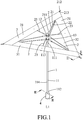
FIG. 1 is a perspective view of a first embodiment of a warning device according to the disclosure; -
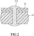
FIG. 2 is a fragmentary sectional view taken along line II-II inFIG. 1 ; -
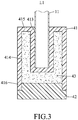
FIG. 3 is a fragmentary sectional view taken along line III-III inFIG. 1 ; -
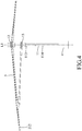
FIG. 4 is a fragmentary sectional view of the embodiment, illustrating a warning unit of the embodiment in an expanded state; -
FIG. 5 is another fragmentary sectional view of the embodiment, illustrating the warning unit in a collapsed state; -
FIG. 6 is a schematic view illustrating the embodiment placed behind a vehicle; -
FIG. 7 is a fragmentary perspective view of a second embodiment of the warning device according to the disclosure, illustrating a prop stand of the second embodiment in a non-propping position; -
FIG. 8 is a fragmentary perspective view of the second embodiment, illustrating the prop stand at a propping position; and -
FIG. 9 is a schematic top view of another embodiment of the warning device. - Before the present invention is described in greater detail, it should be noted that where considered appropriate, reference numerals or terminal portions of reference numerals have been repeated among the figures to indicate corresponding or analogous elements, which may optionally have similar characteristics.
- Referring to
FIGS. 1 to 3 , a first embodiment of a warning device according to the disclosure includes a supportingunit 1, a plurality of supportingframes 2, awarning unit 3, and ahandle unit 4. - The supporting
unit 1 includes a supportingrod 11 extending along an axis (L1), astationary seat 12 fixedly disposed at one end of the supportingrod 11, aslide seat 13 connected to the supportingrod 11 and being slidable along the supportingrod 11 relative to thestationary seat 12, and upper andlower spring tabs rod 11. The supportingrod 11 has afirst end portion 111 mounted to thestationary seat 12, and asecond end portion 112 opposite to thefirst end portion 111. Theupper spring tab 113 is disposed proximal to thefirst end portion 111, and thelower spring tab 114 is disposed proximal to thesecond end portion 114. - The supporting
frames 2 are equiangularly displaced about the axis (L1). In this embodiment, the number of the supportingframes 2 is three. Each of the supportingframes 2 has a connectingend portion 211 pivotally connected to thestationary seat 12, and adistal end portion 212 opposite to the connectingend portion 211. Thedistal end portion 212 of each of the supportingframes 2 is connected to theslide seat 13, such that theslide seat 13 is operable to drive each of thedistal end portions 212 of the supportingframes 2 to pivot between an expanded position (FIG. 4 ), where thedistal end portion 212 is distal from the supportingrod 11, and a collapsed position (FIG. 5 ), where thedistal end portion 212 is proximal to the supportingrod 11. In this embodiment, each of the supportingframes 2 includes anouter rod 21 pivotally connected to thestationary seat 12, and aninner rod 22 having opposite ends that are pivotally and respectively connected to theouter rod 21 and theslide seat 13. Theouter rods 21 has opposite end portions serving respectively as the connectingend portion 211 and thedistal end portion 212 of the supportingframe 2. - In this embodiment, the warning device further includes three
auxiliary rods 23 that are displaced angularly about the axis (L1) for providing auxiliary support. Each of theauxiliary rods 23 has a shorter length than each of the supportingframes 2. - The
warning unit 3 is mounted to the supportingframes 2 and is configured to be driven by the supportingframes 2 to be in an expanded state (FIG. 4 ) when thedistal end portion 212 of each of the supportingframes 2 is at the expanded position, and to be in a collapsed state (FIG. 5 ) when thedistal end portion 212 of each of the supportingframes 2 is at the collapsed position. Thewarning unit 3 includes at least onewarning member 31 made of a flexible material, and surrounding the axis (L1) and defining ahollow region 32 when thewarning unit 3 is in the expanded state. In this embodiment, the at least onewarning member 31 includes threewarning members 31 that form a hollow triangular structure when thewarning unit 3 is in the expanded state which forms a warning pattern in the form of an equilateral triangle. Each vertex of the triangular structure is formed by overlapping ends of a corresponding pair of thewarning members 31 and is mounted fixedly to a respective one of the supportingframes 2. In this embodiment, thewarning members 31 are sewn to each other, and each vertex of the triangular structure of thewarning unit 3 is riveted to thedistal end portion 212 of theouter rod 21 of the respective one of the supportingframes 2 by a rivet 213 (seeFIG. 2 ) . Thedistal end portion 212 of each of the supportingframes 2 protrudes out of thewarning unit 3. Specifically, the distance between thestationary seat 12 and the tip of thedistal end portion 212 of each of the supportingframes 2 is longer than that between thestationary seat 12 and the distal end of each vertex of the triangular structure of thewarning unit 3. Each of theauxiliary rods 23 has an end connected pivotally to thestationary seat 12, and an opposite end riveted to a middle section of a respective one of thewarning members 31. Theauxiliary rods 23 are disposed alternately with the supportingframes 2. - The
handle unit 4 is disposed on thesecond end portion 112 of the supportingrod 11. Thehandle unit 4 includes ahandle body 41, aweighted member 43 disposed inside thehandle body 41 and positioning a center of mass of the warning device proximal to thehandle unit 4, and aplug cover 42 secured to thehandle body 41 to retain the weightedmember 43 inside thehandle body 41. Thehandle body 41 has anend wall segment 415, and a surroundingwall segment 416 extending from theend wall segment 415. Theend wall segment 415 is indented to form afirst hole 413 that extends along the axis (L1), and the surroundingwall segment 416 cooperates with theend wall segment 415 to define asecond hole 414 that surrounds thefirst hole 413 and that has an opening. In this embodiment, thesecond end portion 112 of the supportingrod 11 is inserted into thefirst hole 413, theweighted member 43 is received in thesecond hole 414, and theplug cover 42 is coupled to the opening of thesecond hole 414. In this embodiment, theweighted member 43 is made of gravel, but is not limited thus and, in other embodiments, may be made of cement, concrete, metal, etc.. - Referring to
FIGS. 4 to 6 , to convert thewarning unit 3 to the expanded state, theslide seat 13 is moved along the supportingrod 11 and toward thestationary seat 12 to compress and slide over theupper spring tab 113, after which theupper spring tab 113 limits movement of theslide seat 13 away from thestationary seat 12. When theslide seat 13 is thus limited, thedistal end portion 212 of each of the supportingrods 2 is in the expanded position, and thewarning unit 3 is in the expanded state where the warning pattern is produced and where thehollow region 32 allows wind to flow through the warning device to thereby reduce wind resistance and allows the warning device to stand more stably on the ground. The warning device may be placed to the rear of avehicle 6 to warn approaching traffic when there is a vehicle breakdown or a traffic collision. To convert thewarning unit 3 to the collapsed state, theslide seat 13 is moved along the supportingrod 11 toward thehandle unit 4 so that thedistal end portion 212 of each of the supportingframes 2 is moved to the collapsed position. When thewarning unit 3 is in the collapsed state, theslide seat 13 may further be moved toward thehandle unit 4 to compress and slide over thelower spring tab 114, after which thelower spring tab 114 limits movement of theslide seat 13 toward thestationary seat 12. - It should be noted that in other embodiments, the
warning unit 3 may form a warning pattern in the form of a circle, or another polygon apart from triangles, such as a square. For example, thewarning unit 3 may include onewarning member 31 forming a circle pattern (seeFIG. 9 ), or fourwarning members 31 each serving as one side of a square pattern (not shown), and number of the supportingframes 2 may be adjusted accordingly. - In sum, the benefits of the warning device of the disclosure lies in that, by mounting the
warning unit 3 to the supportingframes 2 and through structural cooperation between the supportingunit 1 and the supportingframes 2, thewarning unit 3 may be quickly and easily converted between the collapsed state and the expanded state, which reduces amount of time needed for process of setting up the warning device on the roadside. The warning device is also compact when thewarning unit 3 is in the collapsed state, allowing for convenient storage and transport. - Referring to
FIGS. 7 and8 , a second embodiment of a warning device is similar to the first embodiment, but differs in further including aprop stand 5 mounted to thehandle unit 4. Theprop stand 5 is pivotable relative to thehandle unit 4 between a non-propping position (FIG. 7 ), where theprop stand 5 is substantially parallel to the axis (L1), and a propping position (FIG. 8 ), where theprop stand 5 extends obliquely to the axis (L1). The angle between theprop stand 5 and the axis (L1) may be adjusted to adjust an angle of thewarning unit 3 to the ground to increase visibility of the warning pattern to approaching traffic. The second embodiment has the same advantages as the first embodiment. - In the description above, for the purposes of explanation, numerous specific details have been set forth in order to provide a thorough understanding of the embodiments. It will be apparent, however, to one skilled in the art, that one or more other embodiments may be practiced without some of these specific details. It should also be appreciated that reference throughout this specification to "one embodiment," "an embodiment," an embodiment with an indication of an ordinal number and so forth means that a particular feature, structure, or characteristic may be included in the practice of the disclosure. It should be further appreciated that in the description, various features are sometimes grouped together in a single embodiment, figure, or description thereof for the purpose of streamlining the disclosure and aiding in the understanding of various inventive aspects, and that one or more features or specific details from one embodiment may be practiced together with one or more features or specific details from another embodiment, where appropriate, in the practice of the disclosure.
Claims (10)
- A warning device comprising:a supporting unit (1) including a supporting rod (11) that extends along an axis (L1), a stationary seat (12) that is fixedly disposed at one end of said supporting rod (11), and a slide seat (13) that is connected to said supporting rod (11) and that is slidable along said supporting rod (11) relative to said stationary seat (12);a plurality of supporting frames (2) equiangularly displaced about the axis (L1), each of said supporting frames (2) having a connecting end portion (211) that is pivotally connected to said stationary seat (12) and a distal end portion (212) that is opposite to said connecting end portion (211) and that is connected to said slide seat (13), such that said slide seat (13) is operable to drive each of said distal end portions (212) of said supporting frames (2) to pivot between an expanded position, where said distal end portion (212) is distal from said supporting rod (11), and a collapsed position, where said distal end portion (212) is proximal to said supporting rod (11); anda warning unit (3) mounted to said supporting frames (2) and configured to be driven by said supporting frames (2) to be in an expanded state when said distal end portion (212) of each of said supporting frames (2) is at the expanded position, and to be in a collapsed state when said distal end portion (212) of each of said supporting frames (2) is at the collapsed position;said warning device characterized in that said warning unit (3) includes at least one warning member (31) that is made of a flexible material, and that surrounds the axis (L1) and defines a hollow region (32) when said warning unit (3) is in the expanded state .
- The warning device as claimed in claim 1, further characterized in that said warning device further comprises a plurality of auxiliary rods (23) displaced angularly about the axis (L1) and disposed alternately with said supporting frames (2), each of said auxiliary rods (23) having a shorter length than each of said supporting frames (2).
- The warning device as claimed in claim 2, further characterized in that:the number of said supporting frames (2) is three; andsaid at least one warning member (31) includes three warning members (31).
- The warning device as claimed in claim 3, further characterized in that:said warning members (31) form a hollow triangular structure when said warning unit (3) is in the expanded state, each vertex of said triangular structure being formed by overlapping ends of a corresponding pair of said warning members (31) and being mounted fixedly to a respective one of said supporting frames (2);said distal end portion (212) of each of said supporting frames (2) protrudes out of said warning unit (3); andeach of said auxiliary rods (23) has an end connected pivotally to said stationary seat (12), and an opposite end mounted to a middle section of a respective one of said warning members (31).
- The warning device as claimed in claim 4, further characterized in that each of said supporting frames (2) includes:an outer rod (21) pivotally connected to said stationary seat (12), and having opposite end portions that serve respectively as said connecting end portion (211) and said distal end portion (212) of said supporting frame (2), each vertex of said triangular structure of said warning unit (3) being mounted fixedly to said outer rod (21) of the respective one of said supporting frames (2); andan inner rod (22) having opposite ends that are pivotally and respectively connected to said outer rod (21) and said slide seat (13).
- The warning device as claimed in claim 5, further characterized in that each vertex of said triangular structure of said warning unit (3) is riveted to said outer rod (21) of the respective one of said supporting frames (2).
- The warning device as claimed in any one of the previous claims, further characterized in that said supporting rod (11) of said supporting unit (1) has a first end portion (111) mounted to said stationary seat (12), and a second end portion (112) opposite to said first end portion (111), said warning device further comprising a handle unit (4) disposed on said second end portion (112) of said supporting rod (11).
- The warning device as claimed in claim 7, further characterized in that said warning device further comprises a prop stand (5) mounted to said handle unit (4) and pivotable relative to said handle unit (4) between a non-propping position, where said prop stand (5) is substantially parallel to said axis (L1), and a propping position, where said prop stand (5) extends obliquely to the axis (L1).
- The warning device as claimed in claim 7 or 8, further characterized in that said handle unit (4) includes a handle body (41), a weighted member (43) disposed inside said handle body (41) and positioning a center of mass of said warning device proximal to said handle unit (4), and a plug cover (42) secured to said handle body (41) to retain said weighted member (43) inside said handle body (41).
- The warning device as claimed in claim 9, further characterized in that:said handle body (41) hasan end wall segment (415) indented to form a first hole (413) that extends along the axis (L1), anda surrounding wall segment (416) extending from said end wall segment (415), and cooperating with said end wall segment (415) to define a second hole (414) that surrounds said first hole (413) and that has an opening;said second end portion (112) of said supporting rod (11) is inserted into said first hole (413); andsaid weighted member (43) is received in said second hole (414); andsaid plug cover (42) is coupled to said opening of said second hole (414).
Applications Claiming Priority (1)
| Application Number | Priority Date | Filing Date | Title |
|---|---|---|---|
| TW108125854A TWI708001B (en) | 2019-07-22 | 2019-07-22 | Warning device |
Publications (1)
| Publication Number | Publication Date |
|---|---|
| EP3770018A1 true EP3770018A1 (en) | 2021-01-27 |
Family
ID=71728553
Family Applications (1)
| Application Number | Title | Priority Date | Filing Date |
|---|---|---|---|
| EP20186450.1A Withdrawn EP3770018A1 (en) | 2019-07-22 | 2020-07-17 | Warning device |
Country Status (6)
| Country | Link |
|---|---|
| US (1) | US20210023989A1 (en) |
| EP (1) | EP3770018A1 (en) |
| JP (1) | JP2021017241A (en) |
| KR (1) | KR20210011888A (en) |
| CN (1) | CN112277793A (en) |
| TW (1) | TWI708001B (en) |
Families Citing this family (1)
| Publication number | Priority date | Publication date | Assignee | Title |
|---|---|---|---|---|
| KR102211501B1 (en) * | 2020-12-24 | 2021-02-03 | 이진우 | Portable muti-purpose safety triangle |
Citations (5)
| Publication number | Priority date | Publication date | Assignee | Title |
|---|---|---|---|---|
| KR20130003722A (en) * | 2011-06-30 | 2013-01-09 | 김진호 | Umbrella style safety triangle |
| KR20130135470A (en) * | 2012-06-01 | 2013-12-11 | 박태윤 | Umbrella type safety tripod |
| KR101519839B1 (en) * | 2014-11-06 | 2015-05-18 | (주)브링유 | Safety triangle for automobile |
| KR101528622B1 (en) * | 2014-04-01 | 2015-06-16 | 서승원 | safety sign apparatus |
| KR101982496B1 (en) * | 2018-05-31 | 2019-05-27 | 이상훈 | Apparatus For Emergency Lamp Shaped Like Umbrella |
Family Cites Families (8)
| Publication number | Priority date | Publication date | Assignee | Title |
|---|---|---|---|---|
| JPS55150806U (en) * | 1979-04-09 | 1980-10-30 | ||
| CN2430322Y (en) * | 2000-05-30 | 2001-05-16 | 刘勇进 | Warning rack for vehicle fault indicator |
| US7287538B2 (en) * | 2004-12-10 | 2007-10-30 | Fu Tai Umbrella Works, Ltd. | Illuminating umbrella grip |
| TWM446192U (en) * | 2012-05-25 | 2013-02-01 | Univ Far East | Umbrella type warning cone |
| TWM499627U (en) * | 2014-11-20 | 2015-04-21 | Yi Jiang | Improvement of tripod structure |
| CN205211354U (en) * | 2015-12-01 | 2016-05-04 | 宁波肖东实业有限公司 | Multifunctional safety warning device |
| CN206443328U (en) * | 2017-02-15 | 2017-08-29 | 广州厚大技术服务有限公司 | A kind of safety umbrella with warning |
| CN107594794A (en) * | 2017-08-04 | 2018-01-19 | 浙江天合雨具设计有限公司 | One kind is rubbed a large bamboo or straw hat with a concial crown, broard brim and handle umbrella |
-
2019
- 2019-07-22 TW TW108125854A patent/TWI708001B/en not_active IP Right Cessation
-
2020
- 2020-07-15 CN CN202010677865.7A patent/CN112277793A/en active Pending
- 2020-07-17 EP EP20186450.1A patent/EP3770018A1/en not_active Withdrawn
- 2020-07-20 US US16/933,960 patent/US20210023989A1/en not_active Abandoned
- 2020-07-21 KR KR1020200090265A patent/KR20210011888A/en not_active Ceased
- 2020-07-21 JP JP2020124303A patent/JP2021017241A/en active Pending
Patent Citations (5)
| Publication number | Priority date | Publication date | Assignee | Title |
|---|---|---|---|---|
| KR20130003722A (en) * | 2011-06-30 | 2013-01-09 | 김진호 | Umbrella style safety triangle |
| KR20130135470A (en) * | 2012-06-01 | 2013-12-11 | 박태윤 | Umbrella type safety tripod |
| KR101528622B1 (en) * | 2014-04-01 | 2015-06-16 | 서승원 | safety sign apparatus |
| KR101519839B1 (en) * | 2014-11-06 | 2015-05-18 | (주)브링유 | Safety triangle for automobile |
| KR101982496B1 (en) * | 2018-05-31 | 2019-05-27 | 이상훈 | Apparatus For Emergency Lamp Shaped Like Umbrella |
Also Published As
| Publication number | Publication date |
|---|---|
| TWI708001B (en) | 2020-10-21 |
| TW202104725A (en) | 2021-02-01 |
| JP2021017241A (en) | 2021-02-15 |
| US20210023989A1 (en) | 2021-01-28 |
| KR20210011888A (en) | 2021-02-02 |
| CN112277793A (en) | 2021-01-29 |
Similar Documents
| Publication | Publication Date | Title |
|---|---|---|
| US4548379A (en) | Compact sign and stand | |
| US4593879A (en) | Compact sign stand | |
| US7571693B2 (en) | Condensed retractable safety marker | |
| US5799786A (en) | Golf bag with stand | |
| US4691892A (en) | Sign and sign stand | |
| US6010101A (en) | Automatic golf bag support stand | |
| US4662305A (en) | Collapsible signpost | |
| EP0352386B1 (en) | Foldable warning distress sign | |
| US7007420B2 (en) | Barricade sign | |
| DE6917029U (en) | GUIDE CONES FOR WARNING AND SAFETY PURPOSES IN ROAD TRAFFIC | |
| EP0296266A1 (en) | Portable collapsible highway sign | |
| US20060225319A1 (en) | Portable information sign devices | |
| US20210023989A1 (en) | Warning device | |
| EP0823510A2 (en) | Collapsable guide sign | |
| US7062872B2 (en) | Lightweight collapsible signaling device | |
| US9262949B1 (en) | Portable collapsible fabric-tensioned sign assembly | |
| GB2108182A (en) | Portable self-righting road- marker | |
| US4047798A (en) | Emergency signalling device | |
| US20180320326A1 (en) | Location marker | |
| CN211285365U (en) | Safety parking tripod | |
| US11674275B2 (en) | Retractable safety marker | |
| WO1990011408A1 (en) | Collapsible warning stand | |
| AU2005100792A4 (en) | A sign post | |
| AU2004260814B2 (en) | A sign post | |
| CN213038239U (en) | Warning board for highway |
Legal Events
| Date | Code | Title | Description |
|---|---|---|---|
| PUAI | Public reference made under article 153(3) epc to a published international application that has entered the european phase |
Free format text: ORIGINAL CODE: 0009012 |
|
| STAA | Information on the status of an ep patent application or granted ep patent |
Free format text: STATUS: THE APPLICATION HAS BEEN PUBLISHED |
|
| AK | Designated contracting states |
Kind code of ref document: A1 Designated state(s): AL AT BE BG CH CY CZ DE DK EE ES FI FR GB GR HR HU IE IS IT LI LT LU LV MC MK MT NL NO PL PT RO RS SE SI SK SM TR |
|
| AX | Request for extension of the european patent |
Extension state: BA ME |
|
| STAA | Information on the status of an ep patent application or granted ep patent |
Free format text: STATUS: THE APPLICATION IS DEEMED TO BE WITHDRAWN |
|
| 18D | Application deemed to be withdrawn |
Effective date: 20210728 |