EP3769947A1 - Hybrid metallic/composite tube design to transfer bending, axial, and flexural shear - Google Patents
Hybrid metallic/composite tube design to transfer bending, axial, and flexural shear Download PDFInfo
- Publication number
- EP3769947A1 EP3769947A1 EP19215839.2A EP19215839A EP3769947A1 EP 3769947 A1 EP3769947 A1 EP 3769947A1 EP 19215839 A EP19215839 A EP 19215839A EP 3769947 A1 EP3769947 A1 EP 3769947A1
- Authority
- EP
- European Patent Office
- Prior art keywords
- composite tube
- tube
- end fitting
- flared
- terminating
- Prior art date
- Legal status (The legal status is an assumption and is not a legal conclusion. Google has not performed a legal analysis and makes no representation as to the accuracy of the status listed.)
- Granted
Links
Images

Classifications
-
- B—PERFORMING OPERATIONS; TRANSPORTING
- B29—WORKING OF PLASTICS; WORKING OF SUBSTANCES IN A PLASTIC STATE IN GENERAL
- B29C—SHAPING OR JOINING OF PLASTICS; SHAPING OF MATERIAL IN A PLASTIC STATE, NOT OTHERWISE PROVIDED FOR; AFTER-TREATMENT OF THE SHAPED PRODUCTS, e.g. REPAIRING
- B29C70/00—Shaping composites, i.e. plastics material comprising reinforcements, fillers or preformed parts, e.g. inserts
- B29C70/68—Shaping composites, i.e. plastics material comprising reinforcements, fillers or preformed parts, e.g. inserts by incorporating or moulding on preformed parts, e.g. inserts or layers, e.g. foam blocks
- B29C70/86—Incorporated in coherent impregnated reinforcing layers, e.g. by winding
-
- F—MECHANICAL ENGINEERING; LIGHTING; HEATING; WEAPONS; BLASTING
- F16—ENGINEERING ELEMENTS AND UNITS; GENERAL MEASURES FOR PRODUCING AND MAINTAINING EFFECTIVE FUNCTIONING OF MACHINES OR INSTALLATIONS; THERMAL INSULATION IN GENERAL
- F16C—SHAFTS; FLEXIBLE SHAFTS; ELEMENTS OR CRANKSHAFT MECHANISMS; ROTARY BODIES OTHER THAN GEARING ELEMENTS; BEARINGS
- F16C7/00—Connecting-rods or like links pivoted at both ends; Construction of connecting-rod heads
- F16C7/02—Constructions of connecting-rods with constant length
-
- B—PERFORMING OPERATIONS; TRANSPORTING
- B29—WORKING OF PLASTICS; WORKING OF SUBSTANCES IN A PLASTIC STATE IN GENERAL
- B29C—SHAPING OR JOINING OF PLASTICS; SHAPING OF MATERIAL IN A PLASTIC STATE, NOT OTHERWISE PROVIDED FOR; AFTER-TREATMENT OF THE SHAPED PRODUCTS, e.g. REPAIRING
- B29C37/00—Component parts, details, accessories or auxiliary operations, not covered by group B29C33/00 or B29C35/00
- B29C37/0078—Measures or configurations for obtaining anchoring effects in the contact areas between layers
- B29C37/0082—Mechanical anchoring
-
- F—MECHANICAL ENGINEERING; LIGHTING; HEATING; WEAPONS; BLASTING
- F16—ENGINEERING ELEMENTS AND UNITS; GENERAL MEASURES FOR PRODUCING AND MAINTAINING EFFECTIVE FUNCTIONING OF MACHINES OR INSTALLATIONS; THERMAL INSULATION IN GENERAL
- F16D—COUPLINGS FOR TRANSMITTING ROTATION; CLUTCHES; BRAKES
- F16D1/00—Couplings for rigidly connecting two coaxial shafts or other movable machine elements
- F16D1/06—Couplings for rigidly connecting two coaxial shafts or other movable machine elements for attachment of a member on a shaft or on a shaft-end
-
- B—PERFORMING OPERATIONS; TRANSPORTING
- B29—WORKING OF PLASTICS; WORKING OF SUBSTANCES IN A PLASTIC STATE IN GENERAL
- B29L—INDEXING SCHEME ASSOCIATED WITH SUBCLASS B29C, RELATING TO PARTICULAR ARTICLES
- B29L2031/00—Other particular articles
- B29L2031/06—Rods, e.g. connecting rods, rails, stakes
-
- B—PERFORMING OPERATIONS; TRANSPORTING
- B29—WORKING OF PLASTICS; WORKING OF SUBSTANCES IN A PLASTIC STATE IN GENERAL
- B29L—INDEXING SCHEME ASSOCIATED WITH SUBCLASS B29C, RELATING TO PARTICULAR ARTICLES
- B29L2031/00—Other particular articles
- B29L2031/748—Machines or parts thereof not otherwise provided for
- B29L2031/75—Shafts
-
- F—MECHANICAL ENGINEERING; LIGHTING; HEATING; WEAPONS; BLASTING
- F16—ENGINEERING ELEMENTS AND UNITS; GENERAL MEASURES FOR PRODUCING AND MAINTAINING EFFECTIVE FUNCTIONING OF MACHINES OR INSTALLATIONS; THERMAL INSULATION IN GENERAL
- F16C—SHAFTS; FLEXIBLE SHAFTS; ELEMENTS OR CRANKSHAFT MECHANISMS; ROTARY BODIES OTHER THAN GEARING ELEMENTS; BEARINGS
- F16C2226/00—Joining parts; Fastening; Assembling or mounting parts
- F16C2226/50—Positive connections
- F16C2226/80—Positive connections with splines, serrations or similar profiles to prevent movement between joined parts
-
- F—MECHANICAL ENGINEERING; LIGHTING; HEATING; WEAPONS; BLASTING
- F16—ENGINEERING ELEMENTS AND UNITS; GENERAL MEASURES FOR PRODUCING AND MAINTAINING EFFECTIVE FUNCTIONING OF MACHINES OR INSTALLATIONS; THERMAL INSULATION IN GENERAL
- F16C—SHAFTS; FLEXIBLE SHAFTS; ELEMENTS OR CRANKSHAFT MECHANISMS; ROTARY BODIES OTHER THAN GEARING ELEMENTS; BEARINGS
- F16C2240/00—Specified values or numerical ranges of parameters; Relations between them
- F16C2240/40—Linear dimensions, e.g. length, radius, thickness, gap
-
- F—MECHANICAL ENGINEERING; LIGHTING; HEATING; WEAPONS; BLASTING
- F16—ENGINEERING ELEMENTS AND UNITS; GENERAL MEASURES FOR PRODUCING AND MAINTAINING EFFECTIVE FUNCTIONING OF MACHINES OR INSTALLATIONS; THERMAL INSULATION IN GENERAL
- F16C—SHAFTS; FLEXIBLE SHAFTS; ELEMENTS OR CRANKSHAFT MECHANISMS; ROTARY BODIES OTHER THAN GEARING ELEMENTS; BEARINGS
- F16C2240/00—Specified values or numerical ranges of parameters; Relations between them
- F16C2240/40—Linear dimensions, e.g. length, radius, thickness, gap
- F16C2240/70—Diameters; Radii
-
- F—MECHANICAL ENGINEERING; LIGHTING; HEATING; WEAPONS; BLASTING
- F16—ENGINEERING ELEMENTS AND UNITS; GENERAL MEASURES FOR PRODUCING AND MAINTAINING EFFECTIVE FUNCTIONING OF MACHINES OR INSTALLATIONS; THERMAL INSULATION IN GENERAL
- F16C—SHAFTS; FLEXIBLE SHAFTS; ELEMENTS OR CRANKSHAFT MECHANISMS; ROTARY BODIES OTHER THAN GEARING ELEMENTS; BEARINGS
- F16C7/00—Connecting-rods or like links pivoted at both ends; Construction of connecting-rod heads
- F16C7/02—Constructions of connecting-rods with constant length
- F16C7/026—Constructions of connecting-rods with constant length made of fibre reinforced resin
-
- F—MECHANICAL ENGINEERING; LIGHTING; HEATING; WEAPONS; BLASTING
- F16—ENGINEERING ELEMENTS AND UNITS; GENERAL MEASURES FOR PRODUCING AND MAINTAINING EFFECTIVE FUNCTIONING OF MACHINES OR INSTALLATIONS; THERMAL INSULATION IN GENERAL
- F16D—COUPLINGS FOR TRANSMITTING ROTATION; CLUTCHES; BRAKES
- F16D1/00—Couplings for rigidly connecting two coaxial shafts or other movable machine elements
- F16D1/06—Couplings for rigidly connecting two coaxial shafts or other movable machine elements for attachment of a member on a shaft or on a shaft-end
- F16D1/064—Couplings for rigidly connecting two coaxial shafts or other movable machine elements for attachment of a member on a shaft or on a shaft-end non-disconnectable
Definitions
- the present disclosure relates generally to joints, and more specifically to joints having composite components.
- a tube arrangement comprising a composite tube defining a centerline axis, wherein the composite tube comprises a proximal surface and a distal surface, and an end fitting comprising a first end disposed within the composite tube and a second end extending from the composite tube.
- An outer surface of the end fitting defines a flared portion defining a terminus of the first end, a lobe portion disposed axially from the flared portion, and a terminating portion disposed axially from the lobe portion.
- the proximal surface conforms to a geometry of the outer surface of the end fitting.
- the lobe portion and the flared portion mechanically lock the end fitting to the composite tube to mitigate movement of the end fitting relative to the composite tube.
- the lobe portion defines an annular ridge disposed around the end fitting.
- the annular ridge defines a first convex fitting surface.
- annular groove is formed into the proximal surface of the composite tube, the annular groove receives the lobe portion.
- the annular groove defines a concave tube surface.
- annular protrusion is formed into the proximal surface of the composite tube, the annular protrusion is in contact with the lobe portion and the flared portion.
- the annular protrusion defines a convex tube surface.
- the flared portion defines a second convex fitting surface.
- the terminating portion defines a concave fitting surface.
- the concave fitting surface is rounded.
- the composite tube terminates at the terminating portion.
- a combined axial length of the flared portion, the lobe portion, and the terminating portion is between one and three times the maximum diameter of the flared portion.
- the end fitting is monolithic.
- a tube arrangement comprising a composite tube defining a centerline axis, wherein the composite tube comprises a proximal surface and a distal surface, and an end fitting comprising a first end disposed within the composite tube and a second end extending from the composite tube.
- An outer surface of the end fitting defines a flared portion defining a terminus of the first end, a lobe portion disposed axially from the flared portion, and a terminating portion disposed axially from the lobe portion, the terminating portion defines a second flared portion, the second flared portion defining a concave fitting surface, wherein the concave fitting surface is rounded, the composite tube terminates at the terminating portion, and the composite tube comprises a rounded, flared proximal surface terminating at the terminating portion.
- an axial length of the flared portion is between 0.3 and 0.7 times the maximum diameter of the flared portion.
- an axial length of the lobe portion is between 0.6 and 1.2 times the maximum diameter of the lobe portion.
- an axial length of the terminating portion is between 0.2 and 0.6 times the minimum diameter of the terminating portion.
- an axial length between a terminus of the end fitting and a terminus of the terminating portion is between one and three times the maximum diameter of the flared portion.
- a method for manufacturing a tube arrangement comprising disposing a composite material about an end fitting to form a composite tube defining a centerline axis, wherein the composite tube comprises a proximal surface and a distal surface, and the end fitting comprises a first end disposed within the composite tube and a second end extending from the composite tube, wherein an outer surface of the end fitting defines a flared portion defining a terminus of the first end, a lobe portion disposed axially from the flared portion, and a terminating portion disposed axially from the lobe portion, the proximal surface conforms to a geometry of the outer surface of the end fitting, and the lobe portion and the flared portion mechanically lock the end fitting to the composite tube to mitigate movement of the end fitting relative to the composite tube.
- the composite tube terminates at the terminating portion.
- any reference to attached, fixed, connected or the like may include permanent, removable, temporary, partial, full and/or any other possible attachment option. Additionally, any reference to without contact (or similar phrases) may also include reduced contact or minimal contact. Surface shading lines may be used throughout the figures to denote different parts but not necessarily to denote the same or different materials. In some cases, reference coordinates may be specific to each figure.
- distal refers to the direction radially outward, or generally, away from the centerline axis of a tube.
- proximal refers to a direction radially inward, or generally, towards the centerline axis of a tube.
- the term “concave surface” refers to a surface having an outline or periphery that curves inward like the interior of a circle or spheroid.
- the term “convex surface” refers to a surface having an outline or periphery that curves outward like the exterior of a circle or spheroid.
- the present disclosure describes composite tube arrangements having a composite tube and at least one end fitting.
- the end fitting may be made from a metallic material.
- a composite may comprise a polymer matrix composite.
- the composite may comprise a polymer matrix composite reinforced by fibers such as a carbon, glass, organic fibers, or combinations thereof.
- Such composite tube joints may be used in aircraft systems, such as, for example, landing gear systems.
- the systems and methods of the present disclosure may be suitable for use in non-aircraft systems as well.
- a hybrid metallic/composite tube joint of the present disclosure may include an end of a composite tube and an end fitting.
- a composite tube joint may experience bending loads.
- Composite tube joints having a flared terminus, a lobe portion, and a terminating portion, of the present disclosure, may mitigate slipping of the composite tube with respect to the end fitting, and may reduce stress and flexural shear in the composite tube when under bending loads.
- a composite tube joint of the present disclosure may be useful for various components including, but not limited to, linkages, connecting rods, actuator rods, struts, structural supports, etc.
- Hybrid metallic/composite tube joint 201 and hybrid metallic/composite tube joint 202 may be disposed at either end of a composite tube 200.
- composite tube 200 may comprise only one hybrid metallic/composite tube joint 201 at an end thereof.
- hybrid metallic/composite tube joint 202 may experience an axial load, represented by arrows 290.
- the axial load may be a tensile load or a compressive load.
- Hybrid metallic/composite tube joint 202 may experience a bending moment, represented by arrows 292.
- Hybrid metallic/composite tube joint 202 may experience a flexural shear load, represented by arrows 294.
- Tube arrangement 300 (also referred to herein as a hybrid metallic/composite tube arrangement) is illustrated, in accordance with various embodiments.
- Tube arrangement 300 generally comprises a composite tube 302 and at least one end fitting, such as end fitting 304 and/or end fitting 306.
- Composite tube 302 may define a centerline axis 390.
- Composite tube 302 and end fitting 304 may be coaxially disposed about centerline axis 390.
- Composite tube 302 and end fitting 306 may be coaxially disposed about centerline axis 390.
- Composite tube 302 may comprise a proximal surface 310 and a distal surface 311.
- a cross-section geometry (e.g., taken perpendicular to centerline axis 390) of composite tube 302 may be circular or may be non-circular (e.g., elliptical). Centerline axis 390 may be linear or may be non-linear.
- end fitting 304 and/or end fitting 306 are configured to couple composite tube 302 to an adjacent component.
- End fitting 304 and/or end fitting 306 may comprise any suitable attachment feature, including a lug, a clevis, a rod, or the like.
- end fitting 304 and/or end fitting 306 are made from a metallic material.
- end fitting 304 is formed as a single, monolithic piece.
- end fitting 306 is formed as a single, monolithic piece.
- End fitting 304 and/or end fitting 306 may be configured to transfer loads (e.g., axial loads, bending loads, and/or flexural shear loads) between composite tube 302 and end fitting 304 and/or end fitting 306, respectively.
- end fitting 304 comprises a first end 321 disposed within composite tube 302 and a second end 322 extending from composite tube 302.
- an outer surface 323 of end fitting 304 may define a flared portion (also referred to herein as a first flared portion) 410.
- Flared portion 410 may define a terminus 324 of first end 321.
- flared portion 410 defines a convex surface 412 (also referred to herein as a second convex fitting surface).
- flared portion 410 may be rounded or curved.
- Outer surface 323 of end fitting 304 may define a lobe portion 420.
- Lobe portion 420 may be disposed axially from flared portion 410.
- Lobe portion 420 may be axially adjacent flared portion 410.
- lobe portion 420 defines a convex surface 422 (also referred to herein as a first convex fitting surface).
- lobe portion 420 may be rounded or curved.
- lobe portion 420 defines an annular ridge 423 disposed perimetrically around the end fitting 304. The annular ridge 423 may define the convex surface 422.
- Outer surface 323 of end fitting 304 may define a terminating portion 430.
- Terminating portion 430 may be disposed axially from lobe portion 420.
- Terminating portion 430 may be axially adjacent lobe portion 420.
- Lobe portion 420 may be disposed axially between terminating portion 430 and flared portion 410.
- Composite tube 302 may terminate at terminating portion 430.
- terminating portion 430 defines a cylindrical surface 432.
- terminating portion 430 may comprise a constant diameter, in accordance with various embodiments.
- terminating portion 430 may be tapered.
- Composite tube 302 may be formed around end fitting 304 in a known manner during manufacture of tube arrangement 300 using, for example, a filament winding process, and/or a resin film infusion process, among others.
- composite tube 302 may comprise a fiber-reinforced polymer.
- the proximal surface 310 of composite tube 302 may conform to the geometry of outer surface 323 of end fitting 304.
- an annular groove 314 may be formed into the proximal surface 310 of the composite tube 302.
- the annular groove 314 may define a concave surface 315 (also referred to herein as a concave tube surface).
- the annular groove 314 may receive the lobe portion 420.
- annular protrusion 316 may be formed into the proximal surface 310 of the composite tube 302.
- the annular protrusion 316 may define a convex surface 317 (also referred to herein as a convex tube surface).
- the annular protrusion 316 may be in contact with the lobe portion 420 and the flared portion 410.
- the annular protrusion 316 may be partially formed by the lobe portion 420 and partially formed by the flared portion 410.
- the maximum diameter D1 of terminating portion 430 may be less than the maximum diameter D2 of lobe portion 420.
- the minimum inside diameter D4 of annular protrusion 316 may be less than the maximum outside diameter D3 of flared portion 410. In this manner, the lobe portion 420 and the flared portion 410, together with composite tube 302, mechanically lock the end fitting 304 to the composite tube 302 to mitigate movement of the end fitting 304 relative to the composite tube 302.
- the axial length L1 of flared portion 410 may be equal to between 0.3 and 0.7 times the maximum diameter D3 of flared portion 410.
- the axial length L2 of lobe portion 420 may be equal to between 0.6 and 1.0 times the maximum diameter D2 of lobe portion 420.
- the axial length L3 of terminating portion 430 may be equal to between 0.2 and 0.6 times the maximum diameter D1 of terminating portion 430.
- end fitting 306 may be similar to end fitting 304, except that the terminating surface of end fitting 306 comprises a flared portion defining a rounded, concave surface. In this manner, end fitting 306 may effectively transfer bending loads between end fitting 306 and composite tube 302, reducing the amount of stress at the terminus of composite tube 302.
- end fitting 304 may be configured for applications where the bending moment is less dominant.
- end fitting 306 may be configured for applications where the bending moment is more dominant.
- end fitting 306 comprises a first end 331 disposed within composite tube 302 and a second end 332 extending from composite tube 302.
- an outer surface 333 of end fitting 306 may define a flared portion (also referred to herein as a first flared portion) 510.
- Flared portion 510 may define a terminus 334 of first end 331.
- flared portion 510 defines a convex surface 512 (also referred to herein as a second convex fitting surface).
- flared portion 510 may be rounded or curved.
- Outer surface 333 of end fitting 306 may define a lobe portion 520.
- Lobe portion 520 may be disposed axially from flared portion 510.
- Lobe portion 520 may be axially adjacent flared portion 510.
- lobe portion 520 defines a convex surface 522 (also referred to herein as a first convex fitting surface).
- lobe portion 520 may be rounded or curved.
- lobe portion 520 defines an annular ridge 523 disposed perimetrically around the end fitting 306. The annular ridge 523 may define the convex surface 522.
- Outer surface 333 of end fitting 306 may define a terminating portion 530.
- Terminating portion 530 may be disposed axially from lobe portion 520.
- Terminating portion 530 may be axially adjacent lobe portion 520.
- Lobe portion 520 may be disposed axially between terminating portion 530 and flared portion 510.
- Composite tube 302 may terminate at terminating portion 530.
- terminating portion 530 is flared outward (i.e., away from centerline axis 390).
- terminating portion 530 may be referred to herein as a flared portion or a second flared portion.
- terminating portion 530 defines a concave surface 532 (also referred to herein as a concave fitting surface).
- terminating portion 530 may be rounded or curved, in accordance with various embodiments.
- the terminus of composite tube 302 which terminates at terminating portion 530 may comprise a rounded, flared proximal surface 349 conforming to the geometry of terminating portion 530.
- Composite tube 302 may be formed around end fitting 306 in a known manner during manufacture of tube arrangement 300 using, for example, a filament winding process, and/or a resin film infusion process, among others.
- the proximal surface 310 of composite tube 302 may conform to the geometry of outer surface 333 of end fitting 306.
- an annular groove 344 may be formed into the proximal surface 310 of the composite tube 302.
- the annular groove 344 may define a concave surface 345 (also referred to herein as a concave tube surface).
- the annular groove 344 may receive the lobe portion 520.
- an annular protrusion 346 may be formed into the proximal surface 310 of the composite tube 302.
- the annular protrusion 346 may define a convex surface 347 (also referred to herein as a convex tube surface).
- the annular protrusion 346 may be in contact with the lobe portion 520 and the flared portion 510. Stated differently, the annular protrusion 346 may be partially formed by the lobe portion 520 and partially formed by the flared portion 510.
- the minimum diameter D5 of terminating portion 530 may be less than the maximum diameter D6 of lobe portion 520.
- the minimum inside diameter D8 of annular protrusion 346 may be less than the maximum outside diameter D7 of flared portion 510. In this manner, the lobe portion 520 and the flared portion 510, together with composite tube 302, mechanically lock the end fitting 306 to the composite tube 302 to mitigate movement of the end fitting 306 relative to the composite tube 302.
- the axial length L4 of flared portion 510 may be equal to between 0.3 and 0.7 times the maximum diameter D7 of flared portion 510.
- the axial length L5 of lobe portion 520 may be equal to between 0.6 and 1.2 times the maximum diameter D6 of lobe portion 520.
- the axial length L6 of terminating portion 530 may be equal to between 0.2 and 0.6 times the minimum diameter D5 of terminating portion 530.
- the total combined axial length L7 of flared portion 410, lobe portion 420, and terminating portion 430 may be between 1 and 3 times the maximum diameter D7 of flared portion 510 (1 ⁇ L7/D7 ⁇ 3).
- the axial length L7 between terminus 334 (see FIG. 3B ) and the end 502 of terminating portion 530 may be between 1 and 3 times the maximum diameter D7 of flared portion 510.
- the total combined axial length L7 of flared portion 410, lobe portion 420, and terminating portion 430 may be between 1.4 and 2 times the maximum diameter D7 of flared portion 510 (1.4 ⁇ L7/D7 ⁇ 2).
- end fitting 306 and composite tube 302 are illustrated experiencing combined axial, bending, and flexural loads. End fitting 306 may effectively transfer these loads between end fitting 306 and composite tube 302, reducing the amount of stress around the terminus 602 of composite tube 302 due to the shape of end fitting 306 at and around terminus 602.
- references to "one embodiment,” “an embodiment,” “an example embodiment,” etc. indicate that the embodiment described may include a particular feature, structure, or characteristic, but every embodiment may not necessarily include the particular feature, structure, or characteristic. Moreover, such phrases are not necessarily referring to the same embodiment. Further, when a particular feature, structure, or characteristic is described in connection with an embodiment, it is submitted that it is within the knowledge of one skilled in the art to affect such feature, structure, or characteristic in connection with other embodiments whether or not explicitly described. After reading the description, it will be apparent to one skilled in the relevant art(s) how to implement the disclosure in alternative embodiments.
Landscapes
- Engineering & Computer Science (AREA)
- General Engineering & Computer Science (AREA)
- Mechanical Engineering (AREA)
- Chemical & Material Sciences (AREA)
- Composite Materials (AREA)
- Rigid Pipes And Flexible Pipes (AREA)
Abstract
Description
- The present disclosure relates generally to joints, and more specifically to joints having composite components.
- Conventional structural components, for example aircraft landing gear components, are typically made of metallic materials. These metallic components can be relatively heavy and costly. Substitution of metals with composites is one way to reduce the weight and cost of structural components. Among other challenges is implementation of strong joints for load transfer from composite elements to metallic parts. The composite elements are typically fabricated in the form of tubes and are capable of handling significant axial and bending loads under both tension and compression.
- A tube arrangement is disclosed, comprising a composite tube defining a centerline axis, wherein the composite tube comprises a proximal surface and a distal surface, and an end fitting comprising a first end disposed within the composite tube and a second end extending from the composite tube. An outer surface of the end fitting defines a flared portion defining a terminus of the first end, a lobe portion disposed axially from the flared portion, and a terminating portion disposed axially from the lobe portion. The proximal surface conforms to a geometry of the outer surface of the end fitting. The lobe portion and the flared portion mechanically lock the end fitting to the composite tube to mitigate movement of the end fitting relative to the composite tube.
- In various embodiments, the lobe portion defines an annular ridge disposed around the end fitting.
- In various embodiments, the annular ridge defines a first convex fitting surface.
- In various embodiments, an annular groove is formed into the proximal surface of the composite tube, the annular groove receives the lobe portion.
- In various embodiments, the annular groove defines a concave tube surface.
- In various embodiments, an annular protrusion is formed into the proximal surface of the composite tube, the annular protrusion is in contact with the lobe portion and the flared portion.
- In various embodiments, the annular protrusion defines a convex tube surface.
- In various embodiments, the flared portion defines a second convex fitting surface.
- In various embodiments, the terminating portion defines a concave fitting surface.
- In various embodiments, the concave fitting surface is rounded.
- In various embodiments, the composite tube terminates at the terminating portion.
- In various embodiments, a combined axial length of the flared portion, the lobe portion, and the terminating portion is between one and three times the maximum diameter of the flared portion.
- In various embodiments, the end fitting is monolithic.
- A tube arrangement is disclosed, comprising a composite tube defining a centerline axis, wherein the composite tube comprises a proximal surface and a distal surface, and an end fitting comprising a first end disposed within the composite tube and a second end extending from the composite tube. An outer surface of the end fitting defines a flared portion defining a terminus of the first end, a lobe portion disposed axially from the flared portion, and a terminating portion disposed axially from the lobe portion, the terminating portion defines a second flared portion, the second flared portion defining a concave fitting surface, wherein the concave fitting surface is rounded, the composite tube terminates at the terminating portion, and the composite tube comprises a rounded, flared proximal surface terminating at the terminating portion.
- In various embodiments, an axial length of the flared portion is between 0.3 and 0.7 times the maximum diameter of the flared portion.
- In various embodiments, an axial length of the lobe portion is between 0.6 and 1.2 times the maximum diameter of the lobe portion.
- In various embodiments, an axial length of the terminating portion is between 0.2 and 0.6 times the minimum diameter of the terminating portion.
- In various embodiments, an axial length between a terminus of the end fitting and a terminus of the terminating portion is between one and three times the maximum diameter of the flared portion.
- A method for manufacturing a tube arrangement is disclosed, comprising disposing a composite material about an end fitting to form a composite tube defining a centerline axis, wherein the composite tube comprises a proximal surface and a distal surface, and the end fitting comprises a first end disposed within the composite tube and a second end extending from the composite tube, wherein an outer surface of the end fitting defines a flared portion defining a terminus of the first end, a lobe portion disposed axially from the flared portion, and a terminating portion disposed axially from the lobe portion, the proximal surface conforms to a geometry of the outer surface of the end fitting, and the lobe portion and the flared portion mechanically lock the end fitting to the composite tube to mitigate movement of the end fitting relative to the composite tube.
- In various embodiments, the composite tube terminates at the terminating portion.
- The foregoing features and elements may be combined in various combinations without exclusivity, unless expressly indicated herein otherwise. These features and elements as well as the operation of the disclosed embodiments will become more apparent in light of the following description and accompanying drawings.
- The subject matter of the present disclosure is particularly pointed out and distinctly claimed in the concluding portion of the specification. A more complete understanding of the present disclosure, however, may best be obtained by referring to the detailed description and claims when considered in connection with the drawing figures, wherein like numerals denote like elements.
-
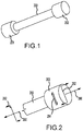
FIG. 1 illustrates a tube arrangement comprising hybrid metallic/composite tube joints at the ends thereof, in accordance with various embodiments; -
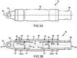
FIG. 2 illustrates a hybrid metallic/composite tube joint of the tube arrangement ofFIG. 1 experiencing bending and axial loads, in accordance with various embodiments; -
FIG. 3A illustrates a tube arrangement comprising hybrid metallic/composite tube joints at the ends thereof, in accordance with various embodiments; -
FIG. 3B illustrates a cross-section view of the tube arrangement ofFIG. 3A , in accordance with various embodiments; -
FIG. 4 illustrates a side view of an end fitting having a flared portion, a lobe portion, and a terminating portion, in accordance with various embodiments; -
FIG. 5 illustrates a side view of an end fitting having a flared portion, a lobe portion, and a terminating portion, in accordance with various embodiments; and -
FIG. 6 illustrates a cross-section view of a hybrid metallic/composite tube joint experiencing a bending load, in accordance with various embodiments. - The detailed description of exemplary embodiments herein makes reference to the accompanying drawings, which show exemplary embodiments by way of illustration. While these exemplary embodiments are described in sufficient detail to enable those skilled in the art to practice the inventions, it should be understood that other embodiments may be realized and that logical changes and adaptations in design and construction may be made in accordance with this invention and the teachings herein. Thus, the detailed description herein is presented for purposes of illustration only and not for limitation. The scope of the invention is defined by the appended claims. For example, the steps recited in any of the method or process descriptions may be executed in any order and are not necessarily limited to the order presented. Furthermore, any reference to singular includes plural embodiments, and any reference to more than one component or step may include a singular embodiment or step. Also, any reference to attached, fixed, connected or the like may include permanent, removable, temporary, partial, full and/or any other possible attachment option. Additionally, any reference to without contact (or similar phrases) may also include reduced contact or minimal contact. Surface shading lines may be used throughout the figures to denote different parts but not necessarily to denote the same or different materials. In some cases, reference coordinates may be specific to each figure.
- As used herein, "distal" refers to the direction radially outward, or generally, away from the centerline axis of a tube. As used herein, "proximal" refers to a direction radially inward, or generally, towards the centerline axis of a tube.
- As used herein, the term "concave surface" refers to a surface having an outline or periphery that curves inward like the interior of a circle or spheroid. As used herein, the term "convex surface" refers to a surface having an outline or periphery that curves outward like the exterior of a circle or spheroid.
- The present disclosure describes composite tube arrangements having a composite tube and at least one end fitting. The end fitting may be made from a metallic material. A composite may comprise a polymer matrix composite. The composite may comprise a polymer matrix composite reinforced by fibers such as a carbon, glass, organic fibers, or combinations thereof. Such composite tube joints may be used in aircraft systems, such as, for example, landing gear systems. However, the systems and methods of the present disclosure may be suitable for use in non-aircraft systems as well.
- A hybrid metallic/composite tube joint of the present disclosure may include an end of a composite tube and an end fitting. A composite tube joint may experience bending loads. Composite tube joints having a flared terminus, a lobe portion, and a terminating portion, of the present disclosure, may mitigate slipping of the composite tube with respect to the end fitting, and may reduce stress and flexural shear in the composite tube when under bending loads.
- In various embodiments, a composite tube joint of the present disclosure may be useful for various components including, but not limited to, linkages, connecting rods, actuator rods, struts, structural supports, etc.
- With reference to
FIG. 1 , a schematic view of a tube arrangement comprising a hybrid metallic/composite tube joint 201 and a hybrid metallic/composite tube joint 202 are illustrated, in accordance with various embodiments. Hybrid metallic/composite tube joint 201 and hybrid metallic/composite tube joint 202 may be disposed at either end of acomposite tube 200. Although illustrated as having a hybrid metallic/composite tube joint 201 at a first end and a hybrid metallic/composite tube joint 202 at a second end, it is contemplated herein thatcomposite tube 200 may comprise only one hybrid metallic/composite tube joint 201 at an end thereof. With additional reference toFIG. 2 , hybrid metallic/composite tube joint 202 may experience an axial load, represented byarrows 290. The axial load may be a tensile load or a compressive load. Hybrid metallic/composite tube joint 202 may experience a bending moment, represented byarrows 292. Hybrid metallic/composite tube joint 202 may experience a flexural shear load, represented byarrows 294. - With combined reference to
FIG. 3A and FIG. 3B , a tube arrangement 300 (also referred to herein as a hybrid metallic/composite tube arrangement) is illustrated, in accordance with various embodiments.Tube arrangement 300 generally comprises acomposite tube 302 and at least one end fitting, such as end fitting 304 and/or end fitting 306.Composite tube 302 may define acenterline axis 390.Composite tube 302 and end fitting 304 may be coaxially disposed aboutcenterline axis 390.Composite tube 302 and end fitting 306 may be coaxially disposed aboutcenterline axis 390.Composite tube 302 may comprise aproximal surface 310 and adistal surface 311. A cross-section geometry (e.g., taken perpendicular to centerline axis 390) ofcomposite tube 302 may be circular or may be non-circular (e.g., elliptical).Centerline axis 390 may be linear or may be non-linear. - In various embodiments, end fitting 304 and/or end fitting 306 are configured to couple
composite tube 302 to an adjacent component. End fitting 304 and/or end fitting 306 may comprise any suitable attachment feature, including a lug, a clevis, a rod, or the like. In various embodiments, end fitting 304 and/or end fitting 306 are made from a metallic material. In various embodiments, end fitting 304 is formed as a single, monolithic piece. In various embodiments, end fitting 306 is formed as a single, monolithic piece. End fitting 304 and/or end fitting 306 may be configured to transfer loads (e.g., axial loads, bending loads, and/or flexural shear loads) betweencomposite tube 302 and end fitting 304 and/or end fitting 306, respectively. - In various embodiments, end fitting 304 comprises a
first end 321 disposed withincomposite tube 302 and asecond end 322 extending fromcomposite tube 302. With combined reference toFIG. 3B andFIG. 4 , anouter surface 323 of end fitting 304 may define a flared portion (also referred to herein as a first flared portion) 410. Flaredportion 410 may define aterminus 324 offirst end 321. In various embodiments, flaredportion 410 defines a convex surface 412 (also referred to herein as a second convex fitting surface). In this regard, flaredportion 410 may be rounded or curved. -
Outer surface 323 of end fitting 304 may define alobe portion 420.Lobe portion 420 may be disposed axially from flaredportion 410.Lobe portion 420 may be axially adjacent flaredportion 410. In various embodiments,lobe portion 420 defines a convex surface 422 (also referred to herein as a first convex fitting surface). In this regard,lobe portion 420 may be rounded or curved. In various embodiments,lobe portion 420 defines an annular ridge 423 disposed perimetrically around the end fitting 304. The annular ridge 423 may define theconvex surface 422. -
Outer surface 323 of end fitting 304 may define a terminatingportion 430. Terminatingportion 430 may be disposed axially fromlobe portion 420. Terminatingportion 430 may be axiallyadjacent lobe portion 420.Lobe portion 420 may be disposed axially between terminatingportion 430 and flaredportion 410.Composite tube 302 may terminate at terminatingportion 430. In various embodiments, terminatingportion 430 defines acylindrical surface 432. In this regard, terminatingportion 430 may comprise a constant diameter, in accordance with various embodiments. In various embodiments, terminatingportion 430 may be tapered. -
Composite tube 302 may be formed around end fitting 304 in a known manner during manufacture oftube arrangement 300 using, for example, a filament winding process, and/or a resin film infusion process, among others. In this regard,composite tube 302 may comprise a fiber-reinforced polymer. Theproximal surface 310 ofcomposite tube 302 may conform to the geometry ofouter surface 323 of end fitting 304. In this regard, an annular groove 314 may be formed into theproximal surface 310 of thecomposite tube 302. The annular groove 314 may define a concave surface 315 (also referred to herein as a concave tube surface). The annular groove 314 may receive thelobe portion 420. Furthermore, an annular protrusion 316 may be formed into theproximal surface 310 of thecomposite tube 302. The annular protrusion 316 may define a convex surface 317 (also referred to herein as a convex tube surface). The annular protrusion 316 may be in contact with thelobe portion 420 and the flaredportion 410. Stated differently, the annular protrusion 316 may be partially formed by thelobe portion 420 and partially formed by the flaredportion 410. Furthermore, the maximum diameter D1 of terminatingportion 430 may be less than the maximum diameter D2 oflobe portion 420. Furthermore, the minimum inside diameter D4 of annular protrusion 316 may be less than the maximum outside diameter D3 of flaredportion 410. In this manner, thelobe portion 420 and the flaredportion 410, together withcomposite tube 302, mechanically lock the end fitting 304 to thecomposite tube 302 to mitigate movement of the end fitting 304 relative to thecomposite tube 302. - In various embodiments, the axial length L1 of flared
portion 410 may be equal to between 0.3 and 0.7 times the maximum diameter D3 of flaredportion 410. In various embodiments, the axial length L2 oflobe portion 420 may be equal to between 0.6 and 1.0 times the maximum diameter D2 oflobe portion 420. In various embodiments, the axial length L3 of terminatingportion 430 may be equal to between 0.2 and 0.6 times the maximum diameter D1 of terminatingportion 430. - In various embodiments, end fitting 306 may be similar to end fitting 304, except that the terminating surface of end fitting 306 comprises a flared portion defining a rounded, concave surface. In this manner, end fitting 306 may effectively transfer bending loads between end fitting 306 and
composite tube 302, reducing the amount of stress at the terminus ofcomposite tube 302. In this regard, end fitting 304 may be configured for applications where the bending moment is less dominant. Conversely, end fitting 306 may be configured for applications where the bending moment is more dominant. - In various embodiments, end fitting 306 comprises a
first end 331 disposed withincomposite tube 302 and asecond end 332 extending fromcomposite tube 302. With combined reference toFIG. 3B andFIG. 4 , anouter surface 333 of end fitting 306 may define a flared portion (also referred to herein as a first flared portion) 510. Flaredportion 510 may define aterminus 334 offirst end 331. In various embodiments, flaredportion 510 defines a convex surface 512 (also referred to herein as a second convex fitting surface). In this regard, flaredportion 510 may be rounded or curved. -
Outer surface 333 of end fitting 306 may define alobe portion 520.Lobe portion 520 may be disposed axially from flaredportion 510.Lobe portion 520 may be axially adjacent flaredportion 510. In various embodiments,lobe portion 520 defines a convex surface 522 (also referred to herein as a first convex fitting surface). In this regard,lobe portion 520 may be rounded or curved. In various embodiments,lobe portion 520 defines an annular ridge 523 disposed perimetrically around the end fitting 306. The annular ridge 523 may define theconvex surface 522. -
Outer surface 333 of end fitting 306 may define a terminatingportion 530. Terminatingportion 530 may be disposed axially fromlobe portion 520. Terminatingportion 530 may be axiallyadjacent lobe portion 520.Lobe portion 520 may be disposed axially between terminatingportion 530 and flaredportion 510.Composite tube 302 may terminate at terminatingportion 530. In various embodiments, terminatingportion 530 is flared outward (i.e., away from centerline axis 390). In this regard, terminatingportion 530 may be referred to herein as a flared portion or a second flared portion. In various embodiments, terminatingportion 530 defines a concave surface 532 (also referred to herein as a concave fitting surface). In this regard, terminatingportion 530 may be rounded or curved, in accordance with various embodiments. In this manner, the terminus ofcomposite tube 302 which terminates at terminatingportion 530 may comprise a rounded, flared proximal surface 349 conforming to the geometry of terminatingportion 530. -
Composite tube 302 may be formed around end fitting 306 in a known manner during manufacture oftube arrangement 300 using, for example, a filament winding process, and/or a resin film infusion process, among others. Theproximal surface 310 ofcomposite tube 302 may conform to the geometry ofouter surface 333 of end fitting 306. In this regard, an annular groove 344 may be formed into theproximal surface 310 of thecomposite tube 302. The annular groove 344 may define a concave surface 345 (also referred to herein as a concave tube surface). The annular groove 344 may receive thelobe portion 520. Furthermore, an annular protrusion 346 may be formed into theproximal surface 310 of thecomposite tube 302. The annular protrusion 346 may define a convex surface 347 (also referred to herein as a convex tube surface). The annular protrusion 346 may be in contact with thelobe portion 520 and the flaredportion 510. Stated differently, the annular protrusion 346 may be partially formed by thelobe portion 520 and partially formed by the flaredportion 510. Furthermore, the minimum diameter D5 of terminatingportion 530 may be less than the maximum diameter D6 oflobe portion 520. Furthermore, the minimum inside diameter D8 of annular protrusion 346 may be less than the maximum outside diameter D7 of flaredportion 510. In this manner, thelobe portion 520 and the flaredportion 510, together withcomposite tube 302, mechanically lock the end fitting 306 to thecomposite tube 302 to mitigate movement of the end fitting 306 relative to thecomposite tube 302. - In various embodiments, the axial length L4 of flared
portion 510 may be equal to between 0.3 and 0.7 times the maximum diameter D7 of flaredportion 510. In various embodiments, the axial length L5 oflobe portion 520 may be equal to between 0.6 and 1.2 times the maximum diameter D6 oflobe portion 520. In various embodiments, the axial length L6 of terminatingportion 530 may be equal to between 0.2 and 0.6 times the minimum diameter D5 of terminatingportion 530. In various embodiments, the total combined axial length L7 of flaredportion 410,lobe portion 420, and terminatingportion 430 may be between 1 and 3 times the maximum diameter D7 of flared portion 510 (1 ≤ L7/D7 ≤ 3). Stated differently, the axial length L7 between terminus 334 (seeFIG. 3B ) and theend 502 of terminatingportion 530 may be between 1 and 3 times the maximum diameter D7 of flaredportion 510. In various embodiments, the total combined axial length L7 of flaredportion 410,lobe portion 420, and terminatingportion 430 may be between 1.4 and 2 times the maximum diameter D7 of flared portion 510 (1.4 ≤ L7/D7 ≤ 2). - With reference to
FIG. 6 , end fitting 306 andcomposite tube 302 are illustrated experiencing combined axial, bending, and flexural loads. End fitting 306 may effectively transfer these loads between end fitting 306 andcomposite tube 302, reducing the amount of stress around theterminus 602 ofcomposite tube 302 due to the shape of end fitting 306 at and aroundterminus 602. - Benefits, other advantages, and solutions to problems have been described herein with regard to specific embodiments. Furthermore, the connecting lines shown in the various figures contained herein are intended to represent exemplary functional relationships and/or physical couplings between the various elements. It should be noted that many alternative or additional functional relationships or physical connections may be present in a practical system. However, the benefits, advantages, solutions to problems, and any elements that may cause any benefit, advantage, or solution to occur or become more pronounced are not to be construed as critical, required, or essential features or elements of the inventions. The scope of the inventions is accordingly to be limited by nothing other than the appended claims, in which reference to an element in the singular is not intended to mean "one and only one" unless explicitly so stated, but rather "one or more." Moreover, where a phrase similar to "at least one of A, B, or C" is used in the claims, it is intended that the phrase be interpreted to mean that A alone may be present in an embodiment, B alone may be present in an embodiment, C alone may be present in an embodiment, or that any combination of the elements A, B and C may be present in a single embodiment; for example, A and B, A and C, B and C, or A and B and C. Different cross-hatching is used throughout the figures to denote different parts but not necessarily to denote the same or different materials.
- Systems, methods and apparatus are provided herein. In the detailed description herein, references to "one embodiment," "an embodiment," "an example embodiment," etc., indicate that the embodiment described may include a particular feature, structure, or characteristic, but every embodiment may not necessarily include the particular feature, structure, or characteristic. Moreover, such phrases are not necessarily referring to the same embodiment. Further, when a particular feature, structure, or characteristic is described in connection with an embodiment, it is submitted that it is within the knowledge of one skilled in the art to affect such feature, structure, or characteristic in connection with other embodiments whether or not explicitly described. After reading the description, it will be apparent to one skilled in the relevant art(s) how to implement the disclosure in alternative embodiments.
- Furthermore, no element, component, or method step in the present disclosure is intended to be dedicated to the public regardless of whether the element, component, or method step is explicitly recited in the claims. As used herein, the terms "comprises," "comprising," or any other variation thereof, are intended to cover a non-exclusive inclusion, such that a process, method, article, or apparatus that comprises a list of elements does not include only those elements but may include other elements not expressly listed or inherent to such process, method, article, or apparatus.
Claims (15)
- A tube arrangement, comprising:a composite tube (200) defining a centerline axis, wherein the composite tube comprises a proximal surface and a distal surface; andan end fitting (304) comprising a first end (321) disposed within the composite tube and a second end extending from the composite tube;wherein an outer surface (323) of the end fitting defines a flared portion defining a terminus of the first end, a lobe portion disposed axially from the flared portion, and a terminating portion disposed axially from the lobe portion (420),the proximal surface conforms to a geometry of the outer surface of the end fitting,the lobe portion and the flared portion mechanically lock the end fitting to the composite tube to mitigate movement of the end fitting relative to the composite tube.
- The tube arrangement of claim 1, wherein the lobe portion defines an annular ridge disposed around the end fitting, and optionally
wherein the annular ridge defines a first convex fitting surface. - The tube arrangement of any preceding claim, wherein an annular groove is formed into the proximal surface of the composite tube, the annular groove receives the lobe portion, and optionally
wherein the annular groove defines a concave tube surface. - The tube arrangement of any preceding claim, wherein an annular protrusion is formed into the proximal surface of the composite tube, the annular protrusion is in contact with the lobe portion and the flared portion, and optionally
wherein the annular protrusion defines a convex tube surface. - The tube arrangement of any preceding claim, wherein the flared portion defines a second convex fitting surface.
- The tube arrangement of claim 5, wherein the terminating portion defines a concave fitting surface.
- The tube arrangement of claim 6, wherein the concave fitting surface is rounded.
- The tube arrangement of any preceding claim, wherein the composite tube terminates at the terminating portion.
- The tube arrangement of any preceding claim, wherein a combined axial length of the flared portion, the lobe portion, and the terminating portion is between one and three times a maximum diameter of the flared portion.
- The tube arrangement of any preceding claim, wherein the end fitting is monolithic.
- A tube arrangement, comprising:a composite tube defining a centerline axis, wherein the composite tube comprises a proximal surface and a distal surface; andan end fitting comprising a first end disposed within the composite tube and a second end extending from the composite tube;wherein an outer surface of the end fitting defines a flared portion defining a terminus of the first end, a lobe portion disposed axially from the flared portion, and a terminating portion disposed axially from the lobe portion, the terminating portion defines a second flared portion, the second flared portion defining a concave fitting surface, wherein the concave fitting surface is rounded, the composite tube terminates at the terminating portion, and the composite tube comprises a rounded, flared proximal surface terminating at the terminating portion.
- The tube arrangement of claim 11, wherein an axial length of the flared portion is between 0.3 and 0.7 times a maximum diameter of the flared portion, and/or
wherein an axial length of the lobe portion is between 0.6 and 1.2 times a maximum diameter of the lobe portion, and/or
wherein an axial length of the terminating portion is between 0.2 and 0.6 times a minimum diameter of the terminating portion. - The tube arrangement of claim 11, wherein an axial length between a terminus of the end fitting and a terminus of the terminating portion is between one and three times a maximum diameter of the flared portion.
- A method for manufacturing a tube arrangement, comprising:disposing a composite material about an end fitting to form a composite tube defining a centerline axis;wherein the composite tube comprises a proximal surface and a distal surface, and the end fitting comprises a first end disposed within the composite tube and a second end extending from the composite tube;wherein an outer surface of the end fitting defines a flared portion defining a terminus of the first end, a lobe portion disposed axially from the flared portion, and a terminating portion disposed axially from the lobe portion;the proximal surface conforms to a geometry of the outer surface of the end fitting; andthe lobe portion and the flared portion mechanically lock the end fitting to the composite tube to mitigate movement of the end fitting relative to the composite tube.
- The method of claim 14, wherein the composite tube terminates at the terminating portion.
Applications Claiming Priority (1)
| Application Number | Priority Date | Filing Date | Title |
|---|---|---|---|
| US16/520,968 US11519454B2 (en) | 2019-07-24 | 2019-07-24 | Hybrid metallic/composite tube design to transfer bending, axial, and flexural shear |
Publications (2)
| Publication Number | Publication Date |
|---|---|
| EP3769947A1 true EP3769947A1 (en) | 2021-01-27 |
| EP3769947B1 EP3769947B1 (en) | 2025-03-26 |
Family
ID=68916281
Family Applications (1)
| Application Number | Title | Priority Date | Filing Date |
|---|---|---|---|
| EP19215839.2A Active EP3769947B1 (en) | 2019-07-24 | 2019-12-12 | Hybrid metallic/composite tube design to transfer bending, axial, and flexural shear |
Country Status (4)
| Country | Link |
|---|---|
| US (1) | US11519454B2 (en) |
| EP (1) | EP3769947B1 (en) |
| BR (1) | BR102020000435A2 (en) |
| CA (1) | CA3064091A1 (en) |
Families Citing this family (3)
| Publication number | Priority date | Publication date | Assignee | Title |
|---|---|---|---|---|
| US11384788B2 (en) * | 2019-11-05 | 2022-07-12 | The Boeing Company | Thermoplastic tie-rod |
| JP7746069B2 (en) | 2021-08-30 | 2025-09-30 | ナブテスコ株式会社 | Joined structure and method for manufacturing the joined structure |
| JP7746070B2 (en) * | 2021-08-30 | 2025-09-30 | ナブテスコ株式会社 | Joined structure and method for manufacturing the joined structure |
Citations (1)
| Publication number | Priority date | Publication date | Assignee | Title |
|---|---|---|---|---|
| GB2473007A (en) * | 2009-08-26 | 2011-03-02 | Messier Dowty Ltd | An end fitting connected to a body |
Family Cites Families (35)
| Publication number | Priority date | Publication date | Assignee | Title |
|---|---|---|---|---|
| US617484A (en) * | 1899-01-10 | Push-rod | ||
| DE889869C (en) * | 1951-10-07 | 1953-09-14 | Ehrenreich & Cie A | Fastening of the pins of ball joints or the like in pipe or rod ends, especially for motor vehicle rods |
| US4353268A (en) * | 1976-03-10 | 1982-10-12 | Avions Marcel Dassault-Breguet Aviation | Connecting rods |
| JPS5896515A (en) * | 1981-12-03 | 1983-06-08 | Mitsubishi Electric Corp | Method of joining metal joint to pipe |
| DE3641632A1 (en) * | 1986-12-04 | 1988-06-16 | Siemens Ag | Process for producing a fibre-reinforced compression or tensile rod |
| DE3761847D1 (en) * | 1986-12-04 | 1990-04-12 | Siemens Ag | FIBER REINFORCED PUSH OR TOW BAR. |
| US5160392A (en) * | 1991-08-06 | 1992-11-03 | The United States Of America As Represented By The Secretary Of The Army | Method for joining tubular filament wound composites to other bodies |
| US5233737A (en) * | 1991-10-25 | 1993-08-10 | Hercules Incorporated | Filament wound threaded tube connection |
| DE19524903A1 (en) * | 1995-07-08 | 1997-04-30 | Inst Kraftfahrwesen Rwth Aache | Force transmission device for use in vehicle construction |
| US6379763B1 (en) * | 1998-08-19 | 2002-04-30 | Nova Composites, Inc. | Attachment fitting for composite material structures |
| DE60014854D1 (en) * | 2000-05-12 | 2004-11-18 | Nova Composites Inc | Fastening arrangement for composite structures |
| DE20010341U1 (en) * | 2000-06-09 | 2000-10-12 | TRW Fahrwerksysteme GmbH & Co KG, 40547 Düsseldorf | Articulated rod for a motor vehicle |
| US20030086756A1 (en) * | 2001-11-07 | 2003-05-08 | Trotter Jason K | Modular linkage system |
| WO2003089145A2 (en) | 2002-04-19 | 2003-10-30 | Bell Helicopter Textron Inc. | Composite drive shaft with captured end adapters |
| US20050067037A1 (en) * | 2003-09-30 | 2005-03-31 | Conocophillips Company | Collapse resistant composite riser |
| US8479775B2 (en) * | 2004-03-11 | 2013-07-09 | Parker-Hannifin Corporation | Push-on hose construction |
| GB2424464B (en) | 2005-03-22 | 2007-02-14 | Crompton Technology Group Ltd | Composite transmission shaft joint |
| FR2895041B1 (en) * | 2005-12-15 | 2009-07-10 | Skf Aerospace France Soc Par A | TUBE ROD IN COMPOSITE MATERIAL AND METHOD FOR MANUFACTURING SUCH ROD |
| GB2435317B (en) | 2006-01-17 | 2008-01-02 | Crompton Technology Group Ltd | Transmission shaft joint design |
| US7419435B2 (en) * | 2006-03-09 | 2008-09-02 | Northrop Grumman Corporation | Composite torque tube captured end fitting |
| US7452156B2 (en) * | 2006-11-17 | 2008-11-18 | The Boeing Company | Composite structural member and method for making the same |
| US8157469B2 (en) * | 2006-11-22 | 2012-04-17 | The Boeing Company | Composite structural member and method for producing the same |
| JP4263753B2 (en) * | 2007-08-10 | 2009-05-13 | トヨタ自動車株式会社 | Manufacturing method of fiber-reinforced resin tubular member |
| JP5683798B2 (en) | 2009-08-31 | 2015-03-11 | 藤倉ゴム工業株式会社 | FRP drive shaft |
| US9352538B1 (en) * | 2010-12-29 | 2016-05-31 | Park Electrochemical Corporation | Composite material structure and method of manufacturing same |
| US9180631B2 (en) * | 2011-07-22 | 2015-11-10 | The Boeing Company | Molded-in insert and method for fiber reinforced thermoplastic composite structure |
| ES2586211T3 (en) * | 2011-12-22 | 2016-10-13 | Airbus Operations, S.L | Composite rod and manufacturing method |
| DE102012022198A1 (en) | 2012-11-13 | 2014-05-28 | Rolls-Royce Deutschland Ltd & Co Kg | Shaft of a gas turbine engine, in particular a radial shaft or a shaft arranged at an angle to the machine axis |
| US9546678B2 (en) * | 2012-12-14 | 2017-01-17 | The United States Of America As Represented By The Administrator Of The National Aeronautics And Space Administration | Structural joint with multi-axis load carrying capability |
| DE102015111388A1 (en) | 2015-07-14 | 2017-01-19 | Airbus Operations Gmbh | METHOD FOR CONNECTING METALLIC FITTINGS WITH FIBER COMPOSITE TUBING AND PIPES, AVAILABLE THROUGH THIS METHOD |
| EP3382221B1 (en) * | 2017-03-31 | 2020-06-17 | Crompton Technology Group Limited | Composite end connections |
| EP3473874B1 (en) | 2017-10-20 | 2020-08-26 | Crompton Technology Group Limited | Splined end fittings |
| US10875265B2 (en) * | 2019-01-08 | 2020-12-29 | Goodrich Corporation | Hybrid metallic/composite arrangement for torque, bending, shear, and axial loading |
| CN113423959B (en) * | 2019-02-13 | 2024-05-03 | Gmt古米金属技术有限公司 | Connecting sleeve, tension strut and method for producing a tension strut |
| DE102019006280A1 (en) * | 2019-09-05 | 2021-03-11 | Albany Engineered Composites, Inc. | Process for the production of a positive load introduction for rod-shaped fiber bundle structures and their design |
-
2019
- 2019-07-24 US US16/520,968 patent/US11519454B2/en active Active
- 2019-12-05 CA CA3064091A patent/CA3064091A1/en active Pending
- 2019-12-12 EP EP19215839.2A patent/EP3769947B1/en active Active
-
2020
- 2020-01-08 BR BR102020000435-2A patent/BR102020000435A2/en unknown
Patent Citations (1)
| Publication number | Priority date | Publication date | Assignee | Title |
|---|---|---|---|---|
| GB2473007A (en) * | 2009-08-26 | 2011-03-02 | Messier Dowty Ltd | An end fitting connected to a body |
Also Published As
| Publication number | Publication date |
|---|---|
| EP3769947B1 (en) | 2025-03-26 |
| US20210025526A1 (en) | 2021-01-28 |
| BR102020000435A2 (en) | 2021-02-02 |
| US11519454B2 (en) | 2022-12-06 |
| CA3064091A1 (en) | 2021-01-24 |
Similar Documents
| Publication | Publication Date | Title |
|---|---|---|
| US10539174B2 (en) | Composite joint assembly | |
| EP3397451B1 (en) | Composite torque tube end fitting attachment method | |
| US4362521A (en) | Power transmission shaft | |
| EP3402656B1 (en) | All-composite torque tube with metal eyelets | |
| US11519454B2 (en) | Hybrid metallic/composite tube design to transfer bending, axial, and flexural shear | |
| EP3382221B1 (en) | Composite end connections | |
| CN101778714A (en) | Method for manufacturing fiber-reinforced resin tube member | |
| EP2952756B1 (en) | Composite tube assemblies and methods | |
| EP3382220B1 (en) | Composite structural component with tension/compression mechanical joint | |
| EP3427927B1 (en) | Composite joint assembly | |
| US11873860B2 (en) | Transmission shaft | |
| US12092137B2 (en) | Hybrid metallic/composite joint with enhanced strength | |
| US11396904B2 (en) | Composite drive shafts | |
| EP3306118B1 (en) | Hybrid metallic/composite joint with enhanced performance | |
| US20160003289A1 (en) | Filament Wound Composite Tie Rod | |
| US10875265B2 (en) | Hybrid metallic/composite arrangement for torque, bending, shear, and axial loading | |
| US11156245B2 (en) | Hybrid metallic/composite axial tension/compression lobe joint |
Legal Events
| Date | Code | Title | Description |
|---|---|---|---|
| PUAI | Public reference made under article 153(3) epc to a published international application that has entered the european phase |
Free format text: ORIGINAL CODE: 0009012 |
|
| STAA | Information on the status of an ep patent application or granted ep patent |
Free format text: STATUS: THE APPLICATION HAS BEEN PUBLISHED |
|
| AK | Designated contracting states |
Kind code of ref document: A1 Designated state(s): AL AT BE BG CH CY CZ DE DK EE ES FI FR GB GR HR HU IE IS IT LI LT LU LV MC MK MT NL NO PL PT RO RS SE SI SK SM TR |
|
| AX | Request for extension of the european patent |
Extension state: BA ME |
|
| STAA | Information on the status of an ep patent application or granted ep patent |
Free format text: STATUS: REQUEST FOR EXAMINATION WAS MADE |
|
| 17P | Request for examination filed |
Effective date: 20210727 |
|
| RBV | Designated contracting states (corrected) |
Designated state(s): AL AT BE BG CH CY CZ DE DK EE ES FI FR GB GR HR HU IE IS IT LI LT LU LV MC MK MT NL NO PL PT RO RS SE SI SK SM TR |
|
| STAA | Information on the status of an ep patent application or granted ep patent |
Free format text: STATUS: EXAMINATION IS IN PROGRESS |
|
| 17Q | First examination report despatched |
Effective date: 20230313 |
|
| P01 | Opt-out of the competence of the unified patent court (upc) registered |
Effective date: 20230922 |
|
| GRAP | Despatch of communication of intention to grant a patent |
Free format text: ORIGINAL CODE: EPIDOSNIGR1 |
|
| STAA | Information on the status of an ep patent application or granted ep patent |
Free format text: STATUS: GRANT OF PATENT IS INTENDED |
|
| INTG | Intention to grant announced |
Effective date: 20241030 |
|
| GRAS | Grant fee paid |
Free format text: ORIGINAL CODE: EPIDOSNIGR3 |
|
| GRAA | (expected) grant |
Free format text: ORIGINAL CODE: 0009210 |
|
| STAA | Information on the status of an ep patent application or granted ep patent |
Free format text: STATUS: THE PATENT HAS BEEN GRANTED |
|
| AK | Designated contracting states |
Kind code of ref document: B1 Designated state(s): AL AT BE BG CH CY CZ DE DK EE ES FI FR GB GR HR HU IE IS IT LI LT LU LV MC MK MT NL NO PL PT RO RS SE SI SK SM TR |
|
| REG | Reference to a national code |
Ref country code: GB Ref legal event code: FG4D |
|
| REG | Reference to a national code |
Ref country code: CH Ref legal event code: EP |
|
| REG | Reference to a national code |
Ref country code: DE Ref legal event code: R096 Ref document number: 602019067714 Country of ref document: DE |
|
| REG | Reference to a national code |
Ref country code: IE Ref legal event code: FG4D |
|
| PG25 | Lapsed in a contracting state [announced via postgrant information from national office to epo] |
Ref country code: RS Free format text: LAPSE BECAUSE OF FAILURE TO SUBMIT A TRANSLATION OF THE DESCRIPTION OR TO PAY THE FEE WITHIN THE PRESCRIBED TIME-LIMIT Effective date: 20250626 |
|
| PG25 | Lapsed in a contracting state [announced via postgrant information from national office to epo] |
Ref country code: FI Free format text: LAPSE BECAUSE OF FAILURE TO SUBMIT A TRANSLATION OF THE DESCRIPTION OR TO PAY THE FEE WITHIN THE PRESCRIBED TIME-LIMIT Effective date: 20250326 |
|
| REG | Reference to a national code |
Ref country code: LT Ref legal event code: MG9D |
|
| PG25 | Lapsed in a contracting state [announced via postgrant information from national office to epo] |
Ref country code: NO Free format text: LAPSE BECAUSE OF FAILURE TO SUBMIT A TRANSLATION OF THE DESCRIPTION OR TO PAY THE FEE WITHIN THE PRESCRIBED TIME-LIMIT Effective date: 20250626 |
|
| PG25 | Lapsed in a contracting state [announced via postgrant information from national office to epo] |
Ref country code: HR Free format text: LAPSE BECAUSE OF FAILURE TO SUBMIT A TRANSLATION OF THE DESCRIPTION OR TO PAY THE FEE WITHIN THE PRESCRIBED TIME-LIMIT Effective date: 20250326 |
|
| PG25 | Lapsed in a contracting state [announced via postgrant information from national office to epo] |
Ref country code: LV Free format text: LAPSE BECAUSE OF FAILURE TO SUBMIT A TRANSLATION OF THE DESCRIPTION OR TO PAY THE FEE WITHIN THE PRESCRIBED TIME-LIMIT Effective date: 20250326 |
|
| PG25 | Lapsed in a contracting state [announced via postgrant information from national office to epo] |
Ref country code: BG Free format text: LAPSE BECAUSE OF FAILURE TO SUBMIT A TRANSLATION OF THE DESCRIPTION OR TO PAY THE FEE WITHIN THE PRESCRIBED TIME-LIMIT Effective date: 20250326 Ref country code: GR Free format text: LAPSE BECAUSE OF FAILURE TO SUBMIT A TRANSLATION OF THE DESCRIPTION OR TO PAY THE FEE WITHIN THE PRESCRIBED TIME-LIMIT Effective date: 20250627 |
|
| REG | Reference to a national code |
Ref country code: NL Ref legal event code: MP Effective date: 20250326 |
|
| PG25 | Lapsed in a contracting state [announced via postgrant information from national office to epo] |
Ref country code: NL Free format text: LAPSE BECAUSE OF FAILURE TO SUBMIT A TRANSLATION OF THE DESCRIPTION OR TO PAY THE FEE WITHIN THE PRESCRIBED TIME-LIMIT Effective date: 20250326 |
|
| PG25 | Lapsed in a contracting state [announced via postgrant information from national office to epo] |
Ref country code: SE Free format text: LAPSE BECAUSE OF FAILURE TO SUBMIT A TRANSLATION OF THE DESCRIPTION OR TO PAY THE FEE WITHIN THE PRESCRIBED TIME-LIMIT Effective date: 20250326 |
|
| REG | Reference to a national code |
Ref country code: AT Ref legal event code: MK05 Ref document number: 1778656 Country of ref document: AT Kind code of ref document: T Effective date: 20250326 |
|
| PG25 | Lapsed in a contracting state [announced via postgrant information from national office to epo] |
Ref country code: SM Free format text: LAPSE BECAUSE OF FAILURE TO SUBMIT A TRANSLATION OF THE DESCRIPTION OR TO PAY THE FEE WITHIN THE PRESCRIBED TIME-LIMIT Effective date: 20250326 |
|
| PG25 | Lapsed in a contracting state [announced via postgrant information from national office to epo] |
Ref country code: ES Free format text: LAPSE BECAUSE OF FAILURE TO SUBMIT A TRANSLATION OF THE DESCRIPTION OR TO PAY THE FEE WITHIN THE PRESCRIBED TIME-LIMIT Effective date: 20250326 Ref country code: PT Free format text: LAPSE BECAUSE OF FAILURE TO SUBMIT A TRANSLATION OF THE DESCRIPTION OR TO PAY THE FEE WITHIN THE PRESCRIBED TIME-LIMIT Effective date: 20250728 |
|
| PG25 | Lapsed in a contracting state [announced via postgrant information from national office to epo] |
Ref country code: PL Free format text: LAPSE BECAUSE OF FAILURE TO SUBMIT A TRANSLATION OF THE DESCRIPTION OR TO PAY THE FEE WITHIN THE PRESCRIBED TIME-LIMIT Effective date: 20250326 Ref country code: IT Free format text: LAPSE BECAUSE OF FAILURE TO SUBMIT A TRANSLATION OF THE DESCRIPTION OR TO PAY THE FEE WITHIN THE PRESCRIBED TIME-LIMIT Effective date: 20250326 |
|
| PG25 | Lapsed in a contracting state [announced via postgrant information from national office to epo] |
Ref country code: AT Free format text: LAPSE BECAUSE OF FAILURE TO SUBMIT A TRANSLATION OF THE DESCRIPTION OR TO PAY THE FEE WITHIN THE PRESCRIBED TIME-LIMIT Effective date: 20250326 |
|
| PG25 | Lapsed in a contracting state [announced via postgrant information from national office to epo] |
Ref country code: EE Free format text: LAPSE BECAUSE OF FAILURE TO SUBMIT A TRANSLATION OF THE DESCRIPTION OR TO PAY THE FEE WITHIN THE PRESCRIBED TIME-LIMIT Effective date: 20250326 |
|
| PG25 | Lapsed in a contracting state [announced via postgrant information from national office to epo] |
Ref country code: RO Free format text: LAPSE BECAUSE OF FAILURE TO SUBMIT A TRANSLATION OF THE DESCRIPTION OR TO PAY THE FEE WITHIN THE PRESCRIBED TIME-LIMIT Effective date: 20250326 |
|
| PG25 | Lapsed in a contracting state [announced via postgrant information from national office to epo] |
Ref country code: SK Free format text: LAPSE BECAUSE OF FAILURE TO SUBMIT A TRANSLATION OF THE DESCRIPTION OR TO PAY THE FEE WITHIN THE PRESCRIBED TIME-LIMIT Effective date: 20250326 |
|
| PG25 | Lapsed in a contracting state [announced via postgrant information from national office to epo] |
Ref country code: IS Free format text: LAPSE BECAUSE OF FAILURE TO SUBMIT A TRANSLATION OF THE DESCRIPTION OR TO PAY THE FEE WITHIN THE PRESCRIBED TIME-LIMIT Effective date: 20250726 |
|
| REG | Reference to a national code |
Ref country code: DE Ref legal event code: R097 Ref document number: 602019067714 Country of ref document: DE |
|
| PGFP | Annual fee paid to national office [announced via postgrant information from national office to epo] |
Ref country code: DE Payment date: 20251126 Year of fee payment: 7 |
|
| PGFP | Annual fee paid to national office [announced via postgrant information from national office to epo] |
Ref country code: GB Payment date: 20251119 Year of fee payment: 7 |
|
| PG25 | Lapsed in a contracting state [announced via postgrant information from national office to epo] |
Ref country code: DK Free format text: LAPSE BECAUSE OF FAILURE TO SUBMIT A TRANSLATION OF THE DESCRIPTION OR TO PAY THE FEE WITHIN THE PRESCRIBED TIME-LIMIT Effective date: 20250326 |
|
| PGFP | Annual fee paid to national office [announced via postgrant information from national office to epo] |
Ref country code: FR Payment date: 20251119 Year of fee payment: 7 |
|
| PG25 | Lapsed in a contracting state [announced via postgrant information from national office to epo] |
Ref country code: CZ Free format text: LAPSE BECAUSE OF FAILURE TO SUBMIT A TRANSLATION OF THE DESCRIPTION OR TO PAY THE FEE WITHIN THE PRESCRIBED TIME-LIMIT Effective date: 20250326 |
|
| PLBE | No opposition filed within time limit |
Free format text: ORIGINAL CODE: 0009261 |
|
| STAA | Information on the status of an ep patent application or granted ep patent |
Free format text: STATUS: NO OPPOSITION FILED WITHIN TIME LIMIT |
|
| REG | Reference to a national code |
Ref country code: CH Ref legal event code: L10 Free format text: ST27 STATUS EVENT CODE: U-0-0-L10-L00 (AS PROVIDED BY THE NATIONAL OFFICE) Effective date: 20260211 |
|
| 26N | No opposition filed |
Effective date: 20260105 |