EP3769672A1 - Systems and methods for monitoring blood pressure with a powered linear drive - Google Patents
Systems and methods for monitoring blood pressure with a powered linear drive Download PDFInfo
- Publication number
- EP3769672A1 EP3769672A1 EP20187314.8A EP20187314A EP3769672A1 EP 3769672 A1 EP3769672 A1 EP 3769672A1 EP 20187314 A EP20187314 A EP 20187314A EP 3769672 A1 EP3769672 A1 EP 3769672A1
- Authority
- EP
- European Patent Office
- Prior art keywords
- tissue
- piston
- head
- anvil
- drive
- Prior art date
- Legal status (The legal status is an assumption and is not a legal conclusion. Google has not performed a legal analysis and makes no representation as to the accuracy of the status listed.)
- Granted
Links
Images




Classifications
-
- A—HUMAN NECESSITIES
- A61—MEDICAL OR VETERINARY SCIENCE; HYGIENE
- A61B—DIAGNOSIS; SURGERY; IDENTIFICATION
- A61B5/00—Measuring for diagnostic purposes; Identification of persons
- A61B5/02—Detecting, measuring or recording for evaluating the cardiovascular system, e.g. pulse, heart rate, blood pressure or blood flow
- A61B5/021—Measuring pressure in heart or blood vessels
- A61B5/022—Measuring pressure in heart or blood vessels by applying pressure to close blood vessels, e.g. against the skin; Ophthalmodynamometers
- A61B5/02233—Occluders specially adapted therefor
-
- A—HUMAN NECESSITIES
- A61—MEDICAL OR VETERINARY SCIENCE; HYGIENE
- A61B—DIAGNOSIS; SURGERY; IDENTIFICATION
- A61B5/00—Measuring for diagnostic purposes; Identification of persons
- A61B5/02—Detecting, measuring or recording for evaluating the cardiovascular system, e.g. pulse, heart rate, blood pressure or blood flow
- A61B5/026—Measuring blood flow
-
- A—HUMAN NECESSITIES
- A61—MEDICAL OR VETERINARY SCIENCE; HYGIENE
- A61B—DIAGNOSIS; SURGERY; IDENTIFICATION
- A61B5/00—Measuring for diagnostic purposes; Identification of persons
- A61B5/02—Detecting, measuring or recording for evaluating the cardiovascular system, e.g. pulse, heart rate, blood pressure or blood flow
- A61B5/021—Measuring pressure in heart or blood vessels
- A61B5/022—Measuring pressure in heart or blood vessels by applying pressure to close blood vessels, e.g. against the skin; Ophthalmodynamometers
- A61B5/02233—Occluders specially adapted therefor
- A61B5/02241—Occluders specially adapted therefor of small dimensions, e.g. adapted to fingers
-
- A—HUMAN NECESSITIES
- A61—MEDICAL OR VETERINARY SCIENCE; HYGIENE
- A61B—DIAGNOSIS; SURGERY; IDENTIFICATION
- A61B5/00—Measuring for diagnostic purposes; Identification of persons
- A61B5/0002—Remote monitoring of patients using telemetry, e.g. transmission of vital signals via a communication network
- A61B5/0004—Remote monitoring of patients using telemetry, e.g. transmission of vital signals via a communication network characterised by the type of physiological signal transmitted
-
- A—HUMAN NECESSITIES
- A61—MEDICAL OR VETERINARY SCIENCE; HYGIENE
- A61B—DIAGNOSIS; SURGERY; IDENTIFICATION
- A61B5/00—Measuring for diagnostic purposes; Identification of persons
- A61B5/0048—Detecting, measuring or recording by applying mechanical forces or stimuli
- A61B5/0053—Detecting, measuring or recording by applying mechanical forces or stimuli by applying pressure, e.g. compression, indentation, palpation, grasping, gauging
-
- A—HUMAN NECESSITIES
- A61—MEDICAL OR VETERINARY SCIENCE; HYGIENE
- A61B—DIAGNOSIS; SURGERY; IDENTIFICATION
- A61B5/00—Measuring for diagnostic purposes; Identification of persons
- A61B5/02—Detecting, measuring or recording for evaluating the cardiovascular system, e.g. pulse, heart rate, blood pressure or blood flow
- A61B5/021—Measuring pressure in heart or blood vessels
- A61B5/0215—Measuring pressure in heart or blood vessels by means inserted into the body
-
- A—HUMAN NECESSITIES
- A61—MEDICAL OR VETERINARY SCIENCE; HYGIENE
- A61B—DIAGNOSIS; SURGERY; IDENTIFICATION
- A61B5/00—Measuring for diagnostic purposes; Identification of persons
- A61B5/02—Detecting, measuring or recording for evaluating the cardiovascular system, e.g. pulse, heart rate, blood pressure or blood flow
- A61B5/021—Measuring pressure in heart or blood vessels
- A61B5/022—Measuring pressure in heart or blood vessels by applying pressure to close blood vessels, e.g. against the skin; Ophthalmodynamometers
-
- A—HUMAN NECESSITIES
- A61—MEDICAL OR VETERINARY SCIENCE; HYGIENE
- A61B—DIAGNOSIS; SURGERY; IDENTIFICATION
- A61B5/00—Measuring for diagnostic purposes; Identification of persons
- A61B5/02—Detecting, measuring or recording for evaluating the cardiovascular system, e.g. pulse, heart rate, blood pressure or blood flow
- A61B5/021—Measuring pressure in heart or blood vessels
- A61B5/022—Measuring pressure in heart or blood vessels by applying pressure to close blood vessels, e.g. against the skin; Ophthalmodynamometers
- A61B5/02225—Measuring pressure in heart or blood vessels by applying pressure to close blood vessels, e.g. against the skin; Ophthalmodynamometers using the oscillometric method
-
- A—HUMAN NECESSITIES
- A61—MEDICAL OR VETERINARY SCIENCE; HYGIENE
- A61B—DIAGNOSIS; SURGERY; IDENTIFICATION
- A61B5/00—Measuring for diagnostic purposes; Identification of persons
- A61B5/103—Measuring devices for testing the shape, pattern, colour, size or movement of the body or parts thereof, for diagnostic purposes
- A61B5/107—Measuring physical dimensions, e.g. size of the entire body or parts thereof
- A61B5/1076—Measuring physical dimensions, e.g. size of the entire body or parts thereof for measuring dimensions inside body cavities, e.g. using catheters
-
- A—HUMAN NECESSITIES
- A61—MEDICAL OR VETERINARY SCIENCE; HYGIENE
- A61B—DIAGNOSIS; SURGERY; IDENTIFICATION
- A61B5/00—Measuring for diagnostic purposes; Identification of persons
- A61B5/103—Measuring devices for testing the shape, pattern, colour, size or movement of the body or parts thereof, for diagnostic purposes
- A61B5/11—Measuring movement of the entire body or parts thereof, e.g. head or hand tremor or mobility of a limb
- A61B5/1107—Measuring contraction of parts of the body, e.g. organ or muscle
-
- A—HUMAN NECESSITIES
- A61—MEDICAL OR VETERINARY SCIENCE; HYGIENE
- A61B—DIAGNOSIS; SURGERY; IDENTIFICATION
- A61B5/00—Measuring for diagnostic purposes; Identification of persons
- A61B5/42—Detecting, measuring or recording for evaluating the gastrointestinal, the endocrine or the exocrine systems
- A61B5/4222—Evaluating particular parts, e.g. particular organs
- A61B5/4255—Intestines, colon or appendix
-
- A—HUMAN NECESSITIES
- A61—MEDICAL OR VETERINARY SCIENCE; HYGIENE
- A61B—DIAGNOSIS; SURGERY; IDENTIFICATION
- A61B5/00—Measuring for diagnostic purposes; Identification of persons
- A61B5/68—Arrangements of detecting, measuring or recording means, e.g. sensors, in relation to patient
- A61B5/6846—Arrangements of detecting, measuring or recording means, e.g. sensors, in relation to patient specially adapted to be brought in contact with an internal body part, i.e. invasive
-
- A—HUMAN NECESSITIES
- A61—MEDICAL OR VETERINARY SCIENCE; HYGIENE
- A61B—DIAGNOSIS; SURGERY; IDENTIFICATION
- A61B5/00—Measuring for diagnostic purposes; Identification of persons
- A61B5/68—Arrangements of detecting, measuring or recording means, e.g. sensors, in relation to patient
- A61B5/6846—Arrangements of detecting, measuring or recording means, e.g. sensors, in relation to patient specially adapted to be brought in contact with an internal body part, i.e. invasive
- A61B5/6847—Arrangements of detecting, measuring or recording means, e.g. sensors, in relation to patient specially adapted to be brought in contact with an internal body part, i.e. invasive mounted on an invasive device
-
- A—HUMAN NECESSITIES
- A61—MEDICAL OR VETERINARY SCIENCE; HYGIENE
- A61B—DIAGNOSIS; SURGERY; IDENTIFICATION
- A61B5/00—Measuring for diagnostic purposes; Identification of persons
- A61B5/74—Details of notification to user or communication with user or patient; User input means
- A61B5/742—Details of notification to user or communication with user or patient; User input means using visual displays
-
- A—HUMAN NECESSITIES
- A61—MEDICAL OR VETERINARY SCIENCE; HYGIENE
- A61B—DIAGNOSIS; SURGERY; IDENTIFICATION
- A61B2562/00—Details of sensors; Constructional details of sensor housings or probes; Accessories for sensors
- A61B2562/02—Details of sensors specially adapted for in-vivo measurements
- A61B2562/0233—Special features of optical sensors or probes classified in A61B5/00
- A61B2562/0238—Optical sensor arrangements for performing transmission measurements on body tissue
-
- A—HUMAN NECESSITIES
- A61—MEDICAL OR VETERINARY SCIENCE; HYGIENE
- A61B—DIAGNOSIS; SURGERY; IDENTIFICATION
- A61B34/00—Computer-aided surgery; Manipulators or robots specially adapted for use in surgery
- A61B34/30—Surgical robots
Definitions
- the present disclosure is directed to systems and methods for measuring tissue properties and, more particularly, to systems and methods for occluding blood flow in target tissue during minimally-invasive surgeries to measure tissue properties.
- tissue properties prior to acting upon the tissue.
- the clinician visually inspects the tissue of the colon to be resected.
- the clinician visually observes the colon and determines which portion or portions of the colon are diseased.
- the clinician then identifies which diseased portions of the colon will be removed. Observation may be performed via one or more imaging devices positioned within the colon or proximate to the colon.
- Various other surgical procedures require similar visual inspection of tissue to determine which portions of tissue are to be removed.
- the clinician may not be able to identify all areas of concern due to the limited visibility of the clinician.
- the colon may include an abnormal growth which may not be easily visualized from an inspection of the exterior of the colon.
- the clinician may need to inspect the interior of the tissue to be resected as well. Inspection of the interior of the colon may require additional clinicians and/or imaging or visualization devices, e.g., endoscopes, to assist in imaging the interior of the colon. Care must be taken when aligning the interior and exterior views during the imaging process.
- tissue property sensing system including an adapter assembly having a drive interface, a drive screw, and a sensing assembly.
- the drive screw is coupled to the drive interface of the adapter assembly and extends from the adapter assembly.
- the sensing assembly is movable along the drive screw and includes an outer shaft, an anvil, a center drive, a piston, and a tension spring.
- the anvil is supported on a distal portion of the outer shaft.
- the center drive is movable within the outer shaft and defines a longitudinal bore.
- the piston includes a distal arm having a distal portion, and a head that extends from the distal portion of the distal arm.
- the piston is movable within the outer shaft to move the head in relation to the anvil between an open configuration and a closed configuration, wherein in the closed configuration, the head of the piston and the anvil are positioned to clamp and occlude flow of blood within tissue.
- the tension spring is coupled to the center drive and to the piston to urge the piston towards the center drive and to urge the head of the piston towards the anvil.
- the head of the piston supports at least one sensor.
- the piston includes a proximal arm and the center drive includes a housing, wherein the proximal arm is received within the housing to prevent rotatable movement of the piston in relation to the center drive.
- the center drive includes a threaded opening, and a portion of the drive screw is received within the threaded opening such that rotation of the drive screw in relation to the center drive causes longitudinal movement of the center drive within the outer shaft.
- rotation of the drive screw in a first direction causes the center drive to move distally in relation to the adapter assembly and rotation of the drive screw in a second direction causes the center drive to move proximally in relation to the adapter assembly.
- the sensing assembly in the closed configuration, applies a predetermined range of forces to tissue disposed within the sensing assembly.
- the outer shaft defines a window and the proximal arm of the piston supports a plurality of indicators, wherein one or more of the plurality indicators is visible through the window in the closed configuration to indicate a thickness of the tissue positioned between the head of the piston and the anvil.
- a sensor is disposed on one of the head of the piston or the anvil.
- the center drive supports a fixation pin that is disposed within the longitudinal bore and the tension spring is coupled to the fixation pin.
- Another aspect of the present disclosure is directed to a method of sensing blood pressure within a tissue property sensing device, wherein the method includes positioning tissue between a head of a piston and an anvil which are coupled together via a spring having a known spring constant; occluding a flow of blood within the tissue by moving the head of the piston and the anvil of the tissue property sensing device to a closed configuration and increasing tension in the tension spring; moving the head of the piston away from the anvil to reduce pressure exerted on the target tissue to allow the blood to begin to flow again within the tissue; and calculating a systolic blood pressure of a patient taken at the tissue when the blood within the target tissue begins to flow again.
- the method includes moving the head of the piston further away from the anvil so that the flow of blood within the tissue is not occluded; and calculating a diastolic blood pressure of the patient taken at the tissue when it is determined that flow of blood within the target tissue is not occluded.
- determining the systolic blood pressure includes determining a position of the head of the piston relative to a fixed component of the tissue property sensing device when the blood begins to flow again within the tissue, calculating a length of the spring based on the determined position; and based on the length of the spring, calculating a force exerted by the spring on the tissue.
- determining the diastolic blood pressure includes determining a position of the head of the piston relative to a fixed component of the tissue property sensing device in response to determining that blood flow is no longer occluded in the tissue, calculating a length of the spring based on the determined position, and based on the length of the spring, calculating a force exerted by the spring on the tissue.
- proximal generally refers to that portion of the described element or feature which is closer to a clinician
- distal generally refers to that portion of the described element or feature which is farther from the clinician
- clinical generally refers to medical personnel including doctors, surgeons, nurses, support personal, and the like
- directional terms such as front, rear, upper, lower, top, bottom, distal, proximal, and similar terms are used to assist in understanding the description and are not intended to limit the present disclosure.
- tissue property sensing device 100 an embodiment of a tissue property sensing device is designated generally as tissue property sensing device 100.
- the tissue property sensing device 100 includes an adapter assembly 102 that is configured to couple to remote devices such as, for example, a handheld device 200 ( FIG. 11 ) or a robotic surgical system (not shown).
- remote devices such as, for example, a handheld device 200 ( FIG. 11 ) or a robotic surgical system (not shown).
- remote devices such as, for example, a handheld device 200 ( FIG. 11 ) or a robotic surgical system (not shown).
- remote devices such as, for example, a handheld device 200 ( FIG. 11 ) or a robotic surgical system (not shown).
- connection and operation may similarly be made to a robotic surgical system. Examples of such systems may be found by reference to U.S. Patent Application Publication No. 2015/0157320 to Zergiebel et al., filed on November 21, 2014 , now U.S. Patent No.
- the adapter assembly 102 includes an adapter interface having one or more proximal connector sleeves 108 ( FIG. 5 ) configured to receive one or more drive screws 208 ( FIG. 11 ) that extend from the handheld device 200 ( see FIG. 11 ).
- a motor e.g., a motor of the handheld device 200 or a robotic surgical system, not explicitly shown
- the drive screw 208 rotates the proximal connector sleeve 108 either clockwise or counter-clockwise.
- the proximal connector sleeve 108 may be operably coupled to a drive interface 106, and it will be understood that in embodiments (as shown in FIG.
- both the proximal connector sleeve 108 and the drive interface 106 may be integrally formed and/or may be the same component.
- an adapter e.g., adapter assembly 102
- U.S. Provisional Patent Application No. 62/597,595 entitled "SURGICAL INSTRUMENTS INCLUDING DEVICES FOR SENSING TISSUE PROPERTIES AND METHODS THEREOF," by Williams, filed on December 12, 2017, the entire contents of which are hereby incorporated by reference in their entirety.
- the drive interface 106 includes a flange 112 extending around a periphery of the drive interface 106.
- the flange 112 is configured to engage a proximal portion of a compression spring 114, and receive longitudinal forces exerted from the compression spring 114 to urge the drive interface 106 proximally in a cavity "C" ( FIG. 5 ) of the housing 104 of the adapter assembly 102.
- the drive interface 106 further includes a distal connector sleeve 110 that defines a corresponding recess extending inwardly from a distal portion of the drive interface 106 proximally.
- the proximal connector sleeve 108 and the distal connector sleeve 110 are configured to receive the drive screw 208 ( FIG.
- the drive interface 106 may be engaged or disengaged by advancing the one or more drive screws 208 of the handheld device 200 distal or proximal relative to the proximal connector sleeve 108.
- Such distal and proximal advancement of the one or more drive screws 208 either causes the compression spring 114 to compress or decompress, in turn causing a proximal portion of the drive head 116 to enter or exit the distal connector sleeve 110 of the drive interface 106.
- the distal portion of the drive screw 208 has a configuration (e.g., a flat head, a Phillips head, a Torx head, etc.) that corresponds to the configuration of the recess defined by the proximal connector sleeve 108.
- the proximal portion of the drive head 116 has a configuration that corresponds to a recess 110a defined by the proximal connector sleeve 108.
- the drive head 116 extends distally to form a drive screw shaft 120.
- the drive screw shaft 120 has a proximal flange 118a and a distal flange 118b that are spaced from each other and extend about the drive screw shaft 120.
- the proximal flange 118a may be configured to be received in a corresponding channel defined by the housing 104 of the adapter (not explicitly shown), and the distal flange 118b may be disposed about the drive screw shaft 120 and configured to be received in a separate corresponding channel (see FIG. 5 ) of the housing 104 of the adapter assembly 102 to longitudinally fix the drive screw shaft 120 in relation to the housing 104.
- the drive screw shaft 120 further includes threads 122 disposed about a distal portion thereof.
- the threads 122 are configured to rotatably engage corresponding threading defined within a threaded opening of the center drive 124 to cause the center drive 124 to move either proximally or distally when rotated in a first or second direction, respectively.
- the drive screw shaft 120 may be formed of any desired metal, plastic, composite, alloy, etc., and in embodiments, may be made of lead.
- the center drive 124 includes a base 126 and a drive housing 128 that extends distal from the base 126.
- the base 126 and drive housing 128 define a through bore "B".
- the through bore "B" is defined by an inner surface 131 that includes a threaded portion 127 that is configured to be rotatably engaged by the threads 122 of the drive screw shaft 120.
- the threaded portion 127 of the center drive 124 ( FIG. 6 ) may extend along any portion or portions between the proximal and distal portions of the center drive 124.
- the drive housing 128 defines a pair of apertures 130 ( FIG. 2 ) configured to receive a portion of a fixation pin 132.
- the fixation pin 132 may include spring-loaded and outward biased fixation members 134 disposed within a housing of the fixation pin 132.
- the fixation members 134 may be advanced inward relative to the housing of the fixation pin 132 prior to insertion of the fixation pin 132 within the lumen of the drive housing 128.
- the fixation pin 132 may subsequently be aligned with the pair of apertures 130, thereby allowing the fixation members 134 to be move outward and through the pair of apertures 130 to secure the fixation pin 132 within the center drive 124.
- the center drive 124 further includes a piston arm housing 136 configured to receive a portion of a proximal piston arm 140 to maintain the angular position of the piston 138 relative to the center drive 124 (e.g., to prevent rotation of the piston 138 relative to the center drive 124).
- the fixation members 134 of the fixation pin 132 may extend outward and be configured to slide along a pin window "P" ( FIG. 2 ) defined at least in part by an inner shaft "IS”, thereby limiting rotational movement of the center drive 124 relative to the inner shaft "IS”.
- a sensing assembly includes the center drive 124, a piston 138, and a tension spring 160 that is positioned to exert force on both the center drive 124 and the piston 138 to urge them toward an approximated configuration ( FIG. 9 .)
- the piston 138 includes a proximal piston arm 140 and a distal piston arm 144 that extends away from the proximal piston arm 140.
- the proximal piston arm 140 has a substantially rectangular cross-section, as well as a plurality of indicators 142 disposed along a top portion thereof. The plurality of indicators 142 are configured to be viewed through a window 162 of an outer shaft "OS" ( FIG.
- the distal piston arm 144 of the piston 138 has a housing which defines an aperture 146 ( FIG. 4 ) located along a proximal portion of the distal piston arm 144.
- the aperture 146 is configured to receive a distal portion of the tension spring 160.
- the distal piston arm 144 includes a head 148 that extends inwardly therefrom.
- the head 148 may be shaped to correspond to the shape of a head 152 of an anvil 150 that is coupled to the outer shaft "OS" of the tissue property sensing device 100.
- the head 148 of the distal piston arm 144 may support one or more sensors "S” such as, for example, piezoresistive force sensors, optical sensors, impedance sensors, and the like.
- sensors such as, for example, piezoresistive force sensors, optical sensors, impedance sensors, and the like.
- S sensors used in connection with a tissue property sensing device, and sensing systems more generally, reference may be made to U.S. Provisional Patent Application Publication No.: 62/661,821 to Eschbach , entitled "SURGICAL DEVICE INCLUDING SYSTEM FOR SENSING TISSUE PROPERTIES AND METHODS THEREOF," the entire contents of which are hereby incorporated by reference in their entirety.
- the anvil 150 is inserted into an opening defined by a distal portion of the outer shaft "OS" of the tissue property sensing device 100. More particularly, the anvil 150 is fixed along the interior of the outer shaft "OS” by any suitable means such as, without limitation, a friction fit, adhesives, crimps, welds, or other known coupling techniques.
- the anvil 150 defines the head 152 and includes a flange 154 that extends from a periphery wall 156 of the anvil 150 proximally relative to the head 152.
- the flange 154 limits proximal movement of the anvil 150 into the outer shaft "OS" of the tissue property sensing device 100 to allow the anvil 150 to receive and compress target tissue thereon, while transferring forces received by the head 152 to the outer shaft "OS".
- the head 152 of the anvil 150 further includes a channel 158 that is configured to slidably receive the proximal piston arm 140 of the piston 138 therethrough, thereby allowing the proximal piston arm 140 to be inserted into the piston arm housing 136 of the center drive 124 when the anvil 150 is coupled to the outer shaft "OS".
- the channel 158 is in part formed by an opening in the flange 154 of the anvil 150. It will be understood that, in embodiments, one or more sensors (not explicitly shown) may be disposed in or on the head 152 of the anvil 150, similar to sensors "S" disposed in or on the head 148 of the piston 138.
- the drive screw shaft 120, center drive 124, or any other component operably coupled thereto may be coupled to one or more encoders (not explicitly shown) such as longitudinal or rotational encoders that are disposed along the inner shaft "IS" and/or the outer shaft "OS".
- the encoders may be in electrical communication (e.g., wired and/or wireless communication) with a controller 300 further described with respect to FIG. 12 .
- the encoders may transmit position data received indicative of either longitudinal or rotational distances traveled by the drive screw shaft 120 and/or the center drive 124.
- a longitudinal encoder (not explicitly shown) may be coupled to the center drive 124, an interior portion of the outer shaft "OS”, and/or various parts of the piston 138 to measure longitudinal motion of the piston 138 relative to the tissue property sensing device 100.
- FIGS. 5 and 6 illustrate the tissue property sensing device 100 in an open configuration.
- the drive screw shaft 120 is rotated in a first direction (e.g., either clockwise or counter-clockwise), thereby causing the threads 122 of the drive screw shaft 120 to apply a force on the threads of the center drive 124 and cause the center drive 124 to advance along the drive screw shaft 120 within the outer shaft "OS".
- a first direction e.g., either clockwise or counter-clockwise
- the center drive 124 contacts the distal piston arm 144 and advances the piston 138 such that the head 148 of the piston 138 and the anvil 150 are moved to an open position in spaced relation to each other.
- target tissue e.g., a portion of the intestines or other tissue located inside the body of a patient
- target tissue e.g., a portion of the intestines or other tissue located inside the body of a patient
- the indicators 142 are moved out of alignment with the window 162 of the outer shaft "OS”.
- FIGS. 7 and 8 illustrate the tissue property sensing device 100 in an approximated configuration.
- the drive screw shaft 120 is rotated in a second direction different from the first direction, causing the threads 122 of the drive screw shaft 120 to apply a force onto the threads of the center drive 124 and cause the center drive 124 to retract within the outer shaft "OS" relative to the drive screw shaft 120.
- the tension spring 160 exerts a known force proximal to and onto the piston 138.
- the tension spring 160 applies forces proximally and distally to urge the piston 138 and the inner shaft "IS", respectively, toward one another. As shown in FIG.
- the indicators 142 may become visible once the center drive 124 is advanced proximally beyond a predetermined position. Based on the position of the piston 138 relative to the position of the center drive 124, a distance by which the tension spring 160 is expanded may be calculated. The tension exerted by the tension spring 160 may subsequently be calculated based on a known spring constant associated with the tension spring 160 and the expanded distance. In embodiments, the compressive force on tissue compressed between the anvil 150 and the head 148 of the piston 138 may further be determined by dividing the calculated tension in the spring 160 by the area formed by a compressive surface of the anvil 150.
- FIG. 11 illustrates a handheld device that is configured to connect to the tissue property sensing device 100 ( FIG. 1 ) and is designated generally as 200.
- the handheld device 200 includes a housing 202 having a handle portion 202a, and a connecting portion 202b.
- the connecting portion 202b is configured to selectively couple to the adapter assembly 102. More specifically, the connecting portion 202b has a recess 204 which extends proximally inward to a proximal connecting surface 206.
- the connecting portion 202b of handheld device 200 further includes electrical contacts 212 extending distally from the proximal connecting surface 206 and configured to mate with electrical contacts (not explicitly shown) located on the adapter assembly 102.
- the connecting portion 202b of handheld device 200 includes the drive screws 208 which are configured to rotate and mate with the one or more proximal connector sleeves 108 located on the adapter assembly 102 as described above.
- the electrical contacts 212 are operably coupled to the housing 104 of the tissue property sensing device 100, the electrical contacts 212 are configured to transmit electrical signals to and from components of the tissue property sensing device 100 including the one or more sensors "S" disposed along the head 148 of the piston 138, and the one or more encoders (not explicitly shown) disposed along the various components of the tissue property sensing device 100.
- the tissue property sensing device 100 including the one or more sensors "S" disposed along the head 148 of the piston 138, and the one or more encoders (not explicitly shown) disposed along the various components of the tissue property sensing device 100.
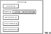
- FIG. 12 illustrates a schematic diagram of a computing device that is configurable for operation of the tissue property sensing device 100 and designated generally as controller 300.
- the controller 300 may represent one or more components of the tissue property sensing device 100 (e.g., an input interface, output interface, or the like).
- the controller 300 may include one or more processors 302, memories 304, input interfaces 310, output interfaces 312, wireless interfaces 314, or any desired subset of components thereof.
- the memory 304 includes non-transitory computer-readable storage media for storing data and/or software which include instructions that may be executed by the one or more processors 302. When executed, the instructions may cause the processor 302 to control operation of the controller 300, e.g., reception and transmission of sensor signals transmitted and received during operation of the one or more sensors "S" disposed along the head 148 of the piston 138 as well as the motor (not explicitly shown) associated with the first drive screw 208 ( FIG. 11 ). More particularly, the controller 300 may receive the sensor signals, indicative of one or more light amplitude measurements, and store the sensor signals in the memory 304 of the controller 300.
- the sensor signals indicative of the light amplitude measurements may be stored with supplemental information including, but not limited to, time stamp information associated with the reception of the signals, device information associated with the device receiving the sensor signals (e.g., encoder measurements), and the like.
- the memory 304 includes non-transitory computer-readable storage media for storing data and/or software which includes instructions that may be executed by the one or more processors 302.
- the memory 304 may include one or more solid-state storage devices such as flash memory chips. Additionally, or alternatively, the memory 304 may include one or more mass storage devices in communication with the processor 302 through a mass storage controller and a communications bus (not shown).
- computer-readable media may include any available media that can be accessed by a processor 302. More particularly, computer readable storage media may include, without limitation, non-transitory, volatile, non-volatile, removable, non-removable media, and the like, implemented in any method of technology for storage of information such as computer readable instructions, data structures, program modules, or other suitable data access and management systems.
- Examples of computer-readable storage media include RAM, ROM, EPROM, EEPROM, flash memory, or other known solid state memory technology, CD-ROM, DVD, Blu-Ray, or other such optical storage, magnetic cassettes, magnetic tape, magnetic disk storage or other magnetic storage devices, or any other medium which may be used to store information and which can be accessed by the controller 300.
- the memory 304 stores data 306 and/or one or more applications 308.
- Such applications 308 may include instructions which are executed on the one or more processors 302 of the controller 300.
- the applications 308 may include instructions which cause an input interface 310 and/or an output interface 312 to receive and transmit sensor signals, respectively, to and from the tissue property sensing device 100 and/or the handheld device 200. More particularly, as the at least one sensor "S" (see FIG. 1 ) senses one or more of the tissue properties discussed above, the at least one sensor "S” may, in response, transmit signals indicative of the measurements to the input interface 310. Once received by the input interface 310, the signals transmitted by the one or more sensors "S" may be stored in the at least one memory 304 of the controller 300.
- the controller 300 may transmit the signals for analysis and/or display via the output interface 312.
- the output interface 312 may transmit the sensor signals to a display device (not explicitly shown) either disposed on the tissue property sensing device 100, the handheld device 200, or a display located remotely relative to the tissue property sensing device 100.
- the memory 304 may further transmit and/or receive data via a wireless interface 314 via one or more wireless configurations, e.g., radio frequency, optical, Wi-Fi, Bluetooth (an open wireless protocol for exchanging data over short distances, using short length radio waves, from fixed and mobile devices, creating personal area networks (PANs), ZigBee® (a specification for a suite of high level communication protocols using small, low-power digital radios based on the IEEE 802.15.4-2003 standard for wireless personal area networks (WPANs)).
- PANs personal area networks
- ZigBee® a specification for a suite of high level communication protocols using small, low-power digital radios based on the IEEE 802.15.4-2003 standard for wireless personal area networks (WPANs)
- WPANs wireless personal area networks
- the wireless interface 314 may be integrated into the input interface 310 and/or the output interface 312.
- process 400 a flow diagram associated with a method of measuring one or more tissue properties with a tissue property sensing device is illustrated and referred to generally as process 400.
- the tissue property sensing device 100 is engaged by a clinician or by default instructions stored in the memory 304 to transition the tissue property sensing device 100 to an open configuration (block 402; see FIG. 5 ). This can take place prior to or after insertion of the tissue property sensing device 100 into a patient.
- the clinician may engage one or more input buttons (not explicitly labeled) on the handheld device 200.
- the controller 300 may receive and analyze the signal and, based on the analysis, cause the motor of the handheld device 200 to engage the one or more proximal connector sleeves 108 by rotating the one or more drive screws 208. Once the piston is advanced to a desired position ( FIG.
- the handheld device 200 stops the drive screw 208 from rotating further.
- the memory 304 may cause the tissue property sensing device 100 to transition to the closed configuration prior to insertion of the distal portion of the tissue property sensing device 100 into the body of the patient. This may be done to collapse or otherwise prevent the piston from engaging or catching tissue during the insertion process, as well as for calibration of the tissue property sensing device 100 (e.g., to zero or otherwise initialize initial position measurements collected from the one or more encoders disposed about the tissue property sensing device 100).
- the target tissue "T" is positioned between the head 148 of the piston 138 and the head 152 of the anvil 150 (block 404).
- the clinician engages the handheld device 200 to cause the sensing assembly to transition to an approximated configuration (see FIG. 7 ) (block 406).
- the clinician engages one or more buttons on the handheld device 200 to cause the piston 138 to retract to a proximal-most position.
- the controller 300 may receive sensor measurements from the one or more encoders to determine the position of the piston 138 relative to the center drive 124 (e.g., the components associated with the one or more encoders that remain stationary as the center drive 124, and by extension the piston 138, move proximally or distally).
- the controller 300 determines that the piston 138 is not in a retracted position (block 408), the controller 300 continues to cause the piston 138 to move proximally to compress the tissue "T". Otherwise, once the controller 300 determines that the piston 138 is in a retracted position, the controller 300 prepares for a tissue property sensing phase.
- the retracted position may be any predetermined position or range of positions of the piston 138 and/or the center drive 124 relative to a fixed component of the tissue property sensing device (e.g., the inner shaft "IS” or outer shaft “OS”) and may vary depending upon the thickness of the tissue "T".
- a fixed component of the tissue property sensing device e.g., the inner shaft "IS” or outer shaft “OS”
- the tissue "T" thickness may be determined.
- a clinician may view the plurality of indicators 142 through the window 162 in the outer shaft "OS" and, based on the visible indicators, determine the thickness of the tissue between the head 148 of the piston 138 and the head 152 of the anvil 150.
- the controller 300 may determine the tissue thickness based on measurements received by the one or more encoders disposed about the tissue property sensing device 100. In addition to the tissue thickness, an initial pressure exerted by the sensing assembly onto the target tissue "T" may be determined.
- the controller 300 may determine the initial pressure exerted by the sensing assembly when the tissue property sensing device 100 is in the approximated configuration.
- the tension spring 160 may be selected such that, when in the approximated configuration, the sensing assembly applies a pressure known to occlude blood flow with the tissue "T". Confirmation of blood flow occlusion may be determined by the controller 300 based on one or more sensor measurements measured by the sensor "S" (e.g., one or more light amplitude measurements being within a predetermined range).
- the controller 300 may cause the motor of the handheld device 200 to rotate the one or more drive screws 208 to cause the center drive 124 to move distally toward the intermediate position until blood within the tissue begins to flow (block 410; see FIG. 9 ). Based on the measured distance which the piston 138 and/or the center drive 124 moved distal relative to one or more fixed components of the tissue property sensing device 100, the spring constant of the tension spring 160, and the surface area of the head 148 of the piston 138 and the head 152 of the anvil 150, the controller 300 determines the pressure exerted on the target tissue "T" by the sensing assembly (block 414) when blood within the tissue begins to flow again. Based upon this determination, blood pressure can be determined.
- the controller 300 determines that the blood flow of the target tissue "T” is still completely occluded (“YES” at block 416) (e.g., no light amplitude measurements sensed by the sensor "S” exceed a predetermined measurement) the center drive 124 is moved distally (block 410) until blood begins to flow again in the tissue "T".
- the tissue property sensing device 100 may move the center drive 124, and by extension the piston 138, to determine the diastolic pressure of the patient at the target tissue.
- the controller 300 continues to cause the center drive 124 and the piston 138 to advance until blood flow is fully restored within the tissue "T" (block 420). When this occurs, the pressure exerted on the target tissue "T" may be determined as described above.
- This pressure corresponds to the diastolic blood pressure of the patient taken at the target tissue (e.g., the light amplitude measurements may consistently be greater than a predetermined light amplitude measurement threshold, indicating that blood flow has completely returned to the target tissue (block 428)).
- the controller 300 may transition the tissue property sensing device 100 toward the open configuration. This may be achieved by engaging the motor of the handheld device 200 to rotate the one or more drive screws 208 and advance the center drive 124 to a proximal-most position (e.g., the open configuration). Once the tissue is removed from the sensing assembly, the tissue property sensing device 100 may be positioned about target tissue, with process 400 repeated to determine the systolic and/or diastolic pressure at that target tissue.
- the tissue property sensing device 100 may be transitioned to the approximated configuration for removal.
- the controller 300 may cause the motor of the handheld device 200 to rotatably engage the proximal connector sleeve 108, thereby causing the center drive to move proximally.
- the controller 300 may receive manual input from the clinician (e.g., by determining one or more input buttons are engaged) and in response engage the motor. Once the head 148 of the piston 138 is flush with the head 152 of the anvil 150, the tissue property sensing device 100 may be removed from the patient.
- the sensors may be disposed on any suitable portion of the robotic arm. Therefore, the above description should not be construed as limiting, but merely as exemplifications of various embodiments. Those skilled in the art will envision other modifications within the scope and spirit of the claims appended thereto.
Landscapes
- Health & Medical Sciences (AREA)
- Life Sciences & Earth Sciences (AREA)
- Engineering & Computer Science (AREA)
- Veterinary Medicine (AREA)
- General Health & Medical Sciences (AREA)
- Biophysics (AREA)
- Biomedical Technology (AREA)
- Heart & Thoracic Surgery (AREA)
- Medical Informatics (AREA)
- Molecular Biology (AREA)
- Surgery (AREA)
- Animal Behavior & Ethology (AREA)
- Pathology (AREA)
- Public Health (AREA)
- Physics & Mathematics (AREA)
- Cardiology (AREA)
- Physiology (AREA)
- Vascular Medicine (AREA)
- Ophthalmology & Optometry (AREA)
- Dentistry (AREA)
- Oral & Maxillofacial Surgery (AREA)
- Computer Networks & Wireless Communication (AREA)
- Endocrinology (AREA)
- Gastroenterology & Hepatology (AREA)
- Hematology (AREA)
- Measuring Pulse, Heart Rate, Blood Pressure Or Blood Flow (AREA)
- Measuring And Recording Apparatus For Diagnosis (AREA)
- Surgical Instruments (AREA)
Abstract
Description
- This application claims the benefit of and priority to
U.S. Provisional Patent Application Serial No. 62/878,816 filed July 26, 2019 - The present disclosure is directed to systems and methods for measuring tissue properties and, more particularly, to systems and methods for occluding blood flow in target tissue during minimally-invasive surgeries to measure tissue properties.
- During surgical procedures medical professionals or clinicians may find it desirable to determine one or more tissue properties prior to acting upon the tissue. For example, during colorectal surgeries which require anastomosis, the clinician visually inspects the tissue of the colon to be resected. Typically, during inspection, the clinician visually observes the colon and determines which portion or portions of the colon are diseased. The clinician then identifies which diseased portions of the colon will be removed. Observation may be performed via one or more imaging devices positioned within the colon or proximate to the colon. Various other surgical procedures require similar visual inspection of tissue to determine which portions of tissue are to be removed.
- Depending on the procedure and the tissue being examined, the clinician may not be able to identify all areas of concern due to the limited visibility of the clinician. For example, referring again to anastomotic procedures, the colon may include an abnormal growth which may not be easily visualized from an inspection of the exterior of the colon. As such, the clinician may need to inspect the interior of the tissue to be resected as well. Inspection of the interior of the colon may require additional clinicians and/or imaging or visualization devices, e.g., endoscopes, to assist in imaging the interior of the colon. Care must be taken when aligning the interior and exterior views during the imaging process.
- As such, improved devices and methods for evaluating tissue properties during a surgical procedure are desirable.
- One aspect of the present disclosure is directed to a tissue property sensing system including an adapter assembly having a drive interface, a drive screw, and a sensing assembly. The drive screw is coupled to the drive interface of the adapter assembly and extends from the adapter assembly. The sensing assembly is movable along the drive screw and includes an outer shaft, an anvil, a center drive, a piston, and a tension spring. The anvil is supported on a distal portion of the outer shaft. The center drive is movable within the outer shaft and defines a longitudinal bore. The piston includes a distal arm having a distal portion, and a head that extends from the distal portion of the distal arm. The piston is movable within the outer shaft to move the head in relation to the anvil between an open configuration and a closed configuration, wherein in the closed configuration, the head of the piston and the anvil are positioned to clamp and occlude flow of blood within tissue. The tension spring is coupled to the center drive and to the piston to urge the piston towards the center drive and to urge the head of the piston towards the anvil.
- In embodiments, the head of the piston supports at least one sensor.
- In some embodiments, the piston includes a proximal arm and the center drive includes a housing, wherein the proximal arm is received within the housing to prevent rotatable movement of the piston in relation to the center drive.
- In certain embodiments, the center drive includes a threaded opening, and a portion of the drive screw is received within the threaded opening such that rotation of the drive screw in relation to the center drive causes longitudinal movement of the center drive within the outer shaft.
- In embodiments, rotation of the drive screw in a first direction causes the center drive to move distally in relation to the adapter assembly and rotation of the drive screw in a second direction causes the center drive to move proximally in relation to the adapter assembly.
- In some embodiments, in the closed configuration, the sensing assembly applies a predetermined range of forces to tissue disposed within the sensing assembly.
- In certain embodiments, the outer shaft defines a window and the proximal arm of the piston supports a plurality of indicators, wherein one or more of the plurality indicators is visible through the window in the closed configuration to indicate a thickness of the tissue positioned between the head of the piston and the anvil.
- In embodiments, a sensor is disposed on one of the head of the piston or the anvil.
- In some embodiments, the center drive supports a fixation pin that is disposed within the longitudinal bore and the tension spring is coupled to the fixation pin.
- Another aspect of the present disclosure is directed to a method of sensing blood pressure within a tissue property sensing device, wherein the method includes positioning tissue between a head of a piston and an anvil which are coupled together via a spring having a known spring constant; occluding a flow of blood within the tissue by moving the head of the piston and the anvil of the tissue property sensing device to a closed configuration and increasing tension in the tension spring; moving the head of the piston away from the anvil to reduce pressure exerted on the target tissue to allow the blood to begin to flow again within the tissue; and calculating a systolic blood pressure of a patient taken at the tissue when the blood within the target tissue begins to flow again.
- In embodiments, after determining the systolic blood pressure of the patient, the method includes moving the head of the piston further away from the anvil so that the flow of blood within the tissue is not occluded; and calculating a diastolic blood pressure of the patient taken at the tissue when it is determined that flow of blood within the target tissue is not occluded.
- In some embodiments, determining the systolic blood pressure includes determining a position of the head of the piston relative to a fixed component of the tissue property sensing device when the blood begins to flow again within the tissue, calculating a length of the spring based on the determined position; and based on the length of the spring, calculating a force exerted by the spring on the tissue.
- In embodiments, determining the diastolic blood pressure includes determining a position of the head of the piston relative to a fixed component of the tissue property sensing device in response to determining that blood flow is no longer occluded in the tissue, calculating a length of the spring based on the determined position, and based on the length of the spring, calculating a force exerted by the spring on the tissue.
- Various embodiments of the disclosed systems and methods are described herein below with reference to the drawings, wherein:
-
FIG. 1 is a side perspective view of a tissue property sensing device with a sensing assembly in an open configuration, according to exemplary embodiments of the present disclosure; -
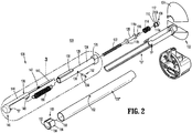
FIG. 2 is a side perspective view of the tissue property sensing device ofFIG. 1 with parts separated; -
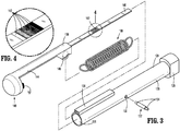
FIG. 3 is an enlarged view of the indicated area of detail ofFIG. 1 ; -
FIG. 4 is an enlarged view of the indicated area of detail shown inFIG. 3 ; -
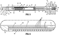
FIG. 5 is a cross-sectional view taken along section line 5-5 of the tissue property sensing device ofFIG. 1 in an open configuration; -
FIG. 6 is an enlarged view of the indicated area of detail ofFIG. 5 ; -
FIG. 7 is a cross-sectional view taken along line 5-5 of the tissue property sensing device ofFIG. 1 in an approximated configuration; -
FIG. 8 is an enlarged view of the indicated area of detail ofFIG. 7 ; -
FIG. 9 is a cross-sectional view taken along line 5-5 of the tissue property sensing device ofFIG. 1 in a partially-approximated configuration; -
FIG. 10 is an enlarged view of the indicated area of detail ofFIG. 9 ; -
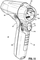
FIG. 11 is a perspective view of a handle assembly for connection with the tissue property sensing device ofFIG. 1 ; -
FIG. 12 is a schematic block diagram of a computing device that may be employed according to various embodiments of the present disclosure; and -
FIG. 13A illustrates a flow diagram of a process for controlling of the tissue property sensing device ofFIG. 1 , according to embodiments of the present disclosure. - The disclosed tissue property sensing device will now be described in detail with reference to the drawings. It will be understood that like reference numerals may designate identical or corresponding elements in each of the several views. As used herein, the term "proximal" generally refers to that portion of the described element or feature which is closer to a clinician, while the term "distal" generally refers to that portion of the described element or feature which is farther from the clinician; the term "clinician" generally refers to medical personnel including doctors, surgeons, nurses, support personal, and the like; and directional terms such as front, rear, upper, lower, top, bottom, distal, proximal, and similar terms are used to assist in understanding the description and are not intended to limit the present disclosure.
- Referring now to
FIGS. 1-4 , an embodiment of a tissue property sensing device is designated generally as tissueproperty sensing device 100. The tissueproperty sensing device 100 includes anadapter assembly 102 that is configured to couple to remote devices such as, for example, a handheld device 200 (FIG. 11 ) or a robotic surgical system (not shown). For purposes of clarity, reference will be made generally to connection and operation of the tissueproperty sensing device 100 to the handheld device 200 (FIG. 11 ), though it will be understood that connection and operation may similarly be made to a robotic surgical system. Examples of such systems may be found by reference toU.S. Patent Application Publication No. 2015/0157320 to Zergiebel et al., filed on November 21, 2014 , nowU.S. Patent No. 9,918,713 U.S. Patent Application Publication No. 2016/0310134 to Contini et al., filed on April 12, 2016 , entitled "HANDHELD ELECTROMECHANICAL SURGICAL SYSTEM," andU.S. Patent No. 8,828,023 , the entire contents of each of which are hereby incorporated by reference in their entirety. Although the handheld device 200 (FIG. 11 ) is illustrated as an electrically powered device, it is envisioned that manually powered handheld devices may also be provided to drive the tissueproperty sensing device 100. - Referring to
FIGS. 2 and5 , theadapter assembly 102 includes an adapter interface having one or more proximal connector sleeves 108 (FIG. 5 ) configured to receive one or more drive screws 208 (FIG. 11 ) that extend from the handheld device 200 (seeFIG. 11 ). In response to engagement of a motor (e.g., a motor of thehandheld device 200 or a robotic surgical system, not explicitly shown), thedrive screw 208 rotates theproximal connector sleeve 108 either clockwise or counter-clockwise. Theproximal connector sleeve 108 may be operably coupled to adrive interface 106, and it will be understood that in embodiments (as shown inFIG. 2 ) both theproximal connector sleeve 108 and thedrive interface 106 may be integrally formed and/or may be the same component. For a detailed description of the operation and engagement of an adapter (e.g., adapter assembly 102) by ahandheld device 200, reference may be made toU.S. Provisional Patent Application No. 62/597,595 - The
drive interface 106 includes aflange 112 extending around a periphery of thedrive interface 106. Theflange 112 is configured to engage a proximal portion of acompression spring 114, and receive longitudinal forces exerted from thecompression spring 114 to urge thedrive interface 106 proximally in a cavity "C" (FIG. 5 ) of thehousing 104 of theadapter assembly 102. Thedrive interface 106 further includes adistal connector sleeve 110 that defines a corresponding recess extending inwardly from a distal portion of thedrive interface 106 proximally. Theproximal connector sleeve 108 and thedistal connector sleeve 110 are configured to receive the drive screw 208 (FIG. 11 ) and adrive head 116, respectively. In embodiments, when rotatably coupled to the one or more drive screws 208 (FIG. 11 ), thedrive interface 106 may be engaged or disengaged by advancing the one or more drive screws 208 of thehandheld device 200 distal or proximal relative to theproximal connector sleeve 108. Such distal and proximal advancement of the one or more drive screws 208 either causes thecompression spring 114 to compress or decompress, in turn causing a proximal portion of thedrive head 116 to enter or exit thedistal connector sleeve 110 of thedrive interface 106. The distal portion of thedrive screw 208 has a configuration (e.g., a flat head, a Phillips head, a Torx head, etc.) that corresponds to the configuration of the recess defined by theproximal connector sleeve 108. Similarly, the proximal portion of thedrive head 116 has a configuration that corresponds to arecess 110a defined by theproximal connector sleeve 108. Thedrive head 116 extends distally to form adrive screw shaft 120. In embodiments, thedrive screw shaft 120 has aproximal flange 118a and adistal flange 118b that are spaced from each other and extend about thedrive screw shaft 120. Theproximal flange 118a may be configured to be received in a corresponding channel defined by thehousing 104 of the adapter (not explicitly shown), and thedistal flange 118b may be disposed about thedrive screw shaft 120 and configured to be received in a separate corresponding channel (seeFIG. 5 ) of thehousing 104 of theadapter assembly 102 to longitudinally fix thedrive screw shaft 120 in relation to thehousing 104. Thedrive screw shaft 120 further includesthreads 122 disposed about a distal portion thereof. Thethreads 122 are configured to rotatably engage corresponding threading defined within a threaded opening of the center drive 124 to cause the center drive 124 to move either proximally or distally when rotated in a first or second direction, respectively. It is contemplated that thedrive screw shaft 120 may be formed of any desired metal, plastic, composite, alloy, etc., and in embodiments, may be made of lead. - Referring to
FIGS. 3 and 4 , thecenter drive 124 includes abase 126 and adrive housing 128 that extends distal from thebase 126. Thebase 126 and drivehousing 128 define a through bore "B". The through bore "B" is defined by aninner surface 131 that includes a threaded portion 127 that is configured to be rotatably engaged by thethreads 122 of thedrive screw shaft 120. In embodiments, the threaded portion 127 of the center drive 124 (FIG. 6 ) may extend along any portion or portions between the proximal and distal portions of thecenter drive 124. Thedrive housing 128 defines a pair of apertures 130 (FIG. 2 ) configured to receive a portion of afixation pin 132. Specifically, thefixation pin 132 may include spring-loaded and outward biasedfixation members 134 disposed within a housing of thefixation pin 132. Thefixation members 134 may be advanced inward relative to the housing of thefixation pin 132 prior to insertion of thefixation pin 132 within the lumen of thedrive housing 128. Thefixation pin 132 may subsequently be aligned with the pair ofapertures 130, thereby allowing thefixation members 134 to be move outward and through the pair ofapertures 130 to secure thefixation pin 132 within thecenter drive 124. - The
center drive 124 further includes apiston arm housing 136 configured to receive a portion of aproximal piston arm 140 to maintain the angular position of thepiston 138 relative to the center drive 124 (e.g., to prevent rotation of thepiston 138 relative to the center drive 124). In embodiments (as shown inFIG. 2 ), thefixation members 134 of thefixation pin 132 may extend outward and be configured to slide along a pin window "P" (FIG. 2 ) defined at least in part by an inner shaft "IS", thereby limiting rotational movement of the center drive 124 relative to the inner shaft "IS". - With continued reference to
FIGS. 1-4 , and with particular reference toFIGS. 3 and 4 , a sensing assembly includes thecenter drive 124, apiston 138, and atension spring 160 that is positioned to exert force on both thecenter drive 124 and thepiston 138 to urge them toward an approximated configuration (FIG. 9 .) Thepiston 138 includes aproximal piston arm 140 and adistal piston arm 144 that extends away from theproximal piston arm 140. Theproximal piston arm 140 has a substantially rectangular cross-section, as well as a plurality ofindicators 142 disposed along a top portion thereof. The plurality ofindicators 142 are configured to be viewed through awindow 162 of an outer shaft "OS" (FIG. 2 ) of the tissueproperty sensing device 100. Thedistal piston arm 144 of thepiston 138 has a housing which defines an aperture 146 (FIG. 4 ) located along a proximal portion of thedistal piston arm 144. Theaperture 146 is configured to receive a distal portion of thetension spring 160. Thedistal piston arm 144 includes ahead 148 that extends inwardly therefrom. In embodiments, thehead 148 may be shaped to correspond to the shape of ahead 152 of ananvil 150 that is coupled to the outer shaft "OS" of the tissueproperty sensing device 100. In embodiments, thehead 148 of thedistal piston arm 144 may support one or more sensors "S" such as, for example, piezoresistive force sensors, optical sensors, impedance sensors, and the like. For a detailed discussion of sensors used in connection with a tissue property sensing device, and sensing systems more generally, reference may be made toU.S. Provisional Patent Application Publication No.: 62/661,821 to Eschbach - With continued reference to
FIG. 2 , theanvil 150 is inserted into an opening defined by a distal portion of the outer shaft "OS" of the tissueproperty sensing device 100. More particularly, theanvil 150 is fixed along the interior of the outer shaft "OS" by any suitable means such as, without limitation, a friction fit, adhesives, crimps, welds, or other known coupling techniques. Theanvil 150 defines thehead 152 and includes aflange 154 that extends from aperiphery wall 156 of theanvil 150 proximally relative to thehead 152. Theflange 154 limits proximal movement of theanvil 150 into the outer shaft "OS" of the tissueproperty sensing device 100 to allow theanvil 150 to receive and compress target tissue thereon, while transferring forces received by thehead 152 to the outer shaft "OS". Thehead 152 of theanvil 150 further includes achannel 158 that is configured to slidably receive theproximal piston arm 140 of thepiston 138 therethrough, thereby allowing theproximal piston arm 140 to be inserted into thepiston arm housing 136 of thecenter drive 124 when theanvil 150 is coupled to the outer shaft "OS". Thechannel 158 is in part formed by an opening in theflange 154 of theanvil 150. It will be understood that, in embodiments, one or more sensors (not explicitly shown) may be disposed in or on thehead 152 of theanvil 150, similar to sensors "S" disposed in or on thehead 148 of thepiston 138. - The
drive screw shaft 120,center drive 124, or any other component operably coupled thereto, may be coupled to one or more encoders (not explicitly shown) such as longitudinal or rotational encoders that are disposed along the inner shaft "IS" and/or the outer shaft "OS". The encoders may be in electrical communication (e.g., wired and/or wireless communication) with acontroller 300 further described with respect toFIG. 12 . The encoders may transmit position data received indicative of either longitudinal or rotational distances traveled by thedrive screw shaft 120 and/or thecenter drive 124. In embodiments, a longitudinal encoder (not explicitly shown) may be coupled to thecenter drive 124, an interior portion of the outer shaft "OS", and/or various parts of thepiston 138 to measure longitudinal motion of thepiston 138 relative to the tissueproperty sensing device 100. -
FIGS. 5 and 6 illustrate the tissueproperty sensing device 100 in an open configuration. To transition the tissueproperty sensing device 100 to the open configuration, thedrive screw shaft 120 is rotated in a first direction (e.g., either clockwise or counter-clockwise), thereby causing thethreads 122 of thedrive screw shaft 120 to apply a force on the threads of thecenter drive 124 and cause the center drive 124 to advance along thedrive screw shaft 120 within the outer shaft "OS". As the center drive 124 advances, the center drive 124 contacts thedistal piston arm 144 and advances thepiston 138 such that thehead 148 of thepiston 138 and theanvil 150 are moved to an open position in spaced relation to each other. Once thepiston 138 is moved away from theanvil 150, target tissue (e.g., a portion of the intestines or other tissue located inside the body of a patient) may be positioned between the proximal portion of thehead 148 and theanvil 150. As thepiston 138 moves within the outer shaft "OS", theindicators 142 are moved out of alignment with thewindow 162 of the outer shaft "OS". -
FIGS. 7 and 8 illustrate the tissueproperty sensing device 100 in an approximated configuration. To transition the tissueproperty sensing device 100 to the approximated configuration thedrive screw shaft 120 is rotated in a second direction different from the first direction, causing thethreads 122 of thedrive screw shaft 120 to apply a force onto the threads of thecenter drive 124 and cause the center drive 124 to retract within the outer shaft "OS" relative to thedrive screw shaft 120. Once retracted, thetension spring 160 exerts a known force proximal to and onto thepiston 138. In response to pulling of the center drive 124 on thetension spring 160, thetension spring 160 applies forces proximally and distally to urge thepiston 138 and the inner shaft "IS", respectively, toward one another. As shown inFIG. 8 , in embodiments theindicators 142 may become visible once thecenter drive 124 is advanced proximally beyond a predetermined position. Based on the position of thepiston 138 relative to the position of thecenter drive 124, a distance by which thetension spring 160 is expanded may be calculated. The tension exerted by thetension spring 160 may subsequently be calculated based on a known spring constant associated with thetension spring 160 and the expanded distance. In embodiments, the compressive force on tissue compressed between theanvil 150 and thehead 148 of thepiston 138 may further be determined by dividing the calculated tension in thespring 160 by the area formed by a compressive surface of theanvil 150. - Referring now to
FIGS. 9 and 10 , the tissueproperty sensing device 100 is shown in an intermediate configuration. To transition the tissueproperty sensing device 100 to the intermediate configuration, thedrive screw shaft 120 is rotated in the first direction, advancing thecenter drive 124 within the outer shaft "OS".FIG. 11 illustrates a handheld device that is configured to connect to the tissue property sensing device 100 (FIG. 1 ) and is designated generally as 200. Thehandheld device 200 includes ahousing 202 having ahandle portion 202a, and a connectingportion 202b. The connectingportion 202b is configured to selectively couple to theadapter assembly 102. More specifically, the connectingportion 202b has arecess 204 which extends proximally inward to a proximal connectingsurface 206. The connectingportion 202b ofhandheld device 200 further includeselectrical contacts 212 extending distally from the proximal connectingsurface 206 and configured to mate with electrical contacts (not explicitly shown) located on theadapter assembly 102. The connectingportion 202b ofhandheld device 200 includes the drive screws 208 which are configured to rotate and mate with the one or moreproximal connector sleeves 108 located on theadapter assembly 102 as described above. When theelectrical contacts 212 are operably coupled to thehousing 104 of the tissueproperty sensing device 100, theelectrical contacts 212 are configured to transmit electrical signals to and from components of the tissueproperty sensing device 100 including the one or more sensors "S" disposed along thehead 148 of thepiston 138, and the one or more encoders (not explicitly shown) disposed along the various components of the tissueproperty sensing device 100. For a detailed description of a handheld device, reference may be made toU.S. Patent Application Publication No. 2016/0310134, filed on April 12, 2016 , entitled "HANDHELD ELECTROMECHANICAL SURGICAL SYSTEM", the contents of which are hereby incorporated by reference in their entirety. -
FIG. 12 illustrates a schematic diagram of a computing device that is configurable for operation of the tissueproperty sensing device 100 and designated generally ascontroller 300. Though not explicitly shown in figures of the present application, thecontroller 300, or one or more components thereof, may represent one or more components of the tissue property sensing device 100 (e.g., an input interface, output interface, or the like). In addition, thecontroller 300 may include one ormore processors 302,memories 304, input interfaces 310,output interfaces 312, wireless interfaces 314, or any desired subset of components thereof. - The
memory 304 includes non-transitory computer-readable storage media for storing data and/or software which include instructions that may be executed by the one ormore processors 302. When executed, the instructions may cause theprocessor 302 to control operation of thecontroller 300, e.g., reception and transmission of sensor signals transmitted and received during operation of the one or more sensors "S" disposed along thehead 148 of thepiston 138 as well as the motor (not explicitly shown) associated with the first drive screw 208 (FIG. 11 ). More particularly, thecontroller 300 may receive the sensor signals, indicative of one or more light amplitude measurements, and store the sensor signals in thememory 304 of thecontroller 300. The sensor signals indicative of the light amplitude measurements may be stored with supplemental information including, but not limited to, time stamp information associated with the reception of the signals, device information associated with the device receiving the sensor signals (e.g., encoder measurements), and the like. In embodiments, thememory 304 includes non-transitory computer-readable storage media for storing data and/or software which includes instructions that may be executed by the one ormore processors 302. Thememory 304 may include one or more solid-state storage devices such as flash memory chips. Additionally, or alternatively, thememory 304 may include one or more mass storage devices in communication with theprocessor 302 through a mass storage controller and a communications bus (not shown). Although the description of computer readable media described in this disclosure refers to a solid-state storage device, it will be appreciated by one of ordinary skill that computer-readable media may include any available media that can be accessed by aprocessor 302. More particularly, computer readable storage media may include, without limitation, non-transitory, volatile, non-volatile, removable, non-removable media, and the like, implemented in any method of technology for storage of information such as computer readable instructions, data structures, program modules, or other suitable data access and management systems. Examples of computer-readable storage media include RAM, ROM, EPROM, EEPROM, flash memory, or other known solid state memory technology, CD-ROM, DVD, Blu-Ray, or other such optical storage, magnetic cassettes, magnetic tape, magnetic disk storage or other magnetic storage devices, or any other medium which may be used to store information and which can be accessed by thecontroller 300. - In embodiments, the
memory 304stores data 306 and/or one ormore applications 308.Such applications 308 may include instructions which are executed on the one ormore processors 302 of thecontroller 300. Theapplications 308 may include instructions which cause aninput interface 310 and/or anoutput interface 312 to receive and transmit sensor signals, respectively, to and from the tissueproperty sensing device 100 and/or thehandheld device 200. More particularly, as the at least one sensor "S" (seeFIG. 1 ) senses one or more of the tissue properties discussed above, the at least one sensor "S" may, in response, transmit signals indicative of the measurements to theinput interface 310. Once received by theinput interface 310, the signals transmitted by the one or more sensors "S" may be stored in the at least onememory 304 of thecontroller 300. Additionally, or alternatively, thecontroller 300 may transmit the signals for analysis and/or display via theoutput interface 312. For example, theoutput interface 312 may transmit the sensor signals to a display device (not explicitly shown) either disposed on the tissueproperty sensing device 100, thehandheld device 200, or a display located remotely relative to the tissueproperty sensing device 100. Thememory 304 may further transmit and/or receive data via awireless interface 314 via one or more wireless configurations, e.g., radio frequency, optical, Wi-Fi, Bluetooth (an open wireless protocol for exchanging data over short distances, using short length radio waves, from fixed and mobile devices, creating personal area networks (PANs), ZigBee® (a specification for a suite of high level communication protocols using small, low-power digital radios based on the IEEE 802.15.4-2003 standard for wireless personal area networks (WPANs)). Although depicted as a separate component, thewireless interface 314 may be integrated into theinput interface 310 and/or theoutput interface 312. - Referring to
FIG. 13A , a flow diagram associated with a method of measuring one or more tissue properties with a tissue property sensing device is illustrated and referred to generally asprocess 400. - Initially, the tissue
property sensing device 100 is engaged by a clinician or by default instructions stored in thememory 304 to transition the tissueproperty sensing device 100 to an open configuration (block 402; seeFIG. 5 ). This can take place prior to or after insertion of the tissueproperty sensing device 100 into a patient. To transition the tissueproperty sensing device 100 to the open configuration, the clinician may engage one or more input buttons (not explicitly labeled) on thehandheld device 200. In response to the input, thecontroller 300 may receive and analyze the signal and, based on the analysis, cause the motor of thehandheld device 200 to engage the one or moreproximal connector sleeves 108 by rotating the one or more drive screws 208. Once the piston is advanced to a desired position (FIG. 5 ) (e.g., to the open configuration) thehandheld device 200 stops thedrive screw 208 from rotating further. It will be understood that, in embodiments, thememory 304 may cause the tissueproperty sensing device 100 to transition to the closed configuration prior to insertion of the distal portion of the tissueproperty sensing device 100 into the body of the patient. This may be done to collapse or otherwise prevent the piston from engaging or catching tissue during the insertion process, as well as for calibration of the tissue property sensing device 100 (e.g., to zero or otherwise initialize initial position measurements collected from the one or more encoders disposed about the tissue property sensing device 100). - Once the tissue
property sensing device 100 is inserted into the patient, the target tissue "T" is positioned between thehead 148 of thepiston 138 and thehead 152 of the anvil 150 (block 404). Next, the clinician engages thehandheld device 200 to cause the sensing assembly to transition to an approximated configuration (seeFIG. 7 ) (block 406). Specifically, the clinician engages one or more buttons on thehandheld device 200 to cause thepiston 138 to retract to a proximal-most position. As thepiston 138 moves proximally, thecontroller 300 may receive sensor measurements from the one or more encoders to determine the position of thepiston 138 relative to the center drive 124 (e.g., the components associated with the one or more encoders that remain stationary as thecenter drive 124, and by extension thepiston 138, move proximally or distally). When thecontroller 300 determines that thepiston 138 is not in a retracted position (block 408), thecontroller 300 continues to cause thepiston 138 to move proximally to compress the tissue "T". Otherwise, once thecontroller 300 determines that thepiston 138 is in a retracted position, thecontroller 300 prepares for a tissue property sensing phase. The retracted position may be any predetermined position or range of positions of thepiston 138 and/or the center drive 124 relative to a fixed component of the tissue property sensing device (e.g., the inner shaft "IS" or outer shaft "OS") and may vary depending upon the thickness of the tissue "T". - Once in the retracted position (e.g., the closed configuration) the tissue "T" thickness may be determined. For example, a clinician may view the plurality of
indicators 142 through thewindow 162 in the outer shaft "OS" and, based on the visible indicators, determine the thickness of the tissue between thehead 148 of thepiston 138 and thehead 152 of theanvil 150. In embodiments, thecontroller 300 may determine the tissue thickness based on measurements received by the one or more encoders disposed about the tissueproperty sensing device 100. In addition to the tissue thickness, an initial pressure exerted by the sensing assembly onto the target tissue "T" may be determined. For example, based on sensor signals received indicating the position of thepiston 138 relative to thecenter drive 124, a known spring constant of thetension spring 160, and the surface area of thehead 148 of thepiston 138 and thehead 152 of theanvil 150, thecontroller 300 may determine the initial pressure exerted by the sensing assembly when the tissueproperty sensing device 100 is in the approximated configuration. It will be understood that thetension spring 160 may be selected such that, when in the approximated configuration, the sensing assembly applies a pressure known to occlude blood flow with the tissue "T". Confirmation of blood flow occlusion may be determined by thecontroller 300 based on one or more sensor measurements measured by the sensor "S" (e.g., one or more light amplitude measurements being within a predetermined range). - To determine a systolic blood pressure, the
controller 300 may cause the motor of thehandheld device 200 to rotate the one or more drive screws 208 to cause the center drive 124 to move distally toward the intermediate position until blood within the tissue begins to flow (block 410; seeFIG. 9 ). Based on the measured distance which thepiston 138 and/or the center drive 124 moved distal relative to one or more fixed components of the tissueproperty sensing device 100, the spring constant of thetension spring 160, and the surface area of thehead 148 of thepiston 138 and thehead 152 of theanvil 150, thecontroller 300 determines the pressure exerted on the target tissue "T" by the sensing assembly (block 414) when blood within the tissue begins to flow again. Based upon this determination, blood pressure can be determined. If thecontroller 300 determines that the blood flow of the target tissue "T" is still completely occluded ("YES" at block 416) (e.g., no light amplitude measurements sensed by the sensor "S" exceed a predetermined measurement) thecenter drive 124 is moved distally (block 410) until blood begins to flow again in the tissue "T". - Similar to blocks 410-416, the tissue
property sensing device 100 may move thecenter drive 124, and by extension thepiston 138, to determine the diastolic pressure of the patient at the target tissue. To measure the diastolic blood pressure after the systolic blood pressure is measured, thecontroller 300 continues to cause thecenter drive 124 and thepiston 138 to advance until blood flow is fully restored within the tissue "T" (block 420). When this occurs, the pressure exerted on the target tissue "T" may be determined as described above. This pressure corresponds to the diastolic blood pressure of the patient taken at the target tissue (e.g., the light amplitude measurements may consistently be greater than a predetermined light amplitude measurement threshold, indicating that blood flow has completely returned to the target tissue (block 428)). - Once the desired blood pressure is determined (systolic, diastolic, or both) the
controller 300 may transition the tissueproperty sensing device 100 toward the open configuration. This may be achieved by engaging the motor of thehandheld device 200 to rotate the one or more drive screws 208 and advance the center drive 124 to a proximal-most position (e.g., the open configuration). Once the tissue is removed from the sensing assembly, the tissueproperty sensing device 100 may be positioned about target tissue, withprocess 400 repeated to determine the systolic and/or diastolic pressure at that target tissue. - In embodiments, where removal of the inserted portion of the tissue
property sensing device 100 from the patient is desired, the tissueproperty sensing device 100 may be transitioned to the approximated configuration for removal. To do so, thecontroller 300 may cause the motor of thehandheld device 200 to rotatably engage theproximal connector sleeve 108, thereby causing the center drive to move proximally. Specifically, thecontroller 300 may receive manual input from the clinician (e.g., by determining one or more input buttons are engaged) and in response engage the motor. Once thehead 148 of thepiston 138 is flush with thehead 152 of theanvil 150, the tissueproperty sensing device 100 may be removed from the patient. - It will be understood that various modifications may be made to the embodiments disclosed herein. In embodiments, the sensors may be disposed on any suitable portion of the robotic arm. Therefore, the above description should not be construed as limiting, but merely as exemplifications of various embodiments. Those skilled in the art will envision other modifications within the scope and spirit of the claims appended thereto.
- The invention may be described by reference to the following numbered paragraphs:-
- 1. A tissue property sensing system, comprising:
- an adapter assembly including a drive interface;
- a drive screw coupled to the drive interface and extending from the adapter assembly; and
- a sensing assembly movable along the drive screw, the sensing assembly including:
- an outer shaft;
- an anvil supported on a distal portion of the outer shaft;
- a center drive movable within the outer shaft and defining a longitudinal bore;
- a piston movable within the outer shaft and including a distal arm having a distal portion, and a head extending from the distal portion of the distal arm, the piston being movable within the outer shaft to move the head in relation to the anvil between an open configuration and a closed configuration, wherein in the closed configuration, the head of the piston and the anvil are positioned to clamp and occlude blood flow in tissue; and
- a tension spring coupled to the center drive and to the piston to urge the piston towards the center drive and to urge the head of the piston towards the anvil.
- 2. The tissue property sensing system according to
paragraph 1, wherein the head of the piston supports at least one sensor. - 3. The tissue property sensing system according to
paragraph 1, wherein the piston includes a proximal arm and the center drive includes a housing, the proximal arm being received within the housing to prevent rotatable movement of the piston in relation to the center drive - 4. The tissue property sensing system according to
paragraph 1, wherein the center drive includes a threaded opening, and a portion of the drive screw is received within the threaded opening such that rotation of the drive screw in relation to the center drive causes longitudinal movement of the center drive within the outer shaft. - 5. The tissue property sensing system according to
paragraph 4, wherein rotation of the drive screw in a first direction causes the center drive to advance distally in relation to the adapter assembly and rotation of the drive screw in a second direction causes the center drive to advance proximally in relation to the adapter assembly. - 6. The tissue property sensing system according to paragraph 2, wherein in the closed configuration, the sensing assembly applies a predetermined range of forces to tissue disposed within the sensing assembly.
- 7. The tissue property sensing system according to
paragraph 3, wherein the outer shaft defines a window and the proximal arm of the piston supports a plurality of indicators, one or more of the plurality indicators being visible through the window in the closed configuration to indicate a thickness of the tissue positioned between the head of the piston and the anvil. - 8. The tissue property sensing system according to
paragraph 1, wherein a sensor is disposed on one of the head of the piston and the anvil. - 9. The tissue property sensing system according to
paragraph 1, wherein the center drive supports a fixation pin that is disposed within the longitudinal bore, the tension spring being coupled to the fixation pin. - 10. A method of sensing blood pressure using a tissue property sensing device, the method comprising:
- positioning tissue between a head of a piston and an anvil which are coupled together via a spring having a known spring constant;
- occluding a flow of blood within the tissue by moving the head of the piston and the anvil of the tissue property sensing device to a closed configuration and increasing tension in the tension spring;
- moving the head of the piston away from the anvil to reduce pressure exerted on the target tissue to allow the blood to begin to flow again within the tissue; and
- calculating a systolic blood pressure of a patient taken at the tissue when the blood within the target tissue begins to flow again.
- 11. The method according to
paragraph 10, further comprising:- after determining the systolic blood pressure of the patient, moving the head of the piston further away from the anvil so that the flow of blood within the tissue is not occluded; and
- calculating a diastolic blood pressure of the patient taken at the tissue when it is determined that flow of blood within the target tissue is not occluded.
- 12. The method according to
paragraph 10, wherein determining the systolic blood pressure includes:- determining a position of the head of the piston relative to a fixed component of the tissue property sensing device when the blood begins to flow again within the tissue;
- calculating a length of the spring based on the determined position; and
- based on the length of the spring, calculating a force exerted by the spring on the tissue.
- 13. The method according to paragraph 11, wherein determining the diastolic blood pressure includes:
- determining a position of the head of the piston relative to a fixed component of the tissue property sensing device in response to determining that blood flow is no longer occluded in the tissue;
- calculating a length of the spring based on the determined position; and
- based on the length of the spring, calculating a force exerted by the spring on the tissue.
Claims (13)
- A tissue property sensing system, comprising:an adapter assembly including a drive interface;a drive screw coupled to the drive interface and extending from the adapter assembly; anda sensing assembly movable along the drive screw, the sensing assembly including:an outer shaft;an anvil supported on a distal portion of the outer shaft;a center drive movable within the outer shaft and defining a longitudinal bore;a piston movable within the outer shaft and including a distal arm having a distal portion, and a head extending from the distal portion of the distal arm, the piston being movable within the outer shaft to move the head in relation to the anvil between an open configuration and a closed configuration, wherein in the closed configuration, the head of the piston and the anvil are positioned to clamp and occlude blood flow in tissue; anda tension spring coupled to the center drive and to the piston to urge the piston towards the center drive and to urge the head of the piston towards the anvil.
- The tissue property sensing system according to claim 1, wherein the head of the piston supports at least one sensor.
- The tissue property sensing system according to claim 1 or claim 2, wherein the piston includes a proximal arm and the center drive includes a housing, the proximal arm being received within the housing to prevent rotatable movement of the piston in relation to the center drive
- The tissue property sensing system according to any preceding claim, wherein the center drive includes a threaded opening, and a portion of the drive screw is received within the threaded opening such that rotation of the drive screw in relation to the center drive causes longitudinal movement of the center drive within the outer shaft.
- The tissue property sensing system according to claim 4, wherein rotation of the drive screw in a first direction causes the center drive to advance distally in relation to the adapter assembly and rotation of the drive screw in a second direction causes the center drive to advance proximally in relation to the adapter assembly.
- The tissue property sensing system according to claim 2, wherein in the closed configuration, the sensing assembly applies a predetermined range of forces to tissue disposed within the sensing assembly.
- The tissue property sensing system according to claim 3, wherein the outer shaft defines a window and the proximal arm of the piston supports a plurality of indicators, one or more of the plurality indicators being visible through the window in the closed configuration to indicate a thickness of the tissue positioned between the head of the piston and the anvil.
- The tissue property sensing system according to any preceding claim, wherein a sensor is disposed on one of the head of the piston and the anvil.
- The tissue property sensing system according to any preceding claim, wherein the center drive supports a fixation pin that is disposed within the longitudinal bore, the tension spring being coupled to the fixation pin.
- A method of sensing blood pressure using a tissue property sensing device, the method comprising:positioning tissue between a head of a piston and an anvil which are coupled together via a spring having a known spring constant;occluding a flow of blood within the tissue by moving the head of the piston and the anvil of the tissue property sensing device to a closed configuration and increasing tension in the tension spring;moving the head of the piston away from the anvil to reduce pressure exerted on the target tissue to allow the blood to begin to flow again within the tissue; andcalculating a systolic blood pressure of a patient taken at the tissue when the blood within the target tissue begins to flow again.
- The method according to claim 10, further comprising:after determining the systolic blood pressure of the patient, moving the head of the piston further away from the anvil so that the flow of blood within the tissue is not occluded; andcalculating a diastolic blood pressure of the patient taken at the tissue when it is determined that flow of blood within the target tissue is not occluded.
- The method according to claim 10 or claim 11, wherein determining the systolic blood pressure includes:determining a position of the head of the piston relative to a fixed component of the tissue property sensing device when the blood begins to flow again within the tissue;calculating a length of the spring based on the determined position; andbased on the length of the spring, calculating a force exerted by the spring on the tissue.
- The method according to claim 11, wherein determining the diastolic blood pressure includes:determining a position of the head of the piston relative to a fixed component of the tissue property sensing device in response to determining that blood flow is no longer occluded in the tissue;calculating a length of the spring based on the determined position; andbased on the length of the spring, calculating a force exerted by the spring on the tissue.
Applications Claiming Priority (2)
| Application Number | Priority Date | Filing Date | Title |
|---|---|---|---|
| US201962878816P | 2019-07-26 | 2019-07-26 | |
| US16/890,259 US11877833B2 (en) | 2019-07-26 | 2020-06-02 | Systems and methods for monitoring blood pressure with a powered linear drive |
Publications (2)
| Publication Number | Publication Date |
|---|---|
| EP3769672A1 true EP3769672A1 (en) | 2021-01-27 |
| EP3769672B1 EP3769672B1 (en) | 2023-12-06 |
Family
ID=71783854
Family Applications (1)
| Application Number | Title | Priority Date | Filing Date |
|---|---|---|---|
| EP20187314.8A Active EP3769672B1 (en) | 2019-07-26 | 2020-07-23 | Systems for monitoring blood pressure with a powered linear drive |
Country Status (3)
| Country | Link |
|---|---|
| US (1) | US11877833B2 (en) |
| EP (1) | EP3769672B1 (en) |
| CN (1) | CN112294285B (en) |
Citations (7)
| Publication number | Priority date | Publication date | Assignee | Title |
|---|---|---|---|---|
| EP1974676A1 (en) * | 2007-03-28 | 2008-10-01 | Ethicon Endo-Surgery, Inc. | Laparoscopic tissue thickness and clamp load measuring devices |
| US8828023B2 (en) | 2010-11-08 | 2014-09-09 | Kuka Laboratories Gmbh | Medical workstation |
| US20150066000A1 (en) * | 2012-03-06 | 2015-03-05 | Briteseed Llc | Surgical Tool With Integrated Sensor |
| US20150157320A1 (en) | 2013-12-09 | 2015-06-11 | Covidien Lp | Adapter assembly for interconnecting electromechanical surgical devices and surgical loading units, and surgical systems thereof |
| US20160310134A1 (en) | 2015-04-22 | 2016-10-27 | Covidien Lp | Handheld electromechanical surgical system |
| US20190175215A1 (en) * | 2017-12-12 | 2019-06-13 | Covidien Lp | Surgical instruments including devices for sensing tissue properties and methods thereof |
| US20190175216A1 (en) * | 2017-12-12 | 2019-06-13 | Covidien Lp | Surgical instrument including system for sensing tissue properties and methods thereof |
Family Cites Families (35)
| Publication number | Priority date | Publication date | Assignee | Title |
|---|---|---|---|---|
| US4233743A (en) * | 1977-02-03 | 1980-11-18 | Health & Education Services Corporation | Skin-fold caliper |
| US4109647A (en) | 1977-03-16 | 1978-08-29 | The United States Of America As Represented By The Secretary Of The Department Of Health, Education And Welfare | Method of and apparatus for measurement of blood flow using coherent light |
| AU608807B2 (en) | 1987-03-03 | 1991-04-18 | Hitoshi Fujii | Apparatus for monitoring bloodstream |
| US5383880A (en) | 1992-01-17 | 1995-01-24 | Ethicon, Inc. | Endoscopic surgical system with sensing means |
| US5772597A (en) | 1992-09-14 | 1998-06-30 | Sextant Medical Corporation | Surgical tool end effector |
| CA2124109A1 (en) | 1993-05-24 | 1994-11-25 | Mark T. Byrne | Endoscopic surgical instrument with electromagnetic sensor |
| US5722419A (en) | 1994-11-30 | 1998-03-03 | Semmlow; John L. | System for determining the viability of tissue |
| US20040127800A1 (en) | 1995-07-06 | 2004-07-01 | Kimball Victor E. | Device for assessing perfusion failure in a patient by measurement of blood flow |
| US20030120306A1 (en) | 2000-04-21 | 2003-06-26 | Vascular Control System | Method and apparatus for the detection and occlusion of blood vessels |
| US7223279B2 (en) | 2000-04-21 | 2007-05-29 | Vascular Control Systems, Inc. | Methods for minimally-invasive, non-permanent occlusion of a uterine artery |
| JP4227415B2 (en) | 2001-03-28 | 2009-02-18 | ヴァスキュラー・コントロール・システムズ・インコーポレーテッド | Method and apparatus for detecting and ligating uterine arteries |
| US7588585B2 (en) * | 2002-03-26 | 2009-09-15 | Novare Surgical Systems, Inc. | Handleless clamping device |
| EP1496805B1 (en) | 2002-04-25 | 2012-01-11 | Tyco Healthcare Group LP | Surgical instruments including micro-electromechanical systems (mems) |
| US8996090B2 (en) | 2002-06-03 | 2015-03-31 | Exostat Medical, Inc. | Noninvasive detection of a physiologic parameter within a body tissue of a patient |
| US20060235314A1 (en) | 2003-01-31 | 2006-10-19 | Michele Migliuolo | Medical and surgical devices with an integrated sensor |
| US7651511B2 (en) | 2003-02-05 | 2010-01-26 | Vascular Control Systems, Inc. | Vascular clamp for caesarian section |
| ES2286725T3 (en) | 2004-02-17 | 2007-12-01 | Tyco Healthcare Group Lp | SURGICAL STAPLING APPARATUS. |
| CN103622725B (en) | 2005-04-15 | 2018-02-02 | 塞基森斯公司 | There is the surgical instruments of sensor, and the system using the apparatus for detecting tissue characteristics |
| US7717312B2 (en) | 2005-06-03 | 2010-05-18 | Tyco Healthcare Group Lp | Surgical instruments employing sensors |
| WO2007008057A1 (en) | 2005-07-14 | 2007-01-18 | Erasmus University Medical Center Rotterdam | Tissue vitality monitoring system and method and surgical technique |
| US8073518B2 (en) | 2006-05-02 | 2011-12-06 | Nellcor Puritan Bennett Llc | Clip-style medical sensor and technique for using the same |
| NL2000427C2 (en) | 2007-01-10 | 2008-07-11 | Univ Delft Tech | Laparoscopic gripping instrument. |
| US20100185220A1 (en) * | 2007-05-23 | 2010-07-22 | Ic Therapeutics, Inc. | Apparatus and methods for controlled ischemic conditioning |
| US8157145B2 (en) | 2007-05-31 | 2012-04-17 | Ethicon Endo-Surgery, Inc. | Pneumatically powered surgical cutting and fastening instrument with electrical feedback |
| US8118206B2 (en) | 2008-03-15 | 2012-02-21 | Surgisense Corporation | Sensing adjunct for surgical staplers |
| US9504781B2 (en) | 2008-12-19 | 2016-11-29 | Cvdevices, Llc | Peripheral arterialization devices and methods of using the same |
| NL2007038C2 (en) | 2011-07-04 | 2013-01-07 | Vereniging Voor Christelijk Hoger Onderwijs | System and method for predicting the viability of a body tissue in a patient, and measuring device used therein. |
| JP5684767B2 (en) | 2011-09-26 | 2015-03-18 | アークレイ株式会社 | Lactic acid sensor |
| US20140107697A1 (en) | 2012-06-25 | 2014-04-17 | Castle Surgical, Inc. | Clamping Forceps and Associated Methods |
| TW201409026A (en) | 2012-08-28 | 2014-03-01 | Univ Nat Yunlin Sci & Tech | Potentiometric lactate senor, method for forming thereof and measuring system including thereof |
| US9522002B2 (en) | 2012-12-13 | 2016-12-20 | Covidien Lp | Surgical instrument with pressure distribution device |
| EP2976033A4 (en) | 2013-03-19 | 2016-12-14 | Surgisense Corp | APPARATUSES, SYSTEMS AND METHODS FOR DETERMINING THE OXYGENATION OF A FABRIC |
| CA2944329C (en) * | 2014-03-29 | 2019-08-20 | Standard Bariatrics, Inc. | End effectors, surgical stapling devices, and methods of using same |
| US10111679B2 (en) * | 2014-09-05 | 2018-10-30 | Ethicon Llc | Circuitry and sensors for powered medical device |
| US9991069B2 (en) | 2014-10-22 | 2018-06-05 | Covidien Lp | Surgical instruments and switch assemblies thereof |
-
2020
- 2020-06-02 US US16/890,259 patent/US11877833B2/en active Active
- 2020-07-17 CN CN202010690649.6A patent/CN112294285B/en active Active
- 2020-07-23 EP EP20187314.8A patent/EP3769672B1/en active Active
Patent Citations (8)
| Publication number | Priority date | Publication date | Assignee | Title |
|---|---|---|---|---|
| EP1974676A1 (en) * | 2007-03-28 | 2008-10-01 | Ethicon Endo-Surgery, Inc. | Laparoscopic tissue thickness and clamp load measuring devices |
| US8828023B2 (en) | 2010-11-08 | 2014-09-09 | Kuka Laboratories Gmbh | Medical workstation |
| US20150066000A1 (en) * | 2012-03-06 | 2015-03-05 | Briteseed Llc | Surgical Tool With Integrated Sensor |
| US20150157320A1 (en) | 2013-12-09 | 2015-06-11 | Covidien Lp | Adapter assembly for interconnecting electromechanical surgical devices and surgical loading units, and surgical systems thereof |
| US9918713B2 (en) | 2013-12-09 | 2018-03-20 | Covidien Lp | Adapter assembly for interconnecting electromechanical surgical devices and surgical loading units, and surgical systems thereof |
| US20160310134A1 (en) | 2015-04-22 | 2016-10-27 | Covidien Lp | Handheld electromechanical surgical system |
| US20190175215A1 (en) * | 2017-12-12 | 2019-06-13 | Covidien Lp | Surgical instruments including devices for sensing tissue properties and methods thereof |
| US20190175216A1 (en) * | 2017-12-12 | 2019-06-13 | Covidien Lp | Surgical instrument including system for sensing tissue properties and methods thereof |
Also Published As
| Publication number | Publication date |
|---|---|
| EP3769672B1 (en) | 2023-12-06 |
| CN112294285B (en) | 2025-09-23 |
| CN112294285A (en) | 2021-02-02 |
| US11877833B2 (en) | 2024-01-23 |
| US20210022630A1 (en) | 2021-01-28 |
Similar Documents
| Publication | Publication Date | Title |
|---|---|---|
| US12144518B2 (en) | Surgical systems for detecting end effector tissue distribution irregularities | |
| US11547439B2 (en) | Surgical instruments including devices for sensing tissue properties and methods thereof | |
| EP3505085B1 (en) | Controlling a surgical instrument according to sensed closure parameters | |
| EP3506273B1 (en) | Systems for adjusting end effector parameters based on perioperative information | |
| EP3366200B1 (en) | System for determining tissue viability | |
| CN111566743A (en) | Surgical system for detecting end effector tissue distribution irregularities | |
| JP2021509041A (en) | Variable output cartridge sensor assembly | |
| WO2019130085A1 (en) | Safety systems for smart powered surgical stapling | |
| JP7669625B2 (en) | System for adjusting end effector parameters based on perioperative information - Patents.com | |
| EP3372172A1 (en) | Surgical instruments including sensors | |
| WO2019130083A1 (en) | Controlling a surgical instrument according to sensed closure parameters | |
| US10758268B2 (en) | Surgical instrument including system for sensing tissue properties and methods thereof | |
| WO2019130086A1 (en) | Safety systems for smart powered surgical stapling | |
| EP3769672B1 (en) | Systems for monitoring blood pressure with a powered linear drive | |
| EP4507587B1 (en) | Compression anastomosis rings with adjustable compression profile | |
| EP3560420A1 (en) | Surgical device including systems for sensing tissue properties and methods thereof | |
| US11389071B2 (en) | Surgical device including system for sensing tissue properties and methods thereof | |
| CN115105208B (en) | Method for determining clamping force of clamping instrument and surgical robot system |
Legal Events
| Date | Code | Title | Description |
|---|---|---|---|
| PUAI | Public reference made under article 153(3) epc to a published international application that has entered the european phase |
Free format text: ORIGINAL CODE: 0009012 |
|
| STAA | Information on the status of an ep patent application or granted ep patent |
Free format text: STATUS: THE APPLICATION HAS BEEN PUBLISHED |
|
| AK | Designated contracting states |
Kind code of ref document: A1 Designated state(s): AL AT BE BG CH CY CZ DE DK EE ES FI FR GB GR HR HU IE IS IT LI LT LU LV MC MK MT NL NO PL PT RO RS SE SI SK SM TR |
|
| AX | Request for extension of the european patent |
Extension state: BA ME |
|
| STAA | Information on the status of an ep patent application or granted ep patent |
Free format text: STATUS: REQUEST FOR EXAMINATION WAS MADE |
|
| 17P | Request for examination filed |
Effective date: 20210714 |
|
| RBV | Designated contracting states (corrected) |
Designated state(s): AL AT BE BG CH CY CZ DE DK EE ES FI FR GB GR HR HU IE IS IT LI LT LU LV MC MK MT NL NO PL PT RO RS SE SI SK SM TR |
|
| STAA | Information on the status of an ep patent application or granted ep patent |
Free format text: STATUS: EXAMINATION IS IN PROGRESS |
|
| 17Q | First examination report despatched |
Effective date: 20230131 |
|
| GRAP | Despatch of communication of intention to grant a patent |
Free format text: ORIGINAL CODE: EPIDOSNIGR1 |
|
| STAA | Information on the status of an ep patent application or granted ep patent |
Free format text: STATUS: GRANT OF PATENT IS INTENDED |
|
| INTG | Intention to grant announced |
Effective date: 20230703 |
|
| RIN1 | Information on inventor provided before grant (corrected) |
Inventor name: WILLIAMS, JUSTIN |
|
| GRAS | Grant fee paid |
Free format text: ORIGINAL CODE: EPIDOSNIGR3 |
|
| GRAA | (expected) grant |
Free format text: ORIGINAL CODE: 0009210 |
|
| STAA | Information on the status of an ep patent application or granted ep patent |
Free format text: STATUS: THE PATENT HAS BEEN GRANTED |
|
| AK | Designated contracting states |
Kind code of ref document: B1 Designated state(s): AL AT BE BG CH CY CZ DE DK EE ES FI FR GB GR HR HU IE IS IT LI LT LU LV MC MK MT NL NO PL PT RO RS SE SI SK SM TR |
|
| REG | Reference to a national code |
Ref country code: GB Ref legal event code: FG4D |
|
| REG | Reference to a national code |
Ref country code: DE Ref legal event code: R096 Ref document number: 602020022201 Country of ref document: DE |
|
| REG | Reference to a national code |
Ref country code: CH Ref legal event code: EP |
|
| REG | Reference to a national code |
Ref country code: IE Ref legal event code: FG4D |
|
| REG | Reference to a national code |
Ref country code: LT Ref legal event code: MG9D |
|
| PG25 | Lapsed in a contracting state [announced via postgrant information from national office to epo] |
Ref country code: GR Free format text: LAPSE BECAUSE OF FAILURE TO SUBMIT A TRANSLATION OF THE DESCRIPTION OR TO PAY THE FEE WITHIN THE PRESCRIBED TIME-LIMIT Effective date: 20240307 |
|
| REG | Reference to a national code |
Ref country code: NL Ref legal event code: MP Effective date: 20231206 |
|
| PG25 | Lapsed in a contracting state [announced via postgrant information from national office to epo] |
Ref country code: LT Free format text: LAPSE BECAUSE OF FAILURE TO SUBMIT A TRANSLATION OF THE DESCRIPTION OR TO PAY THE FEE WITHIN THE PRESCRIBED TIME-LIMIT Effective date: 20231206 |
|
| PG25 | Lapsed in a contracting state [announced via postgrant information from national office to epo] |
Ref country code: ES Free format text: LAPSE BECAUSE OF FAILURE TO SUBMIT A TRANSLATION OF THE DESCRIPTION OR TO PAY THE FEE WITHIN THE PRESCRIBED TIME-LIMIT Effective date: 20231206 |
|
| PG25 | Lapsed in a contracting state [announced via postgrant information from national office to epo] |
Ref country code: LT Free format text: LAPSE BECAUSE OF FAILURE TO SUBMIT A TRANSLATION OF THE DESCRIPTION OR TO PAY THE FEE WITHIN THE PRESCRIBED TIME-LIMIT Effective date: 20231206 Ref country code: GR Free format text: LAPSE BECAUSE OF FAILURE TO SUBMIT A TRANSLATION OF THE DESCRIPTION OR TO PAY THE FEE WITHIN THE PRESCRIBED TIME-LIMIT Effective date: 20240307 Ref country code: ES Free format text: LAPSE BECAUSE OF FAILURE TO SUBMIT A TRANSLATION OF THE DESCRIPTION OR TO PAY THE FEE WITHIN THE PRESCRIBED TIME-LIMIT Effective date: 20231206 Ref country code: BG Free format text: LAPSE BECAUSE OF FAILURE TO SUBMIT A TRANSLATION OF THE DESCRIPTION OR TO PAY THE FEE WITHIN THE PRESCRIBED TIME-LIMIT Effective date: 20240306 |
|
| REG | Reference to a national code |
Ref country code: AT Ref legal event code: MK05 Ref document number: 1637602 Country of ref document: AT Kind code of ref document: T Effective date: 20231206 |
|
| PG25 | Lapsed in a contracting state [announced via postgrant information from national office to epo] |
Ref country code: NL Free format text: LAPSE BECAUSE OF FAILURE TO SUBMIT A TRANSLATION OF THE DESCRIPTION OR TO PAY THE FEE WITHIN THE PRESCRIBED TIME-LIMIT Effective date: 20231206 |
|
| PG25 | Lapsed in a contracting state [announced via postgrant information from national office to epo] |
Ref country code: SE Free format text: LAPSE BECAUSE OF FAILURE TO SUBMIT A TRANSLATION OF THE DESCRIPTION OR TO PAY THE FEE WITHIN THE PRESCRIBED TIME-LIMIT Effective date: 20231206 Ref country code: RS Free format text: LAPSE BECAUSE OF FAILURE TO SUBMIT A TRANSLATION OF THE DESCRIPTION OR TO PAY THE FEE WITHIN THE PRESCRIBED TIME-LIMIT Effective date: 20231206 Ref country code: NO Free format text: LAPSE BECAUSE OF FAILURE TO SUBMIT A TRANSLATION OF THE DESCRIPTION OR TO PAY THE FEE WITHIN THE PRESCRIBED TIME-LIMIT Effective date: 20240306 Ref country code: NL Free format text: LAPSE BECAUSE OF FAILURE TO SUBMIT A TRANSLATION OF THE DESCRIPTION OR TO PAY THE FEE WITHIN THE PRESCRIBED TIME-LIMIT Effective date: 20231206 Ref country code: LV Free format text: LAPSE BECAUSE OF FAILURE TO SUBMIT A TRANSLATION OF THE DESCRIPTION OR TO PAY THE FEE WITHIN THE PRESCRIBED TIME-LIMIT Effective date: 20231206 Ref country code: HR Free format text: LAPSE BECAUSE OF FAILURE TO SUBMIT A TRANSLATION OF THE DESCRIPTION OR TO PAY THE FEE WITHIN THE PRESCRIBED TIME-LIMIT Effective date: 20231206 |
|
| PG25 | Lapsed in a contracting state [announced via postgrant information from national office to epo] |
Ref country code: IS Free format text: LAPSE BECAUSE OF FAILURE TO SUBMIT A TRANSLATION OF THE DESCRIPTION OR TO PAY THE FEE WITHIN THE PRESCRIBED TIME-LIMIT Effective date: 20240406 |
|
| PG25 | Lapsed in a contracting state [announced via postgrant information from national office to epo] |
Ref country code: AT Free format text: LAPSE BECAUSE OF FAILURE TO SUBMIT A TRANSLATION OF THE DESCRIPTION OR TO PAY THE FEE WITHIN THE PRESCRIBED TIME-LIMIT Effective date: 20231206 Ref country code: CZ Free format text: LAPSE BECAUSE OF FAILURE TO SUBMIT A TRANSLATION OF THE DESCRIPTION OR TO PAY THE FEE WITHIN THE PRESCRIBED TIME-LIMIT Effective date: 20231206 |
|
| PG25 | Lapsed in a contracting state [announced via postgrant information from national office to epo] |
Ref country code: SK Free format text: LAPSE BECAUSE OF FAILURE TO SUBMIT A TRANSLATION OF THE DESCRIPTION OR TO PAY THE FEE WITHIN THE PRESCRIBED TIME-LIMIT Effective date: 20231206 |
|
| PG25 | Lapsed in a contracting state [announced via postgrant information from national office to epo] |
Ref country code: SM Free format text: LAPSE BECAUSE OF FAILURE TO SUBMIT A TRANSLATION OF THE DESCRIPTION OR TO PAY THE FEE WITHIN THE PRESCRIBED TIME-LIMIT Effective date: 20231206 Ref country code: SK Free format text: LAPSE BECAUSE OF FAILURE TO SUBMIT A TRANSLATION OF THE DESCRIPTION OR TO PAY THE FEE WITHIN THE PRESCRIBED TIME-LIMIT Effective date: 20231206 Ref country code: RO Free format text: LAPSE BECAUSE OF FAILURE TO SUBMIT A TRANSLATION OF THE DESCRIPTION OR TO PAY THE FEE WITHIN THE PRESCRIBED TIME-LIMIT Effective date: 20231206 Ref country code: IT Free format text: LAPSE BECAUSE OF FAILURE TO SUBMIT A TRANSLATION OF THE DESCRIPTION OR TO PAY THE FEE WITHIN THE PRESCRIBED TIME-LIMIT Effective date: 20231206 Ref country code: IS Free format text: LAPSE BECAUSE OF FAILURE TO SUBMIT A TRANSLATION OF THE DESCRIPTION OR TO PAY THE FEE WITHIN THE PRESCRIBED TIME-LIMIT Effective date: 20240406 Ref country code: EE Free format text: LAPSE BECAUSE OF FAILURE TO SUBMIT A TRANSLATION OF THE DESCRIPTION OR TO PAY THE FEE WITHIN THE PRESCRIBED TIME-LIMIT Effective date: 20231206 Ref country code: CZ Free format text: LAPSE BECAUSE OF FAILURE TO SUBMIT A TRANSLATION OF THE DESCRIPTION OR TO PAY THE FEE WITHIN THE PRESCRIBED TIME-LIMIT Effective date: 20231206 Ref country code: AT Free format text: LAPSE BECAUSE OF FAILURE TO SUBMIT A TRANSLATION OF THE DESCRIPTION OR TO PAY THE FEE WITHIN THE PRESCRIBED TIME-LIMIT Effective date: 20231206 |
|
| PG25 | Lapsed in a contracting state [announced via postgrant information from national office to epo] |
Ref country code: PL Free format text: LAPSE BECAUSE OF FAILURE TO SUBMIT A TRANSLATION OF THE DESCRIPTION OR TO PAY THE FEE WITHIN THE PRESCRIBED TIME-LIMIT Effective date: 20231206 Ref country code: PT Free format text: LAPSE BECAUSE OF FAILURE TO SUBMIT A TRANSLATION OF THE DESCRIPTION OR TO PAY THE FEE WITHIN THE PRESCRIBED TIME-LIMIT Effective date: 20240408 |
|
| PG25 | Lapsed in a contracting state [announced via postgrant information from national office to epo] |
Ref country code: PT Free format text: LAPSE BECAUSE OF FAILURE TO SUBMIT A TRANSLATION OF THE DESCRIPTION OR TO PAY THE FEE WITHIN THE PRESCRIBED TIME-LIMIT Effective date: 20240408 Ref country code: PL Free format text: LAPSE BECAUSE OF FAILURE TO SUBMIT A TRANSLATION OF THE DESCRIPTION OR TO PAY THE FEE WITHIN THE PRESCRIBED TIME-LIMIT Effective date: 20231206 |
|
| REG | Reference to a national code |
Ref country code: DE Ref legal event code: R097 Ref document number: 602020022201 Country of ref document: DE |
|
| PG25 | Lapsed in a contracting state [announced via postgrant information from national office to epo] |
Ref country code: DK Free format text: LAPSE BECAUSE OF FAILURE TO SUBMIT A TRANSLATION OF THE DESCRIPTION OR TO PAY THE FEE WITHIN THE PRESCRIBED TIME-LIMIT Effective date: 20231206 |
|
| PLBE | No opposition filed within time limit |
Free format text: ORIGINAL CODE: 0009261 |
|
| STAA | Information on the status of an ep patent application or granted ep patent |
Free format text: STATUS: NO OPPOSITION FILED WITHIN TIME LIMIT |
|
| PG25 | Lapsed in a contracting state [announced via postgrant information from national office to epo] |
Ref country code: SI Free format text: LAPSE BECAUSE OF FAILURE TO SUBMIT A TRANSLATION OF THE DESCRIPTION OR TO PAY THE FEE WITHIN THE PRESCRIBED TIME-LIMIT Effective date: 20231206 |
|
| PG25 | Lapsed in a contracting state [announced via postgrant information from national office to epo] |
Ref country code: SI Free format text: LAPSE BECAUSE OF FAILURE TO SUBMIT A TRANSLATION OF THE DESCRIPTION OR TO PAY THE FEE WITHIN THE PRESCRIBED TIME-LIMIT Effective date: 20231206 Ref country code: DK Free format text: LAPSE BECAUSE OF FAILURE TO SUBMIT A TRANSLATION OF THE DESCRIPTION OR TO PAY THE FEE WITHIN THE PRESCRIBED TIME-LIMIT Effective date: 20231206 |
|
| 26N | No opposition filed |
Effective date: 20240909 |
|
| PG25 | Lapsed in a contracting state [announced via postgrant information from national office to epo] |
Ref country code: MC Free format text: LAPSE BECAUSE OF FAILURE TO SUBMIT A TRANSLATION OF THE DESCRIPTION OR TO PAY THE FEE WITHIN THE PRESCRIBED TIME-LIMIT Effective date: 20231206 |
|
| REG | Reference to a national code |
Ref country code: CH Ref legal event code: PL |
|
| PG25 | Lapsed in a contracting state [announced via postgrant information from national office to epo] |
Ref country code: LU Free format text: LAPSE BECAUSE OF NON-PAYMENT OF DUE FEES Effective date: 20240723 |
|
| GBPC | Gb: european patent ceased through non-payment of renewal fee |
Effective date: 20240723 |
|
| PG25 | Lapsed in a contracting state [announced via postgrant information from national office to epo] |
Ref country code: LU Free format text: LAPSE BECAUSE OF NON-PAYMENT OF DUE FEES Effective date: 20240723 |
|
| PG25 | Lapsed in a contracting state [announced via postgrant information from national office to epo] |
Ref country code: BE Free format text: LAPSE BECAUSE OF NON-PAYMENT OF DUE FEES Effective date: 20240731 Ref country code: CH Free format text: LAPSE BECAUSE OF NON-PAYMENT OF DUE FEES Effective date: 20240731 |
|
| PG25 | Lapsed in a contracting state [announced via postgrant information from national office to epo] |
Ref country code: GB Free format text: LAPSE BECAUSE OF NON-PAYMENT OF DUE FEES Effective date: 20240723 |
|
| REG | Reference to a national code |
Ref country code: BE Ref legal event code: MM Effective date: 20240731 |
|
| PGFP | Annual fee paid to national office [announced via postgrant information from national office to epo] |
Ref country code: FR Payment date: 20250620 Year of fee payment: 6 |
|
| PG25 | Lapsed in a contracting state [announced via postgrant information from national office to epo] |
Ref country code: IE Free format text: LAPSE BECAUSE OF NON-PAYMENT OF DUE FEES Effective date: 20240723 |
|
| PG25 | Lapsed in a contracting state [announced via postgrant information from national office to epo] |
Ref country code: FI Free format text: LAPSE BECAUSE OF FAILURE TO SUBMIT A TRANSLATION OF THE DESCRIPTION OR TO PAY THE FEE WITHIN THE PRESCRIBED TIME-LIMIT Effective date: 20231207 |
|
| PGFP | Annual fee paid to national office [announced via postgrant information from national office to epo] |
Ref country code: DE Payment date: 20250620 Year of fee payment: 6 |
|
| PG25 | Lapsed in a contracting state [announced via postgrant information from national office to epo] |
Ref country code: CY Free format text: LAPSE BECAUSE OF FAILURE TO SUBMIT A TRANSLATION OF THE DESCRIPTION OR TO PAY THE FEE WITHIN THE PRESCRIBED TIME-LIMIT; INVALID AB INITIO Effective date: 20200723 |
|
| PG25 | Lapsed in a contracting state [announced via postgrant information from national office to epo] |
Ref country code: HU Free format text: LAPSE BECAUSE OF FAILURE TO SUBMIT A TRANSLATION OF THE DESCRIPTION OR TO PAY THE FEE WITHIN THE PRESCRIBED TIME-LIMIT; INVALID AB INITIO Effective date: 20200723 |