EP3769604B1 - Landwirtschaftliche maschine - Google Patents
Landwirtschaftliche maschine Download PDFInfo
- Publication number
- EP3769604B1 EP3769604B1 EP20166694.8A EP20166694A EP3769604B1 EP 3769604 B1 EP3769604 B1 EP 3769604B1 EP 20166694 A EP20166694 A EP 20166694A EP 3769604 B1 EP3769604 B1 EP 3769604B1
- Authority
- EP
- European Patent Office
- Prior art keywords
- temperature
- signal
- evaluation device
- agricultural machine
- designed
- Prior art date
- Legal status (The legal status is an assumption and is not a legal conclusion. Google has not performed a legal analysis and makes no representation as to the accuracy of the status listed.)
- Active
Links
Images


Classifications
-
- A—HUMAN NECESSITIES
- A01—AGRICULTURE; FORESTRY; ANIMAL HUSBANDRY; HUNTING; TRAPPING; FISHING
- A01F—PROCESSING OF HARVESTED PRODUCE; HAY OR STRAW PRESSES; DEVICES FOR STORING AGRICULTURAL OR HORTICULTURAL PRODUCE
- A01F15/00—Baling presses for straw, hay or the like
- A01F15/08—Details
-
- A—HUMAN NECESSITIES
- A01—AGRICULTURE; FORESTRY; ANIMAL HUSBANDRY; HUNTING; TRAPPING; FISHING
- A01D—HARVESTING; MOWING
- A01D75/00—Accessories for harvesters or mowers
- A01D75/18—Safety devices for parts of the machines
Definitions
- the present invention relates to an agricultural machine, in particular in the form of a harvesting machine such as a baler, with a monitoring device which has at least one temperature sensor for monitoring the temperature of a temperature-critical machine component, and an electronic evaluation device for evaluating the temperature signal of the temperature sensor and providing a warning and/or or control signal when a critical temperature condition is reached or exceeded.
- a monitoring device which has at least one temperature sensor for monitoring the temperature of a temperature-critical machine component, and an electronic evaluation device for evaluating the temperature signal of the temperature sensor and providing a warning and/or or control signal when a critical temperature condition is reached or exceeded.
- thermo monitoring of certain machine components is not only helpful in order to avoid overheating and damage to the respective machine component or a connected attachment, but also important to prevent a fire hazard.
- harvesting machines such as balers, loader wagons or choppers that can be attached to a tractor are used in dry fields or to process dried crops, so that crops such as straw or hay that come into contact with a severely overheated machine component can ignite.
- overheating machine components can lead to machine failure and thus to dead times or delays in the processing chain on downstream processing stages. For example, if a rake fails, the harvested crop cannot be picked up by a loading wagon or pressed into bales by a baling press.
- heat-critical components are, for example, the bearings of high-speed rollers or conveyor rotors, such as those used in baling presses to form a crop bale or to guide the belts used for this purpose, or in the pickup and conveyor device of a loading wagon or on its metering rollers.
- Components where high friction occurs or dirt accumulates are also temperature-critical, so that, for example, the bale chamber walls of a baling press or the conveyor channel with cutting unit of a loading wagon can also be monitored with regard to temperature.
- the font DE 102 38 900 A1 describes a press with a press ram guided in a displaceable manner by sliding strips, the temperature on the sliding strips being measured by means of temperature sensors.
- An electronic evaluation device evaluates the temperature signals and switches off the press when the determined temperature gradient exceeds a predetermined value in order to switch off before a maximum target temperature is reached.
- the US2012/159916 also describes a lawn mower, the electric drive motors of which are monitored by means of temperature sensors, with a switch-off taking place if a predetermined temperature is exceeded for a predetermined period of time.
- the writings also show similar temperature monitoring CN 202 042 032 U and DE 10 2007 039 702 A1 .
- the font EP 27 13 701 B1 also describes the temperature monitoring of the roller bearings on a harvesting machine such as a baler, in which not only the determined roller bearing temperatures are displayed, but are compared by an electronic evaluation device with a respective temperature limit value or a reference temperature. If the measured temperature exceeds the stored reference temperature, on the one hand a warning signal is displayed and on the other hand the control of the harvesting machine is intervened in order to reduce the temperature load. In particular, the working speed is reduced in order to reduce the thermal load on the overheating component.
- the present invention is therefore based on the object of creating an improved agricultural machine of the type mentioned at the outset, which avoids the disadvantages of the prior art and further develops the latter in an advantageous manner.
- more intelligent temperature monitoring is to be created that recognizes when critical states are reached in good time and thus helps to avoid performance losses or even downtimes.
- the stated object is achieved by an agricultural machine according to claim 1.
- Preferred developments of the invention are the subject matter of the dependent claims.
- the electronic evaluation device is designed to determine the time profile of the temperature signal of the at least one temperature sensor and to evaluate it at least with regard to its rate of rise and/or period of rise and/or with regard to deviations from a previously stored temperature profile and when an excessive rate of rise and/or period of rise is detected and/or to emit said warning and/or control signal in the event of an excessive deviation from the stored temperature profile.
- the warning signal can, for example, be displayed on a screen and/or be output acoustically.
- the evaluation device can also provide a control signal that changes a machine function that influences the temperature load on the respective component. For example, a control signal can be emitted which reduces the operating speed and/or reduces the load on the component that is in danger of overheating. For example, if a bale chamber wall heats up too much, an adjustment can be triggered that reduces the pressure.
- the control signal can also trigger a shutdown of the machine.
- the evaluation device can evaluate this as a sign of an emerging problem and issue a warning or intervene in the control of the harvesting machine to reduce the thermal load. For example, while it is common for the rolling bearing temperature of a rotor to increase when a machining cycle is started, it is rather unusual for a sudden temperature increase to occur after or during an extended period of steady-state operation.
- the evaluation unit can also emit the warning and/or control signal mentioned when the Temperature signal increases for an excessively long time, in particular far beyond the start-up phase of an operating cycle.
- the slope or rate of increase of the temperature signal can be compared to an increase limit value in order to identify an excessive temperature increase and issue a corresponding warning and/or control signal.
- the length of time over which the temperature rises may be compared to an upper limit and/or a lower limit to issue a warning and/or control signal if the rise time is not within a predetermined window.
- a corridor around the stored temperature curve can be specified, for example, in order to emit a warning signal and/or a control signal if the measured temperature curve leaves the predetermined curve once, twice or more times and/or leaves over a predetermined period of time.
- the stored reference temperature profile mentioned, with which the measured temperature signal profile is compared, can advantageously be defined dynamically.
- the evaluation device can be designed to adapt the stored temperature curve as a function of a respectively measured temperature signal curve, for example to determine an averaged temperature curve from several measured temperature signal curves, which then serves as a reference curve for a later newly measured temperature signal curve.
- the time profile of the temperature signal determined by the evaluation device is also evaluated in relation to other machine operating parameters.
- the time profile of the temperature signal is compared with a time profile of a load and/or an operating speed of the temperature-monitored machine component.
- the evaluation device can use the comparison to determine whether the measured temperature signal curve shows atypical irregularities. For example, if the temperature signal rises when an increase in load and/or working speed is also detected at the same time or with a time delay, the evaluation unit can evaluate this as a normal, typical temperature rise that does not cause a warning and/or control signal. Alternatively or additionally, however, the evaluation device can be designed to emit a warning and/or control signal if the temperature signal shows an increase, although the recorded load and/or recorded working speed of the temperature-monitored machine component is falling or has remained constant for a long time.
- the comparison between the time profile of the temperature signal and the time profile of the working speed and/or the load can be effected or carried out by the evaluation device in fundamentally different ways.
- the evaluation device can determine a quotient of temperature change and working speed and/or load change (in the sense of ⁇ T/ ⁇ s+ ⁇ F) and monitor for changes.
- the evaluation device can also take into account other machine operating parameters, in particular the service life that has already been completed or the operating hours that have been completed, in order to adjust the output of a warning and/or control signal.
- the operating time that has already been covered can be used to adjust the permissible tolerance thresholds for the previously explained deviations from a stored reference temperature profile and/or for the slope and/or duration of a temperature rise. As the operating time increases, it becomes more likely that a particular machine component will fail, so that even minor abnormalities in the time profile of the temperature signal can be evaluated as a signal that the component is failing.
- the evaluation device can also make a prediction about the remaining service life.
- a corresponding remaining service life prediction module can calculate the probable remaining service life in particular based on the determined time profile of the temperature signal, in particular based on the gradients and duration and occurrence of temperature increases determined in the process and/or based on deviations from a predetermined, stored temperature profile. For example, the remaining service life can be determined to be increasingly shorter if the temperature signal increases are steeper and/or longer and/or the deviations from the stored temperature profile are more numerous and/or greater.
- the named remaining service life prediction module can also take into account other machine operating parameters and/or link them to the temperature signal and/or its profile. For example, a period of service that has already been completed can also be taken into account.
- a functional relationship between the working speed, in particular the rotational speed, and/or the load with the temperature signal and/or its progression over time can also be used to determine the remaining service life. For example, a product or a quotient of working speed or rotational speed on the one hand and temperature on the other hand can be used to determine the remaining service life. For example, if the product of speed and temperature increases excessively, a greatly reduced remaining service life can be predicted.
- the monitoring device comprises not only one temperature sensor, but a number of temperature sensors which are assigned to various temperature-critical machine components.
- temperature sensors can be assigned to various bearings such as roller bearings of different working rotors and/or different rollers.
- At least one temperature sensor on a roller bearing at least one further temperature sensor can be provided on a machine component with an increased tendency to become soiled and/or increased friction, such a machine component subject to soiling and/or friction being a bale chamber wall or a conveying channel wall and/or a cutter blade, for example and/or cutting unit rotor.
- the multiple temperature sensors mentioned are advantageously connected to a common evaluation device so that the evaluation device can evaluate the temperature signals of the various temperature sensors, in particular can determine and evaluate the time profile of the temperature signals in the manner explained.
- the sensors mentioned can be connected to the evaluation device in different ways, for example by means of separate connecting lines or radio links.
- the temperature sensors mentioned are connected to a BUS, with the BUS connection between the sensors being able to be constructed as a single-wire connection, but also as a multi-wire connection.
- the sensors can communicate with the named evaluation device and/or with each other via the named BUS.
- Such a BUS connection can be designed, for example, as a LIN BUS or as a DS18S20 BUS.
- the provision of a plurality of temperature sensors enables even more intelligent temperature monitoring, since the temperature signals and/or their time profiles can be compared with one another and/or functionally linked with one another.
- the evaluation device can advantageously be designed, for example, to compare the temperature signals of two temperature sensors or multiple temperature sensors with one another in order to determine temperature deviations and/or deviations in the temperature profile and to infer a component problem from unusual variances or deviations.
- the temperature signals from temperature sensors which monitor machine components that are basically equally loaded and/or operated at the same working speeds, can be compared with one another in order to determine the temperature deviations. If one assumes that the same temperatures would have to occur on components running at the same speed and under the same load, excessive temperature deviations and/or excessive deviations in the temperature profile, especially in the temperature rise, can indicate that at least one of the components is in a problematic state heading for
- the temperature signals from two temperature sensors that monitor two bearings of the same rotor and/or the same roller and/or their time profiles can be compared with one another in the manner mentioned.
- a right and a left roller bearing of a deflection roller of a baler or another working rotor of a harvesting machine can each be monitored by a temperature sensor. If variances that occur exceed a predetermined size, the evaluation device can emit a warning and/or control signal.
- the temperature signals belonging to different machine components can also be processed by the evaluation device in such a way that a mean value of the temperature signals and/or a mean profile of the temperature signals is determined, with which the individual temperature signals are compared, in particular with regard to the level of the temperature and/or or the slope of a temperature rise and/or the duration a temperature rise and/or the size of a mean deviation in the temperature profile.
- Temperature monitoring may be applied, for example, to a baler harvester 100 such as that shown in FIG 1 shows.
- Said harvesting machine 100 can include various working rotors 101, which can form the deflection or conveying rollers in the bale-forming chamber 102, for example.
- a working rotor 101 in the form of a conveyor rotor can also be provided at the inlet of the bale-forming chamber 102, wherein the harvesting machine 100 can have a pick-up device 103 to pick up harvested crops from the ground.
- the receiving device 103 can have a pick-up truck with a rotating spiked roller and a subsequent conveying rotor in a manner known per se, in order to convey the harvested crop into the bale-forming chamber 102 or, in the case of a loading wagon, into its loading space.
- a cutting unit with cutting knives 104 can cut up the harvested crop as it is conveyed through the conveying channel, cf. 1 .
- the harvesting machine 100 can generally be designed as an attachment which can be attached to a tractor, not shown, via an attachment device 105, for example in the form of a drawbar. Regardless of this, the harvesting machine 100 can be designed to be movable and can be supported on the ground by a chassis 106 .
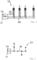
- temperature sensors 1-19 can be assigned to the working rotors 101 of the harvesting machine 100 or to the roller bearings with which the mentioned working rotors 101 are rotatably mounted, in order to record the temperature of the respective bearing of the working rotors 101.
- the named temperature sensors 1-19 can be designed as analog sensors that provide an analog temperature signal, or alternatively also work digitally and provide a digital temperature signal.
- the named temperature sensors 1-19 can be connected to one another by a BUS 20 and/or to an evaluation device 21 be connected in order to be able to communicate with one another and/or with the evaluation device 21 mentioned.
- the BUS connection mentioned can be constructed as a single-wire connection, but also in the form of a multi-wire connection, cf. 2 and 3 . All temperature signals from all temperature sensors 1-19 are made available to the evaluation device 21 for evaluation via the BUS connection 20 mentioned.
- the temperature sensors 1-19 can also communicate with one another in order, for example, to emit a warning signal on a clearly visible temperature sensor if an excessively high temperature level is measured on another temperature sensor.
- the temperature sensors 1-19 or some or all of them can be provided with a display device, for example an LED or a display, depending on the design of the sensor.
- Said evaluation device 21 can be embodied in the form of an electronic computer device which can have a microprocessor, a program memory and/or a data memory in order to process an evaluation program for evaluating the temperature signals and to output a warning and/or control signal if one of the temperature-monitored Machine components are approaching a critical temperature or are exhibiting unusual behavior over the course of the temperature.
- the temperature signal can show an approximately continuous, flat increase, which signals that the temperature of the monitored component is rising accordingly slightly, almost continuously increases.
- the temperature signal shows a conspicuous, steep rate of increase.
- the temperature signal rises sharply in a relatively short time.
- the evaluation device 21 which detects the sharp increase in temperature in the area of time t 1 , can emit a first warning signal.
- the temperature drops again slightly, for example because contamination and the friction caused by it drop again or because a bearing has again received sufficient lubricant.
- the temperature signal again shows a steep and relatively large increase in absolute value, which is determined by evaluation device 21, whereupon evaluation device 21 can output an alarm signal.
- Said evaluation device 21 can also link the temperature signals of the various temperature sensors 1-19 to one another or compare them with one another in the manner explained in more detail at the outset and can emit corresponding warning and/or control signals if there are noticeable variances. Evaluation device 21 can also link the measured temperature signals to other operating parameters of harvesting machine 100 or compare them therewith, in particular with a working speed and/or a load on the temperature-monitored machine component or another machine component whose working speed and/or load affects the temperature development of the monitored component influenced.
- the evaluation device 21 can also take into account the operating hours or the hours worked when the temperature signals are evaluated, as was explained in more detail at the outset. In particular, the evaluation device 21 can also remain Predict the remaining service life using the temperature signals from the sensors monitoring the respective component.
Landscapes
- Life Sciences & Earth Sciences (AREA)
- Environmental Sciences (AREA)
- Testing Of Devices, Machine Parts, Or Other Structures Thereof (AREA)
- Combines (AREA)
- Harvester Elements (AREA)
Applications Claiming Priority (1)
| Application Number | Priority Date | Filing Date | Title |
|---|---|---|---|
| DE102019120217.5A DE102019120217A1 (de) | 2019-07-26 | 2019-07-26 | Landwirtschaftliche Maschine |
Publications (2)
| Publication Number | Publication Date |
|---|---|
| EP3769604A1 EP3769604A1 (de) | 2021-01-27 |
| EP3769604B1 true EP3769604B1 (de) | 2023-06-28 |
Family
ID=70058216
Family Applications (1)
| Application Number | Title | Priority Date | Filing Date |
|---|---|---|---|
| EP20166694.8A Active EP3769604B1 (de) | 2019-07-26 | 2020-03-30 | Landwirtschaftliche maschine |
Country Status (3)
| Country | Link |
|---|---|
| EP (1) | EP3769604B1 (pl) |
| DE (1) | DE102019120217A1 (pl) |
| PL (1) | PL3769604T3 (pl) |
Families Citing this family (1)
| Publication number | Priority date | Publication date | Assignee | Title |
|---|---|---|---|---|
| US20230257968A1 (en) * | 2022-02-17 | 2023-08-17 | Deere & Company | System and method of monitoring functional status of a heat generating component of a work machine |
Family Cites Families (7)
| Publication number | Priority date | Publication date | Assignee | Title |
|---|---|---|---|---|
| DE10238900A1 (de) * | 2001-08-30 | 2003-03-27 | Schuler Pressen Gmbh & Co | Presse mit einer Einrichtung zur Überwachung von mindestens einer Lagertemperatur |
| DE102004006848A1 (de) * | 2004-02-12 | 2005-09-01 | Deere & Company, Moline | Verfahren und Überwachungssystem zur Überwachung des Zustands von Arbeitsmaschinen |
| US20120159916A1 (en) * | 2007-01-15 | 2012-06-28 | Kanzaki Kokyukoki Manufacturing Co., Ltd. | Control sysytem for motor-driven lawnmower vehicle |
| DE102007039702B4 (de) * | 2007-08-22 | 2011-04-28 | Sew-Eurodrive Gmbh & Co. Kg | Verfahren zur Bestimmung einer Betriebsinformation eines Getriebes eines Antriebs und System |
| CN202042032U (zh) * | 2011-03-04 | 2011-11-16 | 万信超 | 收割机火灾报警器 |
| WO2012159659A1 (de) * | 2011-05-23 | 2012-11-29 | Aktiebolaget Skf | Verfahren und system |
| US20130180225A1 (en) * | 2012-01-14 | 2013-07-18 | Mikhail Dexter | Bearing thermometer system for a piece of equipment |
-
2019
- 2019-07-26 DE DE102019120217.5A patent/DE102019120217A1/de active Pending
-
2020
- 2020-03-30 PL PL20166694.8T patent/PL3769604T3/pl unknown
- 2020-03-30 EP EP20166694.8A patent/EP3769604B1/de active Active
Also Published As
| Publication number | Publication date |
|---|---|
| PL3769604T3 (pl) | 2023-12-11 |
| DE102019120217A1 (de) | 2021-01-28 |
| EP3769604A1 (de) | 2021-01-27 |
Similar Documents
| Publication | Publication Date | Title |
|---|---|---|
| EP1997366B1 (de) | Landwirtschaftliche Erntemaschine mit einer Fremdkörpererkennungsvorrichtung | |
| EP1004234B1 (de) | Einrichtung zur Überwachung der Einzugsbaugruppe einer landwirtschaftlichen Erntemaschine | |
| US20130167498A1 (en) | Agricultural implement having knife load responsive infeed cutter | |
| EP2702858B2 (de) | Erntemaschine mit Gutzufuhrregelung | |
| DE19835166C2 (de) | Verfahren und Vorrichtung zum Feststellen der Preßdichte von Ballen | |
| DE19904626C2 (de) | Verfahren zum Erkennen von Fremdkörpern in Erntemaschinen | |
| EP3769604B1 (de) | Landwirtschaftliche maschine | |
| EP3729949B1 (de) | Ladewagen mit ernte-ertragserfassung | |
| EP3146833B1 (de) | Landwirtschaftliche arbeitsmaschine | |
| EP3530101A1 (de) | Selbstfahrender feldhäcksler | |
| EP2742794B1 (de) | Landwirtschaftliche Erntemaschine und Verfahren zum Warten einer solchen Erntemaschine | |
| EP1066745B1 (de) | Verfahren und Einrichtung zur Steuerung der Förder- und Arbeitsorgane landwirtschaftlicher Erntemaschinen | |
| EP2377385B1 (de) | Verfahren zur Feststellung eines sich an einem Arbeitsorgan einer selbstfahrenden Erntemaschine ausbildenden Erntegutstaus sowie Steuereinrichtung | |
| EP2965610B1 (de) | Feldhäcksler mit überlastungsschutz | |
| EP2179642B1 (de) | Landwirtschaftliche Erntemaschine | |
| DE102020000725B4 (de) | Landwirtschaftliche Arbeitsmaschine mit einer Messanordnung, Messanordnung für die landwirtschaftliche Arbeitsmaschine und Verfahren zum Messen einer Kontur eines sich bewegenden Bauteils der landwirtschaftlichen Arbeitsmaschine | |
| EP3381262B1 (de) | Verfahren zum betreiben einer landwirtschaftlichen erntemaschine | |
| DE102014008068B4 (de) | Selbstfahrender Feldhäcksler | |
| EP2885961B1 (de) | Selbstfahrende Erntemaschine | |
| EP2803259B1 (de) | Kombination aus einem Zugfahrzeug und einer landwirtschaftlichen Ballenpresse | |
| DE102013107757B4 (de) | Verfahren zum Betreiben eines landwirtschaftlichen Ladewagens und Steuerungseinrichtung | |
| EP4209124B1 (de) | Feldhäcksler | |
| DE102015008745B4 (de) | Rundballenpresse | |
| EP4410087B1 (de) | Selbstfahrende landwirtschaftliche erntemaschine | |
| EP2108248B1 (de) | Feldhäcksler und Einzugsvorrichtung für einen Feldhäcksler |
Legal Events
| Date | Code | Title | Description |
|---|---|---|---|
| PUAI | Public reference made under article 153(3) epc to a published international application that has entered the european phase |
Free format text: ORIGINAL CODE: 0009012 |
|
| STAA | Information on the status of an ep patent application or granted ep patent |
Free format text: STATUS: THE APPLICATION HAS BEEN PUBLISHED |
|
| AK | Designated contracting states |
Kind code of ref document: A1 Designated state(s): AL AT BE BG CH CY CZ DE DK EE ES FI FR GB GR HR HU IE IS IT LI LT LU LV MC MK MT NL NO PL PT RO RS SE SI SK SM TR |
|
| AX | Request for extension of the european patent |
Extension state: BA ME |
|
| STAA | Information on the status of an ep patent application or granted ep patent |
Free format text: STATUS: REQUEST FOR EXAMINATION WAS MADE |
|
| 17P | Request for examination filed |
Effective date: 20210727 |
|
| RBV | Designated contracting states (corrected) |
Designated state(s): AL AT BE BG CH CY CZ DE DK EE ES FI FR GB GR HR HU IE IS IT LI LT LU LV MC MK MT NL NO PL PT RO RS SE SI SK SM TR |
|
| GRAP | Despatch of communication of intention to grant a patent |
Free format text: ORIGINAL CODE: EPIDOSNIGR1 |
|
| STAA | Information on the status of an ep patent application or granted ep patent |
Free format text: STATUS: GRANT OF PATENT IS INTENDED |
|
| INTG | Intention to grant announced |
Effective date: 20230221 |
|
| GRAS | Grant fee paid |
Free format text: ORIGINAL CODE: EPIDOSNIGR3 |
|
| GRAA | (expected) grant |
Free format text: ORIGINAL CODE: 0009210 |
|
| STAA | Information on the status of an ep patent application or granted ep patent |
Free format text: STATUS: THE PATENT HAS BEEN GRANTED |
|
| AK | Designated contracting states |
Kind code of ref document: B1 Designated state(s): AL AT BE BG CH CY CZ DE DK EE ES FI FR GB GR HR HU IE IS IT LI LT LU LV MC MK MT NL NO PL PT RO RS SE SI SK SM TR |
|
| REG | Reference to a national code |
Ref country code: CH Ref legal event code: EP |
|
| REG | Reference to a national code |
Ref country code: AT Ref legal event code: REF Ref document number: 1581876 Country of ref document: AT Kind code of ref document: T Effective date: 20230715 |
|
| REG | Reference to a national code |
Ref country code: IE Ref legal event code: FG4D Free format text: LANGUAGE OF EP DOCUMENT: GERMAN |
|
| REG | Reference to a national code |
Ref country code: DE Ref legal event code: R096 Ref document number: 502020003916 Country of ref document: DE |
|
| REG | Reference to a national code |
Ref country code: NL Ref legal event code: FP |
|
| REG | Reference to a national code |
Ref country code: LT Ref legal event code: MG9D |
|
| PG25 | Lapsed in a contracting state [announced via postgrant information from national office to epo] |
Ref country code: SE Free format text: LAPSE BECAUSE OF FAILURE TO SUBMIT A TRANSLATION OF THE DESCRIPTION OR TO PAY THE FEE WITHIN THE PRESCRIBED TIME-LIMIT Effective date: 20230628 Ref country code: NO Free format text: LAPSE BECAUSE OF FAILURE TO SUBMIT A TRANSLATION OF THE DESCRIPTION OR TO PAY THE FEE WITHIN THE PRESCRIBED TIME-LIMIT Effective date: 20230928 |
|
| PG25 | Lapsed in a contracting state [announced via postgrant information from national office to epo] |
Ref country code: RS Free format text: LAPSE BECAUSE OF FAILURE TO SUBMIT A TRANSLATION OF THE DESCRIPTION OR TO PAY THE FEE WITHIN THE PRESCRIBED TIME-LIMIT Effective date: 20230628 Ref country code: LV Free format text: LAPSE BECAUSE OF FAILURE TO SUBMIT A TRANSLATION OF THE DESCRIPTION OR TO PAY THE FEE WITHIN THE PRESCRIBED TIME-LIMIT Effective date: 20230628 Ref country code: LT Free format text: LAPSE BECAUSE OF FAILURE TO SUBMIT A TRANSLATION OF THE DESCRIPTION OR TO PAY THE FEE WITHIN THE PRESCRIBED TIME-LIMIT Effective date: 20230628 Ref country code: HR Free format text: LAPSE BECAUSE OF FAILURE TO SUBMIT A TRANSLATION OF THE DESCRIPTION OR TO PAY THE FEE WITHIN THE PRESCRIBED TIME-LIMIT Effective date: 20230628 Ref country code: GR Free format text: LAPSE BECAUSE OF FAILURE TO SUBMIT A TRANSLATION OF THE DESCRIPTION OR TO PAY THE FEE WITHIN THE PRESCRIBED TIME-LIMIT Effective date: 20230929 |
|
| PG25 | Lapsed in a contracting state [announced via postgrant information from national office to epo] |
Ref country code: FI Free format text: LAPSE BECAUSE OF FAILURE TO SUBMIT A TRANSLATION OF THE DESCRIPTION OR TO PAY THE FEE WITHIN THE PRESCRIBED TIME-LIMIT Effective date: 20230628 |
|
| PG25 | Lapsed in a contracting state [announced via postgrant information from national office to epo] |
Ref country code: SK Free format text: LAPSE BECAUSE OF FAILURE TO SUBMIT A TRANSLATION OF THE DESCRIPTION OR TO PAY THE FEE WITHIN THE PRESCRIBED TIME-LIMIT Effective date: 20230628 |
|
| PG25 | Lapsed in a contracting state [announced via postgrant information from national office to epo] |
Ref country code: ES Free format text: LAPSE BECAUSE OF FAILURE TO SUBMIT A TRANSLATION OF THE DESCRIPTION OR TO PAY THE FEE WITHIN THE PRESCRIBED TIME-LIMIT Effective date: 20230628 |
|
| PG25 | Lapsed in a contracting state [announced via postgrant information from national office to epo] |
Ref country code: IS Free format text: LAPSE BECAUSE OF FAILURE TO SUBMIT A TRANSLATION OF THE DESCRIPTION OR TO PAY THE FEE WITHIN THE PRESCRIBED TIME-LIMIT Effective date: 20231028 |
|
| PG25 | Lapsed in a contracting state [announced via postgrant information from national office to epo] |
Ref country code: SM Free format text: LAPSE BECAUSE OF FAILURE TO SUBMIT A TRANSLATION OF THE DESCRIPTION OR TO PAY THE FEE WITHIN THE PRESCRIBED TIME-LIMIT Effective date: 20230628 Ref country code: SK Free format text: LAPSE BECAUSE OF FAILURE TO SUBMIT A TRANSLATION OF THE DESCRIPTION OR TO PAY THE FEE WITHIN THE PRESCRIBED TIME-LIMIT Effective date: 20230628 Ref country code: RO Free format text: LAPSE BECAUSE OF FAILURE TO SUBMIT A TRANSLATION OF THE DESCRIPTION OR TO PAY THE FEE WITHIN THE PRESCRIBED TIME-LIMIT Effective date: 20230628 Ref country code: PT Free format text: LAPSE BECAUSE OF FAILURE TO SUBMIT A TRANSLATION OF THE DESCRIPTION OR TO PAY THE FEE WITHIN THE PRESCRIBED TIME-LIMIT Effective date: 20231030 Ref country code: IS Free format text: LAPSE BECAUSE OF FAILURE TO SUBMIT A TRANSLATION OF THE DESCRIPTION OR TO PAY THE FEE WITHIN THE PRESCRIBED TIME-LIMIT Effective date: 20231028 Ref country code: ES Free format text: LAPSE BECAUSE OF FAILURE TO SUBMIT A TRANSLATION OF THE DESCRIPTION OR TO PAY THE FEE WITHIN THE PRESCRIBED TIME-LIMIT Effective date: 20230628 Ref country code: EE Free format text: LAPSE BECAUSE OF FAILURE TO SUBMIT A TRANSLATION OF THE DESCRIPTION OR TO PAY THE FEE WITHIN THE PRESCRIBED TIME-LIMIT Effective date: 20230628 Ref country code: CZ Free format text: LAPSE BECAUSE OF FAILURE TO SUBMIT A TRANSLATION OF THE DESCRIPTION OR TO PAY THE FEE WITHIN THE PRESCRIBED TIME-LIMIT Effective date: 20230628 |
|
| PG25 | Lapsed in a contracting state [announced via postgrant information from national office to epo] |
Ref country code: PL Free format text: LAPSE BECAUSE OF FAILURE TO SUBMIT A TRANSLATION OF THE DESCRIPTION OR TO PAY THE FEE WITHIN THE PRESCRIBED TIME-LIMIT Effective date: 20230628 |
|
| REG | Reference to a national code |
Ref country code: DE Ref legal event code: R097 Ref document number: 502020003916 Country of ref document: DE |
|
| PG25 | Lapsed in a contracting state [announced via postgrant information from national office to epo] |
Ref country code: DK Free format text: LAPSE BECAUSE OF FAILURE TO SUBMIT A TRANSLATION OF THE DESCRIPTION OR TO PAY THE FEE WITHIN THE PRESCRIBED TIME-LIMIT Effective date: 20230628 |
|
| PLBE | No opposition filed within time limit |
Free format text: ORIGINAL CODE: 0009261 |
|
| STAA | Information on the status of an ep patent application or granted ep patent |
Free format text: STATUS: NO OPPOSITION FILED WITHIN TIME LIMIT |
|
| 26N | No opposition filed |
Effective date: 20240402 |
|
| PG25 | Lapsed in a contracting state [announced via postgrant information from national office to epo] |
Ref country code: SI Free format text: LAPSE BECAUSE OF FAILURE TO SUBMIT A TRANSLATION OF THE DESCRIPTION OR TO PAY THE FEE WITHIN THE PRESCRIBED TIME-LIMIT Effective date: 20230628 |
|
| PG2D | Information on lapse in contracting state deleted |
Ref country code: PL |
|
| REG | Reference to a national code |
Ref country code: CH Ref legal event code: PL |
|
| PG25 | Lapsed in a contracting state [announced via postgrant information from national office to epo] |
Ref country code: BG Free format text: LAPSE BECAUSE OF FAILURE TO SUBMIT A TRANSLATION OF THE DESCRIPTION OR TO PAY THE FEE WITHIN THE PRESCRIBED TIME-LIMIT Effective date: 20230628 |
|
| PG25 | Lapsed in a contracting state [announced via postgrant information from national office to epo] |
Ref country code: LU Free format text: LAPSE BECAUSE OF NON-PAYMENT OF DUE FEES Effective date: 20240330 |
|
| PG25 | Lapsed in a contracting state [announced via postgrant information from national office to epo] |
Ref country code: MC Free format text: LAPSE BECAUSE OF FAILURE TO SUBMIT A TRANSLATION OF THE DESCRIPTION OR TO PAY THE FEE WITHIN THE PRESCRIBED TIME-LIMIT Effective date: 20230628 |
|
| GBPC | Gb: european patent ceased through non-payment of renewal fee |
Effective date: 20240330 |
|
| PG25 | Lapsed in a contracting state [announced via postgrant information from national office to epo] |
Ref country code: MC Free format text: LAPSE BECAUSE OF FAILURE TO SUBMIT A TRANSLATION OF THE DESCRIPTION OR TO PAY THE FEE WITHIN THE PRESCRIBED TIME-LIMIT Effective date: 20230628 Ref country code: LU Free format text: LAPSE BECAUSE OF NON-PAYMENT OF DUE FEES Effective date: 20240330 Ref country code: BG Free format text: LAPSE BECAUSE OF FAILURE TO SUBMIT A TRANSLATION OF THE DESCRIPTION OR TO PAY THE FEE WITHIN THE PRESCRIBED TIME-LIMIT Effective date: 20230628 |
|
| REG | Reference to a national code |
Ref country code: BE Ref legal event code: MM Effective date: 20240331 |
|
| PG25 | Lapsed in a contracting state [announced via postgrant information from national office to epo] |
Ref country code: BE Free format text: LAPSE BECAUSE OF NON-PAYMENT OF DUE FEES Effective date: 20240331 |
|
| PG25 | Lapsed in a contracting state [announced via postgrant information from national office to epo] |
Ref country code: GB Free format text: LAPSE BECAUSE OF NON-PAYMENT OF DUE FEES Effective date: 20240330 |
|
| PG25 | Lapsed in a contracting state [announced via postgrant information from national office to epo] |
Ref country code: GB Free format text: LAPSE BECAUSE OF NON-PAYMENT OF DUE FEES Effective date: 20240330 Ref country code: BE Free format text: LAPSE BECAUSE OF NON-PAYMENT OF DUE FEES Effective date: 20240331 Ref country code: CH Free format text: LAPSE BECAUSE OF NON-PAYMENT OF DUE FEES Effective date: 20240331 |
|
| PGFP | Annual fee paid to national office [announced via postgrant information from national office to epo] |
Ref country code: DE Payment date: 20250320 Year of fee payment: 6 |
|
| PGFP | Annual fee paid to national office [announced via postgrant information from national office to epo] |
Ref country code: NL Payment date: 20250321 Year of fee payment: 6 |
|
| PGFP | Annual fee paid to national office [announced via postgrant information from national office to epo] |
Ref country code: IE Payment date: 20250325 Year of fee payment: 6 |
|
| PGFP | Annual fee paid to national office [announced via postgrant information from national office to epo] |
Ref country code: AT Payment date: 20250417 Year of fee payment: 5 |
|
| PGFP | Annual fee paid to national office [announced via postgrant information from national office to epo] |
Ref country code: FR Payment date: 20250325 Year of fee payment: 6 Ref country code: PL Payment date: 20250214 Year of fee payment: 6 |
|
| PGFP | Annual fee paid to national office [announced via postgrant information from national office to epo] |
Ref country code: IT Payment date: 20250306 Year of fee payment: 6 |
|
| PG25 | Lapsed in a contracting state [announced via postgrant information from national office to epo] |
Ref country code: CY Free format text: LAPSE BECAUSE OF FAILURE TO SUBMIT A TRANSLATION OF THE DESCRIPTION OR TO PAY THE FEE WITHIN THE PRESCRIBED TIME-LIMIT; INVALID AB INITIO Effective date: 20200330 |
|
| PG25 | Lapsed in a contracting state [announced via postgrant information from national office to epo] |
Ref country code: HU Free format text: LAPSE BECAUSE OF FAILURE TO SUBMIT A TRANSLATION OF THE DESCRIPTION OR TO PAY THE FEE WITHIN THE PRESCRIBED TIME-LIMIT; INVALID AB INITIO Effective date: 20200330 |
|
| PG25 | Lapsed in a contracting state [announced via postgrant information from national office to epo] |
Ref country code: TR Free format text: LAPSE BECAUSE OF FAILURE TO SUBMIT A TRANSLATION OF THE DESCRIPTION OR TO PAY THE FEE WITHIN THE PRESCRIBED TIME-LIMIT Effective date: 20230628 |