EP3769591B1 - Anlage zur steuerung von in reihe angeordneten signallampen - Google Patents
Anlage zur steuerung von in reihe angeordneten signallampen Download PDFInfo
- Publication number
- EP3769591B1 EP3769591B1 EP19722945.3A EP19722945A EP3769591B1 EP 3769591 B1 EP3769591 B1 EP 3769591B1 EP 19722945 A EP19722945 A EP 19722945A EP 3769591 B1 EP3769591 B1 EP 3769591B1
- Authority
- EP
- European Patent Office
- Prior art keywords
- control module
- optical
- series
- module
- signalling
- Prior art date
- Legal status (The legal status is an assumption and is not a legal conclusion. Google has not performed a legal analysis and makes no representation as to the accuracy of the status listed.)
- Active
Links
Images




Classifications
-
- B—PERFORMING OPERATIONS; TRANSPORTING
- B64—AIRCRAFT; AVIATION; COSMONAUTICS
- B64F—GROUND OR AIRCRAFT-CARRIER-DECK INSTALLATIONS SPECIALLY ADAPTED FOR USE IN CONNECTION WITH AIRCRAFT; DESIGNING, MANUFACTURING, ASSEMBLING, CLEANING, MAINTAINING OR REPAIRING AIRCRAFT, NOT OTHERWISE PROVIDED FOR; HANDLING, TRANSPORTING, TESTING OR INSPECTING AIRCRAFT COMPONENTS, NOT OTHERWISE PROVIDED FOR
- B64F1/00—Ground or aircraft-carrier-deck installations
- B64F1/18—Visual or acoustic landing aids
- B64F1/20—Arrangement of optical beacons
- B64F1/205—Arrangement of optical beacons arranged underground, e.g. underground runway lighting units
-
- B—PERFORMING OPERATIONS; TRANSPORTING
- B64—AIRCRAFT; AVIATION; COSMONAUTICS
- B64F—GROUND OR AIRCRAFT-CARRIER-DECK INSTALLATIONS SPECIALLY ADAPTED FOR USE IN CONNECTION WITH AIRCRAFT; DESIGNING, MANUFACTURING, ASSEMBLING, CLEANING, MAINTAINING OR REPAIRING AIRCRAFT, NOT OTHERWISE PROVIDED FOR; HANDLING, TRANSPORTING, TESTING OR INSPECTING AIRCRAFT COMPONENTS, NOT OTHERWISE PROVIDED FOR
- B64F1/00—Ground or aircraft-carrier-deck installations
- B64F1/18—Visual or acoustic landing aids
- B64F1/20—Arrangement of optical beacons
-
- H—ELECTRICITY
- H05—ELECTRIC TECHNIQUES NOT OTHERWISE PROVIDED FOR
- H05B—ELECTRIC HEATING; ELECTRIC LIGHT SOURCES NOT OTHERWISE PROVIDED FOR; CIRCUIT ARRANGEMENTS FOR ELECTRIC LIGHT SOURCES, IN GENERAL
- H05B47/00—Circuit arrangements for operating light sources in general, i.e. where the type of light source is not relevant
- H05B47/10—Controlling the light source
- H05B47/155—Coordinated control of two or more light sources
-
- H—ELECTRICITY
- H05—ELECTRIC TECHNIQUES NOT OTHERWISE PROVIDED FOR
- H05B—ELECTRIC HEATING; ELECTRIC LIGHT SOURCES NOT OTHERWISE PROVIDED FOR; CIRCUIT ARRANGEMENTS FOR ELECTRIC LIGHT SOURCES, IN GENERAL
- H05B47/00—Circuit arrangements for operating light sources in general, i.e. where the type of light source is not relevant
- H05B47/10—Controlling the light source
- H05B47/165—Controlling the light source following a pre-assigned programmed sequence; Logic control [LC]
-
- H—ELECTRICITY
- H05—ELECTRIC TECHNIQUES NOT OTHERWISE PROVIDED FOR
- H05B—ELECTRIC HEATING; ELECTRIC LIGHT SOURCES NOT OTHERWISE PROVIDED FOR; CIRCUIT ARRANGEMENTS FOR ELECTRIC LIGHT SOURCES, IN GENERAL
- H05B47/00—Circuit arrangements for operating light sources in general, i.e. where the type of light source is not relevant
- H05B47/20—Responsive to malfunctions or to light source life; for protection
- H05B47/23—Responsive to malfunctions or to light source life; for protection of two or more light sources connected in series
-
- B—PERFORMING OPERATIONS; TRANSPORTING
- B64—AIRCRAFT; AVIATION; COSMONAUTICS
- B64D—EQUIPMENT FOR FITTING IN OR TO AIRCRAFT; FLIGHT SUITS; PARACHUTES; ARRANGEMENT OR MOUNTING OF POWER PLANTS OR PROPULSION TRANSMISSIONS IN AIRCRAFT
- B64D2203/00—Aircraft or airfield lights using LEDs
Definitions
- the present invention relates to an installation for controlling signalling lights arranged in series, in particular airport runway lights.
- the longitudinal rows mark out the travel path for the aircraft, guiding it during take-off/landing, while the transverse rows regulate the advancing movement/stopping of the aircraft which are simultaneously present on the same runway, in order to prevent accidents.
- a first long-standing solution proposed for monitoring these lights involves a carrier-wave transmission module which transmits data and draws on the power supply for its operation, using a primary power supply cable for the runway lights; this module is arranged between each power supply branch-off transformer and the said light.
- DE 101 44 929 A1 which describes an installation for controlling the switching on and switching off of a plurality of signalling lights arranged in series, comprising a unit for managing operation of the installation, with a primary upstream power supply; a primary series circuit for powering the lights, comprising a transformer for each light, the transformers being connected in series to the primary power supply; and a module for controlling each light arranged between a respective transformer and the associated light.
- the control modules and the management unit are connected in parallel by means of an optical-fibre ring bus which provides a data connection independent of the primary power supply series circuit.
- US 6 489 733 B1 describes an airport lighting system wherein a second power supply is integrated into the control module associated with each signalling light, for the purpose of providing power to a controller and a transmitter of the control module.
- US 2006/086893 A1 describes a network of electrical devices, for example electricity meters, which are interconnected in a ring topology using fibre optic connectors, wherein each slave device in the network determines if the address portion of a message from the master device correlates to its own address. If the address correlates, the slave module processes the message while if the address does not correlate, the message is propagated to the next slave module in the network.
- the technical problem which is posed therefore is that of providing an installation for controlling the operating state and/or switching-on/switching off of the signalling lights of airport runways, which provides a solution to or at least reduces the aforementioned technical problems and is in particular designed to allow precise identification and localization of any faults along the line without need for on-site checks.
- a particularly desirable aspect is that the installation should be able to cope with one or more faults which may affect the lights, the devices for controlling the lights or the connections with them or at the least ensure the at least partial operability of the signalling light installation in the event of faults of this type.
- the installation should be able to allow a reduction in the response time needed to identify the fault, so as to ensure an optimum categorization of the airports.
- faults affecting the primary power supply for the lights do not affect either the power supply or communication with the control modules; faults affecting a single control module do not adversely affect the operability of all the other modules and may be identified and located with precision and without delay; faults affecting a single optical connection do not alter the operability of the lights arranged in series, said lights being able to be bypassed by means of the alternative optical channel for connecting the control modules to the management unit.
- faults affecting the optical communication means of a single control module may generally also be resolved without adversely affecting the operability of the lighting system.
- each light 1,...,1m,...1m+1...,1n comprises pairs of lamps L1,L2 connected in series, arranged parallel to the longitudinal direction X-X; however, other configurations are possible where each light comprises a single lamp or a plurality of lamps with longitudinal and/or transverse dimensions and/or combinations thereof; it is envisaged moreover that the lamps may consist for example of light bulbs or LEDs or similar suitable light sources.
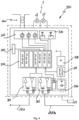
- an example of a lighting assembly for an airport runway comprises: a plurality of lights 1,...,1m,1m+1,...,1n arranged along the runway 2 of an airport and connected in series; the example described refers to a pair of lamps L1, L2 connected together in series for each light 1; and a preferred embodiment of an installation for powering and controlling the lights 1 of a runway which comprises:
- Each successive transformer 200m is in turn connected to the primary winding of the adjacent upstream transformer 200m-1 and to the primary winding of the adjacent downstream transformer 200m+1, thus forming a chain of transformers which constitutes the series power supply circuit of the lights; the primary winding of the last transformer 200n in the series is in turn connected to the primary winding of the adjacent upstream transformer 200n-1 and to the primary power supply 110 so as to close the series circuit.
- each transformer 200m is connected to a respective control module 300m described below;
- each control module 300 comprises:
- the second optical/digital converter 302 of each module 300m is connected to an optical cable 131b which provides a bidirectional connection to the first optical/digital converter of the adjacent downstream control module 300m+1 in the series or, in the case of the module 300n of the last light 1n, to the second optical cable 132a for bidirectional connection to the second optical/digital converter 132 of the management and control unit 100.
- Each second conversion device 302 therefore provides a respective transmitter-receiver pair for transmitting and receiving optical signals to/from the respective adjacent downstream control module 300 or the second converter device 132 of the management and control unit 100.
- the last downstream control module 300n is in turn preferably connected directly to the management and control unit by means of the second optical cable 132a, allowing closing of the first series connection channel again on the control unit 100.
- the first control module 300 of the first upstream light 1 is in turn preferably connected directly to the management and control unit by means of the first optical cable 131a, so as to close the second optical communication channel.
- each control module may further comprise:
- the microprocessor 330 may for example comprise or be associated with:
- control module 300 also comprises:
- the measurement means 310 are of the hall sensor type.
- the module 300 also comprises a sensor 350 for detecting the internal temperature of the module 300; with this detection operation the microprocessor 330 may detect data relating to the operation of the module 320 which increases the temperature when a lamp fuses or switches off; a double check as to operation of the light is therefore obtained by means of the sensor 310 which detects the presence/absence of current passing through a lamp and by means of the sensor 350 which detects the increase in temperature due to the operation of the module 320.
- the data packet may for example comprise a command or signal for switching on/switching off or changing the address Im of a module, and/or a query, for example in the form of a request for checking the state of one or more lamps L1 of a light 1, and/or a request for checking the state of the control module 300.
- one or more data packets may contain information about the state of one or more lamps (fused/operational) and about the energized state of the lamp such as a measurement of the current in the secondary power supply circuit of the lamps connected to the module and/or information about the state of a control module, etc.
- Other examples of information which may be advantageously requested with a query and included in a data packet sent from the module 300 to the management unit 100 include: the address Im of the single module; the detected temperature of the module; the power supply voltage of the module and/or the processor; the firmware version of the control module.
- the communication between the management unit 100 and the control modules 300 arranged upstream of the faulty optical connection 131b may take place on the first bidirectional communication optical channel C1, via the first optical cable 131a, the first control module 300 and the following optical connections between control modules 300; in the case of the control modules 300m, 300n-1, 300n arranged downstream of the faulty optical connection 131b, the communication with the management unit 100 may take place on the second bidirectional communication optical channel C2, via the second optical cable 132a, the last control module 300n situated downstream and the preceding optical connections 131n,131m between adjacent control modules 300n, 300n-1, 300m.
- the communication between the management unit 100 and the control modules 300 arranged upstream of the faulty control module 300m+1 may take place on the first bidirectional communication optical channel C1, via the first optical cable 131a, the first control module 300 and the following optical connections between control modules 300; in the case of the control modules 300n-1, 300n arranged downstream of the faulty control module 300m+1, the communication with the management unit 100 may take place on the second bidirectional communication optical channel C2, via the second optical cable 132a, the last downstream control module 300n and the preceding optical connections 131n,131m between adjacent control modules 300n, 300n-1, 300m.
- the management unit 100 may rapidly detect that the fault relates to a control module 300 and identify with precision which module is not functioning correctly so as to carry out repair thereof. In addition, the operability of the remaining lights, which are controlled by the other control modules 300, will not be penalized in any way.
- Figure 5d illustrates a further example of a malfunction, which in this case relates to the partial breakdown of the second optical/digital converter device 302 (transmitter/receiver) of the control module 300m, which is no longer able to receive data from the next downstream module 300n-1 on the connection 131bm.
- This fault may be for example managed as shown in Fig. 5c for the breakage of a connection 131b or, with the preferred configuration described of the two channels C1,C2, by maintaining the full functionality of the first channel C1 in the transmission direction from upstream M to downstream V, with return to the management unit 110 by means of the last module 300n and the second optical cable 132a.
- the second channel C2 may instead be used in both directions, but only as far as the adjacent module 300n-1 downstream of the module 300m affected by the fault.
- the data packet is updated, following each query, with the values obtained from the modules which are subsequently interrogated, and transmitted to the next module so as to reduce the latency time and speed up the checks of the various modules;
- the data packet also integrates the value of the voltage present at the input of the DC sense optical isolated circuit 336; the operative voltage value of 5 V dc of the module 300m present on the DC-DC converter isolated circuit 337; and the value of the temperature detected by the sensor 350; said values are forwarded to the secondary optical converter 302 which transfers them to the cabin computer 120 via the following downstream modules 300 and the optical cable 132a of the secondary optical channel.
- the module 300 and the associated operation for a simplified configuration with only one lamp for each light 1, thus reducing the number of associated circuits for each light 1 and therefore the corresponding data which is no longer needed, or alternatively a configuration with three or more lamps for each light 1.
- a method for checking signalling lights arranged in series, in particular lights of airport runways by means of an installation according to a preferred embodiment described above is further envisaged; the method, for the sake of easier illustration described with reference to the first communication channel C1, comprises the following steps:
Landscapes
- Engineering & Computer Science (AREA)
- Physics & Mathematics (AREA)
- Acoustics & Sound (AREA)
- Mechanical Engineering (AREA)
- Aviation & Aerospace Engineering (AREA)
- Circuit Arrangement For Electric Light Sources In General (AREA)
Claims (13)
- Anlage zur Stromversorgung und Steuerung einer Vielzahl von in Reihe angeordneten Signalleuchten (1), wobei jede der Signalleuchten (1) mindestens eine Lichtquelle (L1, L2) umfasst, wobei die Anlage umfasst:- eine Verwaltungseinheit (100) für die Fernprogrammierung/-verwaltung des Betriebs der Anlage, einschließlich einer stromaufwärtigen (M) Primärstromversorgung (110);- eine Primärreihenschaltung zur Stromversorgung der Signalleuchten, einschließlich einer Kette von Transformatoren (200), wobei jeder Transformator (200) der Kette von Transformatoren zur Stromversorgung einer jeweiligen Signalleuchte der Vielzahl von Signalleuchten (1) dient und wobei eine Primärwicklung jedes Transformators der Kette von Transformatoren in Reihe mit der Primärstromversorgung (110) verbunden ist;- eine Reihe von Steuermodulen (300, 300m, 300n), wobei jedes Steuermodul (300) zur Steuerung einer jeweiligen der Signalleuchten (1) dient und so konfiguriert ist, dass es elektrisch zwischen einem jeweiligen Transformator (200) der Kette von Transformatoren und der zugehörigen Signalleuchte (1) angeordnet ist;- ein erstes optisches Kabel (131a) zur bidirektionalen Verbindung des ersten stromaufwärtigen Steuermoduls (300) der Reihe von Steuermodulen mit der Verwaltungseinheit (100);- ein zweites optisches Kabel (132a) zur bidirektionalen Verbindung des letzten stromabwärtigen Steuermoduls (300n) der Reihe von Steuermodulen mit der Verwaltungseinheit (100);- wobei jedes Steuermodul (300) der Reihe von Steuermodulen, die zwischen dem ersten stromaufwärtigen Steuermodul und dem letzten stromabwärtigen Steuermodul (300n) angeordnet sind, mit einem angrenzenden stromaufwärtigen Steuermodul und mit einem angrenzenden stromabwärtigen Steuermodul mittels einer jeweiligen bidirektionalen optischen Verbindung (131bm) in Reihe geschaltet ist;dadurch ausgebildet wird: einen ersten bidirektionalen Kommunikationsoptikkanal (C1), der zumindest die Verwaltungseinheit (100), das erste Steuermodul (300) der ersten stromaufwärtigen Signalleuchte (1) und die folgenden Steuermodule (300m) in einer Übertragungsrichtung von stromaufwärts (M) nach stromabwärts (V) und in einer Empfangsrichtung von stromabwärts (V) nach stromaufwärts (M) in Reihe miteinander verbindet; und einen zweiten bidirektionalen Kommunikationsoptikkanal, der die Verwaltungseinheit (100), das Steuermodul (300n) der letzten stromabwärtigen Signalleuchte (1n) und die vorangehenden Steuermodule (300m) in einer Übertragungsrichtung von stromabwärts (V) nach stromaufwärts (M) und in einer Empfangsrichtung von stromaufwärts (M) nach stromabwärts (V) in Reihe verbindet;dadurch gekennzeichnet, dass die Anlage weiter eine Sekundärstromversorgungsschaltung (140) für die Stromversorgung der Steuermodule (300) umfasst, die unabhängig von der Primärreihenschaltung und der Primärstromversorgung (110) für die Stromversorgung der Signalleuchten (1) ist.
- Anlage nach Anspruch 1, dadurch gekennzeichnet, dass jedes Steuermodul (300) durch eine Adresse (1, 1m, 1m+1, 1n) identifiziert wird, die dazu dient, seine Position entlang der Reihe der Steuermodule zu definieren.
- Anlage nach Anspruch 1 oder 2, wobei die Verwaltungseinheit (100) umfasst:- eine erste primäre optische/digitale Umwandlungsvorrichtung (131) und eine zweite primäre optische/digitale Umwandlungsvorrichtung (132), die jeweils dafür ausgelegt sind, ein entsprechendes optisches Eingangssignal aufzunehmen und in ein entsprechendes digitales Signal umzuwandeln und umgekehrt ein entsprechendes digitales Signal in ein entsprechendes optisches Signal umzuwandeln, das an ihrem Ausgang übertragen werden soll;wobei die erste primäre optische/digitale Umwandlungsvorrichtung (131) mit dem ersten optischen Kabel (131a) für die Verbindung mit dem ersten Steuermodul (300) der ersten stromaufwärtigen Signalleuchte (1) verbunden ist, um optische Signale von/zu der Reihe von Steuermodulen (300) der Signalleuchten (1) aufzunehmen/zu übertragen, und die zweite primäre optische/digitale Umwandlungsvorrichtung (132), die mit dem zweiten optischen Kabel (132a) für die Verbindung mit dem letzten Steuermodul (300n) der letzten stromabwärtigen Signalleuchte (1n) verbunden ist, um optische Signale von/zu der Reihe der Steuermodule (300) der Signalleuchten (1) aufzunehmen/zu übertragen.
- Anlage nach einem der Ansprüche 1-3, wobei jedes Steuermodul (300) umfasst:- eine erste sekundäre optische/digitale Umwandlungsvorrichtung (301) und eine zweite sekundäre optische/digitale Umwandlungsvorrichtung (302), die jeweils dazu bestimmt sind, ein optisches Eingangssignal aufzunehmen und in ein digitales Signal umzuwandeln und umgekehrt ein digitales Ausgangssignal in ein zu übertragendes optisches Ausgangssignal umzuwandeln;und wobei die erste sekundäre optische/digitale Umwandlungsvorrichtung (301) mit dem jeweiligen bidirektionalen optischen Kabel verbunden ist, das mit der zweiten sekundären optischen/digitalen Umwandlungsvorrichtung des angrenzenden stromaufwärtigen Moduls (300m-1) in der Reihe der Steuermodule oder, im Falle des ersten stromaufwärtigen Steuermoduls (300) für die erste Signalleuchte (1), mit dem ersten optischen Kabel (131a) für eine bidirektionale Verbindung mit der Verwaltungseinheit (100) verbunden ist; unddie zweite sekundäre optische/digitale Umwandlungsvorrichtung (302) mit dem jeweiligen bidirektionalen optischen Kabel verbunden ist, das mit der ersten sekundären optischen/digitalen Umwandlungsvorrichtung des angrenzenden stromabwärtigen Steuermoduls (300m+1) in der Reihe der Steuermodule oder, im Falle des letzten stromabwärtigen Steuermoduls (300n) für die letzte Signalleuchte (1n), mit dem zweiten optischen Kabel (132a) zur bidirektionalen Verbindung mit der Verwaltungseinheit (100) verbunden ist.
- Anlage nach einem der vorhergehenden Ansprüche, wobei der erste bidirektionale Kommunikationsoptikkanal (C1) auch das letzte stromabwärtige Steuermodul (300n) mittels des zweiten optischen Kabels (132a) zur bidirektionalen Verbindung des letzten stromabwärtigen Steuermoduls (300n) der Reihe mit der Verwaltungseinheit (100) zurückverbindet; und wobei der zweite bidirektionale Kommunikationsoptikkanal (C2) auch das erste Steuermodul (300) der ersten stromaufwärtigen Signalleuchte (1) mit der Verwaltungseinheit (100) zurückverbindet, und zwar mit Hilfe des ersten optischen Kabels (131a) zur bidirektionalen Verbindung des ersten stromaufwärtigen Moduls (330) der Serie mit der Verwaltungseinheit (100).
- Anlage nach einem der Ansprüche 1-5, dadurch gekennzeichnet, dass jedes Steuermodul (300) umfasst:- Messmittel (310) zum Bestimmen des Wertes des Stroms, der durch den jeweiligen Transformator (200) und/oder jede Lichtquelle (L1, L2) der jeweiligen Signalleuchte (1) und/oder jede Unterbrechung einer von ihnen fließt; und- Mittel (320) zum Ein- und Ausschalten der jeweiligen Leuchte (1), die zwischen der Sekundärwicklung (201b) des Transformators (200) und der zugehörigen Signalleuchte (1) angeordnet sind, wobei die Mittel auch in der Lage sind, beschädigte Signalleuchten (1) kurzzuschließen, wobei die Ein- und Ausschalt- und Kurzschlussmittel (320) vorzugsweise Fotokoppler sind; und- einen Mikroprozessor (330), der vorzugsweise zwischen der Messmittel (310) und dem Ein- und Ausschaltmittel (320) angeordnet ist.
- Anlage nach einem der vorhergehenden Ansprüche, dadurch gekennzeichnet, dass jedes Steuermodul (300) umfasst:eine optische Schaltung (336), die galvanisch isoliert ist und dazu dient, den Wert der Spannung zu messen, die dem Eingang des Moduls (300) über die Sekundärstromversorgungsschaltung (140) zugeführt wird; und/odereine isolierte DC-DC-Wandlerschaltung (337) zur Messung des Wertes der Betriebsspannung des Moduls (300); und/odereinen Sensor (350) zum Detektieren einer internen Temperatur des Moduls (300).
- Anlage nach einem der Ansprüche 1-7, dadurch gekennzeichnet, dass die Verwaltungseinheit (100) zur Fernprogrammierung und -verwaltung des Betriebs der Anlage umfasst:- einen Konstantstromregler, der in der stromaufwärtigen (M) Primärstromversorgung (110) enthalten ist, um insbesondere einen/eine Einschaltstrom/-spannung für die Primärreihenschaltung zur Versorgung der Leuchten (1) über einen Stromversorgungszweig (110a) für die Primärwicklungen (201a) der Transformatoren (200) und einen Rückführungszweig (110b) zum Schließen der Primärreihenschaltung zu liefern;- einen Kabinenprozessor (120), der Arbeitsspeicher und eine CPU zur Programmierung und Verwaltung des Betriebs und der Fernsteuerung der Anlage umfasst.
- Beleuchtungsbaugruppe umfassend eine Anlage nach einem der Ansprüche 1-8 und eine Vielzahl von in Reihe angeordneten Signalleuchten (1), wobei die Signalleuchten (1) vorzugsweise parallel zu den Roll- und/oder Startbahnen angeordnete Flughafensignalleuchten und/oder quer zu den Roll- und/oder Startbahnen angeordnete Flughafensignalleuchten sind.
- Anlage nach Anspruch 4, wenn sie von den beiden Ansprüchen 2 und 3 abhängt, wobei, zur Steuerung des Zustands und/oder des Ein-/Ausschaltens einer oder mehrerer der Signalleuchten, die Verwaltungseinheit (100) konfiguriert ist, um:- die Signalleuchten (1) und/oder die Lichtquellen (L1;L2) jeder Signalleuchte (1) zu identifizieren, die mit jedem Steuermodul (300) der Reihe von Steuermodulen verbunden sind;- einen Befehl und/oder eine Anfrage zu erzeugen, die an ein entsprechendes Steuermodul (300m) mit einer ersten Adresse (Im) adressiert ist;
wobei die erste primäre optische/digitale Umwandlungsvorrichtung (131) oder die zweite primäre optische/digitale Umwandlungsvorrichtung (132) der Verwaltungseinheit konfiguriert sind, um- den Befehl und/oder die Anfrage von digital in optisch umzuwandeln, die an das Steuermodul (300m) mit der ersten Adresse (Im) adressiert ist;- den umgewandelten Befehl und/oder die umgewandelte Anfrage im optischen Format zu senden, der/die an das Steuermodul (300m) mit der ersten Adresse (Im) adressiert ist, durch die erste primäre optische/digitale Umwandlungsvorrichtung (131) auf dem ersten optischen Verbindungskanal (C1) oder durch die zweite primäre optische/digitale Umwandlungsvorrichtung (132) auf dem zweiten optischen Verbindungskanal (C2), wobei der umgewandelte Befehl und/oder die umgewandelte Anfrage von dem ersten stromaufwärtigen Steuermodul (300) bzw. dem letzten stromabwärtigen Steuermodul (300n) aufgenommen wird; undwobei die erste sekundäre optische/digitale Umwandlungsvorrichtung (301) oder die zweite sekundäre optische/digitale Umwandlungsvorrichtung (302) jedes Steuermoduls (300m) der Reihe von Steuermodulen konfiguriert ist, um:- den umgewandelten Befehl und/oder die umgewandelte Anfrage zu empfangen, die auf dem jeweiligen ersten (C1) oder zweiten (C2) optischen Verbindungskanal aufgenommen wurden;- den empfangenen Befehl und/oder die Anfrage von optisch in digital umzuwandeln;wobei jedes Steuermodul (300m) der Reihe von Steuermodulen konfiguriert ist, um:- die Korrespondenz zwischen der ersten Adresse (Im) des eingehenden Befehls und/oder der eingehenden Anfrage und der Adresse des darin gespeicherten Steuermoduls (300m) zu überprüfen; und:wenn JA zur Korrespondenz, Senden einer Bestätigung der Existenz und der Korrespondenz des Steuermoduls mit der ersten Adresse (Im) an die Verwaltungseinheit (100); oderwenn NEIN zur Korrespondenz, Weiterleiten des Befehls und/oder der Anfrage, der und/oder die an das Steuermodul (300m) mit der ersten Adresse (Im) adressiert ist, an das nächste stromabwärtige Steuermodul oder das vorhergehende stromaufwärtige Steuermodul über den ersten optischen Verbindungskanal (C1) bzw. den zweiten optischen Verbindungskanal (C2), bis ein Steuermodul (300m) erreicht ist, dessen Adresse der ersten Adresse (Im) des Befehls und/oder der Anfrage entspricht. - Anlage nach Ansprüche 6 und 10, wobei jedes Steuermodul der Reihe von Steuermodulen so konfiguriert ist, dass es prüft, ob ein von der Verwaltungseinheit (100) gesendetes Lichtausschalt-/einschaltsignal empfangen wurde, wenn das Steuermodul (300m) von einem Befehl und/oder einer Anfrage mit einer Befehls-/Anfragesadresse erreicht wird, die der Adresse des Steuermoduls (300m) entspricht; und:+ WENN JA, ist das Schaltmittel des Steuermoduls so konfiguriert, dass es die Signalleuchte (1m) aus- und einschaltet;+ WENN NEIN, ist das Messmittel (310) des Steuermoduls (300m) so konfiguriert, dass es den Stromfluss am jeweiligen Transformator (200m) überprüft und feststellt, ob der Stromfluss einem korrekten voreingestellten Wert entspricht;wobei WENN JA zum korrekten Stromfluss am Transformator: das Messmittel (310) des Steuermoduls konfiguriert ist, um einen Stromfluss und einen korrekten Stromwert an der einen oder den mehreren Lichtquellen (L1; L2) der jeweiligen Signalleuchten (1m) zu verifizieren, und wenn es einen Stromfluss gibt und der Stromwert korrekt ist, das Steuermodul konfiguriert ist, um die detektierten Stromwerte in ein Datenpaket zu integrieren und das Datenpaket an das nächste angrenzende stromabwärtige Steuermodul (300m+1) oder das vorhergehende angrenzende stromaufwärtige Steuermodul (300m-1) entlang des ersten optischen Kanals (C1) oder des zweiten optischen Kanals (C2) weiterzuleiten.
- Anlage nach Anspruch 11, wobei:
WENN NEIN zur Verifizierung der korrekten Stromwerte auf dem jeweiligen Transformator (200m), ist jedes Steuermodul der Reihe von Steuermodulen so konfiguriert, dass es einen auf dem jeweiligen Steuermodul (300) vorhandenen Stromspannungswert detektiert, diesen zusammen mit dem Stromspannungswert in ein Datenpaket integriert und das Datenpaket entlang des ersten optischen Kanals (C1) oder des zweiten optischen Kanals (C2) an das nächste angrenzende stromabwärtige Steuermodul (300m+1) oder das vorhergehende angrenzende stromaufwärtige Steuermodul (300m-1) weiterleitet. - Anlage nach Anspruch 11 oder 12, wobei:WENN JA zur Verifizierung des korrekten Stromwertes am jeweiligen Transformator (200m), aberNEIN zur Verifizierung des korrekten Stromwertes an einer oder mehreren Lichtquellen (L1, L2) der Signalleuchte (1m),das jeweilige Steuermodul (300m) so konfiguriert ist, dass es die eine oder mehrere nicht betriebsbereite Lichtquellen (L1, L2) kurzschließt, das Datenpaket mit den Werten der detektierten vorhandenen Ströme aktualisiert und das Datenpaket an das nächste angrenzende stromabwärtige Steuermodul (300m+1) oder das vorhergehende angrenzende stromaufwärtige Steuermodul (300m-1 ) entlang des ersten optischen Kanals (C1) oder des zweiten optischen Kanals (C2) überträgt.
Applications Claiming Priority (2)
| Application Number | Priority Date | Filing Date | Title |
|---|---|---|---|
| IT201800003738 | 2018-03-19 | ||
| PCT/IB2019/052163 WO2019180574A1 (en) | 2018-03-19 | 2019-03-18 | Installation and method for controlling signalling lights arranged in series |
Publications (2)
| Publication Number | Publication Date |
|---|---|
| EP3769591A1 EP3769591A1 (de) | 2021-01-27 |
| EP3769591B1 true EP3769591B1 (de) | 2024-11-06 |
Family
ID=62751256
Family Applications (1)
| Application Number | Title | Priority Date | Filing Date |
|---|---|---|---|
| EP19722945.3A Active EP3769591B1 (de) | 2018-03-19 | 2019-03-18 | Anlage zur steuerung von in reihe angeordneten signallampen |
Country Status (3)
| Country | Link |
|---|---|
| US (1) | US11459119B2 (de) |
| EP (1) | EP3769591B1 (de) |
| WO (1) | WO2019180574A1 (de) |
Families Citing this family (2)
| Publication number | Priority date | Publication date | Assignee | Title |
|---|---|---|---|---|
| US11459120B2 (en) * | 2018-10-26 | 2022-10-04 | HotaluX, Ltd. | Control device, control device system, runway flash lighting device control system, program, and recording medium |
| US11622432B1 (en) * | 2022-02-03 | 2023-04-04 | Seasons 4, Inc. | Serial-configured lighting display with upstream data flow |
Family Cites Families (5)
| Publication number | Priority date | Publication date | Assignee | Title |
|---|---|---|---|---|
| US5926115A (en) * | 1996-06-21 | 1999-07-20 | Adb Alnaco, Inc. | Airfield series circuit communications lighting system and method |
| ATE257967T1 (de) * | 1998-04-21 | 2004-01-15 | Siemens Ag | Beleuchtungsanlage, z.b. flughafen- oder strassenbefeuerungsanlage |
| DE10144929A1 (de) * | 2001-09-12 | 2003-04-30 | Siemens Ag | Einzellampensteuerung für Befeuerungsanlagen auf Flugplätzen ud.dgl. |
| GB2406977A (en) * | 2003-10-04 | 2005-04-13 | Alstom | Airfield lighting system |
| US7388189B2 (en) * | 2004-10-27 | 2008-06-17 | Electro Industries/Gauge Tech | System and method for connecting electrical devices using fiber optic serial communication |
-
2019
- 2019-03-18 EP EP19722945.3A patent/EP3769591B1/de active Active
- 2019-03-18 US US16/980,066 patent/US11459119B2/en active Active
- 2019-03-18 WO PCT/IB2019/052163 patent/WO2019180574A1/en not_active Ceased
Also Published As
| Publication number | Publication date |
|---|---|
| US20210024225A1 (en) | 2021-01-28 |
| WO2019180574A1 (en) | 2019-09-26 |
| EP3769591A1 (de) | 2021-01-27 |
| US11459119B2 (en) | 2022-10-04 |
Similar Documents
| Publication | Publication Date | Title |
|---|---|---|
| US8774622B2 (en) | Airfield lighting control and monitoring system utilizing fiber optic double loop self healing communications | |
| US6556898B2 (en) | Distributed track network control system | |
| KR101907565B1 (ko) | 터널용 전원이중화 자동전환 장비 | |
| US20150091438A1 (en) | Emergency lighting system for an aircraft and aircraft comprising such emergency lighting system | |
| US5644304A (en) | Automatic control system of lights in a series circuit illumination plant, in particular lights for airport signalling | |
| KR101631349B1 (ko) | 항공등화시스템 | |
| US11459119B2 (en) | Installation and method for controlling signalling lights arranged in series | |
| US20070228223A1 (en) | Device for activation and monitoring of a light-signal system for railway traffic | |
| CN210247120U (zh) | 一种基于无线物联网通信的助航灯光监控系统 | |
| US10612759B2 (en) | Monitor, light control system, and light fixture control method | |
| CN111867202A (zh) | 防止跑道侵入的禁止进入排灯控制方法以及系统 | |
| CN108684117A (zh) | 一种基于物联网通信技术的机场助航单灯监控系统 | |
| CN110247700A (zh) | 一种具有光缆保护功能的智能光缆监测系统及方法 | |
| CN113793513A (zh) | 信号机和交通控制系统 | |
| JP4272755B2 (ja) | 信号機および親装置 | |
| US7366369B2 (en) | Transmission of measured values in high-voltage supply units for electrofilters | |
| CN113655752A (zh) | 二总线设备及其自检方法、楼宇自控系统 | |
| CN114415059A (zh) | 信号色灯检测电路和信号色灯状态的检测方法 | |
| JP4783258B2 (ja) | 列車制御ネットワークシステム | |
| EP3772237B1 (de) | Anordnung zur steuerung der beleuchtung in einem fahrzeug | |
| EP3471515B1 (de) | Beleuchtungssystem | |
| CN117595899A (zh) | 中继盒、中继控制方法及火灾探测系统 | |
| HK40039842A (en) | Arrangement for controlling lighting in a vehicle | |
| HK40039842B (en) | Arrangement for controlling lighting in a vehicle | |
| KR20140025765A (ko) | 항공등화시스템 |
Legal Events
| Date | Code | Title | Description |
|---|---|---|---|
| STAA | Information on the status of an ep patent application or granted ep patent |
Free format text: STATUS: UNKNOWN |
|
| STAA | Information on the status of an ep patent application or granted ep patent |
Free format text: STATUS: THE INTERNATIONAL PUBLICATION HAS BEEN MADE |
|
| PUAI | Public reference made under article 153(3) epc to a published international application that has entered the european phase |
Free format text: ORIGINAL CODE: 0009012 |
|
| STAA | Information on the status of an ep patent application or granted ep patent |
Free format text: STATUS: REQUEST FOR EXAMINATION WAS MADE |
|
| 17P | Request for examination filed |
Effective date: 20201009 |
|
| AK | Designated contracting states |
Kind code of ref document: A1 Designated state(s): AL AT BE BG CH CY CZ DE DK EE ES FI FR GB GR HR HU IE IS IT LI LT LU LV MC MK MT NL NO PL PT RO RS SE SI SK SM TR |
|
| AX | Request for extension of the european patent |
Extension state: BA ME |
|
| RAP3 | Party data changed (applicant data changed or rights of an application transferred) |
Owner name: CAZZANI, UMBERTO |
|
| RIN1 | Information on inventor provided before grant (corrected) |
Inventor name: CAZZANI, UMBERTO |
|
| DAV | Request for validation of the european patent (deleted) | ||
| DAX | Request for extension of the european patent (deleted) | ||
| STAA | Information on the status of an ep patent application or granted ep patent |
Free format text: STATUS: EXAMINATION IS IN PROGRESS |
|
| 17Q | First examination report despatched |
Effective date: 20220524 |
|
| REG | Reference to a national code |
Ref country code: DE Ref legal event code: R079 Free format text: PREVIOUS MAIN CLASS: H05B0037030000 Ipc: H05B0047230000 Ref document number: 602019061478 Country of ref document: DE |
|
| RIC1 | Information provided on ipc code assigned before grant |
Ipc: B64F 1/20 20060101ALI20240423BHEP Ipc: H05B 47/23 20200101AFI20240423BHEP |
|
| GRAP | Despatch of communication of intention to grant a patent |
Free format text: ORIGINAL CODE: EPIDOSNIGR1 |
|
| GRAP | Despatch of communication of intention to grant a patent |
Free format text: ORIGINAL CODE: EPIDOSNIGR1 |
|
| STAA | Information on the status of an ep patent application or granted ep patent |
Free format text: STATUS: GRANT OF PATENT IS INTENDED |
|
| INTG | Intention to grant announced |
Effective date: 20240614 |
|
| GRAS | Grant fee paid |
Free format text: ORIGINAL CODE: EPIDOSNIGR3 |
|
| GRAA | (expected) grant |
Free format text: ORIGINAL CODE: 0009210 |
|
| STAA | Information on the status of an ep patent application or granted ep patent |
Free format text: STATUS: THE PATENT HAS BEEN GRANTED |
|
| P01 | Opt-out of the competence of the unified patent court (upc) registered |
Free format text: CASE NUMBER: APP_51769/2024 Effective date: 20240913 |
|
| P02 | Opt-out of the competence of the unified patent court (upc) changed |
Free format text: CASE NUMBER: APP_51782/2024 Effective date: 20240913 |
|
| AK | Designated contracting states |
Kind code of ref document: B1 Designated state(s): AL AT BE BG CH CY CZ DE DK EE ES FI FR GB GR HR HU IE IS IT LI LT LU LV MC MK MT NL NO PL PT RO RS SE SI SK SM TR |
|
| REG | Reference to a national code |
Ref country code: GB Ref legal event code: FG4D |
|
| REG | Reference to a national code |
Ref country code: CH Ref legal event code: EP |
|
| REG | Reference to a national code |
Ref country code: DE Ref legal event code: R096 Ref document number: 602019061478 Country of ref document: DE |
|
| REG | Reference to a national code |
Ref country code: IE Ref legal event code: FG4D |
|
| REG | Reference to a national code |
Ref country code: LT Ref legal event code: MG9D |
|
| REG | Reference to a national code |
Ref country code: NL Ref legal event code: MP Effective date: 20241106 |
|
| PG25 | Lapsed in a contracting state [announced via postgrant information from national office to epo] |
Ref country code: HR Free format text: LAPSE BECAUSE OF FAILURE TO SUBMIT A TRANSLATION OF THE DESCRIPTION OR TO PAY THE FEE WITHIN THE PRESCRIBED TIME-LIMIT Effective date: 20241106 Ref country code: IS Free format text: LAPSE BECAUSE OF FAILURE TO SUBMIT A TRANSLATION OF THE DESCRIPTION OR TO PAY THE FEE WITHIN THE PRESCRIBED TIME-LIMIT Effective date: 20250306 Ref country code: PT Free format text: LAPSE BECAUSE OF FAILURE TO SUBMIT A TRANSLATION OF THE DESCRIPTION OR TO PAY THE FEE WITHIN THE PRESCRIBED TIME-LIMIT Effective date: 20250306 |
|
| PG25 | Lapsed in a contracting state [announced via postgrant information from national office to epo] |
Ref country code: FI Free format text: LAPSE BECAUSE OF FAILURE TO SUBMIT A TRANSLATION OF THE DESCRIPTION OR TO PAY THE FEE WITHIN THE PRESCRIBED TIME-LIMIT Effective date: 20241106 Ref country code: NL Free format text: LAPSE BECAUSE OF FAILURE TO SUBMIT A TRANSLATION OF THE DESCRIPTION OR TO PAY THE FEE WITHIN THE PRESCRIBED TIME-LIMIT Effective date: 20241106 |
|
| REG | Reference to a national code |
Ref country code: AT Ref legal event code: MK05 Ref document number: 1740826 Country of ref document: AT Kind code of ref document: T Effective date: 20241106 |
|
| PG25 | Lapsed in a contracting state [announced via postgrant information from national office to epo] |
Ref country code: BG Free format text: LAPSE BECAUSE OF FAILURE TO SUBMIT A TRANSLATION OF THE DESCRIPTION OR TO PAY THE FEE WITHIN THE PRESCRIBED TIME-LIMIT Effective date: 20241106 |
|
| PG25 | Lapsed in a contracting state [announced via postgrant information from national office to epo] |
Ref country code: ES Free format text: LAPSE BECAUSE OF FAILURE TO SUBMIT A TRANSLATION OF THE DESCRIPTION OR TO PAY THE FEE WITHIN THE PRESCRIBED TIME-LIMIT Effective date: 20241106 |
|
| PG25 | Lapsed in a contracting state [announced via postgrant information from national office to epo] |
Ref country code: NO Free format text: LAPSE BECAUSE OF FAILURE TO SUBMIT A TRANSLATION OF THE DESCRIPTION OR TO PAY THE FEE WITHIN THE PRESCRIBED TIME-LIMIT Effective date: 20250206 |
|
| PG25 | Lapsed in a contracting state [announced via postgrant information from national office to epo] |
Ref country code: LV Free format text: LAPSE BECAUSE OF FAILURE TO SUBMIT A TRANSLATION OF THE DESCRIPTION OR TO PAY THE FEE WITHIN THE PRESCRIBED TIME-LIMIT Effective date: 20241106 Ref country code: GR Free format text: LAPSE BECAUSE OF FAILURE TO SUBMIT A TRANSLATION OF THE DESCRIPTION OR TO PAY THE FEE WITHIN THE PRESCRIBED TIME-LIMIT Effective date: 20250207 Ref country code: AT Free format text: LAPSE BECAUSE OF FAILURE TO SUBMIT A TRANSLATION OF THE DESCRIPTION OR TO PAY THE FEE WITHIN THE PRESCRIBED TIME-LIMIT Effective date: 20241106 |
|
| PGFP | Annual fee paid to national office [announced via postgrant information from national office to epo] |
Ref country code: BE Payment date: 20250326 Year of fee payment: 7 |
|
| PG25 | Lapsed in a contracting state [announced via postgrant information from national office to epo] |
Ref country code: PL Free format text: LAPSE BECAUSE OF FAILURE TO SUBMIT A TRANSLATION OF THE DESCRIPTION OR TO PAY THE FEE WITHIN THE PRESCRIBED TIME-LIMIT Effective date: 20241106 |
|
| PG25 | Lapsed in a contracting state [announced via postgrant information from national office to epo] |
Ref country code: RS Free format text: LAPSE BECAUSE OF FAILURE TO SUBMIT A TRANSLATION OF THE DESCRIPTION OR TO PAY THE FEE WITHIN THE PRESCRIBED TIME-LIMIT Effective date: 20250206 |
|
| PG25 | Lapsed in a contracting state [announced via postgrant information from national office to epo] |
Ref country code: SM Free format text: LAPSE BECAUSE OF FAILURE TO SUBMIT A TRANSLATION OF THE DESCRIPTION OR TO PAY THE FEE WITHIN THE PRESCRIBED TIME-LIMIT Effective date: 20241106 |
|
| PG25 | Lapsed in a contracting state [announced via postgrant information from national office to epo] |
Ref country code: DK Free format text: LAPSE BECAUSE OF FAILURE TO SUBMIT A TRANSLATION OF THE DESCRIPTION OR TO PAY THE FEE WITHIN THE PRESCRIBED TIME-LIMIT Effective date: 20241106 |
|
| PG25 | Lapsed in a contracting state [announced via postgrant information from national office to epo] |
Ref country code: EE Free format text: LAPSE BECAUSE OF FAILURE TO SUBMIT A TRANSLATION OF THE DESCRIPTION OR TO PAY THE FEE WITHIN THE PRESCRIBED TIME-LIMIT Effective date: 20241106 |
|
| PG25 | Lapsed in a contracting state [announced via postgrant information from national office to epo] |
Ref country code: RO Free format text: LAPSE BECAUSE OF FAILURE TO SUBMIT A TRANSLATION OF THE DESCRIPTION OR TO PAY THE FEE WITHIN THE PRESCRIBED TIME-LIMIT Effective date: 20241106 |
|
| PG25 | Lapsed in a contracting state [announced via postgrant information from national office to epo] |
Ref country code: SK Free format text: LAPSE BECAUSE OF FAILURE TO SUBMIT A TRANSLATION OF THE DESCRIPTION OR TO PAY THE FEE WITHIN THE PRESCRIBED TIME-LIMIT Effective date: 20241106 |
|
| PG25 | Lapsed in a contracting state [announced via postgrant information from national office to epo] |
Ref country code: CZ Free format text: LAPSE BECAUSE OF FAILURE TO SUBMIT A TRANSLATION OF THE DESCRIPTION OR TO PAY THE FEE WITHIN THE PRESCRIBED TIME-LIMIT Effective date: 20241106 |
|
| REG | Reference to a national code |
Ref country code: DE Ref legal event code: R097 Ref document number: 602019061478 Country of ref document: DE |
|
| PG25 | Lapsed in a contracting state [announced via postgrant information from national office to epo] |
Ref country code: SE Free format text: LAPSE BECAUSE OF FAILURE TO SUBMIT A TRANSLATION OF THE DESCRIPTION OR TO PAY THE FEE WITHIN THE PRESCRIBED TIME-LIMIT Effective date: 20241106 |
|
| PLBE | No opposition filed within time limit |
Free format text: ORIGINAL CODE: 0009261 |
|
| STAA | Information on the status of an ep patent application or granted ep patent |
Free format text: STATUS: NO OPPOSITION FILED WITHIN TIME LIMIT |
|
| REG | Reference to a national code |
Ref country code: DE Ref legal event code: R119 Ref document number: 602019061478 Country of ref document: DE |
|
| PG25 | Lapsed in a contracting state [announced via postgrant information from national office to epo] |
Ref country code: MC Free format text: LAPSE BECAUSE OF FAILURE TO SUBMIT A TRANSLATION OF THE DESCRIPTION OR TO PAY THE FEE WITHIN THE PRESCRIBED TIME-LIMIT Effective date: 20241106 |
|
| 26N | No opposition filed |
Effective date: 20250807 |
|
| REG | Reference to a national code |
Ref country code: CH Ref legal event code: H13 Free format text: ST27 STATUS EVENT CODE: U-0-0-H10-H13 (AS PROVIDED BY THE NATIONAL OFFICE) Effective date: 20251023 |
|
| GBPC | Gb: european patent ceased through non-payment of renewal fee |
Effective date: 20250318 |
|
| PG25 | Lapsed in a contracting state [announced via postgrant information from national office to epo] |
Ref country code: DE Free format text: LAPSE BECAUSE OF NON-PAYMENT OF DUE FEES Effective date: 20251001 |
|
| PG25 | Lapsed in a contracting state [announced via postgrant information from national office to epo] |
Ref country code: GB Free format text: LAPSE BECAUSE OF NON-PAYMENT OF DUE FEES Effective date: 20250318 |
|
| PG25 | Lapsed in a contracting state [announced via postgrant information from national office to epo] |
Ref country code: CH Free format text: LAPSE BECAUSE OF NON-PAYMENT OF DUE FEES Effective date: 20250331 |
|
| PG25 | Lapsed in a contracting state [announced via postgrant information from national office to epo] |
Ref country code: IE Free format text: LAPSE BECAUSE OF NON-PAYMENT OF DUE FEES Effective date: 20250318 |
|
| PGFP | Annual fee paid to national office [announced via postgrant information from national office to epo] |
Ref country code: LU Payment date: 20260316 Year of fee payment: 8 Ref country code: IT Payment date: 20260318 Year of fee payment: 8 |
|
| PGFP | Annual fee paid to national office [announced via postgrant information from national office to epo] |
Ref country code: FR Payment date: 20260330 Year of fee payment: 8 |