EP3769589B1 - Kommunikationsmodul für ein leuchtmittel-betriebsgerät - Google Patents
Kommunikationsmodul für ein leuchtmittel-betriebsgerät Download PDFInfo
- Publication number
- EP3769589B1 EP3769589B1 EP19721222.8A EP19721222A EP3769589B1 EP 3769589 B1 EP3769589 B1 EP 3769589B1 EP 19721222 A EP19721222 A EP 19721222A EP 3769589 B1 EP3769589 B1 EP 3769589B1
- Authority
- EP
- European Patent Office
- Prior art keywords
- interface
- communication module
- accordance
- protocol
- lamp operating
- Prior art date
- Legal status (The legal status is an assumption and is not a legal conclusion. Google has not performed a legal analysis and makes no representation as to the accuracy of the status listed.)
- Active
Links
Images



Classifications
-
- H—ELECTRICITY
- H05—ELECTRIC TECHNIQUES NOT OTHERWISE PROVIDED FOR
- H05B—ELECTRIC HEATING; ELECTRIC LIGHT SOURCES NOT OTHERWISE PROVIDED FOR; CIRCUIT ARRANGEMENTS FOR ELECTRIC LIGHT SOURCES, IN GENERAL
- H05B47/00—Circuit arrangements for operating light sources in general, i.e. where the type of light source is not relevant
- H05B47/10—Controlling the light source
- H05B47/175—Controlling the light source by remote control
- H05B47/19—Controlling the light source by remote control via wireless transmission
-
- H—ELECTRICITY
- H04—ELECTRIC COMMUNICATION TECHNIQUE
- H04L—TRANSMISSION OF DIGITAL INFORMATION, e.g. TELEGRAPHIC COMMUNICATION
- H04L69/00—Network arrangements, protocols or services independent of the application payload and not provided for in the other groups of this subclass
- H04L69/18—Multiprotocol handlers, e.g. single devices capable of handling multiple protocols
-
- H—ELECTRICITY
- H05—ELECTRIC TECHNIQUES NOT OTHERWISE PROVIDED FOR
- H05B—ELECTRIC HEATING; ELECTRIC LIGHT SOURCES NOT OTHERWISE PROVIDED FOR; CIRCUIT ARRANGEMENTS FOR ELECTRIC LIGHT SOURCES, IN GENERAL
- H05B47/00—Circuit arrangements for operating light sources in general, i.e. where the type of light source is not relevant
- H05B47/10—Controlling the light source
- H05B47/105—Controlling the light source in response to determined parameters
-
- H—ELECTRICITY
- H05—ELECTRIC TECHNIQUES NOT OTHERWISE PROVIDED FOR
- H05B—ELECTRIC HEATING; ELECTRIC LIGHT SOURCES NOT OTHERWISE PROVIDED FOR; CIRCUIT ARRANGEMENTS FOR ELECTRIC LIGHT SOURCES, IN GENERAL
- H05B47/00—Circuit arrangements for operating light sources in general, i.e. where the type of light source is not relevant
- H05B47/10—Controlling the light source
- H05B47/175—Controlling the light source by remote control
- H05B47/18—Controlling the light source by remote control via data-bus transmission
-
- H—ELECTRICITY
- H04—ELECTRIC COMMUNICATION TECHNIQUE
- H04L—TRANSMISSION OF DIGITAL INFORMATION, e.g. TELEGRAPHIC COMMUNICATION
- H04L12/00—Data switching networks
- H04L12/66—Arrangements for connecting between networks having differing types of switching systems, e.g. gateways
-
- H—ELECTRICITY
- H04—ELECTRIC COMMUNICATION TECHNIQUE
- H04L—TRANSMISSION OF DIGITAL INFORMATION, e.g. TELEGRAPHIC COMMUNICATION
- H04L67/00—Network arrangements or protocols for supporting network services or applications
- H04L67/01—Protocols
- H04L67/12—Protocols specially adapted for proprietary or special-purpose networking environments, e.g. medical networks, sensor networks, networks in vehicles or remote metering networks
Definitions
- the present invention relates to a communication module for a lamp operating device and a lamp operating device having at least one such communication module according to the invention.
- the communication module according to the invention enables data to be exchanged at a first or second interface using a first protocol, and at a third interface using a protocol that differs from the first protocol. At the second and third interface, data is preferably exchanged using an Internet of Things (IoT) protocol.
- IoT Internet of Things
- the communication module according to the invention is designed in such a way that a modular series connection of several such communication modules is made possible.
- Lamp operating devices in particular light-emitting diode (LED) operating devices or LED converters, are known from the prior art, which allow control information (in the form of serial information) to be received at an input-side interface, and at least one at an output-side interface (LED) lamps according to the control information with electrical energy and control.
- LED light-emitting diode
- the well-known lamp operating devices receive the control information on the input side using the ESI protocol from the company Enlighted or the very similar standard for networked lighting technology "IoT-Ready" from the IoT-Ready Alliance.
- Lamp operating devices are also known which support one of the protocols Digital Addressable Lighting Interface (DALI), Digital Serial Interface (DSI) or Bluetooth Low Energy (BLE) on the input side.
- DALI Digital Addressable Lighting Interface
- DSI Digital Serial Interface
- BLE Bluetooth Low Energy
- All known lamp operating devices have in common that they each have only one input-side interface for receiving the control information and the incoming interface is limited to one of the above protocols.
- the known lamp operating devices also lack the possibility of independently collecting control information and controlling the output-side interface according to this information.
- U.S. 2015/008846 A1 discloses a known communication module in a lighting system.
- WO 2015/104279 A1 and U.S. 2016/286628 A1 each disclose known communication modules for a lamp operating device.
- a communication module for a lamp operating device which has a first wired interface, a second wired interface, preferably a third interface, and a control unit.
- the first wired interface is designed to be mechanically and functionally connectable to the lamp operating device or another communication module
- the second wired interface is designed to be mechanically and functionally connectable to a network element or another communication module.
- the control unit is connected to the first interface, the second interface and optionally the third interface and is configured to receive serial information according to a first protocol via the first or second interface, to process it, and as processed serial information via at least one of the three interfaces to send.
- the communication module can be connected in series with a further communication module via the first and/or the second interface.
- the control unit is preferably also set up to send and/or receive information via the third interface according to a second protocol that differs from the first protocol.
- control information for controlling the lamp operating device is made available to a lamp operating device by the communication module via its first, wired interface in accordance with a first protocol.
- This control information is generated by the control unit of the communication module from information received at the second interface of the communication module according to the first protocol and/or optionally at the third interface of the communication module according to the second protocol that differs from the first protocol.
- several of the communication modules according to the invention can be combined, that is to say connected in series, or chained (eg in a so-called daisy chain) or stacked.
- the modular design also allows a versatile, configurable and cost-effective solution.
- a lamp operating device is preferably to be understood as meaning an LED operating device, furthermore preferably an LED converter.
- an interface is preferably a mechanical and/or electronic and/or logical connection point between functional units of a data processing or data transmission system, at which the exchange of data, information or control signals takes place.
- the interface is therefore suitable both for mechanical connection or fastening and for wireless or wired electronic connection for the exchange of information (i.e. for functional or logical connection).
- Wired preferably means that information is exchanged using at least one electronic conductor. This includes, for example, a metallic conductor, but also an optical fiber conductor, e.g. a glass fiber.
- a network element is preferably a device in a telecommunications or data transmission network, e.g. a network line (including plug or socket), a hub, switch, router, gateway or server.
- a network element is to be understood as meaning any means that is suitable for generating and/or transmitting information to the communication module.
- the control unit preferably has a microcontroller or a programmable processor.
- the processing of serial information by the control unit is preferably to be understood as converting the serial information so that it is sent to a sending interface via a different protocol than the protocol via which the serial information is received at a receiving interface.
- the processing of serial information by the control unit is also preferably to be understood as forwarding the serial information so that it is sent to a sending interface using the same protocol as the protocol via which the serial information is received at a receiving interface.
- Serial information is preferably understood to be digital information transmitted sequentially over at least one medium (e.g. over a conductor, a fiber, or by means of radio technology), e.g. information transmitted bit by bit.
- the control unit is preferably also set up to transmit serial information via the first interface and/or the second interface using an IoT protocol, or an IoT-Ready protocol, or using one of the protocols ESI, and/or DALI, and/or DSI, and/or Thread, and/or Universal Serial Bus, USB, to send and/or receive.
- IoT is a collective term for technologies that enable individual electronic devices to be networked and interacted through information and communication technologies.
- Any communication protocol that is suitable for exchanging information between endpoints or processes that are connected to one another in a network eg packet-based protocols—is therefore initially regarded as an IoT protocol.
- Protocols from the Internet protocol family also called the TCP/IP protocol family, which form a basis for network communication on the Internet, are particularly suitable.
- Ethernet with CSMA/CD IEEE 802.3
- LAN or WLAN IEEE 802.11
- IP Internet Protocol
- IP Internet Protocol
- IPSec Internet Protocol Security
- TCP Transmission Control Protocol
- UDP User Datagram Protocol
- TLS Transport Layer Security
- HTTP Hypertext Transfer Protocol
- HTTPS Hypertext Transfer Protocol Secure
- SSH Secure Shell
- SCP Secure Copy
- the IoT-Ready protocol is preferably a protocol based on the “IoT-Ready” standard for networked lighting technology from the IoT-Ready Alliance.
- Thread is preferably an open-source, IPv6-based, low-power, secure, and future-proof mesh networking technology for IoT products.
- the USB protocol preferably includes the versions USB 1.0, USB 1.1, USB 2.0, USB 3.0, USB 3.1, USB 3.2.
- the communication module can receive information at the second interface under at least one of the previously mentioned protocols in order to then process this information into serial information, preferably ESI-based information, which can be transmitted to the first interface to the lamp operating device .
- serial information preferably ESI-based information
- the second interface further includes a 0-10V adapter or a 1-10V adapter
- the control unit is further configured to send and/or receive serial information via the 0-10V adapter or the 1-10V adapter.
- the third interface preferably comprises a wireless interface.
- wireless preferably means that the electronic transmission taking place by means of the third interface takes place using radio technology and is not tied to lines.
- An advantage of this wireless interface is that the transmission of information via the third interface is not tied to line-based networks and the communication module can be positioned flexibly.
- control unit is also set up to transmit information via the wireless interface using an IoT protocol, or an IoT-Ready protocol, or using one of the protocols Bluetooth and/or Bluetooth Low Energy, BLE, and/or wireless LAN, WLAN, and /or to send and/or receive Near Field Communication, NFC, and/or Thread, and/or ZigBee.
- IoT protocol or an IoT-Ready protocol
- BLE Bluetooth and/or Bluetooth Low Energy
- WLAN wireless LAN
- ZigBee ZigBee
- the communication module can preferably communicate via each of the three interfaces with at least one of the previously mentioned protocols, so that when several communication modules are modularly linked or modularly connected in series, the exchange of information is guaranteed at the interface connecting the communication modules.
- the same applies to the reverse transmission direction or mixed forms. Any combination of all the protocols mentioned is also possible for use at the three interfaces.
- the communication module preferably supports the simultaneous use of different protocols at different interfaces.
- information can be received simultaneously at the second interface using DALI or DSI and TCP (preferably via IP, also preferably via HTTP), converted into ESI and sent via the first interface.
- the information can be output via the first interface not only by means of ESI, but also, for example, by means of DALI, DSI, TCP, IP, or HTTP. The same applies to the third interface.
- the third interface also includes a sensor, preferably an optical sensor.
- a sensor is in particular a technical component that has physical (e.g. heat quantity, temperature, humidity, pressure, sound field size, brightness, acceleration) or chemical (e.g. pH value, ionic strength, electrochemical potential) properties and/or can qualitatively or quantitatively record the material properties of its environment as a measured variable and convert it into a processable electrical signal.
- physical e.g. heat quantity, temperature, humidity, pressure, sound field size, brightness, acceleration
- chemical e.g. pH value, ionic strength, electrochemical potential
- An optical sensor is in particular an electronic component which can convert light into an electrical signal using the photoelectric effect or exhibit an electrical resistance dependent on the incident radiation, e.g. a photodiode, a CCD sensor, a CMOS sensor, or an electronic one Camera.
- the communication module itself can also collect sensor data and use it to control (e.g. a lamp operating device connected via the first interface).
- the control unit is preferably also set up to receive sensor data from the sensor, to process it and to send it as processed sensor data via the first interface and/or the second interface.
- sensor data which is converted into ESI information, for example, can also be used to control the lamp operating device via the first interface.
- the sensor data can also be output via the second or third interface using one of the aforementioned protocols.
- the third interface can in particular include both the sensor and the wireless interface. This means that the sensor or the wireless interface can be present in the communication module either as an alternative or at the same time. If both the sensor and the wireless interface are housed in the communication module, the control unit is also set up for this, each separately and independently Receiving sensor data from the sensor, as well as sending and/or receiving information via the wireless interface.
- the first interface and/or the second interface is preferably set up to establish a non-positive and/or positive connection with the lamp operating device, the network element, or the further communication module, furthermore preferably the communication module on the lamp operating device, the network element, or to arrange the further communication module in a stackable manner.
- the communication module can be mechanically and securely connected to the lamp operating device, the network element (e.g. also with a network cable) or the further communication module by means of a plug, screw or clamp connection.
- the non-positive and/or positive connection optionally includes a strain relief, or a component of a strain relief, which is comprised of the first interface and/or the second interface.
- the communication modules can be designed as modular elements that can be lined up next to one another. Furthermore, stackable or “stackable” solutions are also possible, which ensure easy handling and reduce the space requirement.
- the first interface and the second interface are preferably designed as interfaces that mechanically correspond to one another.
- Mechanically corresponding interfaces are, for example, plug and socket, screw and nut, as well as the clamp and the element to be clamped in the case of clamp connections (e.g. in the case of fibers, in particular glass fibers, as a conductor).
- the first interface also includes an RS-232 interface for transmitting the data (ie, for example, an interface that communicates according to the RS-232 standard).
- an RJ-45 interface for transmitting the data
- an RJ45 plug for mechanical and electrical contacting.
- the second interface preferably includes an RS-232 interface for transmitting the data (e.g. an interface that communicates according to the RS-232 standard), also preferably an RJ-45 interface, in particular an RJ45 socket, for mechanical and electrical contacting.
- an RS-232 interface for transmitting the data (e.g. an interface that communicates according to the RS-232 standard)
- RJ-45 interface in particular an RJ45 socket, for mechanical and electrical contacting.
- the second interface preferably comprises a USB interface.
- a USB socket or a USB plug can be used. These can be of normal size, as well as of the "mini" or "micro” type.
- the communication module can communicate with other USB devices via the second interface, e.g. for programming by a user using a personal computer (PC).
- the first interface and/or the second interface can be provided as a USB interface. If the first interface is designed as a USB interface, then the communication module can communicate with a lamp operating device, which also has a USB interface. For this purpose, the information to be transmitted can be encapsulated in the USB protocol for transmission or contained in some other way.
- the communication module is preferably also set up so that information is transmitted bidirectionally at the first interface and/or the second interface and/or the third interface.
- the communication module is preferably also set up to receive a supply voltage at one of the wired interfaces and to make it available to the control unit and/or the respective other wired interface.
- a corresponding transmission of the supply voltage from the second interface to the first interface or to the control unit is also possible.
- the communication module is preferably also set up to limit the supply voltage provided to the control unit and/or the respective other wired interface.
- the supply voltage which is provided by the communication module to the control unit, or by the communication module to the first or second interface, can be adjusted as required. Damage caused by overvoltage can also be prevented in this way.
- a lamp operating device is also provided, wherein the lamp operating device comprises a wired interface that can be mechanically and functionally connected to the communication module according to one of the aforementioned embodiments.
- the lamp operating device according to the invention can be mechanically connected to the first interface of the communication module by means of its wired interface, in particular by means of a frictional and/or positive connection, eg by means of a plug, screw or clamp connection.
- the functional coupling is achieved by connecting at least one conductor (made of metal or as an optical fiber) of the interface of the lamp operating device to a corresponding conductor of the first interface of the communication module.
- the lamp operating device also includes at least one communication module according to one of the aforementioned embodiments.
- at least one communication module according to one of the aforementioned embodiments.
- two, three or more communication modules can also be included.
- figure 1 shows a schematic block diagram of a preferred embodiment of a communication module 100 according to the invention.
- the figure 1 shows schematically a first wired interface 101, a second wired interface 102, an optional third interface 103 and a control unit 104.
- the control unit 104 is connected separately to the first interface 101, the second interface 102 and optionally the third interface 103.
- the first interface 101, the second interface 102, the optional third interface 103 and the control unit 104 together form the communication module 100.
- control unit 104 is set up to receive serial information according to a first protocol via the first or second interface 101, 102, to process it and to send it as processed serial information via at least one of the three interfaces 101, 102, 103.
- the control unit 104 is preferably set up to send and/or receive information via the third interface 103 according to a second protocol that differs from the first protocol.
- each of the interfaces 101, 102, 103 is basically suitable for using each of the aforementioned protocols.
- the first interface 101 and/or the second interface 102 can include a strain relief or a component of a strain relief for the mechanical contacting of a non-positive and/or positive connection.
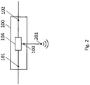
- figure 2 shows the schematic block diagram of figure 1 , wherein further details of the communication module 100 according to the invention are shown schematically.
- the third interface 103 optionally comprises a wireless interface 201.
- the control unit 104 is further adapted to send and/or receive information via the wireless interface 201.
- the statements made above apply to the protocols supported by the wireless interface 201 .
- figure 3 shows the schematic block diagram of figure 1 , wherein further details of the communication module 100 according to the invention are shown schematically.
- the third interface 103 optionally includes a sensor 301.
- the control unit 104 is also set up to receive sensor data from the sensor 301, to process it and to send it as processed sensor data via the first interface 101 and/or the second interface 102 .
- the communication module 100 may include both the wireless interface 201 and the sensor 301.
- the control unit 104 is set up to control both the wireless interface 201 and the sensor 301 in accordance with the manner described above or to send and/or receive data via the third interface 103 .
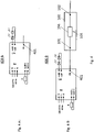
- figure 4 shows in Figure 4A and Figure 4B , Schematic block diagrams of preferred embodiments of lamp operating devices 400 A, 400 B according to the invention.
- the lamp operating device 400 A has a wired interface 401 which is set up to mechanically and functionally connect the lamp operating device 400 A to a first interface 101 of the communication module 100 .
- Figure 4B shows a lamp operating device 400 B, which has an optional communication module 100.
- the wired interface 401 of the lamp operating device 400 B is mechanically and functionally connected to the first wired interface 101 of the communication module 100 .
- figure 5 shows a schematic block diagram of a further example of a lamp operating device 500 according to the invention.
- Lamp operating device 500 shown comprises a communication module 100 according to the invention, as well as an optional, further communication module 100′ according to the invention.
- a first interface 101', a second interface 102', a third interface 103' and a control unit 104' together form the communication module 100'.
- the communication module 100' has identical features and functions as the communication module 100.
- figure 5 shows in particular the initially described, optional series connection or the "stack" of communication modules 100, 100'.
- the second interface 102 of the Communication module 100 connected to the first interface 101 'of the communication module 100'.
- the lamp operating device can also include further communication modules.
Landscapes
- Engineering & Computer Science (AREA)
- Computer Networks & Wireless Communication (AREA)
- Computer Security & Cryptography (AREA)
- Signal Processing (AREA)
- Circuit Arrangement For Electric Light Sources In General (AREA)
- Small-Scale Networks (AREA)
Description
- Die vorliegende Erfindung betrifft ein Kommunikationsmodul für ein Leuchtmittel-Betriebsgerät sowie ein Leuchtmittel-Betriebsgerät, aufweisend wenigstens ein solches erfindungsgemäßes Kommunikationsmodul. Das erfindungsgemäße Kommunikationsmodul ermöglicht Datenaustausch an einer ersten oder zweiten Schnittstelle mittels einem ersten Protokoll, und an einer dritten Schnittstelle, mittels einem von dem ersten Protokoll abweichenden Protokoll. An der zweiten und dritten Schnittstelle erfolgt Datenaustausch vorzugsweise mittels eines Internet of Things (IoT) Protokolls. Das erfindungsgemäße Kommunikations-modul ist derart ausgestaltet, dass eine modulare Reihenschaltung mehrerer solcher Kommunikationsmodule ermöglicht wird.
- Aus dem Stand der Technik sind Leuchtmittel-Betriebsgeräte, insbesondere light-emitting diode (LED) Betriebsgeräte oder LED-Konverter, bekannt, welche es erlauben an einer eingangsseitigen Schnittstelle Steuerungsinformationen (in Form von seriellen Informationen) entgegenzunehmen, und an einer ausgangsseitigen Schnittstelle zumindest ein (LED-) Leuchtmittel gemäß der Steuerungsinformationen mit elektrischer Energie zu versorgen und anzusteuern.
- Typischerweise nehmen die bekannten Leuchtmittel-Betriebsgeräte die Steuerungsinformationen eingangsseitig mittels des Protokolls ESI der Firma Enlighted oder auch des sehr ähnlichen Standards für vernetzte Lichttechnik "IoT-Ready" der IoT-Ready Alliance entgegen. Ebenfalls bekannt sind Leuchtmittel-Betriebsgeräte, welche eingangsseitig eines der Protokolle Digital Addressable Lighting Interface (DALI), Digital Serial Interface (DSI) oder Bluetooth Low Energy (BLE) unterstützen.
- Alle bekannten Leuchtmittel-Betriebsgeräten haben gemeinsam, dass sie jeweils nur über eine eingangsseitige Schnittstelle zum Empfang der Steuerungsinformationen verfügen und die eingangsseitige Schnittstelle auf eines der genannten Protokolle beschränkt ist. Den bekannten Leuchtmittel-Betriebsgeräten mangelt es ferner an einer Möglichkeit, selbstständig Steuerungsinformationen zu erheben und gemäß dieser Informationen die ausgangsseitige Schnittstelle anzusteuern.
-
US 2015/008846 A1 offenbart ein bekanntes Kommunikationsmodul in einem Beleuchtungssystem. -
WO 2015/104279 A1 undUS 2016/286628 A1 offenbaren jeweils bekannte Kommunikationsmodule für ein Leuchtmittel-Betriebsgerät. - In Anbetracht der aus dem Stand der Technik bekannten Lösungen ist es daher besonders nachteilig, dass die verbreiteten, auf dem Protokoll ESI basierenden, Leuchtmittel-Betriebsgeräte nicht auch mittels DALI, DSI, oder BLE basierter Steuerungsinformationen, oder beliebiger anderer protokollbasierter Steuerungsinformationen betrieben werden können. Insbesondere ist aus dem Stand der Technik kein Interface-Modul für ESI basierte Leuchtmittel-Betriebsgeräte bekannt, welches eines dieser gewünschten Protokolle unterstützt.
- Dies ist insbesondere nachteilig, da Aufgrund des allgemeinen Trends, individuelle Vorrichtungen miteinander zu vernetzen und diese durch Informations- und Kommunikationstechniken anzusteuern und zusammenwirken zu lassen (sogenanntes Internet der Dinge (IdD), oder IoT), auch der Wunsch nach Leuchtmittel-Betriebsgeräten besteht, welche eine flexible und vielseitige netzwerk- und protokollbasierte Ansteuerung erlauben. Um die bekannten Leuchtmittel-Betriebsgeräte flexibel und kostengünstig um individuell gewünschte, netzwerk- und protokollbasiere Funktionen erweitern zu können, besteht ferner ein Bedarf nach einer modularen Lösung.
- Folglich ist es eine Aufgabe der vorliegenden Erfindung, ein modulares Kommunikationsmodul bereitzustellen, welches ermöglicht, ein ESI basiertes Leuchtmittel-Steuergerät mittels einer Vielzahl von Protokollen über mehrere Schnittstellen anzusteuern.
- Diese und andere Aufgaben, die beim Lesen der folgenden Beschreibung noch genannt werden oder vom Fachmann erkannt werden können, werden durch den Gegenstand der unabhängigen Ansprüche gelöst. Die abhängigen Ansprüche bilden den zentralen Gedanken der vorliegenden Erfindung in besonders vorteilhafter Weise weiter.
- Gemäß der vorliegenden Erfindung wird ein Kommunikationsmodul für ein Leuchtmittel-Betriebsgerät bereitgestellt, welches eine erste drahtgebundene Schnittstelle, eine zweite drahtgebundene Schnittstelle, vorzugsweise eine dritte Schnittstelle, sowie eine Steuereinheit aufweist. Die erste drahtgebundene Schnittstelle ist mechanisch und funktionell verbindbar mit dem Leuchtmittel-Betriebsgerät oder einem weiteren Kommunikationsmodul ausgelegt, während die zweite drahtgebundene Schnittstelle, mechanisch und funktionell verbindbar mit einem Netzwerkelement oder einem weiteren Kommunikationsmodul ausgelegt ist. Die Steuereinheit ist mit der ersten Schnittstelle, der zweiten Schnittstelle und optional der dritten Schnittstelle verbunden und dazu eingerichtet, serielle Informationen gemäß einem ersten Protokoll über die erste oder zweite Schnittstellen zu empfangen, zu verarbeiten, und als verarbeitete serielle Informationen über zumindest eine der drei Schnittstellen zu senden. Das Kommunikationsmodul ist gemäß dem ersten Protokoll über die erste und/oder die zweite Schnittstelle mit einem weiteren Kommunikationsmodul in Reihe schaltbar.
- Die Steuereinheit ist vorzugsweise ferner dazu eingerichtet, Informationen über die dritte Schnittstelle gemäß einem zweiten, von dem ersten Protokoll abweichenden Protokoll zu senden und/oder zu empfangen.
- Mit anderen Worten schlägt die vorliegende Erfindung vor, dass einem Leuchtmittel-Betriebsgerät durch das Kommunikationsmodul über dessen erste, drahtgebundene Schnittstelle, Steuerungsinformationen zur Steuerung des Leuchtmittel-Betriebsgerätes gemäß einem ersten Protokoll zur Verfügung gestellt werden. Diese Steuerungsinformation werden von der Steuereinheit des Kommunikationsmoduls aus Informationen generiert, welche an der zweiten Schnittstelle des Kommunikationsmoduls gemäß dem ersten Protokoll und/oder optional an der dritten Schnittstelle des Kommunikationsmoduls gemäß dem zweiten, von dem ersten Protokoll verschiedenen Protokoll empfangen werden. Dabei können mehrere der erfindungsgemäßen Kommunikationsmodule kombiniert, also in Reihe geschaltet, bzw. verkettet (z.B. in einer sogenannten Daisy-Chain) oder gestapelt werden. So ist es möglich, modular aus mehreren Kommunikationsmodulen, welche jeweils z.B. zumindest ein bestimmtes Protokoll unterstützen oder z.B. eine bestimmte Ausprägung der dritten Schnittstelle aufweisen (z.B. als eine Drahtlosschnittstelle und/oder Sensorschnittstelle), einen Stapel, bzw. Stack an Kommunikationsmodulen zur Ansteuerung des Leuchtmittel-Betriebsgerätes bereitzustellen, welcher insgesamt eine Vielzahl an Protokollen und Funktionen unterstützt.
- Dies ist vorteilhaft, da somit eine Möglichkeit geschaffen wird, mit dem Leuchtmittel-Betriebsgerät mittels einer Vielzahl von Protokollen zu kommunizieren, und so dem Wunsch nach flexibler und vielseitiger netzwerk- und protokollbasierter Ansteuerung des Leuchtmittel-Betriebsgerätes entsprochen werden kann. Der modulare Aufbau erlaubt ferner eine vielseitig konfigurierbare und kostengünstige Lösung.
- Unter einem Leuchtmittel-Betriebsgerät ist vorzugsweise ein LED-Betriebsgerät, ferner vorzugsweise ein LED-Konverter zu verstehen.
- Unter einer Schnittstelle versteht man in diesem Zusammenhang vorzugsweise eine mechanische, und/oder elektronische, und/oder logische Verbindungsstelle zwischen Funktionseinheiten eines Datenverarbeitungs- oder -übertragungssystems, an welcher der Austausch von Daten, Informationen oder Steuersignalen erfolgt. Die Schnittstelle eignet sich daher sowohl zur mechanischen Verbindung bzw. Befestigung, als auch zur drahtlosen oder drahtgebundenen elektronischen Verbindung zum Austausch von Informationen (d.h. zur funktionellen oder logischen Verbindung). Drahtgebunden bedeutet vorzugsweise, dass Informationsaustausch mittels zumindest eines elektronischen Leiters erfolgt. Dies schließt zum Beispiel einen metallischen Leiter, aber auch einen optischen Faserleiter, z.B. eine Glasfaser, mit ein.
- Einem Netzwerkelement ist vorzugsweise eine Vorrichtung in einem Telekommunikations-oder Datenübertragungsnetz, z.B. eine Netzwerkleitung (inkl. Stecker oder Buchse), ein Hub, Switch, Router, Gateway oder Server. Grundsätzlich ist unter einem Netzwerkelement jedes Mittel zu verstehen, dass sich zum Generieren und/oder Übertragen von Informationen an das Kommunikationsmodul eignet.
- Die Steuereinheit weist vorzugsweise einen Mikrocontroller oder einen programmierbaren Prozessor auf.
- Unter dem Verarbeiten serieller Informationen durch die Steuereinheit ist vorzugsweise das Umwandeln der seriellen Informationen zu verstehen, so dass diese an einer sendenden Schnittstelle über ein anderes Protokoll gesendet werden, als das Protokoll, über das die seriellen Informationen an einer empfangenden Schnittstelle empfangen werden.
- Unter dem Verarbeiten serieller Informationen durch die Steuereinheit ist ferner vorzugsweise das Weiterleiten der seriellen Informationen zu verstehen, so dass diese an einer sendenden Schnittstelle über das selbe Protokoll gesendet werden, als das Protokoll, über das die seriellen Informationen an einer empfangenden Schnittstelle empfangen werden.
- Unter seriellen Informationen versteht man vorzugsweise sequentiell über zumindest ein Medium (z.B. über einen Leiter, eine Faser, oder mittels Funktechnologie) übertragene digitale Informationen, z.B. bit-weise übertragene Informationen.
- Vorzugsweise ist die Steuereinheit ferner dazu eingerichtet ist, serielle Informationen über die erste Schnittstelle und/oder die zweite Schnittstelle mittels eines IoT Protokolls, oder eines IoT-Ready Protokolls, oder mittels eines der Protokolle ESI, und/oder DALI, und/oder DSI, und/oder Thread, und/oder Universal Serial Bus, USB, zu senden und/oder zu empfangen.
- IdD (oder engl. IoT) ist ein Sammelbegriff für Technologien, die es ermöglichen, individuelle elektronische Vorrichtungen miteinander zu vernetzen und sie durch Informations- und Kommunikationstechniken zusammenwirken zu lassen. Als ein IoT Protokoll wird daher zunächst vorzugsweise jedes Kommunikationsprotokoll angesehen, das für den Austausch von Information zwischen Endpunkten bzw. Prozessen, die in einem Netzwerk miteinander verbunden sind (ein sogenanntes verteiltes System), geeignet ist - z.B. paketbasierte Protokolle. Insbesondere geeignet sind Protokolle der Internetprotokollfamilie (auch TCP/IP-Protokollfamilie genannt), welche eine Basis für die Netzwerkkommunikation im Internet bilden. Dazu zählen z.B. Ethernet mit CSMA/CD (IEEE 802.3), LAN, oder WLAN (IEEE 802.11), als Protokolle der Netzzugangsschicht; Internet Protocol (IP) zur verbindungslosen Datenpaket-Übertragung (in den Versionen IPv4 oder IPv6), oder Internet Protocol Security (IPSec) zur sicheren Datenpaket-Übertragung, beide als Protokolle der Internetschicht; Transmission Control Protocol (TCP) zur verbindungsorientierten, zuverlässigen Übertragung von Datenströmen, User Datagram Protocol (UDP) zur verbindungslosen, unzuverlässigen Übertragung von Datenpaketen, Transport Layer Security (TLS), eine Erweiterung von TCP um Verschlüsselung, als Protokolle der Transportschicht; Hypertext Transfer Protocol (HTTP), Hypertext Transfer Protocol Secure (HTTPS), Secure Shell (SSH), Secure Copy (SCP), oder Telnet als Protokolle der Anwendungsschicht.
- Bei dem IoT-Ready Protokoll handelt es sich vorzugsweise um ein Protokoll gemäß dem Standard für vernetzte Lichttechnik "IoT-Ready" der IoT-Ready Alliance.
- Bei Thread handelt es sich vorzugsweise um eine quelloffene, IPv6-basierte, stromsparende, sichere und zukunftssichere Mesh-Networking-Technologie für IoT-Produkte.
- Das USB Protokoll umfasst vorzugsweise die Versionen USB 1.0, USB 1.1, USB 2.0, USB 3.0, USB 3.1, USB 3.2.
- Dies ist vorteilhaft, da das Kommunikationsmodul so unter zumindest einem der bisher genannten Protokolle Informationen an der zweiten Schnittstelle empfangen kann, um diese dann in serielle Informationen, vorzugsweise ESI basierte Informationen, zu verarbeiten, welche an der ersten Schnittstelle zum Leuchtmittel-Betriebsgerät übertragen werden können. Dasselbe gilt für die entgegengensetzte Übertragungsrichtung.
- Vorzugsweise weist die zweite Schnittstelle ferner einen 0-10V Adapter oder einen 1-10V Adapter auf, und ist die Steuereinheit ferner dazu eingerichtet, serielle Informationen über den 0-10V Adapter oder den 1-10V Adapter zu senden und/oder zu empfangen.
- Dies ist vorteilhaft, da somit auch Informationen über den 0-10V Adapter bzw. den 1-10V Adapter an der zweiten Schnittstelle gesendet bzw. empfangen werden können, um auf diesen Informationen basierend das Leuchtmittel-Betriebsgerät zu steuern.
- Vorzugsweise umfasst die dritte Schnittstelle eine drahtlose Schnittstelle. Drahtlos bedeutet dabei vorzugsweise, dass die mittels der dritten Schnittstelle erfolgende elektronische Übertragung durch Funktechnologie erfolgt und nicht an Leitungen gebunden ist.
- Ein Vorteil dieser drahtlosen Schnittstelle liegt darin, dass man bei der Übertragung von Informationen mittels der dritten Schnittstelle nicht an leitungsbasierte Netzwerke gebunden ist und das Kommunikationsmodul flexibel platziert werden kann.
- Für den erfolgreichen Betrieb des Kommunikationsmoduls ist es insbesondere ausreichend, wenn Informationsübertragung entweder über die erste und zweite Schnittstelle, oder über die erste und dritte Schnittstelle erfolgt. D.h. ein Leuchtmittel-Betriebsgerät an der ersten Schnittstelle kann bereits dann mit Steuerinformationen versorgt werden, wenn das Kommunikationsmodul zusätzlich Informationen entweder über die zweite Schnittstelle, oder über die dritte Schnittstelle sendet oder empfängt. Das simultane Senden bzw. Empfangen von Informationen an der zweiten und dritten Schnittstelle ist zwar explizit möglich, aber nicht in jedem Anwendungsfall nötig.
- Vorzugsweise ist die Steuereinheit ferner dazu eingerichtet, Informationen über die drahtlose Schnittstelle mittels eines IoT Protokolls, oder eines IoT-Ready Protokolls, oder mittels eines der Protokolle Bluetooth, und/oder Bluetooth Low Energy, BLE, und/oder Wireless LAN, WLAN, und/oder Near Field Communication, NFC, und/oder Thread, und/oder ZigBee zu senden und/oder zu empfangen.
- Für das IoT Protokoll, das IoT-Ready Protokoll, sowie die weiteren, von der drahtlosen Schnittstelle unterstützten Protokolle gilt das zuvor gesagte.
- Das Kommunikationsmodul kann vorzugsweise über jede einzelne der drei Schnittstellen mit zumindest einem der bisher genannten Protokolle kommunizieren, damit bei modularer Verkettung bzw. modularer Reihenschaltung mehrere Kommunikationsmodule deren Informationsaustausch an der die Kommunikationsmodule verbindenden Schnittstelle gewährleistet ist. Das bedeutet zum Beispiel, dass das Kommunikationsmodul an der zweiten Schnittstelle Informationen mittels ESI, DALI oder DSI empfangen und diese an die erste Schnittstelle weiterleiten kann, und gleichzeitig an der dritten Schnittstelle Informationen mittels WLAN empfangen, diese zu ESI, DALI oder DSI-basierter Information umwandeln, und dann über die erste Schnittstelle senden kann. Dasselbe gilt für die umgekehrte Übertragungsrichtung bzw. Mischformen. Ferner ist eine beliebige Kombination aller genannten Protokolle zur Verwendung an den drei Schnittstellen möglich.
- Ferner vorzugsweise unterstützt das Kommunikationsmodul die simultane Verwendung unterschiedlicher Protokolle an unterschiedlichen Schnittstellen. So können zum Beispiel an der zweiten Schnittstelle gleichzeitig Informationen mittels DALI oder DSI, und TCP (vorzugsweise über IP, ferner vorzugsweise über HTTP) empfangen, in ESI umgewandelt, und über die erste Schnittstelle gesendet werden. Die Informationen können über die erste Schnittstelle nicht nur mittels ESI, sondern z.B. auch mittels DALI, DSI, TCP, IP, oder HTTP ausgegeben werden. Dasselbe gilt für die dritte Schnittstelle.
- Vorzugsweise umfasst die dritte Schnittstelle ferner einen Sensor, vorzugsweise einen optischen Sensor.
- Ein Sensor ist dabei insbesondere ein technisches Bauteil, das physikalische (z. B. Wärmemenge, Temperatur, Feuchtigkeit, Druck, Schallfeldgröße, Helligkeit, Beschleunigung) oder chemische (z. B. pH-Wert, Ionenstärke, elektrochemisches Potential) Eigenschaften und/oder die stoffliche Beschaffenheit seiner Umgebung qualitativ oder quantitativ als Messgröße erfassen und in ein verarbeitbares elektrisches Signal umformen kann.
- Ein optischer Sensor ist insbesondere ein elektronisches Bauelement, welches Licht unter Benutzung des photoelektrischen Effekts in ein elektrisches Signal umwandeln oder einen von der einfallenden Strahlung abhängigen elektrischen Widerstand zeigen kann, z.B. eine Photodiode, ein CCD-Sensor, ein CMOS-Sensor, oder eine elektronische Kamera.
- Dies hat den Vorteil, dass alternativ oder zusätzlich zu den an der zweiten Schnittstelle bereitgestellten Informationen, vom Kommunikationsmodul auch selbst Sensordaten erhoben und zur Steuerung (z.B. eines über die erste Schnittstelle verbundenen Leuchtmittel-Betriebsgerätes) verwendet werden können.
- Vorzugsweise ist die Steuereinheit ferner dazu eingerichtet, Sensordaten von dem Sensor zu empfangen, zu verarbeiten, und als verarbeitete Sensordaten über die erste Schnittstelle und/oder die zweite Schnittstelle zu senden.
- Dies hat den Vorteil, dass auch Sensordaten, welche z.B. in ESI-Informationen umgewandelt werden, zur Steuerung des Leuchtmittel-Betriebsgeräts über die erste Schnittstelle verwendet werden können. Alternativ oder zusätzlich können die Sensordaten auch mittels eins der zuvor genannten Protokolle über die zweite oder dritte Schnittstelle ausgegeben werden.
- Die dritte Schnittstelle kann dabei insbesondere sowohl den Sensor, als auch die drahtlose Schnittstelle umfassen. Das heißt, der Sensor, bzw. die drahtlose Schnittstelle können entweder als Alternativen, jedoch auch gleichzeitig in dem Kommunikationsmodul vorhanden sein. Sind sowohl der Sensor, als auch die drahtlose Schnittstelle in dem Kommunikationsmodul untergebracht, so ist die Steuereinheit ferner dazu eingerichtet, jeweils separat und unabhängig Sensordaten vom Sensor zu empfangen, sowie Informationen über die drahtlose Schnittstelle zu senden und/oder zu empfangen.
- Vorzugsweise ist die erste Schnittstelle und/oder die zweite Schnittstelle dazu eingerichtet, eine kraft- und/oder formschlüssige Verbindung mit dem Leuchtmittel-Betriebsgerät, dem Netzwerkelement, oder dem weiteren Kommunikationsmodul herzustellen, ferner vorzugsweise das Kommunikationsmodul an dem Leuchtmittel-Betriebsgerät, dem Netzwerkelement, oder dem weiteren Kommunikationsmodul stapelbar anzuordnen.
- Das bedeutet insbesondere, dass das Kommunikationsmodul mittels einer Steck-, Schraub-, oder Klemmverbindung mit dem Leuchtmittel-Betriebsgerät, dem Netzwerkelement (auch z.B. mit einem Netzwerkkabel), oder dem weiteren Kommunikationsmodul mechanisch sicher verbunden werden kann. Die kraft- und/oder formschlüssige Verbindung umfasst optional eine Zugentlastung, bzw. einen Bestandteil einer Zugentlastung, die von der ersten Schnittstelle und/oder der zweiten Schnittstelle umfasst ist.
- Dies ist insbesondere vorteilhaft, da auf diese Weise die Kommunikationsmodule als nebeneinander aufreihbare, modulare Elemente ausgebildet werden können. Ferner sind auch stapelbare, bzw. "stackable" Lösungen möglich, welche eine einfache Handhabung sicherstellen und den Platzbedarf reduzieren.
- Vorzugsweise sind die erste Schnittstelle und die zweite Schnittstelle als mechanisch zueinander korrespondierende Schnittstellen ausgebildet.
- Mechanisch zueinander korrespondierende Schnittstellen sind zum Beispiel Stecker und Buchse, Schraube und Mutter, sowie bei Klemmverbindungen die Klemme und das einzuklemmende Element (z.B. bei Fasern, insbesondere Glasfasern, als Leiter).
- Dies hat den Vorteil, dass die Handhabung der Herstellung der mechanischen Verbindung mehrerer Kommunikationsmodule erleichtert wird.
- Vorzugsweise umfasst die erste Schnittstelle eine RS-232 Schnittstelle zur Übertragung der Daten (also z.B. eine Schnittstelle die nach dem RS-232 Standard kommuniziert), ferner vorzugsweise eine RJ-45 Schnittstelle, insbesondere einen RJ45-Stecker, zur mechanischen und elektrischen Kontaktierung.
- Vorzugsweise umfasst die zweite Schnittstelle eine RS-232 Schnittstelle zur Übertragung der Daten (also z.B. eine Schnittstelle die nach dem RS-232 Standard kommuniziert), ferner vorzugsweise eine RJ-45 Schnittstelle, insbesondere eine RJ45-Buchse, zur mechanischen und elektrischen Kontaktierung.
- Dies hat den Vorteil, dass handelsübliches Netzwerkinstallationsmaterial, welches typischerweise RJ-45 Buchsen oder RJ-45 Stecker umfasst, zur Verkabelung bzw. Verbindung von Kommunikationsmodul, Netzwerkelement oder Leuchtmittel-Betriebsgerät verwendet werden kann.
- Vorzugsweise umfasst die zweite Schnittstelle eine USB-Schnittstelle. In Frage kommen dabei insbesondere eine USB-Buchse oder ein USB-Stecker. Diese können von normaler Größe, sowie vom Typ "mini" oder "micro" sein. Auf diese Weise kann das Kommunikationsmodul über die zweite Schnittstelle mit weiteren USB-Geräten kommunizieren, z.B. zur Programmierung durch einen Benutzer mittels eines Personal Computers (PC). Es ist insbesondere möglich, dass die erste Schnittstelle, und/oder die zweite Schnittstelle als USB Schnittstelle vorgesehen sind. Ist die erste Schnittstelle als USB Schnittstelle ausgestaltet, so kann das Kommunikationsmodul mit einem Leuchtmittel-Betriebsgerät, welches ebenfalls über eine USB-Schnittstelle verfügt, kommunizieren. Die zu übertragenden Informationen können dazu zur Übertragung im USB Protokoll gekapselt oder anderweitig enthalten sein.
- Vorzugsweise ist das Kommunikationsmodul ferner dazu eingerichtet, dass Informationsübertragung an der ersten Schnittstelle, und/oder der zweiten Schnittstelle, und/oder der dritten Schnittstelle bi-direktional erfolgt.
- Dies hat den Vorteil, dass an allen Schnittstellen Informationen gleichzeitig in beide Richtungen ausgetauscht werden können, und so die Effektivität der Datenübertragung erhöht wird.
- Vorzugsweise ist das Kommunikationsmodul ferner dazu eingerichtet, eine Versorgungsspannung an einer der drahtgebundenen Schnittstellen entgegenzunehmen und der Steuereinheit und/oder der jeweils anderen drahtgebundenen Schnittstelle bereitzustellen.
- Dies hat den Vorteil, dass so z.B. ein mit der zweiten Schnittstelle verbundenes Netzwerkelement, oder ein mit der zweiten Schnittstelle verbundenes weiteres Kommunikationsmodul, oder die Steuereinheit von dem Kommunikationsmodul mit einer Versorgungsspannung versorgt werden kann, welche wiederum dem Kommunikationsmodul über die erste Schnittstelle von einem Leuchtmittel-Betriebsgerät bereitgestellt wird. Eine entsprechende Übertragung der Versorgungsspannung von der zweiten Schnittstelle zur ersten Schnittstelle bzw. zur Steuereinheit ist ebenfalls möglich.
- Vorzugsweise ist das Kommunikationsmodul ferner dazu eingerichtet, die der Steuereinheit und/oder der jeweils anderen drahtgebundenen Schnittstelle bereitgestellte Versorgungsspannung zu begrenzen.
- Auf diese Weise kann die Versorgungsspannung, die vom Kommunikationsmodul an die Steuereinheit, bzw. vom Kommunikationsmodul an die erste oder zweite Schnittstelle bereitgestellt wird, bedarfsgerecht angepasst werden. Ferner kann so Schäden durch Überspannung vorgebeugt werden.
- Gemäß der vorliegenden Erfindung wird ferner ein Leuchtmittel-Betriebsgerät bereitgestellt, wobei das Leuchtmittel-Betriebsgerät eine drahtgebundene Schnittstelle, mechanisch und funktionell verbindbar mit dem Kommunikationsmodul gemäß einer der zuvor genannten Ausführungsformen umfasst.
- Mit anderen Worten ist das erfindungsgemäße Leuchtmittel-Betriebsgerät mittels dessen drahtgebundener Schnittstelle mechanisch mit der ersten Schnittstelle des Kommunikationsmoduls verbindbar, insbesondere mittels Kraft- und/oder Formschluss, z.B. durch eine Steck-, Schraub-, oder Klemmverbindung. Die funktionelle Kopplung kommt durch die Verbindung zumindest eines Leiters (aus Metall, bzw. als optische Faser) der Schnittstelle des Leuchtmittel-Betriebsgeräts mit einem korrespondierenden Leiter der ersten Schnittstelle des Kommunikationsmoduls zu Stande.
- Vorzugsweise umfasst das Leuchtmittelbetriebsgerät ferner zumindest ein Kommunikationsmodul nach einer der zuvor genannten Ausführungsformen. Es können insbesondere auch zwei, drei, oder weitere Kommunikationsmodule enthalten sein.
- Nachfolgend wird eine detaillierte Beschreibung der Figuren gegeben. Darin zeigt:
- Figur 1
- ein schematisches Blockschaltbild einer bevorzugten Ausführungsform eines erfindungsgemäßen Kommunikationsmoduls.
- Figur 2
- das schematische Blockschaltbild der
Figur 1 , wobei weitere Details des erfindungsgemäßen Kommunikationsmoduls schematisch gezeigt werden. - Figur 3
- das schematische Blockschaltbild der
Figur 1 , wobei weitere Details des erfindungsgemäßen Kommunikationsmoduls schematisch gezeigt werden. - Figur 4
- schematische Blockschaltbilder bevorzugter Ausführungsformen erfindungsgemäßer Leuchtmittel-Betriebsgeräte.
- Figur 5
- ein schematisches Blockschaltbild eines weiteren Beispiels eines erfindungsgemäßen Leuchtmittel-Betriebsgeräts.
- Sich entsprechende Elemente sind in den Figuren mit den gleichen Bezugszeichen markiert.
-
Figur 1 zeigt ein schematisches Blockschaltbild einer bevorzugten Ausführungsform eines erfindungsgemäßen Kommunikationsmoduls 100. - Die
Figur 1 zeigt schematisch eine erste drahtgebundene Schnittstelle 101, eine zweite drahtgebundene Schnittstelle 102, eine optionale dritte Schnittstelle 103 und eine Steuereinheit 104. Dabei ist die Steuereinheit 104 mit der ersten Schnittstelle 101, der zweiten Schnittstelle 102 und optional der dritten Schnittstelle 103 jeweils separat verbunden. Die erste Schnittstelle 101, die zweite Schnittstelle 102, die optionale dritte Schnittstelle 103 und die Steuereinheit 104 bilden zusammen das Kommunikationsmodul 100. - Wie in
Figur 1 dargestellt, ist die Steuereinheit 104 dazu eingerichtet, serielle Informationen gemäß einem ersten Protokoll über die erste oder zweite Schnittstelle 101, 102 zu empfangen, zu verarbeiten, und als verarbeitete serielle Informationen über zumindest eine der drei Schnittstellen 101, 102, 103 zu senden. - Die Steuereinheit 104 ist dabei vorzugsweise dazu eingerichtet ist, Informationen über die dritte Schnittstelle 103 gemäß einem zweiten, von dem ersten Protokoll abweichenden Protokoll zu senden und/oder zu empfangen.
- Für die Eigenschaften der ersten, zweiten und dritten Schnittstelle 101, 102, 103, sowie für die von den Schnittstellen 101, 102, 103 unterstützten Protokolle und Adapter gilt das zuvor gesagte. Insbesondere ist jede der Schnittstellen 101, 102, 103 grundsätzliche dazu geeignet, jedes der zuvor genannten Protokolle zu verwenden.
- Die erste Schnittstelle 101 und / oder die zweite Schnittstelle 102 können zur mechanischen Kontaktierung einer kraft- und/oder formschlüssige Verbindung eine Zugentlastung, bzw. einen Bestandteil einer Zugentlastung umfassen.
-
Figur 2 zeigt das schematische Blockschaltbild derFigur 1 , wobei weitere Details des erfindungsgemäßen Kommunikationsmoduls 100 schematisch gezeigt werden. - Wie in
Figur 2 gezeigt, umfasst die dritte Schnittstelle 103 optional eine drahtlose Schnittstelle 201. Die Steuereinheit 104 ist ferner dazu angepasst, Informationen über die drahtlose Schnittstelle 201 zu senden und/oder zu empfangen. Für die dabei von der drahtlosen Schnittstelle 201 unterstützten Protokolle gilt das zuvor gesagte. -
Figur 3 zeigt das schematische Blockschaltbild derFigur 1 , wobei weitere Details des erfindungsgemäßen Kommunikationsmoduls 100 schematisch gezeigt werden. - Wie in
Figur 3 gezeigt, umfasst hier die dritte Schnittstelle 103 optional einen Sensor 301. Die Steuereinheit 104 ist ferner dazu eingerichtet, Sensordaten von dem Sensor 301 zu empfangen, zu verarbeiten, und als verarbeitete Sensordaten über die erste Schnittstelle 101 und/oder die zweite Schnittstelle 102 zu senden. - Obwohl dies in den
Figuren 1 ,2 und3 nicht gezeigt ist, kann das Kommunikationsmodul 100 sowohl die drahtlose Schnittstelle 201, als auch den Sensor 301 enthalten. Die Steuereinheit 104 ist in diesem Fall dazu eingerichtet, sowohl die drahtlose Schnittstelle 201 als auch den Sensor 301 gemäß der oben beschriebenen Weise zu steuern bzw. Daten über die dritte Schnittstelle 103 zu senden und/oder zu empfangen. -
Figur 4 zeigt, inFigur 4 A und Figur 4 B , schematische Blockschaltbilder bevorzugter Ausführungsformen erfindungsgemäßer Leuchtmittel-Betriebsgeräte 400 A, 400 B. - Wie in
Figur 4 A gezeigt, hat das Leuchtmittel-Betriebsgerät 400 A eine drahtgebundene Schnittstelle 401, welche dazu eingerichtet ist, das Leuchtmittel-Betriebsgerät 400 A mechanisch und funktionell mit einer ersten Schnittstelle 101 des Kommunikationsmoduls 100 zu verbinden. -
Figur 4 B zeigt ein Leuchtmittel-Betriebsgerät 400 B, welches ein optionales Kommunikationsmodul 100 aufweist. Dazu ist die drahtgebundene Schnittstelle 401 des Leuchtmittel-Betriebsgerätes 400 B mit der ersten drahtgebundenen Schnittstelle 101 des Kommunikationsmoduls 100 mechanisch und funktional verbunden. -
Figur 5 zeigt ein schematisches Blockschaltbild eines weiteren Beispiels eines erfindungsgemäßen Leuchtmittel-Betriebsgeräts 500. - Das in
Figur 5 gezeigte Leuchtmittel-Betriebsgerät 500 umfasst ein erfindungsgemäßes Kommunikationsmodul 100, sowie ein optionales, weiteres erfindungsgemäßes Kommunikationsmodul 100'. - Dabei bilden eine erste Schnittstelle 101', eine zweite Schnittstelle 102', eine dritte Schnittstelle 103' und eine Steuereinheit 104' zusammen das Kommunikationsmodul 100'. Das Kommunikationsmodul 100' verfügt über identische Merkmale und Funktionen wie das Kommunikationsmodul 100.
-
Figur 5 zeigt insbesondere die eingangs beschriebene, optionale Reihenschaltung, bzw. den "Stack" von Kommunikationsmodulen 100, 100'. Dazu ist die zweite Schnittstelle 102 des Kommunikationsmoduls 100 mit der ersten Schnittstelle 101' des Kommunikationsmoduls 100' verbunden. - Obwohl in
Figur 5 nur zwei Kommunikationsmodule 100, 100` gezeigt sind, kann das Leuchtmittel-Betriebsgerät auch weitere Kommunikationsmodule umfassen.
Claims (15)
- Kommunikationsmodul (100) für ein Leuchtmittel-Betriebsgerät, wobei das Kommunikationsmodul (100) aufweist:- eine erste drahtgebundene Schnittstelle (101), mechanisch und funktionell verbindbar mit dem Leuchtmittel-Betriebsgerät oder einem weiteren Kommunikationsmodul,- eine zweite drahtgebundene Schnittstelle (102), mechanisch und funktionell verbindbar mit einem Netzwerkelement oder einem weiteren Kommunikationsmodul,- vorzugsweise eine dritte Schnittstelle (103), und- eine Steuereinheit (104), verbunden mit der ersten Schnittstelle (101), der zweiten Schnittstelle (102) und optional der dritten Schnittstelle (103),wobei die Steuereinheit (104) dazu eingerichtet ist, serielle Informationen gemäß einem ersten Protokoll über die erste und/oder die zweite Schnittstelle (101, 102) zu empfangen, zu verarbeiten, und als verarbeitete serielle Informationen über zumindest eine der drei Schnittstellen (101, 102, 103) zu senden,wobei das Kommunikationsmodul (100) gemäß dem ersten Protokoll über die erste und/oder die zweite Schnittstelle (101, 102) mit einem weiteren Kommunikationsmodul in Reihe schaltbar ist, undwobei es sich bei dem Kommunikationsmodul (100) und dem weiteren Kommunikationsmodul um gleichartige Kommunikationsmodule handelt,dadurch gekennzeichnet, dassdas Kommunikationsmodul (100) ferner dazu eingerichtet ist, dass es an der ersten drahtgebundenen Schnittstelle (101) wahlweise sowohl mit dem Leuchtmittel-Betriebsgerät als auch dem weiteren Kommunikationsmodul verbindbar ist.
- Kommunikationsmodul (100) gemäß Anspruch 1, wobei das Kommunikationsmodul (100) die dritte Schnittstelle (103) umfasst, und
wobei die Steuereinheit (104) ferner dazu eingerichtet ist, Informationen über die dritte Schnittstelle (103) gemäß einem zweiten, von dem ersten Protokoll abweichenden Protokoll zu senden und/oder zu empfangen. - Kommunikationsmodul (100) gemäß Anspruch 1 oder 2, wobei die Steuereinheit (104) ferner dazu eingerichtet ist, serielle Informationen über die erste Schnittstelle (101) und/oder die zweite Schnittstelle (102) mittels eines Internet of Things, IoT, Protokolls, oder eines IoT-Ready Protokolls, oder mittels eines der Protokolle ESI, und/oder Digital Addressable Lighting Interface, DALI, und/oder Digital Serial Interface, DSI, und/oder Universal Serial Bus, USB, zu senden und/oder zu empfangen.
- Kommunikationsmodul (100) gemäß einem der vorhergehenden Ansprüche, wobei die zweite Schnittstelle (102) ferner einen 0-10V Adapter oder einen 1-10V Adapter umfasst, und die Steuereinheit (104) ferner dazu eingerichtet ist, serielle Informationen über den 0-10V Adapter oder den 1-10V Adapter zu senden und/oder zu empfangen.
- Kommunikationsmodul (100) gemäß einem der vorhergehenden Ansprüche, wobei das Kommunikationsmodul (100) die dritte Schnittstelle (103) umfasst, und wobei die dritte Schnittstelle (103) eine drahtlose Schnittstelle (201) umfasst wobei die Steuereinheit (104) vorzugsweise ferner dazu eingerichtet ist, Informationen über die drahtlose Schnittstelle (201) mittels eines IoT Protokolls, oder eines IoT-Ready Protokolls, oder mittels eines der Protokolle Bluetooth, und/oder Bluetooth Low Energy, BLE, und/oder Wireless LAN, WLAN, und/oder Near Field Communication, NFC, und/oder Thread, und/oder ZigBee zu senden und/oder zu empfangen.
- Kommunikationsmodul (100) gemäß einem der vorhergehenden Ansprüche, wobei das Kommunikationsmodul (100) die dritte Schnittstelle (103) umfasst, und wobei die dritte Schnittstelle ferner einen Sensor (301), vorzugsweise einen optischen Sensor, umfasst.
- Kommunikationsmodul (100) gemäß Anspruch 6, wobei die Steuereinheit (104) ferner dazu eingerichtet ist, Sensordaten von dem Sensor (301) zu empfangen, zu verarbeiten, und als verarbeitete serielle Sensordaten über die erste Schnittstelle (101) und/oder die zweite Schnittstelle (102) zu senden.
- Kommunikationsmodul (100) gemäß einem der vorhergehenden Ansprüche, wobei die erste Schnittstelle (101) und/oder die zweite Schnittstelle (102) dazu eingerichtet sind, eine kraft- und/oder formschlüssige Verbindung mit dem Leuchtmittel-Betriebsgerät, dem Netzwerkelement, oder dem weiteren Kommunikationsmodul herzustellen, und vorzugsweise das Kommunikationsmodul (100) an dem Leuchtmittel-Betriebsgerät, dem Netzwerkelement, oder dem weiteren Kommunikationsmodul stapelbar anzuordnen.
- Kommunikationsmodul (100) gemäß einem der vorhergehenden Ansprüche, wobei die erste Schnittstelle (101) und die zweite Schnittstelle (102) als mechanisch zueinander korrespondierende Schnittstellen ausgebildet sind.
- Kommunikationsmodul (100) gemäß einem der vorhergehenden Ansprüche, wobei die erste Schnittstelle (101) einen RJ45-Stecker, umfasst.
- Kommunikationsmodul (100) gemäß einem der Ansprüche 1 bis 10, wobei die zweite Schnittstelle (102) eine RJ45-Buchse, umfasst.
- Kommunikationsmodul (100) gemäß einem der Ansprüche 1 bis 9, wobei die zweite Schnittstelle (102) eine USB-Schnittstelle umfasst.
- Kommunikationsmodul (100) gemäß einem der vorhergehenden Ansprüche, wobei das Kommunikationsmodul (100) ferner dazu eingerichtet ist, dass Informationsübertragung an der ersten Schnittstelle (101), und/oder der zweiten Schnittstelle (102), und/oder der dritten Schnittstelle (103), sofern das Kommunikationsmodul (100) die dritte Schnittstelle aufweist, bi-direktional erfolgt.
- Kommunikationsmodul (100) gemäß einem der vorhergehenden Ansprüche, wobei in der Steuereinheit (104) Betriebsinformationen oder Steuerparamater für den Betrieb des Leuchtmittel-Betriebsgerätes (400A) abgespeichert sind und es dazu eingerichtet ist, serielle Informationen gemäß dem ersten Protokoll über die erste und/oder die zweite Schnittstelle (101, 102) zu senden.
- Leuchtmittel-Betriebsgerät (400 A), aufweisend:- eine drahtgebundene Schnittstelle (401), mechanisch und funktionell verbindbar mit dem Kommunikationsmodul (100) nach einem der Ansprüche 1 bis 14, und- zumindest ein Kommunikationsmodul (100) nach einem der Ansprüche 1 bis 14.
Applications Claiming Priority (2)
| Application Number | Priority Date | Filing Date | Title |
|---|---|---|---|
| DE202018102367.5U DE202018102367U1 (de) | 2018-04-27 | 2018-04-27 | Kommunikationsmodul für ein Leuchtmittel-Betriebsgerät |
| PCT/EP2019/060021 WO2019206782A1 (de) | 2018-04-27 | 2019-04-17 | Kommunikationsmodul für ein leuchtmittel-betriebsgerät |
Publications (2)
| Publication Number | Publication Date |
|---|---|
| EP3769589A1 EP3769589A1 (de) | 2021-01-27 |
| EP3769589B1 true EP3769589B1 (de) | 2023-01-25 |
Family
ID=66379880
Family Applications (1)
| Application Number | Title | Priority Date | Filing Date |
|---|---|---|---|
| EP19721222.8A Active EP3769589B1 (de) | 2018-04-27 | 2019-04-17 | Kommunikationsmodul für ein leuchtmittel-betriebsgerät |
Country Status (4)
| Country | Link |
|---|---|
| EP (1) | EP3769589B1 (de) |
| AT (1) | AT17782U1 (de) |
| DE (1) | DE202018102367U1 (de) |
| WO (1) | WO2019206782A1 (de) |
Families Citing this family (2)
| Publication number | Priority date | Publication date | Assignee | Title |
|---|---|---|---|---|
| DE102020117446A1 (de) * | 2020-07-02 | 2022-01-05 | Zumtobel Lighting Gmbh | Vorrichtung mit multifunktionalem Anschluss für Nicht-DALI-Bediengeräte |
| DE102022210455A1 (de) * | 2022-09-30 | 2024-04-04 | Inventronics Gmbh | System zur beleuchtungssteuerung |
Family Cites Families (13)
| Publication number | Priority date | Publication date | Assignee | Title |
|---|---|---|---|---|
| US7483964B1 (en) * | 2000-02-25 | 2009-01-27 | Nortel Networks, Limited | System, device, and method for providing personalized services in a communication system |
| DE102005028206B4 (de) * | 2005-06-17 | 2018-05-17 | Tridonic Gmbh & Co Kg | Ermittlung der Busadresse eines Teilnehmers in einem Beleuchtungs-Bussystem |
| US9335750B2 (en) * | 2011-10-04 | 2016-05-10 | Advanergy, Inc. | Light fixture adapter (LFA) security monitoring |
| US20140197758A1 (en) * | 2013-01-16 | 2014-07-17 | Cree, Inc. | Power supply with interface and embedded configuration information |
| TWI513371B (zh) * | 2013-07-08 | 2015-12-11 | Lextar Electronics Corp | 整合無線暨有線的照明控制系統 |
| DE102014200297B4 (de) * | 2014-01-10 | 2025-03-27 | Tridonic Gmbh & Co Kg | Betriebsgerät und Kommunikationsadapter für den Außeneinsatz |
| GB201405570D0 (en) * | 2014-03-27 | 2014-05-14 | Aurora Ltd | Improved control module |
| US9655213B2 (en) * | 2015-03-27 | 2017-05-16 | Cooper Technologies Company | Modular wireless lighting control |
| US9474132B1 (en) * | 2015-06-19 | 2016-10-18 | Uniform Industrial Corp. | Light control device and system, and method of light control |
| KR101786290B1 (ko) * | 2016-01-08 | 2017-10-18 | 디노플러스 (주) | 스마트 홈 구현을 위한 통합 게이트웨이장치 |
| US9726332B1 (en) * | 2016-02-09 | 2017-08-08 | Michael W. May | Networked LED lighting system |
| WO2017151682A1 (en) * | 2016-02-29 | 2017-09-08 | Innosys, Inc. | Switched Wireless Signaling |
| EP3217601B1 (de) * | 2016-03-11 | 2021-05-05 | Tridonic GmbH & Co KG | Iot-kommunikationsmodul für eine gebäudetechnische vorrichtung, gebäudetechnische vorrichtung für iot-netzwerke, gebäudetechnisches kommunikationssystem und gebäudetechnisches verwaltungssystem |
-
2018
- 2018-04-27 DE DE202018102367.5U patent/DE202018102367U1/de not_active Expired - Lifetime
- 2018-12-04 AT ATGM50222/2018U patent/AT17782U1/de not_active IP Right Cessation
-
2019
- 2019-04-17 WO PCT/EP2019/060021 patent/WO2019206782A1/de not_active Ceased
- 2019-04-17 EP EP19721222.8A patent/EP3769589B1/de active Active
Also Published As
| Publication number | Publication date |
|---|---|
| DE202018102367U1 (de) | 2019-07-30 |
| EP3769589A1 (de) | 2021-01-27 |
| AT17782U1 (de) | 2023-02-15 |
| WO2019206782A1 (de) | 2019-10-31 |
Similar Documents
| Publication | Publication Date | Title |
|---|---|---|
| DE102011006668B3 (de) | Schnittstellenmodul für ein modulares Steuerungsgerät | |
| AT17524U1 (de) | Kommunikationsmodul und Beleuchtungs-Bussystem mit Netzwerkschnittstelle | |
| DE102019127195A1 (de) | Modulares Interfacesystem zum Anschließen einer Steuerungseinrichtung und von Feldgeräte | |
| EP2988183A1 (de) | Fernwirkanordnung, system und verfahren zum beobachten und/oder steuern einer anlage | |
| EP2456133A1 (de) | Modularer Schalt-Netzknoten für ein Kommunikationsnetzwerk | |
| DE102013100139A1 (de) | Prozessdaten-Gateway in einem dezentralen Automatisierungssystem auf Basis der Webtechnologie | |
| EP3769589A1 (de) | Kommunikationsmodul für ein leuchtmittel-betriebsgerät | |
| DE102005062579A1 (de) | Vorrichtung zum drahtlosen Datenaustausch sowie Verfahren zum Aufbau einer drahtlosen Verbindung zwischen einer insbesondere medizinischen Sensoreinheit und einer Rechnereinheit | |
| EP2400708B1 (de) | Netzwerk-Schutzeinrichtung | |
| EP3977702B1 (de) | Netzwerkadapter zur unidirektionalen übertragung von daten | |
| DE102021212976A1 (de) | Authentifizierung und steuerung einer datenspur | |
| DE102014112704B3 (de) | Netzwerksystem und Netzwerkteilnehmer zur Datenübertragung über eine Cloud-Infrastruktur und Verfahren zur Einrichtung | |
| BE1027224B1 (de) | Modularer Switch zum Einsatz in einem Datenübertragungs- und Steuerungssystem | |
| EP2506503B1 (de) | Automatisierungsnetzwerk mit Leitsystemkomponente | |
| EP4677814A1 (de) | Vermittler und automatisierungssystem | |
| DE102015116927A1 (de) | Vorrichtung zur Datenübertragung | |
| DE102019112007A1 (de) | Steckverbinder | |
| EP1645098A1 (de) | Vorrichtung und koppelgerät, so genannter secure-switch, zur sicherung eines datenzugriffes | |
| EP4152895A1 (de) | Beleuchtungssystem | |
| DE102011003309A1 (de) | Netzwerkknoten und Energieversorgungungsmodul für ein Automatisierungsnetzwerk | |
| DE10331309A1 (de) | Vorrichtung und Koppelgerät, so genannter transparenter Tunnel-Proxy, zur Sicherung eines Datenzugriffs | |
| DE102014201007A1 (de) | Netzwerkzugangsvorrichtung | |
| DE102024105538A1 (de) | Adressvergabeverfahren in einem kommunikationsnetzwerk | |
| DE102007013995B4 (de) | Signalverteiler | |
| DE102007013379B4 (de) | Netzwerkabschluß zum Anschluß an eine Busleitung |
Legal Events
| Date | Code | Title | Description |
|---|---|---|---|
| STAA | Information on the status of an ep patent application or granted ep patent |
Free format text: STATUS: UNKNOWN |
|
| STAA | Information on the status of an ep patent application or granted ep patent |
Free format text: STATUS: THE INTERNATIONAL PUBLICATION HAS BEEN MADE |
|
| PUAI | Public reference made under article 153(3) epc to a published international application that has entered the european phase |
Free format text: ORIGINAL CODE: 0009012 |
|
| STAA | Information on the status of an ep patent application or granted ep patent |
Free format text: STATUS: REQUEST FOR EXAMINATION WAS MADE |
|
| 17P | Request for examination filed |
Effective date: 20201022 |
|
| AK | Designated contracting states |
Kind code of ref document: A1 Designated state(s): AL AT BE BG CH CY CZ DE DK EE ES FI FR GB GR HR HU IE IS IT LI LT LU LV MC MK MT NL NO PL PT RO RS SE SI SK SM TR |
|
| AX | Request for extension of the european patent |
Extension state: BA ME |
|
| DAV | Request for validation of the european patent (deleted) | ||
| DAX | Request for extension of the european patent (deleted) | ||
| STAA | Information on the status of an ep patent application or granted ep patent |
Free format text: STATUS: EXAMINATION IS IN PROGRESS |
|
| 17Q | First examination report despatched |
Effective date: 20220322 |
|
| REG | Reference to a national code |
Ref country code: DE Ref legal event code: R079 Ref document number: 502019006870 Country of ref document: DE Free format text: PREVIOUS MAIN CLASS: H05B0037020000 Ipc: H05B0047190000 |
|
| GRAP | Despatch of communication of intention to grant a patent |
Free format text: ORIGINAL CODE: EPIDOSNIGR1 |
|
| STAA | Information on the status of an ep patent application or granted ep patent |
Free format text: STATUS: GRANT OF PATENT IS INTENDED |
|
| RIC1 | Information provided on ipc code assigned before grant |
Ipc: H04L 12/66 20060101ALI20220926BHEP Ipc: H04L 69/18 20220101ALI20220926BHEP Ipc: H04L 69/08 20220101ALI20220926BHEP Ipc: H05B 47/18 20200101ALI20220926BHEP Ipc: H05B 47/105 20200101ALI20220926BHEP Ipc: H05B 47/19 20200101AFI20220926BHEP |
|
| INTG | Intention to grant announced |
Effective date: 20221102 |
|
| GRAS | Grant fee paid |
Free format text: ORIGINAL CODE: EPIDOSNIGR3 |
|
| GRAA | (expected) grant |
Free format text: ORIGINAL CODE: 0009210 |
|
| STAA | Information on the status of an ep patent application or granted ep patent |
Free format text: STATUS: THE PATENT HAS BEEN GRANTED |
|
| AK | Designated contracting states |
Kind code of ref document: B1 Designated state(s): AL AT BE BG CH CY CZ DE DK EE ES FI FR GB GR HR HU IE IS IT LI LT LU LV MC MK MT NL NO PL PT RO RS SE SI SK SM TR |
|
| REG | Reference to a national code |
Ref country code: GB Ref legal event code: FG4D Free format text: NOT ENGLISH |
|
| REG | Reference to a national code |
Ref country code: CH Ref legal event code: EP |
|
| REG | Reference to a national code |
Ref country code: AT Ref legal event code: REF Ref document number: 1546667 Country of ref document: AT Kind code of ref document: T Effective date: 20230215 Ref country code: IE Ref legal event code: FG4D Free format text: LANGUAGE OF EP DOCUMENT: GERMAN |
|
| REG | Reference to a national code |
Ref country code: DE Ref legal event code: R096 Ref document number: 502019006870 Country of ref document: DE |
|
| REG | Reference to a national code |
Ref country code: LT Ref legal event code: MG9D |
|
| REG | Reference to a national code |
Ref country code: NL Ref legal event code: MP Effective date: 20230125 |
|
| PG25 | Lapsed in a contracting state [announced via postgrant information from national office to epo] |
Ref country code: NL Free format text: LAPSE BECAUSE OF FAILURE TO SUBMIT A TRANSLATION OF THE DESCRIPTION OR TO PAY THE FEE WITHIN THE PRESCRIBED TIME-LIMIT Effective date: 20230125 |
|
| P01 | Opt-out of the competence of the unified patent court (upc) registered |
Effective date: 20230530 |
|
| PG25 | Lapsed in a contracting state [announced via postgrant information from national office to epo] |
Ref country code: RS Free format text: LAPSE BECAUSE OF FAILURE TO SUBMIT A TRANSLATION OF THE DESCRIPTION OR TO PAY THE FEE WITHIN THE PRESCRIBED TIME-LIMIT Effective date: 20230125 Ref country code: PT Free format text: LAPSE BECAUSE OF FAILURE TO SUBMIT A TRANSLATION OF THE DESCRIPTION OR TO PAY THE FEE WITHIN THE PRESCRIBED TIME-LIMIT Effective date: 20230525 Ref country code: NO Free format text: LAPSE BECAUSE OF FAILURE TO SUBMIT A TRANSLATION OF THE DESCRIPTION OR TO PAY THE FEE WITHIN THE PRESCRIBED TIME-LIMIT Effective date: 20230425 Ref country code: LV Free format text: LAPSE BECAUSE OF FAILURE TO SUBMIT A TRANSLATION OF THE DESCRIPTION OR TO PAY THE FEE WITHIN THE PRESCRIBED TIME-LIMIT Effective date: 20230125 Ref country code: LT Free format text: LAPSE BECAUSE OF FAILURE TO SUBMIT A TRANSLATION OF THE DESCRIPTION OR TO PAY THE FEE WITHIN THE PRESCRIBED TIME-LIMIT Effective date: 20230125 Ref country code: HR Free format text: LAPSE BECAUSE OF FAILURE TO SUBMIT A TRANSLATION OF THE DESCRIPTION OR TO PAY THE FEE WITHIN THE PRESCRIBED TIME-LIMIT Effective date: 20230125 Ref country code: ES Free format text: LAPSE BECAUSE OF FAILURE TO SUBMIT A TRANSLATION OF THE DESCRIPTION OR TO PAY THE FEE WITHIN THE PRESCRIBED TIME-LIMIT Effective date: 20230125 |
|
| PG25 | Lapsed in a contracting state [announced via postgrant information from national office to epo] |
Ref country code: SE Free format text: LAPSE BECAUSE OF FAILURE TO SUBMIT A TRANSLATION OF THE DESCRIPTION OR TO PAY THE FEE WITHIN THE PRESCRIBED TIME-LIMIT Effective date: 20230125 Ref country code: PL Free format text: LAPSE BECAUSE OF FAILURE TO SUBMIT A TRANSLATION OF THE DESCRIPTION OR TO PAY THE FEE WITHIN THE PRESCRIBED TIME-LIMIT Effective date: 20230125 Ref country code: IS Free format text: LAPSE BECAUSE OF FAILURE TO SUBMIT A TRANSLATION OF THE DESCRIPTION OR TO PAY THE FEE WITHIN THE PRESCRIBED TIME-LIMIT Effective date: 20230525 Ref country code: GR Free format text: LAPSE BECAUSE OF FAILURE TO SUBMIT A TRANSLATION OF THE DESCRIPTION OR TO PAY THE FEE WITHIN THE PRESCRIBED TIME-LIMIT Effective date: 20230426 Ref country code: FI Free format text: LAPSE BECAUSE OF FAILURE TO SUBMIT A TRANSLATION OF THE DESCRIPTION OR TO PAY THE FEE WITHIN THE PRESCRIBED TIME-LIMIT Effective date: 20230125 |
|
| REG | Reference to a national code |
Ref country code: DE Ref legal event code: R097 Ref document number: 502019006870 Country of ref document: DE |
|
| PG25 | Lapsed in a contracting state [announced via postgrant information from national office to epo] |
Ref country code: SM Free format text: LAPSE BECAUSE OF FAILURE TO SUBMIT A TRANSLATION OF THE DESCRIPTION OR TO PAY THE FEE WITHIN THE PRESCRIBED TIME-LIMIT Effective date: 20230125 Ref country code: RO Free format text: LAPSE BECAUSE OF FAILURE TO SUBMIT A TRANSLATION OF THE DESCRIPTION OR TO PAY THE FEE WITHIN THE PRESCRIBED TIME-LIMIT Effective date: 20230125 Ref country code: EE Free format text: LAPSE BECAUSE OF FAILURE TO SUBMIT A TRANSLATION OF THE DESCRIPTION OR TO PAY THE FEE WITHIN THE PRESCRIBED TIME-LIMIT Effective date: 20230125 Ref country code: DK Free format text: LAPSE BECAUSE OF FAILURE TO SUBMIT A TRANSLATION OF THE DESCRIPTION OR TO PAY THE FEE WITHIN THE PRESCRIBED TIME-LIMIT Effective date: 20230125 Ref country code: CZ Free format text: LAPSE BECAUSE OF FAILURE TO SUBMIT A TRANSLATION OF THE DESCRIPTION OR TO PAY THE FEE WITHIN THE PRESCRIBED TIME-LIMIT Effective date: 20230125 |
|
| PG25 | Lapsed in a contracting state [announced via postgrant information from national office to epo] |
Ref country code: SK Free format text: LAPSE BECAUSE OF FAILURE TO SUBMIT A TRANSLATION OF THE DESCRIPTION OR TO PAY THE FEE WITHIN THE PRESCRIBED TIME-LIMIT Effective date: 20230125 |
|
| PLBE | No opposition filed within time limit |
Free format text: ORIGINAL CODE: 0009261 |
|
| STAA | Information on the status of an ep patent application or granted ep patent |
Free format text: STATUS: NO OPPOSITION FILED WITHIN TIME LIMIT |
|
| PG25 | Lapsed in a contracting state [announced via postgrant information from national office to epo] |
Ref country code: LU Free format text: LAPSE BECAUSE OF NON-PAYMENT OF DUE FEES Effective date: 20230417 |
|
| 26N | No opposition filed |
Effective date: 20231026 |
|
| REG | Reference to a national code |
Ref country code: BE Ref legal event code: MM Effective date: 20230430 |
|
| PG25 | Lapsed in a contracting state [announced via postgrant information from national office to epo] |
Ref country code: MC Free format text: LAPSE BECAUSE OF FAILURE TO SUBMIT A TRANSLATION OF THE DESCRIPTION OR TO PAY THE FEE WITHIN THE PRESCRIBED TIME-LIMIT Effective date: 20230125 |
|
| PG25 | Lapsed in a contracting state [announced via postgrant information from national office to epo] |
Ref country code: SI Free format text: LAPSE BECAUSE OF FAILURE TO SUBMIT A TRANSLATION OF THE DESCRIPTION OR TO PAY THE FEE WITHIN THE PRESCRIBED TIME-LIMIT Effective date: 20230125 Ref country code: MC Free format text: LAPSE BECAUSE OF FAILURE TO SUBMIT A TRANSLATION OF THE DESCRIPTION OR TO PAY THE FEE WITHIN THE PRESCRIBED TIME-LIMIT Effective date: 20230125 |
|
| REG | Reference to a national code |
Ref country code: IE Ref legal event code: MM4A |
|
| REG | Reference to a national code |
Ref country code: DE Ref legal event code: R084 Ref document number: 502019006870 Country of ref document: DE |
|
| PG25 | Lapsed in a contracting state [announced via postgrant information from national office to epo] |
Ref country code: BE Free format text: LAPSE BECAUSE OF NON-PAYMENT OF DUE FEES Effective date: 20230430 |
|
| PG25 | Lapsed in a contracting state [announced via postgrant information from national office to epo] |
Ref country code: IE Free format text: LAPSE BECAUSE OF NON-PAYMENT OF DUE FEES Effective date: 20230417 |
|
| PG25 | Lapsed in a contracting state [announced via postgrant information from national office to epo] |
Ref country code: IE Free format text: LAPSE BECAUSE OF NON-PAYMENT OF DUE FEES Effective date: 20230417 |
|
| PG25 | Lapsed in a contracting state [announced via postgrant information from national office to epo] |
Ref country code: IT Free format text: LAPSE BECAUSE OF FAILURE TO SUBMIT A TRANSLATION OF THE DESCRIPTION OR TO PAY THE FEE WITHIN THE PRESCRIBED TIME-LIMIT Effective date: 20230125 |
|
| PG25 | Lapsed in a contracting state [announced via postgrant information from national office to epo] |
Ref country code: BG Free format text: LAPSE BECAUSE OF FAILURE TO SUBMIT A TRANSLATION OF THE DESCRIPTION OR TO PAY THE FEE WITHIN THE PRESCRIBED TIME-LIMIT Effective date: 20230125 |
|
| PG25 | Lapsed in a contracting state [announced via postgrant information from national office to epo] |
Ref country code: BG Free format text: LAPSE BECAUSE OF FAILURE TO SUBMIT A TRANSLATION OF THE DESCRIPTION OR TO PAY THE FEE WITHIN THE PRESCRIBED TIME-LIMIT Effective date: 20230125 |
|
| REG | Reference to a national code |
Ref country code: AT Ref legal event code: MM01 Ref document number: 1546667 Country of ref document: AT Kind code of ref document: T Effective date: 20240417 |
|
| PGFP | Annual fee paid to national office [announced via postgrant information from national office to epo] |
Ref country code: DE Payment date: 20250428 Year of fee payment: 7 |
|
| PGFP | Annual fee paid to national office [announced via postgrant information from national office to epo] |
Ref country code: FR Payment date: 20250424 Year of fee payment: 7 |
|
| PGFP | Annual fee paid to national office [announced via postgrant information from national office to epo] |
Ref country code: CH Payment date: 20250501 Year of fee payment: 7 |
|
| PG25 | Lapsed in a contracting state [announced via postgrant information from national office to epo] |
Ref country code: AT Free format text: LAPSE BECAUSE OF NON-PAYMENT OF DUE FEES Effective date: 20240417 |
|
| PG25 | Lapsed in a contracting state [announced via postgrant information from national office to epo] |
Ref country code: CY Free format text: LAPSE BECAUSE OF FAILURE TO SUBMIT A TRANSLATION OF THE DESCRIPTION OR TO PAY THE FEE WITHIN THE PRESCRIBED TIME-LIMIT; INVALID AB INITIO Effective date: 20190417 |
|
| PG25 | Lapsed in a contracting state [announced via postgrant information from national office to epo] |
Ref country code: HU Free format text: LAPSE BECAUSE OF FAILURE TO SUBMIT A TRANSLATION OF THE DESCRIPTION OR TO PAY THE FEE WITHIN THE PRESCRIBED TIME-LIMIT; INVALID AB INITIO Effective date: 20190417 |
|
| PG25 | Lapsed in a contracting state [announced via postgrant information from national office to epo] |
Ref country code: TR Free format text: LAPSE BECAUSE OF FAILURE TO SUBMIT A TRANSLATION OF THE DESCRIPTION OR TO PAY THE FEE WITHIN THE PRESCRIBED TIME-LIMIT Effective date: 20230125 |
|
| PGFP | Annual fee paid to national office [announced via postgrant information from national office to epo] |
Ref country code: GB Payment date: 20260304 Year of fee payment: 8 |
|
| PGFP | Annual fee paid to national office [announced via postgrant information from national office to epo] |
Ref country code: AT Payment date: 20260410 Year of fee payment: 5 |
|
| REG | Reference to a national code |
Ref country code: CH Ref legal event code: U11 Free format text: ST27 STATUS EVENT CODE: U-0-0-U10-U11 (AS PROVIDED BY THE NATIONAL OFFICE) Effective date: 20260501 |