EP3768953B1 - Agencement et procédé de commande d'une phase d'arret d'un système whr - Google Patents
Agencement et procédé de commande d'une phase d'arret d'un système whr Download PDFInfo
- Publication number
- EP3768953B1 EP3768953B1 EP19770940.5A EP19770940A EP3768953B1 EP 3768953 B1 EP3768953 B1 EP 3768953B1 EP 19770940 A EP19770940 A EP 19770940A EP 3768953 B1 EP3768953 B1 EP 3768953B1
- Authority
- EP
- European Patent Office
- Prior art keywords
- working fluid
- main circuit
- compensation tank
- whr
- pressure
- Prior art date
- Legal status (The legal status is an assumption and is not a legal conclusion. Google has not performed a legal analysis and makes no representation as to the accuracy of the status listed.)
- Active
Links
- 238000000034 method Methods 0.000 title claims description 15
- 239000012530 fluid Substances 0.000 claims description 144
- 239000007788 liquid Substances 0.000 claims description 28
- 238000001816 cooling Methods 0.000 claims description 21
- 239000003570 air Substances 0.000 description 14
- 239000012080 ambient air Substances 0.000 description 11
- 230000033001 locomotion Effects 0.000 description 8
- 238000002485 combustion reaction Methods 0.000 description 6
- 238000009833 condensation Methods 0.000 description 5
- 230000005494 condensation Effects 0.000 description 5
- 230000001276 controlling effect Effects 0.000 description 5
- 239000007789 gas Substances 0.000 description 5
- 230000007423 decrease Effects 0.000 description 4
- 230000001105 regulatory effect Effects 0.000 description 4
- LFQSCWFLJHTTHZ-UHFFFAOYSA-N Ethanol Chemical compound CCO LFQSCWFLJHTTHZ-UHFFFAOYSA-N 0.000 description 2
- 230000004308 accommodation Effects 0.000 description 2
- 230000004913 activation Effects 0.000 description 2
- 238000011084 recovery Methods 0.000 description 2
- 239000002918 waste heat Substances 0.000 description 2
- 238000009825 accumulation Methods 0.000 description 1
- 230000033228 biological regulation Effects 0.000 description 1
- 239000002826 coolant Substances 0.000 description 1
- 230000009347 mechanical transmission Effects 0.000 description 1
- 239000000203 mixture Substances 0.000 description 1
- MSSNHSVIGIHOJA-UHFFFAOYSA-N pentafluoropropane Chemical compound FC(F)CC(F)(F)F MSSNHSVIGIHOJA-UHFFFAOYSA-N 0.000 description 1
- 230000001131 transforming effect Effects 0.000 description 1
- 239000002699 waste material Substances 0.000 description 1
Images


Classifications
-
- F—MECHANICAL ENGINEERING; LIGHTING; HEATING; WEAPONS; BLASTING
- F01—MACHINES OR ENGINES IN GENERAL; ENGINE PLANTS IN GENERAL; STEAM ENGINES
- F01K—STEAM ENGINE PLANTS; STEAM ACCUMULATORS; ENGINE PLANTS NOT OTHERWISE PROVIDED FOR; ENGINES USING SPECIAL WORKING FLUIDS OR CYCLES
- F01K13/00—General layout or general methods of operation of complete plants
- F01K13/02—Controlling, e.g. stopping or starting
-
- F—MECHANICAL ENGINEERING; LIGHTING; HEATING; WEAPONS; BLASTING
- F01—MACHINES OR ENGINES IN GENERAL; ENGINE PLANTS IN GENERAL; STEAM ENGINES
- F01P—COOLING OF MACHINES OR ENGINES IN GENERAL; COOLING OF INTERNAL-COMBUSTION ENGINES
- F01P11/00—Component parts, details, or accessories not provided for in, or of interest apart from, groups F01P1/00 - F01P9/00
- F01P11/02—Liquid-coolant filling, overflow, venting, or draining devices
- F01P11/029—Expansion reservoirs
-
- F—MECHANICAL ENGINEERING; LIGHTING; HEATING; WEAPONS; BLASTING
- F01—MACHINES OR ENGINES IN GENERAL; ENGINE PLANTS IN GENERAL; STEAM ENGINES
- F01K—STEAM ENGINE PLANTS; STEAM ACCUMULATORS; ENGINE PLANTS NOT OTHERWISE PROVIDED FOR; ENGINES USING SPECIAL WORKING FLUIDS OR CYCLES
- F01K23/00—Plants characterised by more than one engine delivering power external to the plant, the engines being driven by different fluids
- F01K23/02—Plants characterised by more than one engine delivering power external to the plant, the engines being driven by different fluids the engine cycles being thermally coupled
- F01K23/06—Plants characterised by more than one engine delivering power external to the plant, the engines being driven by different fluids the engine cycles being thermally coupled combustion heat from one cycle heating the fluid in another cycle
- F01K23/065—Plants characterised by more than one engine delivering power external to the plant, the engines being driven by different fluids the engine cycles being thermally coupled combustion heat from one cycle heating the fluid in another cycle the combustion taking place in an internal combustion piston engine, e.g. a diesel engine
-
- F—MECHANICAL ENGINEERING; LIGHTING; HEATING; WEAPONS; BLASTING
- F01—MACHINES OR ENGINES IN GENERAL; ENGINE PLANTS IN GENERAL; STEAM ENGINES
- F01K—STEAM ENGINE PLANTS; STEAM ACCUMULATORS; ENGINE PLANTS NOT OTHERWISE PROVIDED FOR; ENGINES USING SPECIAL WORKING FLUIDS OR CYCLES
- F01K15/00—Adaptations of plants for special use
- F01K15/02—Adaptations of plants for special use for driving vehicles, e.g. locomotives
-
- F—MECHANICAL ENGINEERING; LIGHTING; HEATING; WEAPONS; BLASTING
- F01—MACHINES OR ENGINES IN GENERAL; ENGINE PLANTS IN GENERAL; STEAM ENGINES
- F01K—STEAM ENGINE PLANTS; STEAM ACCUMULATORS; ENGINE PLANTS NOT OTHERWISE PROVIDED FOR; ENGINES USING SPECIAL WORKING FLUIDS OR CYCLES
- F01K23/00—Plants characterised by more than one engine delivering power external to the plant, the engines being driven by different fluids
- F01K23/02—Plants characterised by more than one engine delivering power external to the plant, the engines being driven by different fluids the engine cycles being thermally coupled
- F01K23/06—Plants characterised by more than one engine delivering power external to the plant, the engines being driven by different fluids the engine cycles being thermally coupled combustion heat from one cycle heating the fluid in another cycle
- F01K23/10—Plants characterised by more than one engine delivering power external to the plant, the engines being driven by different fluids the engine cycles being thermally coupled combustion heat from one cycle heating the fluid in another cycle with exhaust fluid of one cycle heating the fluid in another cycle
- F01K23/101—Regulating means specially adapted therefor
-
- F—MECHANICAL ENGINEERING; LIGHTING; HEATING; WEAPONS; BLASTING
- F01—MACHINES OR ENGINES IN GENERAL; ENGINE PLANTS IN GENERAL; STEAM ENGINES
- F01K—STEAM ENGINE PLANTS; STEAM ACCUMULATORS; ENGINE PLANTS NOT OTHERWISE PROVIDED FOR; ENGINES USING SPECIAL WORKING FLUIDS OR CYCLES
- F01K23/00—Plants characterised by more than one engine delivering power external to the plant, the engines being driven by different fluids
- F01K23/12—Plants characterised by more than one engine delivering power external to the plant, the engines being driven by different fluids the engines being mechanically coupled
- F01K23/14—Plants characterised by more than one engine delivering power external to the plant, the engines being driven by different fluids the engines being mechanically coupled including at least one combustion engine
-
- F—MECHANICAL ENGINEERING; LIGHTING; HEATING; WEAPONS; BLASTING
- F01—MACHINES OR ENGINES IN GENERAL; ENGINE PLANTS IN GENERAL; STEAM ENGINES
- F01N—GAS-FLOW SILENCERS OR EXHAUST APPARATUS FOR MACHINES OR ENGINES IN GENERAL; GAS-FLOW SILENCERS OR EXHAUST APPARATUS FOR INTERNAL COMBUSTION ENGINES
- F01N3/00—Exhaust or silencing apparatus having means for purifying, rendering innocuous, or otherwise treating exhaust
- F01N3/02—Exhaust or silencing apparatus having means for purifying, rendering innocuous, or otherwise treating exhaust for cooling, or for removing solid constituents of, exhaust
- F01N3/0205—Exhaust or silencing apparatus having means for purifying, rendering innocuous, or otherwise treating exhaust for cooling, or for removing solid constituents of, exhaust using heat exchangers
-
- F—MECHANICAL ENGINEERING; LIGHTING; HEATING; WEAPONS; BLASTING
- F01—MACHINES OR ENGINES IN GENERAL; ENGINE PLANTS IN GENERAL; STEAM ENGINES
- F01N—GAS-FLOW SILENCERS OR EXHAUST APPARATUS FOR MACHINES OR ENGINES IN GENERAL; GAS-FLOW SILENCERS OR EXHAUST APPARATUS FOR INTERNAL COMBUSTION ENGINES
- F01N5/00—Exhaust or silencing apparatus combined or associated with devices profiting by exhaust energy
- F01N5/02—Exhaust or silencing apparatus combined or associated with devices profiting by exhaust energy the devices using heat
-
- F—MECHANICAL ENGINEERING; LIGHTING; HEATING; WEAPONS; BLASTING
- F01—MACHINES OR ENGINES IN GENERAL; ENGINE PLANTS IN GENERAL; STEAM ENGINES
- F01N—GAS-FLOW SILENCERS OR EXHAUST APPARATUS FOR MACHINES OR ENGINES IN GENERAL; GAS-FLOW SILENCERS OR EXHAUST APPARATUS FOR INTERNAL COMBUSTION ENGINES
- F01N9/00—Electrical control of exhaust gas treating apparatus
-
- F—MECHANICAL ENGINEERING; LIGHTING; HEATING; WEAPONS; BLASTING
- F02—COMBUSTION ENGINES; HOT-GAS OR COMBUSTION-PRODUCT ENGINE PLANTS
- F02B—INTERNAL-COMBUSTION PISTON ENGINES; COMBUSTION ENGINES IN GENERAL
- F02B41/00—Engines characterised by special means for improving conversion of heat or pressure energy into mechanical power
- F02B41/02—Engines with prolonged expansion
- F02B41/10—Engines with prolonged expansion in exhaust turbines
-
- F—MECHANICAL ENGINEERING; LIGHTING; HEATING; WEAPONS; BLASTING
- F02—COMBUSTION ENGINES; HOT-GAS OR COMBUSTION-PRODUCT ENGINE PLANTS
- F02G—HOT GAS OR COMBUSTION-PRODUCT POSITIVE-DISPLACEMENT ENGINE PLANTS; USE OF WASTE HEAT OF COMBUSTION ENGINES; NOT OTHERWISE PROVIDED FOR
- F02G5/00—Profiting from waste heat of combustion engines, not otherwise provided for
- F02G5/02—Profiting from waste heat of exhaust gases
-
- F—MECHANICAL ENGINEERING; LIGHTING; HEATING; WEAPONS; BLASTING
- F25—REFRIGERATION OR COOLING; COMBINED HEATING AND REFRIGERATION SYSTEMS; HEAT PUMP SYSTEMS; MANUFACTURE OR STORAGE OF ICE; LIQUEFACTION SOLIDIFICATION OF GASES
- F25B—REFRIGERATION MACHINES, PLANTS OR SYSTEMS; COMBINED HEATING AND REFRIGERATION SYSTEMS; HEAT PUMP SYSTEMS
- F25B30/00—Heat pumps
- F25B30/02—Heat pumps of the compression type
-
- F—MECHANICAL ENGINEERING; LIGHTING; HEATING; WEAPONS; BLASTING
- F25—REFRIGERATION OR COOLING; COMBINED HEATING AND REFRIGERATION SYSTEMS; HEAT PUMP SYSTEMS; MANUFACTURE OR STORAGE OF ICE; LIQUEFACTION SOLIDIFICATION OF GASES
- F25B—REFRIGERATION MACHINES, PLANTS OR SYSTEMS; COMBINED HEATING AND REFRIGERATION SYSTEMS; HEAT PUMP SYSTEMS
- F25B41/00—Fluid-circulation arrangements
- F25B41/40—Fluid line arrangements
- F25B41/42—Arrangements for diverging or converging flows, e.g. branch lines or junctions
-
- F—MECHANICAL ENGINEERING; LIGHTING; HEATING; WEAPONS; BLASTING
- F25—REFRIGERATION OR COOLING; COMBINED HEATING AND REFRIGERATION SYSTEMS; HEAT PUMP SYSTEMS; MANUFACTURE OR STORAGE OF ICE; LIQUEFACTION SOLIDIFICATION OF GASES
- F25B—REFRIGERATION MACHINES, PLANTS OR SYSTEMS; COMBINED HEATING AND REFRIGERATION SYSTEMS; HEAT PUMP SYSTEMS
- F25B2339/00—Details of evaporators; Details of condensers
- F25B2339/04—Details of condensers
- F25B2339/047—Water-cooled condensers
-
- Y—GENERAL TAGGING OF NEW TECHNOLOGICAL DEVELOPMENTS; GENERAL TAGGING OF CROSS-SECTIONAL TECHNOLOGIES SPANNING OVER SEVERAL SECTIONS OF THE IPC; TECHNICAL SUBJECTS COVERED BY FORMER USPC CROSS-REFERENCE ART COLLECTIONS [XRACs] AND DIGESTS
- Y02—TECHNOLOGIES OR APPLICATIONS FOR MITIGATION OR ADAPTATION AGAINST CLIMATE CHANGE
- Y02T—CLIMATE CHANGE MITIGATION TECHNOLOGIES RELATED TO TRANSPORTATION
- Y02T10/00—Road transport of goods or passengers
- Y02T10/10—Internal combustion engine [ICE] based vehicles
- Y02T10/12—Improving ICE efficiencies
-
- Y—GENERAL TAGGING OF NEW TECHNOLOGICAL DEVELOPMENTS; GENERAL TAGGING OF CROSS-SECTIONAL TECHNOLOGIES SPANNING OVER SEVERAL SECTIONS OF THE IPC; TECHNICAL SUBJECTS COVERED BY FORMER USPC CROSS-REFERENCE ART COLLECTIONS [XRACs] AND DIGESTS
- Y02—TECHNOLOGIES OR APPLICATIONS FOR MITIGATION OR ADAPTATION AGAINST CLIMATE CHANGE
- Y02T—CLIMATE CHANGE MITIGATION TECHNOLOGIES RELATED TO TRANSPORTATION
- Y02T10/00—Road transport of goods or passengers
- Y02T10/10—Internal combustion engine [ICE] based vehicles
- Y02T10/40—Engine management systems
Definitions
- the present invention relates to an arrangement and a method for controlling a shutdown phase of a WHR system according to the preamble of claims 1 and 9.
- a WHR system can be used in vehicles for recovering waste thermal energy and convert it to mechanical energy or electric energy.
- a WHR system includes a pump, which pressurizes and circulates a working fluid in a closed circuit.
- the circuit comprises one or several evaporators where the working fluid is heated and evaporated by one or several heat sources such as, for example, the exhaust gases from a combustion engine.
- the pressurized and heated vapor working fluid is directed to an expander where it expands.
- the expander generates mechanical energy, which can be used to operate the vehicle or apparatuses on the vehicle. Alternatively, the expander is connected to a generator generating electric energy.
- the working fluid leaving the expander is directed to a condenser.
- the working fluid is cooled in the condenser to a temperature at which it condenses.
- Conventional WHR systems comprise a compensation tank for volume compensation and pressure control of the working fluid.
- a compensation tank may be designed with an outer rigid tank and an inner rubber bladder receiving liquid working fluid.
- the volume of the rubber bladder and thus the volume of the working fluid in the WHR system may be changed by applying a varied compressed air pressure on the outside of the rubber bladder in the rigid tank.
- the working fluid is in liquid state and gaseous state in different parts of the WHR system.
- the operation of the WHR system is abruptly stopped, it is a risk that isolated spaces are formed filled with gaseous working fluid especially in positions adjacent to the expander.
- ambient air cools the gaseous working fluid in said isolated spaces to a temperature at which the working fluid condenses. Since liquid requires less space than gas, the pressure in such isolated spaces may drop to a lower level than ambient air pressure. In such a case, it is a risk that ambient air penetrates into the circuit.
- US 2017/089222 A1 and WO 2015/197090 A1 both discloses WHR systems comprising a main circuit and a compensation tank, wherein the compensation tank is connected to the main circuit via one single connection line.
- the object of the present invention is to provide an arrangement and a method making it possible to provide a fast shutdown phase of a WHR system at which the risk that the pressure in the WHR system drops to a lower level than ambient pressure during a following inactive period is substantially eliminated.
- the above mentioned object is achieved by the arrangement defined in claim 1.
- the pressure drop in a WHR system is mainly provided when remaining gaseous working fluid from an active period of the WHR system is condensed to liquid during a following inactive period of the WHR system. Except during a start-up phase of the WHR system, the working fluid flow between the compensation tank and the main circuit is relatively small.
- the working fluid in the compensation tank is cooled by ambient air and the working fluid in the main circuit is heated by exhaust gases.
- the working medium in the compensation tank has usually a significantly lower temperature than the working fluid in the main circuit.
- the shutdown phase of the WHR system may be trigged when the ignition is turned off in a vehicle. However, the shutdown phase may also be trigged by other kinds of information indicating that the WHR system is to shutdown.
- the supply of cool liquid working fluid to the main circuit results in a fast cooling of the working fluid in the main circuit to a temperature at which all working fluid is in liquid state.
- Such an active cooling of the working fluid in the main circuit results in an essentially faster cooling than a corresponding conventional passive cooling of the working fluid in the main circuit by ambient air.
- said flow means comprises a flow member arranged to circulate the working fluid in the main circuit during at least a part of the shutdown phase.
- a working fluid flow makes it possible to transport and distribute and mix hot gaseous working fluid with liquid working fluid in different position in the main circuit. Furthermore, it is possible to direct hot working medium from the main circuit to the compensation tank where it will be cooled by existing cool working fluid.
- the flow member is the pump in the WHR system. By disconnecting the expander from a drive train of the vehicle or directing the working fluid past the expander via a bypass line in the main circuit, it is possible to circulate the working fluid by the pump through the main circuit with a relatively low flow resistance. However, it is also possible to use a separate flow member for circulating working fluid through the main circuit during the shutdown process.
- said flow means comprises a first connection line and a second connection line which are arranged in different position between the compensation tank and the main circuit, and a valve device configured to direct the working fluid flow from the compensation tank to the main circuit via the first connection line and from the main circuit to the compensation tank via the second connection line.
- said flow means comprises a pressure member arranged to provide a pressure difference between the working fluid in the compensation tank and the working fluid in the main circuit during at least a part of the shutdown phase.
- a pressure member arranged to provide a pressure difference between the working fluid in the compensation tank and the working fluid in the main circuit during at least a part of the shutdown phase.
- Such a pressure member may be a cylinder having a space in fluid contact with the main circuit.
- the volume of the space may be adjusted by a piston which is moved to different position in the cylinder by an actuator.
- the activation of such pressure members may be perform as a compliment to the circulation of the working fluid by the pump during the shutdown phase.
- the control unit is configured to receive information indicating when all working fluid in the main circuit is in liquid state.
- the control unit may be configured to receive information about the temperature and the pressure of the working fluid in a position adjacent to the expander. This information indicates if the working fluid is in gaseous or liquid state. It is a risk that closed spaces with gaseous working fluid are formed in specific positions during a shutdown phase of a WHR system. In case the pressure and temperature indicates that the working fluid in such specific positions of the main circuit is in liquid state, it is very likely that the working fluid is in liquid state in all parts of the main circuit.
- the arrangement comprises cooling means arranged to cool the working liquid in the compensation tank.
- Said cooling means may comprise cooling fins arranged on an outer surface of the compensation tank. In this case, it is possible to cool the working fluid in the compensation tank to a temperature in the vicinity of ambient air temperature. In order to further increase the cooling capacity of the working fluid in the compensation tank, it is possible to use an air fan directing an ambient air flow towards an area of the compensation tank comprising the cooling fins.
- Fig. 1 shows a schematically disclosed vehicle 1 powered by a combustion engine 2.
- the vehicle 1 may be a heavy vehicle and the combustion engine 2 may be a diesel engine.
- the vehicle is provided with a WHR-system (Waste Heat Recovery system).
- the WHR- system comprises a pump 3, which pressurizes and circulates a working fluid in a main circuit 4 of the WHR system.
- the working fluid is ethanol.
- the pump 3 directs the working fluid to an evaporator 5 via a first part 4a of the main circuit 4.
- the working fluid is in liquid state and it has a high pressure in the first part 4a of the main circuit 4.
- the working fluid is heated in the evaporator 5 to a temperature at which it evaporates by exhaust gases circulating in an exhaust line 6 from the combustion engine 2.
- the working fluid leaving the evaporator 5 is directed to an expander 7 via a second part 4b of the main line 4.
- the working fluid In the second part 4b of the main circuit 4, the working fluid is in gaseous state and it has a high pressure and its highest temperature.
- the pressurized and heated working fluid is expanded in the expander 7.
- the expander 7 may be a turbine or a piston.
- the expander 7 generates a rotary motion, which is transmitted, via a suitable mechanical transmission 8, to a shaft 9 of the power train of the vehicle 1.
- the expander 7 may be connected to a generator transforming mechanical energy into electrical energy which may be stored in a battery.
- the working fluid After the working fluid has passed through the expander 7, it is directed to a condenser 10 via a third part 4c of the main circuit 4. In the third part 4c of the main circuit 4, the working fluid is in gaseous state and it has a low pressure.
- the gaseous working fluid is cooled in the condenser 10 by coolant circulating in a cooling system 11 to a temperature at which it condenses.
- the liquid working fluid is sucked from the condenser 10 to the pump 3 via a fourth part 4d of the main circuit 4.
- the working fluid In the fourth part 4d of the main circuit 4, the working fluid is in liquid state and it has a low pressure.
- the WHR system comprises a compensation tank 12 and pressure member 13 for volume compensation and pressure control of the working fluid in the main circuit 4.
- the compensation tank 12 and pressure member 13 are connected to the fourth part 4d of the main circuit 4.
- Fig. 2 shows the compensation tank 12 and the pressure member 13 of the WHR system more in detail.
- the compensation tank 12 comprises a rigid tank 14 enclosing a flexible body 15, which may be a rubber bladder.
- the flexible body 15 defines an inner space 16 of an adjustable volume for accommodation of working fluid.
- a schematically indicated air regulating device 17 is used to regulate the pressure in an air space 17a located on the outside of the flexible body 15 in the rigid tank 14.
- the volume of the inner space 16 depends on the pressure in the air space 17a.
- the inner space 16 is connected to the main circuit 4 via a first connection line 18a and a second connection line 18b arranged in a position downstream of the first connection line 18a.
- the first connection line 18a comprises a first valve member 19a.
- An intermittent valve member 20 is arranged in the main circuit 4 in a position between the connection points of the first connection line 18a and the second connection line 18b.
- the valve members 19a, 20 are comprised in a valve device controlling the working fluid flow between the compensation tank 12 and the main circuit 4.
- the pressure member 13 comprises a piston 23, which is movably arranged into a cylinder 22.
- the cylinder 22 and the movable piston 23 defines a space 24 of an adjustable volume connected to the main circuit 4.
- An actuator 25 is used to provide movements of the piston 23.
- the actuator 25 may be a hydraulic or pneumatic activated power member or an electric motor.
- a control unit 26 control the movements of the actuator 25.
- the control unit 26 receives information from a sensor 27 sensing the temperature and the pressure of the working fluid in a position adjacent to the expander 7.
- the control unit 26 also receives information from an ignition system 28 of the vehicle 1 indicating when the ignition of the combustion engine 2 is turned off.
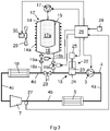
- Fig. 3 shows an embodiment according to the invention.
- the second connection line 18b has also been provided with a second valve member 19b.
- the compensation tank 12 has an alternative design.
- the first volume compensation unit 12 comprises a rigid tank 14 enclosing a flexible body 15, which may be a rubber bladder.
- the space between the flexible body 15 and an inner surface of the rigid tank 14 defines a first space 16 of an adjustable volume for accommodation of the working fluid.
- the volume of the first space 16 depends on the pressure in an air space 17a, which is defined by the flexible body 15.
- a schematically indicated air-regulating device 17 is used to regulate the air pressure in the air space 17a.
- an outer surface of the compensation tank 12 has been provided with cooling fins 14a.
- the cooling fins 14a increase the heat transfer surface between the working fluid in the inner space 16 of the compensation tank 12 and ambient air.
- an air fan 29 is arranged to provide a cooling air flow towards an area of the outer surface of the compensation tank including the cooling fins 14a.
- the air fan is driven by an electric motor 30.
- the embodiment shown in Fig. 3 includes the same components as the example in Fig. 2 .
- the control unit 26 determines a desired condensation pressure at which the WHR system has an optimal efficiency.
- the control unit 26 receives information about the actual condensation pressure from a not indicated sensor. In case there is a difference between the desired condensation pressure and the actual condensation pressure, the control unit 26 activates the actuator 25 such that it provides a movement of the piston 23 which adjusts the volume of the space 24 in a manner such that this pressure difference is eliminated.
- Fig. 4 shows a flow chart illustrating a method for a shutdown phase of the WHR system.
- a driver 1 turns off the ignition in the vehicle 1 such that the combustion engine 2 is turned off and the exhaust flow through the exhaust line 6 ceases.
- the control unit 26 receives information from the ignition system 28 that the ignition has been turned off which means that a shutdown phase of the WHR system is to be started.
- the start of the shutdown phase is provided at step 42.
- the control unit 29 initiates supply of cool working fluid from the compensation tank 12 to the main circuit 4. This may be performed in different ways.
- the expander 7 In the idle mode the expander 7 is disconnected from the power train of the vehicle 1. Alternatively, the working fluid is directed past the expander 7 via a not indicated bypass line. However, in the idle mode, it is possible for the pump 3 to circulate the working fluid through the main circuit 4 with a relatively low flow resistance and with a relatively low consumption of electrical energy.
- the control unit 26 initiates a movement of the first valve device 19a to an open position and a movement of the intermittent valve member 20 to a closed position during the shutdown phase of the WHR system.
- the control unit 26 initiates a movement of the first valve device 19a and the second valve 19b to an open position and a movement of the intermittent valve member 20 to a closed position during the shutdown phase of the WHR system.
- a positioning of the valve members 19a, 19b, 20 means that the circulating working fluid flow enters the compensation tank 12 via the first connection line 18a and leaves the compensation tank 12 via the second connection line 18b.
- the compensation tank 12 During the start-up phase of the WHR system, a relatively large quantity of working fluid is accumulated in the compensation tank 12.
- the accumulated working fluid in the compensation tank 12 is substantially isolated from the working fluid circulating in the main circuit 4.
- the accumulated working fluid in the compensation tank 12 is cooled by ambient air and the working fluid in the main circuit is heated by exhaust gases. Due to these facts, the working fluid in the compensation tank 12 usually has a considerably lower temperature than the working fluid in the main circuit 4.
- the working fluid leaving the compensation tank 12 via the second connection line 18b during the shutdown phase of the WHR system has usually a significantly lower temperature than the working fluid entering the compensation tank 12 via the first connection line 18a.
- hot working fluid is replaced by cool working fluid in the main circuit 4 during the shutdown phase of the WHR system.
- the pressure in the compensation tank 12 can be varied by means of the air regulating device 17 and the pressure in the main circuit 4 can be varied by the pressure member 13.
- the air regulating device 17 increases the pressure in the compensation tank 12 to a higher level than the pressure in the main circuit 4.
- the pressure member 13 can decrease the pressure in the main circuit 4 in order to further increase the pressure difference between the compensation tank 12 and the main circuit 4. Such a pressure difference results in a cool working fluid flow from the compensation tank 12 to the main circuit 4.
- the control unit 26 opens the first valve member 19a and closes the second valve member 19b.
- the intermittent valve member 20 is maintained in the closed position.
- the air regulating device 17 decreases the pressure in the compensation tank 12 to a lower level than the pressure in the main circuit 4.
- the pressure member 13 increase the pressure in the main circuit 4. This pressure difference results in a hot working fluid flow from the main circuit 4 to the compensation tank 12 via the first connection line 18a. Also in this case, it is possible to replace hot working fluid in the main circuit 4 with cool working fluid from the compensation tank 12.
- the control unit 26 receives information from the sensor about the pressure and the temperature of the working fluid in said position adjacent to the expander. In view of this information, the control unit 26 determines if the working fluid is in liquid or gaseous state in this position of the main circuit 4. During the regular operating phase, the working fluid is in gaseous state and it has its highest temperature in the second part 4b of the main circuit 4. During a following shutdown phase of the WHR system, it is a risk that isolated spaces with gaseous working fluid are created adjacent to the expander 7. In case the control unit 26 determines that the working fluid is in liquid state in this position of the main circuit 4, it is very likely that all working fluid in the main circuit 4 is in liquid state. When the control unit 26 receives information from said sensor 27 indicating that all working fluid in the main circuit 4 is in liquid state, it ends the supply of cool working fluid from the compensation tank 12 to the main circuit 4.
- control unit 26 may activate the pressure member 12, at step 45, such that it increases the pressure in the main circuit 4 in order to ensure that a further cooling of the working fluid in the main circuit do not results in a pressure drop to a lower pressure than ambient air pressure.
- the shutdown phase of the WHR system ends at step 46. In view of said active cooling of the working fluid in the main circuit 4, it is possible to perform a very fast shutdown phase of the WHR system.
Landscapes
- Engineering & Computer Science (AREA)
- Chemical & Material Sciences (AREA)
- Combustion & Propulsion (AREA)
- Mechanical Engineering (AREA)
- General Engineering & Computer Science (AREA)
- Physics & Mathematics (AREA)
- Thermal Sciences (AREA)
- Engine Equipment That Uses Special Cycles (AREA)
Claims (16)
- Agencement pour commander une phase d'arrêt d'un système WHR, dans lequel le système WHR comprend un circuit principal (4) qui comprend une pompe (3), un évaporateur (5), un détendeur (7) et un condenseur (10), et un réservoir de compensation (12) qui est configuré pour compenser les changements de volume d'un fluide de travail dans le circuit principal (4) pendant le fonctionnement du système WHR, dans lequel l'agencement comprend une unité de commande (26) configurée pour recevoir des informations lorsque la phase d'arrêt du système WHR doit être initiée et un moyen d'écoulement capable de fournir du fluide de travail depuis le réservoir de compensation (12) au circuit principal (4), et que l'unité de commande (26) est configurée pour activer lesdits moyens d'écoulement de telle sorte que le fluide de travail est fourni depuis le réservoir de compensation (12) au circuit principal (4) lorsqu'il reçoit des informations indiquant que la phase d'arrêt du système WHR doit être initiée, dans lequel ledit moyen d'écoulement comprend un élément d'écoulement (3) agencé pour faire circuler le fluide de travail dans le circuit principal pendant au moins une partie de la phase d'arrêt, et dans lequel l'élément d'écoulement (3) est la pompe (3) dans le système WHR, caractérisé en ce que ledit moyen d'écoulement comprend une première ligne de connexion (18a) et une seconde ligne de connexion (18b) reliant le réservoir de compensation (12) et le circuit principal, un premier élément de vanne (19a) configuré pour diriger le fluide de travail du circuit principal (4) vers le réservoir de compensation (12) via la première ligne de connexion (18a) et un second élément de soupape (19b) configuré pour diriger le fluide de travail du réservoir de compensation (12) vers le circuit principal (4) via la seconde ligne de connexion (18b).
- Agencement selon la revendication 1, dans lequel ledit moyen d'écoulement comprend un élément de pression (17a, 22) configuré pour fournir une différence de pression entre le fluide de travail dans le réservoir de compensation (12) et le fluide de travail dans le circuit principal (4) pendant l'au moins une partie de la phase d'arrêt.
- Agencement selon la revendication 2, dans lequel ledit élément de pression (17a) est agencé pour changer la pression dans le réservoir de compensation (12).
- Agencement selon la revendication 2, dans lequel ledit élément de pression est agencé pour changer la pression dans le circuit principal (4).
- Agencement selon l'une quelconque des revendications précédentes, dans lequel l'unité de commande (26) est configurée pour recevoir des informations indiquant quand tout le fluide de travail dans le circuit principal (4) est à l'état liquide.
- Agencement selon la revendication 5, dans lequel l'unité de commande (26) est configurée pour recevoir des informations sur la température et la pression du fluide de travail dans une position adjacente au détendeur (7).
- Agencement selon l'une quelconque des revendications précédentes, dans lequel l'agencement comprend des moyens de refroidissement (14a, 29) agencés pour refroidir le liquide de travail dans le réservoir de compensation (12).
- Agencement selon la revendication 7, dans lequel ledit moyen de refroidissement comprend des ailettes de refroidissement (14a) agencées sur une surface extérieure du réservoir de compensation.
- Procédé de commande d'une phase d'arrêt d'un système WHR, dans lequel le système WHR comprend un circuit principal (4) qui comprend une pompe (3), un évaporateur (5), un détendeur (7) et un condenseur (10), et un réservoir de compensation (12) qui est configuré pour compenser les changements de volume d'un fluide de travail dans le circuit principal (4) pendant le fonctionnement du système WHR, le procédé étant caractérisé par les étapes suivantes :recevoir des informations lorsque la phase d'arrêt du système WHR doit être initiée, pour fournir du fluide de travail depuis le réservoir de compensation (12) au circuit principal (4) lorsqu'il reçoit des informations indiquant que la phase d'arrêt du système WHR doit être initiée,faire circuler le fluide de travail à travers le circuit principal (4) par un élément d'écoulement (3) pendant au moins une partie de la phase d'arrêt, dans lequel l'élément d'écoulement (3) est la pompe (3) dans le système WHR, etfournir du fluide de travail du circuit principal (4) au réservoir de compensation via une première ligne de connexion (18a) et du réservoir de compensation (12) au circuit principal (4) via une seconde ligne de connexion (18b).
- Procédé selon la revendication 9, comprenant en outre l'étape consistant à créer une différence de pression entre le fluide de travail dans le réservoir de compensation (12) et le fluide de travail dans le circuit principal (4) pendant l'au moins une partie de la phase d'arrêt.
- Procédé selon la revendication 10, comprenant en outre l'étape consistant à modifier la pression dans le réservoir de compensation (12) .
- Procédé selon la revendication 10, comprenant en outre l'étape consistant à modifier la pression dans le circuit principal (4).
- Procédé selon l'une quelconque des revendications précédentes 9 à 12, comprenant en outre l'étape consistant à recevoir des informations indiquant quand tout le fluide de travail dans le circuit principal (4) est à l'état liquide.
- Procédé selon la revendication 13, comprenant en outre l'étape consistant à recevoir des informations sur la température et la pression du fluide de travail dans une position adjacente au détendeur (7).
- Procédé selon l'une quelconque des revendications précédentes 9 à 14, comprenant en outre l'étape consistant à refroidir le liquide de travail dans le réservoir de compensation (12).
- Système WHR, comprenant un agencement selon l'une quelconque des revendications précédentes 1 à 8.
Applications Claiming Priority (2)
| Application Number | Priority Date | Filing Date | Title |
|---|---|---|---|
| SE1850301A SE542807C2 (en) | 2018-03-19 | 2018-03-19 | An arrangement and a method for controlling a shutdown phase of a WHR-system |
| PCT/SE2019/050242 WO2019182498A1 (fr) | 2018-03-19 | 2019-03-19 | Agencement et procédé de commande d'une phase d'arret d'un système whr |
Publications (3)
| Publication Number | Publication Date |
|---|---|
| EP3768953A1 EP3768953A1 (fr) | 2021-01-27 |
| EP3768953A4 EP3768953A4 (fr) | 2021-12-29 |
| EP3768953B1 true EP3768953B1 (fr) | 2023-01-04 |
Family
ID=67987497
Family Applications (1)
| Application Number | Title | Priority Date | Filing Date |
|---|---|---|---|
| EP19770940.5A Active EP3768953B1 (fr) | 2018-03-19 | 2019-03-19 | Agencement et procédé de commande d'une phase d'arret d'un système whr |
Country Status (6)
| Country | Link |
|---|---|
| US (1) | US20210003040A1 (fr) |
| EP (1) | EP3768953B1 (fr) |
| CN (1) | CN111819343A (fr) |
| BR (1) | BR112020017662A2 (fr) |
| SE (1) | SE542807C2 (fr) |
| WO (1) | WO2019182498A1 (fr) |
Families Citing this family (3)
| Publication number | Priority date | Publication date | Assignee | Title |
|---|---|---|---|---|
| EP3879082B1 (fr) * | 2020-03-12 | 2024-07-10 | Volvo Car Corporation | Système de régulation de pression de réservoir pour un système de récupération de chaleur perdue |
| CN113339893A (zh) * | 2021-06-01 | 2021-09-03 | 青岛海信日立空调系统有限公司 | 分流器、换热器及空调机 |
| DE102021213042A1 (de) | 2021-11-19 | 2023-05-25 | Mahle International Gmbh | Verfahren zum Betrieben einer Abwärmenutzungseinrichtung in einem Kraftfahrzeug |
Family Cites Families (8)
| Publication number | Priority date | Publication date | Assignee | Title |
|---|---|---|---|---|
| JP5163620B2 (ja) * | 2009-10-15 | 2013-03-13 | 株式会社豊田自動織機 | 廃熱回生システム |
| SE535680C2 (sv) * | 2011-03-17 | 2012-11-06 | Scania Cv Ab | Arrangemang för att omvandla värmeenergi till mekanisk energi i ett fordon |
| BR112015014528A2 (pt) * | 2012-12-19 | 2017-09-26 | Mack Trucks | aparelho e método de desabilitação de um aparelho de recuperação de calor residual de fluxo de fluido de trabalho. |
| CN106164419A (zh) | 2014-03-14 | 2016-11-23 | 伊顿公司 | Orc系统发动机停闭后压力管理 |
| WO2015197090A1 (fr) | 2014-06-26 | 2015-12-30 | Volvo Truck Corporation | Système de récupération d'énergie thermique |
| EP3161284B1 (fr) * | 2014-06-26 | 2018-09-26 | Volvo Truck Corporation | Système de gaz d'échappement |
| US9863266B2 (en) * | 2015-11-19 | 2018-01-09 | Borgwarner Inc. | Waste heat recovery system for a power source |
| SE539691C2 (en) * | 2016-02-04 | 2017-10-31 | Scania Cv Ab | A method for controlling the temperature of a waste heat recovery system and such a waste heat recovery system |
-
2018
- 2018-03-19 SE SE1850301A patent/SE542807C2/en unknown
-
2019
- 2019-03-19 EP EP19770940.5A patent/EP3768953B1/fr active Active
- 2019-03-19 WO PCT/SE2019/050242 patent/WO2019182498A1/fr unknown
- 2019-03-19 US US16/979,549 patent/US20210003040A1/en not_active Abandoned
- 2019-03-19 BR BR112020017662-1A patent/BR112020017662A2/pt not_active IP Right Cessation
- 2019-03-19 CN CN201980018038.2A patent/CN111819343A/zh active Pending
Also Published As
| Publication number | Publication date |
|---|---|
| SE542807C2 (en) | 2020-07-14 |
| CN111819343A (zh) | 2020-10-23 |
| SE1850301A1 (en) | 2019-09-20 |
| WO2019182498A1 (fr) | 2019-09-26 |
| EP3768953A1 (fr) | 2021-01-27 |
| US20210003040A1 (en) | 2021-01-07 |
| EP3768953A4 (fr) | 2021-12-29 |
| BR112020017662A2 (pt) | 2020-12-22 |
Similar Documents
| Publication | Publication Date | Title |
|---|---|---|
| EP3768953B1 (fr) | Agencement et procédé de commande d'une phase d'arret d'un système whr | |
| US9021807B2 (en) | Waste heat utilization device and operating method | |
| CN102099560B (zh) | 排热再生系统 | |
| EP3227536B1 (fr) | Système de refroidissement pour un système de récupération de chaleur perdue | |
| US20170306806A1 (en) | A cooling arrangement for a whr-system | |
| US12083862B2 (en) | Vehicle-mounted temperature control system | |
| KR20110041392A (ko) | 폐열 회생 시스템 | |
| CN103154442A (zh) | 用于内燃机的废热利用的装置和方法 | |
| EP3532715B1 (fr) | Système de refroidissement pour refroidir un moteur à combustion et système de récupération de chaleur perdue | |
| EP3402964B1 (fr) | Système de refroidissement pour un moteur à combustion et système de récupération de chaleur perdue | |
| US11215101B2 (en) | Arrangement comprising a WHR system and a method for controlling such an arrangement | |
| WO2019117794A1 (fr) | Agencement et procédé de commande d'un système whr | |
| WO2019117788A1 (fr) | Dispositif et procédé de compensation de volume et de regulation de pression d'un milieu de travail dans un système whr | |
| US20140075934A1 (en) | Line circuit and method for operating a line circuit for waste-heat utilization of an internal combustion engine | |
| WO2019147179A1 (fr) | Agencement et procédé de commande d'un système whr | |
| CN114846222A (zh) | 能量回收装置 | |
| EP3594569A1 (fr) | Dispositif de récupération de chaleur | |
| SE541668C2 (en) | A cooling system for a combustion engine and a WHR system | |
| WO2018097780A1 (fr) | Système whr comprenant un condenseur en aluminium | |
| KR20090113152A (ko) | 열교환기를 장착한 열기관 |
Legal Events
| Date | Code | Title | Description |
|---|---|---|---|
| STAA | Information on the status of an ep patent application or granted ep patent |
Free format text: STATUS: THE INTERNATIONAL PUBLICATION HAS BEEN MADE |
|
| PUAI | Public reference made under article 153(3) epc to a published international application that has entered the european phase |
Free format text: ORIGINAL CODE: 0009012 |
|
| STAA | Information on the status of an ep patent application or granted ep patent |
Free format text: STATUS: REQUEST FOR EXAMINATION WAS MADE |
|
| 17P | Request for examination filed |
Effective date: 20201019 |
|
| AK | Designated contracting states |
Kind code of ref document: A1 Designated state(s): AL AT BE BG CH CY CZ DE DK EE ES FI FR GB GR HR HU IE IS IT LI LT LU LV MC MK MT NL NO PL PT RO RS SE SI SK SM TR |
|
| AX | Request for extension of the european patent |
Extension state: BA ME |
|
| RAP3 | Party data changed (applicant data changed or rights of an application transferred) |
Owner name: SCANIA CV AB |
|
| DAV | Request for validation of the european patent (deleted) | ||
| DAX | Request for extension of the european patent (deleted) | ||
| A4 | Supplementary search report drawn up and despatched |
Effective date: 20211129 |
|
| RIC1 | Information provided on ipc code assigned before grant |
Ipc: F25B 41/00 20210101ALI20211123BHEP Ipc: F25B 30/02 20060101ALI20211123BHEP Ipc: F02G 5/02 20060101ALI20211123BHEP Ipc: F01P 11/02 20060101ALI20211123BHEP Ipc: F01N 5/02 20060101ALI20211123BHEP Ipc: F01K 13/02 20060101ALI20211123BHEP Ipc: F01K 23/10 20060101AFI20211123BHEP |
|
| GRAP | Despatch of communication of intention to grant a patent |
Free format text: ORIGINAL CODE: EPIDOSNIGR1 |
|
| STAA | Information on the status of an ep patent application or granted ep patent |
Free format text: STATUS: GRANT OF PATENT IS INTENDED |
|
| INTG | Intention to grant announced |
Effective date: 20220805 |
|
| GRAS | Grant fee paid |
Free format text: ORIGINAL CODE: EPIDOSNIGR3 |
|
| GRAA | (expected) grant |
Free format text: ORIGINAL CODE: 0009210 |
|
| STAA | Information on the status of an ep patent application or granted ep patent |
Free format text: STATUS: THE PATENT HAS BEEN GRANTED |
|
| AK | Designated contracting states |
Kind code of ref document: B1 Designated state(s): AL AT BE BG CH CY CZ DE DK EE ES FI FR GB GR HR HU IE IS IT LI LT LU LV MC MK MT NL NO PL PT RO RS SE SI SK SM TR |
|
| REG | Reference to a national code |
Ref country code: GB Ref legal event code: FG4D |
|
| REG | Reference to a national code |
Ref country code: DE Ref legal event code: R096 Ref document number: 602019024015 Country of ref document: DE |
|
| REG | Reference to a national code |
Ref country code: CH Ref legal event code: EP |
|
| REG | Reference to a national code |
Ref country code: AT Ref legal event code: REF Ref document number: 1542064 Country of ref document: AT Kind code of ref document: T Effective date: 20230115 |
|
| REG | Reference to a national code |
Ref country code: IE Ref legal event code: FG4D |
|
| REG | Reference to a national code |
Ref country code: LT Ref legal event code: MG9D |
|
| REG | Reference to a national code |
Ref country code: NL Ref legal event code: MP Effective date: 20230104 |
|
| REG | Reference to a national code |
Ref country code: AT Ref legal event code: MK05 Ref document number: 1542064 Country of ref document: AT Kind code of ref document: T Effective date: 20230104 |
|
| P01 | Opt-out of the competence of the unified patent court (upc) registered |
Effective date: 20230518 |
|
| PG25 | Lapsed in a contracting state [announced via postgrant information from national office to epo] |
Ref country code: NL Free format text: LAPSE BECAUSE OF FAILURE TO SUBMIT A TRANSLATION OF THE DESCRIPTION OR TO PAY THE FEE WITHIN THE PRESCRIBED TIME-LIMIT Effective date: 20230104 |
|
| PG25 | Lapsed in a contracting state [announced via postgrant information from national office to epo] |
Ref country code: RS Free format text: LAPSE BECAUSE OF FAILURE TO SUBMIT A TRANSLATION OF THE DESCRIPTION OR TO PAY THE FEE WITHIN THE PRESCRIBED TIME-LIMIT Effective date: 20230104 Ref country code: PT Free format text: LAPSE BECAUSE OF FAILURE TO SUBMIT A TRANSLATION OF THE DESCRIPTION OR TO PAY THE FEE WITHIN THE PRESCRIBED TIME-LIMIT Effective date: 20230504 Ref country code: NO Free format text: LAPSE BECAUSE OF FAILURE TO SUBMIT A TRANSLATION OF THE DESCRIPTION OR TO PAY THE FEE WITHIN THE PRESCRIBED TIME-LIMIT Effective date: 20230404 Ref country code: LV Free format text: LAPSE BECAUSE OF FAILURE TO SUBMIT A TRANSLATION OF THE DESCRIPTION OR TO PAY THE FEE WITHIN THE PRESCRIBED TIME-LIMIT Effective date: 20230104 Ref country code: LT Free format text: LAPSE BECAUSE OF FAILURE TO SUBMIT A TRANSLATION OF THE DESCRIPTION OR TO PAY THE FEE WITHIN THE PRESCRIBED TIME-LIMIT Effective date: 20230104 Ref country code: HR Free format text: LAPSE BECAUSE OF FAILURE TO SUBMIT A TRANSLATION OF THE DESCRIPTION OR TO PAY THE FEE WITHIN THE PRESCRIBED TIME-LIMIT Effective date: 20230104 Ref country code: ES Free format text: LAPSE BECAUSE OF FAILURE TO SUBMIT A TRANSLATION OF THE DESCRIPTION OR TO PAY THE FEE WITHIN THE PRESCRIBED TIME-LIMIT Effective date: 20230104 Ref country code: AT Free format text: LAPSE BECAUSE OF FAILURE TO SUBMIT A TRANSLATION OF THE DESCRIPTION OR TO PAY THE FEE WITHIN THE PRESCRIBED TIME-LIMIT Effective date: 20230104 |
|
| PG25 | Lapsed in a contracting state [announced via postgrant information from national office to epo] |
Ref country code: SE Free format text: LAPSE BECAUSE OF FAILURE TO SUBMIT A TRANSLATION OF THE DESCRIPTION OR TO PAY THE FEE WITHIN THE PRESCRIBED TIME-LIMIT Effective date: 20230104 Ref country code: PL Free format text: LAPSE BECAUSE OF FAILURE TO SUBMIT A TRANSLATION OF THE DESCRIPTION OR TO PAY THE FEE WITHIN THE PRESCRIBED TIME-LIMIT Effective date: 20230104 Ref country code: IS Free format text: LAPSE BECAUSE OF FAILURE TO SUBMIT A TRANSLATION OF THE DESCRIPTION OR TO PAY THE FEE WITHIN THE PRESCRIBED TIME-LIMIT Effective date: 20230504 Ref country code: GR Free format text: LAPSE BECAUSE OF FAILURE TO SUBMIT A TRANSLATION OF THE DESCRIPTION OR TO PAY THE FEE WITHIN THE PRESCRIBED TIME-LIMIT Effective date: 20230405 Ref country code: FI Free format text: LAPSE BECAUSE OF FAILURE TO SUBMIT A TRANSLATION OF THE DESCRIPTION OR TO PAY THE FEE WITHIN THE PRESCRIBED TIME-LIMIT Effective date: 20230104 |
|
| REG | Reference to a national code |
Ref country code: DE Ref legal event code: R097 Ref document number: 602019024015 Country of ref document: DE |
|
| PG25 | Lapsed in a contracting state [announced via postgrant information from national office to epo] |
Ref country code: SM Free format text: LAPSE BECAUSE OF FAILURE TO SUBMIT A TRANSLATION OF THE DESCRIPTION OR TO PAY THE FEE WITHIN THE PRESCRIBED TIME-LIMIT Effective date: 20230104 Ref country code: RO Free format text: LAPSE BECAUSE OF FAILURE TO SUBMIT A TRANSLATION OF THE DESCRIPTION OR TO PAY THE FEE WITHIN THE PRESCRIBED TIME-LIMIT Effective date: 20230104 Ref country code: MC Free format text: LAPSE BECAUSE OF FAILURE TO SUBMIT A TRANSLATION OF THE DESCRIPTION OR TO PAY THE FEE WITHIN THE PRESCRIBED TIME-LIMIT Effective date: 20230104 Ref country code: EE Free format text: LAPSE BECAUSE OF FAILURE TO SUBMIT A TRANSLATION OF THE DESCRIPTION OR TO PAY THE FEE WITHIN THE PRESCRIBED TIME-LIMIT Effective date: 20230104 Ref country code: DK Free format text: LAPSE BECAUSE OF FAILURE TO SUBMIT A TRANSLATION OF THE DESCRIPTION OR TO PAY THE FEE WITHIN THE PRESCRIBED TIME-LIMIT Effective date: 20230104 Ref country code: CZ Free format text: LAPSE BECAUSE OF FAILURE TO SUBMIT A TRANSLATION OF THE DESCRIPTION OR TO PAY THE FEE WITHIN THE PRESCRIBED TIME-LIMIT Effective date: 20230104 |
|
| REG | Reference to a national code |
Ref country code: CH Ref legal event code: PL |
|
| PLBE | No opposition filed within time limit |
Free format text: ORIGINAL CODE: 0009261 |
|
| STAA | Information on the status of an ep patent application or granted ep patent |
Free format text: STATUS: NO OPPOSITION FILED WITHIN TIME LIMIT |
|
| PG25 | Lapsed in a contracting state [announced via postgrant information from national office to epo] |
Ref country code: SK Free format text: LAPSE BECAUSE OF FAILURE TO SUBMIT A TRANSLATION OF THE DESCRIPTION OR TO PAY THE FEE WITHIN THE PRESCRIBED TIME-LIMIT Effective date: 20230104 |
|
| REG | Reference to a national code |
Ref country code: BE Ref legal event code: MM Effective date: 20230331 |
|
| 26N | No opposition filed |
Effective date: 20231005 |
|
| GBPC | Gb: european patent ceased through non-payment of renewal fee |
Effective date: 20230404 |
|
| PG25 | Lapsed in a contracting state [announced via postgrant information from national office to epo] |
Ref country code: LU Free format text: LAPSE BECAUSE OF NON-PAYMENT OF DUE FEES Effective date: 20230319 |
|
| REG | Reference to a national code |
Ref country code: IE Ref legal event code: MM4A |
|
| PG25 | Lapsed in a contracting state [announced via postgrant information from national office to epo] |
Ref country code: GB Free format text: LAPSE BECAUSE OF NON-PAYMENT OF DUE FEES Effective date: 20230404 |
|
| PG25 | Lapsed in a contracting state [announced via postgrant information from national office to epo] |
Ref country code: SI Free format text: LAPSE BECAUSE OF FAILURE TO SUBMIT A TRANSLATION OF THE DESCRIPTION OR TO PAY THE FEE WITHIN THE PRESCRIBED TIME-LIMIT Effective date: 20230104 Ref country code: LI Free format text: LAPSE BECAUSE OF NON-PAYMENT OF DUE FEES Effective date: 20230331 Ref country code: IE Free format text: LAPSE BECAUSE OF NON-PAYMENT OF DUE FEES Effective date: 20230319 Ref country code: GB Free format text: LAPSE BECAUSE OF NON-PAYMENT OF DUE FEES Effective date: 20230404 Ref country code: FR Free format text: LAPSE BECAUSE OF NON-PAYMENT OF DUE FEES Effective date: 20230331 Ref country code: CH Free format text: LAPSE BECAUSE OF NON-PAYMENT OF DUE FEES Effective date: 20230331 |
|
| PG25 | Lapsed in a contracting state [announced via postgrant information from national office to epo] |
Ref country code: BE Free format text: LAPSE BECAUSE OF NON-PAYMENT OF DUE FEES Effective date: 20230331 |
|
| PGFP | Annual fee paid to national office [announced via postgrant information from national office to epo] |
Ref country code: DE Payment date: 20240130 Year of fee payment: 6 |
|
| PG25 | Lapsed in a contracting state [announced via postgrant information from national office to epo] |
Ref country code: IT Free format text: LAPSE BECAUSE OF FAILURE TO SUBMIT A TRANSLATION OF THE DESCRIPTION OR TO PAY THE FEE WITHIN THE PRESCRIBED TIME-LIMIT Effective date: 20230104 |