EP3768545B1 - Module with a plurality control elements - Google Patents
Module with a plurality control elements Download PDFInfo
- Publication number
- EP3768545B1 EP3768545B1 EP19706954.5A EP19706954A EP3768545B1 EP 3768545 B1 EP3768545 B1 EP 3768545B1 EP 19706954 A EP19706954 A EP 19706954A EP 3768545 B1 EP3768545 B1 EP 3768545B1
- Authority
- EP
- European Patent Office
- Prior art keywords
- operator control
- control elements
- module according
- module
- control element
- Prior art date
- Legal status (The legal status is an assumption and is not a legal conclusion. Google has not performed a legal analysis and makes no representation as to the accuracy of the status listed.)
- Active
Links
- 230000004044 response Effects 0.000 claims description 4
- 230000006870 function Effects 0.000 description 22
- 238000004804 winding Methods 0.000 description 4
- 230000008859 change Effects 0.000 description 3
- 238000009434 installation Methods 0.000 description 3
- 238000003825 pressing Methods 0.000 description 3
- 230000001419 dependent effect Effects 0.000 description 2
- 230000008447 perception Effects 0.000 description 2
- 230000008672 reprogramming Effects 0.000 description 2
- 230000003213 activating effect Effects 0.000 description 1
- 230000003321 amplification Effects 0.000 description 1
- 230000008901 benefit Effects 0.000 description 1
- 230000001427 coherent effect Effects 0.000 description 1
- 230000008602 contraction Effects 0.000 description 1
- 230000000694 effects Effects 0.000 description 1
- 230000003993 interaction Effects 0.000 description 1
- 238000004519 manufacturing process Methods 0.000 description 1
- 238000000034 method Methods 0.000 description 1
- 238000003199 nucleic acid amplification method Methods 0.000 description 1
- 230000008569 process Effects 0.000 description 1
- 238000003860 storage Methods 0.000 description 1
- 238000009423 ventilation Methods 0.000 description 1
Images


Classifications
-
- G—PHYSICS
- G06—COMPUTING; CALCULATING OR COUNTING
- G06F—ELECTRIC DIGITAL DATA PROCESSING
- G06F3/00—Input arrangements for transferring data to be processed into a form capable of being handled by the computer; Output arrangements for transferring data from processing unit to output unit, e.g. interface arrangements
- G06F3/01—Input arrangements or combined input and output arrangements for interaction between user and computer
- G06F3/02—Input arrangements using manually operated switches, e.g. using keyboards or dials
- G06F3/023—Arrangements for converting discrete items of information into a coded form, e.g. arrangements for interpreting keyboard generated codes as alphanumeric codes, operand codes or instruction codes
- G06F3/0238—Programmable keyboards
-
- B60K35/10—
-
- G—PHYSICS
- G06—COMPUTING; CALCULATING OR COUNTING
- G06F—ELECTRIC DIGITAL DATA PROCESSING
- G06F3/00—Input arrangements for transferring data to be processed into a form capable of being handled by the computer; Output arrangements for transferring data from processing unit to output unit, e.g. interface arrangements
- G06F3/01—Input arrangements or combined input and output arrangements for interaction between user and computer
- G06F3/016—Input arrangements with force or tactile feedback as computer generated output to the user
-
- H—ELECTRICITY
- H01—ELECTRIC ELEMENTS
- H01H—ELECTRIC SWITCHES; RELAYS; SELECTORS; EMERGENCY PROTECTIVE DEVICES
- H01H9/00—Details of switching devices, not covered by groups H01H1/00 - H01H7/00
- H01H9/18—Distinguishing marks on switches, e.g. for indicating switch location in the dark; Adaptation of switches to receive distinguishing marks
- H01H9/181—Distinguishing marks on switches, e.g. for indicating switch location in the dark; Adaptation of switches to receive distinguishing marks using a programmable display, e.g. LED or LCD
-
- B60K2360/111—
-
- B60K2360/126—
-
- B60K2360/1442—
-
- H—ELECTRICITY
- H01—ELECTRIC ELEMENTS
- H01H—ELECTRIC SWITCHES; RELAYS; SELECTORS; EMERGENCY PROTECTIVE DEVICES
- H01H3/00—Mechanisms for operating contacts
- H01H2003/008—Mechanisms for operating contacts with a haptic or a tactile feedback controlled by electrical means, e.g. a motor or magnetofriction
-
- H—ELECTRICITY
- H01—ELECTRIC ELEMENTS
- H01H—ELECTRIC SWITCHES; RELAYS; SELECTORS; EMERGENCY PROTECTIVE DEVICES
- H01H3/00—Mechanisms for operating contacts
- H01H3/02—Operating parts, i.e. for operating driving mechanism by a mechanical force external to the switch
- H01H2003/0293—Operating parts, i.e. for operating driving mechanism by a mechanical force external to the switch with an integrated touch switch
-
- H—ELECTRICITY
- H01—ELECTRIC ELEMENTS
- H01H—ELECTRIC SWITCHES; RELAYS; SELECTORS; EMERGENCY PROTECTIVE DEVICES
- H01H2233/00—Key modules
- H01H2233/03—Key modules mounted on support plate or frame
Definitions
- the present invention relates to a module with several control elements for vehicle components.
- control elements In addition to new operating concepts, such as voice or gesture controls, mechanical control elements in the form of control knobs, buttons and switches are still used.
- GB2481597A a programmable display system provided inside a vehicle, such as an emergency vehicle, and allowing user control of systems of the vehicle.
- the device described has mechanical buttons, each of which has an OLED display panel for displaying the function assigned to a button by means of an image or symbol
- the functionality of the buttons and the images or symbols displayed is programmable, so that if the functionality of a button changes, a different image or symbol can be displayed.
- the EN 10 2015 009313 A1 relates to an operating device for a motor vehicle, comprising an operating device; an actuator which has an armature coupled to the operating device and at least two winding units which are designed to generate respective magnetic fields for deflecting the armature mounted so as to be movable relative to the winding units, wherein the winding units differ at least with respect to one property; a control device which is designed to control the winding units depending on a detected actuation of the operating device to generate the respective magnetic fields in order to bring about at least one haptically detectable feedback on the operating device.
- the haptic feedback according to the invention improves the interaction between the vehicle user and the vehicle. Feedback can be given to the vehicle user even if the electronic display unit is not visible, for example because it is covered by the vehicle user's finger. In fact, the feedback can be given without changing the display assigned to the control element. If the operating unit is operated by the driver of the vehicle, this reduces driver distraction and thus increases driving safety, as the driver does not have to take his eyes off the road due to the perception of the haptic feedback.
- the operating element in response to an actuation of the actuating unit, is reprogrammed such that a second display different from the first display is shown on the electronic display unit and/or a second haptic feedback different from the first haptic feedback is generated.
- the electronic display unit is designed as an OLED, MicroLED or LCD display.
- an image symbol is shown on the electronic display unit which represents a function assigned to the control element.
- the actuator for generating haptic feedback is advantageously designed as a piezo actuator, vibration motor or another mechanically deformable element.
- the actuation unit has a force sensor or proximity sensor for detecting the actuation by the vehicle user.
- the electronic display unit is designed as a touch-sensitive screen, wherein the vehicle user operates it by touching the touch-sensitive screen.
- the operating unit is designed as a mechanical push button.
- the invention also relates to a module for a vehicle with multiple control elements.
- a module for a vehicle with multiple control elements.
- Such a module has the advantage, among other things, that multiple control elements can be installed together or simultaneously in one step, which simplifies assembly and reduces assembly time.
- the individual control elements each have a separate control element housing, wherein the control element housings are arranged separately from one another in a common module housing.
- FIG 1 shows an embodiment of an operating element 1 according to the invention.
- an electronic display unit On the front of the operating element 1 an electronic display unit is arranged, as in the Figure 1a
- the electronic display unit can be designed as a MicroLED, OLED or LCD display, but other display types that have a small installation depth are also suitable.
- the electronic display unit preferably enables an RGB color display, but a monochrome display is also conceivable.
- the display also has a sufficient number of pixels, e.g. 64 x 64 or 96 x 64 pixels, to be able to display different symbols clearly.
- the display on the electronic display unit can be freely programmed to display different symbols simultaneously on several control elements or one after the other on the same control element.
- the individual components of the control element 1 are arranged in a housing 3 that has guides 4 on the outside for play-free fastening in a module housing described below. However, other fastening elements can also be provided for fixing the control element 1.
- FIG. 1b shows a rear view of the control element according to the invention.
- a piezo actuator 5 is provided as an actuator for generating haptic feedback, whereby the design of the haptic feedback, for example with regard to strength, duration and frequency, can also be freely programmable.
- the piezo actuator 5 can consist of several piezo plates in order to be able to operate with relatively low operating voltages and to increase the expansion when the operating voltage is applied. In addition, the expansion or contraction can be further increased by a lever effect.
- a sensor function for detecting the operation by the user can also be integrated into the piezo actuator 5.
- Electrical contacts 6 are provided for the electrical contacting of the control element.
- pins 7 in the corners of the back ensure further centering and guidance in the module housing.
- control element thus makes it possible to select the symbol or image displayed, as well as its color design and brightness, according to the vehicle model, the selected menu and/or the state of the selection.
- haptic feedback or tactile perception for the user can also be dependent on the function of the respective control element, for example.
- the display and/or haptic feedback can be adapted by reprogramming in response to an actuation of an actuation unit of the control element.
- control element has an actuation unit which, when the control element is actuated by the user, generates an electrical control signal for the vehicle component or function being operated, which can then be fed to a control unit for further processing.
- the operating unit can be designed as a mechanical push button or push switch, but a design in the form of other mechanical switches is also possible.
- the electronic display unit can also be designed as a touch-sensitive screen, so-called touchscreen, and the vehicle user can operate it by touching the touch-sensitive screen.
- the Actuation by the vehicle user can also be detected, for example, by an integrated force sensor or proximity sensor.
- various forms of operation are possible. For example, when using a force sensor, it is possible to emulate double clicks by pressing the push button harder and to confirm a detected actuation by means of a vibration. It can also be provided that the actuator is only activated when the vehicle user detects that the actuation unit has been actuated.
- control element according to the invention can be installed individually in the vehicle.
- several control elements can be combined and then, if necessary, represent a coherent user interface depending on the selected menu and/or the current situation.
- the individual control elements are nevertheless physically separate, with each control element only having one function. This makes operation easier for the vehicle user, as he presses a single push button as usual to carry out a specific function, so that this is also possible without looking at the respective push button.
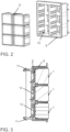
- a module 8 of six control elements in a 2 x 3 arrangement with associated module housing 9 is in Figure 2 shown.
- Each of the control elements can be programmed and controlled separately.
- the control elements can therefore be arranged in any number and in any order.
- a matrix-shaped arrangement with one or more control elements next to each other and one or more control elements on top of each other is often useful, but instead of such a rectangular arrangement, a different arrangement may also be useful depending on the installation location in the vehicle.
- the number of control elements also depends on the space available at the installation location and must also be coordinated with the performance of the control unit.
- the individual control elements of the module are arranged in a module housing 9, which has rails 10 that interact with the guides on the outside of the control element housing so that they are attached without play.
- the module housing also has holes on the back for cables, plugs or connection terminals.
- the module housing 9 on the module housing 9 on the outside fastening elements 11 such as locking elements, which can snap into corresponding recesses in the vehicle interior paneling, are provided.
- a lever-shaped design 12 behind the respective piezo actuator 5 enables an amplification of the haptic feedback generated by the piezo actuator.
- a force sensor 13 is provided which detects the pressure exerted by the vehicle user on the respective control element.
- FIG. 4 shows schematically how such a module can be installed in the interior of a vehicle, preferably in an area that is easily accessible to the vehicle user, such as in the area of the center console. Behind the module, a control unit 14 is indicated, which controls the individual control elements of the module.
- FIG. 5 A first application example for a module with six control elements in a 2 x 3 arrangement is shown in Figure 5 shown schematically. A different symbol is shown on each of the control elements in the left-hand menu.
- the clock can be set by operating the control element 15, on which a clock symbol is shown. If such an operation is carried out by the vehicle user, the representations on the control elements change and different symbols are now displayed, which reflect functions for setting the clock function.
- the time is increased.
- the piezo actuator of the control element 16 gives the vehicle user a haptic feedback that gradually becomes stronger.
- the time can also be reset by pressing the control element 17, which has a "-" symbol, whereby the haptic feedback to the vehicle user gradually becomes weaker.
- the setting process can then be completed by pressing the control element 18.
- the piezo actuator of the control element 18 can make this button vibrate. Since the functions for setting the clock function are no longer required, the symbols originally shown are then displayed on the control elements again.
- FIG. 6 Another application example is in Figure 6 shown.
- a different symbol is shown on each of the control elements in the form of a menu, in this case relating to the light, windscreen wiper and ventilation settings.
- the function of the control elements and representations on the control elements are changed in the event of an accident.
- the vehicle accident can be detected, for example, by the deployment of an airbag.
- corresponding representations such as Warning signs or SOS text are shown on the displays of all control elements so that the vehicle user can use any of these controls to trigger an emergency mode and, for example, make an emergency call via a mobile phone connection.
- the vehicle user has better and faster access to these controls compared to a conventional emergency or SOS button, which may be difficult to reach and, because they are used very rarely, are not immediately found in an accident situation.
- the various functionalities, representations and forms of haptic feedback of the controls can be programmed at the factory before the vehicle is delivered. However, it is also possible to load new functions for the controls into the vehicle using a software update, for example via a mobile network. It is also possible to provide functions that are only available at certain geographical positions of the vehicle, for example to only allow the vehicle's trunk to be opened at home.
Description
Die vorliegende Erfindung betrifft ein Modul mit mehrere Bedienelementen für Fahrzeugkomponente.The present invention relates to a module with several control elements for vehicle components.
Die steigende Anzahl unterschiedlicher Funktionen und Komponenten im Fahrzeug sowie deren immer weiter zunehmende Komplexität hat zu einer Vielzahl von Bedienelementen geführt. Neben neuen Bedienkonzepten, wie beispielsweise Sprach- oder Gestensteuerungen, kommen weiterhin mechanische Bedienelemente in Form von Bedienknöpfen, Tasten und Schalter zum Einsatz.The increasing number of different functions and components in the vehicle and their ever-increasing complexity has led to a large number of control elements. In addition to new operating concepts, such as voice or gesture controls, mechanical control elements in the form of control knobs, buttons and switches are still used.
Die Vielzahl unterschiedlicher Beschriftungen für unterschiedliche Fahrzeugfunktionen und - komponenten sowie die unterschiedlichen Designs der verschiedenen Fahrzeughersteller und -modelle resultiert hierbei, selbst bei gleichem mechanischen Design und Abmessungen, zu einer große Anzahl von Varianten dieser mechanischen Bedienelemente, was u.a. zusätzlichen Aufwand bei der Produktion und Lagerhaltung verursacht. Weiterhin nimmt, zumindest bei einer Bedienung der Vielzahl an Fahrzeugfunktionen und - komponenten ausschließlich oder überwiegend durch mechanische Bedienelemente, deren Anzahl weiterhin zu. Dieses ist neben der Funktionsvielfalt insbesondere auch der Fall, weil zur Sicherstellung von Bedienkomfort und Bediensicherheit eine Taste typischerweise nur eine, nämlich die auf ihr wiedergegebene, Funktion hat und ein Teil der Tasten nur unter bestimmten Bedingungen anwendbar ist, wie beispielsweise das Ein- / Ausschalten eines Tempomaten nur während der Fahrt oder das Ein- / Ausschalten der Handbremse nur bei Stillstand des Fahrzeugs. Ebenso kann eine Verwendung einer Vielzahl mechanischer Bedienelemente störend beim Design des Fahrzeuginteriors sein bzw. dieses verkomplizieren.The large number of different labels for different vehicle functions and components as well as the different designs of the various vehicle manufacturers and models results in a large number of variants of these mechanical controls, even with the same mechanical design and dimensions, which causes additional costs in production and storage, among other things. Furthermore, at least when the large number of vehicle functions and components are operated exclusively or predominantly by mechanical controls, the number of these continues to increase. In addition to the variety of functions, this is particularly the case because, in order to ensure ease of use and operating safety, a button typically only has one function, namely the one shown on it, and some of the buttons can only be used under certain conditions, such as switching a cruise control on/off only when driving or switching the handbrake on/off only when the vehicle is stationary. Likewise, the use of a large number of mechanical controls can disrupt the design of the vehicle interior or complicate it.
Um die Anzahl mechanischer Bedienelemente zu reduzieren, können diese so ausgestaltet sein, dass ihnen durch eine Umprogrammierung mehrere unterschiedliche Funktionen zugewiesen werden können. So offenbart die
Die
Es ist eine Aufgabe der Erfindung, ein Modul für ein Fahrzeug mit demgegenüber verbessertem Bedienkomfort bzw. verbesserter Bediensicherheit, sowie ein Modul mit mehreren solchen Bedienelementen zur Verfügung zu stellen.It is an object of the invention to provide a module for a vehicle with improved operating comfort or improved operating safety, as well as a module with several such operating elements.
Diese Aufgabe wird durch ein Modul mit den Merkmalen des Anspruchs 1 gelöst. Bevorzugte Ausgestaltungen der Erfindung sind Gegenstand der abhängigen Ansprüche.This object is achieved by a module having the features of
Durch die erfindungsgemässe haptische Rückmeldung wird die Interaktion zwischen Fahrzeugnutzer und Fahrzeug verbessert. So kann eine Rückmeldung an den Fahrzeugnutzer selbst dann gegeben werden, wenn die elektronische Anzeigeeinheit nicht einsehbar ist, beispielsweise weil sie durch einen Finger des Fahrzeugnutzers verdeckt wird. Vielmehr kann die Rückmeldung ohne eine Veränderung der dem Bedienelement zugeordneten Anzeige erfolgen. Wird die Betätigungseinheit durch den Fahrer des Fahrzeugs betätigt, senkt dieses die Fahrerablenkung und erhöht damit die Fahrsicherheit, da der Fahrer wegen der Wahrnehmung der haptische Rückmeldung seinen Blick nicht von der Straße nehmen muss.The haptic feedback according to the invention improves the interaction between the vehicle user and the vehicle. Feedback can be given to the vehicle user even if the electronic display unit is not visible, for example because it is covered by the vehicle user's finger. In fact, the feedback can be given without changing the display assigned to the control element. If the operating unit is operated by the driver of the vehicle, this reduces driver distraction and thus increases driving safety, as the driver does not have to take his eyes off the road due to the perception of the haptic feedback.
Vorzugsweise wird hierbei in Reaktion auf eine Betätigung der Betätigungseinheit das Bedienelement derart umprogrammiert, dass eine von der ersten Anzeige verschiedene zweite Anzeige auf der elektronischen Anzeigeeinheit dargestellt und/oder eine von der ersten haptischen Rückmeldung verschiedene zweite haptische Rückmeldung erzeugt wird.Preferably, in response to an actuation of the actuating unit, the operating element is reprogrammed such that a second display different from the first display is shown on the electronic display unit and/or a second haptic feedback different from the first haptic feedback is generated.
Gemäß einer Ausführungsform der Erfindung ist die elektronische Anzeigeeinheit als OLED-, MicroLED oder LCD-Display ausgestaltet.According to one embodiment of the invention, the electronic display unit is designed as an OLED, MicroLED or LCD display.
Vorzugsweise wird auf der elektronischen Anzeigeeinheit ein Bildsymbol dargestellt, das eine dem Bedienelement zugeordnete Funktion wiedergibt.Preferably, an image symbol is shown on the electronic display unit which represents a function assigned to the control element.
Weiterhin ist vorteilhafterweise das Stellglied zur Erzeugung einer haptischen Rückmeldung als Piezoaktuator, Vibrationsmotor oder ein anderes mechanisch verformbares Element ausgestaltet.Furthermore, the actuator for generating haptic feedback is advantageously designed as a piezo actuator, vibration motor or another mechanically deformable element.
Gemäß einer Ausführungsform der Erfindung weist die Betätigungseinheit einen Kraftsensor oder Annäherungssensor zur Erfassung der Betätigung durch den Fahrzeugnutzer auf.According to one embodiment of the invention, the actuation unit has a force sensor or proximity sensor for detecting the actuation by the vehicle user.
Gemäß einer weiteren Ausführungsform der Erfindung ist die elektronische Anzeigeeinheit als berührungsempfindlicher Bildschirm ausgestaltet, wobei die Betätigung durch den Fahrzeugnutzer mittels einer Berührung des berührungsempfindlichen Bildschirms erfolgt. Gemäß einer nochmals weiteren Ausführungsform der Erfindung ist die Betätigungseinheit als mechanischer Druckknopf ausgestaltet ist.According to a further embodiment of the invention, the electronic display unit is designed as a touch-sensitive screen, wherein the vehicle user operates it by touching the touch-sensitive screen. According to yet another embodiment of the invention, the operating unit is designed as a mechanical push button.
Weiterhin betrifft die Erfindung auch ein Modul für ein Fahrzeug mit mehreren Bedienelementen. Ein solches Modul hat unter anderem den Vorteil, dass mehrere Bedienelemente in einem Arbeitsschritt gemeinsam bzw. gleichzeitig eingebaut werden können, was die Montage vereinfacht und die Montagezeit verringert.The invention also relates to a module for a vehicle with multiple control elements. Such a module has the advantage, among other things, that multiple control elements can be installed together or simultaneously in one step, which simplifies assembly and reduces assembly time.
Vorteilhafterweise weisen die einzelnen Bedienelemente jeweils ein separates Bedienelementgehäuse auf, wobei die Bedienelementgehäuse voneinander separiert in einem gemeinsamen Modulgehäuse angeordnet sind.Advantageously, the individual control elements each have a separate control element housing, wherein the control element housings are arranged separately from one another in a common module housing.
Schließlich ist vorteilhafterweise eine Steuereinheit vorgesehen mittels der die mehreren Bedienelemente separat angesteuert werden können und welches das elektrische Steuersignal erzeugt.
- Fig. 1
- zeigt eine Frontansicht (a) und Rückansicht (b) eines erfindungsgemäßen Bedienelements;
- Fig. 2
- zeigt ein erfindungsgemäßes Modul am Beispiel von sechs Bedienelementen in einer 2 x 3 Anordnung mit zugehörigem Modulgehäuse;
- Fig. 3
- zeigt schematisch einen seitlichen Querschnitt durch Modul aus
Figur 2 - Fig. 4
- zeigt schematisch das im Innenraum eines Fahrzeugs verbautes Modul aus
Figur 2 - Fig. 5
- zeigt schematisch für ein erstes Anwendungsbeispiel die Veränderung der unterschiedlichen Anzeigen auf den elektronischen Anzeigeeinheiten der Bedienelemente; und
- Fig. 6
- zeigt schematisch für ein zweites Anwendungsbeispiel die Veränderung der unterschiedlichen Anzeigen auf den elektronischen Anzeigeeinheiten der Bedienelemente.
- Fig.1
- shows a front view (a) and rear view (b) of an operating element according to the invention;
- Fig.2
- shows a module according to the invention using the example of six control elements in a 2 x 3 arrangement with associated module housing;
- Fig.3
- shows schematically a lateral cross-section through module made of
Figure 2 ; - Fig.4
- shows schematically the module installed in the interior of a vehicle
Figure 2 ; - Fig.5
- shows schematically for a first application example the change of the different displays on the electronic display units of the control elements; and
- Fig.6
- shows schematically for a second application example the change of the different displays on the electronic display units of the control elements.
Zum besseren Verständnis der Prinzipien der vorliegenden Erfindung werden nachfolgend Ausführungsformen der Erfindung anhand der Figuren detaillierter erläutert.To better understand the principles of the present invention, embodiments of the invention are explained in more detail below with reference to the figures.
Das erfindungsgemäße Bedienelement ermöglicht damit einerseits das dargestellte Symbol bzw. Bild, aber auch dessen Farbgestaltung und Helligkeit entsprechend dem Fahrzeugmodell, dem ausgewählten Menü und/oder dem Zustand der Auswahl zu wählen. Ebenso kann auch die haptische Rückmeldung bzw. die taktile Wahrnehmung für den Nutzer beispielsweise abhängig von der Funktion des jeweiligen Bedienelements erfolgen. Insbesondere kann hierbei in Reaktion auf eine Betätigung einer Betätigungseinheit des Bedienelements die Anzeige und/oder haptische Rückmeldung durch eine Umprogrammierung angepasst werden.The control element according to the invention thus makes it possible to select the symbol or image displayed, as well as its color design and brightness, according to the vehicle model, the selected menu and/or the state of the selection. Likewise, the haptic feedback or tactile perception for the user can also be dependent on the function of the respective control element, for example. In particular, the display and/or haptic feedback can be adapted by reprogramming in response to an actuation of an actuation unit of the control element.
Ferner weist das Bedienelement eine Betätigungseinheit auf, die bei Betätigung des Bedienelements durch den Nutzer zum Erzeugen eines elektrischen Steuersignals für die bediente Fahrzeugkomponente bzw. -funktion führt, das dann zur weiteren Verarbeitung zunächst einer Steuereinheit zugeführt werden kann.Furthermore, the control element has an actuation unit which, when the control element is actuated by the user, generates an electrical control signal for the vehicle component or function being operated, which can then be fed to a control unit for further processing.
In der in
Das erfindungsgemäße Bedienelement kann einzeln im Fahrzeug verbaut werden. Insbesondere können aber mehrere Bedienelemente zusammengefasst werden und dann ggfs. auch abhängig vom ausgewählten Menü und / oder der aktuellen Situation eine zusammengehörende Benutzeroberfläche darstellen. Hierbei sind die einzelnen Bedienelemente dennoch physisch getrennt, wobei jedes Bedienelement jeweils nur eine Funktion trägt. Dieses erleichtert dem Fahrzeugnutzer die Bedienung, da er wie gewohnt einen einzelnen Druckknopf zum Ausführen einer bestimmten Funktion drückt, so dass dieses ggfs. auch möglich ist ohne den jeweiligen Druckknopf zu betrachten.The control element according to the invention can be installed individually in the vehicle. In particular, however, several control elements can be combined and then, if necessary, represent a coherent user interface depending on the selected menu and/or the current situation. The individual control elements are nevertheless physically separate, with each control element only having one function. This makes operation easier for the vehicle user, as he presses a single push button as usual to carry out a specific function, so that this is also possible without looking at the respective push button.
Ein Modul 8 von sechs Bedienelementen in einer 2 x 3 Anordnung mit zugehörigem Modulgehäuse 9 ist in
Die einzelnen Bedienelemente des Moduls werden in einem Modulgehäuse 9 angeordnet, das Schienen 10 aufweist, die so auf die an der Außenseite der Bedienelementgehäuse befindlichen Führungen zusammenwirken, dass eine spielfreie Befestigung erfolgt. Weiterhin weist das Modulgehäuse an der Rückseite Bohrungen für Kabel, Stecker oder Anschlussklemmen auf.The individual control elements of the module are arranged in a
Ferner sind, wie in dem in
Ein erstes Anwendungsbeispiel für ein Modul mit sechs Bedienelementen in einer 2 x 3 Anordnung ist in
Drückt der den Fahrzeugnutzer nun das Bedienelement 16, welches ein "+"-Symbol anzeigt, so wird die Uhrzeit erhöht. Gleichzeitig wird durch den Piezoaktuator des Bedienelements 16 eine haptische Rückmeldung an den Fahrzeugnutzer ausgegeben die allmählich stärker wird. Ebenso kann die Uhrzeit zurückgestellt werden indem das Bedienelement 17, welches ein "-"-Symbol trägt, gedrückt wird, wobei dann die haptische Rückmeldung an den Fahrzeugnutzer allmählich schwächer wird. Der Einstellvorgang kann dann durch Drücken des Bedienelements 18 abgeschlossen werden. Zur Bestätigung kann durch den Piezoaktuator des Bedienelements 18 diese Taste zum Vibrieren gebracht werden. Da nun die Funktionen zur Einstellung der Uhrfunktion nicht weiter benötigt werden, werden im Anschluss darauf auf den Bedienelementen wieder die ursprünglich dargestellten Symbole angezeigt.If the vehicle user now presses the
Ein weiteres Anwendungsbeispiel ist in
Die verschiedenen Funktionalitäten, Darstellungen und Formen der haptischen Rückkopplung der Bedienelemente kann werkseitig bereits vor Auslieferung des Fahrzeugs programmiert werden. Es ist aber auch möglich, neue Funktionen für die Bedienelemente mittels eines Software-Updates beispielsweise über ein Mobilfunknetz in das Fahrzeug zu laden. Ebenso kann vorgesehen werden, Funktionen vorzusehen, die nur bei bestimmten geografischen Positionen des Fahrzeugs verfügbar sind, beispielsweise um das Öffnen des Kofferraums des Fahrzeugs nur zu Hause zu ermöglichen.The various functionalities, representations and forms of haptic feedback of the controls can be programmed at the factory before the vehicle is delivered. However, it is also possible to load new functions for the controls into the vehicle using a software update, for example via a mobile network. It is also possible to provide functions that are only available at certain geographical positions of the vehicle, for example to only allow the vehicle's trunk to be opened at home.
- 11
- Bedienelement für eine FahrzeugkomponenteControl element for a vehicle component
- 22
- elektronische Anzeigeeinheitelectronic display unit
- 33
- BedienelementgehäuseControl element housing
- 44
- Führungen am BedienelementgehäuseGuides on the control element housing
- 55
- StellgliedActuator
- 66
- elektrische Kontakteelectrical contacts
- 77
- Stiftepencils
- 88th
- Modul mit sechs Bedienelementen in einer 2 x 3 AnordnungModule with six control elements in a 2 x 3 arrangement
- 99
- ModulgehäuseModule housing
- 1010
- Führungen am ModulgehäuseGuides on the module housing
- 1111
- BefestigungselementeFasteners
- 1212
- Hebellever
- 1313
- KraftsensorForce sensor
- 1414
- SteuereinheitControl unit
- 1515
- Bedienelement zur Anwahl der UhrfunktionenControl element for selecting the clock functions
- 16 - 1816 - 18
- Bedienelemente zur Einstellung von UhrfunktionenControls for setting clock functions
Claims (10)
- Module for a vehicle, wherein a plurality of individual operator control elements are combined in the module and are arranged in a common module housing (9), wherein the individual operator control elements each comprise an actuating unit for generating an electrical control signal for a vehicle component, an electronic display unit (2) for presenting a display associated with the operator control element, and an actuator (5) for generating haptic feedback to a vehicle user in response to an actuation of the actuating unit, and wherein the individual operator control elements can be separately programmed and activated in such a manner that different displays can be presented on the electronic display unit and/or different haptic feedback can be generated depending on the function associated with the operator control element in question.
- Module according to Claim 1, wherein, in response to an actuation of the actuating unit of an operator control element, said operator control element is reprogrammed in such a manner that a second display which is different from the first display is presented on the electronic display unit and/or a second haptic feedback different from the first haptic feedback is generated.
- Module according to either of the preceding claims, wherein the electronic display units of the individual operator control elements are each configured as an OLED, micro-LED or LCD display.
- Module according to one of the preceding claims, wherein a respective image symbol is presented on each of the electronic display units of the individual operator control elements, said image symbol reproducing a function associated with the operator control element.
- Module according to one of the preceding claims, wherein the actuators for generating haptic feedback of the individual operator control elements are each configured as a piezo actuator, vibration motor or another mechanically deformable element.
- Module according to one of the preceding claims, wherein the actuating units of the individual operator control elements each have a force sensor (13) or proximity sensor for sensing the actuation by the vehicle user.
- Module according to one of Claims 1 to 6, wherein the electronic display units of the individual operator control elements are each configured as a touch-sensitive screen, and the actuation by the vehicle user takes place by touching the touch-sensitive screen.
- Module according to one of Claims 1 to 6, wherein the actuating units of the individual operator control elements are each configured as a mechanical push button.
- Module according to one of the preceding claims, wherein the individual operator control elements each have a separate operator control element housing (3), and the operator control element housings are arranged separately from one another in the common module housing (9) .
- Module according to one of the preceding claims, wherein a control unit (14) is provided by means of which the plurality of operator control elements can be activated separately and which generates the electrical control signal.
Applications Claiming Priority (2)
| Application Number | Priority Date | Filing Date | Title |
|---|---|---|---|
| DE102018204471.6A DE102018204471A1 (en) | 2018-03-23 | 2018-03-23 | Control element for a vehicle component and module with several such controls |
| PCT/EP2019/054125 WO2019179708A1 (en) | 2018-03-23 | 2019-02-19 | Control element for a vehicle component and module with a plurality of such control elements |
Publications (2)
| Publication Number | Publication Date |
|---|---|
| EP3768545A1 EP3768545A1 (en) | 2021-01-27 |
| EP3768545B1 true EP3768545B1 (en) | 2024-04-10 |
Family
ID=65520267
Family Applications (1)
| Application Number | Title | Priority Date | Filing Date |
|---|---|---|---|
| EP19706954.5A Active EP3768545B1 (en) | 2018-03-23 | 2019-02-19 | Module with a plurality control elements |
Country Status (3)
| Country | Link |
|---|---|
| EP (1) | EP3768545B1 (en) |
| DE (1) | DE102018204471A1 (en) |
| WO (1) | WO2019179708A1 (en) |
Families Citing this family (1)
| Publication number | Priority date | Publication date | Assignee | Title |
|---|---|---|---|---|
| DE102020205855A1 (en) | 2020-05-08 | 2021-11-11 | Volkswagen Aktiengesellschaft | Operating and communication module for a vehicle |
Citations (2)
| Publication number | Priority date | Publication date | Assignee | Title |
|---|---|---|---|---|
| DE102010007486A1 (en) * | 2010-02-09 | 2011-08-11 | Continental Automotive GmbH, 30165 | operating device |
| DE102015009313A1 (en) * | 2015-07-17 | 2017-01-19 | Audi Ag | Operating device for a motor vehicle and method for operating an operating device |
Family Cites Families (9)
| Publication number | Priority date | Publication date | Assignee | Title |
|---|---|---|---|---|
| US5825308A (en) * | 1996-11-26 | 1998-10-20 | Immersion Human Interface Corporation | Force feedback interface having isotonic and isometric functionality |
| DE19638015A1 (en) * | 1996-09-18 | 1998-03-26 | Mannesmann Vdo Ag | Tactile panel for input to computer system |
| CA2422265A1 (en) * | 2003-03-14 | 2004-09-14 | Handshake Interactive Technologies Inc. | A method and system for providing haptic effects |
| DE102006047893A1 (en) * | 2005-12-01 | 2007-06-06 | Volkswagen Ag | Input device for e.g. land vehicle, has controller provided for optical representation of operating information and operating units on display, and for detection of contact position of operating surface of touch-screen |
| GB2481597A (en) | 2010-06-29 | 2012-01-04 | Futronics Group Ltd | A programmable control device for controlling a computer and a system independent from the computer |
| DE102011012838A1 (en) * | 2011-03-02 | 2012-09-06 | Volkswagen Aktiengesellschaft | Method for providing user interface for operation unit e.g. touch screen in motor car, involves detecting operation intent for operation of operation unit, and displacing haptic user interface from haptic state into another haptic state |
| DE102012020022B4 (en) * | 2012-10-12 | 2014-08-21 | Audi Ag | Operating device for a motor vehicle, motor vehicle with such an operating device and modular system for an operating device |
| DE102013006027A1 (en) * | 2013-04-08 | 2014-10-09 | Audi Ag | Method and system for transmitting a user-specific feedback to a user when operating at least one touch-sensitive device |
| DE102013210056A1 (en) * | 2013-05-29 | 2014-12-04 | Bayerische Motoren Werke Aktiengesellschaft | User interface for a vehicle and vehicle with such a user interface |
-
2018
- 2018-03-23 DE DE102018204471.6A patent/DE102018204471A1/en active Pending
-
2019
- 2019-02-19 EP EP19706954.5A patent/EP3768545B1/en active Active
- 2019-02-19 WO PCT/EP2019/054125 patent/WO2019179708A1/en active Application Filing
Patent Citations (2)
| Publication number | Priority date | Publication date | Assignee | Title |
|---|---|---|---|---|
| DE102010007486A1 (en) * | 2010-02-09 | 2011-08-11 | Continental Automotive GmbH, 30165 | operating device |
| DE102015009313A1 (en) * | 2015-07-17 | 2017-01-19 | Audi Ag | Operating device for a motor vehicle and method for operating an operating device |
Also Published As
| Publication number | Publication date |
|---|---|
| WO2019179708A1 (en) | 2019-09-26 |
| EP3768545A1 (en) | 2021-01-27 |
| DE102018204471A1 (en) | 2019-09-26 |
Similar Documents
| Publication | Publication Date | Title |
|---|---|---|
| EP2328783B1 (en) | Operator control element for a display apparatus in a transportation means | |
| EP2766211B1 (en) | Method for making available an operator control, in particular in a vehicle, and operator control for a vehicle | |
| DE19941956A1 (en) | Multi-function operating device for automobile has unit containing menu display and display function buttons which is separate from selection buttons | |
| DE102006013044A1 (en) | Control panel for vehicle, has switching unit assigned to two switching functions, where switching functions are activated when finger approaching proximity sensors is detected and switching unit is activated | |
| EP1545002A2 (en) | Piezoelectric switch | |
| DE102014011118B4 (en) | Method for operating a light function of motor vehicle headlights and motor vehicle with a display device and a control element for operating the light function of the motor vehicle headlights | |
| WO2018001877A1 (en) | Method for operating an operator control apparatus in a motor vehicle, and operator control apparatus and motor vehicle | |
| EP3768545B1 (en) | Module with a plurality control elements | |
| EP3599628B1 (en) | Operating device for a motor vehicle, motor vehicle with an operating device and method for operating an operating device | |
| DE102010013843A1 (en) | Operating device for use in motor car, has movable operating member that is transparent in fiber optics and transparent element, so that indication reproduced on area is recognized via fiber optics and transparent element | |
| EP3977246A1 (en) | Method for programming an operating module for a vehicle and corresponding operating module | |
| WO2016096099A1 (en) | Operating apparatus for a vehicle, in particular a car | |
| DE102015009028A1 (en) | Device and method for operating at least one vehicle function | |
| DE102010000704A1 (en) | Device for displaying and controlling motor vehicle-related functions in a motor vehicle | |
| EP2925552A2 (en) | Operating method and operating system in a road vehicle | |
| DE102008011442A1 (en) | Operating device for e.g. navigation system, of motor vehicle, has input unit with operating elements provided with display, where different information are displayed with display for two viewing angles | |
| EP2703205B1 (en) | Method for displaying and operating functional groups and/or functions and a display and operating device | |
| EP3435205B1 (en) | Film with functional layer and haptic feedback | |
| WO2004008467A1 (en) | Method for operating functional groups and/or functions, and operator device | |
| EP1026041A2 (en) | Control unit, in particular multifunctional control unit | |
| WO2008025409A1 (en) | Multifunctional operator control apparatus and method for displaying and hiding operator control elements on the multifunctional operator control apparatus | |
| DE102016015753A1 (en) | Method for operating an operating device in a motor vehicle and operating device and motor vehicle | |
| DE102014014336A1 (en) | Operating device for a motor vehicle | |
| WO2023012097A1 (en) | Display system for a vehicle and method for optically highlighting different operating states in the vehicle | |
| WO2018108404A1 (en) | Motor vehicle operating device |
Legal Events
| Date | Code | Title | Description |
|---|---|---|---|
| STAA | Information on the status of an ep patent application or granted ep patent |
Free format text: STATUS: UNKNOWN |
|
| STAA | Information on the status of an ep patent application or granted ep patent |
Free format text: STATUS: THE INTERNATIONAL PUBLICATION HAS BEEN MADE |
|
| PUAI | Public reference made under article 153(3) epc to a published international application that has entered the european phase |
Free format text: ORIGINAL CODE: 0009012 |
|
| STAA | Information on the status of an ep patent application or granted ep patent |
Free format text: STATUS: REQUEST FOR EXAMINATION WAS MADE |
|
| 17P | Request for examination filed |
Effective date: 20201023 |
|
| AK | Designated contracting states |
Kind code of ref document: A1 Designated state(s): AL AT BE BG CH CY CZ DE DK EE ES FI FR GB GR HR HU IE IS IT LI LT LU LV MC MK MT NL NO PL PT RO RS SE SI SK SM TR |
|
| AX | Request for extension of the european patent |
Extension state: BA ME |
|
| DAV | Request for validation of the european patent (deleted) | ||
| DAX | Request for extension of the european patent (deleted) | ||
| STAA | Information on the status of an ep patent application or granted ep patent |
Free format text: STATUS: EXAMINATION IS IN PROGRESS |
|
| 17Q | First examination report despatched |
Effective date: 20230331 |
|
| GRAP | Despatch of communication of intention to grant a patent |
Free format text: ORIGINAL CODE: EPIDOSNIGR1 |
|
| STAA | Information on the status of an ep patent application or granted ep patent |
Free format text: STATUS: GRANT OF PATENT IS INTENDED |
|
| REG | Reference to a national code |
Ref country code: DE Ref legal event code: R079 Ref document number: 502019011015 Country of ref document: DE Free format text: PREVIOUS MAIN CLASS: B60K0037060000 Ipc: B60K0037000000 Ref country code: DE Ipc: B60K0037000000 |
|
| INTG | Intention to grant announced |
Effective date: 20240124 |
|
| GRAS | Grant fee paid |
Free format text: ORIGINAL CODE: EPIDOSNIGR3 |
|
| RIC1 | Information provided on ipc code assigned before grant |
Ipc: H01H 9/00 20060101ALI20240125BHEP Ipc: B60K 35/00 20060101ALI20240125BHEP Ipc: G06F 3/023 20060101ALI20240125BHEP Ipc: B60K 37/00 20060101AFI20240125BHEP |
|
| GRAA | (expected) grant |
Free format text: ORIGINAL CODE: 0009210 |
|
| STAA | Information on the status of an ep patent application or granted ep patent |
Free format text: STATUS: THE PATENT HAS BEEN GRANTED |
|
| P01 | Opt-out of the competence of the unified patent court (upc) registered |
Effective date: 20240202 |
|
| AK | Designated contracting states |
Kind code of ref document: B1 Designated state(s): AL AT BE BG CH CY CZ DE DK EE ES FI FR GB GR HR HU IE IS IT LI LT LU LV MC MK MT NL NO PL PT RO RS SE SI SK SM TR |
|
| REG | Reference to a national code |
Ref country code: GB Ref legal event code: FG4D Free format text: NOT ENGLISH |
|
| REG | Reference to a national code |
Ref country code: CH Ref legal event code: EP |