EP3768535B1 - Deployment system for rolling tarp systems - Google Patents
Deployment system for rolling tarp systems Download PDFInfo
- Publication number
- EP3768535B1 EP3768535B1 EP19770480.2A EP19770480A EP3768535B1 EP 3768535 B1 EP3768535 B1 EP 3768535B1 EP 19770480 A EP19770480 A EP 19770480A EP 3768535 B1 EP3768535 B1 EP 3768535B1
- Authority
- EP
- European Patent Office
- Prior art keywords
- bow
- tensioning
- flatbed trailer
- assembly
- deployment system
- Prior art date
- Legal status (The legal status is an assumption and is not a legal conclusion. Google has not performed a legal analysis and makes no representation as to the accuracy of the status listed.)
- Active
Links
- 238000005096 rolling process Methods 0.000 title claims description 80
- 238000000034 method Methods 0.000 claims description 3
- 230000007423 decrease Effects 0.000 claims description 2
- 230000000712 assembly Effects 0.000 description 127
- 238000000429 assembly Methods 0.000 description 127
- 230000002787 reinforcement Effects 0.000 description 14
- 230000013011 mating Effects 0.000 description 2
- 230000007246 mechanism Effects 0.000 description 2
- 238000007789 sealing Methods 0.000 description 2
- 244000261422 Lysimachia clethroides Species 0.000 description 1
- 208000027418 Wounds and injury Diseases 0.000 description 1
- 230000003213 activating effect Effects 0.000 description 1
- 230000001154 acute effect Effects 0.000 description 1
- 230000006835 compression Effects 0.000 description 1
- 238000007906 compression Methods 0.000 description 1
- 230000006378 damage Effects 0.000 description 1
- 238000013016 damping Methods 0.000 description 1
- 239000004744 fabric Substances 0.000 description 1
- 208000014674 injury Diseases 0.000 description 1
- 230000007257 malfunction Effects 0.000 description 1
- 239000003381 stabilizer Substances 0.000 description 1
- 230000000087 stabilizing effect Effects 0.000 description 1
Images


Classifications
-
- B—PERFORMING OPERATIONS; TRANSPORTING
- B60—VEHICLES IN GENERAL
- B60J—WINDOWS, WINDSCREENS, NON-FIXED ROOFS, DOORS, OR SIMILAR DEVICES FOR VEHICLES; REMOVABLE EXTERNAL PROTECTIVE COVERINGS SPECIALLY ADAPTED FOR VEHICLES
- B60J7/00—Non-fixed roofs; Roofs with movable panels, e.g. rotary sunroofs
- B60J7/02—Non-fixed roofs; Roofs with movable panels, e.g. rotary sunroofs of sliding type, e.g. comprising guide shoes
- B60J7/06—Non-fixed roofs; Roofs with movable panels, e.g. rotary sunroofs of sliding type, e.g. comprising guide shoes with non-rigid element or elements
- B60J7/067—Non-fixed roofs; Roofs with movable panels, e.g. rotary sunroofs of sliding type, e.g. comprising guide shoes with non-rigid element or elements sliding and winding up
- B60J7/068—Non-fixed roofs; Roofs with movable panels, e.g. rotary sunroofs of sliding type, e.g. comprising guide shoes with non-rigid element or elements sliding and winding up for utility vehicles, e.g. of tarpaulin or roller-blind type
-
- B—PERFORMING OPERATIONS; TRANSPORTING
- B60—VEHICLES IN GENERAL
- B60J—WINDOWS, WINDSCREENS, NON-FIXED ROOFS, DOORS, OR SIMILAR DEVICES FOR VEHICLES; REMOVABLE EXTERNAL PROTECTIVE COVERINGS SPECIALLY ADAPTED FOR VEHICLES
- B60J7/00—Non-fixed roofs; Roofs with movable panels, e.g. rotary sunroofs
- B60J7/02—Non-fixed roofs; Roofs with movable panels, e.g. rotary sunroofs of sliding type, e.g. comprising guide shoes
- B60J7/06—Non-fixed roofs; Roofs with movable panels, e.g. rotary sunroofs of sliding type, e.g. comprising guide shoes with non-rigid element or elements
- B60J7/061—Non-fixed roofs; Roofs with movable panels, e.g. rotary sunroofs of sliding type, e.g. comprising guide shoes with non-rigid element or elements sliding and folding
- B60J7/062—Non-fixed roofs; Roofs with movable panels, e.g. rotary sunroofs of sliding type, e.g. comprising guide shoes with non-rigid element or elements sliding and folding for utility vehicles
-
- B—PERFORMING OPERATIONS; TRANSPORTING
- B60—VEHICLES IN GENERAL
- B60P—VEHICLES ADAPTED FOR LOAD TRANSPORTATION OR TO TRANSPORT, TO CARRY, OR TO COMPRISE SPECIAL LOADS OR OBJECTS
- B60P7/00—Securing or covering of load on vehicles
- B60P7/02—Covering of load
- B60P7/04—Covering of load by tarpaulins or like flexible members
-
- B—PERFORMING OPERATIONS; TRANSPORTING
- B62—LAND VEHICLES FOR TRAVELLING OTHERWISE THAN ON RAILS
- B62D—MOTOR VEHICLES; TRAILERS
- B62D33/00—Superstructures for load-carrying vehicles
- B62D33/04—Enclosed load compartments ; Frameworks for movable panels, tarpaulins or side curtains
Definitions
- This invention relates in general to deployment systems for shipping protection systems, and in particular, to a deployment system for a rolling tarp system.
- Flatbed trailers are often used to haul loads that are bulky or heavy. These loads often have handling characteristics that rely on access to open sides of the flatbed trailer for loading and unloading.
- the flatbed trailers provide this open access for handling freight but lack a structure for conveniently covering the loads from weather or for privacy.
- tarps are often used to protect freight carried on a flatbed trailer. Sometimes the tarps are applied directly over the loads.
- Other tarp coverings define an enclosed cargo space and provide access to the cargo therein.
- One such type of accessible tarp covering is a rolling tarp system that relies on bows and other support structures secured to guide tracks to create a space over the trailer and support one or more tarp sections or sheets.
- the rolling tarp systems are operable between a deployed state in which the rolling tarp system is expanded to cover the load on the flatbed trailer and a compressed state in which the rolling tarp system is collapsed to expose the load for access.
- the rolling tarp systems typically comprise a plurality of bows and a tarp section covering and interlinking the bows. Deployment of such a rolling tarp system requires positioning, by rolling on the guide tracks, the bows into position along a length of the flatbed trailer. Once the bows are in position, the tarp section is tensioned until tight on the bows. The positioning of the bows and tensioning of the tarp section are manual processes. The time required to perform the positioning and tensioning may delay shipping times and schedules.
- US8491032 discloses a retractable tarp system having automated closing mechanisms used in conjunction with the front and rear of a truck or vehicle-pulled trailer.
- the rolling tarp deployment system includes a flatbed trailer having a deck space configured to accommodate cargo, a bulkhead fixed to the flatbed trailer, first and second bows movable along the flatbed trailer, first and second tensioning assemblies, and a flexible cover.
- the first tensioning assembly has a first member secured to the first bow, a second member secured to the bulkhead, and a first actuator configured to engage the first and second members to restrain the first bow to the bulkhead.
- the second tensioning assembly has a third member secured to the second bow, a fourth member fixed to the flatbed trailer, and a second actuator configured to engage the third and fourth members and move the second bow away from the bulkhead.
- the flexible cover is tensioned by the second bow moving away from the bulkhead when the first and second members are engaged and the third and fourth members are engaged.
- Motorized roller assemblies are provided for each of the first and second bows. The motorized roller assemblies are configured to move the first and second bows along the flatbed trailer.
- the first actuator moves the second member to engage the first member and the second actuator moves the fourth member to engage the third member.
- the first actuator moves the first member to engage the second member and the second actuator moves the third member to engage the fourth member.
- this aspect may be provided with a rear cover assembly on the second bow.
- the deployment system 100 deploys a rolling tarp system, indicated generally at 102.
- the deployment system 100 is not limited to use with the specific rolling tarp system 102 illustrated. Instead, the deployment system 100 may be used with rolling tarp systems other than the illustrated rolling tarp system 102. As a non-limiting example, the deployment system 100 may be used with the rolling tarp system disclosed in U.S. Patent No. 9,033,393 .
- the deployment system 100 deploys the rolling tarp system on a transport system, such as a flatbed trailer, indicated generally at 104.
- the flatbed trailer 104 is conventional in the art, with a bed portion, indicated generally at 106, and a towing element 108 (shown by hidden lines).
- the towing element 108 may be a fifth-wheel hitch unit or a trailer hitch receiver.
- the towing element 108 defines a front portion 110 of the flatbed trailer 104, which may be indicative of a direction in which the flatbed trailer 104 is intended to be towed.
- Opposing first and second side portions 112 and 114, respectively, and a rear portion 116 of the flatbed trailer 104 are conventionally defined relative to the front portion 110.
- the bed portion 106 further defines a support or deck surface 118 that forms support for transporting goods or cargo thereon.
- the deployment system 100 is illustrated for use with the flatbed trailer 104, any suitable type of transport system capable of accommodating the rolling tarp system 102 may be used. As non-limiting examples, the deployment system 100 may be used with other transport systems such as a railcar, handcart, or other structure. In certain embodiments, the towing element 108 may be a cab portion of a vehicle, such as a stake or flatbed truck.
- the rolling tarp system 102 includes a plurality of bows including a front bow 120, at least one intermediate bow, indicated generally at 122, and a rear bow 124.
- the intermediate bows 122 are interlinked or otherwise connected with the front and rear bows 120 and 124, respectively, such that the front, intermediate, and rear bows 120, 122, and 124, respectively, may move together.
- the front, intermediate, and rear bows 120, 122, and 124, respectively, are collectively deployable between a compressed or collapsed state and a deployed or expanded state. As illustrated in FIG. 1 , the front, intermediate, and rear bows 120, 122, and 124, respectively, are in the compressed state on the flatbed trailer 104.
- the front, intermediate, and rear bows 120, 122, and 124, respectively are distributed or otherwise arrayed along a length of the flatbed trailer 104 between the front and rear portions 110 and 116, respectively.
- a tarp section is typically attached over or between the front, intermediate, and rear bows 120, 122, and 124, respectively.
- the tarp section may interlink the front, intermediate, and rear bows 120, 122, and 124, respectively.
- the rolling tarp system 102 also includes a bulkhead 126 attached to the front bow 120.
- the bulkhead 126 is preferably also fixed to the flatbed trailer 104, typically at the front portion 110 and generally perpendicular to the support surface 118.
- the bulkhead 126 may be provided or configured differently than as illustrated.
- the deployment system 100 includes a front tensioning assembly, indicated generally at 128.
- the front tensioning assembly 128 includes latch assemblies, indicated generally at 130, a driveline 132 supplying torque to the latch assemblies 130, and a torque generating device 134 supplying the torque to the driveline 132.
- the front tensioning assembly 128 will be discussed in detail with reference to FIGS. 2-5 .
- the deployment system 100 also includes roller motor assemblies, indicated generally at 136.
- the roller motor assemblies 136 will be discussed in detail with reference to FIG. 6 .
- the deployment system 100 further includes a rear tensioning assembly, indicated generally at 138. As illustrated, the rear tensioning assembly 138 includes first and second rear tensioning assemblies, indicated generally at 140A and 140B, respectively.
- the first and second rear tensioning assemblies 140A and 140B, respectively, will be discussed in detail with reference to FIGS. 7-10 .
- the front tensioning assembly 128 may include more or less than the four latch assemblies 130 illustrated.
- Each of the latch assemblies 130 comprises first and second latch portions 142 and 144, respectively.
- the first latch portions 142 are mounted to the bulkhead 126 and the second latch portions 144 are mounted to the front bow 120.
- the first and second latch portions 142 and 144 respectively, engage together to restrain the front bow 120 from movement in a direction 146 along the length of the flatbed trailer 104 and away from the bulkhead 126 (from the front portion 110 to the rear portion 116 shown in FIG. 1 ).
- the latch assemblies 130 will be discussed further with reference to FIGS. 4 and 5 .
- the driveline 132 supplies the torque to the latch assemblies 130 from the torque generating device 134.
- the driveline 132 connects each of the latch assemblies 130 to the torque generating device 134.
- the driveline 132 supplies the torque to the latch assemblies 130 in series.
- the driveline 132 includes a gearbox 148, having a gear set such as bevel gears, to transmit torque from one side of the front bow 120 to the other.
- the driveline 132 extends between generally vertical and generally horizontal orientations (relative to the support surface 118) by way of the gearboxes 148.
- the driveline 132 may supply the torque to the latch assemblies 130 via an arrangement other than as illustrated.
- the driveline 132 may supply the torque to at least some of the latch assemblies 130 via a parallel arrangement or a portion of the driveline 132 to the latch assemblies 130 corresponding to the second side portion 114 of the flatbed trailer 104 may be on an underside of the bed portion 106.
- the driveline 132 includes a threaded screw or worm portion, which may be part of the first latch portion 142 at each of the latch assemblies 130 to supply or transfer the torque from the driveline 132 to the latch assemblies 130.
- other suitable gearings or drive means may be used for the driveline 132 to transfer the torque to each of the latch assemblies 130.
- the latch assemblies 130 are linked by the driveline 132. This results in the latch assemblies 130 also being operatively linked. When the torque from the torque generating device 134 is supplied by the driveline 132 to the latch assemblies 130, all of the latch assemblies 130 so supplied are concurrently actuated.
- the torque generating device 134 selectively generates and supplies the torque to the driveline 132.
- the torque generating device 134 preferably generates the torque in opposing directions - e.g., clockwise and counterclockwise.
- the torque generating device 134 is illustrated as a motor, preferably an electric motor.
- the torque generating device 134 may be other than the illustrated motor.
- the torque generating device 134 may be a hand crank, hydraulic motor, pneumatic motor, or other motive device.
- the torque generating device 134 is a motor, such as the electric motor, the hand crank may be provided as a backup actuation system.
- a single torque generating device 134 supplies the torque to all of the latch assemblies 130.
- more than one torque generating device 134 may separately provide torque to subgroupings of the latch assemblies 130, wherein the torque is supplied to the subgroupings by separate drivelines 132 or by direct connection to the torque generating devices 134.
- the latch assemblies 130 corresponding to the first side portion 112 of the flatbed trailer 104 may have torque supplied by a first torque generating device 134 and the latch assemblies 130 corresponding to the second side portion 114 of the flatbed trailer 104 may have torque separately supplied by a second torque generating device 134.
- each of the latch assemblies 130 may have its own torque generating device 134, such as the electric motor.
- the first latch portion 142 includes a stop 150, which may be a striker or latch pin structure
- the second latch portion 144 includes an engagement portion 152 (shown by hidden lines as a hook structure) that engages the stop 150.
- the latch assembly 130 is in a latched state when the stop 150 is engaged with the engagement portion 152 and in an unlatched state when the engagement portion 152 is disengaged from the stop 150.
- the engagement portion 152 engaging the stop 150 restrains the front bow 120 from movement away from the bulkhead 126 in the direction 146.
- the stop 150 is a pin or bar and the engagement portion 152 is a rotating hook.
- the stop 150 may be other than the illustrated pin and the engagement portion 152 other than the illustrated rotating hook to restrain the front bow 120 from movement away from the bulkhead 126 in the direction 146.
- the first latch portion 142 includes an actuator gearing 154 (shown by hidden lines).
- the actuator gearing 154 includes a reduction gearing, such a worm and sector gear set, bevel gear set, or other angled drive element.
- the reduction gearing may be a 60:1 gear reduction.
- the actuator gearing 154 diverts a portion of the torque supplied by the driveline 132 to move the hook 152 into and out of engagement with the latch pin 152.
- the actuator gearing 154 uses the torque supplied by the driveline 132 to rotate the engagement portion 152 along an arc 156 to engage and disengage the stop 150.
- the second latch portion 144 has an attachment portion or mounting flange 158 and a pocket portion 160.
- the attachment portion 158 is mounted to the front bow 120.
- the pocket portion 160 guides and receives the engagement portion 152 and the stop 150 spans across the pocket portion 160.
- the pocket portion 160 may be other than as illustrated or omitted.
- the engagement portion 152 has first and second arms 162 and 164, respectively.
- the first arm 162 is rotationally connected to the actuator gearing 154 and the second arm 164 engages the stop 150.
- the first and second arms 162 and 164, respectively, are connected by a pin connection 166 that allows relative rotation between the first and second arms 162 and 164, respectively.
- An input end 168 of the first arm 162 rotates with the actuator gearing 154 but is otherwise restrained from moving.
- the second arm 164 is supported by a roller 170.
- the roller 170 is supported by a roller bracket 172 that is mounted to the bulkhead 126.
- the engagement portion 152 may be other than as illustrated.
- the actuator gearing 154 rotates the input end 168 in a first direction 156A along the arc 156
- the first arm 162 also rotates in the first direction 156A
- the second arm 164 rotates in a second direction 156B along the arc 156.
- rotation of the second arm 164 in the second direction 156B engages the engagement portion 152 with the stop 150.
- the actuator gearing 154 rotates the input end 168 in the second direction 156B
- the first arm 162 also rotates in the second direction 156B
- the second arm 164 rotates in the first direction 156A
- the engagement portion 152 disengages from the stop 150.
- the pin connection 166 is displaced along the arc 156 and the second arm 164 rolls on the roller 170.
- roller motor assemblies 136 are shown. As illustrated, the roller motor assemblies 136 are provided for the front and rear bows 120 and 124, respectively, although the roller motor assemblies 136 may alternatively be provided for any bow of the rolling tarp system 102 or in a configuration other than as illustrated. As a non-limiting example, the roller motor assemblies 136 may be provided for a combination of the front, intermediary, and rear bows 120, 122, and 124, respectively.
- Each of the roller motor assemblies 136 has a motor 174 and a roller 176.
- the motor 174 is an electric motor.
- each of the roller motor assemblies 136 further includes a battery or other power source (such as an electrical harness connection from a common power supply source) for the motor 174.
- the motor 174 selectively rotates the roller 176 in opposing directions - e.g., clockwise and counterclockwise.
- the roller 176 bears on a top surface 178 of a guide track assembly 180 of the rolling tarp system 102.
- Each of the first and second side portions 112 and 114, respectively, of the flatbed trailer 104 has one of the guide track assemblies 180 extending between the front and rear portions 110 and 116, respectively.
- the guide track assembly 180 also supports roller assemblies 182 of the rolling tarp system 102.
- the roller assemblies 182 are supported on an inner surface 184 of the guide track assemblies 180.
- Each of the front, intermediate, and rear bows 120, 122, and 124, respectively, has a pair of the roller assemblies 182, one of which corresponds to each of the first and second side portions 112 and 114, respectively.
- the roller motor assemblies 136 propel the roller assemblies 182 of the front and rear bows 120 and 124, respectively, along the inner surface 184 by the motors 174 driving the rollers 176 along the top surface 178.
- the roller assemblies 182 and rollers 176 may engage any suitable portion of the guide track assemblies 180, other than as specifically described above, to move the bows along the trailer 104.
- the intermediate bows 122 are propelled by the interlinking of the intermediate bows 122 with the front and rear bows 120 and 124, respectively - i.e., the roller motor assemblies 136 on front and rear bows 120 and 124, respectively, push and/or pull the intermediate bows 122 via the interlinking (such as by the tarp sheet, cables, bendable or jointed link elements, or other interlinking structures).
- the roller motor assemblies 136 propel the rear bow 124 in the direction 146.
- the rear bow 124 is propelled in the direction 146 by the motor 174 driving the roller 176 on the top surface 178.
- the rear bow 124 then pulls, one by one as slack in the tarp section is taken up, the intermediate bows 122 in the direction 146.
- the roller motor assemblies 136 propel the rear bow 124 to a position proximate to the rear tensioning assembly 138 for tensioning of the tarp section. Tensioning of the tarp section will be discussed with reference to FIGS. 9A-10 .
- the roller motor assemblies 136 propel the rear bow 124 opposite to the direction 146.
- the rear bow 124 is propelled opposite to the direction 146 by the motor 174 driving the roller 176 on the top surface 178.
- the rear bow 124 then pushes, one by one as slack is restored, the intermediate bows 122 opposite to the direction 146.
- FIG. 7 there is illustrated a tensioning receiver, indicated generally at 186, for the first and second rear tensioning assemblies 140A and 140B, respectively.
- the tensioning receiver 186 comprises an attachment portion or mounting flange 188 and a pocket portion 190.
- the attachment portion 188 mounts the tensioning receiver 186 to the rear bow 124.
- FIG. 7 illustrates the tensioning receiver 186 mounted to the rear bow 124 at a first location corresponding to the first side portion 112 of the flatbed trailer 104.
- a second tensioning receiver 186 is also mounted to the rear bow 124 at a second location corresponding to the second side portion 114 of the flatbed trailer 104.
- the two tensioning receivers 186 are positioned on opposite sides of the rear bow to engage with first or second rear tensioning assembly 140A and 140B of Fig. 8 , as will be described below.
- the pocket portion 190 has a U-shaped cross section extending in a vertical direction.
- the pocket portion 190 may have a cross section other than as illustrated.
- a pocket leg 192 of the pocket portion 190 provides lateral stability to the latched bow system, such as the rear bow, when the tensioning assemblies 140A and 140B are engaged.
- the pocket portion 190 further includes a first contact surface 194.
- the first contact surface 194 is a flat or otherwise planar surface mounted within the pocket portion 190, though any other suitable shape may be provided, and may further be removable from the tensioning receiver 186.
- the first contact surface may be an elastomeric bumper or a hardened wear plate.
- the first contact surface 194 may be a non-removable surface of the tensioning receiver 186.
- the first contact surface 194 is contacted by the first or second rear tensioning assembly 140A or 140B, respectively.
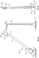
- first and second rear tensioning assemblies 140A and 140B are illustrated in detail. Discussion of one of the first or second rear tensioning assemblies 140A or 140B, respectively, applies to the other of the first or second rear tensioning assemblies 140A or 140B, respectively, unless otherwise noted.
- Each of the first and second rear tensioning assemblies 140A and 140B, respectively, has a linear actuator, indicated generally at 196, a top link 198, and a rear link 200.
- the top link 198 has a second contact surface 202 configured to engage with the first contact surface 194 of the pocket portion 190. As illustrated, the second contact surface 202 is an arcuate surface, though other shapes may be used.
- first pivot connection 204 connects the linear actuator 196 and the top link 198 while allowing rotational movement between the linear actuator 196 and the top link 198.
- second pivot connection 206 connects the top link 198 and the rear link 200 while allowing rotational movement between the top link 198 and the rear link 200.
- a pivot assembly 208 connects the linear actuator 196 to the flatbed trailer 104.
- the pivot assembly 208 is rotationally fixed to the bed portion 106 of the flatbed trailer 104 and a pivot connection 210 connects the linear actuator 196 and the pivot assembly 208 while allowing rotation of the linear actuator 196 relative to the pivot assembly 208.
- a mounting assembly 212 rigidly connects the rear link 200 to the flatbed trailer 104.
- the mounting assembly 212 is rotationally fixed to the rear link and relative to the bed portion 106.
- the rear link 200 is restrained by the mounting assembly 212 from movement, such as linear movement along the trailer and fixed in at least the plane defined by the support surface 118 of the bed portion 106.
- the linear actuator 196 includes first and second linear actuator portions 214 and 216, respectively.
- the linear actuator 196 may be a ball screw.
- the first linear actuator portion 214 is selectively actuated - e.g., rotated - by an actuator 218, such as a motor and gearbox assembly, to extend or retract relative to the second linear actuator portion 216 along a linear actuator axis 220, such as in a telescoping manner.
- the actuator 218 is an electric motor.
- the actuator 218 may be a hydraulic or pneumatic cylinder.
- the top link 198 rotates along an arc 222.
- the top link 198 moves along the arc 222 towards the rear portion 116 of the flatbed trailer 104.
- the top link 198 moves along the arc 222 away from the rear portion 116 (and towards the front portion 110 of the flatbed trailer 104).
- first and second rear tensioning assemblies 140A and 140B extend upwardly from the bed portion 106.
- the first and second rear tensioning assemblies 140B and 140B, respectively, are at an angle 224 from the support surface 118, wherein the illustrated angle 224 is less than 90°.
- the illustrated angle 224 is 88°.
- the first and second rear tensioning assemblies 140B and 140B may extend at an acute or obtuse angle or at a right angle from the trailer bed 106, if desired.
- FIG. 9A illustrates the first rear tensioning assembly 140A in a first position, which is a non-tensioning, or release position.
- FIG. 10 illustrates the first tensioning assemblies 140A in a second position, which is a tensioning, locked or applied position.
- the first and second rear tensioning assemblies 140A and 140B are preferably in the first position.
- the first and second rear tensioning assemblies 140A and 140B are in the second position.
- the first and second rear tensioning assemblies 140A and 140B selectively move between the first and second positions by the linear actuator 196 displacing the top link 198 along the arc 222.
- the linear actuator 196 has displaced the top link 198 along the arc 222 such that the second contact surface 202 is in contact with and bears upon the first contact surface 194 of the tensioning receiver 186.
- the contact between the first and second contact surfaces 194 and 202, respectively is a tangential contact point 226.
- the tangential point of contact permits contact between the two components at a discrete point which may be at a variable position along the first and second contact surfaces 194 and 202. This variable location of the contact point absorbs tolerances associated with the rolling tarp and trailer structures.
- the tangential contact point 226 may be provided by the first contact surface 194 being arcuate and the second contact surface 202 being flat or otherwise planar. It should be understood that other geometries capable of generating a variable contact point between two contacting surfaces may be used for the first and second contacting surfaces 194 and 202 and remain within the scope of the invention.
- the first and second rear tensioning assemblies 140A and 140B respectively, develop a tensioning force in the direction 146 to displace, push, press, or otherwise move the rear bow 124 in the direction 146.
- the front tensioning assembly 128 is operated to latch the front bow 120 to the bulkhead 126. Then, the rear bow 124 is propelled to the rear portion 116 of the flatbed trailer 104 by the roller motor assemblies 136, which in turn moves the intermediate bows 122 along the length of the trailer.
- the first and second rear tensioning assemblies 140A and 140B are actuated to displace the rear bow 124 further in the direction 146 while the front tensioning assembly 128 restrains the front bow 120 from movement in the direction 146. This tensions the tarp section or tarp sheet of the rolling tarp system 102 and places the rolling tarp system 102 in the deployed state.
- the first and second rear tensioning assemblies 140A and 140B are operated to be released or otherwise not displace and tension the rear bow 124 in the direction 146, the roller motor assemblies 136 propel the rear bow 124 from the rear portion 116 to the front portion 110, and the front tensioning assembly 128 is operated to unlatch the front bow 120 from the bulkhead 126.
- the rear bow 124 is moved by the roller motor assemblies 136.
- the rear bow 124 may be moved by other than the roller motor assemblies 136, such as during a loss of power or a malfunction, where the rear bow 124 may be manually moved on the flatbed trailer 104.
- the deployment system 100 is arranged on the flatbed trailer 104 such that the front tensioning assembly 128 is at the front portion 110 of the flatbed trailer 104 and the rear tensioning assembly 138 is at the rear portion 116 of the flatbed trailer 104.
- the front tensioning assembly 128 may be at the rear portion 116 and the rear tensioning assembly 138 may be at the front portion 110.
- FIGS. 11-14 there is illustrated a second embodiment of a rolling tarp deployment system, indicated generally at 300, in accordance with the invention.
- the roller tarp deployment system 300 is for a roller tarp system and is a variation of the deployment system 100 previously discussed with reference to FIGS. 1-10 .
- like reference numerals, incremented by 200, designate corresponding parts in the drawings and detailed description thereof will be omitted.
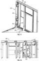
- a torque generating device 334 of a front tensioning assembly 328 includes an electric motor 478 which may also include a gearbox.
- a driveline 332 is supported by support brackets 480, which may be pillow block bearings or bushings if desired.
- One or more guard portions 482 restrain any load or cargo from contacting the front tensioning assembly 328.
- a latch assembly 484 which may be a worm and sector gearbox drive, has an arm 486. In a latched state of the latch assembly 484, shown in FIG. 12 , the arm 486 engages a hook end similar to the hook 152 into and out of engagement with a corresponding latch pin or striker, similar to the latch pin 152.
- roller motor assembly 336 of the deployment system 300.
- the roller motor assembly 336 has a spring assembly, indicated generally at 488.
- the spring assembly 488 maintains contact between the roller motor assembly 336 and a top surface 378 of a track assembly.
- the spring assembly 488 provides damping for the roller motor assembly 336 and may also provide contact pressure sufficient for a motor 374 to drive a roller 376 against the track surface.
- the roller motor assembly 336 is mounted to a bow of the rolling tarp system - e.g., a front bow or a rear bow - by a connection 490.
- the connection 490 allows rotational movement of the roller motor assembly 336 about the connection 490.
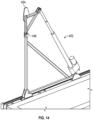
- the rear tensioning assembly 492 has a tensioning contact portion 494.
- the rear tensioning assembly 492 rotates the tensioning contact portion 494 about a pivot connection 496 to contact and displace a tensioning receiver on the rear bow to tension the roller tarp system.
- the deployment system 500 deploys a rolling tarp system, indicated generally at 502.
- the deployment system 500 is not limited to use with the specific rolling tarp system 502 illustrated. Instead, the deployment system 500 may be used with rolling tarp systems other than the illustrated rolling tarp system 502.
- the deployment system 500 deploys the rolling tarp system on a transport system, such as a flatbed trailer, indicated generally at 504.
- the flatbed trailer 504 is conventional in the art, with a bed portion, indicated generally at 506, and a towing element 508 (shown by hidden lines) attached to the trailer.
- the towing element may be configured in any suitable manner, but may be a kingpin associated with a fifth-wheel towing system, a gooseneck towing system, a hitch type trailer towing system, and the like.
- the towing element attached to the trailer may be positioned on an underside or a leading edge of the bed portion 506.
- the towing element 508 generally defines a front portion 510 of the flatbed trailer 504, which may be indicative of a direction in which the flatbed trailer 504 is intended to be towed.
- first and second side portions 512 and 514, respectively, and a rear portion 516 of the flatbed trailer 504 are conventionally defined relative to the front portion 510.
- the bed portion 506 further defines a support or deck surface 518 that forms support for transporting goods thereon.
- the deployment system 500 is illustrated for use with the flatbed trailer 504, any suitable type of transport system capable of accommodating the rolling tarp system 502 may be used.
- the deployment system 500 may be used with other transport systems such as a railcar, handcart, or other structure.
- the towing element 508 may be adjacent to or connected with a cab portion of a vehicle, such as a stake truck.
- the rolling tarp system 502 includes a plurality of bows including a front bow 520, at least one intermediate bow similar to intermediate bows 122 described above, and a rear bow 524.
- the intermediate bows are interlinked or otherwise connected with and between the front and rear bows 520 and 524, respectively, such that the front bow 520, intermediate bows, and rear bow 524 may move together.
- the interlinking component may be a tarp sheet.
- cables, folding linkages, or other structures may interconnect the bow, alone or in conjunction with the tarp sheet.
- the front bow 520, intermediate bows, and rear bow 524 are collectively deployable between a compressed or collapsed state and a deployed or expanded state.
- the front bow 520, intermediate bows, and rear bow 524 are positioned tightly together and the flatbed trailer 504 is substantially uncovered.
- the front bow 520, intermediate bows, and rear bow 524 are distributed or otherwise arrayed along a length of the flatbed trailer 504 between the front and rear portions 510 and 516, respectively.
- the front and rear bows 520 and 524, respectively are in a partially deployed state on the flatbed trailer 504 that is between the compressed and deployed states and in which the flatbed trailer is partially uncovered.
- a tarp section is typically attached over or between the front bow 520, intermediate bows, and rear bow 524.
- the tarp section may interlink the front bow 520, intermediate bows, and rear bow 524.
- the rolling tarp system 502 also includes a bulkhead 526 attached to the front bow 520.
- the bulkhead 526 is preferably also fixed in position in a plane defined by the support surface 518.
- the bulkhead 526 may be provided differently than as illustrated.
- the deployment system 500 includes first and second front tensioning assemblies, indicated generally at 528A and 528B, respectively. Discussion of one of the first and second front tensioning assemblies 528A and 528B, respectively, also applies to the other of the first and second front tensioning assemblies 528A and 528B, respectively, unless otherwise noted.
- the first and second front tensioning assemblies 528A and 528B, respectively, will be discussed in detail with reference to FIGS. 16 and 17 .
- the deployment system 500 further includes first and second rear tensioning assemblies, indicated generally at 530A and 530B, respectively. Discussion of one of the first and second rear tensioning assemblies 530A and 530B, respectively, also applies to the other of the first and second rear tensioning assemblies 530A and 530B, respectively, unless otherwise noted.
- the first and second rear tensioning assemblies 530A and 530B, respectively, will be discussed in detail with reference to FIGS. 18 and 19 .
- the deployment system 500 also includes electric roller motor assemblies, indicated generally at 532.
- the electric roller motor assemblies 532 may be used to deploy or compress the rolling tarp system 502.
- the roller motor assemblies are provided for the front and rear bows 520 and 524, respectively. The roller motor assemblies will be discussed in detail with reference to FIG. 21 .
- the first front tensioning assembly 528A includes a pivotally mounted, electric, front tensioning actuator motor 534, pivotally mounted hooks 536A-536D, and an actuator linkage 538 mounted to the front bow 520.
- the actuator motor 534, hooks 536, and actuator linkage 538 are mounted to opposing vertical portions of the front bow 520.
- the front bow 520 further has at least one of the roller motor assemblies 532 as illustrated for movement of the front bow 520 along the flatbed trailer 504.
- the front bow 520 is also provided with a front electronic controller 540 for automated operation of the first and second front tensioning assemblies 528A and 528B, respectively, during deployment and compression of the deployment system 500 - e.g., operating the actuator motor 534 to actuate the hooks 536 - as well as operation of the roller motor assemblies 532 to move the front bow 520.
- the front electronic controller 540 also preferably coordinates operating of electronic stops, alarms, and/or warning lights for the deployment system 500.
- the first front tensioning assembly 528A further includes hook receiver assemblies 542 and a receiver linkage 544.
- a shaft 546 connects the hook receiver assemblies 542A-542D corresponding to the hooks 536A-536D of the first and second front tensioning assemblies 528A and 528B, respectively.
- the first front tensioning assembly 528A further includes a manual drive assembly, indicated generally at 548, mounted to the bulkhead 526 that is for manually actuating the hook receiver assemblies 542.
- the manual drive assembly 548 includes a hand crank receiver 550, a bevel gear hub 552, and a drive shaft 554.
- the hand crank receiver 550 allows the manual drive assembly 548 to be operated from the ground outside the flatbed trailer 504.
- Gaskets, baffles, or other cushioning and/or sealing structures 556 may be provided between the front bow 520 and the bulkhead 526.
- the gaskets 556 may be provided on both of the front bow 520 and the bulkhead 526 or on only one of the front bow 520 or the bulkhead 526.
- the sealing structures, particularly where two opposing seals 556 are provided on the front bow 520 and bulkhead 526, can provide a safety function should an operator place an arm or leg between the seals during the closing operation by preventing the hooks from engaging the receivers. Should a smaller appendage, such as a finger or hand, be inserted between the gaskets, the thickness of the gaskets provides sufficient cushioning to accommodate the appendage and prevent injury.
- the roller motor assemblies 532 are first used to position the front bow 520 adjacent the bulkhead 526 such that the hooks 536A-536D may be actuated to engage the hook receiver assemblies 542A-542D. Then, the actuator motor 534 is actuated to rotate each of the hooks 536A-D to engage with the corresponding hook receiver assemblies 542A-D. Second and third hooks 536B and 536C, respectively, are directly actuated by the actuator motors 534 and first and fourth lower hooks 536A and 536D, respectively, are indirectly actuated by the actuator motor 534 via the actuator linkage 538, though any actuation arrangement may be used.
- the hooks 536A-D are actuated to rotate in a first direction 557 about a first pivot 558.
- the hook receiver assemblies 542A-D are mounted on the bulkhead 526 such that the hook receiver assemblies 542A-D rotate in a second direction 560 about a second pivot 562 when the hooks 536A-D contact and engage with the hook receiver assemblies 542A-D. Rotation of the hook receiver assemblies 542A-D in the second direction 560 takes up slack between the hooks 536A-D and the hook receiver assemblies 542A-D.
- the first and second front tensioning assemblies 528A and 528B may be manually actuated to release the first and second front tensioning assemblies 528A and 528B, respectively.
- the drive shaft 554 is rotated via a hand crank in the hand crank receiver 550. Rotation of the drive shaft 554 linearly translates a rotationally restrained nut 564 along the drive shaft 554. The linear movement of the nut 564 along the drive shaft 554 results in a manual drive linkage 566 rotating a first hook receiver assembly 542A in the second direction 560 about the second pivot 562.
- the other hook receiver assemblies 542B-D are also rotated in the second direction 560 via the receiver linkage 544 and shaft 546.
- a fourth receiver assembly 542D is connected to the third hook receiver assembly 542C by a receiver linkage 544.
- hooks 536 and four corresponding hook receiver assemblies 542 are provided for the deployment system 500.
- more or fewer than four hooks 536 and/or hook receiver assemblies 542 may be provided for the deployment system 500.
- the second rear tensioning assembly 530B includes a pivotally mounted, electric, rear tensioning actuator motor 568 that linearly extends or retracts a rod 570 to which a tension link 572 is pivotally connected. While the tension link 572 is illustrated with an arcuate shape, such is not required.
- a tension link support 574 is pivotally connected to the tension link 572 and a tension link reinforcement 576 is rigidly connected to the tension link 572.
- the tension link support 574 is pivotally mounted to the rear bow 524 and hinged to move in consort with the tension link reinforcement 576, such as a four bar linkage arrangement.
- the tension link 572 and the tension link reinforcement 576 may be formed as a single, unitary, or otherwise monolithic member.
- the tension link support 574 is pivotally connected to the tension link reinforcement 576 by a load cell link 578.
- the actuator motor 568, rod 570, tension link 572, tension link support, tension link reinforcement 576, and load cell link 578 are supported by the rear bow 524.
- the tension link support 574 has a greater dimension - i.e., thickness - in a direction transverse to the intended direction of towing than the tension link reinforcement 576 such that the tension link support 574 and the tension link reinforcement 576 form a pocket, indicated generally at 580.
- the pocket 580 will be discussed further with reference to FIG. 19 .
- the first rear tensioning assembly 530A further includes a first rear tensioning receiver assembly, indicated generally at 582A.
- the first tensioning receiver assembly 582A is mounted to the bed portion 506. Discussion of one of the first or second tensioning receiver assemblies 582A or 582B, respectively, also applies to the other of the first or second tensioning receiver assemblies 582A or 582B, respectively, unless otherwise noted.
- the first tensioning receiver assembly 582A includes a contact plate 584 rigidly fixed to a first structural member 586.
- a second structural member 588 is pivotally connected to the first structural member 586.
- the first structural member 586 is pivotally fixed to a first base member 590 and the second structural member 588 is pivotally connected to a second base member 592.
- the first base member 590 is fixed to the bed portion 506.
- the second base member 592 is fixed to the bed portion 506 and an adjustable hinge 592A has a sliding connection to the second base member 592.
- a position of the adjustable hinge 592A relative to the second base member 592 is adjusted by a threaded rod 594. As illustrated, the threaded rod 594 is manually adjustable by a hand crank (not shown).
- the threaded rod 594 may be adjustable by a motor.
- the adjustable hinge 592A may be adjusted in a third direction 596 relative to the second base member 592, and thus the bed portion 506, such that the contact plate 584 rotates in a fourth direction 598 and a vertical elevation 600 of the contact plate 584 is adjusted.
- the vertical elevation 600 of the contact plate 584 is coordinated with a similar vertical elevation of the pocket 580.
- a third distance between the contact plates 584 of the first and second tensioning receiver assemblies 582A and 582B, respectively, is greater than a fourth distance between the first base members 590 of the first and second tensioning receiver assemblies 582A and 582B, respectively.
- the third and fourth distances are parallel and transverse to the intended direction of towing for the flatbed trailer 504.
- the first and second tensioning receiver assemblies 582A and 582B, respectively, are mounted to the bed portion 506 such that the contact plates 584 are positioned over the first and second sides 512 and 514 of the bed portion 506.
- the distance between contact plates 584 of the spaced apart first and second tensioning receiver assemblies 582A and 582B is within the envelope of the tarp and rear bow assembly and positioned generally in a plane defined by the pivot points of the linkages.
- the contact plates 584 engage pockets 580 of the associated tensioning receiver assemblies 582A and 582B.
- the roller motor assemblies 532 are first used to position the rear bow 524 at the rear portion 516 of the bed portion 506. With the rear bow 524 in position relative to the first and second tensioning receiver assemblies 582A and 582B, respectively, the rolling tarp system 502 is tensioned.
- the actuator motor 568 is operated to rotate the tension link support 574 and the tension link reinforcement 576 in a fifth direction 602.
- the tension link support 574 rotates about a third pivot 604 and the tension link reinforcement 576 rotates about a fourth pivot 606.
- the actuator motor 568 rotates the tension link support 574 and the tension link reinforcement 576 from a first position (shown in FIG. 18 ) and towards a second position (shown in FIG. 19 with the pivotally mounted actuator motor 568 also rotated) such that the contact plate 584 enters the pocket 580 and contacts the tension link support 574.
- the contact plate 584 contacts the tension link support 574 as shown in FIG. 19 .
- the rear bow 524 is moved in a sixth direction 608 that is away from the front bow 520.
- the sixth direction 608 is parallel to the intended direction of towing for the flatbed trailer 504.
- Movement of the rear bow 524 in the sixth direction 608 introduces a tensioning force in the rolling tarp system 502. Movement of the tension link support 574 and the tension link reinforcement 576 towards the front portion 510 increases the tensioning force. Movement of the tension link support 574 and the tension link reinforcement 576 away from the front portion 510 decreases the tensioning force.
- the load cell link 578 is used to measure the tensioning force so that a desired tensioning force may be realized.
- the load cell link 578 is used so that the first and second rear tensioning assemblies 530A and 530B, respectively, may achieve a preset tensioning load.
- the load cell link 578 may be used to maintain and/or adjust the tensioning force to the preset tensioning load while the deployment system 500 is deployed - e.g., the tensioning force may be maintained or adjusted while the flatbed trailer 504 is being transported.
- roller motor assembly 532 for the deployment system 500.
- the roller motor assembly 532 illustrated in FIG. 21 may be mounted to and propel the front or rear bows 520 or 524, respectively, or both bows.
- the roller motor assembly 532 includes an electric drive motor 612 driving a drive wheel 614.
- the drive wheel 614 propels the roller motor assembly 532 on a track 616 (shown in FIG. 25 ).
- the drive wheel 614 is an anti-slip wheel, though such is not required.
- the drive wheel 614 may be a toothed wheel that engages a corresponding and mating toothed track (not shown) attached to the bed portion 506.
- Lower rollers, indicated generally at 618, are within track passages below an upper surface of the track 616 to provide stability for the roller motor assembly 532.
- a manual release 620 selectively operates a clamping mechanism to engage or disengage the drive wheel 614 from the track 616.
- the manual release 620 engages the drive wheel 614 by pressing the drive wheel 614 against the track 616 and provides consistent traction between the drive wheel 614 and the track 616.
- the drive wheel 614 may be disengaged from the track 616, by using the manual release 620, to allow the front bow 520, intermediate bows, or rear bow 524 to be moved manually along the bed portion 506.
- the roller motor assembly 532 also includes a limit switch 621 for determining and controlling a position of the roller motor assembly 532 on the flatbed trailer 504.
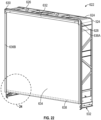
- the deployment system 500 may also include a rear cover assembly, indicated generally at 622.
- the rear cover assembly 622 is illustrated in a deployed position in FIG. 22 and in a retracted position in FIG. 23 .
- the rear cover assembly 622 is attached to the rear bow 524.
- the first and second rear tensioning assemblies 530A and 530B, respectively, are omitted for clarity.
- the rear cover assembly 622 is mounted to an extension cover 624 that is in turn mounted to the rear bow 524.
- the extension cover 624 is provided on the rear bow 524 as illustrated.
- the extension cover 624 may be provided other than as illustrated.
- the extension cover 624 may be provided only for a top side 626 of the rear bow 524.
- the rear cover assembly 622 includes first and second electric motors 628 and 630, respectively, which are connected by a rod 632, and a cover 634. Alternatively, more or fewer than the first and second electric motors 628 and 630, respectively, may be provided. As illustrated, the cover 634 is a soft, non-rigid cover. When the cover 634 is the soft, non-rigid cover illustrated, the first and second electric motors 628 and 630, respectively, are operated to roll the cover 634 on to the rod 632 from the deployed position in FIG. 22 to the retracted position in FIG. 23 . Alternatively, the cover 634 may be a rigid or partially rigid cover. As a non-limiting example, the cover 634 may be a plurality of rigid horizontal slats, connected by flexible fabric pleats, and raised and compressed in an accordion manner.
- first and second vertical members 636A and 636B, respectively, of the extension cover 624 are C-shaped channels that guide movement of the cover 634 up and down between the deployed and retracted positions.
- the cover 634 is provided with a bar 638 (shown by a dashed line in FIG. 22 ) at an end opposite the rod 632.
- the bar 638 provides weighting of the cover 634.
- rollers 640 are provided on opposite ends of the bar 638 to roll in the C-shaped channels of the first and second vertical members 636A and 636B, respectively.
- a stabilizer member 642 is provided for the rollers 640.
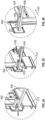
- FIG. 24 illustrates the bar 638 in a locked down position.
- the bar 638 is in the locked down position when the rear cover assembly 622 is in the deployed position.
- FIG. 25 illustrates the bar 638 in a free movement position. The bar 638 is in the free movement position when the rear cover assembly 622 is moved between the deployed and retracted positions.
- FIG. 26 illustrates the bar 638 ready to be placed in a locked up position. To place the bar 638 into the locked up position, the bar 638 is moved in a forward direction 644 and into a recess 646. The cover 634 is omitted from FIGS. 24-26 for clarity.
- the deployment system 500 may be actuated by an operator, such as a driver or tractor/trailer operator with the electronic or manual systems described above.
- the deployment system 500 may be coupled to a controller of an autonomous vehicle, such as an autonomous tractor-trailer system, to be deployed by the vehicle rather than a human operator.
- the vehicle controller may respond to an input, such as an indication of arrival at the desired destination, and contact the recipient and autonomously activating the deployment system to permit loading or unloading of goods.
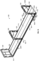
- FIGS. 27-30 there is illustrated a fourth embodiment of a rolling tarp deployment system, indicated generally at 700, in accordance with the invention.
- the roller tarp deployment system 700 is for a roller tarp system and is a variation of the deployment system 500 previously discussed with reference to FIGS. 15-26 .
- like reference numerals, incremented by 200, designate corresponding parts in the drawings and detailed description thereof will be omitted.
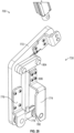
- the front tensioning assembly 728 includes an actuator motor 734 positioned above hooks 736.
- the actuator motor 734 rotates the hooks 736 in a first direction 757.
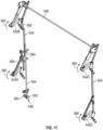
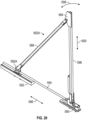
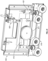
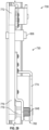
- FIGS. 28-30 there is illustrated a portion of a rear tensioning assembly 730 that includes a tension link 772, a tension link support 774, a tension link reinforcement 776, and a load cell link 778.
- the tension link support 774 defines a pocket 780.
- Within the pocket 780 is a bearing member 848.
- the pocket 780 receives a corresponding contact plate. The contact plate contacts the bearing member 848.
Description
- This application claims the benefit of
U.S. Provisional Application No. 62/721,194, filed August 22, 2018 U.S. Provisional Application No. 62/644,884, filed March 19, 2018 - This invention relates in general to deployment systems for shipping protection systems, and in particular, to a deployment system for a rolling tarp system.
- Flatbed trailers are often used to haul loads that are bulky or heavy. These loads often have handling characteristics that rely on access to open sides of the flatbed trailer for loading and unloading. The flatbed trailers provide this open access for handling freight but lack a structure for conveniently covering the loads from weather or for privacy. Thus, tarps are often used to protect freight carried on a flatbed trailer. Sometimes the tarps are applied directly over the loads. Other tarp coverings define an enclosed cargo space and provide access to the cargo therein. One such type of accessible tarp covering is a rolling tarp system that relies on bows and other support structures secured to guide tracks to create a space over the trailer and support one or more tarp sections or sheets.
- The rolling tarp systems are operable between a deployed state in which the rolling tarp system is expanded to cover the load on the flatbed trailer and a compressed state in which the rolling tarp system is collapsed to expose the load for access. As discussed, the rolling tarp systems typically comprise a plurality of bows and a tarp section covering and interlinking the bows. Deployment of such a rolling tarp system requires positioning, by rolling on the guide tracks, the bows into position along a length of the flatbed trailer. Once the bows are in position, the tarp section is tensioned until tight on the bows. The positioning of the bows and tensioning of the tarp section are manual processes. The time required to perform the positioning and tensioning may delay shipping times and schedules. Thus, it would be desirable to have a more efficient system for deploying the rolling tarp system on the flatbed trailer.
US8491032 discloses a retractable tarp system having automated closing mechanisms used in conjunction with the front and rear of a truck or vehicle-pulled trailer. - This invention relates in general to deployment systems for shipping protection systems. In particular, this invention relates to an improved deployment system for a rolling tarp system. In one aspect, the rolling tarp deployment system includes a flatbed trailer having a deck space configured to accommodate cargo, a bulkhead fixed to the flatbed trailer, first and second bows movable along the flatbed trailer, first and second tensioning assemblies, and a flexible cover. The first tensioning assembly has a first member secured to the first bow, a second member secured to the bulkhead, and a first actuator configured to engage the first and second members to restrain the first bow to the bulkhead. The second tensioning assembly has a third member secured to the second bow, a fourth member fixed to the flatbed trailer, and a second actuator configured to engage the third and fourth members and move the second bow away from the bulkhead. The flexible cover is tensioned by the second bow moving away from the bulkhead when the first and second members are engaged and the third and fourth members are engaged. Motorized roller assemblies are provided for each of the first and second bows. The motorized roller assemblies are configured to move the first and second bows along the flatbed trailer.
- In a particular embodiment of this aspect, the first actuator moves the second member to engage the first member and the second actuator moves the fourth member to engage the third member. In a different embodiment of this aspect, the first actuator moves the first member to engage the second member and the second actuator moves the third member to engage the fourth member. Furthermore, this aspect may be provided with a rear cover assembly on the second bow.
- Various aspects of this invention will become apparent to those skilled in the art from the following detailed description of the preferred embodiment, when read in light of the accompanying drawings.
-
-
FIG. 1 is a perspective view of a first embodiment of a rolling tarp deployment system in accordance with the invention. -
FIGS. 2 and3 are perspective views of a front tensioning assembly of the rolling tarp deployment system ofFIG. 1 . -
FIGS. 4 and5 are enlarged perspective views of a latch assembly of the front tensioning assembly ofFIGS. 2 and3 . -
FIG. 6 is a perspective view showing a motorized roller assembly of the rolling tarp deployment system ofFIG. 1 . -
FIG. 7 is a perspective view of a first portion of a rear tensioning assembly of the rolling tarp deployment system ofFIG. 1 . -
FIG. 8 is a perspective view of a second portion of the rear tensioning assembly. -
FIGS. 9A and 9B are elevation views of the second portion of the rear tensioning assembly in a first position. -
FIG. 10 is an elevation view of the second portion of the rear tensioning assembly ofFIGS. 9A and 9B in a second position. -
FIGS. 11 and 12 are perspective views of a front tensioning assembly of a rolling tarp deployment system in accordance with a second embodiment of the invention. -
FIG. 13 is a perspective view of a motorized roller assembly for the rolling tarp deployment system in accordance with the second embodiment of the invention. -
FIG. 14 is a perspective view of a rear tensioning assembly of the rolling tarp deployment system in accordance with the second embodiment of the invention. -
FIG. 15 is a perspective view of a third embodiment of a rolling tarp deployment system in accordance with the invention. -
FIGS. 16 and17 are perspective views of a front tensioning assembly of the rolling tarp deployment system ofFIG. 15 . -
FIG. 18 is an elevation view of a rear tensioning assembly of the rolling tarp deployment system ofFIG. 15 in a first position. -
FIG. 19 is an elevation view of the rear tensioning assembly ofFIG. 18 in a second position. -
FIG. 20 is an elevation view of a tensioning receiver assembly of the rear tensioning assembly. -
FIG. 21 is an elevation view of a motorized roller assembly of the rolling tarp deployment system ofFIG. 15 . -
FIG. 22 is a first elevation view of a rear cover assembly of the rolling tarp deployment system ofFIG. 15 in a first position. -
FIG. 23 is a second elevation view of the rear cover assembly ofFIG. 22 in a second position. -
FIG. 24 is an enlarged portion ofFIG. 22 . -
FIG. 25 is an enlarged portion of the rear cover assembly ofFIGS. 22 and23 in a free movement position. -
FIG. 26 is an enlarged portion ofFIG. 23 . -
FIG. 27 is a perspective view of a front tensioning assembly of a rolling tarp deployment system in accordance with a fourth embodiment of the invention. -
FIGS. 28-30 are perspective views of a rear tensioning assembly of the rolling tarp deployment system in accordance with the fourth embodiment of the invention. - Referring now to
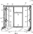
FIG. 1 , there is illustrated a rolling tarp deployment system, indicated generally at 100, in accordance with a first embodiment of the invention. Thedeployment system 100 deploys a rolling tarp system, indicated generally at 102. Thedeployment system 100 is not limited to use with the specificrolling tarp system 102 illustrated. Instead, thedeployment system 100 may be used with rolling tarp systems other than the illustratedrolling tarp system 102. As a non-limiting example, thedeployment system 100 may be used with the rolling tarp system disclosed inU.S. Patent No. 9,033,393 deployment system 100 deploys the rolling tarp system on a transport system, such as a flatbed trailer, indicated generally at 104. - The
flatbed trailer 104 is conventional in the art, with a bed portion, indicated generally at 106, and a towing element 108 (shown by hidden lines). As a non-limiting example, the towingelement 108 may be a fifth-wheel hitch unit or a trailer hitch receiver. The towingelement 108 defines afront portion 110 of theflatbed trailer 104, which may be indicative of a direction in which theflatbed trailer 104 is intended to be towed. Opposing first andsecond side portions rear portion 116 of theflatbed trailer 104 are conventionally defined relative to thefront portion 110. Thebed portion 106 further defines a support ordeck surface 118 that forms support for transporting goods or cargo thereon. Although thedeployment system 100 is illustrated for use with theflatbed trailer 104, any suitable type of transport system capable of accommodating the rollingtarp system 102 may be used. As non-limiting examples, thedeployment system 100 may be used with other transport systems such as a railcar, handcart, or other structure. In certain embodiments, the towingelement 108 may be a cab portion of a vehicle, such as a stake or flatbed truck. - In one embodiment, the rolling
tarp system 102 includes a plurality of bows including afront bow 120, at least one intermediate bow, indicated generally at 122, and arear bow 124. The intermediate bows 122 are interlinked or otherwise connected with the front andrear bows rear bows rear bows FIG. 1 , the front, intermediate, andrear bows flatbed trailer 104. In the deployed state, the front, intermediate, andrear bows flatbed trailer 104 between the front andrear portions rear bows rear bows tarp system 102 also includes abulkhead 126 attached to thefront bow 120. Thebulkhead 126 is preferably also fixed to theflatbed trailer 104, typically at thefront portion 110 and generally perpendicular to thesupport surface 118. Thebulkhead 126 may be provided or configured differently than as illustrated. - The
deployment system 100 includes a front tensioning assembly, indicated generally at 128. Thefront tensioning assembly 128 includes latch assemblies, indicated generally at 130, adriveline 132 supplying torque to thelatch assemblies 130, and atorque generating device 134 supplying the torque to thedriveline 132. Thefront tensioning assembly 128 will be discussed in detail with reference toFIGS. 2-5 . Thedeployment system 100 also includes roller motor assemblies, indicated generally at 136. Theroller motor assemblies 136 will be discussed in detail with reference toFIG. 6 . Thedeployment system 100 further includes a rear tensioning assembly, indicated generally at 138. As illustrated, therear tensioning assembly 138 includes first and second rear tensioning assemblies, indicated generally at 140A and 140B, respectively. The first and secondrear tensioning assemblies FIGS. 7-10 . - Referring now to
FIGS. 2 and3 , thefront tensioning assembly 128 is shown in detail. Thefront tensioning assembly 128 may include more or less than the fourlatch assemblies 130 illustrated. Each of thelatch assemblies 130 comprises first andsecond latch portions first latch portions 142 are mounted to thebulkhead 126 and thesecond latch portions 144 are mounted to thefront bow 120. The first andsecond latch portions front bow 120 from movement in adirection 146 along the length of theflatbed trailer 104 and away from the bulkhead 126 (from thefront portion 110 to therear portion 116 shown inFIG. 1 ). Thelatch assemblies 130 will be discussed further with reference toFIGS. 4 and5 . - As discussed, the
driveline 132 supplies the torque to thelatch assemblies 130 from thetorque generating device 134. To supply the torque, thedriveline 132 connects each of thelatch assemblies 130 to thetorque generating device 134. As illustrated, thedriveline 132 supplies the torque to thelatch assemblies 130 in series. Also, as illustrated, thedriveline 132 includes agearbox 148, having a gear set such as bevel gears, to transmit torque from one side of thefront bow 120 to the other. In the illustrated embodiment, thedriveline 132 extends between generally vertical and generally horizontal orientations (relative to the support surface 118) by way of thegearboxes 148. Alternatively, thedriveline 132 may supply the torque to thelatch assemblies 130 via an arrangement other than as illustrated. Alternatively, as a non-limiting example, thedriveline 132 may supply the torque to at least some of thelatch assemblies 130 via a parallel arrangement or a portion of thedriveline 132 to thelatch assemblies 130 corresponding to thesecond side portion 114 of theflatbed trailer 104 may be on an underside of thebed portion 106. Preferably, thedriveline 132 includes a threaded screw or worm portion, which may be part of thefirst latch portion 142 at each of thelatch assemblies 130 to supply or transfer the torque from thedriveline 132 to thelatch assemblies 130. Alternatively, other suitable gearings or drive means may be used for thedriveline 132 to transfer the torque to each of thelatch assemblies 130. - As discussed, the
latch assemblies 130 are linked by thedriveline 132. This results in thelatch assemblies 130 also being operatively linked. When the torque from thetorque generating device 134 is supplied by thedriveline 132 to thelatch assemblies 130, all of thelatch assemblies 130 so supplied are concurrently actuated. - The
torque generating device 134 selectively generates and supplies the torque to thedriveline 132. Thetorque generating device 134 preferably generates the torque in opposing directions - e.g., clockwise and counterclockwise. Thetorque generating device 134 is illustrated as a motor, preferably an electric motor. Alternatively, thetorque generating device 134 may be other than the illustrated motor. As a non-limiting example, thetorque generating device 134 may be a hand crank, hydraulic motor, pneumatic motor, or other motive device. Furthermore, when thetorque generating device 134 is a motor, such as the electric motor, the hand crank may be provided as a backup actuation system. - As illustrated, a single
torque generating device 134 supplies the torque to all of thelatch assemblies 130. Alternatively, more than onetorque generating device 134 may separately provide torque to subgroupings of thelatch assemblies 130, wherein the torque is supplied to the subgroupings byseparate drivelines 132 or by direct connection to thetorque generating devices 134. As a non-limiting example, thelatch assemblies 130 corresponding to thefirst side portion 112 of theflatbed trailer 104 may have torque supplied by a firsttorque generating device 134 and thelatch assemblies 130 corresponding to thesecond side portion 114 of theflatbed trailer 104 may have torque separately supplied by a secondtorque generating device 134. Alternatively, each of thelatch assemblies 130 may have its owntorque generating device 134, such as the electric motor. - Referring now to
FIGS. 4 and5 , thelatch assemblies 130 are shown in detail. As illustrated, thefirst latch portion 142 includes astop 150, which may be a striker or latch pin structure, and thesecond latch portion 144 includes an engagement portion 152 (shown by hidden lines as a hook structure) that engages thestop 150. Thelatch assembly 130 is in a latched state when thestop 150 is engaged with theengagement portion 152 and in an unlatched state when theengagement portion 152 is disengaged from thestop 150. Theengagement portion 152 engaging thestop 150 restrains thefront bow 120 from movement away from thebulkhead 126 in thedirection 146. As illustrated, thestop 150 is a pin or bar and theengagement portion 152 is a rotating hook. Alternatively, thestop 150 may be other than the illustrated pin and theengagement portion 152 other than the illustrated rotating hook to restrain thefront bow 120 from movement away from thebulkhead 126 in thedirection 146. - The
first latch portion 142 includes an actuator gearing 154 (shown by hidden lines). Preferably, theactuator gearing 154 includes a reduction gearing, such a worm and sector gear set, bevel gear set, or other angled drive element. As a non-limiting example, the reduction gearing may be a 60:1 gear reduction. As shown inFIGS. 4 and5 , theactuator gearing 154 diverts a portion of the torque supplied by thedriveline 132 to move thehook 152 into and out of engagement with thelatch pin 152. As will be discussed, the actuator gearing 154 uses the torque supplied by thedriveline 132 to rotate theengagement portion 152 along anarc 156 to engage and disengage thestop 150. Thesecond latch portion 144 has an attachment portion or mountingflange 158 and apocket portion 160. Theattachment portion 158 is mounted to thefront bow 120. Thepocket portion 160 guides and receives theengagement portion 152 and thestop 150 spans across thepocket portion 160. Alternatively, such as when thestop 150 is other than the illustrated pin, thepocket portion 160 may be other than as illustrated or omitted. - As illustrated, the
engagement portion 152 has first andsecond arms first arm 162 is rotationally connected to theactuator gearing 154 and thesecond arm 164 engages thestop 150. The first andsecond arms pin connection 166 that allows relative rotation between the first andsecond arms first arm 162 rotates with the actuator gearing 154 but is otherwise restrained from moving. Thesecond arm 164 is supported by aroller 170. Theroller 170 is supported by a roller bracket 172 that is mounted to thebulkhead 126. Alternatively, theengagement portion 152 may be other than as illustrated. - When the
actuator gearing 154 rotates the input end 168 in a first direction 156A along thearc 156, thefirst arm 162 also rotates in the first direction 156A, and thesecond arm 164 rotates in asecond direction 156B along thearc 156. When thefront bow 120 is positioned sufficiently close to the bulkhead 126 (such as when the rollingtarp system 102 is in the collapsed state), rotation of thesecond arm 164 in thesecond direction 156B engages theengagement portion 152 with thestop 150. When theactuator gearing 154 rotates the input end 168 in thesecond direction 156B, thefirst arm 162 also rotates in thesecond direction 156B, thesecond arm 164 rotates in the first direction 156A, and theengagement portion 152 disengages from thestop 150. As thesecond arm 164 rotates, thepin connection 166 is displaced along thearc 156 and thesecond arm 164 rolls on theroller 170. - Referring now to
FIG. 6 , theroller motor assemblies 136 are shown. As illustrated, theroller motor assemblies 136 are provided for the front andrear bows roller motor assemblies 136 may alternatively be provided for any bow of the rollingtarp system 102 or in a configuration other than as illustrated. As a non-limiting example, theroller motor assemblies 136 may be provided for a combination of the front, intermediary, andrear bows - Each of the
roller motor assemblies 136 has amotor 174 and aroller 176. Preferably, themotor 174 is an electric motor. When themotor 174 is an electric motor, each of theroller motor assemblies 136 further includes a battery or other power source (such as an electrical harness connection from a common power supply source) for themotor 174. - The
motor 174 selectively rotates theroller 176 in opposing directions - e.g., clockwise and counterclockwise. Theroller 176 bears on atop surface 178 of aguide track assembly 180 of the rollingtarp system 102. Each of the first andsecond side portions flatbed trailer 104 has one of theguide track assemblies 180 extending between the front andrear portions guide track assembly 180 also supportsroller assemblies 182 of the rollingtarp system 102. Theroller assemblies 182 are supported on aninner surface 184 of theguide track assemblies 180. Each of the front, intermediate, andrear bows roller assemblies 182, one of which corresponds to each of the first andsecond side portions - As the rolling
tarp system 102 deploys along theflatbed trailer 104, theroller assemblies 182 of the front, intermediate, andrear bows inner surface 184 of theguide track assemblies 180. Theroller motor assemblies 136 propel theroller assemblies 182 of the front andrear bows inner surface 184 by themotors 174 driving therollers 176 along thetop surface 178. It should be understood that theroller assemblies 182 androllers 176 may engage any suitable portion of theguide track assemblies 180, other than as specifically described above, to move the bows along thetrailer 104. The intermediate bows 122 are propelled by the interlinking of theintermediate bows 122 with the front andrear bows roller motor assemblies 136 on front andrear bows intermediate bows 122 via the interlinking (such as by the tarp sheet, cables, bendable or jointed link elements, or other interlinking structures). - As a non-limiting example, when the rolling
tarp system 102 is deployed or otherwise expanded from the position illustrated inFIG. 6 , theroller motor assemblies 136 propel therear bow 124 in thedirection 146. Therear bow 124 is propelled in thedirection 146 by themotor 174 driving theroller 176 on thetop surface 178. Therear bow 124 then pulls, one by one as slack in the tarp section is taken up, theintermediate bows 122 in thedirection 146. Theroller motor assemblies 136 propel therear bow 124 to a position proximate to therear tensioning assembly 138 for tensioning of the tarp section. Tensioning of the tarp section will be discussed with reference toFIGS. 9A-10 . As a further non-limiting example, when the rollingtarp system 102 is returned or otherwise collapsed to the position illustrated inFIG. 6 , theroller motor assemblies 136 propel therear bow 124 opposite to thedirection 146. Again, therear bow 124 is propelled opposite to thedirection 146 by themotor 174 driving theroller 176 on thetop surface 178. Therear bow 124 then pushes, one by one as slack is restored, theintermediate bows 122 opposite to thedirection 146. - Referring now to
FIG. 7 , there is illustrated a tensioning receiver, indicated generally at 186, for the first and secondrear tensioning assemblies tensioning receiver 186 comprises an attachment portion or mountingflange 188 and apocket portion 190. Theattachment portion 188 mounts thetensioning receiver 186 to therear bow 124.FIG. 7 illustrates thetensioning receiver 186 mounted to therear bow 124 at a first location corresponding to thefirst side portion 112 of theflatbed trailer 104. Asecond tensioning receiver 186 is also mounted to therear bow 124 at a second location corresponding to thesecond side portion 114 of theflatbed trailer 104. The twotensioning receivers 186 are positioned on opposite sides of the rear bow to engage with first or secondrear tensioning assembly Fig. 8 , as will be described below. As illustrated, thepocket portion 190 has a U-shaped cross section extending in a vertical direction. Alternatively, thepocket portion 190 may have a cross section other than as illustrated. Apocket leg 192 of thepocket portion 190 provides lateral stability to the latched bow system, such as the rear bow, when thetensioning assemblies pocket portion 190 further includes afirst contact surface 194. As illustrated, thefirst contact surface 194 is a flat or otherwise planar surface mounted within thepocket portion 190, though any other suitable shape may be provided, and may further be removable from thetensioning receiver 186. In one embodiment, the first contact surface may be an elastomeric bumper or a hardened wear plate. Alternatively, thefirst contact surface 194 may be a non-removable surface of thetensioning receiver 186. As will be discussed further, thefirst contact surface 194 is contacted by the first or secondrear tensioning assembly - Referring now to
FIGS. 8-9B , the first and secondrear tensioning assemblies rear tensioning assemblies rear tensioning assemblies rear tensioning assemblies top link 198, and arear link 200. Thetop link 198 has asecond contact surface 202 configured to engage with thefirst contact surface 194 of thepocket portion 190. As illustrated, thesecond contact surface 202 is an arcuate surface, though other shapes may be used. In addition, thesecond contact surface 202 may have tapering sides that can engage or provide a wedging or lateral stabilizing effect with mating surfaces of thepocket leg 192 and the mounting flange or attachment portion 188 Afirst pivot connection 204 connects thelinear actuator 196 and thetop link 198 while allowing rotational movement between thelinear actuator 196 and thetop link 198. Similarly, asecond pivot connection 206 connects thetop link 198 and therear link 200 while allowing rotational movement between thetop link 198 and therear link 200. - A
pivot assembly 208 connects thelinear actuator 196 to theflatbed trailer 104. Thepivot assembly 208 is rotationally fixed to thebed portion 106 of theflatbed trailer 104 and apivot connection 210 connects thelinear actuator 196 and thepivot assembly 208 while allowing rotation of thelinear actuator 196 relative to thepivot assembly 208. A mountingassembly 212 rigidly connects therear link 200 to theflatbed trailer 104. The mountingassembly 212 is rotationally fixed to the rear link and relative to thebed portion 106. Therear link 200 is restrained by the mountingassembly 212 from movement, such as linear movement along the trailer and fixed in at least the plane defined by thesupport surface 118 of thebed portion 106. - The
linear actuator 196 includes first and secondlinear actuator portions linear actuator 196 may be a ball screw. The firstlinear actuator portion 214 is selectively actuated - e.g., rotated - by anactuator 218, such as a motor and gearbox assembly, to extend or retract relative to the secondlinear actuator portion 216 along alinear actuator axis 220, such as in a telescoping manner. Preferably, theactuator 218 is an electric motor. Alternatively, theactuator 218 may be a hydraulic or pneumatic cylinder. As will be discussed, as the firstlinear actuator portion 214 extends or retracts relative to the secondlinear actuator portion 216, thetop link 198 rotates along anarc 222. When the firstlinear actuator portion 214 extends from the secondlinear actuator portion 216, thetop link 198 moves along thearc 222 towards therear portion 116 of theflatbed trailer 104. When the firstlinear actuator portion 214 retracts into the secondlinear actuator portion 216, thetop link 198 moves along thearc 222 away from the rear portion 116 (and towards thefront portion 110 of the flatbed trailer 104). - As illustrated, the first and second
rear tensioning assemblies bed portion 106. The first and secondrear tensioning assemblies angle 224 from thesupport surface 118, wherein the illustratedangle 224 is less than 90°. Preferably, the illustratedangle 224 is 88°. The first and secondrear tensioning assemblies trailer bed 106, if desired. - Referring now to
FIGS. 9A and10 , operation of the first and secondrear tensioning assemblies FIG. 9A illustrates the firstrear tensioning assembly 140A in a first position, which is a non-tensioning, or release position.FIG. 10 illustrates thefirst tensioning assemblies 140A in a second position, which is a tensioning, locked or applied position. When the rollingtarp system 102 is in the compressed position, or other than fully in the deployed position, the first and secondrear tensioning assemblies tarp system 102 is fully in the deployed position, the first and secondrear tensioning assemblies rear tensioning assemblies linear actuator 196 displacing thetop link 198 along thearc 222. - In the second position illustrated in
FIG. 10 , thelinear actuator 196 has displaced thetop link 198 along thearc 222 such that thesecond contact surface 202 is in contact with and bears upon thefirst contact surface 194 of thetensioning receiver 186. Because thefirst contact surface 194 is a flat surface and the second contact surface 201 is an arcuate surface, the contact between the first and second contact surfaces 194 and 202, respectively, is atangential contact point 226. The tangential point of contact permits contact between the two components at a discrete point which may be at a variable position along the first and second contact surfaces 194 and 202. This variable location of the contact point absorbs tolerances associated with the rolling tarp and trailer structures. Alternatively, thetangential contact point 226 may be provided by thefirst contact surface 194 being arcuate and thesecond contact surface 202 being flat or otherwise planar. It should be understood that other geometries capable of generating a variable contact point between two contacting surfaces may be used for the first and second contactingsurfaces rear tensioning assemblies direction 146 to displace, push, press, or otherwise move therear bow 124 in thedirection 146. Thetangential contact point 226 between the first and second contact surfaces 194 and 202, respectively, limits the tensioning force developed by the first and secondrear tensioning assemblies direction 146 in the plane defined by the support surface 118 - i.e., the tensioning force is generally parallel to thesupport surface 118. This avoids or reduces subjecting the bow support structure to off-axis or non-tensioning loads which cause wear. - To deploy the rolling
tarp system 102 on theflatbed trailer 104, thefront tensioning assembly 128 is operated to latch thefront bow 120 to thebulkhead 126. Then, therear bow 124 is propelled to therear portion 116 of theflatbed trailer 104 by theroller motor assemblies 136, which in turn moves theintermediate bows 122 along the length of the trailer. When therear bow 124 is at therear portion 116, the first and secondrear tensioning assemblies rear bow 124 further in thedirection 146 while thefront tensioning assembly 128 restrains thefront bow 120 from movement in thedirection 146. This tensions the tarp section or tarp sheet of the rollingtarp system 102 and places the rollingtarp system 102 in the deployed state. - To compress or otherwise retract the rolling
tarp system 102, the first and secondrear tensioning assemblies rear bow 124 in thedirection 146, theroller motor assemblies 136 propel therear bow 124 from therear portion 116 to thefront portion 110, and thefront tensioning assembly 128 is operated to unlatch thefront bow 120 from thebulkhead 126. As discussed, therear bow 124 is moved by theroller motor assemblies 136. Alternatively, therear bow 124 may be moved by other than theroller motor assemblies 136, such as during a loss of power or a malfunction, where therear bow 124 may be manually moved on theflatbed trailer 104. - As described, the
deployment system 100 is arranged on theflatbed trailer 104 such that thefront tensioning assembly 128 is at thefront portion 110 of theflatbed trailer 104 and therear tensioning assembly 138 is at therear portion 116 of theflatbed trailer 104. Alternatively, thefront tensioning assembly 128 may be at therear portion 116 and therear tensioning assembly 138 may be at thefront portion 110. - Referring now to
FIGS. 11-14 , there is illustrated a second embodiment of a rolling tarp deployment system, indicated generally at 300, in accordance with the invention. The rollertarp deployment system 300 is for a roller tarp system and is a variation of thedeployment system 100 previously discussed with reference toFIGS. 1-10 . As such, like reference numerals, incremented by 200, designate corresponding parts in the drawings and detailed description thereof will be omitted. - Referring specifically to
FIG. 11 , atorque generating device 334 of afront tensioning assembly 328 includes anelectric motor 478 which may also include a gearbox. Adriveline 332 is supported bysupport brackets 480, which may be pillow block bearings or bushings if desired. One ormore guard portions 482 restrain any load or cargo from contacting thefront tensioning assembly 328. Referring specifically toFIG. 12 , alatch assembly 484, which may be a worm and sector gearbox drive, has anarm 486. In a latched state of thelatch assembly 484, shown inFIG. 12 , thearm 486 engages a hook end similar to thehook 152 into and out of engagement with a corresponding latch pin or striker, similar to thelatch pin 152. - Referring specifically to
FIG. 13 , there is a roller motor assembly, indicated generally at 336, of thedeployment system 300. Theroller motor assembly 336 has a spring assembly, indicated generally at 488. Thespring assembly 488 maintains contact between theroller motor assembly 336 and atop surface 378 of a track assembly. Thespring assembly 488 provides damping for theroller motor assembly 336 and may also provide contact pressure sufficient for amotor 374 to drive aroller 376 against the track surface. Theroller motor assembly 336 is mounted to a bow of the rolling tarp system - e.g., a front bow or a rear bow - by aconnection 490. Preferably, theconnection 490 allows rotational movement of theroller motor assembly 336 about theconnection 490. - Referring specifically to
FIG. 14 , there is a rear tensioning assembly, indicated generally at 492, of thedeployment system 300. Therear tensioning assembly 492 has atensioning contact portion 494. Therear tensioning assembly 492 rotates thetensioning contact portion 494 about apivot connection 496 to contact and displace a tensioning receiver on the rear bow to tension the roller tarp system. - Referring now to
FIG. 15 , there is illustrated a rolling tarp deployment system, indicated generally at 500, in accordance with a third embodiment of the invention. Thedeployment system 500 deploys a rolling tarp system, indicated generally at 502. Thedeployment system 500 is not limited to use with the specificrolling tarp system 502 illustrated. Instead, thedeployment system 500 may be used with rolling tarp systems other than the illustrated rollingtarp system 502. Typically, thedeployment system 500 deploys the rolling tarp system on a transport system, such as a flatbed trailer, indicated generally at 504. - The
flatbed trailer 504 is conventional in the art, with a bed portion, indicated generally at 506, and a towing element 508 (shown by hidden lines) attached to the trailer. The towing element may be configured in any suitable manner, but may be a kingpin associated with a fifth-wheel towing system, a gooseneck towing system, a hitch type trailer towing system, and the like. In some embodiments, the towing element attached to the trailer may be positioned on an underside or a leading edge of thebed portion 506. The towingelement 508 generally defines afront portion 510 of theflatbed trailer 504, which may be indicative of a direction in which theflatbed trailer 504 is intended to be towed. Opposing first andsecond side portions rear portion 516 of theflatbed trailer 504 are conventionally defined relative to thefront portion 510. Thebed portion 506 further defines a support ordeck surface 518 that forms support for transporting goods thereon. Although thedeployment system 500 is illustrated for use with theflatbed trailer 504, any suitable type of transport system capable of accommodating the rollingtarp system 502 may be used. As non-limiting examples, thedeployment system 500 may be used with other transport systems such as a railcar, handcart, or other structure. In certain embodiments, the towingelement 508 may be adjacent to or connected with a cab portion of a vehicle, such as a stake truck. - In one embodiment, the rolling
tarp system 502 includes a plurality of bows including afront bow 520, at least one intermediate bow similar tointermediate bows 122 described above, and arear bow 524. The intermediate bows are interlinked or otherwise connected with and between the front andrear bows front bow 520, intermediate bows, andrear bow 524 may move together. In one embodiment, the interlinking component may be a tarp sheet. Alternatively, cables, folding linkages, or other structures may interconnect the bow, alone or in conjunction with the tarp sheet. Thefront bow 520, intermediate bows, andrear bow 524 are collectively deployable between a compressed or collapsed state and a deployed or expanded state. In the compressed state, thefront bow 520, intermediate bows, andrear bow 524 are positioned tightly together and theflatbed trailer 504 is substantially uncovered. In the deployed state, thefront bow 520, intermediate bows, andrear bow 524 are distributed or otherwise arrayed along a length of theflatbed trailer 504 between the front andrear portions FIG. 15 , the front andrear bows flatbed trailer 504 that is between the compressed and deployed states and in which the flatbed trailer is partially uncovered. - A tarp section is typically attached over or between the
front bow 520, intermediate bows, andrear bow 524. The tarp section may interlink thefront bow 520, intermediate bows, andrear bow 524. The rollingtarp system 502 also includes abulkhead 526 attached to thefront bow 520. Thebulkhead 526 is preferably also fixed in position in a plane defined by thesupport surface 518. Thebulkhead 526 may be provided differently than as illustrated. - The
deployment system 500 includes first and second front tensioning assemblies, indicated generally at 528A and 528B, respectively. Discussion of one of the first and secondfront tensioning assemblies front tensioning assemblies front tensioning assemblies FIGS. 16 and17 . - The
deployment system 500 further includes first and second rear tensioning assemblies, indicated generally at 530A and 530B, respectively. Discussion of one of the first and secondrear tensioning assemblies rear tensioning assemblies rear tensioning assemblies FIGS. 18 and19 . - The
deployment system 500 also includes electric roller motor assemblies, indicated generally at 532. As a non-limiting example, the electricroller motor assemblies 532 may be used to deploy or compress the rollingtarp system 502. As illustrated, the roller motor assemblies are provided for the front andrear bows FIG. 21 . - Referring now to
FIGS. 16 and17 , there is illustrated the first and secondfront tensioning assemblies front tensioning assembly 528A includes a pivotally mounted, electric, fronttensioning actuator motor 534, pivotally mounted hooks 536A-536D, and anactuator linkage 538 mounted to thefront bow 520. Preferably, theactuator motor 534, hooks 536, andactuator linkage 538 are mounted to opposing vertical portions of thefront bow 520. Thefront bow 520 further has at least one of theroller motor assemblies 532 as illustrated for movement of thefront bow 520 along theflatbed trailer 504. Thefront bow 520 is also provided with a frontelectronic controller 540 for automated operation of the first and secondfront tensioning assemblies actuator motor 534 to actuate the hooks 536 - as well as operation of theroller motor assemblies 532 to move thefront bow 520. The frontelectronic controller 540 also preferably coordinates operating of electronic stops, alarms, and/or warning lights for thedeployment system 500. - The first
front tensioning assembly 528A further includeshook receiver assemblies 542 and areceiver linkage 544. Ashaft 546 connects thehook receiver assemblies 542A-542D corresponding to thehooks 536A-536D of the first and secondfront tensioning assemblies front tensioning assembly 528A further includes a manual drive assembly, indicated generally at 548, mounted to thebulkhead 526 that is for manually actuating thehook receiver assemblies 542. As illustrated, themanual drive assembly 548 includes a hand crankreceiver 550, abevel gear hub 552, and adrive shaft 554. As illustrated, the hand crankreceiver 550 allows themanual drive assembly 548 to be operated from the ground outside theflatbed trailer 504. - Gaskets, baffles, or other cushioning and/or sealing
structures 556 may be provided between thefront bow 520 and thebulkhead 526. Thegaskets 556 may be provided on both of thefront bow 520 and thebulkhead 526 or on only one of thefront bow 520 or thebulkhead 526. The sealing structures, particularly where two opposingseals 556 are provided on thefront bow 520 andbulkhead 526, can provide a safety function should an operator place an arm or leg between the seals during the closing operation by preventing the hooks from engaging the receivers. Should a smaller appendage, such as a finger or hand, be inserted between the gaskets, the thickness of the gaskets provides sufficient cushioning to accommodate the appendage and prevent injury. - During automated operation of the first and second
front tensioning assemblies roller motor assemblies 532 are first used to position thefront bow 520 adjacent thebulkhead 526 such that thehooks 536A-536D may be actuated to engage thehook receiver assemblies 542A-542D. Then, theactuator motor 534 is actuated to rotate each of thehooks 536A-D to engage with the correspondinghook receiver assemblies 542A-D. Second andthird hooks actuator motors 534 and first and fourthlower hooks actuator motor 534 via theactuator linkage 538, though any actuation arrangement may be used. Thehooks 536A-D are actuated to rotate in afirst direction 557 about afirst pivot 558. Thehook receiver assemblies 542A-D are mounted on thebulkhead 526 such that thehook receiver assemblies 542A-D rotate in asecond direction 560 about asecond pivot 562 when thehooks 536A-D contact and engage with thehook receiver assemblies 542A-D. Rotation of thehook receiver assemblies 542A-D in thesecond direction 560 takes up slack between thehooks 536A-D and thehook receiver assemblies 542A-D. - The first and second
front tensioning assemblies front tensioning assemblies drive shaft 554 is rotated via a hand crank in the hand crankreceiver 550. Rotation of thedrive shaft 554 linearly translates a rotationally restrainednut 564 along thedrive shaft 554. The linear movement of thenut 564 along thedrive shaft 554 results in amanual drive linkage 566 rotating a firsthook receiver assembly 542A in thesecond direction 560 about thesecond pivot 562. The otherhook receiver assemblies 542B-D are also rotated in thesecond direction 560 via thereceiver linkage 544 andshaft 546. This raises thehook receiver assemblies 542A-D such that thehook receiver assemblies 542A-D disengage from thehooks 536A-D. Furthermore, rotation of either of second or thirdhook receiver assemblies second direction 560 also rotates theshaft 546 in thesecond direction 560, which results in the other of the second or thirdhook receiver assemblies second direction 560. Afourth receiver assembly 542D is connected to the thirdhook receiver assembly 542C by areceiver linkage 544. - As illustrated, four hooks 536 and four corresponding
hook receiver assemblies 542 are provided for thedeployment system 500. Alternatively, more or fewer than four hooks 536 and/orhook receiver assemblies 542 may be provided for thedeployment system 500. - Referring now to
FIGS. 18 and19 , there is illustrated the secondrear tensioning assembly 530B. The secondrear tensioning assembly 530B includes a pivotally mounted, electric, reartensioning actuator motor 568 that linearly extends or retracts arod 570 to which atension link 572 is pivotally connected. While thetension link 572 is illustrated with an arcuate shape, such is not required. Atension link support 574 is pivotally connected to thetension link 572 and atension link reinforcement 576 is rigidly connected to thetension link 572. Thetension link support 574 is pivotally mounted to therear bow 524 and hinged to move in consort with thetension link reinforcement 576, such as a four bar linkage arrangement. As a non-limiting example, thetension link 572 and thetension link reinforcement 576 may be formed as a single, unitary, or otherwise monolithic member. Thetension link support 574 is pivotally connected to thetension link reinforcement 576 by aload cell link 578. Theactuator motor 568,rod 570,tension link 572, tension link support,tension link reinforcement 576, andload cell link 578 are supported by therear bow 524. - A first distance between the tension link supports 574 for the first and second
rear tensioning assemblies tension link reinforcements 576 for the first and secondrear tensioning assemblies flatbed trailer 504. As a result, thetension link support 574 has a greater dimension - i.e., thickness - in a direction transverse to the intended direction of towing than thetension link reinforcement 576 such that thetension link support 574 and thetension link reinforcement 576 form a pocket, indicated generally at 580. Thepocket 580 will be discussed further with reference toFIG. 19 . - Referring now to
FIG. 20 , the firstrear tensioning assembly 530A further includes a first rear tensioning receiver assembly, indicated generally at 582A. The firsttensioning receiver assembly 582A is mounted to thebed portion 506. Discussion of one of the first or secondtensioning receiver assemblies tensioning receiver assemblies - The first
tensioning receiver assembly 582A includes acontact plate 584 rigidly fixed to a firststructural member 586. A secondstructural member 588 is pivotally connected to the firststructural member 586. The firststructural member 586 is pivotally fixed to afirst base member 590 and the secondstructural member 588 is pivotally connected to asecond base member 592. Thefirst base member 590 is fixed to thebed portion 506. Thesecond base member 592 is fixed to thebed portion 506 and anadjustable hinge 592A has a sliding connection to thesecond base member 592. A position of theadjustable hinge 592A relative to thesecond base member 592 is adjusted by a threadedrod 594. As illustrated, the threadedrod 594 is manually adjustable by a hand crank (not shown). Alternatively, the threadedrod 594 may be adjustable by a motor. Theadjustable hinge 592A may be adjusted in athird direction 596 relative to thesecond base member 592, and thus thebed portion 506, such that thecontact plate 584 rotates in afourth direction 598 and avertical elevation 600 of thecontact plate 584 is adjusted. Preferably, thevertical elevation 600 of thecontact plate 584 is coordinated with a similar vertical elevation of thepocket 580. - In one embodiment, a third distance between the
contact plates 584 of the first and secondtensioning receiver assemblies first base members 590 of the first and secondtensioning receiver assemblies flatbed trailer 504. As a result, the first and secondtensioning receiver assemblies bed portion 506 such that thecontact plates 584 are positioned over the first andsecond sides bed portion 506. In another embodiment, the distance betweencontact plates 584 of the spaced apart first and secondtensioning receiver assemblies contact plates 584 engagepockets 580 of the associatedtensioning receiver assemblies - During automated operation of the second
rear tensioning assembly 530B, theroller motor assemblies 532 are first used to position therear bow 524 at therear portion 516 of thebed portion 506. With therear bow 524 in position relative to the first and secondtensioning receiver assemblies tarp system 502 is tensioned. Theactuator motor 568 is operated to rotate thetension link support 574 and thetension link reinforcement 576 in afifth direction 602. Thetension link support 574 rotates about athird pivot 604 and thetension link reinforcement 576 rotates about afourth pivot 606. - The
actuator motor 568 rotates thetension link support 574 and thetension link reinforcement 576 from a first position (shown inFIG. 18 ) and towards a second position (shown inFIG. 19 with the pivotally mountedactuator motor 568 also rotated) such that thecontact plate 584 enters thepocket 580 and contacts thetension link support 574. Preferably, thecontact plate 584 contacts thetension link support 574 as shown inFIG. 19 . As a result, and with thefront bow 520 restrained by the first and secondfront tensioning assemblies rear bow 524 is moved in asixth direction 608 that is away from thefront bow 520. Typically, thesixth direction 608 is parallel to the intended direction of towing for theflatbed trailer 504. - Movement of the
rear bow 524 in thesixth direction 608 introduces a tensioning force in the rollingtarp system 502. Movement of thetension link support 574 and thetension link reinforcement 576 towards thefront portion 510 increases the tensioning force. Movement of thetension link support 574 and thetension link reinforcement 576 away from thefront portion 510 decreases the tensioning force. - Preferably, the
load cell link 578 is used to measure the tensioning force so that a desired tensioning force may be realized. Preferably, theload cell link 578 is used so that the first and secondrear tensioning assemblies load cell link 578 may be used to maintain and/or adjust the tensioning force to the preset tensioning load while thedeployment system 500 is deployed - e.g., the tensioning force may be maintained or adjusted while theflatbed trailer 504 is being transported. - Referring now to
FIG. 21 , there is illustrated one of theroller motor assemblies 532 for thedeployment system 500. As non-limiting examples, theroller motor assembly 532 illustrated inFIG. 21 may be mounted to and propel the front orrear bows - The
roller motor assembly 532 includes anelectric drive motor 612 driving adrive wheel 614. Thedrive wheel 614 propels theroller motor assembly 532 on a track 616 (shown inFIG. 25 ). Preferably, thedrive wheel 614 is an anti-slip wheel, though such is not required. Alternatively, thedrive wheel 614 may be a toothed wheel that engages a corresponding and mating toothed track (not shown) attached to thebed portion 506. Lower rollers, indicated generally at 618, are within track passages below an upper surface of thetrack 616 to provide stability for theroller motor assembly 532. Amanual release 620 selectively operates a clamping mechanism to engage or disengage thedrive wheel 614 from thetrack 616. Themanual release 620 engages thedrive wheel 614 by pressing thedrive wheel 614 against thetrack 616 and provides consistent traction between thedrive wheel 614 and thetrack 616. Thedrive wheel 614 may be disengaged from thetrack 616, by using themanual release 620, to allow thefront bow 520, intermediate bows, orrear bow 524 to be moved manually along thebed portion 506. Theroller motor assembly 532 also includes alimit switch 621 for determining and controlling a position of theroller motor assembly 532 on theflatbed trailer 504. - The
deployment system 500 may also include a rear cover assembly, indicated generally at 622. Therear cover assembly 622 is illustrated in a deployed position inFIG. 22 and in a retracted position inFIG. 23 . Preferably, therear cover assembly 622 is attached to therear bow 524. InFIGS. 22 and23 , the first and secondrear tensioning assemblies - The
rear cover assembly 622 is mounted to anextension cover 624 that is in turn mounted to therear bow 524. Preferably, theextension cover 624 is provided on therear bow 524 as illustrated. Alternatively, theextension cover 624 may be provided other than as illustrated. As a non-limiting example, theextension cover 624 may be provided only for atop side 626 of therear bow 524. - The
rear cover assembly 622 includes first and secondelectric motors rod 632, and acover 634. Alternatively, more or fewer than the first and secondelectric motors cover 634 is a soft, non-rigid cover. When thecover 634 is the soft, non-rigid cover illustrated, the first and secondelectric motors cover 634 on to therod 632 from the deployed position inFIG. 22 to the retracted position inFIG. 23 . Alternatively, thecover 634 may be a rigid or partially rigid cover. As a non-limiting example, thecover 634 may be a plurality of rigid horizontal slats, connected by flexible fabric pleats, and raised and compressed in an accordion manner. - Preferably, first and second
vertical members extension cover 624 are C-shaped channels that guide movement of thecover 634 up and down between the deployed and retracted positions. Furthermore, thecover 634 is provided with a bar 638 (shown by a dashed line inFIG. 22 ) at an end opposite therod 632. Thebar 638 provides weighting of thecover 634. Preferably,rollers 640 are provided on opposite ends of thebar 638 to roll in the C-shaped channels of the first and secondvertical members stabilizer member 642 is provided for therollers 640. -
FIG. 24 illustrates thebar 638 in a locked down position. Preferably, thebar 638 is in the locked down position when therear cover assembly 622 is in the deployed position.FIG. 25 illustrates thebar 638 in a free movement position. Thebar 638 is in the free movement position when therear cover assembly 622 is moved between the deployed and retracted positions.FIG. 26 illustrates thebar 638 ready to be placed in a locked up position. To place thebar 638 into the locked up position, thebar 638 is moved in aforward direction 644 and into arecess 646. Thecover 634 is omitted fromFIGS. 24-26 for clarity. - The
deployment system 500 may be actuated by an operator, such as a driver or tractor/trailer operator with the electronic or manual systems described above. Alternatively, thedeployment system 500 may be coupled to a controller of an autonomous vehicle, such as an autonomous tractor-trailer system, to be deployed by the vehicle rather than a human operator. In such a system, the vehicle controller may respond to an input, such as an indication of arrival at the desired destination, and contact the recipient and autonomously activating the deployment system to permit loading or unloading of goods. - Referring now to
FIGS. 27-30 , there is illustrated a fourth embodiment of a rolling tarp deployment system, indicated generally at 700, in accordance with the invention. The rollertarp deployment system 700 is for a roller tarp system and is a variation of thedeployment system 500 previously discussed with reference toFIGS. 15-26 . As such, like reference numerals, incremented by 200, designate corresponding parts in the drawings and detailed description thereof will be omitted. - Referring now to
FIG. 27 , there is illustrated afront tensioning assembly 728. Thefront tensioning assembly 728 includes anactuator motor 734 positioned above hooks 736. Theactuator motor 734 rotates thehooks 736 in afirst direction 757. - Referring now to
FIGS. 28-30 , there is illustrated a portion of arear tensioning assembly 730 that includes atension link 772, atension link support 774, atension link reinforcement 776, and aload cell link 778. Thetension link support 774 defines apocket 780. Within thepocket 780 is a bearingmember 848. Thepocket 780 receives a corresponding contact plate. The contact plate contacts the bearingmember 848. - Words used herein to describe the relative orientation of components, such as upper, lower, left, right, vertical, horizontal, inner, outer, front, rear, and the like are intended to assist the reader in interpreting the drawings and structures relative to how they are illustrated and conventionally observed. Such descriptions are not limited to an absolute coordinate system, unless specifically defined herein, and are merely descriptive aids to describe and define the embodiments disclosed herein.
- The principle and mode of operation of this invention have been explained and illustrated in its preferred embodiments. However, it must be understood that this invention may be practiced otherwise than as specifically explained and illustrated without departing from the scope of the claims below. It is further understood that any particular element of one embodiment may be applied in combination with other embodiments provided that it remains within the scope of the claims below.
Claims (15)
- A rolling tarp deployment system (100, 300, 500) comprising:a flatbed trailer (104, 504) having a bed portion (106, 506) configured to accommodate cargo;a first bow (120, 520) movable along the flatbed trailer (104, 504);a first tensioning assembly (128, 528A, 528B, 728) having a first member (144) secured to the first bow, a second member (142) secured to the flatbed trailer (104, 504), and a first actuator motor (134, 478, 534, 568, 734) configured to engage and disengage the first and second members, wherein the first and second members engaged restrains the first bow to the flatbed trailer (104, 504);a first motorized roller assembly (136, 336, 532) mounted to the first bow and configured to move the first bow along the flatbed trailer (104, 504);a second bow (124, 524) movable along the flatbed trailer (104, 504);a second tensioning assembly (138, 492, 530A, 530B, 730) having a third member (186, 580) secured to the second bow, a fourth member (202, 494, 584) secured to the flatbed trailer (104, 504), and a second actuator motor (196, 534, 568, 734) configured to engage and disengage the third and fourth members, wherein the third and fourth members engaged moves the second bow away from the first bow and applies a tensioning force to the first bow when the first and second members are engaged; anda second motorized roller assembly (136, 336, 532) mounted to the second bow and configured to move the second bow along the flatbed trailer (104, 504).
- The rolling tarp deployment system (100, 300, 500) of Claim 1 further comprising:
a bulkhead (126, 526) of the flatbed trailer (104, 504), wherein the bulkhead (126, 526) is fixed to the flatbed trailer (104, 504) and the second member is secured to the bulkhead (126, 526). - The rolling tarp deployment system (100, 300, 500) of Claim 1 further comprising:
a tarp section connecting the first and second bows (120, 520; 124, 524) wherein the tensioning force is applied to the tarp section. - The rolling tarp deployment system (100, 300, 500) of Claim 1 wherein the first actuator motor (534, 568, 734) moves the first member to engage the second member, or wherein the first actuator motor (534, 568, 734) moves the second member to engage the first member.
- The rolling tarp deployment system (100, 300, 500) of Claim 1 wherein the second actuator motor (534, 568, 734) moves the third member to engage the fourth member, or wherein the second actuator motor (534, 568, 734) moves the fourth member to engage the third member.
- The rolling tarp deployment system (100, 300, 500) of Claim 1 wherein the second bow moves away from the first tensioning assembly when the third and fourth members engage.
- The rolling tarp deployment system (100, 300, 500) of Claim 1 wherein the first tensioning assembly is at a front portion (110, 510) of the flatbed trailer (104, 504) and the second tensioning assembly is at a rear portion (116, 516) of the flatbed trailer (104, 504), or wherein the first tensioning assembly is at a rear portion (116, 516) of the flatbed trailer (104, 504) and the second tensioning assembly is at a front portion (110, 510) of the flatbed trailer (104, 504).
- The rolling tarp deployment system (100, 300, 500) of Claim 1 further comprising: a rear cover assembly (622) mounted to the second bow (524), wherein the rear cover assembly (622) has a rear cover (634) and a motor (628, 630) configured to displace the rear cover (634) between deployed and retracted positions.
- The rolling tarp deployment system (100, 300, 500) of Claim 8 further comprising:
a rod (632) of the rear cover assembly (622), wherein the motor (628, 630) rolls the rear cover (634) on the rod (632) when displacing the rear cover (634) from the deployed position to the retracted position. - The rolling tarp deployment system (100, 300, 500) of Claim 1 further comprising:
a manual drive assembly (548) configured to engage and disengage the first and second members. - The rolling tarp deployment system (100, 300, 500) of Claim 1 further comprising:
a load cell link (578, 778) of the second tensioning assembly, wherein the load cell link (578, 778) measures the tensioning force. - The rolling tarp deployment system (100, 300, 500) of Claim 11 wherein the second actuator motor (534, 568, 734) engages the third and fourth members until a preset tensioning load is measured by the load cell link (578, 778).
- The rolling tarp deployment system (100, 300, 500) of Claim 12 wherein the second actuator motor (534, 568, 734) increases and decreases engagement of the third and fourth members to maintain the preset tensioning load.
- The rolling tarp deployment system (100, 300, 500) of Claim 1 wherein the third and fourth members engage at a tangential contact point (226).
- A method of deploying a rolling tarp on a flatbed trailer (104, 504), the method comprising the steps of:moving a first bow movable along the flatbed trailer (104, 504) to a bulkhead (126, 526) of the flatbed trailer (104, 504), wherein the first bow (120, 520) is moved by a first motorized roller assembly (136, 336, 532) mounted to the first bow and the bulkhead (126, 526) is fixed to the flatbed trailer (104, 504);moving a second bow (124, 524) movable along the flatbed trailer (104, 504) to a rear portion (116, 516) of the flatbed trailer (104, 504), wherein the second bow is removed by a second motorized roller assembly (136, 336, 532) mounted to the second bow and;operating a first actuator motor (134, 478, 534, 568, 734) to engage first and second members (142, 144) of a first tensioning assembly, wherein the first member (144) is secured to the first bow and the second member (142) is secured to the bulkhead (126, 526);operating a second actuator motor (196, 534, 568, 734) to engage third and fourth members of a second tensioning assembly, wherein the third member (186, 580) is secured to the second bow and the fourth member (202, 494, 584) is secured to the flatbed trailer (104, 504), wherein the second actuator motor (534, 568, 734) engages the third and fourth members until a preset tensioning load is achieved.
Applications Claiming Priority (3)
| Application Number | Priority Date | Filing Date | Title |
|---|---|---|---|
| US201862644884P | 2018-03-19 | 2018-03-19 | |
| US201862721194P | 2018-08-22 | 2018-08-22 | |
| PCT/US2019/023005 WO2019183119A1 (en) | 2018-03-19 | 2019-03-19 | Deployment system for rolling tarp systems |
Publications (4)
| Publication Number | Publication Date |
|---|---|
| EP3768535A1 EP3768535A1 (en) | 2021-01-27 |
| EP3768535A4 EP3768535A4 (en) | 2021-11-17 |
| EP3768535C0 EP3768535C0 (en) | 2023-08-30 |
| EP3768535B1 true EP3768535B1 (en) | 2023-08-30 |
Family
ID=67986363
Family Applications (1)
| Application Number | Title | Priority Date | Filing Date |
|---|---|---|---|
| EP19770480.2A Active EP3768535B1 (en) | 2018-03-19 | 2019-03-19 | Deployment system for rolling tarp systems |
Country Status (4)
| Country | Link |
|---|---|
| US (1) | US11701951B2 (en) |
| EP (1) | EP3768535B1 (en) |
| ES (1) | ES2965666T3 (en) |
| WO (1) | WO2019183119A1 (en) |
Families Citing this family (3)
| Publication number | Priority date | Publication date | Assignee | Title |
|---|---|---|---|---|
| CA190909S (en) | 2019-10-29 | 2022-02-16 | 6866336 Canada Inc Dba Chameleon Innovations | Tubing for a tarp enclosure |
| US11505046B2 (en) | 2020-01-17 | 2022-11-22 | 6866336 Canada Inc. | Rolling tarp enclosure |
| WO2024006260A1 (en) * | 2022-06-27 | 2024-01-04 | Cakeboxx Technologies, Llc | Tarpaulin container |
Family Cites Families (24)
| Publication number | Priority date | Publication date | Assignee | Title |
|---|---|---|---|---|
| US4341416A (en) | 1980-04-22 | 1982-07-27 | Richard Douglas B | Roll-up truck cover assembly |
| US4342480A (en) * | 1980-08-26 | 1982-08-03 | Ross Jr Leonard W | Tarp enclosure for flat bed trailer and truck bodies |
| US4703971A (en) | 1982-07-19 | 1987-11-03 | Schmeichel Steven C | Truck box extension apparatus |
| US4673208A (en) | 1986-01-02 | 1987-06-16 | Masa Tsukamoto | Power-operated, extendible and retractible cover for truck beds |
| US4874196A (en) | 1987-06-18 | 1989-10-17 | Pioneer Consolidated Corp. | Truck cover having an improved telescopic arm assembly |
| US5338084A (en) * | 1992-12-16 | 1994-08-16 | Roll-A-Cover Inc. | Cover system for flatbed trailers and kit therefor |
| US5292169A (en) | 1993-03-04 | 1994-03-08 | Brian Woody V O | Truck container cover |
| US5429403A (en) | 1993-04-27 | 1995-07-04 | Brasher; Andrew J. | Automated pivotable cargo box extensions |
| US5538313A (en) | 1994-11-23 | 1996-07-23 | Aero Industries, Inc. | Flatbed trailer tarp system affording front and/or rear loading |
| FR2742105B1 (en) | 1995-12-08 | 1998-02-20 | Pommier & Cie | DEVICE FOR COVERING HEAVY-DUTY VEHICLES |
| US5806911A (en) | 1996-12-03 | 1998-09-15 | Pioneer Consolidated Corporation | Truck cover assembly having flow divider/combiner hydraulic circuit |
| US6616211B2 (en) | 2001-10-09 | 2003-09-09 | Cramaro Terpaulin Systems, Inc. | Tarpaulin tensioning arrangement |
| US6511117B1 (en) * | 2001-10-18 | 2003-01-28 | Aero Industries, Inc. | Automatic tarp tensioning device |
| US7249796B2 (en) | 2005-08-10 | 2007-07-31 | Aero Industries | Locking mechanisms for a retractable tarpaulin system |
| US7854465B2 (en) | 2007-03-02 | 2010-12-21 | Leblanc Sheri | Tarp enclosure system |
| US7798553B2 (en) | 2008-09-30 | 2010-09-21 | Aero-Kit Industries Inc. | Loc-N-Load mechanism |
| US8235447B2 (en) | 2010-02-04 | 2012-08-07 | Roll-Tite Corp. | Tensioning and lock device |
| CA2810147C (en) * | 2012-03-21 | 2019-11-05 | Everest Damsi | Convertible tarp system |
| US8491032B1 (en) | 2012-07-13 | 2013-07-23 | VTI Holdings, Inc. | Retractable tarp system with automated closing mechanism |
| DE202014005077U1 (en) | 2014-06-23 | 2014-10-01 | European Trailer Systems Gmbh | tarpaulin |
| US9555696B2 (en) | 2015-06-23 | 2017-01-31 | David R. Munter | Apparatus and method for distributing a tarp over a cargo on a truck load bed |
| CA3161165A1 (en) | 2015-07-31 | 2017-01-31 | Glider System Ip Inc. | Method and system of tarp tensioning |
| US9884540B1 (en) | 2016-12-06 | 2018-02-06 | Walter Peter DeMonte | Rolling tarp enclosure system |
| CA2961621C (en) | 2017-03-22 | 2020-02-25 | Glider Systems Ip Inc. | Sliding tarp system |
-
2019
- 2019-03-19 ES ES19770480T patent/ES2965666T3/en active Active
- 2019-03-19 US US16/982,958 patent/US11701951B2/en active Active
- 2019-03-19 EP EP19770480.2A patent/EP3768535B1/en active Active
- 2019-03-19 WO PCT/US2019/023005 patent/WO2019183119A1/en unknown
Also Published As
| Publication number | Publication date |
|---|---|
| EP3768535C0 (en) | 2023-08-30 |
| ES2965666T3 (en) | 2024-04-16 |
| EP3768535A1 (en) | 2021-01-27 |
| US20210016644A1 (en) | 2021-01-21 |
| EP3768535A4 (en) | 2021-11-17 |
| US11701951B2 (en) | 2023-07-18 |
| WO2019183119A1 (en) | 2019-09-26 |
Similar Documents
| Publication | Publication Date | Title |
|---|---|---|
| EP3768535B1 (en) | Deployment system for rolling tarp systems | |
| US10668795B2 (en) | Tonneau cover access panel | |
| US4342480A (en) | Tarp enclosure for flat bed trailer and truck bodies | |
| US7249796B2 (en) | Locking mechanisms for a retractable tarpaulin system | |
| US10611287B2 (en) | Air bag system for lifting trailer platforms | |
| CA2783838C (en) | Retractable tarp system with automated closing mechanism | |
| CA2730990C (en) | Tensioning and lock device | |
| US20170120736A1 (en) | Tonneau cover access panel | |
| US4162735A (en) | Self-loading/unloading apparatus for cargo carrying truck or trailer | |
| US9884540B1 (en) | Rolling tarp enclosure system | |
| US9446656B2 (en) | Covering apparatus for open-topped containers | |
| US4704063A (en) | Container loading and unloading apparatus | |
| CA2998792C (en) | Sliding tarp system | |
| US2843422A (en) | Shiftable roof structure for open top vehicles | |
| WO1996024508A1 (en) | Double pivot arm cover system | |
| US20220332377A1 (en) | Deployment system for rolling tarp systems | |
| US11491854B2 (en) | Deployment system for rolling tarp systems | |
| US20110175390A1 (en) | Retractable Tarp System with Automated Opening/Closing Mechanism | |
| CA3166186A1 (en) | Deployment system for rolling tarp systems | |
| US9120414B1 (en) | Vehicle for bale loading, carrying, and off-loading | |
| US10569625B1 (en) | Apparatus and method for distributing a tarp over a cargo on a truck load bed | |
| WO2005037603A1 (en) | Side loadable semi-trailable vehicle | |
| AU2004281853A1 (en) | Side loadable semi-trailable vehicle |
Legal Events
| Date | Code | Title | Description |
|---|---|---|---|
| STAA | Information on the status of an ep patent application or granted ep patent |
Free format text: STATUS: THE INTERNATIONAL PUBLICATION HAS BEEN MADE |
|
| PUAI | Public reference made under article 153(3) epc to a published international application that has entered the european phase |
Free format text: ORIGINAL CODE: 0009012 |
|
| STAA | Information on the status of an ep patent application or granted ep patent |
Free format text: STATUS: REQUEST FOR EXAMINATION WAS MADE |
|
| 17P | Request for examination filed |
Effective date: 20201009 |
|
| AK | Designated contracting states |
Kind code of ref document: A1 Designated state(s): AL AT BE BG CH CY CZ DE DK EE ES FI FR GB GR HR HU IE IS IT LI LT LU LV MC MK MT NL NO PL PT RO RS SE SI SK SM TR |
|
| AX | Request for extension of the european patent |
Extension state: BA ME |
|
| DAV | Request for validation of the european patent (deleted) | ||
| DAX | Request for extension of the european patent (deleted) | ||
| REG | Reference to a national code |
Ref country code: DE Ref legal event code: R079 Ref document number: 602019036233 Country of ref document: DE Free format text: PREVIOUS MAIN CLASS: B60J0007000000 Ipc: B60J0007060000 Ref country code: DE Ref legal event code: R079 Free format text: PREVIOUS MAIN CLASS: B60J0007000000 Ipc: B60J0007060000 |
|
| A4 | Supplementary search report drawn up and despatched |
Effective date: 20211020 |
|
| RIC1 | Information provided on ipc code assigned before grant |
Ipc: B62D 33/00 20060101ALI20211014BHEP Ipc: B60J 7/06 20060101AFI20211014BHEP |
|
| GRAP | Despatch of communication of intention to grant a patent |
Free format text: ORIGINAL CODE: EPIDOSNIGR1 |
|
| STAA | Information on the status of an ep patent application or granted ep patent |
Free format text: STATUS: GRANT OF PATENT IS INTENDED |
|
| INTG | Intention to grant announced |
Effective date: 20230329 |
|
| GRAS | Grant fee paid |
Free format text: ORIGINAL CODE: EPIDOSNIGR3 |
|
| GRAA | (expected) grant |
Free format text: ORIGINAL CODE: 0009210 |
|
| STAA | Information on the status of an ep patent application or granted ep patent |
Free format text: STATUS: THE PATENT HAS BEEN GRANTED |
|
| AK | Designated contracting states |
Kind code of ref document: B1 Designated state(s): AL AT BE BG CH CY CZ DE DK EE ES FI FR GB GR HR HU IE IS IT LI LT LU LV MC MK MT NL NO PL PT RO RS SE SI SK SM TR |
|
| REG | Reference to a national code |
Ref country code: GB Ref legal event code: FG4D |
|
| REG | Reference to a national code |
Ref country code: CH Ref legal event code: EP |
|
| REG | Reference to a national code |
Ref country code: DE Ref legal event code: R096 Ref document number: 602019036233 Country of ref document: DE |
|
| REG | Reference to a national code |
Ref country code: IE Ref legal event code: FG4D |
|
| U01 | Request for unitary effect filed |
Effective date: 20230915 |
|
| U07 | Unitary effect registered |
Designated state(s): AT BE BG DE DK EE FI FR IT LT LU LV MT NL PT SE SI Effective date: 20230922 |
|
| PG25 | Lapsed in a contracting state [announced via postgrant information from national office to epo] |
Ref country code: GR Free format text: LAPSE BECAUSE OF FAILURE TO SUBMIT A TRANSLATION OF THE DESCRIPTION OR TO PAY THE FEE WITHIN THE PRESCRIBED TIME-LIMIT Effective date: 20231201 |
|
| PG25 | Lapsed in a contracting state [announced via postgrant information from national office to epo] |
Ref country code: IS Free format text: LAPSE BECAUSE OF FAILURE TO SUBMIT A TRANSLATION OF THE DESCRIPTION OR TO PAY THE FEE WITHIN THE PRESCRIBED TIME-LIMIT Effective date: 20231230 |
|
| PG25 | Lapsed in a contracting state [announced via postgrant information from national office to epo] |
Ref country code: RS Free format text: LAPSE BECAUSE OF FAILURE TO SUBMIT A TRANSLATION OF THE DESCRIPTION OR TO PAY THE FEE WITHIN THE PRESCRIBED TIME-LIMIT Effective date: 20230830 Ref country code: NO Free format text: LAPSE BECAUSE OF FAILURE TO SUBMIT A TRANSLATION OF THE DESCRIPTION OR TO PAY THE FEE WITHIN THE PRESCRIBED TIME-LIMIT Effective date: 20231130 Ref country code: IS Free format text: LAPSE BECAUSE OF FAILURE TO SUBMIT A TRANSLATION OF THE DESCRIPTION OR TO PAY THE FEE WITHIN THE PRESCRIBED TIME-LIMIT Effective date: 20231230 Ref country code: HR Free format text: LAPSE BECAUSE OF FAILURE TO SUBMIT A TRANSLATION OF THE DESCRIPTION OR TO PAY THE FEE WITHIN THE PRESCRIBED TIME-LIMIT Effective date: 20230830 Ref country code: GR Free format text: LAPSE BECAUSE OF FAILURE TO SUBMIT A TRANSLATION OF THE DESCRIPTION OR TO PAY THE FEE WITHIN THE PRESCRIBED TIME-LIMIT Effective date: 20231201 |
|
| PG25 | Lapsed in a contracting state [announced via postgrant information from national office to epo] |
Ref country code: PL Free format text: LAPSE BECAUSE OF FAILURE TO SUBMIT A TRANSLATION OF THE DESCRIPTION OR TO PAY THE FEE WITHIN THE PRESCRIBED TIME-LIMIT Effective date: 20230830 |