EP3768081B1 - Cryogenic storage system and method of transporting a sample in a cryogenic storage system - Google Patents
Cryogenic storage system and method of transporting a sample in a cryogenic storage system Download PDFInfo
- Publication number
- EP3768081B1 EP3768081B1 EP19715608.6A EP19715608A EP3768081B1 EP 3768081 B1 EP3768081 B1 EP 3768081B1 EP 19715608 A EP19715608 A EP 19715608A EP 3768081 B1 EP3768081 B1 EP 3768081B1
- Authority
- EP
- European Patent Office
- Prior art keywords
- sample
- box
- transport
- working chamber
- freezer
- Prior art date
- Legal status (The legal status is an assumption and is not a legal conclusion. Google has not performed a legal analysis and makes no representation as to the accuracy of the status listed.)
- Active
Links
Images













Classifications
-
- F—MECHANICAL ENGINEERING; LIGHTING; HEATING; WEAPONS; BLASTING
- F25—REFRIGERATION OR COOLING; COMBINED HEATING AND REFRIGERATION SYSTEMS; HEAT PUMP SYSTEMS; MANUFACTURE OR STORAGE OF ICE; LIQUEFACTION SOLIDIFICATION OF GASES
- F25D—REFRIGERATORS; COLD ROOMS; ICE-BOXES; COOLING OR FREEZING APPARATUS NOT OTHERWISE PROVIDED FOR
- F25D29/00—Arrangement or mounting of control or safety devices
- F25D29/001—Arrangement or mounting of control or safety devices for cryogenic fluid systems
-
- A—HUMAN NECESSITIES
- A01—AGRICULTURE; FORESTRY; ANIMAL HUSBANDRY; HUNTING; TRAPPING; FISHING
- A01N—PRESERVATION OF BODIES OF HUMANS OR ANIMALS OR PLANTS OR PARTS THEREOF; BIOCIDES, e.g. AS DISINFECTANTS, AS PESTICIDES OR AS HERBICIDES; PEST REPELLANTS OR ATTRACTANTS; PLANT GROWTH REGULATORS
- A01N1/00—Preservation of bodies of humans or animals, or parts thereof
- A01N1/10—Preservation of living parts
- A01N1/14—Mechanical aspects of preservation; Apparatus or containers therefor
-
- A—HUMAN NECESSITIES
- A01—AGRICULTURE; FORESTRY; ANIMAL HUSBANDRY; HUNTING; TRAPPING; FISHING
- A01N—PRESERVATION OF BODIES OF HUMANS OR ANIMALS OR PLANTS OR PARTS THEREOF; BIOCIDES, e.g. AS DISINFECTANTS, AS PESTICIDES OR AS HERBICIDES; PEST REPELLANTS OR ATTRACTANTS; PLANT GROWTH REGULATORS
- A01N1/00—Preservation of bodies of humans or animals, or parts thereof
- A01N1/10—Preservation of living parts
- A01N1/14—Mechanical aspects of preservation; Apparatus or containers therefor
- A01N1/142—Apparatus
- A01N1/144—Apparatus for temperature control, e.g. refrigerators or freeze-drying apparatus
- A01N1/145—Stationary or portable vessels generating cryogenic temperatures, e.g. liquid nitrogen baths
-
- B—PERFORMING OPERATIONS; TRANSPORTING
- B25—HAND TOOLS; PORTABLE POWER-DRIVEN TOOLS; MANIPULATORS
- B25J—MANIPULATORS; CHAMBERS PROVIDED WITH MANIPULATION DEVICES
- B25J15/00—Gripping heads and other end effectors
- B25J15/08—Gripping heads and other end effectors having finger members
-
- B—PERFORMING OPERATIONS; TRANSPORTING
- B25—HAND TOOLS; PORTABLE POWER-DRIVEN TOOLS; MANIPULATORS
- B25J—MANIPULATORS; CHAMBERS PROVIDED WITH MANIPULATION DEVICES
- B25J5/00—Manipulators mounted on wheels or on carriages
- B25J5/02—Manipulators mounted on wheels or on carriages travelling along a guideway
-
- B—PERFORMING OPERATIONS; TRANSPORTING
- B65—CONVEYING; PACKING; STORING; HANDLING THIN OR FILAMENTARY MATERIAL
- B65G—TRANSPORT OR STORAGE DEVICES, e.g. CONVEYORS FOR LOADING OR TIPPING, SHOP CONVEYOR SYSTEMS OR PNEUMATIC TUBE CONVEYORS
- B65G47/00—Article or material-handling devices associated with conveyors; Methods employing such devices
- B65G47/74—Feeding, transfer, or discharging devices of particular kinds or types
- B65G47/90—Devices for picking-up and depositing articles or materials
- B65G47/901—Devices for picking-up and depositing articles or materials provided with drive systems with rectilinear movements only
-
- F—MECHANICAL ENGINEERING; LIGHTING; HEATING; WEAPONS; BLASTING
- F25—REFRIGERATION OR COOLING; COMBINED HEATING AND REFRIGERATION SYSTEMS; HEAT PUMP SYSTEMS; MANUFACTURE OR STORAGE OF ICE; LIQUEFACTION SOLIDIFICATION OF GASES
- F25D—REFRIGERATORS; COLD ROOMS; ICE-BOXES; COOLING OR FREEZING APPARATUS NOT OTHERWISE PROVIDED FOR
- F25D25/00—Charging, supporting, and discharging the articles to be cooled
- F25D25/04—Charging, supporting, and discharging the articles to be cooled by conveyors
-
- G—PHYSICS
- G01—MEASURING; TESTING
- G01N—INVESTIGATING OR ANALYSING MATERIALS BY DETERMINING THEIR CHEMICAL OR PHYSICAL PROPERTIES
- G01N1/00—Sampling; Preparing specimens for investigation
- G01N1/28—Preparing specimens for investigation including physical details of (bio-)chemical methods covered elsewhere, e.g. G01N33/50, C12Q
- G01N1/42—Low-temperature sample treatment, e.g. cryofixation
-
- G—PHYSICS
- G01—MEASURING; TESTING
- G01N—INVESTIGATING OR ANALYSING MATERIALS BY DETERMINING THEIR CHEMICAL OR PHYSICAL PROPERTIES
- G01N35/00—Automatic analysis not limited to methods or materials provided for in any single one of groups G01N1/00 - G01N33/00; Handling materials therefor
- G01N35/0099—Automatic analysis not limited to methods or materials provided for in any single one of groups G01N1/00 - G01N33/00; Handling materials therefor comprising robots or similar manipulators
-
- G—PHYSICS
- G01—MEASURING; TESTING
- G01N—INVESTIGATING OR ANALYSING MATERIALS BY DETERMINING THEIR CHEMICAL OR PHYSICAL PROPERTIES
- G01N35/00—Automatic analysis not limited to methods or materials provided for in any single one of groups G01N1/00 - G01N33/00; Handling materials therefor
- G01N35/02—Automatic analysis not limited to methods or materials provided for in any single one of groups G01N1/00 - G01N33/00; Handling materials therefor using a plurality of sample containers moved by a conveyor system past one or more treatment or analysis stations
- G01N35/026—Automatic analysis not limited to methods or materials provided for in any single one of groups G01N1/00 - G01N33/00; Handling materials therefor using a plurality of sample containers moved by a conveyor system past one or more treatment or analysis stations having blocks or racks of reaction cells or cuvettes
-
- B—PERFORMING OPERATIONS; TRANSPORTING
- B65—CONVEYING; PACKING; STORING; HANDLING THIN OR FILAMENTARY MATERIAL
- B65G—TRANSPORT OR STORAGE DEVICES, e.g. CONVEYORS FOR LOADING OR TIPPING, SHOP CONVEYOR SYSTEMS OR PNEUMATIC TUBE CONVEYORS
- B65G1/00—Storing articles, individually or in orderly arrangement, in warehouses or magazines
- B65G1/02—Storage devices
- B65G1/04—Storage devices mechanical
- B65G1/0407—Storage devices mechanical using stacker cranes
- B65G1/0421—Storage devices mechanical using stacker cranes with control for stacker crane operations
-
- B—PERFORMING OPERATIONS; TRANSPORTING
- B65—CONVEYING; PACKING; STORING; HANDLING THIN OR FILAMENTARY MATERIAL
- B65G—TRANSPORT OR STORAGE DEVICES, e.g. CONVEYORS FOR LOADING OR TIPPING, SHOP CONVEYOR SYSTEMS OR PNEUMATIC TUBE CONVEYORS
- B65G1/00—Storing articles, individually or in orderly arrangement, in warehouses or magazines
- B65G1/02—Storage devices
- B65G1/04—Storage devices mechanical
- B65G1/0464—Storage devices mechanical with access from above
-
- B—PERFORMING OPERATIONS; TRANSPORTING
- B65—CONVEYING; PACKING; STORING; HANDLING THIN OR FILAMENTARY MATERIAL
- B65G—TRANSPORT OR STORAGE DEVICES, e.g. CONVEYORS FOR LOADING OR TIPPING, SHOP CONVEYOR SYSTEMS OR PNEUMATIC TUBE CONVEYORS
- B65G1/00—Storing articles, individually or in orderly arrangement, in warehouses or magazines
- B65G1/02—Storage devices
- B65G1/04—Storage devices mechanical
- B65G1/0485—Check-in, check-out devices
-
- B—PERFORMING OPERATIONS; TRANSPORTING
- B65—CONVEYING; PACKING; STORING; HANDLING THIN OR FILAMENTARY MATERIAL
- B65G—TRANSPORT OR STORAGE DEVICES, e.g. CONVEYORS FOR LOADING OR TIPPING, SHOP CONVEYOR SYSTEMS OR PNEUMATIC TUBE CONVEYORS
- B65G1/00—Storing articles, individually or in orderly arrangement, in warehouses or magazines
- B65G1/02—Storage devices
- B65G1/04—Storage devices mechanical
- B65G1/137—Storage devices mechanical with arrangements or automatic control means for selecting which articles are to be removed
-
- G—PHYSICS
- G01—MEASURING; TESTING
- G01N—INVESTIGATING OR ANALYSING MATERIALS BY DETERMINING THEIR CHEMICAL OR PHYSICAL PROPERTIES
- G01N1/00—Sampling; Preparing specimens for investigation
- G01N1/02—Devices for withdrawing samples
- G01N1/10—Devices for withdrawing samples in the liquid or fluent state
- G01N2001/1062—Sampling under constant temperature, pressure, or the like
- G01N2001/1081—Storing samples under refrigeration
-
- G—PHYSICS
- G01—MEASURING; TESTING
- G01N—INVESTIGATING OR ANALYSING MATERIALS BY DETERMINING THEIR CHEMICAL OR PHYSICAL PROPERTIES
- G01N35/00—Automatic analysis not limited to methods or materials provided for in any single one of groups G01N1/00 - G01N33/00; Handling materials therefor
- G01N2035/00346—Heating or cooling arrangements
- G01N2035/00435—Refrigerated reagent storage
Definitions
- This application relates to a cryogenic storage system and to a method of transporting a sample in a cryogenic storage system.
- Cryopreservation is a process essential to maintaining the integrity of biological substances over extended periods of storage. At sufficiently low temperatures, all chemical processes and biological functions of such substances are effectively halted, allowing them to be stored safely over nearly any length of time.
- a cryogenic storage freezer enables such storage by providing an insulated and controlled cryogenic environment to accommodate a number of biological or other samples. In typical storage freezers, samples are loaded into racks or trays, each of which holds several samples. The racks or trays are manually removed from the cryogenic environment of the freezer, presenting the rack or tray to a user for removing samples from, or adding samples to, the storage freezer.
- the rack robot moves the racks or plates from an ultra-low temperature e.g., -80° C., or cryogenic freezer for processing and the rack robot transfers the racks or plates to various processing stations within the refrigerated enclosure.
- the samples are contained in storage tubes held in SBS footprint storage racks that are normally stored within an ultra-low temperature or cryogenic freezer compartment.
- the tube picking mechanism includes a tube picking chamber that is maintained at about -80°C, about -135°C or at cryogenic temperatures in cryogenic applications. Further relevant prior art document is US2016/288999 A1 .
- the present invention provides a cryogenic storage system according to claim 1 and a method of transporting a sample in a cryogenic storage system according to claim 13.
- Optional or preferred features are defined in the respective dependent claims.
- Embodiments may also comprise multiple cryogenic storage freezers and provide for transfer of sample boxes and individual samples between the storage freezers, as well as between a storage freezer and an input/output (I/O) port accessible to a user.
- I/O input/output
- a cryogenic storage system includes a transfer module configured to service one or more cryogenic storage freezers.
- the transfer module includes a working chamber that maintains a cryogenic environment for the transfer of sample tubes between different sample boxes.
- One or more freezer ports enable the transfer module to receive a sample box extracted from a respective freezer.
- An I/O port enables external access to samples.
- a box transport robot is configured to transport sample boxes between the freezer ports, the working chamber, the I/O port and other subsystems.
- a picker robot is configured to transfer sample tubes between sample boxes within the working chamber.
- the freezer port can include an ejector configured to transport the first sample box through at least a portion of the freezer port to a position accessible to the box transport robot.
- the ejector may include a pair of arms configured to clamp opposite sides of the first sample box.
- the ejector may also include a floor configured to support a sample box, where the floor includes one or more portions that are depressible via a force applied by the box transport robot.
- the ejector may also be configured to transport a plurality of different sample box formats.
- the transfer module includes a transport chamber, the transport chamber being coupled to the freezer port and housing the box transport robot.
- the box transport robot may maintain an environment above a glass transition temperature of the samples being transported through the chamber, and can be connected to the working chamber via an aperture.
- the transport chamber is connected to the working chamber via an intermediate chamber to the aperture, where the intermediate chamber houses at least a portion of the picker robot.
- the box transport robot is configured to extend into the working chamber, for example via the aperture during transport of a sample box.
- the picker robot is configured to extend into the working chamber, for example via the aperture during transport of a sample tube, such as transfer of the sample tube between sample boxes within the working chamber.
- the box transport robot may include a box gripper assembly configured to grip a sample box.
- the box gripper assembly may include a pair of arms configured to clamp opposing corners of the first sample box, where each arm includes a set of contact points adapted to accommodate a plurality of sample box formats.
- One or more of the sets of contact points may define a W shape, where a first portion of the W shape accommodates a first sample box format, and a second portion of the W shape accommodates a second sample box format.
- the contact points may terminate in a pair of pins, where the pins are oriented at a first angle to engage with a first sample box format, and are oriented at a second angle to accommodate a second box format.
- the box transport robot may also include a rail assembly on which the box gripper assembly moves.
- the picker robot may include a first arm including a tube gripper assembly and a second arm including a push-up pin.
- the second arm may extend under a platform supporting sample boxes in the working chamber, the second arm being configured to drive the push-up pin into the first sample box to raise a portion of the sample tube from a respective sample box.
- the tube gripper assembly may include a plurality of teeth, the tube gripper assembly configured to rotate the plurality of teeth around and toward a center axis to grip the sample tube. The teeth may also be used to prevent neighboring sample tubes from rising if frozen together.
- the first arm may be configured to move the sample tube to a position enabling an identification (ID) tag of the sample tube to be read by an ID reader.
- the position may be internal or external to the working chamber, and the first arm may rotate the sample tube to align the ID tag with the ID reader.
- the position may enable the ID tag to be read by the ID reader via a reflection of the ID tag from a mirror.
- the working chamber may include a platform configured to support multiple sample boxes during a transfer of sample tubes between them.
- a clamp assembly may be configured to secure a sample box via a force applied to a corner of the sample box, the clamp including a set of contact points adapted to accommodate a plurality of different sample box formats.
- the set of contact points may define a W shape, where a first portion of the W shape accommodates a first sample box format, and a second portion of the W shape accommodates a second sample box format.
- the platform may include an aperture exposing a portion of a bottom surface of a sample box, the aperture enabling access to a bottom of the sample tube by the tube picker robot.
- the working chamber may be further configured to contain a liquid coolant below the platform, as well as a heat sink coupled to the platform and configured to be partially immersed in the liquid coolant.
- the tube picker may include an arm supporting a push-up pin, the arm configured to be at least partially immersed in the liquid coolant.
- the transfer module may include a light curtain configured to detect a format of a sample box at the I/O port.
- the light curtain may project a single collimated light source.
- the transfer module may also include a plurality of freezer ports, each of the plurality of freezer ports being configured to receive sample boxes extracted from a respective freezer.
- a rail assembly may be configured to move the freezer ports between a plurality of freezers.
- the rail assembly may be further configured to move the working chamber, the box transport robot, and the tube picker robot in unison with the at least one freezer port.
- the freezer port may be configured to connect with an extractor assembly (e.g., an automated rack puller), the extractor assembly being configured to raise a storage rack from a freezer and eject the first sample box from the rack.
- an extractor assembly e.g., an automated rack puller
- a robot may comprise a box gripper assembly configured to grip a sample box.
- the box gripper assembly may include a pair of arms configured to clamp opposing corners of the sample box, as well as a pair of contact point sets coupled to a respective one of the pair of arms, each of the contact point sets configured to accommodate a plurality of sample box formats.
- the robot may further include a robotic transport mechanism configured to move the box gripper assembly.
- the first set of contact points may define a W shape, where a first portion of the W shape accommodates a first sample box format, and a second portion of the W shape accommodates a second sample box format.
- the robotic transport mechanism may include a rail assembly configured to move the box gripper assembly laterally and vertically.
- the robotic transport mechanism may include a robotic arm configured to move the box gripper assembly.
- a robot may be configured to pick and transfer sample tubes.
- the robot may include a first arm and a second arm.
- a tube gripper assembly may be coupled to the first arm and include a plurality of teeth, the tube gripper assembly configured to rotate the plurality of teeth around and toward a center axis to grip a sample tube.
- a push-up pin may be coupled to the second arm, the second arm being configured to drive the push-up pin into a sample box to raise a portion of the sample tube from the sample box prior to engagement by the tube gripper assembly.
- the robot may further include a motor configured to actuate the tube gripper assembly via an axle extending along the first arm.
- a platform housed within the working chamber, may be configured to support a plurality of sample boxes.
- a box transport robot is configured to transport a first sample box into and out of the working chamber.
- a picker robot is configured to transport, within the working chamber, a sample tube between the first sample box and a second sample box.
- the working chamber may be further configured to contain a liquid coolant below the platform.
- a heat sink may be coupled to the platform and configured to be partially immersed in the liquid coolant.
- the tube picker robot may include an arm supporting a push-up pin, the arm configured to be at least partially immersed in the liquid coolant.
- the present invention is also disclosed in the method of transporting a sample in a cryogenic storage system according to the independent claim 13. Further embodiments are disclosed in dependent claims 14 and 15.
- removing the frost may include mechanically removing the frost.
- Reading the indicia may occur at least partially in the cryogenic environment.
- the indicia may be a barcode or at least one of an alphanumeric character, a graphic, and a symbol.
- Removing the frost may include moving the sample tube against a frost removal device using the picker robot.
- the frost removal device may be a brush or a blade.
- the frost removal may occur while the sample tube is fully within the cryogenic environment, and while a sample contained in the sample tube is kept below the glass transition temperature of the sample.
- Reading the indicia from the sample tube may occur while a sample contained in the sample tube is kept below the glass transition temperature of the sample.
- Reading the indicia from the sample tube may include reading the indicia with an optical device, such as a camera.
- the sample when transporting a sample the sample may be removed from a first cryogenic environment.
- the sample may be placed into a second cryogenic environment wherein the second cryogenic environment is contained within a mobile apparatus.
- the sample may then be moved from a first sample receptacle to a second sample receptacle within the second cryogenic environment.
- the mobile apparatus may be automated. At least one of the removing the sample from the first cryogenic environment and the placing the sample into the second cryogenic environment may occur while the sample is kept below the glass transition temperature of the sample.
- the first and second cryogenic environments may be independently maintained.
- Figs. 1A-F illustrate an automated cryogenic storage system 100 and components in an example.
- Fig. 1A shows a perspective view of the system 100, which includes a transfer module 101, a freezer 105a, and a rack puller 107a.
- the freezer 105a is a storage freezer that maintains a cryogenic environment for storing multiple samples, such as sample tubes assembled in sample boxes.
- the freezer 105a is a cylindrical vessel; however, the freezer can have any shape such as, for example, a rectangular box.
- freezer 105a includes an external wall or shell separated from an inner wall or shell by a vacuum insulated space (e.g., a dewar vessel).
- the rack puller 107a may be mounted to the top of the freezer 105a, and operates to raise a selected storage rack from the freezer 105a. Once raised, a sample box can be added or removed from the rack, and the rack puller 107a may then replace the rack into the freezer 105a.
- the rack puller 107a may be mounted to the transfer module 101, and the rack puller 107a may be selectively positioned to operate with the freezer 105a as well as one or more other freezers (not shown).
- the transfer module 101 may also relocate in order to service other freezers (not shown) in addition to the freezer 105a.
- a cart 190 supports the transfer module 101, and enables the module to move along a track 192.
- the cart 190 may be propelled automatically by a motor assembly in response to a movement command, or may be moved by a user.
- the cart 190 and track 192 enables the transfer module 101 to relocate to each of those multiple freezers.
- a motion system for the transfer module 101 may be configured above the module 101 in addition to (or in place of) the cart 190 and track 192.
- the module 101 may be moved using a trackless motion system that uses a local positioning system (e.g., GPS, WiFi, optical (e.g. camera based), radar, lidar, floor or freezer mounted sensors).
- Propulsion can be provided to the transfer module by any known motion system, such as on-board motors that drive wheels or gears, in floor linear motors, off-board motors that drive cables or gears, or an overhead gantry system.
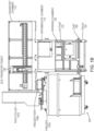
- Fig. 1B illustrates a front view of the system 100.
- the transfer module 101 includes three chambers: a transport chamber 110, an intermediate chamber 115, and a working chamber 120.
- the chambers 110, 115, 120 may be coupled to one another in series, and passage between the chambers may be selectively enabled via automated doors (not shown).
- the transport chamber 110 in both Figs. 1A and 1B , is shown in a cutaway view to illustrate components internal to the chamber 110, including a box transport robot 130.
- the transport chamber 110 may be closed as shown in Fig. 1E , which may contribute to preserving the temperature of the samples below a glass transition temperature.
- the box transport robot 130 operates to transport sample boxes between the freezer 105a, the I/O port 125, the working chamber 120, which it accesses by passing through the intermediate chamber 115, and additional locations.
- a freezer port 108a facilitates the transfer of sample boxes between the freezer 105a and the transfer module 101.
- the rack puller 107a after raising a storage rack from the freezer 105a, may propel the sample box into the freezer port 108a.
- the freezer port 108a may position the sample box for pickup by the box transport module 130.
- the freezer port 108a may propel the sample box toward the rack puller 107a, where it is added to a rack before the rack puller 107a lowers the rack into the freezer 105a.
- the freezer port 108a may be mounted to the freezer 105b and couples to the transport chamber 110 when the transfer module 101 is positioned to access the freezer 105a.
- the transport chamber 110 may include a port (e.g., an aperture) for connecting to the freezer port 108a, or may include a component of the freezer port 108a.
- the freezer port 108a may be mounted to the transport chamber 110, and aligns with the rack puller 107a when the transfer module 101 is positioned to access the freezer 105a.
- the working chamber 120 maintains a cryogenic environment, and enables the selection and transfer of individual sample tubes between sample boxes.
- the intermediate chamber 115 and transport chamber 110 may maintain temperatures and humidity above that of a cryogenic environment.
- the transport chamber 110 may be configured absent active temperature or humidity control, and, thus, may maintain a temperature comparable to room temperature.
- the intermediate chamber 115 may be configured similarly. However, both chambers 110, 115 may be cooled and/or dehumidified via convection from the cryogenic environment of the working chamber 120 and/or other cooling and/or dehumidifying methods..
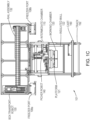
- Fig. 1C shows a cross-section view of the transport module 101.
- a second freezer port is shown 108b for servicing a freezer on an opposite side of the module 101 from the freezer 105a.
- the working chamber 120 is configured to maintain a cryogenic environment, thereby preserving the temperature of the samples within it below a respective glass transition temperature T G of the samples (e.g., -134C).
- an insulated wall 122 encompasses the bottom and sides of the chamber 120, and the top of the chamber 120 may be substantially isolated from the intermediate chamber 115 (e.g., via a removable cover or door) when sample boxes are not being transferred into or out of the working chamber 120.
- the working chamber 120 houses a platform 121 that supports multiple sample boxes and configurations, which are moved into and out of the working chamber 120 by the box transport robot 130.
- the intermediate chamber 115 houses operational machinery as described in further detail below, including the picker robot 140.
- the picker robot 140 operates to transfer individual sample tubes between sample boxes within the working chamber 120.
- the picker robot 140 substantially resides in the intermediate chamber 115, extending partially into the working chamber 120 during a sample transfer operation. As a result, the picker robot 140 may avoid adverse effects of exposure to the cryogenic environment of the working chamber 120.
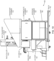
- Fig. 1D illustrates a side view of the system 100.
- an I/O shield 126 is shown more clearly.
- the I/O shield 126 may be coupled to one or both of the I/O port 125 and the transport chamber 110, and serves as a passageway between them.
- the I/O shield 126 therefore may protect the sample box and robot 130 from interference.
- the I/O shield 126 may also include a removable cover or door at the threshold of the transport chamber 110 to reduce gas transfer between the transport chamber 110 and the external environment.
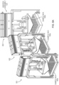
- Fig. 1E illustrates the transfer module 101 in a further view.
- the transport chamber 110 is shown with its enclosure intact, and a fill station 194 may be located at the front, rear or side of the module 101, and is described in further detail below with reference to Figs. 1G-I .
- the fill station 194 may connect to a liquid coolant source, and directs a liquid coolant (e.g., a cryogenic fluid such as liquid nitrogen) to the working chamber 120 where it cools the working chamber to a cryogenic temperature.
- a liquid coolant e.g., a cryogenic fluid such as liquid nitrogen
- Fig. 1F illustrates an example storage rack 185 and sample boxes 180a-b that may be implemented in the system 100.
- the system 100 may be configured to store and transfer sample boxes of multiple different formats.
- sample boxes 180a and 180b shown in top-down view, correspond to a Society for Biomolecular Screening (SBS) standard format box and a Cryobox standard format box, respectively.
- SBS Society for Biomolecular Screening
- Each sample box 180a-b includes multiples slots for storing samples, such as sample tubes 182a-b.
- the storage rack 185 includes multiple rack slots (e.g., rack slot 186) for storing respective sample boxes.
- the freezer 105a may store multiple storage racks resembling the storage rack 185, and the rack puller 107a may raise the storage rack 185 from the freezer 105a by engaging with an interface 188 mounted to the top of the storage rack 188.
- the rack slot 186 may be adapted to accommodate the largest box format (e.g., sample box 180b, Cryobox), and may optionally include a stopper 187 positioned to accommodate a smaller box format (e.g., sample box 180a, SBS).
- the stopper 187 may prevent the sample box 180a from moving to the rear of the storage rack 185, thereby maintaining a face of the sample box 180a at a front face of the storage rack 187.
- the stopper 187 may be omitted from slots accommodating the larger box format, or may be shaped to allow passage by the larger box format.
- the storage rack 185 can store and present the sample boxes 180a-b in a uniform manner.
- the storage rack 187 may be adapted to accept a single, uniform box format and orientation.
- Figs. 1G-1I illustrate the fill station 194 in further detail.
- Fig. 1G is a perspective view of the fill station 194.
- a receiver 196 may extend from the transfer module 101 to receive a liquid coolant for cooling the working chamber 120, and is covered by a receiver cap 197.
- a nozzle assembly 191 may extend from a liquid coolant source, and may be integrated into a wall proximate to the receiver 196 when the transfer module 101 is at a particular location.
- a controller e.g., controller 195 described below
- the controller may control a valve or other component controlling flow at the nozzle assembly 191, and may be integral to the wall and/or an access panel (e.g., access panel 1510 described below).
- the nozzle assembly 191 may descend onto the receiver 196.
- the nozzle assembly includes an extension 193 projecting downward such that, during the descent, the extension 193 may contact the receiver cap 197 and cause the receiver cap 197 to swing open and to the side, exposing the top of the receiver 196 as shown in the side view in Fig. 1H .
- the nozzle assembly 191 may continue to descend until it is coupled with the receiver 196, as shown in the cross-section view of Fig. 1I . Once coupled, the nozzle assembly 191 may transfer the liquid coolant to the receiver 196 as indicated by the arrow in Fig. 1I .
- Fig. 2 is a block diagram of the cryogenic storage system 100 configured with a controller 195 in a further embodiment.
- the system 100 includes a second freezer 105b, which can be selectively coupled to the transfer module 101 via the freezer port 108b.
- the controller 195 may be connectively coupled to the transfer module 101 and the freezers 105a-b, and may generally control some or all of the operations of each.
- the controller 195 may control the freezers 105a-b and respective rack pullers 107a-b to retrieve and replace selected sample boxes (e.g., sample boxes 180a-b) to and from the freezers 105a-b.
- the controller 195 may also control the transfer module 101 to transport sample boxes between the freezer ports 108a-b, the I/O port 125, and the working chamber 120, and to transfer sample tubes between sample boxes in the working chamber 120. Further, the controller 195 may monitor and control refrigeration and humidity levels of the transfer module 101 (particularly the working chamber 120) and the freezers 105a-b, and may control other operations such as calibration of mechanical components, identifying samples, and failure or disaster recovery.
- the controller 195 may also maintain a database 198 storing information regarding the samples stored within the working chamber 120 and freezers 105a-b, including the location of each sample within the freezers 105a-b. The controller 195 may update the database 198 in response to the transfer of samples into or out of the freezers 105a-b.
- the controller 195 may include suitable computer hardware and software resources, such as one or more computer workstations and an interface configured for communication with the transfer module 101 and freezers 105a-b.
- the controller 195 may also include an interface (e.g., a workstation) allowing a user to monitor the system 100 as well as monitor and/or control the aforementioned operations of the system 100.
- Fig. 3 is a flow diagram illustrating a process 300 of transferring samples, which may be carried out by the system 100 described above with reference to Figs. 1A-E and 2 .
- the controller 195 may parse a transfer order, which specifies one or more sample tubes (e.g., sample tubes 182a-b) and/or sample boxes (e.g., sample boxes 180a-b) to be transferred (305).
- the transfer order may specify one or more of an origin, a destination, and one or more sample identifiers (IDs) that identify a sample box 180a and/or sample tubes.
- IDs sample identifiers
- a transfer order may specify:
- the controller may determine the origin and destination of the samples to be transferred (310). To do so, the controller 195 may refer to the database 198 to determine the present location of the samples, and/or may cause the transfer module 101 to perform a scan of the samples (e.g., via an ID reader) to determine the respective sample IDs. With this information, the controller 195 may then map a route to be taken by the box transfer robot 130 to carry out the transfer (315). If the transfer requires a transfer in individual sample tubes between sample boxes, then the controller 195 may command the box transport robot 130 to transport one or more sample boxes to the working chamber 120 (320).
- the controller 195 may command the box transport robot 130 to 1) pick up a sample box 180a at the freezer port 108a and transport it to a selected support surface in the working chamber 120, and 2) pick up a second sample box at the I/O port 125 and transport it to another selected support surface in the working chamber 120.
- the controller 195 may also command the freezers 105a-b and rack pullers 107a-b to retrieve and produce the sample boxes at the respective freezer ports 108a-b.
- the controller 195 may then command the box transport robot 130 to transport the sample boxes from the working chamber 120 toward their destination(s) (e.g., the freezer ports 108a-b, the I/O port 125) (335).
- the controller 195 may also command the freezers 105a-b and rack pullers 107a-b to accept sample boxes deposited to the freezer ports 108a-b, place those boxes into a designated slot 186 in a storage rack 185, and return the storage rack 185 to the respective freezer 105a-b.
- the controller 195 may then update the database 198, based on the transfer, to indicate the updated location of each of the samples and/or sample boxes involved in the transfer.
- the controller 195 may command the box transport robot 130 to transport the samples boxes directly from their origin to their destination, without first locating to the working chamber 120. In such a transfer, the operations 320-335 may be omitted.
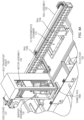
- Fig. 4A-B illustrate the box transport robot 130 in further detail.
- Fig. 4A is a perspective view of the box transport robot 130 within the transport chamber 110.
- the box transport robot 130 is mounted to an automated rail assembly 132, which provides for lateral movement of the robot 130 along the rails 133a-b of the assembly 132.
- the box transport robot 130 may move in the x direction along the rail 133a, and along the y direction along the rail 133b, enabling the box transport robot 130 to move to locations above the I/O port 125 and the intermediate chamber 115.
- the box transport robot 130 may be housed within an enclosure 131 (e.g., a windowed enclosure as shown), and includes a vertical driver 134 and a gripper assembly 135.
- Fig. 4B is a front cross-section of the box transport robot 130.
- the gripper assembly 135 is engaged with the sample box 180b and has raised the sample box 180b into the enclosure 131.
- the sample box 180b may be protected during transport within the transfer module 101, and the enclosure 131 may also function as a heat shield and convection blocker to reduce the heat absorbed by the sample box 180a-b during transport.
- Figs. 5A-B illustrate the gripper assembly 135 in further detail.
- Fig. 5A is a perspective view
- Fig. 5B is a front view.
- the gripper assembly 135 includes a pair of gripper arms 138a-b that can selectively engage and secure a sample box, such as the sample box 180a as shown, by closing toward the center of the sample box 180a and contacting opposite corners of the sample box 180a.
- the gripper assembly 135 may implement one or more additional arms, which may be configured to secure additional corners and/or edges of the sample box 180a.
- a cover 137 can be selectively lowered onto a top surface of the sample box 180a once secured by the gripper arms 138a-b.
- the cover 137 may secure the sample tubes within the sample box 180a-b, and may also serve as a heat shield and minimize frost buildup at the sample tubes.
- a motor assembly 136 controls operation of the gripper arms 138a-b and cover 137, and may include a motor configured to drive the gripper arms 138a-b inward toward the center of the gripper assembly 135, as well as outward from the center when reversed.
- the motor assembly 136 may be replaced by a gear assembly that is controlled by a motor set coupled to the gear assembly and located farther from the gripper arms 138a-b.
- the motors operating the gripper assembly 135 can be further isolated from the working chamber 120, thereby minimizing adverse effects of the cryogenic environment on the motors.
- Figs. 6A-C illustrate the gripper assembly configured to secure a range of different sample box formats and orientations.
- Fig. 6A is a perspective view of the gripper assembly 135 gripping sample boxes in three different configurations 601, 602, 603.
- the gripper assembly 135 is configured to engage with the sample box 180a (e.g., a rectangular SBS format box).
- the gripper assembly 135 is configured to engage with the same sample box 180a, but oriented 90° from the first orientation.
- the gripper assembly 135 is configured to engage with the sample box 180b (e.g., a square Cryobox format box).
- the gripper assembly 135 may rotate to a position such that its gripper arms 138a-b are both at opposite corners of the sample box and are aligned such that each of gripper arms 138a-b can apply a force toward the center of the sample box. As a result of such positioning, the gripper arms 138a-b may close in to secure the respective sample box.
- the pair of gripper arms 138a-b may also operate to adjust the sample box to a target rotational and positional orientation.
- the gripper assembly 135 may rotate to adjust between the grip positions for different box formats (e.g., SBS and Cryobox), allow the pickup of different orientations of a sample box (e.g., two orientations of an SBS format box), and rotate to allow the barcode reader to read any or all sides of the sample box.
- box formats e.g., SBS and Cryobox
- orientations of a sample box e.g., two orientations of an SBS format box
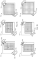
- Fig. 6B and Fig. 6C illustrate the configurations 601-603 in top-down and bottom-up views, respectively.
- the gripper arms 138a-b are shown to include respective contact members 139a-b.
- Each of the contact members 139a-b may form a pair of arms extending perpendicular to one another, where each arm includes a contact point (e.g., a pin) extending vertically from the arm.
- the gripper arms 138a-b may be rotated into position as described above, and then closed in toward the center of the sample boxes 180a-b.
- the contact members 139a-b make contact with two adjoining edges of the sample box 180a-b via the set of contact points, and each gripper arm 138a-b may apply a force toward the center of the sample boxes 180a-b sufficient to secure the sample boxes 180a-b within the gripper arms 138a-b.
- the contact member 139a-b may also extend partially underneath the sample boxes 180a-b when contact is made, thereby supporting the sample box 180a-b from below to further secure the sample boxes 180a-b during transport.
- Figs. 7A-B illustrate an example of the gripper assembly 135, wherein the gripper arms 138a-b each include a W-shaped contact member 139c-d in place of the contact members 139a-b described above.
- Each W-shaped contact member 139c-d may include two (or more) square notches, where each notch is adapted to secure a corner of a sample box in one or more particular formats or orientations.
- Three configurations 701, 702, 703 may be comparable to the configurations 601-603 described above.
- the gripper assembly 135 aligns the gripper arms 138a-b to the corners of the sample boxes 180a-b to one of the notches of the contact members 139c-d before closing in to secure the sample boxes 180a-b.
- the rightmost notch of contact member 139c and the leftmost notch of contact member 139d are aligned to contact opposite corners of the sample box 180a.
- the leftmost notch of contact member 139c and the rightmost notch of contact member 139d are aligned to contact opposite corners of the sample box 180a in an orientation rotated 90 degrees.
- the contact members 139c-d may include a lip 730 extending below the sample boxes 180a-b when secured.
- Figs. 8A-D illustrate the freezer port 108a in further detail.
- Fig. 8A is a perspective view of the freezer port 108a, which may connect with the rack puller 107a and provide for loading and unloading a sample box (e.g., sample box 180a as shown) to and from a storage rack (e.g., storage rack 185) loaded into the rack puller 107a.
- the freezer port 108a may also be referred to as an ejector, and includes a pair of pushers 830a-b.
- the pair of pushers 830a-b may push opposite sides of the sample box 108a to keep the sample box 108a secure while moving it along a guided passageway to a platform 820.
- the pusher 830a may be located partially at the rack puller 107a, and may extend from the rack puller 107a into the freezer port 108a.
- the sample box 180a may be picked up by the box transport robot 130, via the gripper arms 138a-b, for transport.
- the pushers 830a-b may push the sample box 180a from the platform 820, along the guided passageway, to the rack puller 107a. As the sample box 180a is pushed, both pushers 830a-b may maintain contact with the sample box 180a for box stability.
- Figs. 8B and 8C illustrate the freezer port 108a in operation of handling sample boxes in further orientations and formats.
- Fig. 8B shows freezer port 108a with the sample box 180a in an orientation turned 90° from the orientation shown in Fig. 8A .
- Fig. 8C shows the freezer port 108a with the sample box 180b.
- Fig. 8D illustrates the platform 820 in further detail.
- the box transport robot 130 may position a portion of the gripper arms 138a-b partially under the sample box as described above.
- the platform 820 may include depressible segments 822a-b.
- the depressible segments 822a-b may be supported by respective springs such that they support a sample box, but can be lowered by a downward force applied by the gripper arms 138a-b.
- Fig. 9 illustrates an automation station 900 in one example.
- the automation station 900 may be located at a floor 915 occupying a bottom interior surface of the intermediate chamber 115, and is positioned above the working chamber 120.
- the floor 915 enables passage to the working chamber 120 via an aperture 926, which may be selectively opened and closed via automated doors 925a-b.
- the doors 925a-b may remain closed outside of a transfer operation or sample access (e.g., picking, consolidating or tube identification operations), thereby minimizing heat transfer to the working chamber 120 and maintaining the cryogenic environment within it.
- An ID reader 930 may include one or more scanners (e.g., a barcode reader, a QR code scanner) configured to read a sample ID from a sample tube presented to it.
- the picker robot 140 may include a number of components occupying the automation station 900.
- the picker robot 140 may include a tube picker 142 that is mounted to an automated rail assembly 141, which provides for lateral and vertical movement of the tube picker 142.
- the rail assembly 141 may include three rail subassemblies 952, 953, 954, where each of the subassemblies controls movement of the tube picker 142 in a respective x, y and z direction.
- the tube picker 142 may be mounted to a vertical rail subassembly 952 for moving the picker robot in the z direction.
- the vertical rail subassembly 952 may be mounted to a first lateral rail subassembly 953 for movement in the x direction.
- the first lateral rail subassembly 953 may be mounted to a second lateral rail subassembly 954 for movement in the y direction.
- the tube picker 142 may be mounted to a robot arm or other automated mechanism for controlling the movement of the tube picker 142.
- Figs. 10A-B illustrate an I/O module 950.
- Fig. 10A is a perspective view, while Fig. 10B is a front view.
- the I/O module 950 may reside within the I/O port 125 ( Fig. 1A ), and is configured to scan a received sample box to determine a format and/or orientation of the box.
- a user may place the sample box on a movable stage 960 as it moves along a rail 962 to pass through a light curtain 965.
- the light curtain 965 may include a light source 966, a lens 967, and light sensors 968.
- the light source 967 may be a single light source that is collimated by the lens 967 (e.g.
- a Fresnel lens to project a collimated light beam across the rail 962 where it may be detected by the sensors 968 (e.g., a set of light sensors arranged in a vertical series).
- the sensors 968 e.g., a set of light sensors arranged in a vertical series.
- the beam of light may also be oriented diagonally to the path of the sample box as shown in Fig. 10A , thereby positioning the light curtain 965 to measure a diagonal length of the sample box as it passes through the light curtain 965.
- the signal detected by the sensors 968 can be interpreted to determine the height of the labware.
- the sensors 968 may detect a single sample tube raised above a height threshold for the labware type.
- the system may be alerted that a sample tube is seated improperly within a sample box, and can take corrective action to reposition the sample tube (e.g., returning the stage 960 to its starting position and alerting the user).
- a signal detected by the sensors 968 e.g., a voltage or current over time as a sample box is passed through the light curtain, or a digital signal
- the format and/or orientation of the sample box e.g., SBS or Cryobox format
- the module 101 may command the box transport robot 130 to configure its gripper arms 138a-b to properly engage with the sample box, and the box transport robot 130 may then pick up and transport the sample box from the I/O module 950 to the working chamber 120 or a freezer port 108a-b
- the I/O module may also include an ID reader (e.g., a barcode scanner) to read a sample ID of the sample box or sample tubes.
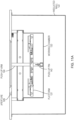
- Figs. 11A-C illustrate the working chamber 120 in further detail.
- Fig. 11A is a front cross-section of the working chamber 120.
- the working chamber 120 as described above, is configured to maintain a cryogenic environment, thereby preserving the temperature of the samples within it below a respective glass transition temperature T G of the samples (e.g., -134C).
- T G glass transition temperature
- an insulated wall 122 encompasses the bottom and sides of the chamber 120, and the top of the chamber 120 may be substantially isolated from the intermediate chamber 115 via the automated doors 925a-b that can cover the aperture 926 when sample boxes are not being transferred into or out of the working chamber 120 and when the samples are not being moved.
- the working chamber 120 houses a platform 121 that supports multiple sample boxes, which are moved into and out of the working chamber 120 by the box transport robot 130.
- the working chamber 120 may hold a volume of a liquid coolant (e.g., a cryogenic fluid such as liquid nitrogen) at a portion of the working chamber 120 below the platform 121.
- a push-up arm 144, terminating in a push-up pin 143, is an extension of the picker robot 140 (described in further detail below), and may be partially immersed in the liquid coolant.
- a portion of the push-up arm 144 may be composed of a material and structure to provide a low heat transfer, thereby reducing heat exchange between the liquid coolant and the environment external to the working chamber 120.
- the working chamber 120 may include a subchamber configured to contain the liquid coolant, or implement an alternative cooling mechanism (e.g., a heat exchanger) to maintain the cryogenic environment.
- Fig. 11B is a perspective view of components internal to the working chamber 120.
- the platform 121 is shown to include a set of support surfaces 127a-d for accepting and securing respective sample boxes. As shown, each of the support surfaces 127a-d is occupied by a sample box of a Cryobox format (e.g., sample box 180b). Clamps 128a-d may each apply a clamping force at a respective support surface 127a-d to secure the sample box in place. Further, heatsinks 123a-d may be coupled to outer edges or underside of the platform 121 and may extend vertically from the platform 121.
- the heatsinks 123a-d can assist in maintaining the cryogenic environment within the working chamber 120 and particularly the environment above the sample boxes, into which the sample tubes may be raised (by the picker robot 140) for transfer or scanning.
- the heatsinks 123a-d may also extend below the platform 121, and may be partially immersed in the liquid coolant occupying a volume below the platform 121.
- a brush 932 is described in further detail below with reference to Fig. 14A .
- Fig. 11C is a top-down view of the platform.
- support surfaces 127a-b are occupied by sample box in an SBS format (e.g., sample box 180a), while support surfaces 127c-d are occupied by sample boxes in a Cryobox format (e.g., sample box 180b).
- Sample boxes of either format can be supported at each of the support surfaces 127a-d.
- Each of the clamps 128a-d may terminate in 2 square notches as shown (e.g., a W shape comparable to the contact members 139c-d described above), where each notch is adapted to secure a corner of a sample box in one or more particular formats or orientations.
- clamps 128a-d apply a force toward a raised center guide(s) 129, they can make contact with a corner of a respective sample box at one of the notches, thereby securing the box regardless of format or orientation.
- the clamps 128a-d may be actuated by motors located external to the working chamber 120, which transfer a torque to a rack and pinion of the clamps 128a-d via respective rods 1115a-d.
- the platform 121 may define one or more apertures, such as aperture 124.
- the apertures may extend to some or all of the support surfaces 127a-d to expose at least a portion of the bottom surface of a sample box when occupying the support surfaces 127a-d.
- the picker robot 140 operating the push-up arm 144 ( Fig. 11A ) below the platform 121, can insert the push-up pin 143 through the sample box to raise a selected sample tube partially out of the sample box, thereby facilitating access to the sample tube.
- the support surfaces 127a-d may not include apertures that enable access to all sample tubes by the push-up pin 143, due to the need to adequately support the sample box at the platform 121.
- the box transport robot 130 may lift, rotate and replace the sample box to its support surface 127a-d, or may move the sample box to another support surface 127a-d to expose a different portion of the bottom of the sample box to the push-up pin 143.
- Figs. 12A-G illustrate a tube picker 142 in further detail.
- the tube picker may be mounted to the rail assemblies 952-954, described above with reference to Fig. 9 , for movement in the x, y and z directions.
- Fig. 12A is a perspective view of the tube picker 142 including a frost shield 1210. Because the tube picker 142, and particularly the lower portion of the tube picker 142, is periodically lowered into the cryogenic environment of the working chamber 120, it is susceptible to a buildup of frost.
- the frost shield 1210 covers the lower portion of the tube picker 142 to minimize the buildup of frost on the components housed within.
- Fig. 12B is a perspective view of the tube picker 142 absent the frost shield 1210.
- a motor 1220 operates to actuate a gripper head 1225 at an opposite end of the tube picker 142. Due to the cryogenic environment in which the gripper head 1225 operates, the motor 1220 (and other powered components) may be located remotely from the gripper head 1225 in order to prevent adverse effects on the motor 1220.
- a pair of support rods 1230a-b may extend between the motor 1220 and the gripper head 1225 to support the assembly.
- a shaft 1250 powered by the motor 1220, actuates the gripper head 1225.
- Figs. 12C and 12D show the gripper head 1225 in a perspective view and a cross-section, respectively.
- the shaft 1250 connects to a first gear 1252, which meshes with a second gear 1262 that rotates around a center pin 1260.
- the second gear 1262 is also coupled to a cam plate 1264, which is retained by a retainer 1266.
- Figs. 12E-G are cross-sections of a bottom-up view of the gripper head 1225, and are ordered to illustrate operation of the gripper head 1225.
- the first gear 1252 driven by the motor 1220, rotates the second gear 1262, which also rotates the cam plate 1264.
- pins 1272a-c coupled to teeth 1274a-c, move radially along respective tracks 1270a-c as the cam plate 1264 rotates.
- Fig. 12G shows in further detail the set of gripper teeth 1274a-c (also referred to as tube clamps), which engage with a sample tube (e.g., sample tube 182a).
- each of the teeth 1274a-c is pinned to a plate of the gripper head 1225, while an opposite end is coupled to a respective one of the pins 1272a-c.
- the teeth 1274a-c rotate at one end toward a center of the gripper head 1225 providing a horizontal gripping force, thereby making contact with a sample tube aligned at the gripper head 1225.
- the gripper head 1225 can be configured to support a variety of sample tube diameters (e.g., by advancing the teeth 1274 a given distance corresponding to a selected tube diameter) without the need for tool changes.
- the teeth 1274a-c may be thermally isolated (e.g., via an insulating material, such as a gap of air) from the components that bridge into the intermediate chamber, thereby reducing heat transfer to a gripped sample tube.
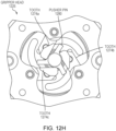
- Fig. 12H is a further bottom-up view of the gripper head 1225, illustrating the teeth 1274a-c in a fully engaged state.
- a pusher pin 1280 may occupy a center of the gripper head 1225 directly above the teeth 1274a-c.
- the pusher pin 1280 may be actuated by the motor 1220 (e.g., via the center pin 1260), and operates to separate a sample tube from the teeth 1274a-c when disengaging the sample tube.
- the pusher pin 1280 may be sized, as shown, to pass through the teeth 1274a-c even when fully engaged, and may include fins as shown to facilitate contact with the sample tube.
- the pusher pin 1280 can assist in placing and positioning a sample tube in a target slot of a sample box, and can also counteract binding between the teeth 1274a-c and the sample tube as a result of frost.
- Fig. 13 illustrates a portion of a tube picker robot 140 in an operation of extracting a sample tube 182b from a sample box 180b in the working chamber 120.
- the gripper head 1225 and push-up pin 143 may first be positioned directly above and below, respectively, the target sample tube 182b.
- the push-up arm 144 which may be driven by the rail assemblies 953, 954 ( Fig. 9 ) to move laterally in unison with the gripper head 1225, may then raise the push-up pin 143 up through the platform 121 and the sample box 180b, contacting and raising a top portion of the sample tube 182b above the other tubes in the sample box 180b.
- the gripper head 1225 has sufficient clearance to engage with the sample tube 182.
- the gripper head 1225 then grips the top of the sample tube 182b and lifts the sample tube 182b up and out of the sample box 180b.
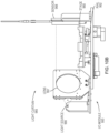
- Figs. 14A-B illustrate a portion of a tube picker robot 140 in an operation scanning a sample ID of a sample tube. The scanning may occur after the extraction operation described above with reference to Fig. 13 .
- Fig. 14A illustrates a scan of a sample ID located at the side of a sample tube 182b.
- the gripper head 1225 may raise the sample tube 182b partially (or fully) outside of the working chamber 120 and rotate the sample tube 182b to align a portion of the sample tube 182b with a line-of-sight (LOS) of the ID reader 930.
- LOS line-of-sight
- the gripper head 1225 may first move the sample tube 182b against a brush 932 located inside or outside the working chamber 120 to remove the frost.
- the ID reader 930 may include a plurality of different readers (e.g., a ID barcode reader, a 2D barcode reader) in order to scan a range of different sample ID formats. Further, the ID reader 930 may be implemented with one or more optical tools (e.g., mirrors, lenses) to facilitate visibility of the sample ID to the ID reader 930.
- one or more mirrors may be positioned to reflect an image of the sample ID at the sample tube to the ID reader 930 while the sample tube is located inside the working chamber 120, thereby allowing the sample tube 182b to be identified without exposing it to the non-cryogenic environment outside of the working chamber 120.
- the picker robot 140 may proceed to control the gripper head 1225 to transfer the sample tube 182 to a target slot in a destination sample box.
- Fig. 14B illustrates a scan of a sample ID in a further example.
- a sample ID is located at the bottom of the sample tube 182b.
- a mirror 931 may be positioned in or out of the working chamber 120 and below the ID reader 930 to provide the ID reader with a reflected bottom-up view of the sample tube 180b when raised above the working chamber 120.
- the gripper head 1225 may raise the sample tube 182b outside of the working chamber 120 to align the bottom of the sample tube with the reflected line-of-sight of the ID reader 930.
- the ID reader 930 can scan the sample ID at the bottom of the sample tube 182b.
- Fig. 15 is a perspective view of a system 1500 including multiple freezers.
- the system 1500 may include some or all of the features of the system 100 described above, including the transfer module 101 that is configured to move along the track 192.
- the transfer module is configured to service up to two rows each of multiple automated freezers 1505a-h, the rows being aligned at each side of the track 192.
- Each of the automated freezers 1505a-h may include features of the freezer 105a, the rack puller 107a and, optionally, the freezer port 108a described above.
- the transfer module 101 may move along the track 192 to align its freezer port with either the rack puller or freezer port of the selected freezer.
- the system 1500 may also include an access panel 1510 that includes a door 1520.
- I/O port e.g., I/O port 125
- the system 1500 as a whole may be encompassed by adjoining walls (e.g., implemented in a closed room) to ensure user safety during operation.
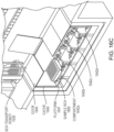
- Fig. 16A illustrates a system 1600 in a further example.
- the system 1600 may include some or all of the features of the system 100 described above, but in a configuration that maintains a working chamber as a stationary module, and maintains a transport chamber and an intermediate chamber, and a box transport robot and a picker robot.
- the transfer station 1650 may encompass some or all features of the working chamber 120, intermediate chamber 115, automation station 900, ID reader 930, and picker robot 130.
- the transport module 1601 may encompass some or all features of the transport chamber 110, box transport robot 130, rail assembly 132, I/O port 125, and I/O module 950 described above, and may further include a cache for temporarily storing sample boxes during a transport operation.
- the transport module 1601 may also include some or all features of the freezer port 108a described above.
- the transport module 1601 may move along a track 1692 to align with a selected automated freezer (e.g., freezer 1605a, which may include the features of the freezer 105a, rack puller 107a and freezer port 108a described above).
- the transport module 1601 obtains a sample box from the freezer 1605a and stores it to a cache.
- the transport module 1601 then moves along the track 1692 to align with the transfer station 1650, and transports the selected sample box (and, optionally, other sample boxes) into a working chamber of the transfer station 1650.
- the transfer station 1650 utilizing a picker robot, may perform a transfer of selected sample tubes between the selected sample box and one or more other sample boxes as described above.
- the transport module 1601 may retrieve the selected sample box and return it to the freezer 1605a, or may transport it to a different freezer, or to a user via an integrated or standalone I/O port.
- the transfer station may simplify maintenance of the cryogenic environment within it.
- the transport module 1601 by omitting some elements of the transfer module 101 described above, may occupy less space and mass than the transfer module 101, thereby simplifying movement and accommodating a compact arrangement of the components of system 1600.
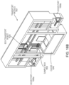
- Fig. 16B illustrates the transport module 1601 in further detail, with a front cover removed.
- the transport module 1601 may include a box transport robot 1630 that may include some or all features of the box transport robot 130 and rail assembly 132 described above.
- the box transport robot 1630 may operate to transport sample boxes (e.g., sample box 180b as shown) between doors (interfacing with the freezers 1605a-d) 1608a-b and a cache 1640.
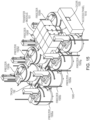
- Fig. 16C illustrates the box transport module 1601 and the cache 1640 in further detail.
- the cache 1640 may include some features of the working chamber 120 described above.
- the cache 1640 may include a platform 1641 that forms a plurality of support surfaces 1642a-d, each support surface being configured to support a respective sample box such as the sample box 180b as shown at the support surface 1642a.
- the cache 1640 may also maintain a cryogenic environment, and may do so by containing a volume of a liquid coolant (e.g., liquid nitrogen).
- the cache may be configured to maintain a temperature above a cryogenic temperature, provided that the samples can be maintained at an acceptable temperature (e.g., below a respective glass transition temperature) for the duration of their time stored at the cache 1640.
- An automated door 1645 provides passage to the cache 1640, and can be sealed outside of access by the box transport robot 1630 to maintain the environment of the cache 1640.
Landscapes
- Engineering & Computer Science (AREA)
- Life Sciences & Earth Sciences (AREA)
- Mechanical Engineering (AREA)
- Chemical & Material Sciences (AREA)
- General Health & Medical Sciences (AREA)
- Health & Medical Sciences (AREA)
- Physics & Mathematics (AREA)
- Dentistry (AREA)
- Wood Science & Technology (AREA)
- Zoology (AREA)
- Environmental Sciences (AREA)
- Combustion & Propulsion (AREA)
- Thermal Sciences (AREA)
- General Engineering & Computer Science (AREA)
- Analytical Chemistry (AREA)
- Biochemistry (AREA)
- General Physics & Mathematics (AREA)
- Immunology (AREA)
- Pathology (AREA)
- Robotics (AREA)
- Chemical Kinetics & Catalysis (AREA)
- Warehouses Or Storage Devices (AREA)
- Automatic Analysis And Handling Materials Therefor (AREA)
Description
- This application relates to a cryogenic storage system and to a method of transporting a sample in a cryogenic storage system.
- Cryopreservation is a process essential to maintaining the integrity of biological substances over extended periods of storage. At sufficiently low temperatures, all chemical processes and biological functions of such substances are effectively halted, allowing them to be stored safely over nearly any length of time. A cryogenic storage freezer enables such storage by providing an insulated and controlled cryogenic environment to accommodate a number of biological or other samples. In typical storage freezers, samples are loaded into racks or trays, each of which holds several samples. The racks or trays are manually removed from the cryogenic environment of the freezer, presenting the rack or tray to a user for removing samples from, or adding samples to, the storage freezer.
- Document
US9028754 WO 2012/033605 A2discloses a tube picking mechanism for use in an automated, ultra-low temperature (e.g. -80°C or -135°C) or cryogenic (e.g., about -140°C to - 196°C) storage and retrieval system that stores biological or chemical samples. The samples are contained in storage tubes held in SBS footprint storage racks that are normally stored within an ultra-low temperature or cryogenic freezer compartment. The tube picking mechanism includes a tube picking chamber that is maintained at about -80°C, about -135°C or at cryogenic temperatures in cryogenic applications. Further relevant prior art document isUS2016/288999 A1 . - The present invention provides a cryogenic storage system according to claim 1 and a method of transporting a sample in a cryogenic storage system according to claim 13. Optional or preferred features are defined in the respective dependent claims.
- The samples may be organized and tracked by scanning a barcode of each sample. Embodiments may also comprise multiple cryogenic storage freezers and provide for transfer of sample boxes and individual samples between the storage freezers, as well as between a storage freezer and an input/output (I/O) port accessible to a user.
- A cryogenic storage system according to claim 1 includes a transfer module configured to service one or more cryogenic storage freezers. The transfer module includes a working chamber that maintains a cryogenic environment for the transfer of sample tubes between different sample boxes. One or more freezer ports enable the transfer module to receive a sample box extracted from a respective freezer. An I/O port enables external access to samples. A box transport robot is configured to transport sample boxes between the freezer ports, the working chamber, the I/O port and other subsystems. A picker robot is configured to transfer sample tubes between sample boxes within the working chamber.
- The freezer port can include an ejector configured to transport the first sample box through at least a portion of the freezer port to a position accessible to the box transport robot. The ejector may include a pair of arms configured to clamp opposite sides of the first sample box. The ejector may also include a floor configured to support a sample box, where the floor includes one or more portions that are depressible via a force applied by the box transport robot. The ejector may also be configured to transport a plurality of different sample box formats.
- The transfer module includes a transport chamber, the transport chamber being coupled to the freezer port and housing the box transport robot. The box transport robot may maintain an environment above a glass transition temperature of the samples being transported through the chamber, and can be connected to the working chamber via an aperture. The transport chamber is connected to the working chamber via an intermediate chamber to the aperture, where the intermediate chamber houses at least a portion of the picker robot. The box transport robot is configured to extend into the working chamber, for example via the aperture during transport of a sample box. The picker robot is configured to extend into the working chamber, for example via the aperture during transport of a sample tube, such as transfer of the sample tube between sample boxes within the working chamber.
- The box transport robot may include a box gripper assembly configured to grip a sample box. The box gripper assembly may include a pair of arms configured to clamp opposing corners of the first sample box, where each arm includes a set of contact points adapted to accommodate a plurality of sample box formats. One or more of the sets of contact points may define a W shape, where a first portion of the W shape accommodates a first sample box format, and a second portion of the W shape accommodates a second sample box format. Alternatively, the contact points may terminate in a pair of pins, where the pins are oriented at a first angle to engage with a first sample box format, and are oriented at a second angle to accommodate a second box format. The box transport robot may also include a rail assembly on which the box gripper assembly moves.
- The picker robot may include a first arm including a tube gripper assembly and a second arm including a push-up pin. The second arm may extend under a platform supporting sample boxes in the working chamber, the second arm being configured to drive the push-up pin into the first sample box to raise a portion of the sample tube from a respective sample box. The tube gripper assembly may include a plurality of teeth, the tube gripper assembly configured to rotate the plurality of teeth around and toward a center axis to grip the sample tube. The teeth may also be used to prevent neighboring sample tubes from rising if frozen together. The first arm may be configured to move the sample tube to a position enabling an identification (ID) tag of the sample tube to be read by an ID reader. The position may be internal or external to the working chamber, and the first arm may rotate the sample tube to align the ID tag with the ID reader. The position may enable the ID tag to be read by the ID reader via a reflection of the ID tag from a mirror.
- The working chamber may include a platform configured to support multiple sample boxes during a transfer of sample tubes between them. A clamp assembly may be configured to secure a sample box via a force applied to a corner of the sample box, the clamp including a set of contact points adapted to accommodate a plurality of different sample box formats. The set of contact points may define a W shape, where a first portion of the W shape accommodates a first sample box format, and a second portion of the W shape accommodates a second sample box format. The platform may include an aperture exposing a portion of a bottom surface of a sample box, the aperture enabling access to a bottom of the sample tube by the tube picker robot. The working chamber may be further configured to contain a liquid coolant below the platform, as well as a heat sink coupled to the platform and configured to be partially immersed in the liquid coolant. The tube picker may include an arm supporting a push-up pin, the arm configured to be at least partially immersed in the liquid coolant.
- The transfer module may include a light curtain configured to detect a format of a sample box at the I/O port. The light curtain may project a single collimated light source.
- The transfer module may also include a plurality of freezer ports, each of the plurality of freezer ports being configured to receive sample boxes extracted from a respective freezer. A rail assembly may be configured to move the freezer ports between a plurality of freezers. The rail assembly may be further configured to move the working chamber, the box transport robot, and the tube picker robot in unison with the at least one freezer port. The freezer port may be configured to connect with an extractor assembly (e.g., an automated rack puller), the extractor assembly being configured to raise a storage rack from a freezer and eject the first sample box from the rack.
- A robot may comprise a box gripper assembly configured to grip a sample box. The box gripper assembly may include a pair of arms configured to clamp opposing corners of the sample box, as well as a pair of contact point sets coupled to a respective one of the pair of arms, each of the contact point sets configured to accommodate a plurality of sample box formats. The robot may further include a robotic transport mechanism configured to move the box gripper assembly. The first set of contact points may define a W shape, where a first portion of the W shape accommodates a first sample box format, and a second portion of the W shape accommodates a second sample box format. The robotic transport mechanism may include a rail assembly configured to move the box gripper assembly laterally and vertically. The robotic transport mechanism may include a robotic arm configured to move the box gripper assembly.
- A robot may be configured to pick and transfer sample tubes. The robot may include a first arm and a second arm. A tube gripper assembly may be coupled to the first arm and include a plurality of teeth, the tube gripper assembly configured to rotate the plurality of teeth around and toward a center axis to grip a sample tube. A push-up pin may be coupled to the second arm, the second arm being configured to drive the push-up pin into a sample box to raise a portion of the sample tube from the sample box prior to engagement by the tube gripper assembly. The robot may further include a motor configured to actuate the tube gripper assembly via an axle extending along the first arm.
- A platform, housed within the working chamber, may be configured to support a plurality of sample boxes. A box transport robot is configured to transport a first sample box into and out of the working chamber. A picker robot is configured to transport, within the working chamber, a sample tube between the first sample box and a second sample box. The working chamber may be further configured to contain a liquid coolant below the platform. A heat sink may be coupled to the platform and configured to be partially immersed in the liquid coolant.
The tube picker robot may include an arm supporting a push-up pin, the arm configured to be at least partially immersed in the liquid coolant. - The present invention is also disclosed in the method of transporting a sample in a cryogenic storage system according to the independent claim 13. Further embodiments are disclosed in dependent claims 14 and 15.
- Within the scope of method claim 14, removing the frost may include mechanically removing the frost. Reading the indicia may occur at least partially in the cryogenic environment. The indicia may be a barcode or at least one of an alphanumeric character, a graphic, and a symbol. Removing the frost may include moving the sample tube against a frost removal device using the picker robot. The frost removal device may be a brush or a blade. The frost removal may occur while the sample tube is fully within the cryogenic environment, and while a sample contained in the sample tube is kept below the glass transition temperature of the sample. Reading the indicia from the sample tube may occur while a sample contained in the sample tube is kept below the glass transition temperature of the sample. Reading the indicia from the sample tube may include reading the indicia with an optical device, such as a camera.
- Within the scope of method claim 15, when transporting a sample the sample may be removed from a first cryogenic environment. The sample may be placed into a second cryogenic environment wherein the second cryogenic environment is contained within a mobile apparatus. The sample may then be moved from a first sample receptacle to a second sample receptacle within the second cryogenic environment. The mobile apparatus may be automated. At least one of the removing the sample from the first cryogenic environment and the placing the sample into the second cryogenic environment may occur while the sample is kept below the glass transition temperature of the sample. The first and second cryogenic environments may be independently maintained.
- The foregoing will be apparent from the following more particular description of examples, as illustrated in the accompanying drawings in which like reference characters refer to the same parts throughout the different views. The drawings are not necessarily to scale, emphasis instead being placed upon illustrating examples.
-
Figs. 1A-I illustrate an automated cryogenic storage system and related components in an example -
Fig. 2 is a block diagram of a cryogenic storage system including a controller in a further example. -
Fig. 3 is a flow diagram illustrating a process of transferring individual samples in one example. -
Fig. 4A-B illustrate a box transport robot in one example. -
Figs. 5A-B illustrate a gripper assembly for a box picker robot. -
Figs. 6A-C illustrate the gripper assembly configured to grip a range of different box formats. -
Figs. 7A-B illustrate a box gripper in a further example. -
Figs. 8A-D illustrate a freezer port in one example. -
Fig. 9 illustrates an automation station in one example. -
Figs. 10A-B illustrate an I/O module in one example. -
Figs. 11A-C illustrate a working chamber in one example. -
Figs. 12A-H illustrate a tube picker in one example. -
Fig. 13 illustrates a tube extraction operation in one example. -
Fig. 14A-B illustrate a sample ID scan operation in one example. -
Fig. 15 illustrates a system implementing multiple freezers. -
Figs. 16A-C illustrates a system in a further example. - A description of examples follows.
-
Figs. 1A-F illustrate an automatedcryogenic storage system 100 and components in an example.Fig. 1A shows a perspective view of thesystem 100, which includes atransfer module 101, afreezer 105a, and arack puller 107a. Thefreezer 105a is a storage freezer that maintains a cryogenic environment for storing multiple samples, such as sample tubes assembled in sample boxes. In the illustrated examples, thefreezer 105a is a cylindrical vessel; however, the freezer can have any shape such as, for example, a rectangular box. In some examples,freezer 105a includes an external wall or shell separated from an inner wall or shell by a vacuum insulated space (e.g., a dewar vessel). Therack puller 107a may be mounted to the top of thefreezer 105a, and operates to raise a selected storage rack from thefreezer 105a. Once raised, a sample box can be added or removed from the rack, and therack puller 107a may then replace the rack into thefreezer 105a. Alternatively, therack puller 107a may be mounted to thetransfer module 101, and therack puller 107a may be selectively positioned to operate with thefreezer 105a as well as one or more other freezers (not shown). - The
transfer module 101 operates to transfer sample boxes, as well as individual sample tubes, between locations while maintaining those samples below a respective glass transition temperature TG (e.g., -134C), thereby maintaining the integrity of those samples. For example, themodule 101 may transfer sample boxes between thefreezer 105a, additional freezers (not shown), and an input/output (I/O)port 125, and may transfer sample tubes between those boxes. The I/O port 125 may be configured to accept a portable storage unit (not shown) storing one or more sample boxes, and a user may insert and remove the portable storage unit via an I/O door 199. - The
transfer module 101 may also relocate in order to service other freezers (not shown) in addition to thefreezer 105a. Acart 190 supports thetransfer module 101, and enables the module to move along atrack 192. Thecart 190 may be propelled automatically by a motor assembly in response to a movement command, or may be moved by a user. Thus, in further embodiments described below, wherein thetransfer module 101 services multiple freezers, thecart 190 and track 192 enables thetransfer module 101 to relocate to each of those multiple freezers. In further embodiments, a motion system for thetransfer module 101 may be configured above themodule 101 in addition to (or in place of) thecart 190 andtrack 192. Further, in place of thetrack 192, themodule 101 may be moved using a trackless motion system that uses a local positioning system (e.g., GPS, WiFi, optical (e.g. camera based), radar, lidar, floor or freezer mounted sensors). Propulsion can be provided to the transfer module by any known motion system, such as on-board motors that drive wheels or gears, in floor linear motors, off-board motors that drive cables or gears, or an overhead gantry system. -
Fig. 1B illustrates a front view of thesystem 100. Here, the disposition of thetransfer module 101 is shown in further detail. Thetransfer module 101 includes three chambers: atransport chamber 110, anintermediate chamber 115, and a workingchamber 120. Thechambers transport chamber 110, in bothFigs. 1A and1B , is shown in a cutaway view to illustrate components internal to thechamber 110, including abox transport robot 130. Thetransport chamber 110 may be closed as shown inFig. 1E , which may contribute to preserving the temperature of the samples below a glass transition temperature. Thebox transport robot 130 operates to transport sample boxes between thefreezer 105a, the I/O port 125, the workingchamber 120, which it accesses by passing through theintermediate chamber 115, and additional locations. Afreezer port 108a facilitates the transfer of sample boxes between thefreezer 105a and thetransfer module 101. In particular, therack puller 107a, after raising a storage rack from thefreezer 105a, may propel the sample box into thefreezer port 108a. Thefreezer port 108a, in turn, may position the sample box for pickup by thebox transport module 130. Conversely, when returning or storing a sample box to thefreezer 105a, thefreezer port 108a may propel the sample box toward therack puller 107a, where it is added to a rack before therack puller 107a lowers the rack into thefreezer 105a. Thefreezer port 108a may be mounted to thefreezer 105b and couples to thetransport chamber 110 when thetransfer module 101 is positioned to access thefreezer 105a. In such a configuration, thetransport chamber 110 may include a port (e.g., an aperture) for connecting to thefreezer port 108a, or may include a component of thefreezer port 108a. Alternatively, thefreezer port 108a may be mounted to thetransport chamber 110, and aligns with therack puller 107a when thetransfer module 101 is positioned to access thefreezer 105a. - The working
chamber 120 maintains a cryogenic environment, and enables the selection and transfer of individual sample tubes between sample boxes. In contrast, theintermediate chamber 115 andtransport chamber 110 may maintain temperatures and humidity above that of a cryogenic environment. For example, thetransport chamber 110 may be configured absent active temperature or humidity control, and, thus, may maintain a temperature comparable to room temperature. Theintermediate chamber 115 may be configured similarly. However, bothchambers chamber 120 and/or other cooling and/or dehumidifying methods.. -
Fig. 1C shows a cross-section view of thetransport module 101. Here, a second freezer port is shown 108b for servicing a freezer on an opposite side of themodule 101 from thefreezer 105a. The workingchamber 120, as indicated above, is configured to maintain a cryogenic environment, thereby preserving the temperature of the samples within it below a respective glass transition temperature TG of the samples (e.g., -134C). To facilitate this environment, aninsulated wall 122 encompasses the bottom and sides of thechamber 120, and the top of thechamber 120 may be substantially isolated from the intermediate chamber 115 (e.g., via a removable cover or door) when sample boxes are not being transferred into or out of the workingchamber 120. The workingchamber 120 houses aplatform 121 that supports multiple sample boxes and configurations, which are moved into and out of the workingchamber 120 by thebox transport robot 130. - The
intermediate chamber 115 houses operational machinery as described in further detail below, including thepicker robot 140. Thepicker robot 140 operates to transfer individual sample tubes between sample boxes within the workingchamber 120. Thepicker robot 140 substantially resides in theintermediate chamber 115, extending partially into the workingchamber 120 during a sample transfer operation. As a result, thepicker robot 140 may avoid adverse effects of exposure to the cryogenic environment of the workingchamber 120. -
Fig. 1D illustrates a side view of thesystem 100. Here, an I/O shield 126 is shown more clearly. The I/O shield 126 may be coupled to one or both of the I/O port 125 and thetransport chamber 110, and serves as a passageway between them. When thebox transport robot 130 adds or removes a sample box from the I/O port 125, it extends through the I/O shield 126. The I/O shield 126 therefore may protect the sample box androbot 130 from interference. The I/O shield 126 may also include a removable cover or door at the threshold of thetransport chamber 110 to reduce gas transfer between thetransport chamber 110 and the external environment. -
Fig. 1E illustrates thetransfer module 101 in a further view. Here, thetransport chamber 110 is shown with its enclosure intact, and afill station 194 may be located at the front, rear or side of themodule 101, and is described in further detail below with reference toFigs. 1G-I . Thefill station 194 may connect to a liquid coolant source, and directs a liquid coolant (e.g., a cryogenic fluid such as liquid nitrogen) to the workingchamber 120 where it cools the working chamber to a cryogenic temperature. -
Fig. 1F illustrates anexample storage rack 185 andsample boxes 180a-b that may be implemented in thesystem 100. Thesystem 100 may be configured to store and transfer sample boxes of multiple different formats. For example,sample boxes sample box 180a-b includes multiples slots for storing samples, such assample tubes 182a-b. - The
storage rack 185 includes multiple rack slots (e.g., rack slot 186) for storing respective sample boxes. Thefreezer 105a may store multiple storage racks resembling thestorage rack 185, and therack puller 107a may raise thestorage rack 185 from thefreezer 105a by engaging with aninterface 188 mounted to the top of thestorage rack 188. To accommodate storage of sample boxes in different formats, therack slot 186 may be adapted to accommodate the largest box format (e.g.,sample box 180b, Cryobox), and may optionally include a stopper 187 positioned to accommodate a smaller box format (e.g.,sample box 180a, SBS). The stopper 187 may prevent thesample box 180a from moving to the rear of thestorage rack 185, thereby maintaining a face of thesample box 180a at a front face of the storage rack 187. The stopper 187 may be omitted from slots accommodating the larger box format, or may be shaped to allow passage by the larger box format. As a result, thestorage rack 185 can store and present thesample boxes 180a-b in a uniform manner. Alternatively, to provide greater storage capacity and maximize use of space within a freezer, the storage rack 187 may be adapted to accept a single, uniform box format and orientation. -
Figs. 1G-1I illustrate thefill station 194 in further detail.Fig. 1G is a perspective view of thefill station 194. Areceiver 196 may extend from thetransfer module 101 to receive a liquid coolant for cooling the workingchamber 120, and is covered by areceiver cap 197. Anozzle assembly 191 may extend from a liquid coolant source, and may be integrated into a wall proximate to thereceiver 196 when thetransfer module 101 is at a particular location. A controller (e.g.,controller 195 described below) may control the flow of the coolant to the workingchamber 120 based on a detected temperature and/or other conditions at the workingchamber 120. The controller may control a valve or other component controlling flow at thenozzle assembly 191, and may be integral to the wall and/or an access panel (e.g.,access panel 1510 described below). - Prior to a transfer of liquid coolant, the
nozzle assembly 191 may descend onto thereceiver 196. The nozzle assembly includes anextension 193 projecting downward such that, during the descent, theextension 193 may contact thereceiver cap 197 and cause thereceiver cap 197 to swing open and to the side, exposing the top of thereceiver 196 as shown in the side view inFig. 1H . Thenozzle assembly 191 may continue to descend until it is coupled with thereceiver 196, as shown in the cross-section view ofFig. 1I . Once coupled, thenozzle assembly 191 may transfer the liquid coolant to thereceiver 196 as indicated by the arrow inFig. 1I . -
Fig. 2 is a block diagram of thecryogenic storage system 100 configured with acontroller 195 in a further embodiment. As shown, thesystem 100 includes asecond freezer 105b, which can be selectively coupled to thetransfer module 101 via thefreezer port 108b. Thecontroller 195 may be connectively coupled to thetransfer module 101 and thefreezers 105a-b, and may generally control some or all of the operations of each. For example, thecontroller 195 may control thefreezers 105a-b andrespective rack pullers 107a-b to retrieve and replace selected sample boxes (e.g.,sample boxes 180a-b) to and from thefreezers 105a-b. Thecontroller 195 may also control thetransfer module 101 to transport sample boxes between thefreezer ports 108a-b, the I/O port 125, and the workingchamber 120, and to transfer sample tubes between sample boxes in the workingchamber 120. Further, thecontroller 195 may monitor and control refrigeration and humidity levels of the transfer module 101 (particularly the working chamber 120) and thefreezers 105a-b, and may control other operations such as calibration of mechanical components, identifying samples, and failure or disaster recovery. Thecontroller 195 may also maintain adatabase 198 storing information regarding the samples stored within the workingchamber 120 andfreezers 105a-b, including the location of each sample within thefreezers 105a-b. Thecontroller 195 may update thedatabase 198 in response to the transfer of samples into or out of thefreezers 105a-b. - To provide such control operations, the
controller 195 may include suitable computer hardware and software resources, such as one or more computer workstations and an interface configured for communication with thetransfer module 101 andfreezers 105a-b. Thecontroller 195 may also include an interface (e.g., a workstation) allowing a user to monitor thesystem 100 as well as monitor and/or control the aforementioned operations of thesystem 100. -
Fig. 3 is a flow diagram illustrating aprocess 300 of transferring samples, which may be carried out by thesystem 100 described above with reference toFigs. 1A-E and2 . With reference toFig. 2 , thecontroller 195 may parse a transfer order, which specifies one or more sample tubes (e.g.,sample tubes 182a-b) and/or sample boxes (e.g.,sample boxes 180a-b) to be transferred (305). The transfer order may specify one or more of an origin, a destination, and one or more sample identifiers (IDs) that identify asample box 180a and/or sample tubes. For example, a transfer order may specify: - a) storage of a
sample box 180a at the I/O port 125 to a specified or unspecified freezer (e.g.,freezer 105a), - b) retrieval of a specified storage box or sample tube to the I/
O port 125, - c) transfer of a specified
sample box 180a to a specified freezer, - d) retrieval of a specified individual or set of sample tubes to the I/
O port 125, - e) transfer of specified sample tubes between sample boxes, or
- f) transfer of the contents of a specified freezer to another freezer or the I/
O port 125. - Based on the transfer order, the controller may determine the origin and destination of the samples to be transferred (310). To do so, the
controller 195 may refer to thedatabase 198 to determine the present location of the samples, and/or may cause thetransfer module 101 to perform a scan of the samples (e.g., via an ID reader) to determine the respective sample IDs. With this information, thecontroller 195 may then map a route to be taken by thebox transfer robot 130 to carry out the transfer (315). If the transfer requires a transfer in individual sample tubes between sample boxes, then thecontroller 195 may command thebox transport robot 130 to transport one or more sample boxes to the working chamber 120 (320). For example, thecontroller 195 may command thebox transport robot 130 to 1) pick up asample box 180a at thefreezer port 108a and transport it to a selected support surface in the workingchamber 120, and 2) pick up a second sample box at the I/O port 125 and transport it to another selected support surface in the workingchamber 120. Thecontroller 195 may also command thefreezers 105a-b andrack pullers 107a-b to retrieve and produce the sample boxes at therespective freezer ports 108a-b. - In order to transfer sample tubes between sample boxes, the
controller 195 may map a route to be taken by thepicker robot 140 within the working chamber 120 (325). In doing so, the controller may refer to thedatabase 198 to determine the location of each sample tube within the sample boxes, as well as available slots within the sample boxes. Thecontroller 195 then commands thepicker robot 140 to operate according to the mapped route to effect the transfer of the sample tubes between the sample boxes (330). Thepicker robot 140, when transferring each sample tube, may also route the sample tube to a brush to remove frost from the sample tube followed by an ID reader (located, e.g., in the intermediate chamber 115) to confirm the sample ID of the sample tube. Once the sample tubes are relocated to their target sample boxes, thecontroller 195 may then command thebox transport robot 130 to transport the sample boxes from the workingchamber 120 toward their destination(s) (e.g., thefreezer ports 108a-b, the I/O port 125) (335). Thecontroller 195 may also command thefreezers 105a-b andrack pullers 107a-b to accept sample boxes deposited to thefreezer ports 108a-b, place those boxes into a designatedslot 186 in astorage rack 185, and return thestorage rack 185 to therespective freezer 105a-b. Thecontroller 195 may then update thedatabase 198, based on the transfer, to indicate the updated location of each of the samples and/or sample boxes involved in the transfer. - Alternatively, if the
transfer order 305 does not require a transfer of sample tubes between sample boxes, then thecontroller 195 may command thebox transport robot 130 to transport the samples boxes directly from their origin to their destination, without first locating to the workingchamber 120. In such a transfer, the operations 320-335 may be omitted. -
Fig. 4A-B illustrate thebox transport robot 130 in further detail.Fig. 4A is a perspective view of thebox transport robot 130 within thetransport chamber 110. Thebox transport robot 130 is mounted to anautomated rail assembly 132, which provides for lateral movement of therobot 130 along therails 133a-b of theassembly 132. For example, thebox transport robot 130 may move in the x direction along therail 133a, and along the y direction along therail 133b, enabling thebox transport robot 130 to move to locations above the I/O port 125 and theintermediate chamber 115. Thebox transport robot 130 may be housed within an enclosure 131 (e.g., a windowed enclosure as shown), and includes avertical driver 134 and agripper assembly 135. Thevertical driver 134 may include one or more stepper or servo motors and is configured to raise and lower thegripper assembly 135 along a vertical track to a distance sufficient to reach thefreezer ports 108a-b, the I/O port 125, and the workingchamber 120. Alternatively, the vertical driver may include an extendable arm (e.g., a telescoping arm) capable of lowering the gripper assembly as described above. Thegripper assembly 135 is configured to engage with sample boxes such as thesample box 180b as shown, enabling the box transport robot to transport thesample box 180b. -
Fig. 4B is a front cross-section of thebox transport robot 130. Here, thegripper assembly 135 is engaged with thesample box 180b and has raised thesample box 180b into theenclosure 131. In doing so, thesample box 180b may be protected during transport within thetransfer module 101, and theenclosure 131 may also function as a heat shield and convection blocker to reduce the heat absorbed by thesample box 180a-b during transport. -
Figs. 5A-B illustrate thegripper assembly 135 in further detail.Fig. 5A is a perspective view, andFig. 5B is a front view. Thegripper assembly 135 includes a pair ofgripper arms 138a-b that can selectively engage and secure a sample box, such as thesample box 180a as shown, by closing toward the center of thesample box 180a and contacting opposite corners of thesample box 180a. In further examples, thegripper assembly 135 may implement one or more additional arms, which may be configured to secure additional corners and/or edges of thesample box 180a. Acover 137 can be selectively lowered onto a top surface of thesample box 180a once secured by thegripper arms 138a-b. When in close proximity to the top of thesample box 180a-b, thecover 137 may secure the sample tubes within thesample box 180a-b, and may also serve as a heat shield and minimize frost buildup at the sample tubes. Amotor assembly 136 controls operation of thegripper arms 138a-b and cover 137, and may include a motor configured to drive thegripper arms 138a-b inward toward the center of thegripper assembly 135, as well as outward from the center when reversed. Alternatively, themotor assembly 136 may be replaced by a gear assembly that is controlled by a motor set coupled to the gear assembly and located farther from thegripper arms 138a-b. As a result, the motors operating thegripper assembly 135 can be further isolated from the workingchamber 120, thereby minimizing adverse effects of the cryogenic environment on the motors. -
Figs. 6A-C illustrate the gripper assembly configured to secure a range of different sample box formats and orientations.Fig. 6A is a perspective view of thegripper assembly 135 gripping sample boxes in threedifferent configurations first configuration 601, thegripper assembly 135 is configured to engage with thesample box 180a (e.g., a rectangular SBS format box). In the second configuration, thegripper assembly 135 is configured to engage with thesame sample box 180a, but oriented 90° from the first orientation. In the third configuration, thegripper assembly 135 is configured to engage with thesample box 180b (e.g., a square Cryobox format box). In order to secure the respective sample box in each configuration (adjusted to a known rotational and positional orientation), thegripper assembly 135 may rotate to a position such that itsgripper arms 138a-b are both at opposite corners of the sample box and are aligned such that each ofgripper arms 138a-b can apply a force toward the center of the sample box. As a result of such positioning, thegripper arms 138a-b may close in to secure the respective sample box. The pair ofgripper arms 138a-b may also operate to adjust the sample box to a target rotational and positional orientation. Thus, thegripper assembly 135 may rotate to adjust between the grip positions for different box formats (e.g., SBS and Cryobox), allow the pickup of different orientations of a sample box (e.g., two orientations of an SBS format box), and rotate to allow the barcode reader to read any or all sides of the sample box. -
Fig. 6B and Fig. 6C illustrate the configurations 601-603 in top-down and bottom-up views, respectively. Here, in the top-down view ofFig. 6B , thegripper arms 138a-b are shown to includerespective contact members 139a-b. Each of thecontact members 139a-b may form a pair of arms extending perpendicular to one another, where each arm includes a contact point (e.g., a pin) extending vertically from the arm. When securing the sample boxes 801a-b, thegripper arms 138a-b may be rotated into position as described above, and then closed in toward the center of thesample boxes 180a-b. When thegripper arms 138a-b are fully closed in, thecontact members 139a-b make contact with two adjoining edges of thesample box 180a-b via the set of contact points, and eachgripper arm 138a-b may apply a force toward the center of thesample boxes 180a-b sufficient to secure thesample boxes 180a-b within thegripper arms 138a-b. As shown inFig. 6C , thecontact member 139a-b may also extend partially underneath thesample boxes 180a-b when contact is made, thereby supporting thesample box 180a-b from below to further secure thesample boxes 180a-b during transport. -
Figs. 7A-B illustrate an example of thegripper assembly 135, wherein thegripper arms 138a-b each include a W-shapedcontact member 139c-d in place of thecontact members 139a-b described above. Each W-shapedcontact member 139c-d may include two (or more) square notches, where each notch is adapted to secure a corner of a sample box in one or more particular formats or orientations. Threeconfigurations contact member 139c-d for contact with a givensample box 180a-b, thegripper assembly 135 aligns thegripper arms 138a-b to the corners of thesample boxes 180a-b to one of the notches of thecontact members 139c-d before closing in to secure thesample boxes 180a-b. For example, inconfiguration 701, the rightmost notch ofcontact member 139c and the leftmost notch ofcontact member 139d are aligned to contact opposite corners of thesample box 180a. In contrast, inconfiguration 702, the leftmost notch ofcontact member 139c and the rightmost notch ofcontact member 139d are aligned to contact opposite corners of thesample box 180a in an orientation rotated 90 degrees.. As shown inFig. 7B , thecontact members 139c-d may include a lip 730 extending below thesample boxes 180a-b when secured. -
Figs. 8A-D illustrate thefreezer port 108a in further detail.Fig. 8A is a perspective view of thefreezer port 108a, which may connect with therack puller 107a and provide for loading and unloading a sample box (e.g.,sample box 180a as shown) to and from a storage rack (e.g., storage rack 185) loaded into therack puller 107a. Thefreezer port 108a may also be referred to as an ejector, and includes a pair ofpushers 830a-b. When ejecting thesample box 180a from therack puller 107a, the pair ofpushers 830a-b may push opposite sides of thesample box 108a to keep thesample box 108a secure while moving it along a guided passageway to aplatform 820. Thepusher 830a may be located partially at therack puller 107a, and may extend from therack puller 107a into thefreezer port 108a. Once positioned properly at theplatform 820, thesample box 180a may be picked up by thebox transport robot 130, via thegripper arms 138a-b, for transport. When returning asample box 180a to therack puller 107a, thepushers 830a-b may push thesample box 180a from theplatform 820, along the guided passageway, to therack puller 107a. As thesample box 180a is pushed, bothpushers 830a-b may maintain contact with thesample box 180a for box stability. -
Figs. 8B and 8C illustrate thefreezer port 108a in operation of handling sample boxes in further orientations and formats.Fig. 8B showsfreezer port 108a with thesample box 180a in an orientation turned 90° from the orientation shown inFig. 8A .Fig. 8C shows thefreezer port 108a with thesample box 180b. By applyingpushers 830a-b at opposite sides of thesample boxes 180a-b, thefreezer port 108a can accommodate a range of different sample box formats and orientations. -
Fig. 8D illustrates theplatform 820 in further detail. When gripping a sample box, thebox transport robot 130 may position a portion of thegripper arms 138a-b partially under the sample box as described above. In order to accommodate this positioning, theplatform 820 may includedepressible segments 822a-b. Thedepressible segments 822a-b may be supported by respective springs such that they support a sample box, but can be lowered by a downward force applied by thegripper arms 138a-b. -
Fig. 9 illustrates anautomation station 900 in one example. Theautomation station 900 may be located at afloor 915 occupying a bottom interior surface of theintermediate chamber 115, and is positioned above the workingchamber 120. Thefloor 915 enables passage to the workingchamber 120 via anaperture 926, which may be selectively opened and closed viaautomated doors 925a-b. Thedoors 925a-b may remain closed outside of a transfer operation or sample access (e.g., picking, consolidating or tube identification operations), thereby minimizing heat transfer to the workingchamber 120 and maintaining the cryogenic environment within it. AnID reader 930 may include one or more scanners (e.g., a barcode reader, a QR code scanner) configured to read a sample ID from a sample tube presented to it. - The
picker robot 140 may include a number of components occupying theautomation station 900. Specifically, thepicker robot 140 may include atube picker 142 that is mounted to anautomated rail assembly 141, which provides for lateral and vertical movement of thetube picker 142. Therail assembly 141 may include threerail subassemblies tube picker 142 in a respective x, y and z direction. In particular, thetube picker 142 may be mounted to avertical rail subassembly 952 for moving the picker robot in the z direction. Thevertical rail subassembly 952, in turn, may be mounted to a firstlateral rail subassembly 953 for movement in the x direction. Lastly, the firstlateral rail subassembly 953 may be mounted to a secondlateral rail subassembly 954 for movement in the y direction. In other examples, thetube picker 142 may be mounted to a robot arm or other automated mechanism for controlling the movement of thetube picker 142. -
Figs. 10A-B illustrate an I/O module 950.Fig. 10A is a perspective view, whileFig. 10B is a front view. The I/O module 950 may reside within the I/O port 125 (Fig. 1A ), and is configured to scan a received sample box to determine a format and/or orientation of the box. When receiving a sample box at the I/O port 125, a user may place the sample box on amovable stage 960 as it moves along arail 962 to pass through alight curtain 965. Thelight curtain 965 may include alight source 966, alens 967, andlight sensors 968. Thelight source 967 may be a single light source that is collimated by the lens 967 (e.g. a Fresnel lens) to project a collimated light beam across therail 962 where it may be detected by the sensors 968 (e.g., a set of light sensors arranged in a vertical series). As a result of the light beam being collimated, an object blocking the beam may be detected and measured substantially accurately regardless of distance from thelight source 966. The beam of light may also be oriented diagonally to the path of the sample box as shown inFig. 10A , thereby positioning thelight curtain 965 to measure a diagonal length of the sample box as it passes through thelight curtain 965. - When the light beam is blocked by the passing sample box, the signal detected by the
sensors 968 can be interpreted to determine the height of the labware. For example, thesensors 968 may detect a single sample tube raised above a height threshold for the labware type. In response, the system may be alerted that a sample tube is seated improperly within a sample box, and can take corrective action to reposition the sample tube (e.g., returning thestage 960 to its starting position and alerting the user). A signal detected by the sensors 968 (e.g., a voltage or current over time as a sample box is passed through the light curtain, or a digital signal) may also be interpreted to determine the format and/or orientation of the sample box (e.g., SBS or Cryobox format). Based on the detected format and orientation, themodule 101 may command thebox transport robot 130 to configure itsgripper arms 138a-b to properly engage with the sample box, and thebox transport robot 130 may then pick up and transport the sample box from the I/O module 950 to the workingchamber 120 or afreezer port 108a-b In further examples, the I/O module may also include an ID reader (e.g., a barcode scanner) to read a sample ID of the sample box or sample tubes. -
Figs. 11A-C illustrate the workingchamber 120 in further detail.Fig. 11A is a front cross-section of the workingchamber 120. The workingchamber 120, as described above, is configured to maintain a cryogenic environment, thereby preserving the temperature of the samples within it below a respective glass transition temperature TG of the samples (e.g., -134C). To facilitate this environment, aninsulated wall 122 encompasses the bottom and sides of thechamber 120, and the top of thechamber 120 may be substantially isolated from theintermediate chamber 115 via theautomated doors 925a-b that can cover theaperture 926 when sample boxes are not being transferred into or out of the workingchamber 120 and when the samples are not being moved. The workingchamber 120 houses aplatform 121 that supports multiple sample boxes, which are moved into and out of the workingchamber 120 by thebox transport robot 130. The workingchamber 120 may hold a volume of a liquid coolant (e.g., a cryogenic fluid such as liquid nitrogen) at a portion of the workingchamber 120 below theplatform 121. A push-up arm 144, terminating in a push-up pin 143, is an extension of the picker robot 140 (described in further detail below), and may be partially immersed in the liquid coolant. In such a configuration, a portion of the push-up arm 144, particularly a vertical shaft portion extending out of the workingchamber 120, may be composed of a material and structure to provide a low heat transfer, thereby reducing heat exchange between the liquid coolant and the environment external to the workingchamber 120. Alternatively, the workingchamber 120 may include a subchamber configured to contain the liquid coolant, or implement an alternative cooling mechanism (e.g., a heat exchanger) to maintain the cryogenic environment. -
Fig. 11B is a perspective view of components internal to the workingchamber 120. Here, theplatform 121 is shown to include a set ofsupport surfaces 127a-d for accepting and securing respective sample boxes. As shown, each of the support surfaces 127a-d is occupied by a sample box of a Cryobox format (e.g.,sample box 180b). Clamps 128a-d may each apply a clamping force at arespective support surface 127a-d to secure the sample box in place. Further,heatsinks 123a-d may be coupled to outer edges or underside of theplatform 121 and may extend vertically from theplatform 121. Theheatsinks 123a-d can assist in maintaining the cryogenic environment within the workingchamber 120 and particularly the environment above the sample boxes, into which the sample tubes may be raised (by the picker robot 140) for transfer or scanning. Theheatsinks 123a-d may also extend below theplatform 121, and may be partially immersed in the liquid coolant occupying a volume below theplatform 121. A brush 932 is described in further detail below with reference toFig. 14A . -
Fig. 11C is a top-down view of the platform. In contrast toFig. 11B ,support surfaces 127a-b are occupied by sample box in an SBS format (e.g.,sample box 180a), while support surfaces 127c-d are occupied by sample boxes in a Cryobox format (e.g.,sample box 180b). Sample boxes of either format can be supported at each of the support surfaces 127a-d. Each of theclamps 128a-d may terminate in 2 square notches as shown (e.g., a W shape comparable to thecontact members 139c-d described above), where each notch is adapted to secure a corner of a sample box in one or more particular formats or orientations. Thus, when theclamps 128a-d apply a force toward a raised center guide(s) 129, they can make contact with a corner of a respective sample box at one of the notches, thereby securing the box regardless of format or orientation. Theclamps 128a-d may be actuated by motors located external to the workingchamber 120, which transfer a torque to a rack and pinion of theclamps 128a-d viarespective rods 1115a-d. - To enable access to individual sample tubes within the sample boxes, the
platform 121 may define one or more apertures, such asaperture 124. The apertures may extend to some or all of the support surfaces 127a-d to expose at least a portion of the bottom surface of a sample box when occupying the support surfaces 127a-d. As a result, thepicker robot 140, operating the push-up arm 144 (Fig. 11A ) below theplatform 121, can insert the push-up pin 143 through the sample box to raise a selected sample tube partially out of the sample box, thereby facilitating access to the sample tube. Some or all of the support surfaces 127a-d may not include apertures that enable access to all sample tubes by the push-up pin 143, due to the need to adequately support the sample box at theplatform 121. In such a case, thebox transport robot 130 may lift, rotate and replace the sample box to itssupport surface 127a-d, or may move the sample box to anothersupport surface 127a-d to expose a different portion of the bottom of the sample box to the push-up pin 143. -
Figs. 12A-G illustrate atube picker 142 in further detail. The tube picker may be mounted to the rail assemblies 952-954, described above with reference toFig. 9 , for movement in the x, y and z directions.Fig. 12A is a perspective view of thetube picker 142 including afrost shield 1210. Because thetube picker 142, and particularly the lower portion of thetube picker 142, is periodically lowered into the cryogenic environment of the workingchamber 120, it is susceptible to a buildup of frost. Thefrost shield 1210 covers the lower portion of thetube picker 142 to minimize the buildup of frost on the components housed within. -
Fig. 12B is a perspective view of thetube picker 142 absent thefrost shield 1210. Amotor 1220 operates to actuate agripper head 1225 at an opposite end of thetube picker 142. Due to the cryogenic environment in which thegripper head 1225 operates, the motor 1220 (and other powered components) may be located remotely from thegripper head 1225 in order to prevent adverse effects on themotor 1220. A pair ofsupport rods 1230a-b may extend between themotor 1220 and thegripper head 1225 to support the assembly. Ashaft 1250, powered by themotor 1220, actuates thegripper head 1225. -
Figs. 12C and 12D show thegripper head 1225 in a perspective view and a cross-section, respectively. Theshaft 1250 connects to afirst gear 1252, which meshes with asecond gear 1262 that rotates around acenter pin 1260. Thesecond gear 1262 is also coupled to acam plate 1264, which is retained by aretainer 1266. -
Figs. 12E-G are cross-sections of a bottom-up view of thegripper head 1225, and are ordered to illustrate operation of thegripper head 1225. AtFig. 12E , thefirst gear 1252, driven by themotor 1220, rotates thesecond gear 1262, which also rotates thecam plate 1264. As shown inFig. 12F , pins 1272a-c, coupled toteeth 1274a-c, move radially alongrespective tracks 1270a-c as thecam plate 1264 rotates.Fig. 12G shows in further detail the set ofgripper teeth 1274a-c (also referred to as tube clamps), which engage with a sample tube (e.g.,sample tube 182a). One end of each of theteeth 1274a-c is pinned to a plate of thegripper head 1225, while an opposite end is coupled to a respective one of thepins 1272a-c. Thus, as a result of thepins 1272a-c moving along therespective track 1270a-c, theteeth 1274a-c rotate at one end toward a center of thegripper head 1225 providing a horizontal gripping force, thereby making contact with a sample tube aligned at thegripper head 1225. Thegripper head 1225 can be configured to support a variety of sample tube diameters (e.g., by advancing theteeth 1274 a given distance corresponding to a selected tube diameter) without the need for tool changes. Further, theteeth 1274a-c may be thermally isolated (e.g., via an insulating material, such as a gap of air) from the components that bridge into the intermediate chamber, thereby reducing heat transfer to a gripped sample tube. -
Fig. 12H is a further bottom-up view of thegripper head 1225, illustrating theteeth 1274a-c in a fully engaged state. Apusher pin 1280 may occupy a center of thegripper head 1225 directly above theteeth 1274a-c. Thepusher pin 1280 may be actuated by the motor 1220 (e.g., via the center pin 1260), and operates to separate a sample tube from theteeth 1274a-c when disengaging the sample tube. Thepusher pin 1280 may be sized, as shown, to pass through theteeth 1274a-c even when fully engaged, and may include fins as shown to facilitate contact with the sample tube. Thepusher pin 1280 can assist in placing and positioning a sample tube in a target slot of a sample box, and can also counteract binding between theteeth 1274a-c and the sample tube as a result of frost. -
Fig. 13 illustrates a portion of atube picker robot 140 in an operation of extracting asample tube 182b from asample box 180b in the workingchamber 120. Thegripper head 1225 and push-up pin 143 may first be positioned directly above and below, respectively, thetarget sample tube 182b. The push-up arm 144, which may be driven by therail assemblies 953, 954 (Fig. 9 ) to move laterally in unison with thegripper head 1225, may then raise the push-up pin 143 up through theplatform 121 and thesample box 180b, contacting and raising a top portion of thesample tube 182b above the other tubes in thesample box 180b. As a result, thegripper head 1225 has sufficient clearance to engage with the sample tube 182. Thegripper head 1225 then grips the top of thesample tube 182b and lifts thesample tube 182b up and out of thesample box 180b. -
Figs. 14A-B illustrate a portion of atube picker robot 140 in an operation scanning a sample ID of a sample tube. The scanning may occur after the extraction operation described above with reference toFig. 13 .Fig. 14A illustrates a scan of a sample ID located at the side of asample tube 182b. Thegripper head 1225 may raise thesample tube 182b partially (or fully) outside of the workingchamber 120 and rotate thesample tube 182b to align a portion of thesample tube 182b with a line-of-sight (LOS) of theID reader 930. If thesample tube 182b has accumulated frost covering the sample ID at the side of the tube, then thegripper head 1225 may first move thesample tube 182b against a brush 932 located inside or outside the workingchamber 120 to remove the frost. TheID reader 930 may include a plurality of different readers (e.g., a ID barcode reader, a 2D barcode reader) in order to scan a range of different sample ID formats. Further, theID reader 930 may be implemented with one or more optical tools (e.g., mirrors, lenses) to facilitate visibility of the sample ID to theID reader 930. For example, one or more mirrors may be positioned to reflect an image of the sample ID at the sample tube to theID reader 930 while the sample tube is located inside the workingchamber 120, thereby allowing thesample tube 182b to be identified without exposing it to the non-cryogenic environment outside of the workingchamber 120. Following the ID scan, thepicker robot 140 may proceed to control thegripper head 1225 to transfer the sample tube 182 to a target slot in a destination sample box. -
Fig. 14B illustrates a scan of a sample ID in a further example. In this example, a sample ID is located at the bottom of thesample tube 182b. In order to read the sample ID, amirror 931 may be positioned in or out of the workingchamber 120 and below theID reader 930 to provide the ID reader with a reflected bottom-up view of thesample tube 180b when raised above the workingchamber 120. Thegripper head 1225 may raise thesample tube 182b outside of the workingchamber 120 to align the bottom of the sample tube with the reflected line-of-sight of theID reader 930. As a result, theID reader 930 can scan the sample ID at the bottom of thesample tube 182b. -
Fig. 15 is a perspective view of asystem 1500 including multiple freezers. Thesystem 1500 may include some or all of the features of thesystem 100 described above, including thetransfer module 101 that is configured to move along thetrack 192. In contrast, the transfer module is configured to service up to two rows each of multipleautomated freezers 1505a-h, the rows being aligned at each side of thetrack 192. Each of theautomated freezers 1505a-h may include features of thefreezer 105a, therack puller 107a and, optionally, thefreezer port 108a described above. To service a selected one of theautomated freezers 1505a-h, thetransfer module 101 may move along thetrack 192 to align its freezer port with either the rack puller or freezer port of the selected freezer. - The
system 1500 may also include anaccess panel 1510 that includes adoor 1520. When thetransfer module 101 is positioned at theaccess panel 1510, it I/O port (e.g., I/O port 125) may be aligned with thedoor 1520, thereby enabling a user to access the I/O port through thedoor 1520 to add or remove samples at the I/O port. Thesystem 1500 as a whole may be encompassed by adjoining walls (e.g., implemented in a closed room) to ensure user safety during operation. -
Fig. 16A illustrates asystem 1600 in a further example. Thesystem 1600 may include some or all of the features of thesystem 100 described above, but in a configuration that maintains a working chamber as a stationary module, and maintains a transport chamber and an intermediate chamber, and a box transport robot and a picker robot.. Thetransfer station 1650 may encompass some or all features of the workingchamber 120,intermediate chamber 115,automation station 900,ID reader 930, andpicker robot 130. Thetransport module 1601 may encompass some or all features of thetransport chamber 110,box transport robot 130,rail assembly 132, I/O port 125, and I/O module 950 described above, and may further include a cache for temporarily storing sample boxes during a transport operation. In further examples, thetransport module 1601 may also include some or all features of thefreezer port 108a described above. - In an example operation, the
transport module 1601 may move along atrack 1692 to align with a selected automated freezer (e.g.,freezer 1605a, which may include the features of thefreezer 105a,rack puller 107a andfreezer port 108a described above). Thetransport module 1601 obtains a sample box from thefreezer 1605a and stores it to a cache. Thetransport module 1601 then moves along thetrack 1692 to align with thetransfer station 1650, and transports the selected sample box (and, optionally, other sample boxes) into a working chamber of thetransfer station 1650. Thetransfer station 1650, utilizing a picker robot, may perform a transfer of selected sample tubes between the selected sample box and one or more other sample boxes as described above. Once the sample tube transfer is complete, thetransport module 1601 may retrieve the selected sample box and return it to thefreezer 1605a, or may transport it to a different freezer, or to a user via an integrated or standalone I/O port. - By maintaining a stationary working chamber, the transfer station may simplify maintenance of the cryogenic environment within it. In addition, the
transport module 1601, by omitting some elements of thetransfer module 101 described above, may occupy less space and mass than thetransfer module 101, thereby simplifying movement and accommodating a compact arrangement of the components ofsystem 1600. -
Fig. 16B illustrates thetransport module 1601 in further detail, with a front cover removed. Thetransport module 1601 may include abox transport robot 1630 that may include some or all features of thebox transport robot 130 andrail assembly 132 described above. Thebox transport robot 1630 may operate to transport sample boxes (e.g.,sample box 180b as shown) between doors (interfacing with thefreezers 1605a-d) 1608a-b and acache 1640. -
Fig. 16C illustrates thebox transport module 1601 and thecache 1640 in further detail. Thecache 1640 may include some features of the workingchamber 120 described above. For example, thecache 1640 may include aplatform 1641 that forms a plurality of support surfaces 1642a-d, each support surface being configured to support a respective sample box such as thesample box 180b as shown at the support surface 1642a. Thecache 1640 may also maintain a cryogenic environment, and may do so by containing a volume of a liquid coolant (e.g., liquid nitrogen). Alternatively, the cache may be configured to maintain a temperature above a cryogenic temperature, provided that the samples can be maintained at an acceptable temperature (e.g., below a respective glass transition temperature) for the duration of their time stored at thecache 1640. Anautomated door 1645 provides passage to thecache 1640, and can be sealed outside of access by thebox transport robot 1630 to maintain the environment of thecache 1640. - While examples have been particularly shown and described, it will be understood by those skilled in the art that the present invention disclose in the independent claims 1 and 13, wherein further embodiments are disclosed in the dependent claims.
Claims (15)
- A cryogenic storage system, comprising:at least one freezer port (108a) configured to receive a first sample box (180a) extracted from a respective freezer (105a);a working chamber (120) configured to maintain a cryogenic environment, wherein the working chamber is configured to enable the selection and transfer of individual sample tubes between sample boxes within the working chamber;an input/output (I/O) port (125) configured to enable external access to samples;a box transport robot (130) configured to transport the first sample box between the at least one freezer port, the working chamber, and the I/O port;a picker robot (140) configured to transport, within the working chamber, a sample tube (182a) between the first sample box (180a) and a second sample box (180b);a transport chamber (110), the transport chamber being coupled to the at least one freezer port during access by the box transport robot, the transport chamber housing the box transport robot; andan intermediate chamber (115) coupled between the transport chamber and the working chamber, the intermediate chamber housing at least a portion of the picker robot, the box transport robot being configured to transport the first sample box through the intermediate chamber to the working chamber.
- The system of claim 1, further comprising an ejector configured to transport the first sample box through at least a portion of the at least one freezer port to a position accessible to the box transport robot, optionally (A) wherein the ejector includes a pair of arms (830a-b) configured to move and guide opposite sides to control positioning of the first sample box; (B) wherein the ejector includes a floor (915) configured to support the first sample box, at least a portion of the floor being depressible via a force applied by the box transport robot; or (C) wherein the ejector is configured to transport a plurality of different sample box formats.
- The system of claim 1, (A) wherein the transport chamber is further configured to maintain an environment above a glass transition temperature of samples of the first sample box; or (B) wherein the transport chamber is connected to the working chamber via an aperture, optionally wherein the box transport robot is configured to extend into the working chamber via the aperture during transport of the first sample box or wherein the picker robot is configured to extend into the working chamber via the aperture during transport of the sample tube.
- The system of claim 1, wherein the box transport robot further includes a box gripper assembly (135) configured to grip the first sample box, optionally (A) wherein the box gripper assembly includes a pair of arms (138a-b) configured to clamp opposing corners of the first sample box, each of the pair of arms including a set of contact points (139c-d) adapted to accommodate a plurality of sample box formats, the pair of arms being further configured to adjust the first sample box to a target rotational and positional orientation, further optionally wherein at least one of the sets of contact points define a W shape, a first portion of the W shape accommodates a first sample box format, and a second portion of the W shape accommodates a second sample box format; or (B) wherein the box transport robot includes a rail assembly (141) on which the box gripper assembly moves.
- The system of claim 1, wherein the picker robot includes a first arm (142) including a tube gripper assembly (1225) and a second arm (144) including a push-up pin (143), optionally (A) wherein the second arm extends under a platform (121) supporting sample boxes in the working chamber, the second arm being configured to drive the push-up pin into the first sample box to raise a portion of the sample tube from the first sample box; (B) wherein the tube gripper assembly includes a plurality of teeth (1274a-c), the tube gripper assembly configured to rotate horizontally the plurality of teeth around and toward a center axis to grip the sample tube, further optionally wherein the teeth are thermally isolated from components of the picker robot external to the working chamber via a thermal insulator; or (C) wherein the first arm is configured to move the sample tube to a position enabling an identification (ID) tag of the sample tube to be read by an ID reader, further optionally (a) wherein the position is external to the working chamber; (b) wherein the first arm is further configured to 1) pass the sample tube along a cleaner to remove frost from the sample tube and 2) rotate the sample tube to align the ID tag with the ID reader; or (c) wherein the position enables the ID tag to be read by the ID reader via a reflection of the ID tag from a mirror.
- The system of claim 1, wherein the working chamber includes a platform (121) configured to support the first and second sample boxes.
- The system of claim 6, further comprising a clamp assembly (128a-d) configured to secure the first sample box via a force applied to a corner of the first sample box, the clamp including a set of contact points adapted to accommodate a plurality of sample box formats, optionally wherein the set of contact points define a W shape, a first portion of the W shape accommodates a first sample box format, and a second portion of the W shape accommodates a second sample box format.
- The system of claim 6, wherein the platform includes an aperture (124) exposing a portion of a bottom surface of the first sample box, the aperture enabling access to a bottom of the sample tube by the tube picker robot, optionally wherein the working chamber is further configured to contain a liquid coolant below the platform, further optionally wherein the system further comprises a heat sink coupled to the platform and configured to be partially immersed in the liquid coolant or wherein the tube picker robot includes an arm (144) supporting a push-up pin (143), the arm configured to be at least partially immersed in the liquid coolant.
- The system of claim 1, further including a light curtain (965) configured to detect a format of a third sample box at the I/O port, optionally wherein the light curtain projects a single collimated light source.
- The system of claim 1, wherein the at least one freezer port includes a plurality of freezer ports (108a-b), each of the plurality of freezer ports being configured to receive sample boxes extracted from a respective freezer.
- The system of claim 1, further comprising a rail assembly (192) configured to move the at least one freezer port between a plurality of freezers, optionally wherein the rail assembly is further configured to move the working chamber, the box transport robot, and the tube picker robot in unison with the at least one freezer port.
- The system of claim 1, wherein the at least one freezer port is configured to connect with an extractor assembly (107a), the extractor assembly being configured to raise a storage rack from a freezer and eject the first sample box from the rack.
- A method of transporting a sample in a cryogenic storage system according to claim 1, comprising:extracting a first sample box (180a) from a respective freezer (105a) via a freezer port (108a);transporting the first sample box, via a box transport robot (130), from the freezer port to a transport chamber (110) coupled to the freezer port during access by the box transport robot, the transport chamber housing the box transport robot;transporting the first sample box, via the box transport robot, from the transport chamber to an intermediate chamber (115) coupled between the transport chamber and a working chamber (120) configured to maintain a cryogenic environment and configured to enable the selection and transfer of individual sample tubes between sample boxes within the working chamber, the intermediate chamber housing at least a portion of a picker robot (140);transporting the first sample box, via the box transport robot (130), from the intermediate chamber to the working chamber; andtransporting, via the picker robot (140) within the working chamber, a sample tube (182a) between the first sample box and a second sample box (180b.
- The method of claim 13, further comprising: picking the sample tube in the working chamber using the picker robot; removing frost from the sample tube while the sample tube is at least partially within the cryogenic environment of the working chamber; and reading the indicia from the sample tube.
- The method of claim 13, wherein the working chamber includes a platform (121) configured to support a plurality of sample boxes including the first sample box and the second sample box, optionally wherein the working chamber is further configured to contain a liquid coolant below the platform, further optionally (A) the method further comprising a heat sink coupled to the platform and configured to be partially immersed in the liquid coolant; or (B) wherein the tube picker robot includes an arm (144) supporting a push-up pin (143), the arm configured to be at least partially immersed in the liquid coolant.
Applications Claiming Priority (2)
| Application Number | Priority Date | Filing Date | Title |
|---|---|---|---|
| US201862647450P | 2018-03-23 | 2018-03-23 | |
| PCT/US2019/022519 WO2019182900A1 (en) | 2018-03-23 | 2019-03-15 | Automated cryogenic storage and retrieval system |
Publications (2)
| Publication Number | Publication Date |
|---|---|
| EP3768081A1 EP3768081A1 (en) | 2021-01-27 |
| EP3768081B1 true EP3768081B1 (en) | 2024-07-24 |
Family
ID=66041634
Family Applications (1)
| Application Number | Title | Priority Date | Filing Date |
|---|---|---|---|
| EP19715608.6A Active EP3768081B1 (en) | 2018-03-23 | 2019-03-15 | Cryogenic storage system and method of transporting a sample in a cryogenic storage system |
Country Status (7)
| Country | Link |
|---|---|
| US (2) | US11828516B2 (en) |
| EP (1) | EP3768081B1 (en) |
| JP (1) | JP7321182B2 (en) |
| KR (1) | KR102727709B1 (en) |
| CN (1) | CN112566497A (en) |
| SG (1) | SG11202009243SA (en) |
| WO (1) | WO2019182900A1 (en) |
Families Citing this family (33)
| Publication number | Priority date | Publication date | Assignee | Title |
|---|---|---|---|---|
| US10557810B2 (en) * | 2016-10-06 | 2020-02-11 | The Regents Of The University Of California | Ice nucleating particle spectrometer |
| EP3860343A4 (en) | 2018-10-05 | 2022-08-03 | TMRW Life Sciences, Inc. | DEVICE FOR PRESERVING AND IDENTIFYING BIOLOGICAL SAMPLES UNDER CRYOGENIC CONDITIONS |
| JP6666576B1 (en) * | 2019-01-15 | 2020-03-18 | 株式会社椿本チエイン | Cold storage system |
| US12396553B2 (en) * | 2019-05-14 | 2025-08-26 | Conopco, Inc. | Container for storing and serving frozen confectionery items |
| US11164769B2 (en) * | 2019-07-30 | 2021-11-02 | Brooks Automation, Inc. | Robot embedded vision apparatus |
| FR3101864B1 (en) | 2019-10-15 | 2021-10-08 | Irelec | Installation for handling and storing biological samples at very low temperatures, comprising at least one Cartesian robot and one robot with at least five axes. |
| EP4051432B8 (en) | 2019-10-29 | 2025-07-30 | TMRW Life Sciences, Inc. | Apparatus to facilitate transfer of biological specimens stored at cryogenic conditions |
| WO2021110357A1 (en) | 2019-12-04 | 2021-06-10 | Unilever Ip Holdings B.V. | Container for storing and serving frozen confectionery items |
| WO2021110358A1 (en) | 2019-12-04 | 2021-06-10 | Unilever Ip Holdings B.V. | Container for storing and serving scoopable frozen confectionery |
| GB2593141B (en) * | 2020-01-20 | 2024-04-03 | Azenta Us Inc | Vessel gripper |
| CN113552577A (en) * | 2020-04-03 | 2021-10-26 | 上海禾赛科技有限公司 | Temperature control system for laser radar and radar performance testing device comprising same |
| US11817187B2 (en) | 2020-05-18 | 2023-11-14 | TMRW Life Sciences, Inc. | Handling and tracking of biological specimens for cryogenic storage |
| USD951481S1 (en) | 2020-09-01 | 2022-05-10 | TMRW Life Sciences, Inc. | Cryogenic vial |
| US11744242B2 (en) * | 2020-09-17 | 2023-09-05 | Drsignal Biotechnology Co., Ltd. | Living body specimen transport device |
| AU2021348066B2 (en) | 2020-09-24 | 2024-12-05 | TMRW Life Sciences, Inc. | Workstation and apparatus to facilitate transfer of biological specimens stored at cryogenic conditions |
| WO2022066192A1 (en) | 2020-09-24 | 2022-03-31 | TMRW Life Sciences, Inc. | Cryogenic storage system with sensors to measure one or more parameters therewithin |
| AU2021351505B2 (en) | 2020-10-02 | 2024-11-21 | TMRW Life Sciences, Inc. | Interrogation device and/or system having alignment feature(s) for wireless transponder tagged specimen containers and/or carriers |
| EP4239339B1 (en) * | 2020-10-30 | 2025-12-17 | Hitachi High-Tech Corporation | Automatic analysis device and sample storage device |
| USD963194S1 (en) | 2020-12-09 | 2022-09-06 | TMRW Life Sciences, Inc. | Cryogenic vial carrier |
| WO2022125817A1 (en) | 2020-12-10 | 2022-06-16 | TMRW Life Sciences, Inc. | Specimen holder with wireless transponder for attachment to secimen collection body |
| EP4252009B1 (en) * | 2021-01-13 | 2025-03-05 | TMRW Life Sciences, Inc. | System to pick and/or place specimen containers |
| CN112978195B (en) * | 2021-04-30 | 2022-07-22 | 东莞理工学院 | A new type of three-dimensional storage equipment |
| EP4130841B1 (en) * | 2021-08-04 | 2025-06-11 | Leica Mikrosysteme GmbH | System for loading and/or manipulating a sample in a sample transfer device |
| US20230052944A1 (en) * | 2021-08-13 | 2023-02-16 | Azenta US, Inc. | Simulacrum labware substitutes and methods therefor |
| EP4412453A4 (en) * | 2021-10-08 | 2025-01-22 | TMRW Life Sciences, Inc. | SYSTEMS, APPARATUS AND METHODS FOR COLLECTING AND/OR PLACING SAMPLE CONTAINERS |
| US20230296639A1 (en) * | 2022-03-21 | 2023-09-21 | Fei Company | Cryogenic sample handling and storage system |
| CN114719485B (en) * | 2022-04-22 | 2024-10-18 | 青岛海尔生物医疗科技有限公司 | Automatic operation platform |
| CN115352743B (en) * | 2022-08-16 | 2025-04-04 | 苏州贝康医疗器械有限公司 | Automated cryogenic sample library |
| US12610944B2 (en) | 2022-12-21 | 2026-04-28 | Drsignal Biotechnology Co., Ltd. | Automatic cell cryopreservation and thawing apparatus |
| CN116198890B (en) * | 2023-02-02 | 2025-12-05 | 青岛海尔生物医疗科技有限公司 | Automated storage devices |
| EP4417052A1 (en) * | 2023-02-20 | 2024-08-21 | Drsignal Biotechnology Co., Ltd | Automatic cell cryopreservation and thawing apparatus and cryopreservation cartridge for such an apparatus |
| EP4589227A1 (en) * | 2024-01-22 | 2025-07-23 | Autostore Technology As | A defrosting module |
| CN120927409B (en) * | 2025-10-11 | 2026-02-13 | 宝鸡钛锆金属科技有限公司 | Titanium plate stress detection device and detection method thereof |
Family Cites Families (32)
| Publication number | Priority date | Publication date | Assignee | Title |
|---|---|---|---|---|
| US5233844A (en) | 1991-08-15 | 1993-08-10 | Cryo-Cell International, Inc. | Storage apparatus, particularly with automatic insertion and retrieval |
| US5498116A (en) | 1993-08-26 | 1996-03-12 | Exabyte Corporation | Entry-exit port for cartridge library |
| US5638686A (en) | 1995-02-23 | 1997-06-17 | Thermogenesis Corporation | Method and apparatus for cryogenic storage of thermolabile products |
| US5921102A (en) | 1997-03-28 | 1999-07-13 | Cryo-Cell International, Inc. | Storage apparatus particularly with automatic insertion and retrieval |
| US6302327B1 (en) | 1997-06-16 | 2001-10-16 | Thermogenesis, Corp. | Method and apparatus for cryogenic storage of thermolabile products |
| US6068437A (en) | 1998-11-24 | 2000-05-30 | Lab-Interlink | Automated laboratory specimen organizer and storage unit |
| CA2420216A1 (en) | 2000-08-23 | 2002-02-28 | University Of Virginia Patent Foundation | Automated storage and retrieval apparatus for freezers and related method thereof |
| JP2004075363A (en) * | 2002-08-21 | 2004-03-11 | Hitachi Koki Co Ltd | Automatic storage device |
| ITBO20020607A1 (en) | 2002-09-26 | 2004-03-27 | Cryorobotics | AUTOMATIC TEMPERATURE STORAGE SYSTEM |
| EP1573340B1 (en) | 2002-12-16 | 2012-09-26 | Thermo CRS Ltd. | An automatic storage device with a cylindrical rack |
| US7314341B2 (en) | 2003-01-10 | 2008-01-01 | Liconic Ag | Automatic storage device and climate controlled cabinet with such a device |
| US9099506B2 (en) * | 2005-03-30 | 2015-08-04 | Brooks Automation, Inc. | Transfer chamber between workstations |
| EP2921859B1 (en) | 2006-01-23 | 2021-08-18 | Nexus Biosystems, Inc. | Sample vial picking module |
| EP1972874B1 (en) | 2007-03-20 | 2019-02-13 | Liconic Ag | Automated substance warehouse |
| ITMI20072386A1 (en) | 2007-12-19 | 2009-06-20 | Dachi S R L | "AUTOMATIC WAREHOUSE DEPOSIT, STORAGE AND RECOVERY OF BIOLOGICAL MATERIAL SAMPLES IN A REFRIGERATED WAREHOUSE" |
| US7861540B2 (en) | 2008-01-25 | 2011-01-04 | Hamilton Storage Technologies, Inc. | Automated storage and retrieval system for storing biological or chemical samples at ultra-low temperatures |
| US8176747B2 (en) | 2008-07-31 | 2012-05-15 | Hamilton Storage Technologies, Inc. | Tube picking mechanism for an automated, ultra-low temperature storage and retrieval system |
| EP2169405A2 (en) | 2008-09-30 | 2010-03-31 | F.Hoffmann-La Roche Ag | Robotic Store |
| EP2491403B1 (en) * | 2009-10-19 | 2019-06-19 | Nexus Biosystems, Inc. | Modular sample store and method for transporting sample containers in a modular sample store |
| US8992866B2 (en) * | 2009-11-24 | 2015-03-31 | Siemens Healthcare Diagnostics Inc. | Automated, refrigerated specimen inventory management system |
| US8636459B2 (en) | 2010-06-01 | 2014-01-28 | Brooks Automation, Inc. | Automated storage system for high density storage |
| US9163869B2 (en) * | 2010-09-09 | 2015-10-20 | Hamilton Storage Technologies, Inc. | Tube picking mechanisms with an ultra-low temperature or cryogenic picking compartment |
| US20120060539A1 (en) * | 2010-09-10 | 2012-03-15 | Hamilton Storage Technologies, Inc. | Cassette Puller |
| US9028754B2 (en) * | 2011-12-09 | 2015-05-12 | Hamilton Storage Technologies, Inc. | Rack robot |
| US9731895B2 (en) | 2013-12-07 | 2017-08-15 | Trumed Systems, Inc. | Automated smart storage of temperature sensitive products |
| US20150204598A1 (en) * | 2014-01-20 | 2015-07-23 | Brooks Automation, Inc. | Portable cryogenic workstation |
| US9630775B2 (en) * | 2014-03-28 | 2017-04-25 | Brooks Automation, Inc. | Sample selector |
| WO2016130962A1 (en) | 2015-02-13 | 2016-08-18 | Abbott Laboratories | Automated storage modules for diagnostic analyzer liquids and related systems and methods |
| US10336539B2 (en) * | 2015-03-30 | 2019-07-02 | Brooks Automation, Inc. | Automated cryogenic storage system |
| EP3325978B1 (en) * | 2015-07-20 | 2024-01-24 | Azenta US, Inc. | Automated vault module |
| WO2017049416A1 (en) * | 2015-09-24 | 2017-03-30 | Liconic Ag | Device for the low-temperature storage and the handling of probe tubes in tube racks |
| FR3051452B1 (en) * | 2016-05-17 | 2018-06-01 | Irelec | HANDLING AND STORAGE FACILITY OF VERY LOW TEMPERATURE BIOLOGICAL SAMPLES |
-
2019
- 2019-03-15 CN CN201980032264.6A patent/CN112566497A/en active Pending
- 2019-03-15 EP EP19715608.6A patent/EP3768081B1/en active Active
- 2019-03-15 JP JP2020551347A patent/JP7321182B2/en active Active
- 2019-03-15 KR KR1020207030305A patent/KR102727709B1/en active Active
- 2019-03-15 SG SG11202009243SA patent/SG11202009243SA/en unknown
- 2019-03-15 US US16/354,993 patent/US11828516B2/en active Active
- 2019-03-15 WO PCT/US2019/022519 patent/WO2019182900A1/en not_active Ceased
-
2023
- 2023-10-20 US US18/491,220 patent/US20240044576A1/en active Pending
Also Published As
| Publication number | Publication date |
|---|---|
| KR20200135462A (en) | 2020-12-02 |
| KR102727709B1 (en) | 2024-11-06 |
| CN112566497A (en) | 2021-03-26 |
| JP7321182B2 (en) | 2023-08-04 |
| US20190293344A1 (en) | 2019-09-26 |
| JP2021519247A (en) | 2021-08-10 |
| EP3768081A1 (en) | 2021-01-27 |
| SG11202009243SA (en) | 2020-10-29 |
| US11828516B2 (en) | 2023-11-28 |
| WO2019182900A1 (en) | 2019-09-26 |
| US20240044576A1 (en) | 2024-02-08 |
Similar Documents
| Publication | Publication Date | Title |
|---|---|---|
| US20240044576A1 (en) | Automated Cryogenic Storage And Retrieval System | |
| US11175298B2 (en) | Automated system for storing, retrieving and managing samples | |
| US12575559B2 (en) | Cryogenic storage and retrieval apparatus and cryogenic storage and retrieval method | |
| EP2921859B1 (en) | Sample vial picking module | |
| CN109640648B (en) | Device for handling and storing biological samples at very low temperatures | |
| US9709314B2 (en) | Low-temperature storage device with rotating lock chamber | |
| CN216573188U (en) | Transfer operation platform | |
| CN114828626B (en) | Device for processing and storing biological samples at freezing temperatures and use thereof | |
| US6379096B1 (en) | Buffer storage system | |
| US20200108397A1 (en) | Tube picking mechanism with universal picking head and cache | |
| EP4384006A1 (en) | Simulacrum labware substitutes and methods therefor |
Legal Events
| Date | Code | Title | Description |
|---|---|---|---|
| STAA | Information on the status of an ep patent application or granted ep patent |
Free format text: STATUS: UNKNOWN |
|
| STAA | Information on the status of an ep patent application or granted ep patent |
Free format text: STATUS: THE INTERNATIONAL PUBLICATION HAS BEEN MADE |
|
| PUAI | Public reference made under article 153(3) epc to a published international application that has entered the european phase |
Free format text: ORIGINAL CODE: 0009012 |
|
| STAA | Information on the status of an ep patent application or granted ep patent |
Free format text: STATUS: REQUEST FOR EXAMINATION WAS MADE |
|
| 17P | Request for examination filed |
Effective date: 20201021 |
|
| AK | Designated contracting states |
Kind code of ref document: A1 Designated state(s): AL AT BE BG CH CY CZ DE DK EE ES FI FR GB GR HR HU IE IS IT LI LT LU LV MC MK MT NL NO PL PT RO RS SE SI SK SM TR |
|
| AX | Request for extension of the european patent |
Extension state: BA ME |
|
| DAV | Request for validation of the european patent (deleted) | ||
| DAX | Request for extension of the european patent (deleted) | ||
| STAA | Information on the status of an ep patent application or granted ep patent |
Free format text: STATUS: EXAMINATION IS IN PROGRESS |
|
| 17Q | First examination report despatched |
Effective date: 20220628 |
|
| P01 | Opt-out of the competence of the unified patent court (upc) registered |
Effective date: 20230530 |
|
| GRAP | Despatch of communication of intention to grant a patent |
Free format text: ORIGINAL CODE: EPIDOSNIGR1 |
|
| STAA | Information on the status of an ep patent application or granted ep patent |
Free format text: STATUS: GRANT OF PATENT IS INTENDED |
|
| INTG | Intention to grant announced |
Effective date: 20231023 |
|
| GRAJ | Information related to disapproval of communication of intention to grant by the applicant or resumption of examination proceedings by the epo deleted |
Free format text: ORIGINAL CODE: EPIDOSDIGR1 |
|
| STAA | Information on the status of an ep patent application or granted ep patent |
Free format text: STATUS: EXAMINATION IS IN PROGRESS |
|
| GRAP | Despatch of communication of intention to grant a patent |
Free format text: ORIGINAL CODE: EPIDOSNIGR1 |
|
| STAA | Information on the status of an ep patent application or granted ep patent |
Free format text: STATUS: GRANT OF PATENT IS INTENDED |
|
| RAP1 | Party data changed (applicant data changed or rights of an application transferred) |
Owner name: AZENTA US, INC. |
|
| INTC | Intention to grant announced (deleted) | ||
| INTG | Intention to grant announced |
Effective date: 20240222 |
|
| GRAS | Grant fee paid |
Free format text: ORIGINAL CODE: EPIDOSNIGR3 |
|
| GRAA | (expected) grant |
Free format text: ORIGINAL CODE: 0009210 |
|
| STAA | Information on the status of an ep patent application or granted ep patent |
Free format text: STATUS: THE PATENT HAS BEEN GRANTED |
|
| AK | Designated contracting states |
Kind code of ref document: B1 Designated state(s): AL AT BE BG CH CY CZ DE DK EE ES FI FR GB GR HR HU IE IS IT LI LT LU LV MC MK MT NL NO PL PT RO RS SE SI SK SM TR |
|
| REG | Reference to a national code |
Ref country code: GB Ref legal event code: FG4D |
|
| REG | Reference to a national code |
Ref country code: CH Ref legal event code: EP |
|
| REG | Reference to a national code |
Ref country code: DE Ref legal event code: R096 Ref document number: 602019055661 Country of ref document: DE |
|
| REG | Reference to a national code |
Ref country code: IE Ref legal event code: FG4D |
|
| REG | Reference to a national code |
Ref country code: NL Ref legal event code: FP |
|
| REG | Reference to a national code |
Ref country code: LT Ref legal event code: MG9D |
|
| REG | Reference to a national code |
Ref country code: DE Ref legal event code: R079 Ref document number: 602019055661 Country of ref document: DE Free format text: PREVIOUS MAIN CLASS: A01N0001020000 Ipc: A01N0001100000 |
|
| PG25 | Lapsed in a contracting state [announced via postgrant information from national office to epo] |
Ref country code: PT Free format text: LAPSE BECAUSE OF FAILURE TO SUBMIT A TRANSLATION OF THE DESCRIPTION OR TO PAY THE FEE WITHIN THE PRESCRIBED TIME-LIMIT Effective date: 20241125 |
|
| REG | Reference to a national code |
Ref country code: AT Ref legal event code: MK05 Ref document number: 1705376 Country of ref document: AT Kind code of ref document: T Effective date: 20240724 |
|
| PG25 | Lapsed in a contracting state [announced via postgrant information from national office to epo] |
Ref country code: PT Free format text: LAPSE BECAUSE OF FAILURE TO SUBMIT A TRANSLATION OF THE DESCRIPTION OR TO PAY THE FEE WITHIN THE PRESCRIBED TIME-LIMIT Effective date: 20241125 |
|
| PG25 | Lapsed in a contracting state [announced via postgrant information from national office to epo] |
Ref country code: NO Free format text: LAPSE BECAUSE OF FAILURE TO SUBMIT A TRANSLATION OF THE DESCRIPTION OR TO PAY THE FEE WITHIN THE PRESCRIBED TIME-LIMIT Effective date: 20241024 |
|
| PG25 | Lapsed in a contracting state [announced via postgrant information from national office to epo] |
Ref country code: GR Free format text: LAPSE BECAUSE OF FAILURE TO SUBMIT A TRANSLATION OF THE DESCRIPTION OR TO PAY THE FEE WITHIN THE PRESCRIBED TIME-LIMIT Effective date: 20241025 Ref country code: PL Free format text: LAPSE BECAUSE OF FAILURE TO SUBMIT A TRANSLATION OF THE DESCRIPTION OR TO PAY THE FEE WITHIN THE PRESCRIBED TIME-LIMIT Effective date: 20240724 Ref country code: FI Free format text: LAPSE BECAUSE OF FAILURE TO SUBMIT A TRANSLATION OF THE DESCRIPTION OR TO PAY THE FEE WITHIN THE PRESCRIBED TIME-LIMIT Effective date: 20240724 |
|
| PG25 | Lapsed in a contracting state [announced via postgrant information from national office to epo] |
Ref country code: BG Free format text: LAPSE BECAUSE OF FAILURE TO SUBMIT A TRANSLATION OF THE DESCRIPTION OR TO PAY THE FEE WITHIN THE PRESCRIBED TIME-LIMIT Effective date: 20240724 |
|
| PG25 | Lapsed in a contracting state [announced via postgrant information from national office to epo] |
Ref country code: LV Free format text: LAPSE BECAUSE OF FAILURE TO SUBMIT A TRANSLATION OF THE DESCRIPTION OR TO PAY THE FEE WITHIN THE PRESCRIBED TIME-LIMIT Effective date: 20240724 |
|
| PG25 | Lapsed in a contracting state [announced via postgrant information from national office to epo] |
Ref country code: IS Free format text: LAPSE BECAUSE OF FAILURE TO SUBMIT A TRANSLATION OF THE DESCRIPTION OR TO PAY THE FEE WITHIN THE PRESCRIBED TIME-LIMIT Effective date: 20241124 Ref country code: AT Free format text: LAPSE BECAUSE OF FAILURE TO SUBMIT A TRANSLATION OF THE DESCRIPTION OR TO PAY THE FEE WITHIN THE PRESCRIBED TIME-LIMIT Effective date: 20240724 |
|
| PG25 | Lapsed in a contracting state [announced via postgrant information from national office to epo] |
Ref country code: HR Free format text: LAPSE BECAUSE OF FAILURE TO SUBMIT A TRANSLATION OF THE DESCRIPTION OR TO PAY THE FEE WITHIN THE PRESCRIBED TIME-LIMIT Effective date: 20240724 |
|
| PG25 | Lapsed in a contracting state [announced via postgrant information from national office to epo] |
Ref country code: RS Free format text: LAPSE BECAUSE OF FAILURE TO SUBMIT A TRANSLATION OF THE DESCRIPTION OR TO PAY THE FEE WITHIN THE PRESCRIBED TIME-LIMIT Effective date: 20241024 Ref country code: ES Free format text: LAPSE BECAUSE OF FAILURE TO SUBMIT A TRANSLATION OF THE DESCRIPTION OR TO PAY THE FEE WITHIN THE PRESCRIBED TIME-LIMIT Effective date: 20240724 |
|
| PG25 | Lapsed in a contracting state [announced via postgrant information from national office to epo] |
Ref country code: RS Free format text: LAPSE BECAUSE OF FAILURE TO SUBMIT A TRANSLATION OF THE DESCRIPTION OR TO PAY THE FEE WITHIN THE PRESCRIBED TIME-LIMIT Effective date: 20241024 Ref country code: PL Free format text: LAPSE BECAUSE OF FAILURE TO SUBMIT A TRANSLATION OF THE DESCRIPTION OR TO PAY THE FEE WITHIN THE PRESCRIBED TIME-LIMIT Effective date: 20240724 Ref country code: NO Free format text: LAPSE BECAUSE OF FAILURE TO SUBMIT A TRANSLATION OF THE DESCRIPTION OR TO PAY THE FEE WITHIN THE PRESCRIBED TIME-LIMIT Effective date: 20241024 Ref country code: LV Free format text: LAPSE BECAUSE OF FAILURE TO SUBMIT A TRANSLATION OF THE DESCRIPTION OR TO PAY THE FEE WITHIN THE PRESCRIBED TIME-LIMIT Effective date: 20240724 Ref country code: IS Free format text: LAPSE BECAUSE OF FAILURE TO SUBMIT A TRANSLATION OF THE DESCRIPTION OR TO PAY THE FEE WITHIN THE PRESCRIBED TIME-LIMIT Effective date: 20241124 Ref country code: HR Free format text: LAPSE BECAUSE OF FAILURE TO SUBMIT A TRANSLATION OF THE DESCRIPTION OR TO PAY THE FEE WITHIN THE PRESCRIBED TIME-LIMIT Effective date: 20240724 Ref country code: GR Free format text: LAPSE BECAUSE OF FAILURE TO SUBMIT A TRANSLATION OF THE DESCRIPTION OR TO PAY THE FEE WITHIN THE PRESCRIBED TIME-LIMIT Effective date: 20241025 Ref country code: FI Free format text: LAPSE BECAUSE OF FAILURE TO SUBMIT A TRANSLATION OF THE DESCRIPTION OR TO PAY THE FEE WITHIN THE PRESCRIBED TIME-LIMIT Effective date: 20240724 Ref country code: ES Free format text: LAPSE BECAUSE OF FAILURE TO SUBMIT A TRANSLATION OF THE DESCRIPTION OR TO PAY THE FEE WITHIN THE PRESCRIBED TIME-LIMIT Effective date: 20240724 Ref country code: BG Free format text: LAPSE BECAUSE OF FAILURE TO SUBMIT A TRANSLATION OF THE DESCRIPTION OR TO PAY THE FEE WITHIN THE PRESCRIBED TIME-LIMIT Effective date: 20240724 Ref country code: AT Free format text: LAPSE BECAUSE OF FAILURE TO SUBMIT A TRANSLATION OF THE DESCRIPTION OR TO PAY THE FEE WITHIN THE PRESCRIBED TIME-LIMIT Effective date: 20240724 |
|
| PG25 | Lapsed in a contracting state [announced via postgrant information from national office to epo] |
Ref country code: DK Free format text: LAPSE BECAUSE OF FAILURE TO SUBMIT A TRANSLATION OF THE DESCRIPTION OR TO PAY THE FEE WITHIN THE PRESCRIBED TIME-LIMIT Effective date: 20240724 Ref country code: SM Free format text: LAPSE BECAUSE OF FAILURE TO SUBMIT A TRANSLATION OF THE DESCRIPTION OR TO PAY THE FEE WITHIN THE PRESCRIBED TIME-LIMIT Effective date: 20240724 Ref country code: RO Free format text: LAPSE BECAUSE OF FAILURE TO SUBMIT A TRANSLATION OF THE DESCRIPTION OR TO PAY THE FEE WITHIN THE PRESCRIBED TIME-LIMIT Effective date: 20240724 |
|
| PG25 | Lapsed in a contracting state [announced via postgrant information from national office to epo] |
Ref country code: EE Free format text: LAPSE BECAUSE OF FAILURE TO SUBMIT A TRANSLATION OF THE DESCRIPTION OR TO PAY THE FEE WITHIN THE PRESCRIBED TIME-LIMIT Effective date: 20240724 |
|
| PG25 | Lapsed in a contracting state [announced via postgrant information from national office to epo] |
Ref country code: CZ Free format text: LAPSE BECAUSE OF FAILURE TO SUBMIT A TRANSLATION OF THE DESCRIPTION OR TO PAY THE FEE WITHIN THE PRESCRIBED TIME-LIMIT Effective date: 20240724 |
|
| REG | Reference to a national code |
Ref country code: DE Ref legal event code: R097 Ref document number: 602019055661 Country of ref document: DE |
|
| PG25 | Lapsed in a contracting state [announced via postgrant information from national office to epo] |
Ref country code: SK Free format text: LAPSE BECAUSE OF FAILURE TO SUBMIT A TRANSLATION OF THE DESCRIPTION OR TO PAY THE FEE WITHIN THE PRESCRIBED TIME-LIMIT Effective date: 20240724 Ref country code: IT Free format text: LAPSE BECAUSE OF FAILURE TO SUBMIT A TRANSLATION OF THE DESCRIPTION OR TO PAY THE FEE WITHIN THE PRESCRIBED TIME-LIMIT Effective date: 20240724 |
|
| PLBE | No opposition filed within time limit |
Free format text: ORIGINAL CODE: 0009261 |
|
| STAA | Information on the status of an ep patent application or granted ep patent |
Free format text: STATUS: NO OPPOSITION FILED WITHIN TIME LIMIT |
|
| 26N | No opposition filed |
Effective date: 20250425 |
|
| PGFP | Annual fee paid to national office [announced via postgrant information from national office to epo] |
Ref country code: CH Payment date: 20250401 Year of fee payment: 7 |
|
| PG25 | Lapsed in a contracting state [announced via postgrant information from national office to epo] |
Ref country code: SE Free format text: LAPSE BECAUSE OF FAILURE TO SUBMIT A TRANSLATION OF THE DESCRIPTION OR TO PAY THE FEE WITHIN THE PRESCRIBED TIME-LIMIT Effective date: 20240724 |
|
| PG25 | Lapsed in a contracting state [announced via postgrant information from national office to epo] |
Ref country code: MC Free format text: LAPSE BECAUSE OF FAILURE TO SUBMIT A TRANSLATION OF THE DESCRIPTION OR TO PAY THE FEE WITHIN THE PRESCRIBED TIME-LIMIT Effective date: 20240724 |
|
| PG25 | Lapsed in a contracting state [announced via postgrant information from national office to epo] |
Ref country code: LU Free format text: LAPSE BECAUSE OF NON-PAYMENT OF DUE FEES Effective date: 20250315 |
|
| REG | Reference to a national code |
Ref country code: BE Ref legal event code: MM Effective date: 20250331 |
|
| REG | Reference to a national code |
Ref country code: DE Ref legal event code: R082 Ref document number: 602019055661 Country of ref document: DE Representative=s name: WESTPHAL, MUSSGNUG & PARTNER PATENTANWAELTE MI, DE |
|
| PG25 | Lapsed in a contracting state [announced via postgrant information from national office to epo] |
Ref country code: BE Free format text: LAPSE BECAUSE OF NON-PAYMENT OF DUE FEES Effective date: 20250331 |
|
| PG25 | Lapsed in a contracting state [announced via postgrant information from national office to epo] |
Ref country code: IE Free format text: LAPSE BECAUSE OF NON-PAYMENT OF DUE FEES Effective date: 20250315 |
|
| PGFP | Annual fee paid to national office [announced via postgrant information from national office to epo] |
Ref country code: NL Payment date: 20260219 Year of fee payment: 8 |
|
| REG | Reference to a national code |
Ref country code: CH Ref legal event code: U11 Free format text: ST27 STATUS EVENT CODE: U-0-0-U10-U11 (AS PROVIDED BY THE NATIONAL OFFICE) Effective date: 20260401 |
|
| PGFP | Annual fee paid to national office [announced via postgrant information from national office to epo] |
Ref country code: GB Payment date: 20260220 Year of fee payment: 8 |
|
| PGFP | Annual fee paid to national office [announced via postgrant information from national office to epo] |
Ref country code: DE Payment date: 20260219 Year of fee payment: 8 |
|
| PGFP | Annual fee paid to national office [announced via postgrant information from national office to epo] |
Ref country code: FR Payment date: 20260219 Year of fee payment: 8 |