EP3768041A1 - Control apparatus for gateway in mobile communication system - Google Patents
Control apparatus for gateway in mobile communication system Download PDFInfo
- Publication number
- EP3768041A1 EP3768041A1 EP20195331.2A EP20195331A EP3768041A1 EP 3768041 A1 EP3768041 A1 EP 3768041A1 EP 20195331 A EP20195331 A EP 20195331A EP 3768041 A1 EP3768041 A1 EP 3768041A1
- Authority
- EP
- European Patent Office
- Prior art keywords
- server
- servers
- control apparatus
- data
- gateway
- Prior art date
- Legal status (The legal status is an assumption and is not a legal conclusion. Google has not performed a legal analysis and makes no representation as to the accuracy of the status listed.)
- Pending
Links
Images


Classifications
-
- H—ELECTRICITY
- H04—ELECTRIC COMMUNICATION TECHNIQUE
- H04W—WIRELESS COMMUNICATION NETWORKS
- H04W24/00—Supervisory, monitoring or testing arrangements
- H04W24/02—Arrangements for optimising operational condition
-
- H—ELECTRICITY
- H04—ELECTRIC COMMUNICATION TECHNIQUE
- H04L—TRANSMISSION OF DIGITAL INFORMATION, e.g. TELEGRAPHIC COMMUNICATION
- H04L67/00—Network arrangements or protocols for supporting network services or applications
- H04L67/01—Protocols
- H04L67/10—Protocols in which an application is distributed across nodes in the network
- H04L67/1001—Protocols in which an application is distributed across nodes in the network for accessing one among a plurality of replicated servers
- H04L67/1031—Controlling of the operation of servers by a load balancer, e.g. adding or removing servers that serve requests
-
- H—ELECTRICITY
- H04—ELECTRIC COMMUNICATION TECHNIQUE
- H04L—TRANSMISSION OF DIGITAL INFORMATION, e.g. TELEGRAPHIC COMMUNICATION
- H04L12/00—Data switching networks
- H04L12/66—Arrangements for connecting between networks having differing types of switching systems, e.g. gateways
-
- H—ELECTRICITY
- H04—ELECTRIC COMMUNICATION TECHNIQUE
- H04L—TRANSMISSION OF DIGITAL INFORMATION, e.g. TELEGRAPHIC COMMUNICATION
- H04L67/00—Network arrangements or protocols for supporting network services or applications
- H04L67/50—Network services
- H04L67/56—Provisioning of proxy services
- H04L67/565—Conversion or adaptation of application format or content
-
- H—ELECTRICITY
- H04—ELECTRIC COMMUNICATION TECHNIQUE
- H04L—TRANSMISSION OF DIGITAL INFORMATION, e.g. TELEGRAPHIC COMMUNICATION
- H04L69/00—Network arrangements, protocols or services independent of the application payload and not provided for in the other groups of this subclass
- H04L69/08—Protocols for interworking; Protocol conversion
-
- H—ELECTRICITY
- H04—ELECTRIC COMMUNICATION TECHNIQUE
- H04W—WIRELESS COMMUNICATION NETWORKS
- H04W88/00—Devices specially adapted for wireless communication networks, e.g. terminals, base stations or access point devices
- H04W88/16—Gateway arrangements
-
- H—ELECTRICITY
- H04—ELECTRIC COMMUNICATION TECHNIQUE
- H04L—TRANSMISSION OF DIGITAL INFORMATION, e.g. TELEGRAPHIC COMMUNICATION
- H04L63/00—Network architectures or network communication protocols for network security
- H04L63/02—Network architectures or network communication protocols for network security for separating internal from external traffic, e.g. firewalls
- H04L63/0272—Virtual private networks
-
- H—ELECTRICITY
- H04—ELECTRIC COMMUNICATION TECHNIQUE
- H04L—TRANSMISSION OF DIGITAL INFORMATION, e.g. TELEGRAPHIC COMMUNICATION
- H04L63/00—Network architectures or network communication protocols for network security
- H04L63/08—Network architectures or network communication protocols for network security for authentication of entities
- H04L63/083—Network architectures or network communication protocols for network security for authentication of entities using passwords
-
- H—ELECTRICITY
- H04—ELECTRIC COMMUNICATION TECHNIQUE
- H04L—TRANSMISSION OF DIGITAL INFORMATION, e.g. TELEGRAPHIC COMMUNICATION
- H04L63/00—Network architectures or network communication protocols for network security
- H04L63/14—Network architectures or network communication protocols for network security for detecting or protecting against malicious traffic
- H04L63/1441—Countermeasures against malicious traffic
- H04L63/1483—Countermeasures against malicious traffic service impersonation, e.g. phishing, pharming or web spoofing
-
- H—ELECTRICITY
- H04—ELECTRIC COMMUNICATION TECHNIQUE
- H04W—WIRELESS COMMUNICATION NETWORKS
- H04W12/00—Security arrangements; Authentication; Protecting privacy or anonymity
- H04W12/06—Authentication
-
- H—ELECTRICITY
- H04—ELECTRIC COMMUNICATION TECHNIQUE
- H04W—WIRELESS COMMUNICATION NETWORKS
- H04W12/00—Security arrangements; Authentication; Protecting privacy or anonymity
- H04W12/12—Detection or prevention of fraud
-
- H—ELECTRICITY
- H04—ELECTRIC COMMUNICATION TECHNIQUE
- H04W—WIRELESS COMMUNICATION NETWORKS
- H04W88/00—Devices specially adapted for wireless communication networks, e.g. terminals, base stations or access point devices
- H04W88/18—Service support devices; Network management devices
Definitions
- the present invention relates to a control apparatus for a gateway in a mobile communication system.
- MVNO Mobile Virtual Network Operator
- MNO Mobile Network Operator
- AWS Amazon Web Service
- the present invention provides an object of solving various problems when providing a gateway apparatus in a mobile communication system on a cloud.
- a control apparatus for a gateway in a mobile communication system characterized in that the gateway includes a first server configured to receive data from a user apparatus and one or more second servers configured to transfer the data received by the first server to an external network, the one or more second servers are virtual machines on a cloud, and the control apparatus performs an operation of changing performance of the one or more second servers, an operation of monitoring a processing status of the one or more second servers, and an operation of selecting, from the one or more second servers in accordance with the processing status of the one or more second servers, a second server as a transfer destination of the data received from the user apparatus by the first server.
- the mobile communication system mainly includes eNBs 102, an S-GW 103, a P-GW 104, and a control server 107.
- the eNBs 102 and the S-GW 103 are provided by an MNO (Mobile Network Operator), and the P-GW 104 and the control server 107 are provided by an MVNO (Mobile Virtual Network Operator).
- MNO Mobile Network Operator
- MVNO Mobile Virtual Network Operator
- the P-GW 104 and the control server 107 may be created by the MVNO itself, or may be created and operated by an MVNE (Mobile Virtual Network Enabler) according to an MVNO request.
- the S-GW 103 may be provided by the MVNO in place of the MNO.
- UEs 101 are devices to which IMSIs (International Mobile Subscriber Identities) are assigned and can be, for example, mobile phones, personal computers, sensors, and actuators.
- IMSI International Mobile Subscriber Identities
- the IMSI is identification information uniquely assigned to each device and is incorporated in the device in a state in which the IMSI is stored in, for example, a SIM.
- Each eNB 102 connects each UE 101 to the S-GW 103 and transfers a packet between the UE 101 and the S-GW 103.
- Each eNB 102 further provides a wireless resource management function, a mobility management function, and a scheduling function to each UE 101.
- the S-GW 103 provides a function of routing a packet from or to each UE 101.
- the S-GW 103 corresponds to the SGSN (packet access control node) of a 3G network.
- the P-GW 104 has a function of providing access to an external network 108 to each UE 101.
- the P-GW 104 is a gateway apparatus functioning as the endpoint of a core network included in the mobile communication system.
- the external network 108 may be a public network such as the Internet or a private network provided by each individual enterprise.
- the P-GW 104 corresponds to the GGSN (packet gateway node) of the 3G network.
- a packet from each eNB 102 to the P-GW 104 is transferred in an encapsulated form via a tunnel (GTP tunnel) established in accordance with a GTP (GPRS Tunneling Protocol). Any other L2 tunnel may be used in place of the GTP tunnel.
- GTP tunnel GPRS Tunneling Protocol
- the P-GW 104 is formed from one or more first servers 105 and one or more second servers 106.
- Each first server 105 is connected to the S-GW 103 and transfers a packet received from the S-GW 103 to any one of the one or more second servers 106.
- Each first server 105 transfers, to the S-GW 103, a packet received by one of the one or more second servers 106.
- Each second server 106 provides various services to the communications by the UE 101.
- the second server 106 functions as NAT which performs processing in a network layer or a proxy which performs processing in an application layer.
- the second server 106 may perform processing for a still image and a moving image or credential assignment processing in place of the UE 101.
- the upper limit of the number of servers simultaneously connectable to the S-GW 103 in the P-GW 104 is determined by the MNO.
- the P-GW 104 is arranged as follows.
- the servers are classified into servers (first servers 105) which perform packet (data) exchange with the S-GW 103 and servers (second servers 106) which perform access to the external network 108 and provide various additional services, thereby increasing the number of second servers 106 so as to exceed the upper limit of connectable servers by the MNO.
- Each of the one or more first servers 105 and each of the one or more second servers 106 can be virtual machines, respectively, on a cloud.
- This cloud may be a public cloud such as an AWS or a private cloud provided for one enterprise. If the cloud is a public cloud, the one or more first servers 105 and the one or more second servers 106 may belong to a virtual private network on the cloud. For example, if the cloud is an AWS, a virtual private network is provided by a VPC (Virtual Private Cloud) function.
- VPC Virtual Private Cloud
- the provision of the P-GW 104 on the cloud can change the performance of the P-GW 104 at an appropriate timing in accordance with the processing status of the P-GW 104.
- the change in performance of the P-GW 104 can be implemented by replacing (so-called scale up/scale down) one server with another server (a server having processing capability higher or lower than the previous server) or implemented by changing (so-called scale out/scale in) the number of servers.
- the control server 107 is a server which controls the operation of the P-GW 104.
- the control server 107 may be a virtual machine on a cloud or an on-premise server.
- the control server 107 may be formed from a single server or a plurality of servers.
- the control server 107 is exemplified as a server different from the first server 105 and the second server 106.
- one of the first servers 105 or one of the second servers 106 may have a function of the control server 107.
- the control server 107 monitors the processing status of each of the one or more first servers 105 and each of the one or more second servers 106.
- Examples of the processing status of a monitoring target can be a CPU use rate, a memory use rate, a network use rate, an average throughput, the number of GTP sessions, and the like.
- a criterion of the processing status used to change the performance of the first server 105 may be different from a criterion of the processing status used to change the performance of the second server 106. Since the first server 105 performs the function of transferring a packet to the second server 106, the network performance tends to become a bottleneck.
- the control server 107 may change the performance of the first server 105 using the network performance (for example, the network use rate, the average throughput, or the like) as a criterion. Since the second server 106 performs various processing operations for a packet, and its calculation performance tends to become a bottleneck. For this reason, the control server 107 may change the performance of the first server 105 using the calculation function (for example, the CPU use rate, the memory use rate, or the like) as a criterion.
- the calculation function for example, the CPU use rate, the memory use rate, or the like
- the control server 107 may change the performance of the P-GW 104 regardless of the processing status of the P-GW 104. For example, the control server 107 may change the performance of the P-GW 104 in accordance with an instruction from the administrator or user of the mobile communication system. In place of this, the control server 107 may automatically change the performance of the P-GW 104 in accordance with the prescheduled settings.
- An end-to-end GTP tunnel 701 is established between the UE 101 and the second server 106.
- a packet transmitted from the UE 101 is transferred to the second server 106 via the GTP tunnel 701.
- An IP address (to be referred to as a user IP address hereinafter) used in an IP connection 702 with the UE 101 and an IP address (to be referred to as a transport IP address hereinafter) used in an IP connection 703 with the first server 105 are assigned to the second server 106.
- An IP packet is transferred from the UE 101 via the IP connection 702, and a GTP packet is transferred from the first server 105 via the IP connection 703.
- an IP address in a subnetwork assigned to the virtual private network must be set in each virtual machine.
- the upper limit of the number of IP addresses in the subnetwork is determined by a cloud service. If this IP address in the subnetwork is assigned to the UE 101, the number of UEs 101 connectable to the mobile communication system is limited by the number of IP addresses in the virtual private network. For this reason, an address irrelevant to the address in the virtual environment subnet is assigned to the UE 101, NAT is performed at the virtual environment address assigned to a node when IP communication is performed with the outside of the second server 106 which performs GTP tunnel termination.
- an IP address in the subnetwork assigned to the virtual private network is set as a transport IP address for causing the first server 105 to access the second server 106.
- An IP address not limited by the virtual private network is set as a user IP address for causing the UE 101 to access the second server 106. If the user IP address is additionally assigned to the second server 106 which performs GTP tunnel termination, the communication from the UE 101 to the user IP address of the second server 106 can reach the second server 106 without any NAT.
- each UE and each server may include circuits (for example, ASICs) for executing the following operation.
- the UE 101 is attached to the eNB 102 and requests to generate a session with the P-GW 104 to the core network.
- the UE 101 includes its own IMSI (to be referred to as an IMSI_A hereinafter) in this request.
- the S-GW 103 establishes a C-plane GTP tunnel (GTP-C) with one of the one or more first servers 105 and transfers the request from the UE 101 to the first server 105 via this GTP tunnel.
- GTP-C C-plane GTP tunnel
- the S-GW 103 selects, by a round robin method, one first server 105 from the one or more first servers 105 connected to the S-GW 103.
- the first server 105 Upon reception of the request from the UE 101, the first server 105 determines whether the first server 105 refers to customer information and a session is established for the IMSI included in the request. This determination may be performed by causing the first server 105 to refer to the customer information or performed by the control server 107 which has received the request from the first server 105. If the session can be established, the first server 105 assigns an IP address (to be referred to as 172.24.240.100) to the UE 101 and returns this IP address to the UE 101 in S2.
- IP address to be referred to as 172.24.240.100
- the first server 105 sends, to the control server 107, a request for assignment of the second server 106.
- the control server 107 selects one second server 106 of the one or more second servers 106 and returns the transport IP address of this second server 106 to the first server 105.
- the control server 107 may select one second server 106 (for example, a server having a minimum load) in accordance with the processing status of the one or more second servers 106.
- the first server 105 establishes a U-plane GTP tunnel (GTP-U) between the UE 101 and the selected second server 106.
- GTP-U U-plane GTP tunnel
- the first server 105 notifies each second server 106 of information concerning a pair of the IMSI of the UE 101 and the IP address assigned to the UE 101.
- This notification can be directly performed from the first server 105 to the second server 106 or may be performed via the control server 107.
- the first server 105 may register information concerning the pair of the IMSI and the IP address in the control server 107, and the second server 105 may read out this information from the control server 107.
- the UE 101 transmits, to the first server 105 via the GTP tunnel, an HTTP request toward the user IP address (to be referred to as 169.254.254.169) of the second server 106.
- the UE 101 sets the IP address (172.24.240.100) assigned in S2 in the transmission source IP address of this HTTP request.
- the user IP address of the second server 106 may be stored in the UE 101 before the start of the operation in S1 or may be notified from the first server 105 to the UE 101 in S2.
- a single IP address may be shared as the user IP addresses of the plurality of second servers 106.
- the first server 105 transfers, to the second server 106 via the GTP tunnel established in S2, the GTP packet transmitted from the UE 101 via the GTP tunnel.
- the second server 106 terminates the GTP tunnel to extract the IP packet from the GTP packet.
- the second server 106 resolves the IMSI of the UE 101 which has transmitted the HTTP request by using the information concerning the pair notified in S2 and the transmission source IP address of this HTTP request.
- the second server 106 may transmit this transmission source IP address (the IP address of the UE 101) to the control server 107, cause the control server 107 to resolve the IMSI, and return it to the second server 106.
- the second server 106 sends an inquiry about processing to be executed to the resolved IMSI to the control server 107.
- This processing includes processing to data transmitted from the UE 101 to the external network 108 and processing to data returned from the external network 108 to the UE 101.
- the control server 107 manages a table 300 shown in Fig. 3 . Each entry of the table 300 indicates the processing contents to be executed for the data from the UE 101.
- a column 301 indicates the IMSI of the UE 101 as the processing target.
- a column 302 indicates a request protocol before conversion.
- a column 303 indicates a request protocol after conversion.
- a column 304 indicates a request destination.
- the first-row entry of the table 300 indicates that an HTTP request from the UE 101 having the IMSI_A is converted into an HTTPS request and the converted request is transferred to https://server1.example.com/.
- the second server 106 can perform individual processing for each UE 101.
- the second server 106 can similarly perform conversion from mqtt to mqtts, conversion from TCP to TCPS, and conversion from Websocket to Websocket over SSL.
- the second server 106 can perform conversion of a protocol itself such as HTTPS transfer of data received by a Raw TCP socket or data received by a UDP packet, and communication optimization between the UE 101 and the second server 106 such as compression of response contents from the external server or deletion of unnecessary header information.
- a protocol itself such as HTTPS transfer of data received by a Raw TCP socket or data received by a UDP packet
- communication optimization between the UE 101 and the second server 106 such as compression of response contents from the external server or deletion of unnecessary header information.
- the latter function is particularly advantageous in a device such as a sensor or actuator aiming at energy saving.
- the second server 106 can add authentication information such as the user name and password of a site to be accessed by the UE 101, and add information referred to in processing on the server side, such as an identification number such as the IMEI (International Mobile Equipment Identifier) of the UE 101 and a time stamp indicating data reception time.
- the second server 106 can also add a digital signature using secret information exchanged in advance with the reception side so as to allow the reception side to verify the authentication of the added information. Accordingly, access by spoofing of the third party can be prevented.
- the control server 107 provides an API for editing the table 300. Via this API (Application Programming Interface), the administrator of the UE 101 can edit (for example, add, change, or delete) the operations to be performed for his own UE 101. Similarly, by using the API, the administrator of the UE 101 can also set information such as a user name and password for authentication and secret information for verifying authenticity of the information added by the second server 106.
- the control server 107 may provide a GUI (Graphical User Interface) for allowing the administrator of the UE 101 to facilitate the above processing.
- GUI Graphic User Interface
- control server 107 responds, to the second server 106, the operations to be performed of an entry indicating the result obtained by searching the table 300 using, as a key, the IMSI received from the second server 106.
- the second server 106 converts the HTTP request from the UE 101 into the HTTPS request in accordance with the operations to be performed received from the control server 107 and transfers the HTTPS request to the destination (https://server1.example.com/) designated by the processing contents.
- the second server 106 receives a response to the HTTPS request from the destination.
- the second server 106 adds a GTP header to this response and transfers the resultant data to the first server 105.
- the first server 105 as the transfer destination is the same as the first server 105 from which the HTTP request has been transferred in S4.
- the first server 105 transfers the response to the UE 101 via the GTP tunnel. After that, the first server 105 may cancel the GTP tunnel between the UE 101 and the second server 106.
- the common user IP address is assigned to the plurality of second servers 106. Since the communication between the first server 105 and the second server 106 is identified by the transport IP address assigned to each second server 106, identifiable GTP tunnels are established between the plurality of UEs 101 and the plurality of second servers 106. For this reason, even if the scale in/scale out operation or the scale down/scale up operation of the second server 106 is performed, the endpoint used as the destination of the UE 101, that is, the user IP address of the second server 106 need not be changed.
- the user IP address of the second server 106 can be set in advance in the UE 101, the overhead concerning the DNS processing for obtaining this IP address can be suppressed.
- the user IP address of the second server 106 can be set as a hardcode in the UE 101. This is particularly advantageous when the UE 101 is a weak embedded device such as a sensor. Even if the user IP address of the second server 106 set in the UE 101 cannot be changed, the communication partner of the UE 101 in the external network 108 can be changed by updating the table 300 of the control server 107.
- a general mobile communication system includes a plurality of S-GWs 103.
- a GTP tunnel between the S-GW 103 and the P-GW 104 can be identified by a TEID (Tunnel Endpoint IDentifier).
- Each first server 105 uniquely sets the TEID of the GTP tunnel with the S-GW 103 to prevent the interference between the GTP tunnels.
- the respective first servers 105 set the same TEID for the respective GTP tunnels and packets are transferred to the same second server from the respective GTP tunnels, the interference occurs between the GTP tunnels.
- control server 107 may monitor the TEID assigned by each first server 105 and may select the second server 106 to which the packet is transferred from the first server 105 so as to prevent the interference between the GTP tunnels in the second servers 106. More specifically, the control server 107 may select the second server 106 to which the packet is transferred from the first server 105 so as to prevent the TEIDs assigned by the respective servers 105 from overlapping in the second servers 106.
- another tunnel different from the GTP tunnel between the S-GW 103 and the first server 105 may be set between the first server 105 and the second server 106, and a packet may be transferred from the first server 105 to the second server 106 via the other tunnel.
- the tunnel between the first server 105 and the second server 106 may be a GTP tunnel. Accordingly, the same software stack can be used in the first server 105 and the second server 106.
- the second server 106 terminates the GTP packet from the UE 101 to extract the IP address included in this GTP packet.
- a third server different from the second server 106 may terminate a GTP packet from the UE 101.
- the UE 101 sets the destination IP address of the IP packet as the user IP address of the third server.
- the second server 106 transfers, to the third server via the GTP tunnel or the other tunnel, the GTP packet transferred from the first server 105.
- a mobile communication system according to another embodiment of the present invention will be described with reference to Fig. 4 .
- the mobile communication system in Fig. 4 is different from the mobile communication system in Fig. 1 in the arrangement of a P-GW 104 and the operation of a control server 107. The rest may be the same as in the mobile communication system in Fig. 1 .
- Fig. 4 some constituent elements which are the same as those of the mobile communication system in Fig. 1 will not be illustrated. The same description as in Fig. 1 will be omitted.
- a user having a UE 101 connectable to the mobile communication system may want to access his own private network using this UE 101 without going through the public network such as the Internet.
- a given enterprise purchases a plurality of SIMs and UEs assigned with these SIMs access the private network of this enterprise.
- the second server 106 can access another private network by a function provided by the cloud.
- the accessible other private network is another virtual private network present on the same cloud as the second server 106 and different from the virtual private network to which the second server 106 belongs, or a private network of the on-premise or another cloud connected by a leased line to the virtual private network to which the second server 106 belongs.
- the UE 101 of another user having no access right to a given private network of a given user should not access this private network.
- the transfer information is information for defining an external network which the UE 101 can access.
- the transfer information includes, for example, a routing policy defined by a routing table, and an NACL (Network Access Control List) for access limitation.
- NACL Network Access Control List
- the plurality of second servers 106 are divided into a plurality of groups, the respective groups are included in different subnetworks, and the transfer information is defined for each group.
- the plurality of second servers 106 are classified into groups 401A, 401B, 401C, and 401X.
- Each group includes at least one second server 106.
- the control server 107 can change the performance of each second server 106 included in each group, as needed.
- the second servers 106 belonging to the group 401A can access only a private network 108A.
- the private network 108A is another virtual private network of the same cloud as the second servers 106.
- these virtual private networks can be implemented by the VPC function and are connected by the VPC peering function.
- the second servers 106 included in the group 401B can access only a private network 108B.
- the private network 108B is an on-premise private network.
- the second servers 106 and the private network 108B are connected by dedicated lines by the AWS Direct Connect function.
- the second servers 106 included in the group 401C can access only a private network 108C.
- the private network 108A is another virtual private network of the same cloud as the second servers 106. If this cloud is the AWS, these virtual private networks are implemented by the VPC function and are connected by the VPN connection function.
- the private networks 108A to 108C are networks managed by different users.
- the second servers 106 included in the group 401X can access only the Internet 108X.
- the one or more first servers 105 may belong to a subnetwork different from those of the second servers 106 or may belong to a virtual network different from those of the second servers 106.
- the transfer information is formed from two tables 500 and 510 and managed by the control server 107.
- the table 500 defines that a packet from each UE 101 should be processed by the second server 106 of a specific group. Each entry (row) of the table 500 is generated for each IMSI.
- a column 501 indicates an IMSI.
- a column 502 indicates the group of the second server 106 which processes a packet from the UE 101 having each IMSI.
- the table 510 indicates information concerning second servers 106. Each entry (row) of the table 510 is generated for each second server 106.
- a column 511 indicates an identifier of the second server 106. The identifier of the second server 106 is unique in the mobile communication system.
- a column 512 indicates the transport IP address of the second server 106. The transport IP address is set for each second server 106.
- a column 513 indicates the user IP address of the second server 106.
- the common user IP address may be set for the plurality of second servers 106 or user IP addresses may be set for the plurality of second servers, respectively, as in the above embodiment. If the user IP address of the second server 106 is set in the UE 101 in advance, the table 510 need not include the column 513.
- a column 514 indicates the identifier of a group to which the second server 106 belongs. The group identifier is unique in the mobile communication system.
- a column 515 indicates a subnetwork to which the second server 106 belongs.
- a column 516 indicates the external network of packet transfer destination of the second server 106. The common transfer destination is set for the second servers 106 belonging to the same group.
- the administrator for example, MVNO
- control server 107 will be described with reference to Fig. 6 .
- This operation can be done by causing a processor such as the CPU of the control server 107 to execute a program.
- the control server 107 may include a circuit (for example, ASIC) which execute the following operation.
- the operation in Fig. 6 is performed in S2 of Fig. 2 .
- a case in which the first server 105 sends, to the control server 107 an inquiry about the transport IP address of the second server 106 and the user IP address of the second server 106 will be described below.
- the user IP address of the second server 106 may be set in the UE 101 in advance. In this case, processing about the user IP address of the second server 106 in the following description may be omitted.
- control server 107 receives an inquiry to obtain the transport IP address and user IP address of the second server 106 from the first server 105.
- This inquiry includes the IMSI of the UE 101 received from the UE 101 in S1 of Fig. 2 to the first server 105.
- the control server 107 specifies the group of the second servers 106 which are to process a packet from the UE 101 having the IMSI received in S601 with reference to the table 500. For example, if the IMSI received by the control server 107 is "IMSI_1A", the control server 107 specifies that the second servers 106 included in "Group A" should process the packet from the UE 101 having this IMSI.
- the control server 107 specifies the second servers included in the specified group and selects one of the second servers with reference to the table 510. For example, if the group specified by the control server 107 is "Group A", the control server 107 specifies "Node A1" and "Node A2" as the second servers 106 included in this group. The control server 107 may select one second server 106 based on the processing status of each second server 106 included in the specified group. For example, the control server 107 selects the second server 106 having a lowest load.
- control server 107 reads out the transport IP address and user IP address of the selected second server 106 from the table 510 and returns this transport IP address to the first server 105 as the inquiry source.
- the first server 105 then notifies the UE 101 of the user IP address of the selected second server 106.
- the UE 101 transmits, to the first server 105, the HTTP request toward the user IP address of the selected second server 106.
- the first server 105 transfers the packet to the selected second server 106 using the transport IP address of the second server 106 obtained in S604.
- the second server 106 transfers the packet to the external network 108 in accordance with the transfer information set in the subnetwork to which this second server 106 belongs.
- the packet from a UE 101A whose IMSI is "IMSI_1A" is transferred to the second servers 106 included in the group 401A. Since the second servers 106 included in the group 401A can access only the private network 108A, the packet from the UE 101A is transferred to only the private network 108A, as indicated by a dotted line 402, but is not transmitted to other private networks, as indicated by a dotted line 403. Similarly, a UE 101B is transferred to only the private network 108B via the second servers 106 included in the group 401B. A UE 101C is transferred to only the private network 108C via the second servers 106 included in the group 401C. A UE 101X in which access to a private network is not set is transferred to only the Internet 108X via the second servers 106 included in the default group 401X.
- the second server 106 terminates the GTP tunnel, extracts the IP packet, and then transfers the IP packet to the external network via the L3 connection.
- the second server 106 may set the L2 tunnel with the server in the external private network and transfer the packet via the L2 tunnel. If the L2 tunnel is used, processing using the IP address of the UE 101 can be performed on the private network side. Whether the L2 tunnel or L3 connection is used can be set for each private network.
- the present invention is also applicable when the MNO manages the P-GW 104.
- P-GW 104 is L2-connected to the UE 101 has been described above.
- the present invention is also applicable when the P-GW 104 is L3-connected to the UE 101.
- the first servers 105 may be classified into a C-plane server for performing communication with the S-GW 103 on the C plane and a P-plane server for performing communication with the S-GW 103 on the P plane.
- the C-plane servers can also be classified into a server for receiving data from the S-GW 103 via the GTP tunnel and a server for decapsulating this data and extracting the IP packet.
Landscapes
- Engineering & Computer Science (AREA)
- Computer Networks & Wireless Communication (AREA)
- Signal Processing (AREA)
- Computer Security & Cryptography (AREA)
- Data Exchanges In Wide-Area Networks (AREA)
- Mobile Radio Communication Systems (AREA)
Abstract
Description
- The present invention relates to a control apparatus for a gateway in a mobile communication system.
- In recent years, mobile communication services provided by an MVNO (Mobile Virtual Network Operator) have been widespread. The MVNO provides access to an external network to a UE (User Equipment) using network components owned by an MNO (Mobile Network Operator), and a gateway apparatus of MVNO. In addition, cloud services such as an AWS (Amazon Web Service) have also been spread. The AWS can change the number of servers to be used and their performance on demand and can provision a private network (closed network) in the cloud.
- It is assumed that a gateway apparatus which provides an MVNO is created on a cloud using cloud characteristics, and the processing capability of the gateway apparatus is changed in accordance with a communication demand. If an existing gateway apparatus is simply provided on the cloud, it is difficult to provide a service based on a demand from users. The present invention provides an object of solving various problems when providing a gateway apparatus in a mobile communication system on a cloud.
- According to some embodiments of the present invention, there is provided a control apparatus for a gateway in a mobile communication system, characterized in that the gateway includes a first server configured to receive data from a user apparatus and one or more second servers configured to transfer the data received by the first server to an external network, the one or more second servers are virtual machines on a cloud, and the control apparatus performs an operation of changing performance of the one or more second servers, an operation of monitoring a processing status of the one or more second servers, and an operation of selecting, from the one or more second servers in accordance with the processing status of the one or more second servers, a second server as a transfer destination of the data received from the user apparatus by the first server.
- Other features and advantages of the present invention will be apparent from the following descriptions taken in conjunction with the accompanying drawings, in which like reference characters designate the same or similar parts throughout the figures thereof.
- The accompanying drawings, which are incorporated in and constitute a part of the specification, illustrate embodiments of the invention and, together with the description, serve to explain the principles of the invention.
-
Fig. 1 is a block diagram for explaining an example of the arrangement of a mobile communication system according to some embodiments; -
Fig. 2 is a timing chart for explaining an example of the operation of the mobile communication system according to some embodiments; -
Fig. 3 explains an example of a management table of the mobile communication system according to some embodiments; -
Fig. 4 is a block diagram for explaining an example of the arrangement of a mobile communication system according to some embodiments; -
Fig. 5A explains an example of a management table in the mobile communication system according to some embodiments; -
Fig. 5B explains an example of a management table in the mobile communication system according to some embodiments; -
Fig. 6 is a flowchart for explaining an example of the operation of a control server according to some embodiments; and -
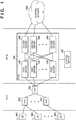
Fig. 7 is a block diagram for explaining an example of the protocol configuration of the mobile communication system according some embodiments. - The arrangement of a mobile communication system according to some embodiments of the present invention will be described with reference to
Fig. 1 . Although a mobile communication system complying with LTE will be described with reference toFig.1 , the present invention is also applicable to a mobile communication system complying with 3G or any other standard. The mobile communication system mainly includes eNBs 102, an S-GW 103, a P-GW 104, and acontrol server 107. The eNBs 102 and the S-GW 103 are provided by an MNO (Mobile Network Operator), and the P-GW 104 and thecontrol server 107 are provided by an MVNO (Mobile Virtual Network Operator). The P-GW 104 and thecontrol server 107 may be created by the MVNO itself, or may be created and operated by an MVNE (Mobile Virtual Network Enabler) according to an MVNO request. The S-GW 103 may be provided by the MVNO in place of the MNO. - UEs 101 are devices to which IMSIs (International Mobile Subscriber Identities) are assigned and can be, for example, mobile phones, personal computers, sensors, and actuators. The IMSI is identification information uniquely assigned to each device and is incorporated in the device in a state in which the IMSI is stored in, for example, a SIM.
- Each eNB 102 connects each UE 101 to the S-GW 103 and transfers a packet between the UE 101 and the S-GW 103. Each eNB 102 further provides a wireless resource management function, a mobility management function, and a scheduling function to each UE 101. The S-GW 103 provides a function of routing a packet from or to each UE 101. The S-GW 103 corresponds to the SGSN (packet access control node) of a 3G network.
- The P-GW 104 has a function of providing access to an
external network 108 to each UE 101. The P-GW 104 is a gateway apparatus functioning as the endpoint of a core network included in the mobile communication system. Theexternal network 108 may be a public network such as the Internet or a private network provided by each individual enterprise. The P-GW 104 corresponds to the GGSN (packet gateway node) of the 3G network. A packet from each eNB 102 to the P-GW 104 is transferred in an encapsulated form via a tunnel (GTP tunnel) established in accordance with a GTP (GPRS Tunneling Protocol). Any other L2 tunnel may be used in place of the GTP tunnel. - The P-GW 104 is formed from one or more
first servers 105 and one or moresecond servers 106. Eachfirst server 105 is connected to the S-GW 103 and transfers a packet received from the S-GW 103 to any one of the one or moresecond servers 106. Eachfirst server 105 transfers, to the S-GW 103, a packet received by one of the one or moresecond servers 106. - Each
second server 106 provides various services to the communications by the UE 101. For example, thesecond server 106 functions as NAT which performs processing in a network layer or a proxy which performs processing in an application layer. In addition, thesecond server 106 may perform processing for a still image and a moving image or credential assignment processing in place of the UE 101. - The upper limit of the number of servers simultaneously connectable to the S-GW 103 in the P-GW 104 is determined by the MNO. To solve this problem, the P-
GW 104 is arranged as follows. The servers are classified into servers (first servers 105) which perform packet (data) exchange with the S-GW 103 and servers (second servers 106) which perform access to theexternal network 108 and provide various additional services, thereby increasing the number ofsecond servers 106 so as to exceed the upper limit of connectable servers by the MNO. - Each of the one or more
first servers 105 and each of the one or moresecond servers 106 can be virtual machines, respectively, on a cloud. This cloud may be a public cloud such as an AWS or a private cloud provided for one enterprise. If the cloud is a public cloud, the one or morefirst servers 105 and the one or moresecond servers 106 may belong to a virtual private network on the cloud. For example, if the cloud is an AWS, a virtual private network is provided by a VPC (Virtual Private Cloud) function. - The provision of the P-GW 104 on the cloud can change the performance of the P-
GW 104 at an appropriate timing in accordance with the processing status of the P-GW 104. The change in performance of the P-GW 104 can be implemented by replacing (so-called scale up/scale down) one server with another server (a server having processing capability higher or lower than the previous server) or implemented by changing (so-called scale out/scale in) the number of servers. - The
control server 107 is a server which controls the operation of the P-GW 104. Thecontrol server 107 may be a virtual machine on a cloud or an on-premise server. Thecontrol server 107 may be formed from a single server or a plurality of servers. In this embodiment, thecontrol server 107 is exemplified as a server different from thefirst server 105 and thesecond server 106. However, one of thefirst servers 105 or one of thesecond servers 106 may have a function of thecontrol server 107. - The
control server 107 monitors the processing status of each of the one or morefirst servers 105 and each of the one or moresecond servers 106. Examples of the processing status of a monitoring target can be a CPU use rate, a memory use rate, a network use rate, an average throughput, the number of GTP sessions, and the like. A criterion of the processing status used to change the performance of thefirst server 105 may be different from a criterion of the processing status used to change the performance of thesecond server 106. Since thefirst server 105 performs the function of transferring a packet to thesecond server 106, the network performance tends to become a bottleneck. For this reason, thecontrol server 107 may change the performance of thefirst server 105 using the network performance (for example, the network use rate, the average throughput, or the like) as a criterion. Since thesecond server 106 performs various processing operations for a packet, and its calculation performance tends to become a bottleneck. For this reason, thecontrol server 107 may change the performance of thefirst server 105 using the calculation function (for example, the CPU use rate, the memory use rate, or the like) as a criterion. - The
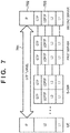
control server 107 may change the performance of the P-GW 104 regardless of the processing status of the P-GW 104. For example, thecontrol server 107 may change the performance of the P-GW 104 in accordance with an instruction from the administrator or user of the mobile communication system. In place of this, thecontrol server 107 may automatically change the performance of the P-GW 104 in accordance with the prescheduled settings. - Subsequently, an example of a protocol configuration of a U plane (user plane) of the mobile communication system in
Fig. 1 will be described with reference toFig. 7 . An end-to-end GTP tunnel 701 is established between theUE 101 and thesecond server 106. A packet transmitted from theUE 101 is transferred to thesecond server 106 via theGTP tunnel 701. An IP address (to be referred to as a user IP address hereinafter) used in anIP connection 702 with theUE 101 and an IP address (to be referred to as a transport IP address hereinafter) used in anIP connection 703 with thefirst server 105 are assigned to thesecond server 106. An IP packet is transferred from theUE 101 via theIP connection 702, and a GTP packet is transferred from thefirst server 105 via theIP connection 703. - Since the virtual machines in the virtual private network communicate with each other depending on a cloud service, an IP address in a subnetwork assigned to the virtual private network must be set in each virtual machine. The upper limit of the number of IP addresses in the subnetwork is determined by a cloud service. If this IP address in the subnetwork is assigned to the
UE 101, the number ofUEs 101 connectable to the mobile communication system is limited by the number of IP addresses in the virtual private network. For this reason, an address irrelevant to the address in the virtual environment subnet is assigned to theUE 101, NAT is performed at the virtual environment address assigned to a node when IP communication is performed with the outside of thesecond server 106 which performs GTP tunnel termination. In addition, in thesecond server 106, an IP address in the subnetwork assigned to the virtual private network is set as a transport IP address for causing thefirst server 105 to access thesecond server 106. An IP address not limited by the virtual private network is set as a user IP address for causing theUE 101 to access thesecond server 106. If the user IP address is additionally assigned to thesecond server 106 which performs GTP tunnel termination, the communication from theUE 101 to the user IP address of thesecond server 106 can reach thesecond server 106 without any NAT. - Subsequently, an example of the operation of the mobile communication system in
Fig. 1 will be described with reference toFig. 2 . This operation can be performed by causing a processor such as a CPU of each UE or each server to execute a program. In place of this, each UE and each server may include circuits (for example, ASICs) for executing the following operation. - In S1, the
UE 101 is attached to theeNB 102 and requests to generate a session with the P-GW 104 to the core network. TheUE 101 includes its own IMSI (to be referred to as an IMSI_A hereinafter) in this request. The S-GW 103 establishes a C-plane GTP tunnel (GTP-C) with one of the one or morefirst servers 105 and transfers the request from theUE 101 to thefirst server 105 via this GTP tunnel. For example, the S-GW 103 selects, by a round robin method, onefirst server 105 from the one or morefirst servers 105 connected to the S-GW 103. - Upon reception of the request from the
UE 101, thefirst server 105 determines whether thefirst server 105 refers to customer information and a session is established for the IMSI included in the request. This determination may be performed by causing thefirst server 105 to refer to the customer information or performed by thecontrol server 107 which has received the request from thefirst server 105. If the session can be established, thefirst server 105 assigns an IP address (to be referred to as 172.24.240.100) to theUE 101 and returns this IP address to theUE 101 in S2. - In S2, the
first server 105 sends, to thecontrol server 107, a request for assignment of thesecond server 106. In response to this request, thecontrol server 107 selects onesecond server 106 of the one or moresecond servers 106 and returns the transport IP address of thissecond server 106 to thefirst server 105. Thecontrol server 107 may select one second server 106 (for example, a server having a minimum load) in accordance with the processing status of the one or moresecond servers 106. Thefirst server 105 establishes a U-plane GTP tunnel (GTP-U) between theUE 101 and the selectedsecond server 106. In addition, thefirst server 105 notifies eachsecond server 106 of information concerning a pair of the IMSI of theUE 101 and the IP address assigned to theUE 101. This notification can be directly performed from thefirst server 105 to thesecond server 106 or may be performed via thecontrol server 107. For example, thefirst server 105 may register information concerning the pair of the IMSI and the IP address in thecontrol server 107, and thesecond server 105 may read out this information from thecontrol server 107. - In S3, the
UE 101 transmits, to thefirst server 105 via the GTP tunnel, an HTTP request toward the user IP address (to be referred to as 169.254.254.169) of thesecond server 106. TheUE 101 sets the IP address (172.24.240.100) assigned in S2 in the transmission source IP address of this HTTP request. The user IP address of thesecond server 106 may be stored in theUE 101 before the start of the operation in S1 or may be notified from thefirst server 105 to theUE 101 in S2. A single IP address may be shared as the user IP addresses of the plurality ofsecond servers 106. - In S4, the
first server 105, thefirst server 105 transfers, to thesecond server 106 via the GTP tunnel established in S2, the GTP packet transmitted from theUE 101 via the GTP tunnel. - In S5, the
second server 106 terminates the GTP tunnel to extract the IP packet from the GTP packet. In addition, thesecond server 106 resolves the IMSI of theUE 101 which has transmitted the HTTP request by using the information concerning the pair notified in S2 and the transmission source IP address of this HTTP request. In place of this, thesecond server 106 may transmit this transmission source IP address (the IP address of the UE 101) to thecontrol server 107, cause thecontrol server 107 to resolve the IMSI, and return it to thesecond server 106. - In S6, the
second server 106 sends an inquiry about processing to be executed to the resolved IMSI to thecontrol server 107. This processing includes processing to data transmitted from theUE 101 to theexternal network 108 and processing to data returned from theexternal network 108 to theUE 101. Thecontrol server 107 manages a table 300 shown inFig. 3 . Each entry of the table 300 indicates the processing contents to be executed for the data from theUE 101. Acolumn 301 indicates the IMSI of theUE 101 as the processing target. Acolumn 302 indicates a request protocol before conversion. Acolumn 303 indicates a request protocol after conversion. Acolumn 304 indicates a request destination. For example, the first-row entry of the table 300 indicates that an HTTP request from theUE 101 having the IMSI_A is converted into an HTTPS request and the converted request is transferred to https://server1.example.com/. Thesecond server 106 can perform individual processing for eachUE 101. For example, thesecond server 106 can similarly perform conversion from mqtt to mqtts, conversion from TCP to TCPS, and conversion from Websocket to Websocket over SSL. In addition to simple encryption, thesecond server 106 can perform conversion of a protocol itself such as HTTPS transfer of data received by a Raw TCP socket or data received by a UDP packet, and communication optimization between theUE 101 and thesecond server 106 such as compression of response contents from the external server or deletion of unnecessary header information. The latter function is particularly advantageous in a device such as a sensor or actuator aiming at energy saving. - In addition to the protocol conversion, the
second server 106 can add authentication information such as the user name and password of a site to be accessed by theUE 101, and add information referred to in processing on the server side, such as an identification number such as the IMEI (International Mobile Equipment Identifier) of theUE 101 and a time stamp indicating data reception time. Thesecond server 106 can also add a digital signature using secret information exchanged in advance with the reception side so as to allow the reception side to verify the authentication of the added information. Accordingly, access by spoofing of the third party can be prevented. - The
control server 107 provides an API for editing the table 300. Via this API (Application Programming Interface), the administrator of theUE 101 can edit (for example, add, change, or delete) the operations to be performed for hisown UE 101. Similarly, by using the API, the administrator of theUE 101 can also set information such as a user name and password for authentication and secret information for verifying authenticity of the information added by thesecond server 106. Thecontrol server 107 may provide a GUI (Graphical User Interface) for allowing the administrator of theUE 101 to facilitate the above processing. - In S7, the
control server 107 responds, to thesecond server 106, the operations to be performed of an entry indicating the result obtained by searching the table 300 using, as a key, the IMSI received from thesecond server 106. - In S8, the
second server 106 converts the HTTP request from theUE 101 into the HTTPS request in accordance with the operations to be performed received from thecontrol server 107 and transfers the HTTPS request to the destination (https://server1.example.com/) designated by the processing contents. In S9, thesecond server 106 receives a response to the HTTPS request from the destination. In S10, thesecond server 106 adds a GTP header to this response and transfers the resultant data to thefirst server 105. Thefirst server 105 as the transfer destination is the same as thefirst server 105 from which the HTTP request has been transferred in S4. In S11, thefirst server 105 transfers the response to theUE 101 via the GTP tunnel. After that, thefirst server 105 may cancel the GTP tunnel between theUE 101 and thesecond server 106. - According to the above processing, the common user IP address is assigned to the plurality of
second servers 106. Since the communication between thefirst server 105 and thesecond server 106 is identified by the transport IP address assigned to eachsecond server 106, identifiable GTP tunnels are established between the plurality ofUEs 101 and the plurality ofsecond servers 106. For this reason, even if the scale in/scale out operation or the scale down/scale up operation of thesecond server 106 is performed, the endpoint used as the destination of theUE 101, that is, the user IP address of thesecond server 106 need not be changed. - According to the above processing, since the user IP address of the
second server 106 can be set in advance in theUE 101, the overhead concerning the DNS processing for obtaining this IP address can be suppressed. In addition, the user IP address of thesecond server 106 can be set as a hardcode in theUE 101. This is particularly advantageous when theUE 101 is a weak embedded device such as a sensor. Even if the user IP address of thesecond server 106 set in theUE 101 cannot be changed, the communication partner of theUE 101 in theexternal network 108 can be changed by updating the table 300 of thecontrol server 107. - Subsequently, communication between the
first server 105 and thesecond server 106 in the processing ofFig. 2 will be described in detail. Although only one S-GW 103 is illustrated inFig. 1 , a general mobile communication system includes a plurality of S-GWs 103. A GTP tunnel between the S-GW 103 and the P-GW 104 (thefirst server 105 in practice) can be identified by a TEID (Tunnel Endpoint IDentifier). Eachfirst server 105 uniquely sets the TEID of the GTP tunnel with the S-GW 103 to prevent the interference between the GTP tunnels. However, if the respectivefirst servers 105 set the same TEID for the respective GTP tunnels and packets are transferred to the same second server from the respective GTP tunnels, the interference occurs between the GTP tunnels. - To solve this problem, the
control server 107 may monitor the TEID assigned by eachfirst server 105 and may select thesecond server 106 to which the packet is transferred from thefirst server 105 so as to prevent the interference between the GTP tunnels in thesecond servers 106. More specifically, thecontrol server 107 may select thesecond server 106 to which the packet is transferred from thefirst server 105 so as to prevent the TEIDs assigned by therespective servers 105 from overlapping in thesecond servers 106. - In place of this, another tunnel different from the GTP tunnel between the S-
GW 103 and thefirst server 105 may be set between thefirst server 105 and thesecond server 106, and a packet may be transferred from thefirst server 105 to thesecond server 106 via the other tunnel. The tunnel between thefirst server 105 and thesecond server 106 may be a GTP tunnel. Accordingly, the same software stack can be used in thefirst server 105 and thesecond server 106. - In the above embodiment, the
second server 106 terminates the GTP packet from theUE 101 to extract the IP address included in this GTP packet. In place of this, a third server different from thesecond server 106 may terminate a GTP packet from theUE 101. In this case, theUE 101 sets the destination IP address of the IP packet as the user IP address of the third server. Thesecond server 106 transfers, to the third server via the GTP tunnel or the other tunnel, the GTP packet transferred from thefirst server 105. - Subsequently, the arrangement of a mobile communication system according to another embodiment of the present invention will be described with reference to
Fig. 4 . The mobile communication system inFig. 4 is different from the mobile communication system inFig. 1 in the arrangement of a P-GW 104 and the operation of acontrol server 107. The rest may be the same as in the mobile communication system inFig. 1 . InFig. 4 , some constituent elements which are the same as those of the mobile communication system inFig. 1 will not be illustrated. The same description as inFig. 1 will be omitted. - A user having a
UE 101 connectable to the mobile communication system may want to access his own private network using thisUE 101 without going through the public network such as the Internet. For example, assume that a given enterprise purchases a plurality of SIMs and UEs assigned with these SIMs access the private network of this enterprise. Even if asecond server 106 belongs to the virtual private network on a cloud, thesecond server 106 can access another private network by a function provided by the cloud. The accessible other private network is another virtual private network present on the same cloud as thesecond server 106 and different from the virtual private network to which thesecond server 106 belongs, or a private network of the on-premise or another cloud connected by a leased line to the virtual private network to which thesecond server 106 belongs. - The
UE 101 of another user having no access right to a given private network of a given user should not access this private network. Due to the limitation of the cloud service, only single transfer information may be set for all servers belonging to the same subnetwork in the virtual private network. The transfer information here is information for defining an external network which theUE 101 can access. The transfer information includes, for example, a routing policy defined by a routing table, and an NACL (Network Access Control List) for access limitation. In the embodiment shown inFig. 1 , if all thesecond servers 106 are included in the same subnetwork, the single transfer information is applied to all theUEs 101 which can use this mobile communication system. As a result, theUEs 101 which can access the external private network cannot be limited. - In this embodiment, the plurality of
second servers 106 are divided into a plurality of groups, the respective groups are included in different subnetworks, and the transfer information is defined for each group. In the embodiment shown inFig. 4 , the plurality ofsecond servers 106 are classified intogroups second server 106. As in the embodiment shown inFig. 1 , thecontrol server 107 can change the performance of eachsecond server 106 included in each group, as needed. Thesecond servers 106 belonging to thegroup 401A can access only aprivate network 108A. For example, theprivate network 108A is another virtual private network of the same cloud as thesecond servers 106. If this cloud is the AWS, these virtual private networks can be implemented by the VPC function and are connected by the VPC peering function. Thesecond servers 106 included in thegroup 401B can access only aprivate network 108B. For example, theprivate network 108B is an on-premise private network. If thesecond servers 106 are included in the AWS, thesecond servers 106 and theprivate network 108B are connected by dedicated lines by the AWS Direct Connect function. Thesecond servers 106 included in thegroup 401C can access only aprivate network 108C. For example, theprivate network 108A is another virtual private network of the same cloud as thesecond servers 106. If this cloud is the AWS, these virtual private networks are implemented by the VPC function and are connected by the VPN connection function. Theprivate networks 108A to 108C are networks managed by different users. Thesecond servers 106 included in thegroup 401X can access only theInternet 108X. The one or morefirst servers 105 may belong to a subnetwork different from those of thesecond servers 106 or may belong to a virtual network different from those of thesecond servers 106. - Subsequently, the above transfer information will be described with reference to
Figs. 5A and 5B . The transfer information is formed from two tables 500 and 510 and managed by thecontrol server 107. The table 500 defines that a packet from eachUE 101 should be processed by thesecond server 106 of a specific group. Each entry (row) of the table 500 is generated for each IMSI. Acolumn 501 indicates an IMSI. Acolumn 502 indicates the group of thesecond server 106 which processes a packet from theUE 101 having each IMSI. - The table 510 indicates information concerning
second servers 106. Each entry (row) of the table 510 is generated for eachsecond server 106. Acolumn 511 indicates an identifier of thesecond server 106. The identifier of thesecond server 106 is unique in the mobile communication system. Acolumn 512 indicates the transport IP address of thesecond server 106. The transport IP address is set for eachsecond server 106. Acolumn 513 indicates the user IP address of thesecond server 106. The common user IP address may be set for the plurality ofsecond servers 106 or user IP addresses may be set for the plurality of second servers, respectively, as in the above embodiment. If the user IP address of thesecond server 106 is set in theUE 101 in advance, the table 510 need not include thecolumn 513. Acolumn 514 indicates the identifier of a group to which thesecond server 106 belongs. The group identifier is unique in the mobile communication system. Acolumn 515 indicates a subnetwork to which thesecond server 106 belongs. Acolumn 516 indicates the external network of packet transfer destination of thesecond server 106. The common transfer destination is set for thesecond servers 106 belonging to the same group. The administrator (for example, MVNO) of the mobile communication system creates and updates the tables 500 and 510 in accordance with a request from the user of the mobile communication system. - Subsequently, an example of the operation of the
control server 107 will be described with reference toFig. 6 . This operation can be done by causing a processor such as the CPU of thecontrol server 107 to execute a program. In place of this, thecontrol server 107 may include a circuit (for example, ASIC) which execute the following operation. The operation inFig. 6 is performed in S2 ofFig. 2 . In the following description, a case in which thefirst server 105 sends, to thecontrol server 107, an inquiry about the transport IP address of thesecond server 106 and the user IP address of thesecond server 106 will be described below. As described above, however, the user IP address of thesecond server 106 may be set in theUE 101 in advance. In this case, processing about the user IP address of thesecond server 106 in the following description may be omitted. - In S601, the
control server 107 receives an inquiry to obtain the transport IP address and user IP address of thesecond server 106 from thefirst server 105. This inquiry includes the IMSI of theUE 101 received from theUE 101 in S1 ofFig. 2 to thefirst server 105. - In S602, the
control server 107 specifies the group of thesecond servers 106 which are to process a packet from theUE 101 having the IMSI received in S601 with reference to the table 500. For example, if the IMSI received by thecontrol server 107 is "IMSI_1A", thecontrol server 107 specifies that thesecond servers 106 included in "Group A" should process the packet from theUE 101 having this IMSI. - In S603, the
control server 107 specifies the second servers included in the specified group and selects one of the second servers with reference to the table 510. For example, if the group specified by thecontrol server 107 is "Group A", thecontrol server 107 specifies "Node A1" and "Node A2" as thesecond servers 106 included in this group. Thecontrol server 107 may select onesecond server 106 based on the processing status of eachsecond server 106 included in the specified group. For example, thecontrol server 107 selects thesecond server 106 having a lowest load. - In S604, the
control server 107 reads out the transport IP address and user IP address of the selectedsecond server 106 from the table 510 and returns this transport IP address to thefirst server 105 as the inquiry source. - In S3 of
Fig. 2 , thefirst server 105 then notifies theUE 101 of the user IP address of the selectedsecond server 106. In S4 ofFig. 2 , theUE 101 transmits, to thefirst server 105, the HTTP request toward the user IP address of the selectedsecond server 106. In S5 ofFig. 2 , thefirst server 105 transfers the packet to the selectedsecond server 106 using the transport IP address of thesecond server 106 obtained in S604. After that, thesecond server 106 transfers the packet to theexternal network 108 in accordance with the transfer information set in the subnetwork to which thissecond server 106 belongs. - The packet from a
UE 101A whose IMSI is "IMSI_1A" is transferred to thesecond servers 106 included in thegroup 401A. Since thesecond servers 106 included in thegroup 401A can access only theprivate network 108A, the packet from theUE 101A is transferred to only theprivate network 108A, as indicated by a dottedline 402, but is not transmitted to other private networks, as indicated by a dottedline 403. Similarly, aUE 101B is transferred to only theprivate network 108B via thesecond servers 106 included in thegroup 401B. AUE 101C is transferred to only theprivate network 108C via thesecond servers 106 included in thegroup 401C. AUE 101X in which access to a private network is not set is transferred to only theInternet 108X via thesecond servers 106 included in thedefault group 401X. - In the embodiment shown in
Fig. 4 , thesecond server 106 terminates the GTP tunnel, extracts the IP packet, and then transfers the IP packet to the external network via the L3 connection. However, depending on a cloud service, the number of peer-connectable virtual networks and the number of virtual interfaces for private connections are limited. As a result, the number of private networks connectable to the P-GW 104 is limited. To solve this problem, thesecond server 106 may set the L2 tunnel with the server in the external private network and transfer the packet via the L2 tunnel. If the L2 tunnel is used, processing using the IP address of theUE 101 can be performed on the private network side. Whether the L2 tunnel or L3 connection is used can be set for each private network. - In the above description, a case in which the MVNO manages the P-
GW 104 has been described. However, the present invention is also applicable when the MNO manages the P-GW 104. A case in which P-GW 104 is L2-connected to theUE 101 has been described above. However, the present invention is also applicable when the P-GW 104 is L3-connected to theUE 101. - In each embodiment described above, the
first servers 105 may be classified into a C-plane server for performing communication with the S-GW 103 on the C plane and a P-plane server for performing communication with the S-GW 103 on the P plane. In addition, the C-plane servers can also be classified into a server for receiving data from the S-GW 103 via the GTP tunnel and a server for decapsulating this data and extracting the IP packet. - The present invention is not limited to the above-described embodiments, and various changes and modifications can be made within the spirit and scope of the present invention. Therefore, to apprise the public of the scope of the present invention, the following claims are made.
- Aspects and features of the present disclosure are set out in the following numbered clauses which contain the subject-matter of the claims of the parent European patent application as originally filed:
- 1. A control apparatus for a gateway in a mobile communication system, characterized in that
the gateway includes a first server configured to receive data from a user apparatus and one or more second servers configured to transfer the data received by the first server to an external network,
the one or more second servers are virtual machines on a cloud, and
the control apparatus performs
an operation of changing performance of the one or more second servers,
an operation of monitoring a processing status of the one or more second servers, and
an operation of selecting, from the one or more second servers in accordance with the processing status of the one or more second servers, a second server as a transfer destination of the data received from the user apparatus by the first server. - 2. The control apparatus according to
clause 1, characterized in that
the control apparatus
receives an identifier of the user apparatus from the gateway, and
returns, to the gateway, operations to be performed for data from the user apparatus having the identifier. - 3. The control apparatus according to
clause 2, characterized in that the operations to be performed include at least one of protocol conversion, data compression, header deletion, addition of user authentication information, addition of an identification number of the user apparatus, or addition of a digital signature. - 4. The control apparatus according to
clause - 5. The control apparatus according to any one of
clauses 1 to 4, characterized in that
a common address is set in the one or more second servers, and
the first server receives data having the common address as a destination from the user apparatus. - 6. The control apparatus according to clause 5, characterized in that the common address is different from an address set in the one or more second servers in order to cause the first server to communicate with the one or more second servers.
- 7. The control apparatus according to
clause 5 or 6, characterized in that
the first server transfers the received data to the second server selected by the control apparatus, and
the second server selected by the control apparatus performs processing in one of a network layer and an application layer for data transferred from the first server. - 8. The control apparatus according to
clause 5 or 6, characterized in that
the first server transfers the received data to the second server selected by the control apparatus, and
the second server selected by the control apparatus transfers, to another server configured to perform processing in one of a network layer and an application layer for data, the data transferred from the first server. - 9. The control apparatus according to any one of
clauses 1 to 8, characterized in that
the first server receives data from the user apparatus via an L2 tunnel, and
the first server transfers the data, via an L2 tunnel different from the L2 tunnel, to the second server selected by the control apparatus. - 10. The control apparatus according to any one of
clauses 1 to 8, characterized in that
the gateway includes a plurality of first servers,
the first server receives data from the user apparatus via an L2 tunnel, and
the control apparatus selects the second server serving as a transfer destination of data received from the user apparatus by the first server so as not to overlap identifiers of the L2 tunnels in the second servers. - 11. The control apparatus according to any one of
clauses 1 to 10, characterized in that
the gateway includes one or more first servers,
the one or more first servers are virtual machines on a cloud,
the control apparatus further performs
an operation of changing performance of the one or more second servers, and
an operation of monitoring a processing status of the one or more second servers, and
the control apparatus performs a change in performance of the one or more first servers and the change in performance of the one or more second servers based on different criteria. - 12. The control apparatus according to
clause 11, characterized in that the control apparatus performs the change in the performance of the one or more first servers based on network performance, and the change in the performance of the one or more second servers based on calculation performance. - 13. The control apparatus according to any one of
clauses 1 to 12, characterized in that
the one or more second servers are divided into a plurality of groups, and
the control apparatus selects, from a group corresponding to identification information of the user apparatus, the second server serving as a transfer destination of the data received from the user apparatus by the first server. - 14. The control apparatus according to clause 13, characterized in that different pieces of transfer information are set in the groups, respectively.
- 15. The control apparatus according to clause 14, characterized in that the transfer information defines an external network which the user apparatus can access.
- 16. The control apparatus according to any one of
clauses 1 to 15, characterized in that the second server and the external network communicate with each other via the L2 tunnel. - 17. The control apparatus according to any one of
clauses 1 to 15, characterized in that the second server and the external network communicate with each other via an L3 connection. - 18. A program for causing a computer to operate as a control apparatus of a gateway in a mobile communication system, characterized in that
the gateway includes a first server configured to receive data from a user apparatus and one or more second servers configured to transfer the data received by the first server to an external network,
the one or more second servers are virtual machines on a cloud, and
the program causes the computer to perform
an operation of changing performance of the one or more second servers,
an operation of monitoring a processing status of the one or more second servers, and
an operation of selecting, from the one or more second servers in accordance with the processing status of the one or more second servers, a second server as a transfer destination of the data received from the user apparatus by the first server.
Claims (15)
- A system comprising a control apparatus and a gateway functioning as the endpoint of a core network in a mobile communication system, characterized in that
the gateway includes a first server configured to receive data from a user apparatus and one or more second servers configured to transfer the data received by the first server to an external network, and
the control apparatus is configured to
receive an identifier of the user apparatus from the gateway, and
return, to the gateway, operations to be performed in an application layer for data from the user apparatus having the identifier. - The system according to claim 1, characterized in that the operations to be performed include at least one of protocol conversion, data compression, header deletion, addition of user authentication information, addition of an identification number of the user apparatus, or addition of a digital signature.
- The system according to claim 1 or 2, characterized in that the control apparatus is configured to provide an interface configured to edit the operations to be performed.
- The system according to any one of claims 1 to 3, characterized in that
a common address is set in the one or more second servers, and
the first server is configured to receive data having the common address as a destination from the user apparatus . - The system according to claim 4, characterized in that the common address is different from an address set in the one or more second servers in order to cause the first server to communicate with the one or more second servers.
- The system according to claim 4 or 5, characterized in that
the first server is configured to transfer the received data to the second server selected by the control apparatus, and
the second server selected by the control apparatus is configured to perform processing in one of a network layer and an application layer for data transferred from the first server. - The system according to claim 4 or 5, characterized in that
the first server is configured to transfer the received data to the second server selected by the control apparatus, and
the second server selected by the control apparatus is configured to transfer, to another server configured to perform processing in one of a network layer and an application layer for data, the data transferred from the first server. - The system according to any one of claims 1 to 7, characterized in that
the first server is configured to receive data from the user apparatus via an L2 tunnel, and
the first server is configured to transfer the data, via an L2 tunnel different from the L2 tunnel, to the second server selected by the control apparatus. - The system according to any one of claims 1 to 7, characterized in that
the gateway includes a plurality of first servers,
the first server is configured to receive data from the user apparatus via an L2 tunnel, and
the control apparatus is configured to select the second server serving as a transfer destination of data received from the user apparatus by the first server so as not to overlap identifiers of the L2 tunnels in the second servers. - The system according to any one of claims 1 to 9, characterized in that
the gateway includes one or more first servers,
the one or more first servers are virtual machines on a cloud,
the control apparatus is further configured to perform
an operation of changing performance of the one or more second servers, and
an operation of monitoring a processing status of the one or more second servers, and
the control apparatus is configured to perform a change in performance of the one or more first servers and the change in performance of the one or more second servers based on different criteria. - The system according to claim 10, characterized in that the control apparatus is configured to perform the change in the performance of the one or more first servers based on network performance, and the change in the performance of the one or more second servers based on calculation performance.
- The system according to any one of claims 1 to 11, characterized in that the second server and the external network communicate with each other via the L2 tunnel.
- The system according to any one of claims 1 to 12, characterized in that the second server and the external network communicate with each other via an L3 connection.
- The system according to any one of claims 1 to 13, characterized in that the one or more second servers are virtual machines on a cloud.
- A program for causing a computer to operate as a control apparatus of a gateway functioning as the endpoint of a core network in a mobile communication system, characterized in that
the gateway includes a first server configured to receive data from a user apparatus and one or more second servers configured to transfer the data received by the first server to an external network, and
the program causes the computer to perform
an operation of receiving an identifier of the user apparatus from the gateway, and
an operation of returning, to the gateway, operations to be performed in an application layer for data from the user apparatus having the identifier.
Priority Applications (1)
| Application Number | Priority Date | Filing Date | Title |
|---|---|---|---|
| EP20195331.2A EP3768041A1 (en) | 2015-09-29 | 2015-09-29 | Control apparatus for gateway in mobile communication system |
Applications Claiming Priority (3)
| Application Number | Priority Date | Filing Date | Title |
|---|---|---|---|
| EP15905355.2A EP3358876B1 (en) | 2015-09-29 | 2015-09-29 | Control apparatus for gateway in mobile communication system |
| EP20195331.2A EP3768041A1 (en) | 2015-09-29 | 2015-09-29 | Control apparatus for gateway in mobile communication system |
| PCT/JP2015/077610 WO2017056201A1 (en) | 2015-09-29 | 2015-09-29 | Control apparatus for gateway in mobile communication system |
Related Parent Applications (2)
| Application Number | Title | Priority Date | Filing Date |
|---|---|---|---|
| EP15905355.2A Division EP3358876B1 (en) | 2015-09-29 | 2015-09-29 | Control apparatus for gateway in mobile communication system |
| EP15905355.2A Division-Into EP3358876B1 (en) | 2015-09-29 | 2015-09-29 | Control apparatus for gateway in mobile communication system |
Publications (1)
| Publication Number | Publication Date |
|---|---|
| EP3768041A1 true EP3768041A1 (en) | 2021-01-20 |
Family
ID=58422921
Family Applications (3)
| Application Number | Title | Priority Date | Filing Date |
|---|---|---|---|
| EP20195338.7A Pending EP3767925A1 (en) | 2015-09-29 | 2015-09-29 | Control apparatus for gateway in mobile communication system |
| EP15905355.2A Active EP3358876B1 (en) | 2015-09-29 | 2015-09-29 | Control apparatus for gateway in mobile communication system |
| EP20195331.2A Pending EP3768041A1 (en) | 2015-09-29 | 2015-09-29 | Control apparatus for gateway in mobile communication system |
Family Applications Before (2)
| Application Number | Title | Priority Date | Filing Date |
|---|---|---|---|
| EP20195338.7A Pending EP3767925A1 (en) | 2015-09-29 | 2015-09-29 | Control apparatus for gateway in mobile communication system |
| EP15905355.2A Active EP3358876B1 (en) | 2015-09-29 | 2015-09-29 | Control apparatus for gateway in mobile communication system |
Country Status (6)
| Country | Link |
|---|---|
| US (5) | US11805429B2 (en) |
| EP (3) | EP3767925A1 (en) |
| JP (1) | JP6637059B2 (en) |
| CN (3) | CN108141772B (en) |
| SG (1) | SG11201802541QA (en) |
| WO (1) | WO2017056201A1 (en) |
Families Citing this family (8)
| Publication number | Priority date | Publication date | Assignee | Title |
|---|---|---|---|---|
| SG11201802541QA (en) | 2015-09-29 | 2018-04-27 | Soracom Inc | Control apparatus for gateway in mobile communication system |
| JP2018182608A (en) * | 2017-04-18 | 2018-11-15 | 株式会社メリテック | Mobile terminal, communication system, method, and computer program |
| JP6495381B2 (en) * | 2017-06-27 | 2019-04-03 | ソフトバンク株式会社 | Server apparatus, method for server apparatus to communicate with IoT device, computer program, communication system, and IoT device |
| JP6852955B2 (en) * | 2018-01-31 | 2021-03-31 | 日本電信電話株式会社 | Data collection method and metadata addition device and program |
| JP7036665B2 (en) * | 2018-05-22 | 2022-03-15 | 株式会社日立製作所 | Data management method and data management system |
| JP7388455B2 (en) * | 2020-01-28 | 2023-11-29 | 日本電信電話株式会社 | Transfer device, data processing method, and program |
| US20220141130A1 (en) * | 2020-11-02 | 2022-05-05 | Google Llc | Virtual Carrier Network |
| CN114039819B (en) * | 2022-01-07 | 2022-03-22 | 中大检测(湖南)股份有限公司 | Edge intelligent gateway based on 5G |
Citations (3)
| Publication number | Priority date | Publication date | Assignee | Title |
|---|---|---|---|---|
| EP1523142A1 (en) * | 2002-06-18 | 2005-04-13 | NTT DoCoMo, Inc. | Gateway apparatus, and method for processing signals in the gateway apparatus |
| WO2012047488A2 (en) * | 2010-09-27 | 2012-04-12 | T-Mobile Usa, Inc. | Insertion of user information into headers to enable targeted responses |
| EP2843885A1 (en) * | 2013-08-29 | 2015-03-04 | NTT DoCoMo, Inc. | Apparatus and method for implementing a packet gateway user plane |
Family Cites Families (75)
| Publication number | Priority date | Publication date | Assignee | Title |
|---|---|---|---|---|
| US5621728A (en) * | 1994-09-12 | 1997-04-15 | Bell Atlantic Network Services, Inc. | Level 1 gateway controlling broadband communications for video dial tone networks |
| WO2000041364A1 (en) * | 1998-12-28 | 2000-07-13 | Ntt Docomo, Inc. | Communication control system, communication method, server device, terminal, relay device, and communication system |
| CA2296213C (en) * | 2000-01-07 | 2009-04-14 | Sedona Networks Corporation | Distributed subscriber management |
| JP2002007749A (en) * | 2000-06-27 | 2002-01-11 | Hitachi Ltd | Server-allocating device, and system and method for providing service |
| US7284067B2 (en) * | 2002-02-20 | 2007-10-16 | Hewlett-Packard Development Company, L.P. | Method for integrated load balancing among peer servers |
| US7369538B1 (en) * | 2002-12-23 | 2008-05-06 | At&T Corp. | Method and apparatus for implementing a high-reliability load balanced easily upgradeable packet technology |
| WO2005039104A1 (en) * | 2003-08-27 | 2005-04-28 | Utstarcom(China)Co.Ltd. | A method and apparatus for implementing internet protocol (ip) multicasting service in the mobile communication system |
| US7197661B1 (en) * | 2003-12-05 | 2007-03-27 | F5 Networks, Inc. | System and method for dynamic mirroring of a network connection |
| DE102004013325A1 (en) * | 2004-03-17 | 2005-10-13 | Vodafone Holding Gmbh | APN access method for computers |
| TWI264658B (en) * | 2004-11-04 | 2006-10-21 | Universal Scient Ind Co Ltd | Method for universal storage |
| US8700729B2 (en) * | 2005-01-21 | 2014-04-15 | Robin Dua | Method and apparatus for managing credentials through a wireless network |
| US8073428B2 (en) * | 2006-09-22 | 2011-12-06 | Kineto Wireless, Inc. | Method and apparatus for securing communication between an access point and a network controller |
| US8312507B2 (en) * | 2006-10-17 | 2012-11-13 | A10 Networks, Inc. | System and method to apply network traffic policy to an application session |
| WO2008127512A2 (en) * | 2007-02-27 | 2008-10-23 | Roamware, Inc. | Method and system for providing camel services to a home network's outbound roamer without need for camel support or agreement |
| JP2009225171A (en) * | 2008-03-17 | 2009-10-01 | Fujitsu Ltd | Gateway device and its method |
| CN101999118B (en) * | 2008-04-07 | 2013-11-06 | 三菱电机株式会社 | Content display |
| US8635335B2 (en) * | 2009-01-28 | 2014-01-21 | Headwater Partners I Llc | System and method for wireless network offloading |
| JP5222662B2 (en) * | 2008-08-22 | 2013-06-26 | 株式会社日立製作所 | Content control system |
| US7996525B2 (en) | 2008-12-31 | 2011-08-09 | Sap Ag | Systems and methods for dynamically provisioning cloud computing resources |
| US8166187B2 (en) * | 2009-01-28 | 2012-04-24 | Cisco Technology, Inc. | Distributed IP gateway based on sharing a MAC address and IP address concurrently between a first network switching device and a second network switching device |
| US7970351B2 (en) * | 2009-03-03 | 2011-06-28 | E3 Llc | System and method for direct communication between wireless communication devices |
| US8060579B2 (en) * | 2009-06-12 | 2011-11-15 | Yahoo! Inc. | User location dependent DNS lookup |
| JP5506444B2 (en) * | 2010-02-18 | 2014-05-28 | 株式会社日立製作所 | Information system, apparatus and method |
| US9369437B2 (en) * | 2010-04-01 | 2016-06-14 | Cloudflare, Inc. | Internet-based proxy service to modify internet responses |
| US8914523B2 (en) * | 2010-05-17 | 2014-12-16 | Verizon Patent And Licensing Inc. | Dynamic internet protocol registry for mobile internet protocol based communications |
| US8542590B2 (en) * | 2010-11-30 | 2013-09-24 | Verizon Patent And Licensing Inc. | Bi-directional load balancing |
| US8559299B2 (en) * | 2010-11-30 | 2013-10-15 | Telefonaktiebolaget L M Ericsson (Publ) | Mobile gateways in pool for session resilience |
| KR101929533B1 (en) * | 2011-04-01 | 2018-12-17 | 인터디지탈 패튼 홀딩스, 인크 | System and method for sharing a common pdp context |
| US9241265B2 (en) * | 2011-05-13 | 2016-01-19 | Nokia Technologies Oy | Method and apparatus for handling incoming status messages |
| US8873398B2 (en) * | 2011-05-23 | 2014-10-28 | Telefonaktiebolaget L M Ericsson (Publ) | Implementing EPC in a cloud computer with openflow data plane |
| US9572011B2 (en) * | 2011-07-05 | 2017-02-14 | Mobileum, Inc. | Value added module in predictive intelligence |
| JP5765429B2 (en) * | 2011-09-30 | 2015-08-19 | 日本電気株式会社 | Communication system and method and apparatus |
| US9414268B2 (en) * | 2011-10-14 | 2016-08-09 | Telefonaktiebolaget Lm Ericsson (Publ) | User equipment and a radio network node, and methods therein for device-to-device communication |
| EP2592784B1 (en) * | 2011-11-14 | 2013-09-18 | Alcatel Lucent | Apparatus, method and computer program for routing data packets |
| US20140146785A1 (en) * | 2012-11-29 | 2014-05-29 | Alexandros Cavgalar | Gateway device, system and method |
| US9042247B2 (en) * | 2011-12-06 | 2015-05-26 | Wi-Lan Labs, Inc. | Systems and methods for preserving application identification information on handover in a communication network |
| EP2815544A4 (en) * | 2012-02-14 | 2015-11-25 | Neutral Tandem Inc D B A Inteliquent | Systems and methods for facilitation of communications sessions amongst a plurality of networks |
| WO2013139791A1 (en) * | 2012-03-21 | 2013-09-26 | Nokia Siemens Networks Oy | Lawful intercepts |
| US8885481B2 (en) * | 2012-03-29 | 2014-11-11 | Tata Consultancy Services Ltd. | System and method for hybrid telecommunication |
| US20150127628A1 (en) * | 2012-04-16 | 2015-05-07 | Onepatont Software Limited | Method and System for Display Dynamic & Accessible Actions with Unique Identifiers and Activities |
| WO2013167205A1 (en) * | 2012-05-11 | 2013-11-14 | Nokia Siemens Networks Oy | OFFLOADING OF TRAFFIC FROM THE ANCHOR DeNB IN A MOBILE RELAY SYSTEM |
| JP5537600B2 (en) * | 2012-05-15 | 2014-07-02 | 株式会社Nttドコモ | Control node and communication control method |
| JP5923393B2 (en) * | 2012-06-15 | 2016-05-24 | 株式会社Nttドコモ | Mobile communication network distribution system and mobile communication network distribution method |
| US9178880B1 (en) * | 2012-06-30 | 2015-11-03 | Emc Corporation | Gateway mediated mobile device authentication |
| WO2014008630A1 (en) * | 2012-07-10 | 2014-01-16 | Telefonaktiebolaget L M Ericsson(Publ) | Reducing signaling load caused by change of terminal location |
| US9014036B2 (en) * | 2012-10-19 | 2015-04-21 | Verizon Patent And Licensing Inc. | Dynamic band selection and aggregation |
| EP2908480B1 (en) * | 2012-11-09 | 2017-10-25 | Huawei Technologies Co., Ltd. | Method, forwarding-plane apparatus, and network device for processing packet |
| CN102984025B (en) * | 2012-11-23 | 2015-09-30 | 华为技术有限公司 | The method of testing of gateway device virtual tunnel performance, Apparatus and system |
| US9065699B2 (en) * | 2012-11-30 | 2015-06-23 | Cognosos, Inc. | Methods and systems for a distributed radio communications network |
| US9071677B2 (en) | 2013-02-12 | 2015-06-30 | Unify Square, Inc. | Enhanced data capture, analysis, and reporting for unified communications |
| US9344949B2 (en) * | 2013-03-14 | 2016-05-17 | T-Mobile Usa, Inc. | System and method for optimizing a media gateway selection in mobile switching center pool architecture |
| US10292040B2 (en) * | 2013-03-29 | 2019-05-14 | Roamware, Inc. | Methods and apparatus for facilitating LTE roaming between home and visited operators |
| WO2014160978A2 (en) * | 2013-03-29 | 2014-10-02 | Mobileum Inc. | ENABLING VOICE OVER LONG TERM EVOLUTION (VoLTE) SERVICES FOR NON-VoLTE INBOUND ROAMERS |
| US20160127506A1 (en) * | 2013-05-27 | 2016-05-05 | Nec Corporation | Network control apparatus, network control method, program, and communication system |
| WO2015008410A1 (en) * | 2013-07-19 | 2015-01-22 | 日本電気株式会社 | Network system, control device, control method, and non-transitory computer-readable medium |
| US9521077B2 (en) * | 2013-07-22 | 2016-12-13 | Verizon Patent And Licensing Inc. | Network connection via a proxy device using a generic access point name |
| US9819505B2 (en) * | 2013-08-20 | 2017-11-14 | Cisco Technology, Inc. | Group bundling priority dissemination through link-state routing protocol in a network environment |
| US9247294B2 (en) * | 2013-10-24 | 2016-01-26 | At&T Intellectual Property I, Lp | Method and apparatus for managing communication activities of a communication device |
| US20150124622A1 (en) * | 2013-11-01 | 2015-05-07 | Movik Networks, Inc. | Multi-Interface, Multi-Layer State-full Load Balancer For RAN-Analytics Deployments In Multi-Chassis, Cloud And Virtual Server Environments |
| CN104717081B (en) * | 2013-12-13 | 2018-01-23 | 杭州华为数字技术有限公司 | The implementation method and device of a kind of gateway function |
| CN103812931B (en) * | 2014-01-24 | 2015-07-29 | 腾讯科技(深圳)有限公司 | A kind of user profile shares method, Apparatus and system |
| JP2015149578A (en) * | 2014-02-06 | 2015-08-20 | 株式会社日立製作所 | operation management apparatus |
| CN104123333B (en) * | 2014-03-17 | 2017-02-15 | 腾讯科技(深圳)有限公司 | Data processing method and device for location sharing |
| US20150350912A1 (en) * | 2014-05-28 | 2015-12-03 | Telefonaktiebolaget L M Ericsson (Publ) | Residential service delivery based on unique residential apn |
| US9629060B2 (en) * | 2014-06-06 | 2017-04-18 | Oracle International Corporation | Flexible routing policy for Wi-Fi offloaded cellular data |
| CN104144159B (en) * | 2014-06-26 | 2016-04-13 | 腾讯科技(深圳)有限公司 | Intelligent heartbeat keepalive method and intelligent heartbeat keep-alive system |
| US10136284B2 (en) * | 2014-07-07 | 2018-11-20 | Convida Wireless, Llc | Coordinated grouping for machine type communications group based services |
| US9830624B2 (en) * | 2014-10-28 | 2017-11-28 | Bau Llc | Systems and methods for resource utilization management |
| WO2016094572A1 (en) * | 2014-12-11 | 2016-06-16 | Kodiak Networks, Inc. | System for inter-communication between integrated digital enhanced network systems and push-to-talk-over-cellular systems |
| CN104539716A (en) * | 2015-01-04 | 2015-04-22 | 国网四川省电力公司信息通信公司 | Cloud desktop management system desktop virtual machine dispatching control system and method |
| US10805110B2 (en) * | 2015-03-27 | 2020-10-13 | Akamai Technologies, Inc. | Traffic delivery using anycast and end user-based mapping in an overlay network |
| US10798048B2 (en) * | 2015-04-07 | 2020-10-06 | Nicira, Inc. | Address resolution protocol suppression using a flow-based forwarding element |
| US10348625B2 (en) * | 2015-06-30 | 2019-07-09 | Nicira, Inc. | Sharing common L2 segment in a virtual distributed router environment |
| KR102095893B1 (en) * | 2015-08-25 | 2020-04-01 | 후아웨이 테크놀러지 컴퍼니 리미티드 | Service processing method and device |
| SG11201802541QA (en) * | 2015-09-29 | 2018-04-27 | Soracom Inc | Control apparatus for gateway in mobile communication system |
-
2015
- 2015-09-29 SG SG11201802541QA patent/SG11201802541QA/en unknown
- 2015-09-29 CN CN201580083406.3A patent/CN108141772B/en active Active
- 2015-09-29 CN CN202210047799.4A patent/CN114205925B/en active Active
- 2015-09-29 EP EP20195338.7A patent/EP3767925A1/en active Pending
- 2015-09-29 EP EP15905355.2A patent/EP3358876B1/en active Active
- 2015-09-29 WO PCT/JP2015/077610 patent/WO2017056201A1/en active Application Filing
- 2015-09-29 EP EP20195331.2A patent/EP3768041A1/en active Pending
- 2015-09-29 CN CN202210047901.0A patent/CN114205926B/en active Active
- 2015-09-29 JP JP2017542563A patent/JP6637059B2/en active Active
-
2018
- 2018-03-28 US US15/764,122 patent/US11805429B2/en active Active
- 2018-05-03 US US15/970,433 patent/US20180255132A1/en not_active Abandoned
-
2019
- 2019-07-24 US US16/520,703 patent/US11337084B2/en active Active
- 2019-07-24 US US16/520,694 patent/US11595830B2/en active Active
-
2023
- 2023-09-22 US US18/371,827 patent/US20240015533A1/en active Pending
Patent Citations (3)
| Publication number | Priority date | Publication date | Assignee | Title |
|---|---|---|---|---|
| EP1523142A1 (en) * | 2002-06-18 | 2005-04-13 | NTT DoCoMo, Inc. | Gateway apparatus, and method for processing signals in the gateway apparatus |
| WO2012047488A2 (en) * | 2010-09-27 | 2012-04-12 | T-Mobile Usa, Inc. | Insertion of user information into headers to enable targeted responses |
| EP2843885A1 (en) * | 2013-08-29 | 2015-03-04 | NTT DoCoMo, Inc. | Apparatus and method for implementing a packet gateway user plane |
Also Published As
| Publication number | Publication date |
|---|---|
| CN108141772B (en) | 2022-02-08 |
| US20240015533A1 (en) | 2024-01-11 |
| CN108141772A (en) | 2018-06-08 |
| US20190349791A1 (en) | 2019-11-14 |
| SG11201802541QA (en) | 2018-04-27 |
| US20190349790A1 (en) | 2019-11-14 |
| CN114205926A (en) | 2022-03-18 |
| JPWO2017056201A1 (en) | 2018-08-30 |
| US11805429B2 (en) | 2023-10-31 |
| EP3358876B1 (en) | 2020-12-23 |
| EP3358876A4 (en) | 2019-07-10 |
| WO2017056201A1 (en) | 2017-04-06 |
| JP6637059B2 (en) | 2020-01-29 |
| CN114205926B (en) | 2024-01-16 |
| EP3767925A1 (en) | 2021-01-20 |
| EP3358876A1 (en) | 2018-08-08 |
| CN114205925A (en) | 2022-03-18 |
| US11337084B2 (en) | 2022-05-17 |
| US20190059005A1 (en) | 2019-02-21 |
| CN114205925B (en) | 2024-03-19 |
| US20180255132A1 (en) | 2018-09-06 |
| US11595830B2 (en) | 2023-02-28 |
Similar Documents
| Publication | Publication Date | Title |
|---|---|---|
| US11337084B2 (en) | Control apparatus for gateway in mobile communication system | |
| US11683087B2 (en) | Cloud based access solution for enterprise deployment | |
| EP3567896B1 (en) | Communication method, device and system | |
| KR102087226B1 (en) | Method for sharing network based on software defined network to support multiple operator | |
| EP2876914B1 (en) | Providing in-line services through radio access network resources under control of a mobile packet core in a network environment | |
| JP2018521573A (en) | SDN security | |
| JP5192047B2 (en) | Communication control system, communication system, and communication control method | |
| CN111480354A (en) | Data routing in a communication system | |
| CN105874756B (en) | The transmission method and equipment of control signaling | |
| CN108141743B (en) | Methods, networks, apparatus, systems, media and devices handling communication exchanges | |
| EP4030864B1 (en) | Binding of multiple sessions | |
| CN107810620A (en) | Binding service is provided at non-anchor node | |
| CN109644161B (en) | MP-GW port mapping method and system divided according to service flow in multi-path environment | |
| KR101481337B1 (en) | Mobile Communication System Based on Software Defined Networks and Method for Processing Access of Mobile Equipment thereof | |
| JP6976199B2 (en) | Information processing server and information processing method | |
| EP3820184B1 (en) | Telecommunication hub | |
| WO2017166190A1 (en) | Handover requests in access network | |
| CN117378175A (en) | System and method for establishing a dual layer PDU session |
Legal Events
| Date | Code | Title | Description |
|---|---|---|---|
| PUAI | Public reference made under article 153(3) epc to a published international application that has entered the european phase |
Free format text: ORIGINAL CODE: 0009012 |
|
| STAA | Information on the status of an ep patent application or granted ep patent |
Free format text: STATUS: REQUEST FOR EXAMINATION WAS MADE |
|
| 17P | Request for examination filed |
Effective date: 20200909 |
|
| AC | Divisional application: reference to earlier application |
Ref document number: 3358876 Country of ref document: EP Kind code of ref document: P |
|
| AK | Designated contracting states |
Kind code of ref document: A1 Designated state(s): AL AT BE BG CH CY CZ DE DK EE ES FI FR GB GR HR HU IE IS IT LI LT LU LV MC MK MT NL NO PL PT RO RS SE SI SK SM TR |
|
| RBV | Designated contracting states (corrected) |
Designated state(s): AL AT BE BG CH CY CZ DE DK EE ES FI FR GB GR HR HU IE IS IT LI LT LU LV MC MK MT NL NO PL PT RO RS SE SI SK SM TR |