EP3768028B1 - Kommunikationsverfahren und -vorrichtung - Google Patents
Kommunikationsverfahren und -vorrichtung Download PDFInfo
- Publication number
- EP3768028B1 EP3768028B1 EP19781900.6A EP19781900A EP3768028B1 EP 3768028 B1 EP3768028 B1 EP 3768028B1 EP 19781900 A EP19781900 A EP 19781900A EP 3768028 B1 EP3768028 B1 EP 3768028B1
- Authority
- EP
- European Patent Office
- Prior art keywords
- message
- offset information
- terminal device
- information
- offset
- Prior art date
- Legal status (The legal status is an assumption and is not a legal conclusion. Google has not performed a legal analysis and makes no representation as to the accuracy of the status listed.)
- Active
Links
- 238000000034 method Methods 0.000 title claims description 74
- 238000004891 communication Methods 0.000 title claims description 41
- 238000012544 monitoring process Methods 0.000 claims description 49
- 230000004044 response Effects 0.000 claims description 14
- 230000008054 signal transmission Effects 0.000 claims description 8
- 230000005540 biological transmission Effects 0.000 description 44
- 230000008569 process Effects 0.000 description 34
- 238000010586 diagram Methods 0.000 description 20
- 238000010295 mobile communication Methods 0.000 description 13
- 230000011664 signaling Effects 0.000 description 12
- 238000012545 processing Methods 0.000 description 9
- 230000007774 longterm Effects 0.000 description 8
- 230000006870 function Effects 0.000 description 7
- 230000007246 mechanism Effects 0.000 description 7
- 230000009471 action Effects 0.000 description 5
- 230000001413 cellular effect Effects 0.000 description 3
- 238000006243 chemical reaction Methods 0.000 description 3
- 230000003190 augmentative effect Effects 0.000 description 2
- 230000010267 cellular communication Effects 0.000 description 1
- 230000001419 dependent effect Effects 0.000 description 1
- 238000005516 engineering process Methods 0.000 description 1
- VJYFKVYYMZPMAB-UHFFFAOYSA-N ethoprophos Chemical compound CCCSP(=O)(OCC)SCCC VJYFKVYYMZPMAB-UHFFFAOYSA-N 0.000 description 1
- 238000011160 research Methods 0.000 description 1
- 238000001228 spectrum Methods 0.000 description 1
- 230000007480 spreading Effects 0.000 description 1
Images


Classifications
-
- H—ELECTRICITY
- H04—ELECTRIC COMMUNICATION TECHNIQUE
- H04W—WIRELESS COMMUNICATION NETWORKS
- H04W74/00—Wireless channel access
- H04W74/002—Transmission of channel access control information
- H04W74/006—Transmission of channel access control information in the downlink, i.e. towards the terminal
-
- H—ELECTRICITY
- H04—ELECTRIC COMMUNICATION TECHNIQUE
- H04B—TRANSMISSION
- H04B7/00—Radio transmission systems, i.e. using radiation field
- H04B7/14—Relay systems
- H04B7/15—Active relay systems
- H04B7/185—Space-based or airborne stations; Stations for satellite systems
- H04B7/1851—Systems using a satellite or space-based relay
- H04B7/18513—Transmission in a satellite or space-based system
-
- H—ELECTRICITY
- H04—ELECTRIC COMMUNICATION TECHNIQUE
- H04W—WIRELESS COMMUNICATION NETWORKS
- H04W56/00—Synchronisation arrangements
- H04W56/004—Synchronisation arrangements compensating for timing error of reception due to propagation delay
- H04W56/0045—Synchronisation arrangements compensating for timing error of reception due to propagation delay compensating for timing error by altering transmission time
-
- H—ELECTRICITY
- H04—ELECTRIC COMMUNICATION TECHNIQUE
- H04W—WIRELESS COMMUNICATION NETWORKS
- H04W72/00—Local resource management
- H04W72/04—Wireless resource allocation
- H04W72/044—Wireless resource allocation based on the type of the allocated resource
- H04W72/0446—Resources in time domain, e.g. slots or frames
-
- H—ELECTRICITY
- H04—ELECTRIC COMMUNICATION TECHNIQUE
- H04W—WIRELESS COMMUNICATION NETWORKS
- H04W74/00—Wireless channel access
- H04W74/08—Non-scheduled access, e.g. ALOHA
- H04W74/0833—Random access procedures, e.g. with 4-step access
-
- H—ELECTRICITY
- H04—ELECTRIC COMMUNICATION TECHNIQUE
- H04W—WIRELESS COMMUNICATION NETWORKS
- H04W84/00—Network topologies
- H04W84/02—Hierarchically pre-organised networks, e.g. paging networks, cellular networks, WLAN [Wireless Local Area Network] or WLL [Wireless Local Loop]
- H04W84/04—Large scale networks; Deep hierarchical networks
- H04W84/06—Airborne or Satellite Networks
Definitions
- This application relates to the field of communications technologies, and in particular, to a communications methods, apparatuses and computer readable storage media.
- a terminal device In a mobile communications system such as a long term evolution (long term evolution, LTE) system or a new radio (new radio, NR) system, a terminal device needs to access the mobile communications system through a random access (random access, RA) process.
- the terminal device sends a random access preamble (preamble) to initiate the random access process, and receives a random access response (random access response, RAR) in a RAR monitoring window after sending the preamble.
- the RAR is scrambled by using a random access radio network temporary identifier (random access radio network temporary identifier, RA-RNTI) corresponding to the terminal device.
- RA-RNTI random access radio network temporary identifier
- the mobile communications system may not only include a terrestrial cellular system, but also extend wireless signal coverage through a satellite, thereby implementing convergence of terrestrial cellular communications and satellite communications over an air interface.
- the satellite has a height of hundreds of kilometers to tens of thousands of kilometers, and a unidirectional transmission delay of sending a satellite signal to the terrestrial cellular system is between several milliseconds and more than 100 milliseconds.
- US20180035470 relates to method and apparatus for improving msg3 transmission of random access procedure in a wireless communication system.
- WO 2017/193341 relates to random access method and device.
- US 2014/362798 relates to shifting HARQ feedback for cognitive-radio-based TD-LTE systems.
- ERICSSON "Random Access in NR", 3GPP DRAFT; R2-1704403-RANDOM ACCESS IN NR, 3RD GENERATION PARTNERSHIP PROJECT (3GPP), MOBILE COMPETENCE CENTRE ; 650, ROUTE DES LUCIOLES ; F-06921 SOPHIA-ANTIPOLIS CEDEX ; FRANCE vol. RAN WG2, no. Hangzhou; 20170515-20170519 14 May 2017 relates to random access in NR.
- Implementations of this application provide a communications methods, apparatuses and computer readable storage media, to resolve a problem of how a terminal device accesses a network in a long transmission and high delay scenario.
- the terminal device determines a start time of the RAR monitoring window based on the time offset value indicated by the first offset information, so that the terminal device can monitor, in the offset RAR monitoring window, the RAR sent by the network device, and an opportunity that the terminal device successfully receives the RAR is improved.
- the terminal device can access the network device through a random access process in a long-distance transmission and high delay scenario.
- a new radio new radio
- GSM global system for mobile communications
- CDMA code division multiple access
- WCDMA wideband code division multiple access
- general packet radio service general packet radio service, GPRS
- LTE long term evolution
- LTE-A long term evolution-advanced
- UMTS universal mobile telecommunications system
- eLTE evolved long term evolution
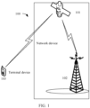
- FIG. 1 is a schematic architectural diagram of a mobile communications system to which a communication method according to an implementation of this application is applicable.
- the mobile communications system 100 includes network devices (a satellite 101 and a gateway 102) and a terminal device 103.
- the terminal device 103 may be connected to the gateway 102 through the satellite 101, and then connected to a core network device in the mobile communications system through the gateway 102, to implement data transmission.
- the gateway 102 may be a radio access device in any standard or a chip disposed in the radio access device, for example, an evolved NodeB (evolved Node B, eNB), a radio network controller (radio network controller, RNC), a NodeB (Node B, NB), a base station controller (base station controller, BSC), a base transceiver station (base transceiver station, BTS), a home base station (such as a home evolved NodeB or a home NodeB, HNB), a baseband unit (baseband unit, BBU), an access point (access point, AP) in a wireless fidelity (wireless fidelity, Wi-Fi) system, a wireless relay node, a wireless backhaul node, or a transmission point (transmission and reception point, TRP or transmission point, TP); or may be a gNB or a transmission point (TRP or TP) in a 5G (NR) system, or one antenna panel or a group
- RNC radio network
- the satellite 101 may be an artificial satellite having a satellite-borne processing capability. In this case, some or all of functions of the gateway 102 may be integrated to the satellite 101.
- the satellite 101 may be a satellite that supports only bent pipe (bend pipe) transponding.
- the bent pipe transponding means that the satellite does not demodulate a signal received from a terrestrial transmitter, but directly forwards the signal to a terrestrial receiver after performing frequency conversion on the signal.
- the terminal device 103 may alternatively directly access the mobile communications system through the gateway 102.
- the terminal device is a device having a wireless transceiver function or a chip that can be disposed in the device.
- the device having the wireless transceiver function may also be referred to as user equipment (user equipment, UE), an access terminal, a subscriber unit, a subscriber station, a mobile station, a remote station, a remote terminal, a mobile device, a user terminal, a user agent, or a user apparatus.
- the terminal device in the implementations of this application may be a mobile phone (mobile phone), a tablet computer (Pad), a computer having a wireless transceiver function, a virtual reality (virtual reality, VR) terminal, an augmented reality (augmented reality, AR) terminal, a wireless terminal in industrial control (industrial control), a wireless terminal in self driving (self driving), a wireless terminal in telemedicine (remote medical), a wireless terminal in a smart grid (smart grid), a wireless terminal in transportation safety (transportation safety), a wireless terminal in a smart city (smart city), a wireless terminal in a smart home (smart home), or the like.
- An application scenario is not limited in the implementations of this application.
- the device having the wireless transceiver function and the chip that can be disposed in the device are collectively referred to as the terminal device.
- a network architecture and a service scenario described in the implementations of this application are intended to describe the technical solutions in the implementations of this application more clearly, and do not constitute a limitation on the technical solutions provided in the implementations of this application.
- a person of ordinary skill in the art may know that: With evolution of the network architecture and emergence of new service scenarios, the technical solutions provided in the implementations of this application are also applicable to similar technical problems.
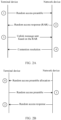
- the terminal device To implement data transmission between the terminal device and the network device, the terminal device establishes a connection to the network device through a random access process.
- the random access process includes a schematic diagram of a contention-based random access process shown in FIG. 2A and a schematic diagram of a non-contention-based random access process shown in FIG. 2B .
- the contention-based random access process mainly includes a four-step message flow: Message 1: The terminal device sends a random access preamble (preamble) to the network device, to initiate the random access process.
- Message 1 The terminal device sends a random access preamble (preamble) to the network device, to initiate the random access process.
- the terminal device randomly selects the random access preamble, and sends the random access preamble on a random access resource corresponding to the random access preamble.
- the network device sends a random access response to the terminal device.
- the network device After successfully detecting the random access preamble, the network device sends the random access response (random access response, RAR) corresponding to the random access preamble.
- the RAR may include an identifier of the random preamble, a timing advance (timing advance, TA), and resource scheduling indication information, for example, an uplink grant (UL grant).
- the terminal device starts to monitor the RAR in a RAR monitoring window after a first time interval after sending the random access preamble.
- the first time interval is preset in a 3GPP protocol.
- a start time of the RAR monitoring window is after the last subframe (sub-frame) in which the random access preamble is sent + three subframes (the first time interval).
- a start time of the RAR monitoring window is after the last symbol (symbol) on which the random access preamble is sent + a fixed time (the first time interval).
- the terminal device sends an uplink message to the network device based on the RAR.
- the terminal device may obtain the TA and an uplink resource indication that are included in the RAR, where the TA is used by the terminal device to perform uplink synchronization.
- the terminal device After performing uplink synchronization by using the TA, the terminal device sends the uplink message after a second time interval on an uplink resource indicated by the resource scheduling indication information.
- the uplink message may include control signaling or uplink data.
- the control signaling may be a radio resource control (radio resource control, RRC) message, for example, an RRC connection setup request message or an RRC connection resume request message.
- RRC radio resource control
- the second time interval is preset in the 3GPP protocol.
- a time of sending the uplink message is after a subframe in which the RAR is received + four subframes (the second time interval).
- a time of sending the uplink message is after a time at which the RAR is received + a fixed time (the second time interval).
- the network device sends a contention resolution message to the terminal device.
- the contention resolution message carries an identifier of the terminal device, to complete contention resolution.
- the non-contention-based random access process mainly includes a three-step message flow: Message 0: The network device sends random access preamble allocation information to the terminal device.
- the network device determines a random access preamble, and notifies the terminal device of the random access preamble by using the random access preamble allocation information. Because the random access preamble is allocated by the network device, the terminal device does not need to randomly select the random access preamble, to avoid contention with another terminal device.
- the terminal device sends, to the network device, the random access preamble indicated in the random access preamble allocation information.
- the network device sends a random access response to the terminal device.
- the terminal device receives the random access response after a preset time interval after sending the random access preamble; and sends an uplink message after a preset time interval based on an uplink resource and a TA that are indicated in the random access response, where the uplink message may include control signaling or uplink data.
- the terminal device may fail to receive the RAR sent by the network device, causing a failure of the random access process.
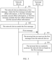
- an implementation of this application provides a communication method for this scenario, to improve a possibility that the terminal device successfully receives the RAR.
- the method includes the following content.
- Step 301 The network device determines a first message, where the first message includes first offset information, or the first message includes second offset information, or the first message includes the first offset information and the second offset information.
- the first offset information is used to indicate a time offset value of a RAR monitoring window for monitoring a RAR; and the second offset information is used to indicate a time offset value for sending a second message, and the second message is a message sent by the terminal device based on the RAR.
- the second message is the message 3.
- the second message is the uplink data or signaling sent by the terminal device based on the RAR.
- Step 302 The network device sends the first message.
- the network device may send the first message in a broadcast or multicast manner, or may send the first message to the terminal device by using higher layer signaling specific to (specific to) the terminal device. This is not limited in this implementation of this application.
- the first message may be a remaining minimum system message (remaining minimum system information, RMSI), or may be a system message (system information, SI), or may be a message such as a system information block 1 (system information block 1, SIB 1).
- RMSI remaining minimum system information
- SI system message
- SIB system information block 1
- a name of the first message is not limited in this implementation of this application, and examples are not described one by one herein.
- Step 303 The terminal device receives the first message from the network device.
- Step 304 The terminal device randomly accesses the network device based on the first message.
- the first message may be a message periodically broadcast by the network device in a cell served by the network device.
- the terminal device may receive the first message from the network device, to randomly access the network device based on the first offset information and/or the second offset information in the first message.
- the terminal device may read the system message sent by the network device, to obtain the first offset information and/or the second offset information; or in the non-contention-based random access process, the terminal device may read the system message to obtain the first offset information and/or the second offset information, or may receive the higher layer signaling (for example, signaling carrying random access preamble allocation information) specific to the terminal device to obtain the first offset information and/or the second offset information.
- the higher layer signaling for example, signaling carrying random access preamble allocation information
- the time offset value indicated by the first offset information and the time offset value indicated by the second offset information is determined based on signal transmission duration between the network device and the terminal device.
- T1 is the signal transmission duration between the network device and the terminal device
- ⁇ ⁇ represents a rounding-up operation.
- a value of ⁇ may be 1, 2, or the like, and T1 may be a value obtained by dividing a distance between the network device and the terminal device by a speed of light.
- ⁇ is a number greater than 0.
- a value of ⁇ may be 1, 2, or the like.
- the distance between the network device and the terminal device is 1600 kilometers.
- the signal transmission duration between the network device and the terminal device is 5.28 ms, and the network device may set the time offset value indicated by the first offset information to 6 ms, and set the time offset value indicated by the second offset information to 12 ms.
- the first offset information indicates the time offset value of the RAR monitoring window for monitoring the RAR by the terminal device.
- the terminal device may determine a start time of the RAR monitoring window based on the first offset information. Specifically, the terminal device may use, as the start time of the RAR monitoring window, a time point whose distance from the last symbol on which the terminal device sends the random access preamble is a sum of a first time interval and the time offset value indicated by the first offset information.
- the network device indicates the time offset value of the RAR monitoring window by using the first offset information.
- the terminal device determines a position of the RAR monitoring window based on the time offset value indicated by the first offset information, so that the terminal device can monitor, in the offset RAR monitoring window, the RAR sent by the network device, and an opportunity that the terminal device successfully receives the RAR is improved.
- the terminal device can access the network device through the random access process in the long-distance transmission and high delay scenario.
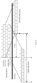
- FIG. 4 is a schematic diagram of a RAR monitoring window according to an implementation of this application.
- a distance between the start time of the RAR monitoring window and the last symbol on which the terminal device sends the random access preamble is the first time interval.
- a transmission delay of the RAR sent by the network device is relatively high, and the terminal device cannot detect, in the RAR monitoring window that is not offset, the RAR sent by the network device.
- the distance between the start time of the RAR monitoring window and the last symbol on which the terminal device sends the random access preamble is the sum of the first time interval and the time offset value indicated by the first offset information.
- the terminal device starts to monitor the RAR at a position whose distance from the last symbol on which the random access preamble is sent is the sum of the first time interval and the time offset value indicated by the first offset information, to reduce a probability that the terminal device cannot detect the RAR in the RAR window due to the relatively high transmission delay of the RAR that is caused by the relatively large distance between the terminal device and the network device.
- the network device respectively configures TAs for the different terminal devices, and includes the TAs in RARs.
- a terminal device may perform uplink transmission (for example, send the second message in this implementation of this application) based on the TA and an uplink resource indicated in the RAR.
- uplink timing of the terminal device may be hundreds of milliseconds earlier than downlink timing of the terminal device.
- a time of receiving the RAR may be later than a time of sending the second message based on the RAR. In this case, the terminal device cannot perform normal uplink transmission.
- the network device indicates, by using the second offset information, the time offset value for sending the second message.
- the terminal device may determine, based on the second offset information, the time of sending the second message to the network device, where the second message is a message for the RAR.
- the second message is the message 3 in the four-step random access process. Specifically, the terminal device sends the second message in a transmission time unit that is offset by a second time interval and the time offset value indicated by the second offset information from a transmission time unit in which the RAR is received.
- the transmission time unit includes but is not limited to a radio frame, a subframe, a slot (slot), a non-slot (non-slot) (also referred to as a mini-slot (mini-slot)), a symbol (symbol), or the like.
- a time length may be 10 ms.
- a time length may be 1 ms.
- a time length may be 0.5 ms.
- the transmission time unit is a slot in the NR system
- the time length may be 1 ms.
- the non-slot includes at least one symbol, and an average length of each symbol is obtained by dividing a length of one transmission time unit by a quantity of symbols included in the transmission time unit.
- the network device indicates, by using the second offset information, the time offset value of the time of sending the second message.
- the terminal device determines, based on the time offset value indicated by the second offset information, the time of sending the second message. Further, according to this implementation of this application, an occurrence probability of a problem that the time of receiving the RAR by the terminal device is later than the determined time of sending the second message in the long-distance transmission and high delay scenario can be reduced.
- FIG. 5 is a schematic diagram of communication according to an implementation of this application.
- the transmission time unit is the subframe in the LTE system.
- Other cases are not described in detail.
- a transmission delay of data between the network device and the terminal device is 7.4 ms.
- uplink frame timing on the terminal device side is 14.8 ms earlier than downlink frame timing on the terminal device side.
- the network device sends the RAR in a subframe n in a downlink radio frame and n is equal to 0 in FIG. 5 .
- the terminal device receives the RAR after 7.4 ms. After receiving the RAR, the terminal device needs to send uplink data on a resource indicated by resource scheduling indication information in the RAR.
- a number of a subframe in which the terminal device sends the uplink data is n+p+m, where n is a subframe number of the subframe including the RAR, p is the second time interval, and m is the time offset value indicated by the second offset information.
- p is 4 ms, and if m is 5 ms, the number of the subframe in which the terminal device sends the uplink data is 9. If there is no second offset information, the number of the subframe in which the terminal device sends the uplink data is 4. It can be learned from FIG. 5 that, because of the timing advance mechanism, in terms of absolute time, a time of sending the uplink data is earlier than a time of receiving the resource scheduling indication information by the terminal device. Therefore, the timing advance mechanism cannot be applied to the long-distance transmission and high delay scenario.
- units of the time offset value indicated by the first offset information and the time offset value indicated by the second offset information may be in a plurality of forms, such as a subframe, a slot, a non-slot, and a symbol, and specifically, may be agreed on by the network side in advance, or may be agreed on between the network device and the terminal device. This is not specifically limited herein.
- the actual start time of the RAR monitoring window for monitoring the RAR by the terminal device is the first transmission time unit after n+m ⁇ slot_duration+k ⁇ T ms.
- slot_duration is a slot length, and T is the time length of the transmission time unit.
- a start time of sending a message is after a subframe for receiving the RAR + four subframes. If the time offset value indicated by the second offset information is p subframes, an actual start time of sending the message by the terminal device based on the RAR is a (4+p) th subframe after the RAR is received.
- the first offset information and the second offset information may correspond to a same indicator bit in the first message.
- One indicator bit may include at least one bit, and the at least one bit may be located in one field.
- the first offset information and the second offset information are together configured in the first message, and correspond to a same field.
- the first offset information and the second offset information correspond to the same indicator bit in the first message, and one indicator bit may be used to indicate two pieces of offset information, thereby reducing resource overheads of the first message, and improving system resource utilization.
- the first message is RMSI
- the first message includes a RaOffset field
- values of bits included in the RaOffset field are 113
- the values of the bits included in the RaOffset field are the time offset value indicated by the first offset information and the time offset value indicated by the second offset information.
- the RaOffset field may be expressed as follows:
- the first offset information and the second offset information may correspond to different indicator bits in the first message.
- the first offset information and the second offset information are independently configured in the first message, and separately correspond to different fields.
- the first offset information and the second offset information are independently configured in the first message, so that flexibility of configuring the first offset information and the second offset information can be improved, and different values are configured for the first offset information and the second offset information in different scenarios.
- the first message is RMSI
- the first message includes an offset 1 field and an offset 2 field
- values of bits included in the offset 1 field are 113, and the values of the bits included in the offset 1 field are the time offset value indicated by the first offset information
- values of bits included in the offset 2 field are 123, and the values of the bits included in the offset 2 field are the time offset value indicated by the second offset information.
- the offset 1 field and the offset 2 field may be expressed as follows:
- first offset information and the second offset information may alternatively be implemented in another manner. Details are not described herein.
- the terminal device and the network device establish a control plane connection and a user plane connection.
- the terminal device may send the uplink data to the network device.
- the terminal device may receive downlink data from the network device, and send feedback information of the uplink data to the network device.
- the first message may further include at least one of third offset information and fourth offset information.
- the third offset information is used to indicate a time offset value for sending a feedback message of the downlink data by the terminal device
- the fourth offset information is used to indicate a time offset value for sending the uplink data.
- the terminal device may send the feedback message indicating whether the downlink data is correctly received.
- the feedback message may be a hybrid automatic repeat request (hybrid automatic repeat request, HARQ) feedback. Sending of the feedback message is similar to sending of the second message.
- the terminal device may determine, based on the time offset value indicated by the third offset information, a time of sending the feedback message. Specifically, the terminal device may use a sum of a third time interval and the time offset value indicated by the third offset information as an interval between a time of receiving the downlink data sent by the network device and the time of sending the feedback message.
- the third time interval is a time interval preset in a 3GPP protocol.
- the third offset information is used to reduce an occurrence probability of a problem that the time of sending the feedback message by the terminal device is earlier than the time of receiving the downlink data by the terminal device.
- the terminal device may determine, based on the fourth offset information, the time of sending the uplink data on the resource indicated by the resource scheduling indication information.
- the resource scheduling indication information is used to indicate the resource on which the terminal device sends the uplink data.
- the terminal device may use a sum of a fourth time interval and the time offset value indicated by the fourth offset information as an interval between the resource scheduling indication information and the to-be-sent uplink data.
- the fourth time interval is a time interval preset in the 3GPP protocol.
- the fourth offset information is used to reduce an occurrence probability of a problem that the time of sending the uplink data by the terminal device is earlier than a time at which the resource for the uplink data is allocated to the terminal device.
- units of the time offset value indicated by the third offset information and the time offset value indicated by the fourth offset information may be in a plurality of forms, such as a subframe, a slot, a non-slot, and a symbol, and specifically, may be agreed on by the network side in advance, or may be agreed on between the network device and the terminal device. This is not specifically limited herein.
- the third offset information and the fourth offset information may correspond to a same indicator bit in the first message.
- the third offset information and the fourth offset information are together configured in the first message, and correspond to a same field, thereby reducing the resource overheads of the first message, and improving the system resource utilization.
- the third offset information and the fourth offset information may correspond to different indicator bits in the first message.
- the third offset information and the fourth offset information are independently configured in the first message, and respectively correspond to different fields.
- the first offset information to the fourth offset information may alternatively correspond to a same indicator bit.
- the first offset information to the fourth offset information are together configured in the first message, and correspond to a same field.
- one indicator bit may be used to indicate the first offset information to the fourth offset information, thereby reducing the resource overheads of the first message, and improving the system resource utilization.
- the first offset information to the fourth offset information may alternatively be carried in another manner.
- the first offset information corresponds to one indicator bit in the first message
- the second offset information and the fourth offset information correspond to a same indicator bit in the first message
- the third offset information corresponds to another indicator bit.
- the first offset information corresponds to one field in the first message
- the second offset information and the fourth offset information are together configured in the first message and correspond to a same field
- the third offset information corresponds to another field in the first message.
- the first message includes the first offset information to the fourth offset information
- the first offset information to the fourth offset information may alternatively be implemented in another manner. Details are not described herein.
- one or more of the third offset information and the fourth offset information may not be sent by using the first message, but may be sent by using a third message.
- the third message may be a message sent by the network device to the terminal device after the terminal device randomly accesses the network device.
- the third message may be other system information (other system information, OSI), downlink control information (downlink control information, DCI), radio resource control (radio resource control, RRC) signaling, or the like.
- a sequence of sending the third message and the first message is not limited in this implementation of this application.
- the third offset information and the fourth offset information may correspond to a same indicator bit in the third message, or may correspond to different indicator bits in the third message.
- the network device may alternatively configure a plurality of first preset values for the terminal device in RRC signaling, where each first preset value corresponds to one index value.
- the network device includes, in DCI, an index value of the time offset value indicated by the third offset information, to indicate the time offset value for sending the feedback message of the downlink data by the terminal device.
- the network device may configure a plurality of second preset values in RRC signaling, where each second preset value corresponds to one index value; and include, in DCI, an index value of the time offset value indicated by the fourth offset information, to indicate the time offset value for the uplink data sent by the terminal device according to the resource scheduling indication information.
- the network device may alternatively configure a plurality of third preset values for the terminal device in RRC signaling, where each third preset value corresponds to one index value; include, in DCI, an index value of the time offset value indicated by the third offset information; and include, in DCI, an index value of the time offset value indicated by the fourth offset information.
- FIG. 6 is a schematic diagram of a random access process according to an implementation of this application.
- the contention-based random access process is used as an example for description. For another case, refer to the descriptions herein.
- Step 601 The network device broadcasts a first message.
- the first message includes first offset information and second offset information.
- Step 602 The terminal device receives the first message.
- the terminal device is in an idle mode, and has not established a wireless connection to the network device.
- the terminal device may obtain the first offset information and the second offset information by using the first message.
- the terminal device When the network side pages the terminal device, or the terminal device needs to send uplink data to the network side, the terminal device needs to first establish the wireless connection to the network device through the random access process.
- Step 603 The terminal device sends a random access preamble to the network device, to initiate the random access process.
- Step 604 The network device sends a RAR to the terminal device.
- Step 605 The terminal device determines, based on the first offset information, a start time of a RAR monitoring window for monitoring the RAR, and sends a second message to the network device after detecting the RAR in the RAR monitoring window.
- the second message is a feedback message sent by the terminal device to the network device based on the RAR.
- a time of sending the second message by the terminal device is determined based on the second offset information.
- Step 606 The network device sends a contention resolution message to the terminal device.
- the terminal device accesses the network device through step 601 to step 606, to receive downlink data from the network side and send the uplink data to the network side.
- Step 607 The network device sends a third message to the terminal device.
- the third message may include third offset information and fourth offset information.
- the network device may alternatively send the third offset information and the fourth offset information by using the first message.
- Step 608 The network device sends the downlink data to the terminal device.
- Step 609 The terminal device determines, based on a time offset value indicated by the third offset information, a time of sending a feedback message of the downlink data, and sends the feedback message in the corresponding time.
- Step 610 The network device sends resource scheduling indication information to the terminal device.
- Step 611 The terminal device determines, based on a time offset value indicated by the fourth offset information, a time of sending the uplink data on a resource indicated by the resource scheduling indication information, and sends the uplink data in the corresponding time.
- the network device may alternatively directly indicate a time-domain time interval between the random access preamble and the start time of the RAR monitoring window, a time-domain time interval between the RAR and the second message, or the like. Therefore, the terminal device can directly determine the start time of the RAR monitoring window, send the second message, and so on based on the time intervals indicated by the network device. Compared with the previous implementation, this implementation does not require the terminal device to perform calculation based on various offset values, and the terminal device may directly find, based on the intervals indicated by the network device, the start time of the RAR monitoring window and the time of sending the second message. The following describes the foregoing process in detail.
- FIG. 7 is a schematic flowchart of a communication method according to an implementation of this application.
- Step 701 A network device determines a first message, where the first message includes first information, or the first message includes second information, or the first message includes the first information and the second information.
- the first information is used to indicate a time length of an interval between a random access request and a RAR monitoring window for a RAR corresponding to the random access request; and the second information is used to indicate a time length of an interval between the RAR and a second message, and the second message is a message sent by a terminal device based on the RAR.
- the time length indicated by the first information is longer than a first time interval, and the first time interval is a time-domain interval that is configured in a 3GPP protocol and that is between the random access request and a start time of the RAR monitoring window for the RAR corresponding to the random access request.
- the time length indicated by the second information is longer than a second time interval, and the second time interval is a time-domain interval that is configured in a communications system and that is between the RAR and the message sent by the terminal device based on the RAR.
- the communications system may be a system such as an LTE system or an NR system.
- Step 702 The network device sends the first message.
- Step 703 The terminal device receives the first message from the network device.
- Step 704 The terminal device randomly accesses the network device based on the first message.
- the random access request may be a random access preamble, and the terminal device requests random access by sending the random access preamble, to initiate the random access.
- the first message may be a remaining minimum system message RMSI, or may be a SIB 1.
- RMSI remaining minimum system message
- SIB 1 SIB 1
- the time length indicated by the first information and the time length indicated by the second information is determined based on signal transmission duration between the network device and the terminal device.
- T1 is the signal transmission duration between the network device and the terminal device
- T2 is the first time interval
- ⁇ ⁇ represents a rounding-up operation.
- ⁇ is a number greater than 0
- T3 is the second time interval.
- the first time interval is 4 ms
- the second time interval is 6 ms
- a distance between the network device and the terminal device is 1600 kilometers.
- the signal transmission duration between the network device and the terminal device is 5.28 ms
- the network device may set the time length indicated by the first information to 6 ms, and set the time length indicated by the second information to 10 ms.
- the time length indicated by the first information and the time length indicated by the second information may alternatively be determined in another manner. Details are not described herein.
- the first information and the second information may be applied to the random access process.
- the terminal device uses, as the start time of the RAR monitoring window, a time point whose distance from the last symbol on which the terminal device sends the random access request is the time length indicated by the first information.
- the terminal device can accurately determine the start time of the RAR monitoring window by using the first information, to monitor the RAR in the RAR monitoring window. This resolves a problem that the terminal device cannot access the network device because the terminal device cannot detect the RAR in the RAR monitoring window due to a relatively high transmission delay of the RAR that is caused by an excessively large distance between the terminal device and the network device.
- the terminal device after receiving the RAR, the terminal device sends the second message in a transmission time unit whose distance from a transmission time unit in which the RAR is located is the time length indicated by the second information.
- the second information is used to indicate a time interval between the RAR received by the terminal device and the second message, to resolve a problem that because of a timing advance mechanism, a time of sending the second message is earlier than a time of receiving the RAR by the terminal device, so that the timing advance mechanism can be applied to a long-distance transmission and high delay scenario.
- the first information and the second information may correspond to a same indicator bit in the first message.
- One indicator bit may include at least one bit, and the at least one bit may be located in one field.
- the first information and the second information are together configured in the first message, and correspond to a same field.
- the first information and the second information correspond to the same indicator bit in the first message, and one indicator bit may be used to indicate two pieces of information, thereby reducing resource overheads of the first message, and improving system resource utilization.
- the first information and the second information may correspond to different indicator bits in the first message.
- the first information and the second information are independently configured in the first message, and respectively correspond to different fields.
- the first information and the second information are independently configured in the first message separately, so that flexibility of configuring the first information and the second information can be improved, and different values are configured for the first information and the second information in different scenarios.
- the first message may further include at least one of third information and fourth information.
- the third information is used to indicate a time length of an interval between downlink data and a feedback message sent based on the downlink data.
- the fourth information is used to indicate a time length of an interval between resource scheduling indication information and uplink data sent on a resource indicated by the resource scheduling indication information.
- the interval indicated by the third information is longer than a third time interval, and the third time interval is a time-domain interval that is configured in the communications system and that is between the downlink data and the feedback message corresponding to the downlink data.
- the interval indicated by the fourth information is longer than a fourth time interval, and the fourth time interval is a time-domain interval that is configured in the communications system and that is between the resource scheduling indication information and the uplink data sent based on the resource indicated by the resource scheduling indication information.
- the third information and the fourth information may be applied to a process in which data transmission is performed between the terminal device and the network device after the terminal device randomly accesses the network device. Specifically, after receiving the downlink data sent by the network device, the terminal device sends the feedback message of the downlink data to the network device after waiting for the interval indicated by the third information.
- the feedback message may be a HARQ feedback.
- the third information is used to resolve a problem that because of the timing advance mechanism, a time of sending the feedback message by the terminal device is earlier than a time of receiving the downlink data by the terminal device.
- the terminal device after receiving the resource scheduling indication information sent by the network device, the terminal device sends, after waiting for the interval indicated by the fourth information, the uplink data on the resource indicated by the resource scheduling indication information.
- the fourth information is used to resolve a problem that because of the timing advance mechanism, a time of sending the uplink data by the terminal device is earlier than a time of receiving the resource scheduling indication information by the terminal device.
- the third information and the fourth information may correspond to a same indicator bit in the first message.
- the third information and the fourth information are together configured in the first message, and correspond to a same field.
- the third information and the fourth information may correspond to different indicator bits in the first message.
- the third information and the fourth information are independently configured in the first message, and respectively correspond to different fields.
- the first information to the fourth information may alternatively correspond to a same indicator bit.
- the first information to the fourth information are together configured in the first message, and correspond to a same field.
- the first message includes the first information to the fourth information
- the first information corresponds to one indicator bit in the first message
- the second information and the fourth information correspond to a same indicator bit in the first message
- the third information corresponds to another indicator bit.
- the first information corresponds to one field in the first message
- the second information and the fourth information are together configured in the first message and correspond to a same field
- the third information corresponds to another field in the first message.
- the first message includes the first information to the fourth information
- the first information to the fourth information may alternatively be implemented in another manner. Details are not described herein.
- one or more of the third information and the fourth information may alternatively be sent by using a third message.
- the third message may be OSI, DCI, an RRC message, or the like. This is not limited in this implementation of this application.
- FIG. 8 is a schematic structural diagram of a communications apparatus according to an implementation of this application.
- the communications apparatus may be configured to perform actions of the terminal device or the network device in the foregoing method implementations.
- the communications apparatus 800 includes a transceiver unit 801 and a processing unit 802.
- the transceiver unit 801 is configured to receive a first message from a network device, where the first message includes first offset information, or the first message includes second offset information, or the first message includes the first offset information and the second offset information; the first offset information is used to indicate a time offset value of a random access response RAR monitoring window for monitoring a RAR; and the second offset information is used to indicate a time offset value for sending a second message, and the second message is a message sent by the terminal device based on the RAR.
- the processing unit 802 is configured to randomly access the network device based on the first message.
- the first offset information and the second offset information correspond to a same indicator bit in the first message.
- the first message further includes third offset information, and the third offset information is used to indicate a time offset value for sending a feedback message of downlink data by the terminal device.
- the first message further includes fourth offset information, and the fourth offset information is used to indicate a time offset value for sending uplink data.
- the third offset information and the fourth offset information correspond to a same indicator bit in the first message.
- the transceiver unit 801 and the processing unit 802 respectively perform the following steps:
- the processing unit 802 is configured to determine a first message, where the first message includes first offset information, or the first message includes second offset information, or the first message includes the first offset information and the second offset information;
- the first offset information is used to indicate a time offset value of a random access response RAR monitoring window for monitoring a RAR;
- the second offset information is used to indicate a time offset value for sending a second message, and the second message is a message sent by a terminal device based on the RAR.
- the transceiver unit 801 is configured to send the first message.
- the first offset information and the second offset information correspond to a same indicator bit in the first message.
- the first message further includes third offset information, and the third offset information is used to indicate a time offset value for sending a feedback message of downlink data by the terminal device.
- the first message further includes fourth offset information, and the fourth offset information is used to indicate a time offset value for sending uplink data.
- the third offset information and the fourth offset information correspond to a same indicator bit in the first message.
- the transceiver unit 801 is further configured to: send a third message to the terminal device, where the third message includes third offset information, or the third message includes fourth offset information, or the third message includes the third offset information and the fourth offset information.
- the third offset information is used to indicate a time offset value for sending a feedback message of downlink data by the terminal device
- the fourth offset information is used to indicate a time offset value for sending uplink data.
- FIG. 9 is a schematic structural diagram of a communications apparatus according to an implementation of this application.
- the communications apparatus shown in FIG. 9 may be an implementation of a hardware circuit of the communications apparatus shown in FIG. 8 .
- the communications apparatus is applicable to the flowchart shown in FIG. 3 or FIG. 6 , and performs functions of the terminal device in the foregoing method implementations.
- FIG. 9 shows only main components of the communications apparatus.
- the communications apparatus 900 includes a processor 901, a memory 902, a transceiver 903, an antenna 904, and an input/output apparatus 905.
- the processor 901 is mainly configured to: process a communication protocol and communication data, control the entire wireless communications apparatus, execute a software program, and process data of the software program.
- the processor 901 is configured to support the wireless communications apparatus in performing the actions described in the foregoing method implementations.
- the memory 902 is mainly configured to store the software program and the data.
- the transceiver 903 is mainly configured to: perform conversion between a baseband signal and a radio frequency signal, and process the radio frequency signal.
- the antenna 904 is mainly configured to send and receive a radio frequency signal in a form of an electromagnetic wave.
- the input/output apparatus 905, such as a touchscreen, a display screen, or a keyboard, is mainly configured to receive data entered by a user and output data to the user.
- the transceiver 903 When the communications apparatus 900 is powered on, the transceiver 903 is configured to receive a first message from a network device, where the first message includes first offset information, or the first message includes second offset information, or the first message includes the first offset information and the second offset information; the first offset information is used to indicate a time offset value of a random access response RAR monitoring window for monitoring a RAR; and the second offset information is used to indicate a time offset value for sending a second message, and the second message is a message sent by the terminal device based on the RAR.
- the processor 901 is configured to randomly access the network device based on the first message.
- the first offset information and the second offset information correspond to a same indicator bit in the first message.
- the first message further includes third offset information, and the third offset information is used to indicate a time offset value for sending a feedback message of downlink data by the terminal device.
- the first message further includes fourth offset information, and the fourth offset information is used to indicate a time offset value for sending uplink data.
- the third offset information and the fourth offset information correspond to a same indicator bit in the first message.
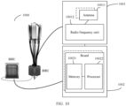
- FIG. 10 is a schematic structural diagram of a network device.
- the network device may be applied to the method shown in FIG. 3 .
- the network device 1000 includes one or more remote radio units (remote radio unit, RRU) 1001 and one or more baseband units (baseband unit, BBU) 1002.
- the RRU 1001 may be referred to as a transceiver unit, a transceiver, a transceiver circuit, a transceiver, or the like, and may include at least one antenna 10011 and a radio frequency unit 10012.
- the RRU 1001 is mainly configured to: send and receive a radio frequency signal, and perform conversion between the radio frequency signal and a baseband signal, for example, configured to send the signaling indication or the reference signal in the foregoing implementations to a terminal.
- the BBU 1002 is mainly configured to: perform baseband processing, control the network device, and so on.
- the RRU 1001 and the BBU 1002 may be physically disposed together, or may be physically separated, namely, in a distributed base station.
- the BBU 1002 is a control center of the network device, may be referred to as a processing unit, and is mainly configured to complete baseband processing functions such as channel coding, multiplexing, modulation, and spectrum spreading.
- the BBU 1002 may include one or more boards, and a plurality of boards may jointly support a radio access network (such as a 5G network) in a single access standard, or may respectively support radio access networks in different access standards.
- the BBU 1002 further includes a memory 10021 and a processor 10022.
- the memory 10021 is configured to store a necessary instruction and necessary data.
- the processor 10022 is configured to control the network device to perform a necessary action.
- the memory 10021 and the processor 10022 may serve one or more boards. In other words, a memory and a processor may be disposed on each board. Alternatively, a plurality of boards may share a same memory and processor.
- a necessary circuit is further disposed on each board.
- the network device may be configured to implement the methods in the foregoing method implementations, and details are as follows:
- the processor 10022 is configured to determine a first message, where the first message includes first offset information, or the first message includes second offset information, or the first message includes the first offset information and the second offset information; the first offset information is used to indicate a time offset value of a random access response RAR monitoring window for monitoring a RAR; and the second offset information is used to indicate a time offset value for sending a second message, and the second message is a message sent by a terminal device based on the RAR.
- the RRU 1001 is configured to send the first message.
- the first offset information and the second offset information correspond to a same indicator bit in the first message.
- the first message further includes third offset information, and the third offset information is used to indicate a time offset value for sending a feedback message of downlink data by the terminal device.
- the first message further includes fourth offset information, and the fourth offset information is used to indicate a time offset value for sending uplink data.
- the third offset information and the fourth offset information correspond to a same indicator bit in the first message.
- the RRU 1001 is further configured to: send a third message to the terminal device, where the third message includes third offset information, or the third message includes fourth offset information, or the third message includes the third offset information and the fourth offset information.
- the third offset information is used to indicate a time offset value for sending a feedback message of downlink data by the terminal device
- the fourth offset information is used to indicate a time offset value for sending uplink data.
Landscapes
- Engineering & Computer Science (AREA)
- Computer Networks & Wireless Communication (AREA)
- Signal Processing (AREA)
- Physics & Mathematics (AREA)
- Astronomy & Astrophysics (AREA)
- Aviation & Aerospace Engineering (AREA)
- General Physics & Mathematics (AREA)
- Mobile Radio Communication Systems (AREA)
- Communication Control (AREA)
- Data Exchanges In Wide-Area Networks (AREA)
Claims (15)
- Kommunikationsverfahren, umfassend:Empfangen (303) einer ersten Nachricht von einer Netzwerkvorrichtung durch eine Endgerätvorrichtung, wobei die erste Nachricht erste Versatzinformationen umfasst oder die erste Nachricht zweite Versatzinformationen umfasst oder die erste Nachricht die ersten Versatzinformationen und die zweiten Versatzinformationen umfasst, wobei die ersten Versatzinformationen verwendet werden, um einen Zeitversatzwert eines Direktzugriffsantwort(RAR)-Überwachungsfensters zum Überwachen einer RAR anzugeben, und die zweiten Versatzinformationen verwendet werden, um einen Zeitversatzwert zum Senden einer zweiten Nachricht anzugeben, und die zweite Nachricht eine Nachricht ist, die durch die Endgerätvorrichtung basierend auf der RAR gesendet wird; unddirektes Zugreifen (304) auf die Netzwerkvorrichtung basierend auf der ersten Nachricht durch die Endgerätvorrichtung,wobei die Zeitversatzwerte, die den ersten Versatzinformationen und den zweiten Versatzinformationen entsprechen, basierend auf einer Signalübertragungsdauer zwischen der Netzwerkvorrichtung und der Endgerätvorrichtung berechnet werden.
- Verfahren nach Anspruch 1, wobei die ersten Versatzinformationen und die zweiten Versatzinformationen einem gleichen Indikatorbit in der ersten Nachricht entsprechen.
- Verfahren nach Anspruch 1 oder 2, wobei die erste Nachricht ferner dritte Versatzinformationen umfasst und die dritten Versatzinformationen verwendet werden, um einen Zeitversatzwert zum Senden einer Rückmeldungsnachricht von Downlink-Daten durch die Endgerätvorrichtung anzugeben.
- Verfahren nach einem der Ansprüche 1 bis 3, wobei die erste Nachricht ferner vierte Versatzinformationen umfasst und die vierten Versatzinformationen verwendet werden, um einen Zeitversatzwert zum Senden von Uplink-Daten anzugeben.
- Verfahren nach Anspruch 4, wobei die dritten Versatzinformationen und die vierten Versatzinformationen einem gleichen Indikatorbit in der ersten Nachricht entsprechen.
- Kommunikationsverfahren, umfassend:Bestimmen (301) einer ersten Nachricht durch eine Netzwerkvorrichtung, wobei die erste Nachricht erste Versatzinformationen umfasst oder die erste Nachricht zweite Versatzinformationen umfasst oder die erste Nachricht die ersten Versatzinformationen und die zweiten Versatzinformationen umfasst, wobei die ersten Versatzinformationen verwendet werden, um einen Zeitversatzwert eines Direktzugriffsantwort(RAR)-Überwachungsfensters zum Überwachen einer RAR anzugeben, und die zweiten Versatzinformationen verwendet werden, um einen Zeitversatzwert zum Senden einer zweiten Nachricht anzugeben, und die zweite Nachricht eine Nachricht ist, die durch eine Endgerätvorrichtung basierend auf der RAR gesendet wird; undSenden (302) der ersten Nachricht durch die Netzwerkvorrichtung;wobei die Zeitversatzwerte, die den ersten Versatzinformationen und den zweiten Versatzinformationen entsprechen, basierend auf einer Signalübertragungsdauer zwischen der Netzwerkvorrichtung und der Endgerätvorrichtung berechnet werden.
- Verfahren nach Anspruch 6, wobei die ersten Versatzinformationen und die zweiten Versatzinformationen einem gleichen Indikatorbit in der ersten Nachricht entsprechen.
- Verfahren nach Anspruch 6 oder 7, wobei die erste Nachricht ferner dritte Versatzinformationen umfasst und die dritten Versatzinformationen verwendet werden, um einen Zeitversatzwert zum Senden einer Rückmeldungsnachricht von Downlink-Daten durch die Endgerätvorrichtung anzugeben.
- Verfahren nach einem der Ansprüche 6 bis 8, wobei die erste Nachricht ferner vierte Versatzinformationen umfasst und die vierten Versatzinformationen verwendet werden, um einen Zeitversatzwert zum Senden von Uplink-Daten anzugeben.
- Verfahren nach Anspruch 9, wobei die dritten Versatzinformationen und die vierten Versatzinformationen einem gleichen Indikatorbit in der ersten Nachricht entsprechen.
- Verfahren nach Anspruch 6 oder 7, ferner umfassend:Senden einer dritten Nachricht an die Endgerätvorrichtung durch die Netzwerkvorrichtung, wobei die dritte Nachricht dritte Versatzinformationen umfasst oder die dritte Nachricht vierte Versatzinformationen umfasst oder die dritte Nachricht die dritten Versatzinformationen und die vierten Versatzinformationen umfasst, wobeidie dritten Versatzinformationen verwendet werden, um einen Zeitversatzwert zum Senden einer Rückmeldungsnachricht von Downlink-Daten durch die Endgerätvorrichtung anzugeben, und die vierten Versatzinformationen verwendet werden, um einen Zeitversatzwert zum Senden von Uplink-Daten anzugeben.
- Endgerätvorrichtung, die dazu konfiguriert ist, das Verfahren nach einem der Ansprüche 1 bis 5 durchzuführen.
- Netzwerkvorrichtung, die dazu konfiguriert ist, das Verfahren nach einem der Ansprüche 6 bis 11 durchzuführen.
- Computerlesbares Speichermedium, das einen Satz Anweisungen speichert, der, wenn er durch einen Prozessor (901) einer Endgerätvorrichtung (900) ausgeführt wird, bewirkt, dass die Endgerätvorrichtung das Verfahren nach einem der Ansprüche 1 bis 5 durchführt.
- Computerlesbares Speichermedium, das einen Satz Anweisungen speichert, der, wenn er durch einen Prozessor (10022) einer Netzwerkvorrichtung (1000) ausgeführt wird, bewirkt, dass die Netzwerkvorrichtung das Verfahren nach einem der Ansprüche 6 bis 11 durchführt.
Priority Applications (1)
| Application Number | Priority Date | Filing Date | Title |
|---|---|---|---|
| EP23198274.5A EP4329217A3 (de) | 2018-04-04 | 2019-04-03 | Kommunikationsverfahren und -vorrichtung |
Applications Claiming Priority (2)
| Application Number | Priority Date | Filing Date | Title |
|---|---|---|---|
| CN201810302318.3A CN110351879B (zh) | 2018-04-04 | 2018-04-04 | 一种通信方法及装置 |
| PCT/CN2019/081351 WO2019192545A1 (zh) | 2018-04-04 | 2019-04-03 | 一种通信方法及装置 |
Related Child Applications (1)
| Application Number | Title | Priority Date | Filing Date |
|---|---|---|---|
| EP23198274.5A Division EP4329217A3 (de) | 2018-04-04 | 2019-04-03 | Kommunikationsverfahren und -vorrichtung |
Publications (3)
| Publication Number | Publication Date |
|---|---|
| EP3768028A1 EP3768028A1 (de) | 2021-01-20 |
| EP3768028A4 EP3768028A4 (de) | 2021-05-05 |
| EP3768028B1 true EP3768028B1 (de) | 2023-09-20 |
Family
ID=68100038
Family Applications (2)
| Application Number | Title | Priority Date | Filing Date |
|---|---|---|---|
| EP23198274.5A Pending EP4329217A3 (de) | 2018-04-04 | 2019-04-03 | Kommunikationsverfahren und -vorrichtung |
| EP19781900.6A Active EP3768028B1 (de) | 2018-04-04 | 2019-04-03 | Kommunikationsverfahren und -vorrichtung |
Family Applications Before (1)
| Application Number | Title | Priority Date | Filing Date |
|---|---|---|---|
| EP23198274.5A Pending EP4329217A3 (de) | 2018-04-04 | 2019-04-03 | Kommunikationsverfahren und -vorrichtung |
Country Status (6)
| Country | Link |
|---|---|
| US (1) | US20210022175A1 (de) |
| EP (2) | EP4329217A3 (de) |
| CN (2) | CN110351879B (de) |
| BR (1) | BR112020020240A2 (de) |
| WO (1) | WO2019192545A1 (de) |
| ZA (1) | ZA202006440B (de) |
Families Citing this family (9)
| Publication number | Priority date | Publication date | Assignee | Title |
|---|---|---|---|---|
| US20200351957A1 (en) * | 2019-05-03 | 2020-11-05 | Electronics And Telecommunications Research Institute | Timing synchronization method and apparatus therefor |
| CN112188383B (zh) * | 2019-06-12 | 2022-06-28 | 华为技术有限公司 | 一种随机接入的方法及装置 |
| WO2021016773A1 (zh) * | 2019-07-26 | 2021-02-04 | Oppo广东移动通信有限公司 | 监听随机接入响应的方法、终端设备、网络设备及存储介质 |
| CN112751603B (zh) * | 2019-10-29 | 2022-09-16 | 华为技术有限公司 | 用于卫星通信的方法和装置 |
| CN117880998A (zh) * | 2020-02-07 | 2024-04-12 | Oppo广东移动通信有限公司 | 信息指示方法、装置、设备、系统及存储介质 |
| JP7486338B2 (ja) * | 2020-04-20 | 2024-05-17 | キヤノンメディカルシステムズ株式会社 | 医用画像表示装置、医用画像出力装置、医用画像用媒体及び医用画像表示プログラム |
| CN114071691B (zh) * | 2020-08-07 | 2023-07-21 | 北京佰才邦技术股份有限公司 | 随机接入响应检测方法、装置、终端及基站侧设备 |
| EP4195785A4 (de) * | 2020-08-28 | 2023-10-11 | Huawei Technologies Co., Ltd. | Kommunikationsverfahren und -vorrichtung |
| KR20230069924A (ko) * | 2020-09-18 | 2023-05-19 | 퀄컴 인코포레이티드 | 랜덤 액세스에 대한 개선된 모니터링 |
Family Cites Families (22)
| Publication number | Priority date | Publication date | Assignee | Title |
|---|---|---|---|---|
| CN106851808B (zh) * | 2010-04-01 | 2020-08-18 | 太阳专利信托公司 | 终端装置和功率调节方法 |
| WO2012129723A1 (en) * | 2011-03-30 | 2012-10-04 | Telefonaktiebolaget L M Ericsson (Publ) | Methods and arrangements in a wireless communication system |
| EP2721896B1 (de) * | 2011-06-17 | 2018-08-22 | Telefonaktiebolaget LM Ericsson (publ) | Verfahren und knoten für direktzugang |
| GB2493784B (en) * | 2011-08-19 | 2016-04-20 | Sca Ipla Holdings Inc | Wireless communications system and method |
| US9515780B2 (en) * | 2011-12-23 | 2016-12-06 | Nokia Technologies Oy | Shifting HARQ feedback for cognitive-radio-based TD-LTE systems |
| CN114944853A (zh) * | 2013-01-25 | 2022-08-26 | 交互数字专利控股公司 | 用于确定资源的方法和无线发射/接收单元 |
| US8948078B2 (en) * | 2013-02-22 | 2015-02-03 | General Dynamics C4 Systems, Inc. | Apparatus and methods for relay-assisted uplink communication |
| US10624075B2 (en) * | 2013-03-16 | 2020-04-14 | Qualcomm Incorporated | Apparatus and method for scheduling delayed ACKs/NACKs in LTE cellular systems |
| US20160057783A1 (en) * | 2013-03-26 | 2016-02-25 | Nokia Solutions And Networks Oy | Mechanism for Providing Communication Resources for Random Access of a User |
| US9451639B2 (en) * | 2013-07-10 | 2016-09-20 | Samsung Electronics Co., Ltd. | Method and apparatus for coverage enhancement for a random access process |
| CN104854948B (zh) * | 2013-07-20 | 2019-04-05 | 华为技术有限公司 | 随机接入的控制方法及装置、随机接入方法及装置 |
| JP6204599B2 (ja) * | 2013-09-16 | 2017-09-27 | 華為技術有限公司Huawei Technologies Co.,Ltd. | ランダムアクセスにおいてリソースを事前決定するための方法、ユーザ機器、および基地局 |
| CN103929826B (zh) * | 2014-05-05 | 2015-11-18 | 盐城工学院 | 一种机器类通信终端自适应随机接入方法及系统 |
| US9603165B2 (en) * | 2015-01-30 | 2017-03-21 | Telefonaktiebolaget L M Ericsson (Publ) | Random-access response with analog beamforming |
| US20160270038A1 (en) * | 2015-03-11 | 2016-09-15 | Samsung Electronics Co., Ltd | Transmissions of downlink control channels for low cost ues |
| US9929834B2 (en) * | 2015-04-28 | 2018-03-27 | Qualcomm Incorporated | Low latency operation with different hybrid automatic repeat request (HARQ) timing options |
| CN107231217B (zh) * | 2016-03-25 | 2020-08-07 | 电信科学技术研究院 | 一种反馈信息的传输方法及装置 |
| KR102458067B1 (ko) * | 2016-03-30 | 2022-10-24 | 삼성전자 주식회사 | 이동 통신 시스템에서의 신호 전송 방법 및 장치 |
| CN107306452B (zh) * | 2016-04-22 | 2021-06-01 | 华为技术有限公司 | 数据传输的方法、用户设备及网络设备 |
| CN108702788B (zh) * | 2016-05-12 | 2021-01-12 | 华为技术有限公司 | 一种随机接入方法及装置 |
| CN107371273B (zh) * | 2016-05-13 | 2023-05-30 | 中兴通讯股份有限公司 | 随机接入方法、装置及用户设备 |
| EP3277042B1 (de) * | 2016-07-28 | 2022-05-25 | ASUSTek Computer Inc. | Verfahren und vorrichtung zur verbesserung der msg3-übertragung eines direktzugriffsverfahrens in einem drahtloskommunikationssystem |
-
2018
- 2018-04-04 CN CN201810302318.3A patent/CN110351879B/zh active Active
- 2018-04-04 CN CN202111359880.8A patent/CN114222374A/zh active Pending
-
2019
- 2019-04-03 WO PCT/CN2019/081351 patent/WO2019192545A1/zh unknown
- 2019-04-03 BR BR112020020240-1A patent/BR112020020240A2/pt unknown
- 2019-04-03 EP EP23198274.5A patent/EP4329217A3/de active Pending
- 2019-04-03 EP EP19781900.6A patent/EP3768028B1/de active Active
-
2020
- 2020-10-02 US US17/062,117 patent/US20210022175A1/en active Pending
- 2020-10-16 ZA ZA2020/06440A patent/ZA202006440B/en unknown
Also Published As
| Publication number | Publication date |
|---|---|
| EP4329217A3 (de) | 2024-05-22 |
| US20210022175A1 (en) | 2021-01-21 |
| EP3768028A4 (de) | 2021-05-05 |
| CN114222374A (zh) | 2022-03-22 |
| CN110351879B (zh) | 2021-11-19 |
| EP4329217A2 (de) | 2024-02-28 |
| BR112020020240A2 (pt) | 2021-01-12 |
| WO2019192545A1 (zh) | 2019-10-10 |
| EP3768028A1 (de) | 2021-01-20 |
| ZA202006440B (en) | 2022-01-26 |
| CN110351879A (zh) | 2019-10-18 |
Similar Documents
| Publication | Publication Date | Title |
|---|---|---|
| EP3768028B1 (de) | Kommunikationsverfahren und -vorrichtung | |
| US10149339B2 (en) | Base station, user equipment and methods for random access | |
| US20220174747A1 (en) | Method and apparatus for improving msg3 transmission of random access procedure in a wireless communication system | |
| US9642161B2 (en) | Cross-scheduling for random access response | |
| US11595854B2 (en) | Use of wait period to obtain on-demand system information for wireless networks | |
| US11589392B2 (en) | Methods for triggering a base station to transmit a MAC message | |
| WO2017046672A1 (en) | Random access procedure for latency reduction | |
| JP7282182B2 (ja) | Ra-rnti処理方法及び装置 | |
| US10791501B2 (en) | Anchor base station, slave cell and user equipment | |
| WO2020248944A1 (zh) | 一种随机接入方法及装置 | |
| CN112544118A (zh) | 用于随机接入的方法、设备和计算机可读介质 | |
| JP6940593B2 (ja) | NB−IoTをサポートするランダムアクセス手順 | |
| WO2024092618A1 (en) | Method and apparatus for ntn coverage enhancement for pucch and pusch | |
| WO2024092636A1 (en) | Method and apparatus for ntn coverage enhancement with pusch dmrs bundling |
Legal Events
| Date | Code | Title | Description |
|---|---|---|---|
| STAA | Information on the status of an ep patent application or granted ep patent |
Free format text: STATUS: THE INTERNATIONAL PUBLICATION HAS BEEN MADE |
|
| PUAI | Public reference made under article 153(3) epc to a published international application that has entered the european phase |
Free format text: ORIGINAL CODE: 0009012 |
|
| STAA | Information on the status of an ep patent application or granted ep patent |
Free format text: STATUS: REQUEST FOR EXAMINATION WAS MADE |
|
| 17P | Request for examination filed |
Effective date: 20201012 |
|
| AK | Designated contracting states |
Kind code of ref document: A1 Designated state(s): AL AT BE BG CH CY CZ DE DK EE ES FI FR GB GR HR HU IE IS IT LI LT LU LV MC MK MT NL NO PL PT RO RS SE SI SK SM TR |
|
| AX | Request for extension of the european patent |
Extension state: BA ME |
|
| A4 | Supplementary search report drawn up and despatched |
Effective date: 20210407 |
|
| RIC1 | Information provided on ipc code assigned before grant |
Ipc: H04W 74/00 20090101AFI20210330BHEP Ipc: H04W 74/08 20090101ALI20210330BHEP Ipc: H04W 84/06 20090101ALN20210330BHEP Ipc: H04B 7/185 20060101ALN20210330BHEP |
|
| DAV | Request for validation of the european patent (deleted) | ||
| DAX | Request for extension of the european patent (deleted) | ||
| REG | Reference to a national code |
Ref country code: DE Ref legal event code: R079 Ref document number: 602019037889 Country of ref document: DE Free format text: PREVIOUS MAIN CLASS: H04W0074080000 Ipc: H04W0074000000 Ref country code: DE Ref legal event code: R079 Free format text: PREVIOUS MAIN CLASS: H04W0074080000 Ipc: H04W0074000000 |
|
| GRAP | Despatch of communication of intention to grant a patent |
Free format text: ORIGINAL CODE: EPIDOSNIGR1 |
|
| STAA | Information on the status of an ep patent application or granted ep patent |
Free format text: STATUS: GRANT OF PATENT IS INTENDED |
|
| RIC1 | Information provided on ipc code assigned before grant |
Ipc: H04W 74/08 20090101ALN20230310BHEP Ipc: H04W 84/06 20090101ALN20230310BHEP Ipc: H04B 7/185 20060101ALI20230310BHEP Ipc: H04W 56/00 20090101ALI20230310BHEP Ipc: H04W 74/00 20090101AFI20230310BHEP |
|
| INTG | Intention to grant announced |
Effective date: 20230404 |
|
| P01 | Opt-out of the competence of the unified patent court (upc) registered |
Effective date: 20230514 |
|
| GRAS | Grant fee paid |
Free format text: ORIGINAL CODE: EPIDOSNIGR3 |
|
| GRAA | (expected) grant |
Free format text: ORIGINAL CODE: 0009210 |
|
| STAA | Information on the status of an ep patent application or granted ep patent |
Free format text: STATUS: THE PATENT HAS BEEN GRANTED |
|
| AK | Designated contracting states |
Kind code of ref document: B1 Designated state(s): AL AT BE BG CH CY CZ DE DK EE ES FI FR GB GR HR HU IE IS IT LI LT LU LV MC MK MT NL NO PL PT RO RS SE SI SK SM TR |
|
| REG | Reference to a national code |
Ref country code: GB Ref legal event code: FG4D |
|
| REG | Reference to a national code |
Ref country code: CH Ref legal event code: EP |
|
| REG | Reference to a national code |
Ref country code: IE Ref legal event code: FG4D |
|
| REG | Reference to a national code |
Ref country code: DE Ref legal event code: R096 Ref document number: 602019037889 Country of ref document: DE |
|
| REG | Reference to a national code |
Ref country code: LT Ref legal event code: MG9D |
|
| PG25 | Lapsed in a contracting state [announced via postgrant information from national office to epo] |
Ref country code: GR Free format text: LAPSE BECAUSE OF FAILURE TO SUBMIT A TRANSLATION OF THE DESCRIPTION OR TO PAY THE FEE WITHIN THE PRESCRIBED TIME-LIMIT Effective date: 20231221 |
|
| REG | Reference to a national code |
Ref country code: NL Ref legal event code: MP Effective date: 20230920 |
|
| PG25 | Lapsed in a contracting state [announced via postgrant information from national office to epo] |
Ref country code: SE Free format text: LAPSE BECAUSE OF FAILURE TO SUBMIT A TRANSLATION OF THE DESCRIPTION OR TO PAY THE FEE WITHIN THE PRESCRIBED TIME-LIMIT Effective date: 20230920 Ref country code: RS Free format text: LAPSE BECAUSE OF FAILURE TO SUBMIT A TRANSLATION OF THE DESCRIPTION OR TO PAY THE FEE WITHIN THE PRESCRIBED TIME-LIMIT Effective date: 20230920 Ref country code: NO Free format text: LAPSE BECAUSE OF FAILURE TO SUBMIT A TRANSLATION OF THE DESCRIPTION OR TO PAY THE FEE WITHIN THE PRESCRIBED TIME-LIMIT Effective date: 20231220 Ref country code: LV Free format text: LAPSE BECAUSE OF FAILURE TO SUBMIT A TRANSLATION OF THE DESCRIPTION OR TO PAY THE FEE WITHIN THE PRESCRIBED TIME-LIMIT Effective date: 20230920 Ref country code: LT Free format text: LAPSE BECAUSE OF FAILURE TO SUBMIT A TRANSLATION OF THE DESCRIPTION OR TO PAY THE FEE WITHIN THE PRESCRIBED TIME-LIMIT Effective date: 20230920 Ref country code: HR Free format text: LAPSE BECAUSE OF FAILURE TO SUBMIT A TRANSLATION OF THE DESCRIPTION OR TO PAY THE FEE WITHIN THE PRESCRIBED TIME-LIMIT Effective date: 20230920 Ref country code: GR Free format text: LAPSE BECAUSE OF FAILURE TO SUBMIT A TRANSLATION OF THE DESCRIPTION OR TO PAY THE FEE WITHIN THE PRESCRIBED TIME-LIMIT Effective date: 20231221 Ref country code: FI Free format text: LAPSE BECAUSE OF FAILURE TO SUBMIT A TRANSLATION OF THE DESCRIPTION OR TO PAY THE FEE WITHIN THE PRESCRIBED TIME-LIMIT Effective date: 20230920 |
|
| REG | Reference to a national code |
Ref country code: AT Ref legal event code: MK05 Ref document number: 1614410 Country of ref document: AT Kind code of ref document: T Effective date: 20230920 |
|
| PG25 | Lapsed in a contracting state [announced via postgrant information from national office to epo] |
Ref country code: NL Free format text: LAPSE BECAUSE OF FAILURE TO SUBMIT A TRANSLATION OF THE DESCRIPTION OR TO PAY THE FEE WITHIN THE PRESCRIBED TIME-LIMIT Effective date: 20230920 |
|
| PG25 | Lapsed in a contracting state [announced via postgrant information from national office to epo] |
Ref country code: IS Free format text: LAPSE BECAUSE OF FAILURE TO SUBMIT A TRANSLATION OF THE DESCRIPTION OR TO PAY THE FEE WITHIN THE PRESCRIBED TIME-LIMIT Effective date: 20240120 |
|
| PG25 | Lapsed in a contracting state [announced via postgrant information from national office to epo] |
Ref country code: AT Free format text: LAPSE BECAUSE OF FAILURE TO SUBMIT A TRANSLATION OF THE DESCRIPTION OR TO PAY THE FEE WITHIN THE PRESCRIBED TIME-LIMIT Effective date: 20230920 |
|
| PG25 | Lapsed in a contracting state [announced via postgrant information from national office to epo] |
Ref country code: ES Free format text: LAPSE BECAUSE OF FAILURE TO SUBMIT A TRANSLATION OF THE DESCRIPTION OR TO PAY THE FEE WITHIN THE PRESCRIBED TIME-LIMIT Effective date: 20230920 |
|
| PG25 | Lapsed in a contracting state [announced via postgrant information from national office to epo] |
Ref country code: SM Free format text: LAPSE BECAUSE OF FAILURE TO SUBMIT A TRANSLATION OF THE DESCRIPTION OR TO PAY THE FEE WITHIN THE PRESCRIBED TIME-LIMIT Effective date: 20230920 Ref country code: RO Free format text: LAPSE BECAUSE OF FAILURE TO SUBMIT A TRANSLATION OF THE DESCRIPTION OR TO PAY THE FEE WITHIN THE PRESCRIBED TIME-LIMIT Effective date: 20230920 Ref country code: IS Free format text: LAPSE BECAUSE OF FAILURE TO SUBMIT A TRANSLATION OF THE DESCRIPTION OR TO PAY THE FEE WITHIN THE PRESCRIBED TIME-LIMIT Effective date: 20240120 Ref country code: ES Free format text: LAPSE BECAUSE OF FAILURE TO SUBMIT A TRANSLATION OF THE DESCRIPTION OR TO PAY THE FEE WITHIN THE PRESCRIBED TIME-LIMIT Effective date: 20230920 Ref country code: EE Free format text: LAPSE BECAUSE OF FAILURE TO SUBMIT A TRANSLATION OF THE DESCRIPTION OR TO PAY THE FEE WITHIN THE PRESCRIBED TIME-LIMIT Effective date: 20230920 Ref country code: CZ Free format text: LAPSE BECAUSE OF FAILURE TO SUBMIT A TRANSLATION OF THE DESCRIPTION OR TO PAY THE FEE WITHIN THE PRESCRIBED TIME-LIMIT Effective date: 20230920 Ref country code: AT Free format text: LAPSE BECAUSE OF FAILURE TO SUBMIT A TRANSLATION OF THE DESCRIPTION OR TO PAY THE FEE WITHIN THE PRESCRIBED TIME-LIMIT Effective date: 20230920 Ref country code: PT Free format text: LAPSE BECAUSE OF FAILURE TO SUBMIT A TRANSLATION OF THE DESCRIPTION OR TO PAY THE FEE WITHIN THE PRESCRIBED TIME-LIMIT Effective date: 20240122 Ref country code: SK Free format text: LAPSE BECAUSE OF FAILURE TO SUBMIT A TRANSLATION OF THE DESCRIPTION OR TO PAY THE FEE WITHIN THE PRESCRIBED TIME-LIMIT Effective date: 20230920 |
|
| PGFP | Annual fee paid to national office [announced via postgrant information from national office to epo] |
Ref country code: GB Payment date: 20240229 Year of fee payment: 6 |