EP3768023B1 - Data transmission method and terminal - Google Patents
Data transmission method and terminal Download PDFInfo
- Publication number
- EP3768023B1 EP3768023B1 EP20194585.4A EP20194585A EP3768023B1 EP 3768023 B1 EP3768023 B1 EP 3768023B1 EP 20194585 A EP20194585 A EP 20194585A EP 3768023 B1 EP3768023 B1 EP 3768023B1
- Authority
- EP
- European Patent Office
- Prior art keywords
- data
- time
- time resource
- terminal
- sps
- Prior art date
- Legal status (The legal status is an assumption and is not a legal conclusion. Google has not performed a legal analysis and makes no representation as to the accuracy of the status listed.)
- Active
Links
- 230000005540 biological transmission Effects 0.000 title claims description 47
- 238000000034 method Methods 0.000 title claims description 36
- 238000004891 communication Methods 0.000 claims description 67
- 239000008186 active pharmaceutical agent Substances 0.000 claims 14
- 230000011664 signaling Effects 0.000 description 19
- 238000010586 diagram Methods 0.000 description 18
- 230000015654 memory Effects 0.000 description 15
- 238000012545 processing Methods 0.000 description 15
- 208000037918 transfusion-transmitted disease Diseases 0.000 description 12
- 230000008569 process Effects 0.000 description 9
- 238000005516 engineering process Methods 0.000 description 8
- 230000006870 function Effects 0.000 description 7
- 238000004904 shortening Methods 0.000 description 6
- 230000008878 coupling Effects 0.000 description 3
- 238000010168 coupling process Methods 0.000 description 3
- 238000005859 coupling reaction Methods 0.000 description 3
- 230000007246 mechanism Effects 0.000 description 3
- 230000008901 benefit Effects 0.000 description 2
- 230000001934 delay Effects 0.000 description 2
- 238000011161 development Methods 0.000 description 2
- VJYFKVYYMZPMAB-UHFFFAOYSA-N ethoprophos Chemical compound CCCSP(=O)(OCC)SCCC VJYFKVYYMZPMAB-UHFFFAOYSA-N 0.000 description 2
- 238000011160 research Methods 0.000 description 2
- 238000001228 spectrum Methods 0.000 description 2
- 230000001413 cellular effect Effects 0.000 description 1
- 230000001419 dependent effect Effects 0.000 description 1
- 238000013461 design Methods 0.000 description 1
- 230000000977 initiatory effect Effects 0.000 description 1
- 230000007774 longterm Effects 0.000 description 1
- 238000010295 mobile communication Methods 0.000 description 1
- 230000003287 optical effect Effects 0.000 description 1
- 230000009467 reduction Effects 0.000 description 1
- 230000003068 static effect Effects 0.000 description 1
- 230000001360 synchronised effect Effects 0.000 description 1
Images


Classifications
-
- H—ELECTRICITY
- H04—ELECTRIC COMMUNICATION TECHNIQUE
- H04L—TRANSMISSION OF DIGITAL INFORMATION, e.g. TELEGRAPHIC COMMUNICATION
- H04L5/00—Arrangements affording multiple use of the transmission path
- H04L5/003—Arrangements for allocating sub-channels of the transmission path
- H04L5/0053—Allocation of signaling, i.e. of overhead other than pilot signals
-
- H—ELECTRICITY
- H04—ELECTRIC COMMUNICATION TECHNIQUE
- H04W—WIRELESS COMMUNICATION NETWORKS
- H04W72/00—Local resource management
- H04W72/02—Selection of wireless resources by user or terminal
-
- H—ELECTRICITY
- H04—ELECTRIC COMMUNICATION TECHNIQUE
- H04W—WIRELESS COMMUNICATION NETWORKS
- H04W72/00—Local resource management
- H04W72/04—Wireless resource allocation
- H04W72/044—Wireless resource allocation based on the type of the allocated resource
- H04W72/0446—Resources in time domain, e.g. slots or frames
-
- H—ELECTRICITY
- H04—ELECTRIC COMMUNICATION TECHNIQUE
- H04W—WIRELESS COMMUNICATION NETWORKS
- H04W72/00—Local resource management
- H04W72/12—Wireless traffic scheduling
-
- H—ELECTRICITY
- H04—ELECTRIC COMMUNICATION TECHNIQUE
- H04W—WIRELESS COMMUNICATION NETWORKS
- H04W72/00—Local resource management
- H04W72/12—Wireless traffic scheduling
- H04W72/1263—Mapping of traffic onto schedule, e.g. scheduled allocation or multiplexing of flows
- H04W72/1268—Mapping of traffic onto schedule, e.g. scheduled allocation or multiplexing of flows of uplink data flows
-
- H—ELECTRICITY
- H04—ELECTRIC COMMUNICATION TECHNIQUE
- H04W—WIRELESS COMMUNICATION NETWORKS
- H04W72/00—Local resource management
- H04W72/20—Control channels or signalling for resource management
- H04W72/21—Control channels or signalling for resource management in the uplink direction of a wireless link, i.e. towards the network
-
- H—ELECTRICITY
- H04—ELECTRIC COMMUNICATION TECHNIQUE
- H04W—WIRELESS COMMUNICATION NETWORKS
- H04W72/00—Local resource management
- H04W72/20—Control channels or signalling for resource management
- H04W72/23—Control channels or signalling for resource management in the downlink direction of a wireless link, i.e. towards a terminal
-
- H—ELECTRICITY
- H04—ELECTRIC COMMUNICATION TECHNIQUE
- H04W—WIRELESS COMMUNICATION NETWORKS
- H04W72/00—Local resource management
- H04W72/20—Control channels or signalling for resource management
Definitions
- Embodiments of the disclosure relate to the field of communications, and more particularly to a data communication method, a terminal and a non-transitory computer-readable storage medium.
- an end-to-end transmission delay of real-time remote computing for mobile terminals is required to be shorter than 10ms
- a transmission delay of traffic efficiency and safety is required to be shorter than 5ms
- another service may require a shorter transmission delay.
- TTI Transmission Time Interval
- LTE-A Rel-13 LTE-Advanced Release 13
- a short TTI has the advantage of shortening of the transmission delay, however, at the corresponding cost of high control signaling overhead and low spectrum efficiency.
- resources may be wasted.
- the terminal may be dynamically scheduled to use different TTI lengths, that is, a short TTI is used for transmission of a short-delay service, and a conventional TTI is used when another service is transmitted. Therefore, LTE-A Rel-13 makes such a requirement that compatibility with the existing LTE system should be ensured on a carrier supporting short-TTI transmission, that is, compatibility with a 1ms TTI is required.
- an LTE system supports two different data scheduling manners, i.e., semi-persistent scheduling (SPS) and dynamic scheduling (DS), where SPS means that a base station indicates terminals scheduling information through high-layer signaling, including: a scheduling period, a physical resource location and a modulation and scheduling level, and after the base station sends Downlink Control Information (DCI) to the terminal to trigger the terminal for SPS, the terminal performs data communication on the same frequency resource at a fixed interval.
- DCI Downlink Control Information
- DS means that whenever the base station determines to perform a burst of data communication, the base station sends a piece of DCI to the terminal, and the terminal performs data communication on a corresponding time-frequency resource according to an indication of the DCI, where DS has no fixed period.
- DS and SPS correspond to the same TTI.
- time-frequency resources corresponding to DS and SPS are overlapped, since DS and SPS correspond to the same TTI, data incoming time, base station scheduling time, data processing time and the like corresponding to DS and SPS are all the same, a terminal may merge original SPS data and DS data together for communication. For example, the terminal merges all of the data for communication on the time-frequency resource corresponding to DS. That is, in an SPS transmission subframe, if the terminal receives DS, the DS data is received or sent (the base station packs the SPS data into the DS data).
- a first aspect provides a data communication method, comprising: communicating, by a terminal, first semi-persistent scheduling, SPS, data on first time resource within a time unit, wherein the time unit is a time slot, the first time resource is not overlapped with a second time resource within the time unit, the second time resource is configured for the terminal to communicate second dynamic scheduling, DS, data, the first data is transmitted at a transmission time interval, TTI, smaller than or equal to a length of the time unit, and the second data is transmitted at a TTI smaller than or equal to the length of the time unit.
- a second aspect provides a data communication method, comprising: communicating, by a terminal, first semi-persistent scheduling, SPS, data on first time resource within a time unit, but not transmitting second dynamic scheduling, DS, data, wherein the time unit is a time slot, the first time resource is overlapped with a second time resource within the time unit, the second time resource is configured for the terminal to communicate the second DS data, the first data is transmitted at a transmission time interval, TTI, smaller than or equal to a length of the time unit, and the second data is transmitted at a TTI smaller than or equal to the length of the time unit.
- a third aspect provides a terminal, comprising: a transceiver, configured to communicate first semi-persistent scheduling, SPS, data on first time resource within a time unit, wherein the time unit is a time slot, the first time resource is not overlapped with a second time resource within the time unit, the second time resource is configured for the terminal to communicate second dynamic scheduling, DS, data, the first data is transmitted at a transmission time interval, TTI, smaller than or equal to a length of the time unit, and the second data is transmitted at a TTI smaller than or equal to the length of the time unit.
- a fourth aspect provides a terminal, comprising: a transceiver, configured to communicate first semi-persistent scheduling, SPS, data on first time resource within a time unit, but not transmit second dynamic scheduling, DS, data, wherein the time unit is a time slot, the first time resource is overlapped with a second time resource within the time unit, the second time resource is configured for the terminal to communicate the second DS data, the first data is transmitted at a transmission time interval, TTI, smaller than or equal to a length of the time unit, and the second data is transmitted at a TTI smaller than or equal to the length of the time unit.
- TTI transmission time interval
- the terminal supports communication with different TTIs
- the base station indicates the terminal to communicate the first SPS data at the first TTI and communicate the second DS data at the second TTI on the target time unit of the target carrier
- at least one of the first data or the second data is determined to be communicated according to the respective locations of the first time resource occupied for SPS transmission and the second time resource occupied for DS transmission in the target time unit, so that DS and SPS under different TTIs are implemented.
- a part may be, but not limited to, a process running on a processor, the processor, an object, an executable file, an execution thread, a program and/or a computer. It is graphically represented that all applications running on computing equipment and the computing equipment may be parts. One or more parts may reside in a process and/or an execution thread, and the parts may be located on a computer and/or distributed between two or more computers. In addition, these parts may be executed from various computer-readable media on which various data structures are stored.
- the parts may communicate through local and/or remote processes according to, for example, signals with one or more data groups (for example, data from two parts interacting with each other in a local system, a distributed system and/or a network, for example, the Internet interacting with another system through a signal).
- data groups for example, data from two parts interacting with each other in a local system, a distributed system and/or a network, for example, the Internet interacting with another system through a signal.
- GSM Global System of Mobile Communication
- CDMA Code Division Multiple Access
- WCDMA Wideband CDMA
- GPRS General Packet Radio Service
- LTE LTE
- FDD Frequency Division Duplex
- TDD Time Division Duplex
- UMTS Universal Mobile Telecommunication System
- WiMAX Worldwide Interoperability for Microwave Access
- the terminal may communicate with one or more core networks through a Radio Access Network (RAN), and the terminal may refer to User Equipment (UE), an access terminal, a user unit, a subscriber station, a mobile radio station, a mobile station, a remote station, a remote terminal, mobile equipment, a user terminal, a terminal, wireless communication equipment, a user agent or a user device.
- RAN Radio Access Network
- UE User Equipment
- the access terminal may be a cellular telephone, a cordless telephone, a Session Initiation Protocol (SIP) telephone, a Wireless Local Loop (WLL) station, a Personal Digital Assistant (PDA), handheld equipment with a wireless communication function, computing equipment, or other processing equipment connected to a wireless modem, vehicle-mounted equipment, wearable equipment, a terminal in a future 5G network and the like.
- SIP Session Initiation Protocol
- WLL Wireless Local Loop
- PDA Personal Digital Assistant
- the base station may be equipment configured to communicate with the terminal, and for example, may be a Base Transceiver Station (BTS) in a GSM or CDMA, may also be a NodeB (NB) in a WCDMA system, and may further be an Evolutional Node B (eNB or eNodeB) in an LTE system.
- BTS Base Transceiver Station
- NB NodeB
- eNB Evolutional Node B
- the base station may be a relay station, an access point, vehicle-mounted equipment, wearable equipment, network-side equipment in the future 5G network and the like.
- Typical transmission delays for Downlink (DL) transmission in Release 8 (Rel 8) and Release 9 (Rel 9) of an LTE system are listed in Table 1.
- Delays generated by processes incoming data and data decoding in UE are mainly related to a length of a TTI. Therefore, one of key technologies for reducing the transmission delay is shortening the TTI.
- the length of a TTI is 1ms, and LTE-A Rel-13 has determined to start making researches on data transmission with a shorter TTI.
- a short TTI has the advantage of shortening of the transmission delay, however, at the corresponding cost of high control signaling overhead and low spectrum efficiency.
- resources may be wasted.
- the terminal may be dynamically scheduled to use different TTI lengths, that is, a short TTI is used for transmission of a short-delay service, and a conventional TTI is used when another service is transmitted. Therefore, LTE-A Rel-13 makes such a requirement that compatibility with the existing LTE system should be ensured on a carrier supporting short-TTI transmission, that is, compatibility with a 1ms TTI is required.
- an LTE system supports two different data scheduling manners, i.e., Semi-Persistent Scheduling (SPS) and dynamic scheduling (DS), where SPS means that a base station indicates terminals scheduling information through high-layer signaling, including: a scheduling period, a physical resource location and a modulation and scheduling level, and after the base station sends Downlink Control Information (DCI) to the terminal to trigger the terminal for SPS, the terminal performs data communication on the same frequency resource at a fixed interval.
- SPS Semi-Persistent Scheduling
- DS dynamic scheduling
- DS means that whenever the base station determines to perform a burst of data communication, the base station sends a piece of DCI to the terminal, and the terminal performs data communication on a corresponding time-frequency resource according to an indication of the DCI, where DS has no fixed period.
- DS and SPS correspond to the same TTI.
- time-frequency resources corresponding to DS and SPS are overlapped, since DS and SPS correspond to the same TTI, data incoming time, base station scheduling time, data processing time and the like corresponding to DS and SPS are all the same, a terminal may merge original SPS data and DS data together for communication. For example, the terminal merges all of the data for communication on the time-frequency resource corresponding to DS. That is, in an SPS transmission subframe, if the terminal receives DS, the DS data is received or sent (the base station packs the SPS data into the DS data).
- the embodiments of the disclosure provide a mechanism to implement data communication in the LTE system when DS and SPS correspond to different TTIs.
- a time unit may be a frame, a subframe, a timeslot or a symbol.
- the time unit may be a subframe.
- a target time unit is called as a target subframe.
- FIG. 1 illustrates a data communication method 100 according to the disclosure.
- the method 100 includes the following operations.
- a terminal receives first indication signaling sent by a base station.
- the first indication signaling indicates the terminal to communicate first SPS data at a first TTI on a target time unit of a target carrier.
- the terminal receives second indication signaling sent by the base station.
- the second indication signaling indicates the terminal to communicate second DS data at a second TTI on the target time unit of the target carrier.
- a length of the first TTI is unequal to a length of the second TTI, moreover, the length of the first TTI is smaller than or equal to a length of the time unit, and the length of the second TTI is smaller than or equal to the length of the time unit.
- the terminal determines a location of a first time resource occupied by SPS transmission in the target time unit and a location of a second time resource occupied by DS transmission in the target time unit.
- the terminal determines to communicate at least one of the first data or the second data according to the location of the first time resource in the target time unit and the location of the second time resource in the target time unit.
- the terminal executing the method 100 may support communication with TTIs of different lengths.
- the base station sends the first indication signaling to the terminal, the first indication signaling indicating the terminal to perform SPS.
- the terminal performs data communication on the same frequency resource at a fixed interval. Therefore, the terminal performs SPS data communication on some time-frequency resources at fixed locations.
- one of these fixed time-frequency resources, in the frequency domain corresponds to the target carrier, and in the time domain, corresponds to a target subframe.
- the terminal occupies the first time resource in the target subframe to communicate the first SPS data at the first TTI on the target subframe of the target carrier.
- the first indication signaling is DCI
- the first DCI includes information indicative of the target carrier and the target subframe.
- the terminal determines the specific location of the first time resource occupied by SPS transmission in the target subframe.
- the base station sends the second indication signaling to the terminal, the second indication signaling indicating the terminal to communicate the second DS data at the second TTI on the target subframe of the target carrier.
- the terminal receives the second indication signaling of the base station.
- the indication signaling is DCI
- the DCI includes information indicative of the target carrier and the target subframe.
- the terminal determines the location of the second time resource occupied by DS transmission in the target subframe.
- the length of the first TTI is unequal to the length of the second TTI, moreover, the length of the first TTI is smaller than or equal to the length of the time unit (the subframe), and the length of the second TTI is smaller than or equal to the length of the time unit (the subframe).
- the terminal controls communication of the first data and the second data, or, in other words, determines to communicate at least one of the first data or the second data according to the location of the first time resource occupied by the first SPS data in the target subframe and the location of the second time resource occupied by the second DS data in the target subframe.
- communication of the first SPS data includes sending of a first SPS scheduling PUSCH, and here, the first SPS PUSCH is called as an SPS-PUSCH for short.
- Communication of the second DS data includes sending of a second DS PUSCH, and here, the second DS PUSCH is called as a dyn-PUSCH.
- communication of the first SPS data includes reception of a first SPS PDSCH, and here, the first SPS PDSCH is called as an SPS-PDSCH for short.
- Communication of the second DS data includes reception of a second DS PDSCH, and here, the second DS PDSCH is called as a dyn-PDSCH for short.
- the terminal supports communication with different TTIs
- the base station indicates the terminal to communicate the first SPS data at the first TTI and communicate the second DS data at the second TTI on the target time unit of the target carrier
- at least one of the first data or the second data is determined to be communicated according to the respective locations of the first time resource occupied for SPS transmission and the second time resource occupied for DS transmission in the target time unit, so that DS and SPS at different TTIs are implemented.
- the target subframe may include time resources occupied to transmit PDCCHs and time resources occupied to transmit data, and both the first time resource and the second time resource belong to time resources occupied to transmit data.
- the length of the first TTI is 1ms, and the length of the second TTI is smaller than 1ms.
- the operation that the terminal determines to communicate at least one of the first data or the second data according to the location of the first time resource in the target time unit and the location of the second time resource in the target time unit in S140 includes that: when the first time resource and the second time resource are overlapped in the target time unit, the terminal determines only to occupy the first time resource to communicate the first data.
- a schematic diagram of data communication according to the embodiment is illustrated in FIG. 2 .
- the length of the first TTI is 1ms (that is, an existing TTI is adopted for communication of the SPS-PUSCH/SPS-PDSCH), and the SPS-PUSCH/SPS-PDSCH is specifically communicated on the first time resource.
- the base station dynamically schedules the terminal to occupy the second time resource to communicate the dyn-PUSCH/dyn-PDSCH at the second TTI (the length of the second TTI is smaller than 1ms) in the target subframe of the target carrier.
- the terminal determines the locations of the first time resource and the second time resource. When the first time resource and the second time resource are overlapped in the target subframe, the terminal only occupies the first time resource to communicate the SPS-PUSCH/SPS-PDSCH, and does not communicate the dyn-PUSCH/dyn-PDSCH.
- the length of the first TTI is 1ms, and the length of the second TTI is smaller than 1ms.
- the operation that the terminal determines to communicate at least one of the first data or the second data according to the location of the first time resource in the target time unit and the location of the second time resource in the target time unit in S140 includes that: when the first time resource and the second time resource are overlapped in the target time unit and a starting time location of the first time resource is the same as a starting time location of the second time resource, the terminal determines only to occupy the second time resource to communicate the second data.
- the starting time location of the second time resource may only be the same as the starting time location of the first time resource or after the starting time location of the first time resource.
- the condition that the starting time location of the first time resource is the same as the starting time location of the second time resource is discussed in this embodiment.
- a schematic diagram of data communication according to the embodiment is illustrated in FIG. 3 .
- the length of the first TTI is 1ms (that is, the existing TTI is adopted for communication of the SPS-PUSCH/SPS-PDSCH), and the SPS-PUSCH/SPS-PDSCH is specifically communicated on the first time resource.
- the base station dynamically schedules the terminal to occupy the second time resource to communicate the dyn-PUSCH/dyn-PDSCH at the second TTI (the length of the second TTI is smaller than 1ms) in the target subframe of the target carrier.
- the terminal determines the locations of the first time resource and the second time resource.
- the terminal When the starting time location of the second time resource is the same as the starting time location of the time resource occupied for data communication and the first time resource and the second time resource are overlapped in the target subframe, the terminal only occupies the second time resource to communicate the dyn-PUSCH/dyn-PDSCH, and does not communicate the SPS-PUSCH/SPS-PDSCH.
- the length of the first TTI is 1ms, and the length of the second TTI is smaller than 1ms.
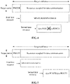
- the operation that the terminal determines to communicate at least one of the first data or the second data according to the location of the first time resource in the target time unit and the location of the second time resource in the target time unit in S140 includes that: when the first time resource and the second time resource are overlapped in the target time unit and the starting time location of the second time resource is after the starting time location of the first time resource, the terminal determines only to occupy the first time resource to communicate the first data.
- a schematic diagram of data communication according to the disclosure is illustrated in FIG. 4 .
- the length of the first TTI is 1ms (that is, the existing TTI is adopted for communication of the SPS-PUSCH/SPS-PDSCH), and the SPS-PUSCH/SPS-PDSCH is specifically communicated on the first time resource.
- the base station dynamically schedules the terminal to occupy the second time resource to communicate the dyn-PUSCH/dyn-PDSCH at the second TTI (the length of the second TTI is smaller than 1ms) in the target subframe of the target carrier.
- the terminal determines the locations of the first time resource and the second time resource.
- the terminal When the starting time location of the second time resource is after the starting time location of the time resource occupied for data communication and the first time resource and the second time resource are overlapped in the target subframe, the terminal only occupies the first time resource to communicate the SPS-PUSCH/SPS-PDSCH, and does not communicate the dyn-PUSCH/dyn-PDSCH.
- the length of the first TTI is smaller than 1ms, and the length of the second TTI is smaller than 1ms.
- the operation that the terminal determines to communicate at least one of the first data or the second data according to the location of the first time resource in the target time unit and the location of the second time resource in the target time unit in S140 includes that: when the first time resource and the second time resource are not overlapped in the target time unit, the terminal determines to occupy the first time resource to communicate the first data and occupy the second time resource to communicate the second data.
- a schematic diagram of data communication according to the disclosure is illustrated in FIG. 5 .
- the length of the first TTI is 1ms
- the SPS-PUSCH/SPS-PDSCH is specifically communicated on the first time resource.
- the base station dynamically schedules the terminal to occupy the second time resource to communicate the dyn-PUSCH/dyn-PDSCH at the second TTI (the length of the second TTI is smaller than 1ms) on the target subframe of the target carrier.
- the terminal determines the locations of the first time resource and the second time resource.
- the terminal occupies the first time resource to communicate the SPS-PUSCH/SPS-PDSCH, and the terminal occupies the second time resource to communicate the dyn-PUSCH/dyn-PDSCH.
- the length of the first TTI is smaller than 1ms, and the length of the second TTI is smaller than 1ms.
- the operation that the terminal determines to communicate at least one of the first data or the second data according to the location of the first time resource in the target time unit and the location of the second time resource in the target time unit in S140 includes that: when the first time resource and the second time resource are overlapped in the target time unit, the terminal determines only to occupy the first time resource to communicate the first data.
- a schematic diagram of data communication according to the disclosure is illustrated in FIG. 6 .
- the length of the first TTI is smaller than 1ms, and the SPS-PUSCH/SPS-PDSCH is specifically communicated on the first time resource.
- the base station dynamically schedules the terminal to occupy the second time resource to communicate the dyn-PUSCH/dyn-PDSCH at the second TTI (the length of the second TTI is smaller than 1ms) in the target subframe of the target carrier.
- the terminal determines the locations of the first time resource and the second time resource. When the first time resource and the second time resource are overlapped in the target subframe, the terminal only occupies the first time resource to communicate theSPS-PUSCH/SPS-PDSCH, and does not communicate the dyn-PUSCH/dyn-PDSCH.
- the length of the first TTI is smaller than 1ms
- the length of the second TTI is smaller than 1ms.
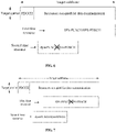
- the operation that the terminal determines to communicate at least one of the first data or the second data according to the location of the first time resource in the target time unit and the location of the second time resource in the target time unit in S140 includes that: when the first time resource and the second time resource are overlapped in the target time unit and the starting time location of the first time resource is after the starting time location of the second time resource, the terminal determines only to occupy the second time resource to communicate the second data.
- a schematic diagram of data communication according to the disclosure is illustrated in FIG. 7 .
- the length of the first TTI is smaller than 1ms, and the SPS-PUSCH/SPS-PDSCH is specifically communicated on the first time resource.
- the base station dynamically schedules the terminal to occupy the second time resource to communicate the dyn-PUSCH/dyn-PDSCH at the second TTI (the length of the second TTI is smaller than 1ms) in the target subframe of the target carrier.
- the terminal determines the locations of the first time resource and the second time resource.
- the terminal When the first time resource and the second time resource are overlapped in the target subframe and the starting time location of the first time resource is after the starting time location of the second time resource, the terminal only occupies the second time resource to communicate the dyn-PUSCH/dyn-PDSCH, and does not communicate the SPS-PUSCH/SPS-PDSCH.
- the length of the first TTI is smaller than 1ms, and the length of the second TTI is smaller than 1ms.
- the operation that the terminal determines to communicate at least one of the first data or the second data according to the location of the first time resource in the target time unit and the location of the second time resource in the target time unit in S140 includes that: when the first time resource and the second time resource are overlapped in the target time unit and the starting time location of the second time resource is after the starting time location of the first time resource, the terminal determines only to occupy the first time resource to communicate the first data.
- FIG. 8 A schematic diagram of data communication according to the disclosure is illustrated in FIG. 8 .
- the length of the first TTI is smaller than 1ms, and the SPS-PUSCH/SPS-PDSCH is specifically communicated on the first time resource.
- the base station dynamically schedules the terminal to occupy the second time resource to communicate the dyn-PUSCH/dyn-PDSCH at the second TTI (the length of the second TTI is smaller than 1ms) in the target subframe of the target carrier.
- the terminal determines the locations of the first time resource and the second time resource.
- the terminal When the first time resource and the second time resource are overlapped in the target subframe and the starting time location of the second time resource is after the starting time location of the first time resource, the terminal only occupies the first time resource to communicate the SPS-PUSCH/SPS-PDSCH, and does not communicate the dyn-PUSCH/dyn-PDSCH.
- FIG. 9 illustrates a schematic block diagram of a terminal 200 according to the disclosure.
- the terminal 200 includes a receiving module 210 and a processing module 220.
- the receiving module 210 may be configured to receive first indication signaling sent by a base station, the first indication signaling indicating the terminal to communicate first SPS data at a first TTI on a target time unit of a target carrier.
- the receiving module 210 may be further configured to receive second indication signaling sent by the base station, the second indication signaling indicating the terminal to communicate second DS data at a second TTI on the target time unit of the target carrier, where a length of the first TTI is unequal to a length of the second TTI, the length of the first TTI is smaller than or equal to a length of the time unit, and the length of the second TTI is smaller than or equal to the length of the time unit.
- the processing module 220 may be configured to determine a location of a first time resource occupied by SPS transmission in the target time unit and a location of a second time resource occupied by DS transmission in the target time unit.
- the processing module 220 may further be configured to determine to communicate at least one of the first data or the second data according to the location of the first time resource in the target time unit and the location of the second time resource in the target time unit.
- the terminal supports communication at different TTIs
- the base station indicates the terminal to communicate the first SPS data at the first TTI and communicate the second DS data at the second TTI on the target time unit of the target carrier, and at least one of the first data or the second data is determined to be communicated according to the respective locations of the first time resource occupied for SPS transmission and the second time resource occupied for DS transmission in the target time unit, so that DS and SPS at respective different TTIs are implemented.
- communication of the first SPS data includes sending of a first SPS scheduling PUSCH, and communication of the second DS data includes sending of a second DS PUSCH; or communication of the first SPS data includes reception of a first SPS PDSCH, and communication of the second DS data includes reception of a second DS PDSCH.
- the time unit may be a subframe
- the processing module 220 may specifically be configured to, when the first time resource and the second time resource are overlapped in the target time unit, determine, by the terminal, only to occupy the first time resource to communicate the first data.
- the processing module 220 may specifically be configured to, when the first time resource and the second time resource are overlapped in the target time unit and a starting time location of the first time resource is the same as a starting time location of the second time resource or the starting time location of the first time resource is after the starting time location of the second time resource, determine, by the terminal, only to occupy the second time resource to communicate the second data.
- the processing module 220 may specifically be configured to, when the first time resource and the second time resource are overlapped in the target time unit and the starting time location of the second time resource is after the starting time location of the first time resource, determine, by the terminal, only to occupy the first time resource to communicate the first data.
- the processing module 220 may specifically be configured to, when the first time resource and the second time resource are not overlapped in the target time unit, determine, by the terminal, to occupy the first time resource to communicate the first data and occupy the second time resource to communicate the second data.
- a terminal 300 may include a processor 310, a transceiver 320 and a memory 330, wherein the memory 330 may be configured to store a code executed by the processor 310 and the like.
- the components in the terminal 300 are coupled together through a bus system 340, where the bus system 340 includes a data bus, and further includes a power bus, a control bus and a state signal bus.
- the bus system 340 includes a data bus, and further includes a power bus, a control bus and a state signal bus.
- the terminal 200 illustrated in FIG. 9 and the terminal 300 illustrated in FIG. 10 may implement each process implemented in the disclosure in FIG. 1 to FIG. 8 , which will not be elaborated herein to avoid repetition.
- the method of the disclosure may be applied to a processor or implemented by the processor.
- the processor may be an integrated circuit chip with a signal processing capability. In an implementation process, each step of the method embodiments may be completed by an integrated logical circuit of hardware in the processor or an instruction in a software form.
- the processor may be a universal processor, a Digital Signal Processor (DSP), an Application Specific Integrated Circuit (ASIC), a Field Programmable Gate Array (FPGA) or another programmable logical device, discrete gate or transistor logical device and discrete hardware component.
- DSP Digital Signal Processor
- ASIC Application Specific Integrated Circuit
- FPGA Field Programmable Gate Array
- Each method, step and logical block diagram disclosed in the embodiments of the disclosure may be implemented or executed.
- the universal processor may be a microprocessor or the processor may also be any conventional processor and the like.
- the operations of the method disclosed in combination with the embodiments of the disclosure may be directly embodied to be executed and completed by a hardware decoding processor or executed and completed by a combination of hardware and software modules in the decoding processor.
- the software module may be located in a mature storage medium in this field such as a Random Access Memory (RAM), a flash memory, a Read-Only Memory (ROM), a Programmable ROM (PROM) or Electrically Erasable PROM (EEPROM) and a register.
- RAM Random Access Memory
- ROM Read-Only Memory
- PROM Electrically Erasable PROM
- the storage medium is located in a memory, and the processor reads information in the memory, and completes the operations of the methods in combination with hardware.
- the memory in the disclosure may be a volatile memory or a nonvolatile memory, or may include both the volatile and nonvolatile memories, wherein the nonvolatile memory may be a ROM, a PROM, an Erasable PROM (EPROM), an EEPROM or a flash memory.
- the volatile memory may be a RAM, and is used as an external high-speed cache.
- RAMs in various forms may be adopted, such as a Static RAM (SRAM), a Dynamic RAM (DRAM), a Synchronous DRAM (SDRAM), a Double Data Rate SDRAM (DDRSDRAM), an Enhanced SDRAM (ESDRAM), a Synchlink DRAM (SLDRAM) and a Direct Rambus RAM (DR RAM).
- SRAM Static RAM
- DRAM Dynamic RAM
- SDRAM Synchronous DRAM
- DDRSDRAM Double Data Rate SDRAM
- ESDRAM Enhanced SDRAM
- SLDRAM Synchlink DRAM
- DR RAM Direct Rambus RAM
- the disclosed system, device and method may be implemented in another manner.
- the device embodiment described above is only schematic, and for example, division of the units is only logic function division, and other division manners may be adopted during practical implementation.
- multiple units or components may be combined or integrated into another system, or some characteristics may be neglected or not executed.
- coupling or direct coupling or communication connection between each displayed or discussed component may be indirect coupling or communication connection, implemented through some interfaces, of the device or the units, and may be electrical and mechanical or adopt other forms.
- the units described as separate parts may or may not be physically separated, and parts displayed as units may or may not be physical units, and namely may be located in the same place, or may also be distributed to multiple network units. Part or all of the units may be selected to achieve the purpose of the solutions of the embodiments according to a practical requirement.
- each function unit in each embodiment of the disclosure may be integrated into a processing unit, each unit may also exist independently, and two or more than two unit may also be integrated into a unit.
- the function When being implemented in form of software function unit and sold or used as an independent product, the function may also be stored in a computer-readable storage medium.
- the technical solutions of the disclosure substantially or parts making contributions to a conventional art or part of the technical solutions may be embodied in form of software product, and the computer software product is stored in a storage medium, including a plurality of instructions configured to enable a piece of computer equipment (which may be a personal computer, a server, network equipment or the like) to execute all or part of the operations of the method in each embodiment of the disclosure.
- the abovementioned storage medium includes: various media capable of storing program codes such as a U disk, a mobile hard disk, a ROM, a RAM, a magnetic disk or an optical disk.
Description
- Embodiments of the disclosure relate to the field of communications, and more particularly to a data communication method, a terminal and a non-transitory computer-readable storage medium.
- Along with development of an air interface technology and continuous extension of applications thereof, reducing a transmission delay becomes one of key communication indexes in a future communication technology. For example, an end-to-end transmission delay of real-time remote computing for mobile terminals is required to be shorter than 10ms, a transmission delay of traffic efficiency and safety is required to be shorter than 5ms, and another service may require a shorter transmission delay.
- One of key technologies for reducing a transmission delay is shortening a Transmission Time Interval (TTI). At present, the length of a TTI of the Long Term Evolution (LTE) system is 1ms, and LTE-Advanced Release 13 (LTE-A Rel-13) has determined to start making researches on data transmission with a shorter TTI.
- A short TTI has the advantage of shortening of the transmission delay, however, at the corresponding cost of high control signaling overhead and low spectrum efficiency. For a terminal with multiple types of services running concurrently, if a unified TTI is determined according to the service with a minimum delay requirement, resources may be wasted. For ensuring the transmission delay and simultaneously considering system efficiency, the terminal may be dynamically scheduled to use different TTI lengths, that is, a short TTI is used for transmission of a short-delay service, and a conventional TTI is used when another service is transmitted. Therefore, LTE-A Rel-13 makes such a requirement that compatibility with the existing LTE system should be ensured on a carrier supporting short-TTI transmission, that is, compatibility with a 1ms TTI is required.
- At present, an LTE system supports two different data scheduling manners, i.e., semi-persistent scheduling (SPS) and dynamic scheduling (DS), where SPS means that a base station indicates terminals scheduling information through high-layer signaling, including: a scheduling period, a physical resource location and a modulation and scheduling level, and after the base station sends Downlink Control Information (DCI) to the terminal to trigger the terminal for SPS, the terminal performs data communication on the same frequency resource at a fixed interval. DS means that whenever the base station determines to perform a burst of data communication, the base station sends a piece of DCI to the terminal, and the terminal performs data communication on a corresponding time-frequency resource according to an indication of the DCI, where DS has no fixed period.
- In a system not supporting a short TTI, DS and SPS correspond to the same TTI. When time-frequency resources corresponding to DS and SPS are overlapped, since DS and SPS correspond to the same TTI, data incoming time, base station scheduling time, data processing time and the like corresponding to DS and SPS are all the same, a terminal may merge original SPS data and DS data together for communication. For example, the terminal merges all of the data for communication on the time-frequency resource corresponding to DS. That is, in an SPS transmission subframe, if the terminal receives DS, the DS data is received or sent (the base station packs the SPS data into the DS data).
- However, when DS and SPS of the LTE system correspond to different TTIs, different data incoming time, base station scheduling time and data processing time corresponding to the scheduling make an existing working mechanism with SPS overridden by DS not applicable anymore.
- Related technologies are known from ALCATEL-LUCENT SHANGHAI BELL ET AL: "Overview of Specification Impact for TTI Shortening", 3GPP DRAFT; R1-156721 OVERVIEW OF SPECIFICATION IMPACT FOR TTI SHORTENING FINAL, 3RD GENERATION PARTNERSHIP PROJECT (3GPP), MOBILE COMPETENCE CENTRE; 650, ROUTE DES LUCIOLES; F-06921 SOPHIA-ANTIPOLI, vol. RAN WG1, no. Anaheim, US; 20141115 -20141122 15 November 2015 (2015-11-15)"; 3rd Generation Partnership Project; Technical Specification Group Radio Access Network; Evolved Universal Terrestrial Radio Access (E-UTRA); Study on latency reduction techniques for L TE (Release 13)", 3GPP STANDARD; TECHNICAL REPORT; 3GPP TR 36.881, 3RD GENERATION PARTNERSHIP PROJECT (3GPP), MOBILE COMPETENCE CENTRE; 650, ROUTE DES LUCIOLES; F-06921 SOPHIA-ANTIPOLIS CEDEX; FRANCE, vol. RAN WG2, no. V0.5.0, 4 December 2015 (2015-12-04), pages 1-86;
US8503380B2 ; andUS2012/0155416 A1 . - The present invention is defined in the independent claims. Any embodiment or aspect or example in the present disclosure that does not fall within the scope of the present invention does not form part of the invention.
- According to the present invention, data communication methods as set forth in claims 1 and 4, terminals as set forth in claims 5 and 8 and non-transitory computer-readable storage medium as set forth in claim 9 are provided. Embodiments of the invention are claimed in the dependent claims.
- A first aspect provides a data communication method, comprising: communicating, by a terminal, first semi-persistent scheduling, SPS, data on first time resource within a time unit, wherein the time unit is a time slot, the first time resource is not overlapped with a second time resource within the time unit, the second time resource is configured for the terminal to communicate second dynamic scheduling, DS, data, the first data is transmitted at a transmission time interval, TTI, smaller than or equal to a length of the time unit, and the second data is transmitted at a TTI smaller than or equal to the length of the time unit.
- A second aspect provides a data communication method, comprising: communicating, by a terminal, first semi-persistent scheduling, SPS, data on first time resource within a time unit, but not transmitting second dynamic scheduling, DS, data, wherein the time unit is a time slot, the first time resource is overlapped with a second time resource within the time unit, the second time resource is configured for the terminal to communicate the second DS data, the first data is transmitted at a transmission time interval, TTI, smaller than or equal to a length of the time unit, and the second data is transmitted at a TTI smaller than or equal to the length of the time unit.
- A third aspect provides a terminal, comprising: a transceiver, configured to communicate first semi-persistent scheduling, SPS, data on first time resource within a time unit, wherein the time unit is a time slot, the first time resource is not overlapped with a second time resource within the time unit, the second time resource is configured for the terminal to communicate second dynamic scheduling, DS, data, the first data is transmitted at a transmission time interval, TTI, smaller than or equal to a length of the time unit, and the second data is transmitted at a TTI smaller than or equal to the length of the time unit.
- A fourth aspect provides a terminal, comprising: a transceiver, configured to communicate first semi-persistent scheduling, SPS, data on first time resource within a time unit, but not transmit second dynamic scheduling, DS, data, wherein the time unit is a time slot, the first time resource is overlapped with a second time resource within the time unit, the second time resource is configured for the terminal to communicate the second DS data, the first data is transmitted at a transmission time interval, TTI, smaller than or equal to a length of the time unit, and the second data is transmitted at a TTI smaller than or equal to the length of the time unit.
- According to the data communication method and terminal of the embodiments of the disclosure, the terminal supports communication with different TTIs, the base station indicates the terminal to communicate the first SPS data at the first TTI and communicate the second DS data at the second TTI on the target time unit of the target carrier, and at least one of the first data or the second data is determined to be communicated according to the respective locations of the first time resource occupied for SPS transmission and the second time resource occupied for DS transmission in the target time unit, so that DS and SPS under different TTIs are implemented.
- In order to describe the technical solutions of the embodiments of the disclosure more clearly, the drawings required to be used in the embodiments or a conventional art will be simply introduced below. Obviously, the drawings described below are only some embodiments of the disclosure. Other drawings may further be obtained by those skilled in the art according to these drawings without creative work.
-
FIG. 1 illustrates a schematic flowchart of a data communication method according to the disclosure. -
FIG. 2 illustrates a schematic diagram of data communication according to the disclosure. -
FIG. 3 illustrates a schematic diagram of data communication according to the disclosure. -
FIG. 4 illustrates a schematic diagram of data communication according to the disclosure. -
FIG. 5 illustrates a schematic diagram of data communication according to the disclosure. -
FIG. 6 illustrates a schematic diagram of data communication according to the disclosure. -
FIG. 7 illustrates a schematic diagram of data communication according to the disclosure. -
FIG. 8 illustrates a schematic diagram of data communication according to the disclosure. -
FIG. 9 illustrates a schematic block diagram of a terminal according to the disclosure. -
FIG. 10 illustrates a schematic block diagram of a terminal according to the disclosure. - Terms "part", "module", "system" and the like used in the specification are adopted to represent an entity, hardware, firmware, combination of hardware and software, software or software in execution related to a computer. For example, a part may be, but not limited to, a process running on a processor, the processor, an object, an executable file, an execution thread, a program and/or a computer. It is graphically represented that all applications running on computing equipment and the computing equipment may be parts. One or more parts may reside in a process and/or an execution thread, and the parts may be located on a computer and/or distributed between two or more computers. In addition, these parts may be executed from various computer-readable media on which various data structures are stored. The parts may communicate through local and/or remote processes according to, for example, signals with one or more data groups (for example, data from two parts interacting with each other in a local system, a distributed system and/or a network, for example, the Internet interacting with another system through a signal).
- It is to be understood that the technical solutions of the embodiments of the disclosure may be applied to various communication systems, for example: a Global System of Mobile Communication (GSM), a Code Division Multiple Access (CDMA) system, a Wideband CDMA (WCDMA) General Packet Radio Service (GPRS) system, an LTE system, an LTE Frequency Division Duplex (FDD) system, LTE Time Division Duplex (TDD), a Universal Mobile Telecommunication System (UMTS), a Worldwide Interoperability for Microwave Access (WiMAX) communication system and a future 5th-Generation (5G) communication system.
- Various embodiments are described in the disclosure in combination with a terminal. The terminal may communicate with one or more core networks through a Radio Access Network (RAN), and the terminal may refer to User Equipment (UE), an access terminal, a user unit, a subscriber station, a mobile radio station, a mobile station, a remote station, a remote terminal, mobile equipment, a user terminal, a terminal, wireless communication equipment, a user agent or a user device. The access terminal may be a cellular telephone, a cordless telephone, a Session Initiation Protocol (SIP) telephone, a Wireless Local Loop (WLL) station, a Personal Digital Assistant (PDA), handheld equipment with a wireless communication function, computing equipment, or other processing equipment connected to a wireless modem, vehicle-mounted equipment, wearable equipment, a terminal in a future 5G network and the like.
- Various embodiments are described in the disclosure in combination with a base station. The base station may be equipment configured to communicate with the terminal, and for example, may be a Base Transceiver Station (BTS) in a GSM or CDMA, may also be a NodeB (NB) in a WCDMA system, and may further be an Evolutional Node B (eNB or eNodeB) in an LTE system. Or, the base station may be a relay station, an access point, vehicle-mounted equipment, wearable equipment, network-side equipment in the future 5G network and the like.
- Related technologies and concepts involved in the embodiments of the disclosure will be briefly introduced below.
- Along with development of an air interface technology and continuous extension of applications thereof, reducing a transmission delay becomes one of key communication indexes in future communication technologies. For example, an end-to-end transmission delay of real-time remote computing for mobile terminals is required to be shorter than 10ms, a transmission delay of traffic efficiency and safety is required to be shorter than 5ms, and another service may require a shorter transmission delay. Typical transmission delays for Downlink (DL) transmission in Release 8 (Rel 8) and Release 9 (Rel 9) of an LTE system are listed in Table 1.
Table 1 Sequence number Descriptions Duration (ms) 1 Processes incoming data 3 2 TTI alignment 0.5 3 Transmission of DL data 1 4 Data decoding in UE 3 Total delay 7.5 - Delays generated by processes incoming data and data decoding in UE are mainly related to a length of a TTI. Therefore, one of key technologies for reducing the transmission delay is shortening the TTI. At present, in the LTE system, the length of a TTI is 1ms, and LTE-A Rel-13 has determined to start making researches on data transmission with a shorter TTI.
- A short TTI has the advantage of shortening of the transmission delay, however, at the corresponding cost of high control signaling overhead and low spectrum efficiency. For a terminal with multiple types of services running concurrently, if a unified TTI is determined according to the service with a minimum delay requirement, resources may be wasted. For ensuring the transmission delay and simultaneously considering system efficiency, the terminal may be dynamically scheduled to use different TTI lengths, that is, a short TTI is used for transmission of a short-delay service, and a conventional TTI is used when another service is transmitted. Therefore, LTE-A Rel-13 makes such a requirement that compatibility with the existing LTE system should be ensured on a carrier supporting short-TTI transmission, that is, compatibility with a 1ms TTI is required.
- At present, an LTE system supports two different data scheduling manners, i.e., Semi-Persistent Scheduling (SPS) and dynamic scheduling (DS), where SPS means that a base station indicates terminals scheduling information through high-layer signaling, including: a scheduling period, a physical resource location and a modulation and scheduling level, and after the base station sends Downlink Control Information (DCI) to the terminal to trigger the terminal for SPS, the terminal performs data communication on the same frequency resource at a fixed interval. DS means that whenever the base station determines to perform a burst of data communication, the base station sends a piece of DCI to the terminal, and the terminal performs data communication on a corresponding time-frequency resource according to an indication of the DCI, where DS has no fixed period.
- In a system not supporting a short TTI, DS and SPS correspond to the same TTI. When time-frequency resources corresponding to DS and SPS are overlapped, since DS and SPS correspond to the same TTI, data incoming time, base station scheduling time, data processing time and the like corresponding to DS and SPS are all the same, a terminal may merge original SPS data and DS data together for communication. For example, the terminal merges all of the data for communication on the time-frequency resource corresponding to DS. That is, in an SPS transmission subframe, if the terminal receives DS, the DS data is received or sent (the base station packs the SPS data into the DS data).
- However, when DS and SPS of the LTE system correspond to different TTIs, different data incoming time, base station scheduling time and data processing time corresponding to the scheduling make an existing working mechanism with SPS overridden by DS not applicable anymore.
- On the basis of the problem, the embodiments of the disclosure provide a mechanism to implement data communication in the LTE system when DS and SPS correspond to different TTIs.
- In the disclosure, a time unit may be a frame, a subframe, a timeslot or a symbol.
- Preferably, the time unit may be a subframe. For convenience, descriptions will be made by taking a subframe as an example in the disclosure, and a target time unit is called as a target subframe.
-
FIG. 1 illustrates adata communication method 100 according to the disclosure. Themethod 100 includes the following operations. - In S110, a terminal receives first indication signaling sent by a base station. The first indication signaling indicates the terminal to communicate first SPS data at a first TTI on a target time unit of a target carrier.
- In S120, the terminal receives second indication signaling sent by the base station. The second indication signaling indicates the terminal to communicate second DS data at a second TTI on the target time unit of the target carrier. Here, a length of the first TTI is unequal to a length of the second TTI, moreover, the length of the first TTI is smaller than or equal to a length of the time unit, and the length of the second TTI is smaller than or equal to the length of the time unit.
- In S130, the terminal determines a location of a first time resource occupied by SPS transmission in the target time unit and a location of a second time resource occupied by DS transmission in the target time unit.
- In S140, the terminal determines to communicate at least one of the first data or the second data according to the location of the first time resource in the target time unit and the location of the second time resource in the target time unit.
- Herein, the terminal executing the
method 100 may support communication with TTIs of different lengths. In terms of SPS, the base station sends the first indication signaling to the terminal, the first indication signaling indicating the terminal to perform SPS. During SPS, the terminal performs data communication on the same frequency resource at a fixed interval. Therefore, the terminal performs SPS data communication on some time-frequency resources at fixed locations. In the embodiments of the disclosure, one of these fixed time-frequency resources, in the frequency domain, corresponds to the target carrier, and in the time domain, corresponds to a target subframe. The terminal occupies the first time resource in the target subframe to communicate the first SPS data at the first TTI on the target subframe of the target carrier. Preferably, the first indication signaling is DCI, and the first DCI includes information indicative of the target carrier and the target subframe. The terminal determines the specific location of the first time resource occupied by SPS transmission in the target subframe. - In terms of DS, the base station sends the second indication signaling to the terminal, the second indication signaling indicating the terminal to communicate the second DS data at the second TTI on the target subframe of the target carrier. Correspondingly, the terminal receives the second indication signaling of the base station. Preferably, the indication signaling is DCI, and the DCI includes information indicative of the target carrier and the target subframe. The terminal determines the location of the second time resource occupied by DS transmission in the target subframe.
- Here, the length of the first TTI is unequal to the length of the second TTI, moreover, the length of the first TTI is smaller than or equal to the length of the time unit (the subframe), and the length of the second TTI is smaller than or equal to the length of the time unit (the subframe).
- The terminal controls communication of the first data and the second data, or, in other words, determines to communicate at least one of the first data or the second data according to the location of the first time resource occupied by the first SPS data in the target subframe and the location of the second time resource occupied by the second DS data in the target subframe.
- Specifically, communication of the first SPS data includes sending of a first SPS scheduling PUSCH, and here, the first SPS PUSCH is called as an SPS-PUSCH for short. Communication of the second DS data includes sending of a second DS PUSCH, and here, the second DS PUSCH is called as a dyn-PUSCH.
- Or, in another condition, communication of the first SPS data includes reception of a first SPS PDSCH, and here, the first SPS PDSCH is called as an SPS-PDSCH for short. Communication of the second DS data includes reception of a second DS PDSCH, and here, the second DS PDSCH is called as a dyn-PDSCH for short.
- According to the data communication method of the embodiment of the disclosure, the terminal supports communication with different TTIs, the base station indicates the terminal to communicate the first SPS data at the first TTI and communicate the second DS data at the second TTI on the target time unit of the target carrier, and at least one of the first data or the second data is determined to be communicated according to the respective locations of the first time resource occupied for SPS transmission and the second time resource occupied for DS transmission in the target time unit, so that DS and SPS at different TTIs are implemented.
- In the disclosure, the target subframe may include time resources occupied to transmit PDCCHs and time resources occupied to transmit data, and both the first time resource and the second time resource belong to time resources occupied to transmit data.
- In an embodiment of the disclosure, the length of the first TTI is 1ms, and the length of the second TTI is smaller than 1ms. The operation that the terminal determines to communicate at least one of the first data or the second data according to the location of the first time resource in the target time unit and the location of the second time resource in the target time unit in S140 includes that: when the first time resource and the second time resource are overlapped in the target time unit, the terminal determines only to occupy the first time resource to communicate the first data. A schematic diagram of data communication according to the embodiment is illustrated in
FIG. 2 . - In the disclosure, as illustrated in
FIG. 2 , in the target subframe of the target carrier, the length of the first TTI is 1ms (that is, an existing TTI is adopted for communication of the SPS-PUSCH/SPS-PDSCH), and the SPS-PUSCH/SPS-PDSCH is specifically communicated on the first time resource. The base station dynamically schedules the terminal to occupy the second time resource to communicate the dyn-PUSCH/dyn-PDSCH at the second TTI (the length of the second TTI is smaller than 1ms) in the target subframe of the target carrier. The terminal determines the locations of the first time resource and the second time resource. When the first time resource and the second time resource are overlapped in the target subframe, the terminal only occupies the first time resource to communicate the SPS-PUSCH/SPS-PDSCH, and does not communicate the dyn-PUSCH/dyn-PDSCH. - In another embodiment of the disclosure, the length of the first TTI is 1ms, and the length of the second TTI is smaller than 1ms. The operation that the terminal determines to communicate at least one of the first data or the second data according to the location of the first time resource in the target time unit and the location of the second time resource in the target time unit in S140 includes that: when the first time resource and the second time resource are overlapped in the target time unit and a starting time location of the first time resource is the same as a starting time location of the second time resource, the terminal determines only to occupy the second time resource to communicate the second data.
- It is to be understood that, when the length of the first TTI is 1ms and the length of the second TTI is smaller than 1ms, the starting time location of the second time resource may only be the same as the starting time location of the first time resource or after the starting time location of the first time resource. The condition that the starting time location of the first time resource is the same as the starting time location of the second time resource is discussed in this embodiment. A schematic diagram of data communication according to the embodiment is illustrated in
FIG. 3 . - In the disclosure, as illustrated in
FIG. 3 , in the target subframe of the target carrier, the length of the first TTI is 1ms (that is, the existing TTI is adopted for communication of the SPS-PUSCH/SPS-PDSCH), and the SPS-PUSCH/SPS-PDSCH is specifically communicated on the first time resource. The base station dynamically schedules the terminal to occupy the second time resource to communicate the dyn-PUSCH/dyn-PDSCH at the second TTI (the length of the second TTI is smaller than 1ms) in the target subframe of the target carrier. The terminal determines the locations of the first time resource and the second time resource. When the starting time location of the second time resource is the same as the starting time location of the time resource occupied for data communication and the first time resource and the second time resource are overlapped in the target subframe, the terminal only occupies the second time resource to communicate the dyn-PUSCH/dyn-PDSCH, and does not communicate the SPS-PUSCH/SPS-PDSCH. - In the embodiment, the length of the first TTI is 1ms, and the length of the second TTI is smaller than 1ms. The operation that the terminal determines to communicate at least one of the first data or the second data according to the location of the first time resource in the target time unit and the location of the second time resource in the target time unit in S140 includes that: when the first time resource and the second time resource are overlapped in the target time unit and the starting time location of the second time resource is after the starting time location of the first time resource, the terminal determines only to occupy the first time resource to communicate the first data. A schematic diagram of data communication according to the disclosure is illustrated in
FIG. 4 . - In the disclosure, as illustrated in
FIG. 4 , in the target subframe of the target carrier, the length of the first TTI is 1ms (that is, the existing TTI is adopted for communication of the SPS-PUSCH/SPS-PDSCH), and the SPS-PUSCH/SPS-PDSCH is specifically communicated on the first time resource. The base station dynamically schedules the terminal to occupy the second time resource to communicate the dyn-PUSCH/dyn-PDSCH at the second TTI (the length of the second TTI is smaller than 1ms) in the target subframe of the target carrier. The terminal determines the locations of the first time resource and the second time resource. When the starting time location of the second time resource is after the starting time location of the time resource occupied for data communication and the first time resource and the second time resource are overlapped in the target subframe, the terminal only occupies the first time resource to communicate the SPS-PUSCH/SPS-PDSCH, and does not communicate the dyn-PUSCH/dyn-PDSCH. - It is to be understood that the schemes corresponding to
FIG. 3 andFIG. 4 respectively may be combined into a scheme. - In another embodiment of the disclosure, the length of the first TTI is smaller than 1ms, and the length of the second TTI is smaller than 1ms. The operation that the terminal determines to communicate at least one of the first data or the second data according to the location of the first time resource in the target time unit and the location of the second time resource in the target time unit in S140 includes that: when the first time resource and the second time resource are not overlapped in the target time unit, the terminal determines to occupy the first time resource to communicate the first data and occupy the second time resource to communicate the second data. A schematic diagram of data communication according to the disclosure is illustrated in
FIG. 5 . - In the disclosure, as illustrated in
FIG. 5 , on the target subframe of the target carrier, the length of the first TTI is 1ms, and the SPS-PUSCH/SPS-PDSCH is specifically communicated on the first time resource. The base station dynamically schedules the terminal to occupy the second time resource to communicate the dyn-PUSCH/dyn-PDSCH at the second TTI (the length of the second TTI is smaller than 1ms) on the target subframe of the target carrier. The terminal determines the locations of the first time resource and the second time resource. When the first time resource and the second time resource are not overlapped in the target subframe, the terminal occupies the first time resource to communicate the SPS-PUSCH/SPS-PDSCH, and the terminal occupies the second time resource to communicate the dyn-PUSCH/dyn-PDSCH. - In another embodiment of the disclosure, the length of the first TTI is smaller than 1ms, and the length of the second TTI is smaller than 1ms. The operation that the terminal determines to communicate at least one of the first data or the second data according to the location of the first time resource in the target time unit and the location of the second time resource in the target time unit in S140 includes that: when the first time resource and the second time resource are overlapped in the target time unit, the terminal determines only to occupy the first time resource to communicate the first data. A schematic diagram of data communication according to the disclosure is illustrated in
FIG. 6 . - In the disclosure, as illustrated in
FIG. 6 , in the target subframe of the target carrier, the length of the first TTI is smaller than 1ms, and the SPS-PUSCH/SPS-PDSCH is specifically communicated on the first time resource. The base station dynamically schedules the terminal to occupy the second time resource to communicate the dyn-PUSCH/dyn-PDSCH at the second TTI (the length of the second TTI is smaller than 1ms) in the target subframe of the target carrier. The terminal determines the locations of the first time resource and the second time resource. When the first time resource and the second time resource are overlapped in the target subframe, the terminal only occupies the first time resource to communicate theSPS-PUSCH/SPS-PDSCH, and does not communicate the dyn-PUSCH/dyn-PDSCH. - It is to be understood that the schemes corresponding to
FIG. 5 andFIG. 6 respectively may be combined into a scheme. - In another embodiment of the disclosure, the length of the first TTI is smaller than 1ms, and the length of the second TTI is smaller than 1ms. The operation that the terminal determines to communicate at least one of the first data or the second data according to the location of the first time resource in the target time unit and the location of the second time resource in the target time unit in S140 includes that: when the first time resource and the second time resource are overlapped in the target time unit and the starting time location of the first time resource is after the starting time location of the second time resource, the terminal determines only to occupy the second time resource to communicate the second data. A schematic diagram of data communication according to the disclosure is illustrated in
FIG. 7 . - In the disclosure, as illustrated in
FIG. 7 , in the target subframe of the target carrier, the length of the first TTI is smaller than 1ms, and the SPS-PUSCH/SPS-PDSCH is specifically communicated on the first time resource. The base station dynamically schedules the terminal to occupy the second time resource to communicate the dyn-PUSCH/dyn-PDSCH at the second TTI (the length of the second TTI is smaller than 1ms) in the target subframe of the target carrier. The terminal determines the locations of the first time resource and the second time resource. When the first time resource and the second time resource are overlapped in the target subframe and the starting time location of the first time resource is after the starting time location of the second time resource, the terminal only occupies the second time resource to communicate the dyn-PUSCH/dyn-PDSCH, and does not communicate the SPS-PUSCH/SPS-PDSCH. - In another embodiment of the disclosure, the length of the first TTI is smaller than 1ms, and the length of the second TTI is smaller than 1ms. The operation that the terminal determines to communicate at least one of the first data or the second data according to the location of the first time resource in the target time unit and the location of the second time resource in the target time unit in S140 includes that: when the first time resource and the second time resource are overlapped in the target time unit and the starting time location of the second time resource is after the starting time location of the first time resource, the terminal determines only to occupy the first time resource to communicate the first data. A schematic diagram of data communication according to the disclosure is illustrated in
FIG. 8 . - In the disclosure, as illustrated in
FIG. 8 , in the target subframe of the target carrier, the length of the first TTI is smaller than 1ms, and the SPS-PUSCH/SPS-PDSCH is specifically communicated on the first time resource. The base station dynamically schedules the terminal to occupy the second time resource to communicate the dyn-PUSCH/dyn-PDSCH at the second TTI (the length of the second TTI is smaller than 1ms) in the target subframe of the target carrier. The terminal determines the locations of the first time resource and the second time resource. When the first time resource and the second time resource are overlapped in the target subframe and the starting time location of the second time resource is after the starting time location of the first time resource, the terminal only occupies the first time resource to communicate the SPS-PUSCH/SPS-PDSCH, and does not communicate the dyn-PUSCH/dyn-PDSCH. - It is to be understood that the schemes corresponding to
FIG. 7 andFIG. 8 respectively may be combined into a scheme. - It is also to be understood that the schemes corresponding to
FIG. 5 ,FIG. 7 andFIG. 8 respectively may be combined into a scheme. -
FIG. 9 illustrates a schematic block diagram of a terminal 200 according to the disclosure. The terminal 200 includes a receivingmodule 210 and aprocessing module 220. - The receiving
module 210 may be configured to receive first indication signaling sent by a base station, the first indication signaling indicating the terminal to communicate first SPS data at a first TTI on a target time unit of a target carrier. - The receiving
module 210 may be further configured to receive second indication signaling sent by the base station, the second indication signaling indicating the terminal to communicate second DS data at a second TTI on the target time unit of the target carrier, where a length of the first TTI is unequal to a length of the second TTI, the length of the first TTI is smaller than or equal to a length of the time unit, and the length of the second TTI is smaller than or equal to the length of the time unit. - The
processing module 220 may be configured to determine a location of a first time resource occupied by SPS transmission in the target time unit and a location of a second time resource occupied by DS transmission in the target time unit. - The
processing module 220 may further be configured to determine to communicate at least one of the first data or the second data according to the location of the first time resource in the target time unit and the location of the second time resource in the target time unit. - In the disclosure, the terminal supports communication at different TTIs, the base station indicates the terminal to communicate the first SPS data at the first TTI and communicate the second DS data at the second TTI on the target time unit of the target carrier, and at least one of the first data or the second data is determined to be communicated according to the respective locations of the first time resource occupied for SPS transmission and the second time resource occupied for DS transmission in the target time unit, so that DS and SPS at respective different TTIs are implemented.
- Alternatively, in an embodiment, communication of the first SPS data includes sending of a first SPS scheduling PUSCH, and communication of the second DS data includes sending of a second DS PUSCH; or communication of the first SPS data includes reception of a first SPS PDSCH, and communication of the second DS data includes reception of a second DS PDSCH.
- In the disclosure, the time unit may be a subframe
- Alternatively, the
processing module 220 may specifically be configured to, when the first time resource and the second time resource are overlapped in the target time unit, determine, by the terminal, only to occupy the first time resource to communicate the first data. - Alternatively, the
processing module 220 may specifically be configured to, when the first time resource and the second time resource are overlapped in the target time unit and a starting time location of the first time resource is the same as a starting time location of the second time resource or the starting time location of the first time resource is after the starting time location of the second time resource, determine, by the terminal, only to occupy the second time resource to communicate the second data. - Alternatively, the
processing module 220 may specifically be configured to, when the first time resource and the second time resource are overlapped in the target time unit and the starting time location of the second time resource is after the starting time location of the first time resource, determine, by the terminal, only to occupy the first time resource to communicate the first data. - Alternatively, the
processing module 220 may specifically be configured to, when the first time resource and the second time resource are not overlapped in the target time unit, determine, by the terminal, to occupy the first time resource to communicate the first data and occupy the second time resource to communicate the second data. - It is to be noted that, in the disclosure, the receiving
module 210 may be implemented by a transceiver, and theprocessing module 220 may be implemented by a processor. As illustrated inFIG. 10 , a terminal 300 may include aprocessor 310, atransceiver 320 and amemory 330, wherein thememory 330 may be configured to store a code executed by theprocessor 310 and the like. - The components in the terminal 300 are coupled together through a
bus system 340, where thebus system 340 includes a data bus, and further includes a power bus, a control bus and a state signal bus. - The terminal 200 illustrated in
FIG. 9 and the terminal 300 illustrated inFIG. 10 may implement each process implemented in the disclosure inFIG. 1 to FIG. 8 , which will not be elaborated herein to avoid repetition. - It is to be noted that the method of the disclosure may be applied to a processor or implemented by the processor. The processor may be an integrated circuit chip with a signal processing capability. In an implementation process, each step of the method embodiments may be completed by an integrated logical circuit of hardware in the processor or an instruction in a software form. The processor may be a universal processor, a Digital Signal Processor (DSP), an Application Specific Integrated Circuit (ASIC), a Field Programmable Gate Array (FPGA) or another programmable logical device, discrete gate or transistor logical device and discrete hardware component. Each method, step and logical block diagram disclosed in the embodiments of the disclosure may be implemented or executed. The universal processor may be a microprocessor or the processor may also be any conventional processor and the like. The operations of the method disclosed in combination with the embodiments of the disclosure may be directly embodied to be executed and completed by a hardware decoding processor or executed and completed by a combination of hardware and software modules in the decoding processor. The software module may be located in a mature storage medium in this field such as a Random Access Memory (RAM), a flash memory, a Read-Only Memory (ROM), a Programmable ROM (PROM) or Electrically Erasable PROM (EEPROM) and a register. The storage medium is located in a memory, and the processor reads information in the memory, and completes the operations of the methods in combination with hardware.
- It can be understood that the memory in the disclosure may be a volatile memory or a nonvolatile memory, or may include both the volatile and nonvolatile memories, wherein the nonvolatile memory may be a ROM, a PROM, an Erasable PROM (EPROM), an EEPROM or a flash memory. The volatile memory may be a RAM, and is used as an external high-speed cache. It is exemplarily but unlimitedly described that RAMs in various forms may be adopted, such as a Static RAM (SRAM), a Dynamic RAM (DRAM), a Synchronous DRAM (SDRAM), a Double Data Rate SDRAM (DDRSDRAM), an Enhanced SDRAM (ESDRAM), a Synchlink DRAM (SLDRAM) and a Direct Rambus RAM (DR RAM). It is to be noted that the memory of a system and method described in the disclosure is intended to include, but not limited to, memories of these and any other proper types.
- Those skilled in the art may realize that the units and algorithm operations of each example described in combination with the embodiments disclosed in the disclosure may be implemented by electronic hardware or a combination of computer software and the electronic hardware. Whether these functions are executed in a hardware or software manner depends on specific applications and design constraints of the technical solutions. Those skilled in the art may realize the described functions for each specific application by virtue of different methods, but such realization shall fall within the scope of the disclosure.
- Those skilled in the art may clearly learn about that specific working processes of the system, device and unit described above may refer to the corresponding processes in the method embodiment for convenient and brief description and will not be elaborated herein.
- In some embodiments provided by the application, it is to be understood that the disclosed system, device and method may be implemented in another manner. For example, the device embodiment described above is only schematic, and for example, division of the units is only logic function division, and other division manners may be adopted during practical implementation. For example, multiple units or components may be combined or integrated into another system, or some characteristics may be neglected or not executed. In addition, coupling or direct coupling or communication connection between each displayed or discussed component may be indirect coupling or communication connection, implemented through some interfaces, of the device or the units, and may be electrical and mechanical or adopt other forms.
- The units described as separate parts may or may not be physically separated, and parts displayed as units may or may not be physical units, and namely may be located in the same place, or may also be distributed to multiple network units. Part or all of the units may be selected to achieve the purpose of the solutions of the embodiments according to a practical requirement.
- In addition, each function unit in each embodiment of the disclosure may be integrated into a processing unit, each unit may also exist independently, and two or more than two unit may also be integrated into a unit.
- When being implemented in form of software function unit and sold or used as an independent product, the function may also be stored in a computer-readable storage medium. Based on such an understanding, the technical solutions of the disclosure substantially or parts making contributions to a conventional art or part of the technical solutions may be embodied in form of software product, and the computer software product is stored in a storage medium, including a plurality of instructions configured to enable a piece of computer equipment (which may be a personal computer, a server, network equipment or the like) to execute all or part of the operations of the method in each embodiment of the disclosure. The abovementioned storage medium includes: various media capable of storing program codes such as a U disk, a mobile hard disk, a ROM, a RAM, a magnetic disk or an optical disk.
- The above is only the specific implementation mode of the disclosure and not intended to limit the scope of protection of the disclosure. Therefore, the scope of protection of the disclosure shall be subject to the scope of protection of the claims.
Claims (9)
- A data communication method, comprising:
communicating, by a terminal (200, 300), first semi-persistent scheduling, SPS, data on first time resource within a time unit, wherein the time unit is a time slot, the first time resource is not overlapped with a second time resource within the time unit, the second time resource is configured for the terminal (200, 300) to communicate second dynamic scheduling, DS, data, the first data is transmitted at a transmission time interval, TTI, smaller than or equal to a length of the time unit, and the second data is transmitted at a TTI smaller than or equal to the length of the time unit. - The method according to claim 1, further comprising:
communicating, by the terminal (200, 300), the second data on the second time resource. - The method according to claim 1, whereinthe first SPS data comprises a first SPS physical uplink shared channel, PUSCH, the second DS data comprises a second DS PUSCH; orthe first SPS data comprises a first SPS physical downlink shared channel, PDSCH, and the second DS data comprises a second DS PDSCH.
- A data communication method, comprising:
communicating, by a terminal (200, 300), first semi-persistent scheduling, SPS, data on first time resource within a time unit, but not transmitting second dynamic scheduling, DS, data, wherein the time unit is a time slot, the first time resource is overlapped with a second time resource within the time unit, the second time resource is configured for the terminal (200, 300) to communicate the second DS data, the first data is transmitted at a transmission time interval, TTI, smaller than or equal to a length of the time unit, and the second data is transmitted at a TTI smaller than or equal to the length of the time unit. - A terminal (300), comprising:
a transceiver (320), configured to communicate first semi-persistent scheduling, SPS, data on first time resource within a time unit, wherein the time unit is a time slot, the first time resource is not overlapped with a second time resource within the time unit, the second time resource is configured for the terminal to communicate second dynamic scheduling, DS, data, the first data is transmitted at a transmission time interval, TTI, smaller than or equal to a length of the time unit, and the second data is transmitted at a TTI smaller than or equal to the length of the time unit. - The terminal (300) according to claim 5, wherein the transceiver (320) is further configured to:
communicate the second data on the second time resource. - The terminal (300) according to claim 5, whereinthe first SPS data comprises a first SPS physical uplink shared channel, PUSCH, the second DS data comprises a second DS PUSCH; orthe first SPS data comprises a first SPS physical downlink shared channel, PDSCH, and the second DS data comprises a second DS PDSCH.
- A terminal (300), comprising:
a transceiver (320), configured to communicate first semi-persistent scheduling, SPS, data on first time resource within a time unit, but not transmit second dynamic scheduling, DS, data, wherein the time unit is a time slot, the first time resource is overlapped with a second time resource within the time unit, the second time resource is configured for the terminal to communicate the second DS data, the first data is transmitted at a transmission time interval, TTI, smaller than or equal to a length of the time unit, and the second data is transmitted at a TTI smaller than or equal to the length of the time unit. - A non-transitory computer-readable storage medium having instructions stored therein, the instructions, when executed by a processor (310), cause the processor (310) to perform actions of the method according to any one of claims 1 to 4.
Priority Applications (1)
| Application Number | Priority Date | Filing Date | Title |
|---|---|---|---|
| EP20194585.4A EP3768023B1 (en) | 2016-01-25 | 2016-01-25 | Data transmission method and terminal |
Applications Claiming Priority (3)
| Application Number | Priority Date | Filing Date | Title |
|---|---|---|---|
| EP16886861.0A EP3361803B1 (en) | 2016-01-25 | 2016-01-25 | Data transmission method and terminal |
| PCT/CN2016/071960 WO2017127974A1 (en) | 2016-01-25 | 2016-01-25 | Data transmission method and terminal |
| EP20194585.4A EP3768023B1 (en) | 2016-01-25 | 2016-01-25 | Data transmission method and terminal |
Related Parent Applications (2)
| Application Number | Title | Priority Date | Filing Date |
|---|---|---|---|
| EP16886861.0A Division-Into EP3361803B1 (en) | 2016-01-25 | 2016-01-25 | Data transmission method and terminal |
| EP16886861.0A Division EP3361803B1 (en) | 2016-01-25 | 2016-01-25 | Data transmission method and terminal |
Publications (2)
| Publication Number | Publication Date |
|---|---|
| EP3768023A1 EP3768023A1 (en) | 2021-01-20 |
| EP3768023B1 true EP3768023B1 (en) | 2022-08-24 |
Family
ID=59396860
Family Applications (2)
| Application Number | Title | Priority Date | Filing Date |
|---|---|---|---|
| EP20194585.4A Active EP3768023B1 (en) | 2016-01-25 | 2016-01-25 | Data transmission method and terminal |
| EP16886861.0A Active EP3361803B1 (en) | 2016-01-25 | 2016-01-25 | Data transmission method and terminal |
Family Applications After (1)
| Application Number | Title | Priority Date | Filing Date |
|---|---|---|---|
| EP16886861.0A Active EP3361803B1 (en) | 2016-01-25 | 2016-01-25 | Data transmission method and terminal |
Country Status (13)
| Country | Link |
|---|---|
| US (2) | US10716131B2 (en) |
| EP (2) | EP3768023B1 (en) |
| JP (1) | JP6736668B2 (en) |
| KR (1) | KR20180108563A (en) |
| CN (3) | CN108141849B (en) |
| DK (1) | DK3361803T3 (en) |
| ES (1) | ES2857550T3 (en) |
| HK (1) | HK1249693A1 (en) |
| HU (1) | HUE052746T2 (en) |
| PL (1) | PL3361803T3 (en) |
| PT (1) | PT3361803T (en) |
| TW (1) | TWI720119B (en) |
| WO (1) | WO2017127974A1 (en) |
Families Citing this family (15)
| Publication number | Priority date | Publication date | Assignee | Title |
|---|---|---|---|---|
| EP3768023B1 (en) | 2016-01-25 | 2022-08-24 | Guangdong Oppo Mobile Telecommunications Corp., Ltd. | Data transmission method and terminal |
| CN117354939A (en) | 2016-04-12 | 2024-01-05 | 摩托罗拉移动有限责任公司 | Scheduling of transmission time intervals |
| CN107371246B (en) * | 2016-05-13 | 2020-01-10 | 电信科学技术研究院 | Service data transmission method, terminal and network side equipment |
| WO2018052018A1 (en) * | 2016-09-14 | 2018-03-22 | 株式会社Nttドコモ | User terminal and wireless communication method |
| CA3042571C (en) * | 2016-11-03 | 2024-01-30 | Fraunhofer-Gesellschaft Zur Foerderung Der Angewandten Forschung E.V. | User equipment, base station, wireless communication network, data signal and method to provide enhanced sps control and continuous sps after handover |
| KR20180049748A (en) * | 2016-11-03 | 2018-05-11 | 삼성전자주식회사 | Method and apparatus for detection of control signal in wirelss cellular communication system |
| JP7268955B2 (en) * | 2017-03-24 | 2023-05-08 | ソニーグループ株式会社 | Terminal device, communication method, and program |
| US11026238B2 (en) * | 2017-05-05 | 2021-06-01 | Telefonaktiebolaget Lm Ericsson (Publ) | Method and device for configuring semi-persistent scheduling |
| EP3735080A4 (en) | 2017-12-29 | 2020-12-23 | Beijing Xiaomi Mobile Software Co., Ltd. | Transmitting method and device and receiving method and device |
| CN110662304A (en) * | 2018-06-29 | 2020-01-07 | 中兴通讯股份有限公司 | Transmission method, device and computer readable storage medium of traffic channel |
| WO2020091474A1 (en) * | 2018-11-01 | 2020-05-07 | 엘지전자 주식회사 | Method for transmitting pusch in wireless communication system, and device therefor |
| US11641684B2 (en) * | 2019-08-09 | 2023-05-02 | Qualcomm Incorporated | Handling single uplink transmissions in a dual connectivity mode |
| US11277844B2 (en) * | 2019-08-16 | 2022-03-15 | Qualcomm Incorporated | Coordination of semi-persistent scheduling downlink transmissions and dynamic downlink transmissions |
| WO2021071415A1 (en) * | 2019-10-11 | 2021-04-15 | Telefonaktiebolaget Lm Ericsson (Publ) | Methods and apparatuses for handling configured and dynamic downlink transmissions in a wireless communication network |
| CN111884770A (en) * | 2020-04-10 | 2020-11-03 | 中兴通讯股份有限公司 | HARQ-ACK codebook generating method |
Family Cites Families (30)
| Publication number | Priority date | Publication date | Assignee | Title |
|---|---|---|---|---|
| CN101488906B (en) | 2008-01-14 | 2011-12-07 | 中兴通讯股份有限公司 | Resource allocation method for real-time service transmission and real-time service transmission method |
| DE112008003708B4 (en) * | 2008-02-14 | 2015-09-10 | Intel Mobile Communications GmbH | Method for transmitting data and communication device |
| JP5001462B2 (en) | 2008-09-19 | 2012-08-15 | テレフオンアクチーボラゲット エル エム エリクソン(パブル) | Method and configuration in communication system |
| CN101742427B (en) | 2008-11-19 | 2013-04-24 | 华为技术有限公司 | Method, device and system for sending, receiving and transmitting business data |
| EP2237633A1 (en) | 2009-04-03 | 2010-10-06 | Panasonic Corporation | Buffer status reporting in a mobile communication system |
| EP2244515A1 (en) * | 2009-04-23 | 2010-10-27 | Panasonic Corporation | Logical channel prioritization procedure for generating multiple uplink transport blocks |
| CN102014508B (en) * | 2009-09-04 | 2013-08-07 | 中兴通讯股份有限公司 | Method for reactivation of semi-static scheduling, and base station thereof |
| EP2793420B1 (en) * | 2010-01-07 | 2019-05-29 | Samsung Electronics Co., Ltd | User equipment, base station, and method for enhancing features of uplink reference signals |
| CN102083209B (en) * | 2010-02-11 | 2014-03-12 | 电信科学技术研究院 | Data transmission method, system and equipment in multi-carrier system |
| US9191966B2 (en) * | 2010-03-30 | 2015-11-17 | Intel Mobile Communications GmbH | Communication device and method for communicating in a communication mode using a frequency range according to a frame structure |
| EP2578035B1 (en) * | 2010-05-26 | 2016-11-09 | Telefonaktiebolaget LM Ericsson (publ) | Methods and systems for user equipment positioning using intercell interference coordination |
| US20110319121A1 (en) * | 2010-06-25 | 2011-12-29 | Yu-Chih Jen | Method of Handling Transmit Power Control and Control Signaling and Related Communication Device |
| CN102469567B (en) * | 2010-11-05 | 2015-02-25 | 鼎桥通信技术有限公司 | Correction method of power authorization of E-DCH physical uplink channel (E-PUCH) |
| CN102036404B (en) * | 2010-12-24 | 2013-08-28 | 华为技术有限公司 | Method for transmitting data and user equipment |
| WO2013077785A1 (en) * | 2011-11-22 | 2013-05-30 | Telefonaktiebolaget L M Ericsson (Publ) | Dynamic temporary block flow scheduling |
| CN102595611B (en) * | 2012-02-24 | 2014-10-29 | 电信科学技术研究院 | control channel allocation method and device |
| CN102665183B (en) | 2012-04-23 | 2014-12-17 | 东南大学 | Adaptive frame size computing method for transmitting M2M (machine to machine) service in wireless system |
| CN102636404B (en) | 2012-04-23 | 2015-05-27 | 北京华夏力鸿商品检验有限公司 | Vehicle-mounted coal quality detection method and device |
| WO2014161160A1 (en) | 2013-04-02 | 2014-10-09 | 华为技术有限公司 | Method and device for data transmission and user equipment |
| CN104427626B (en) * | 2013-08-23 | 2018-02-23 | 普天信息技术有限公司 | Semi-static scheduling method and system |
| CN103619037B (en) * | 2013-12-10 | 2016-06-15 | 重庆邮电大学 | A kind of solve the method for semi-static and dynamic dispatching resource contention in LTE system |
| US10200137B2 (en) | 2013-12-27 | 2019-02-05 | Huawei Technologies Co., Ltd. | System and method for adaptive TTI coexistence with LTE |
| WO2015147474A1 (en) * | 2014-03-27 | 2015-10-01 | 주식회사 케이티 | Method for setting transmission of uplink shared channel and reception of downlink shared channel, and apparatus therefor |
| CN104022856B (en) | 2014-06-23 | 2017-09-29 | 天津大学 | Reduce the TTI binding method of traffic delay in a kind of TD LTE systems |
| EP3195689B1 (en) * | 2014-09-19 | 2019-02-06 | Telefonaktiebolaget LM Ericsson (publ) | Method for uplink sps release |
| CN104378185B (en) * | 2014-12-04 | 2017-07-11 | 武汉虹信通信技术有限责任公司 | A kind of dispatching method and device for subframe binding in LTE system |
| CN107926016B (en) * | 2015-09-25 | 2022-08-02 | 苹果公司 | Supporting semi-persistent scheduling for different transmission time intervals |
| CN105246164A (en) | 2015-10-27 | 2016-01-13 | 魅族科技(中国)有限公司 | Data transmission method and data transmission device for ultra-dense network |
| EP3768023B1 (en) | 2016-01-25 | 2022-08-24 | Guangdong Oppo Mobile Telecommunications Corp., Ltd. | Data transmission method and terminal |
| US10341061B2 (en) * | 2016-03-30 | 2019-07-02 | Qualcomm Incorporated | Hybrid automatic repeat request timing for reduced transmission time intervals |
-
2016
- 2016-01-25 EP EP20194585.4A patent/EP3768023B1/en active Active
- 2016-01-25 KR KR1020187009741A patent/KR20180108563A/en not_active Application Discontinuation
- 2016-01-25 HU HUE16886861A patent/HUE052746T2/en unknown
- 2016-01-25 CN CN201680055461.6A patent/CN108141849B/en active Active
- 2016-01-25 WO PCT/CN2016/071960 patent/WO2017127974A1/en active Application Filing
- 2016-01-25 US US15/771,319 patent/US10716131B2/en active Active
- 2016-01-25 PT PT168868610T patent/PT3361803T/en unknown
- 2016-01-25 PL PL16886861T patent/PL3361803T3/en unknown
- 2016-01-25 JP JP2018517561A patent/JP6736668B2/en active Active
- 2016-01-25 EP EP16886861.0A patent/EP3361803B1/en active Active
- 2016-01-25 ES ES16886861T patent/ES2857550T3/en active Active
- 2016-01-25 CN CN202010914958.7A patent/CN112135352A/en not_active Withdrawn
- 2016-01-25 CN CN202010914707.9A patent/CN112135351B/en active Active
- 2016-01-25 DK DK16886861.0T patent/DK3361803T3/en active
-
2017
- 2017-01-25 TW TW106103051A patent/TWI720119B/en active
-
2018
- 2018-07-12 HK HK18109056.2A patent/HK1249693A1/en unknown
-
2020
- 2020-06-01 US US16/889,443 patent/US11229046B2/en active Active
Also Published As
| Publication number | Publication date |
|---|---|
| TW201728146A (en) | 2017-08-01 |
| US20180324839A1 (en) | 2018-11-08 |
| CN112135351B (en) | 2022-04-15 |
| EP3361803A1 (en) | 2018-08-15 |
| EP3361803B1 (en) | 2021-01-13 |
| WO2017127974A1 (en) | 2017-08-03 |
| CN112135352A (en) | 2020-12-25 |
| PT3361803T (en) | 2021-03-03 |
| HUE052746T2 (en) | 2021-05-28 |
| KR20180108563A (en) | 2018-10-04 |
| US11229046B2 (en) | 2022-01-18 |
| US20200296757A1 (en) | 2020-09-17 |
| CN108141849B (en) | 2020-10-02 |
| DK3361803T3 (en) | 2021-03-15 |
| US10716131B2 (en) | 2020-07-14 |
| CN108141849A (en) | 2018-06-08 |
| TWI720119B (en) | 2021-03-01 |
| EP3768023A1 (en) | 2021-01-20 |
| JP2019507964A (en) | 2019-03-22 |
| PL3361803T3 (en) | 2021-06-14 |
| EP3361803A4 (en) | 2019-05-01 |
| ES2857550T3 (en) | 2021-09-29 |
| HK1249693A1 (en) | 2018-11-02 |
| JP6736668B2 (en) | 2020-08-05 |
| CN112135351A (en) | 2020-12-25 |
Similar Documents
| Publication | Publication Date | Title |
|---|---|---|
| EP3768023B1 (en) | Data transmission method and terminal | |
| US20210076376A1 (en) | Data transmission method, terminal device, and network device | |
| EP3934356B1 (en) | Data transmission method, terminal device, and network device | |
| KR102547159B1 (en) | Method and device for determining channel access method, terminal device, network device | |
| EP3648389B1 (en) | Communication method, network device, and relay device | |
| CA3088226A1 (en) | Resource configuration method and communications apparatus | |
| KR102527307B1 (en) | Data transmission method and terminal device | |
| EP3288304B1 (en) | Data transmission apparatus | |
| WO2019047188A1 (en) | Wireless communication method, network device, and terminal device | |
| EP3840269A1 (en) | Resource indication method, device, and storage medium | |
| JP7146775B2 (en) | Information transmission method and device |
Legal Events
| Date | Code | Title | Description |
|---|---|---|---|
| PUAI | Public reference made under article 153(3) epc to a published international application that has entered the european phase |
Free format text: ORIGINAL CODE: 0009012 |
|
| STAA | Information on the status of an ep patent application or granted ep patent |
Free format text: STATUS: THE APPLICATION HAS BEEN PUBLISHED |
|
| AC | Divisional application: reference to earlier application |
Ref document number: 3361803 Country of ref document: EP Kind code of ref document: P |
|
| AK | Designated contracting states |
Kind code of ref document: A1 Designated state(s): AL AT BE BG CH CY CZ DE DK EE ES FI FR GB GR HR HU IE IS IT LI LT LU LV MC MK MT NL NO PL PT RO RS SE SI SK SM TR |
|
| STAA | Information on the status of an ep patent application or granted ep patent |
Free format text: STATUS: REQUEST FOR EXAMINATION WAS MADE |
|
| 17P | Request for examination filed |
Effective date: 20210719 |
|
| RBV | Designated contracting states (corrected) |
Designated state(s): AL AT BE BG CH CY CZ DE DK EE ES FI FR GB GR HR HU IE IS IT LI LT LU LV MC MK MT NL NO PL PT RO RS SE SI SK SM TR |
|
| GRAP | Despatch of communication of intention to grant a patent |
Free format text: ORIGINAL CODE: EPIDOSNIGR1 |
|
| STAA | Information on the status of an ep patent application or granted ep patent |
Free format text: STATUS: GRANT OF PATENT IS INTENDED |
|
| INTG | Intention to grant announced |
Effective date: 20220530 |
|
| GRAS | Grant fee paid |
Free format text: ORIGINAL CODE: EPIDOSNIGR3 |
|
| GRAA | (expected) grant |
Free format text: ORIGINAL CODE: 0009210 |
|
| STAA | Information on the status of an ep patent application or granted ep patent |
Free format text: STATUS: THE PATENT HAS BEEN GRANTED |
|
| AC | Divisional application: reference to earlier application |
Ref document number: 3361803 Country of ref document: EP Kind code of ref document: P |
|
| AK | Designated contracting states |
Kind code of ref document: B1 Designated state(s): AL AT BE BG CH CY CZ DE DK EE ES FI FR GB GR HR HU IE IS IT LI LT LU LV MC MK MT NL NO PL PT RO RS SE SI SK SM TR |
|
| REG | Reference to a national code |
Ref country code: CH Ref legal event code: EP |
|
| REG | Reference to a national code |
Ref country code: DE Ref legal event code: R096 Ref document number: 602016074594 Country of ref document: DE |
|
| REG | Reference to a national code |
Ref country code: IE Ref legal event code: FG4D |
|
| REG | Reference to a national code |
Ref country code: AT Ref legal event code: REF Ref document number: 1514572 Country of ref document: AT Kind code of ref document: T Effective date: 20220915 |
|
| REG | Reference to a national code |
Ref country code: LT Ref legal event code: MG9D |
|
| REG | Reference to a national code |
Ref country code: NL Ref legal event code: MP Effective date: 20220824 |
|
| PG25 | Lapsed in a contracting state [announced via postgrant information from national office to epo] |
Ref country code: SE Free format text: LAPSE BECAUSE OF FAILURE TO SUBMIT A TRANSLATION OF THE DESCRIPTION OR TO PAY THE FEE WITHIN THE PRESCRIBED TIME-LIMIT Effective date: 20220824 Ref country code: RS Free format text: LAPSE BECAUSE OF FAILURE TO SUBMIT A TRANSLATION OF THE DESCRIPTION OR TO PAY THE FEE WITHIN THE PRESCRIBED TIME-LIMIT Effective date: 20220824 Ref country code: PT Free format text: LAPSE BECAUSE OF FAILURE TO SUBMIT A TRANSLATION OF THE DESCRIPTION OR TO PAY THE FEE WITHIN THE PRESCRIBED TIME-LIMIT Effective date: 20221226 Ref country code: NO Free format text: LAPSE BECAUSE OF FAILURE TO SUBMIT A TRANSLATION OF THE DESCRIPTION OR TO PAY THE FEE WITHIN THE PRESCRIBED TIME-LIMIT Effective date: 20221124 Ref country code: NL Free format text: LAPSE BECAUSE OF FAILURE TO SUBMIT A TRANSLATION OF THE DESCRIPTION OR TO PAY THE FEE WITHIN THE PRESCRIBED TIME-LIMIT Effective date: 20220824 Ref country code: LV Free format text: LAPSE BECAUSE OF FAILURE TO SUBMIT A TRANSLATION OF THE DESCRIPTION OR TO PAY THE FEE WITHIN THE PRESCRIBED TIME-LIMIT Effective date: 20220824 Ref country code: LT Free format text: LAPSE BECAUSE OF FAILURE TO SUBMIT A TRANSLATION OF THE DESCRIPTION OR TO PAY THE FEE WITHIN THE PRESCRIBED TIME-LIMIT Effective date: 20220824 Ref country code: FI Free format text: LAPSE BECAUSE OF FAILURE TO SUBMIT A TRANSLATION OF THE DESCRIPTION OR TO PAY THE FEE WITHIN THE PRESCRIBED TIME-LIMIT Effective date: 20220824 |
|
| PGFP | Annual fee paid to national office [announced via postgrant information from national office to epo] |
Ref country code: GB Payment date: 20221222 Year of fee payment: 8 Ref country code: FR Payment date: 20221223 Year of fee payment: 8 |
|
| REG | Reference to a national code |
Ref country code: AT Ref legal event code: MK05 Ref document number: 1514572 Country of ref document: AT Kind code of ref document: T Effective date: 20220824 |
|
| PG25 | Lapsed in a contracting state [announced via postgrant information from national office to epo] |
Ref country code: PL Free format text: LAPSE BECAUSE OF FAILURE TO SUBMIT A TRANSLATION OF THE DESCRIPTION OR TO PAY THE FEE WITHIN THE PRESCRIBED TIME-LIMIT Effective date: 20220824 Ref country code: IS Free format text: LAPSE BECAUSE OF FAILURE TO SUBMIT A TRANSLATION OF THE DESCRIPTION OR TO PAY THE FEE WITHIN THE PRESCRIBED TIME-LIMIT Effective date: 20221224 Ref country code: HR Free format text: LAPSE BECAUSE OF FAILURE TO SUBMIT A TRANSLATION OF THE DESCRIPTION OR TO PAY THE FEE WITHIN THE PRESCRIBED TIME-LIMIT Effective date: 20220824 Ref country code: GR Free format text: LAPSE BECAUSE OF FAILURE TO SUBMIT A TRANSLATION OF THE DESCRIPTION OR TO PAY THE FEE WITHIN THE PRESCRIBED TIME-LIMIT Effective date: 20221125 |
|
| PG25 | Lapsed in a contracting state [announced via postgrant information from national office to epo] |
Ref country code: SM Free format text: LAPSE BECAUSE OF FAILURE TO SUBMIT A TRANSLATION OF THE DESCRIPTION OR TO PAY THE FEE WITHIN THE PRESCRIBED TIME-LIMIT Effective date: 20220824 Ref country code: RO Free format text: LAPSE BECAUSE OF FAILURE TO SUBMIT A TRANSLATION OF THE DESCRIPTION OR TO PAY THE FEE WITHIN THE PRESCRIBED TIME-LIMIT Effective date: 20220824 Ref country code: ES Free format text: LAPSE BECAUSE OF FAILURE TO SUBMIT A TRANSLATION OF THE DESCRIPTION OR TO PAY THE FEE WITHIN THE PRESCRIBED TIME-LIMIT Effective date: 20220824 Ref country code: DK Free format text: LAPSE BECAUSE OF FAILURE TO SUBMIT A TRANSLATION OF THE DESCRIPTION OR TO PAY THE FEE WITHIN THE PRESCRIBED TIME-LIMIT Effective date: 20220824 Ref country code: CZ Free format text: LAPSE BECAUSE OF FAILURE TO SUBMIT A TRANSLATION OF THE DESCRIPTION OR TO PAY THE FEE WITHIN THE PRESCRIBED TIME-LIMIT Effective date: 20220824 Ref country code: AT Free format text: LAPSE BECAUSE OF FAILURE TO SUBMIT A TRANSLATION OF THE DESCRIPTION OR TO PAY THE FEE WITHIN THE PRESCRIBED TIME-LIMIT Effective date: 20220824 |
|
| REG | Reference to a national code |
Ref country code: DE Ref legal event code: R097 Ref document number: 602016074594 Country of ref document: DE |
|
| PG25 | Lapsed in a contracting state [announced via postgrant information from national office to epo] |
Ref country code: SK Free format text: LAPSE BECAUSE OF FAILURE TO SUBMIT A TRANSLATION OF THE DESCRIPTION OR TO PAY THE FEE WITHIN THE PRESCRIBED TIME-LIMIT Effective date: 20220824 Ref country code: EE Free format text: LAPSE BECAUSE OF FAILURE TO SUBMIT A TRANSLATION OF THE DESCRIPTION OR TO PAY THE FEE WITHIN THE PRESCRIBED TIME-LIMIT Effective date: 20220824 |
|
| PGFP | Annual fee paid to national office [announced via postgrant information from national office to epo] |
Ref country code: DE Payment date: 20221222 Year of fee payment: 8 |
|
| P01 | Opt-out of the competence of the unified patent court (upc) registered |
Effective date: 20230412 |
|
| PG25 | Lapsed in a contracting state [announced via postgrant information from national office to epo] |
Ref country code: AL Free format text: LAPSE BECAUSE OF FAILURE TO SUBMIT A TRANSLATION OF THE DESCRIPTION OR TO PAY THE FEE WITHIN THE PRESCRIBED TIME-LIMIT Effective date: 20220824 |
|
| PLBE | No opposition filed within time limit |
Free format text: ORIGINAL CODE: 0009261 |
|
| STAA | Information on the status of an ep patent application or granted ep patent |
Free format text: STATUS: NO OPPOSITION FILED WITHIN TIME LIMIT |
|
| 26N | No opposition filed |
Effective date: 20230525 |
|
| PG25 | Lapsed in a contracting state [announced via postgrant information from national office to epo] |
Ref country code: SI Free format text: LAPSE BECAUSE OF FAILURE TO SUBMIT A TRANSLATION OF THE DESCRIPTION OR TO PAY THE FEE WITHIN THE PRESCRIBED TIME-LIMIT Effective date: 20220824 |
|
| REG | Reference to a national code |
Ref country code: CH Ref legal event code: PL |
|
| PG25 | Lapsed in a contracting state [announced via postgrant information from national office to epo] |
Ref country code: LU Free format text: LAPSE BECAUSE OF NON-PAYMENT OF DUE FEES Effective date: 20230125 |
|
| REG | Reference to a national code |
Ref country code: BE Ref legal event code: MM Effective date: 20230131 |
|
| PG25 | Lapsed in a contracting state [announced via postgrant information from national office to epo] |
Ref country code: LI Free format text: LAPSE BECAUSE OF NON-PAYMENT OF DUE FEES Effective date: 20230131 Ref country code: CH Free format text: LAPSE BECAUSE OF NON-PAYMENT OF DUE FEES Effective date: 20230131 |
|
| PG25 | Lapsed in a contracting state [announced via postgrant information from national office to epo] |
Ref country code: BE Free format text: LAPSE BECAUSE OF NON-PAYMENT OF DUE FEES Effective date: 20230131 |
|
| PG25 | Lapsed in a contracting state [announced via postgrant information from national office to epo] |
Ref country code: IE Free format text: LAPSE BECAUSE OF NON-PAYMENT OF DUE FEES Effective date: 20230125 |
|
| REG | Reference to a national code |
Ref country code: DE Ref legal event code: R081 Ref document number: 602016074594 Country of ref document: DE Owner name: TOYOTA JIDOSHA K.K., TOYOTA-SHI, JP Free format text: FORMER OWNER: GUANGDONG OPPO MOBILE TELECOMMUNICATIONS CORP., LTD., DONGGUAN, GUANGDONG, CN |