EP3767943A1 - Control device, image processing system, control method, and program - Google Patents
Control device, image processing system, control method, and program Download PDFInfo
- Publication number
- EP3767943A1 EP3767943A1 EP19766481.6A EP19766481A EP3767943A1 EP 3767943 A1 EP3767943 A1 EP 3767943A1 EP 19766481 A EP19766481 A EP 19766481A EP 3767943 A1 EP3767943 A1 EP 3767943A1
- Authority
- EP
- European Patent Office
- Prior art keywords
- cameras
- camera
- target camera
- focus
- control
- Prior art date
- Legal status (The legal status is an assumption and is not a legal conclusion. Google has not performed a legal analysis and makes no representation as to the accuracy of the status listed.)
- Withdrawn
Links
Images









Classifications
-
- G—PHYSICS
- G03—PHOTOGRAPHY; CINEMATOGRAPHY; ANALOGOUS TECHNIQUES USING WAVES OTHER THAN OPTICAL WAVES; ELECTROGRAPHY; HOLOGRAPHY
- G03B—APPARATUS OR ARRANGEMENTS FOR TAKING PHOTOGRAPHS OR FOR PROJECTING OR VIEWING THEM; APPARATUS OR ARRANGEMENTS EMPLOYING ANALOGOUS TECHNIQUES USING WAVES OTHER THAN OPTICAL WAVES; ACCESSORIES THEREFOR
- G03B13/00—Viewfinders; Focusing aids for cameras; Means for focusing for cameras; Autofocus systems for cameras
- G03B13/32—Means for focusing
- G03B13/34—Power focusing
- G03B13/36—Autofocus systems
-
- H—ELECTRICITY
- H04—ELECTRIC COMMUNICATION TECHNIQUE
- H04N—PICTORIAL COMMUNICATION, e.g. TELEVISION
- H04N23/00—Cameras or camera modules comprising electronic image sensors; Control thereof
- H04N23/60—Control of cameras or camera modules
- H04N23/62—Control of parameters via user interfaces
-
- G—PHYSICS
- G03—PHOTOGRAPHY; CINEMATOGRAPHY; ANALOGOUS TECHNIQUES USING WAVES OTHER THAN OPTICAL WAVES; ELECTROGRAPHY; HOLOGRAPHY
- G03B—APPARATUS OR ARRANGEMENTS FOR TAKING PHOTOGRAPHS OR FOR PROJECTING OR VIEWING THEM; APPARATUS OR ARRANGEMENTS EMPLOYING ANALOGOUS TECHNIQUES USING WAVES OTHER THAN OPTICAL WAVES; ACCESSORIES THEREFOR
- G03B13/00—Viewfinders; Focusing aids for cameras; Means for focusing for cameras; Autofocus systems for cameras
- G03B13/18—Focusing aids
- G03B13/30—Focusing aids indicating depth of field
-
- G—PHYSICS
- G03—PHOTOGRAPHY; CINEMATOGRAPHY; ANALOGOUS TECHNIQUES USING WAVES OTHER THAN OPTICAL WAVES; ELECTROGRAPHY; HOLOGRAPHY
- G03B—APPARATUS OR ARRANGEMENTS FOR TAKING PHOTOGRAPHS OR FOR PROJECTING OR VIEWING THEM; APPARATUS OR ARRANGEMENTS EMPLOYING ANALOGOUS TECHNIQUES USING WAVES OTHER THAN OPTICAL WAVES; ACCESSORIES THEREFOR
- G03B37/00—Panoramic or wide-screen photography; Photographing extended surfaces, e.g. for surveying; Photographing internal surfaces, e.g. of pipe
- G03B37/04—Panoramic or wide-screen photography; Photographing extended surfaces, e.g. for surveying; Photographing internal surfaces, e.g. of pipe with cameras or projectors providing touching or overlapping fields of view
-
- H—ELECTRICITY
- H04—ELECTRIC COMMUNICATION TECHNIQUE
- H04N—PICTORIAL COMMUNICATION, e.g. TELEVISION
- H04N13/00—Stereoscopic video systems; Multi-view video systems; Details thereof
- H04N13/20—Image signal generators
- H04N13/204—Image signal generators using stereoscopic image cameras
- H04N13/243—Image signal generators using stereoscopic image cameras using three or more two-dimensional [2D] image sensors
-
- H—ELECTRICITY
- H04—ELECTRIC COMMUNICATION TECHNIQUE
- H04N—PICTORIAL COMMUNICATION, e.g. TELEVISION
- H04N13/00—Stereoscopic video systems; Multi-view video systems; Details thereof
- H04N13/20—Image signal generators
- H04N13/282—Image signal generators for generating image signals corresponding to three or more geometrical viewpoints, e.g. multi-view systems
-
- H—ELECTRICITY
- H04—ELECTRIC COMMUNICATION TECHNIQUE
- H04N—PICTORIAL COMMUNICATION, e.g. TELEVISION
- H04N13/00—Stereoscopic video systems; Multi-view video systems; Details thereof
- H04N13/20—Image signal generators
- H04N13/296—Synchronisation thereof; Control thereof
-
- H—ELECTRICITY
- H04—ELECTRIC COMMUNICATION TECHNIQUE
- H04N—PICTORIAL COMMUNICATION, e.g. TELEVISION
- H04N23/00—Cameras or camera modules comprising electronic image sensors; Control thereof
- H04N23/60—Control of cameras or camera modules
- H04N23/61—Control of cameras or camera modules based on recognised objects
-
- H—ELECTRICITY
- H04—ELECTRIC COMMUNICATION TECHNIQUE
- H04N—PICTORIAL COMMUNICATION, e.g. TELEVISION
- H04N23/00—Cameras or camera modules comprising electronic image sensors; Control thereof
- H04N23/60—Control of cameras or camera modules
- H04N23/67—Focus control based on electronic image sensor signals
-
- H—ELECTRICITY
- H04—ELECTRIC COMMUNICATION TECHNIQUE
- H04N—PICTORIAL COMMUNICATION, e.g. TELEVISION
- H04N23/00—Cameras or camera modules comprising electronic image sensors; Control thereof
- H04N23/60—Control of cameras or camera modules
- H04N23/67—Focus control based on electronic image sensor signals
- H04N23/675—Focus control based on electronic image sensor signals comprising setting of focusing regions
-
- H—ELECTRICITY
- H04—ELECTRIC COMMUNICATION TECHNIQUE
- H04N—PICTORIAL COMMUNICATION, e.g. TELEVISION
- H04N23/00—Cameras or camera modules comprising electronic image sensors; Control thereof
- H04N23/60—Control of cameras or camera modules
- H04N23/695—Control of camera direction for changing a field of view, e.g. pan, tilt or based on tracking of objects
-
- H—ELECTRICITY
- H04—ELECTRIC COMMUNICATION TECHNIQUE
- H04N—PICTORIAL COMMUNICATION, e.g. TELEVISION
- H04N23/00—Cameras or camera modules comprising electronic image sensors; Control thereof
- H04N23/70—Circuitry for compensating brightness variation in the scene
- H04N23/75—Circuitry for compensating brightness variation in the scene by influencing optical camera components
-
- H—ELECTRICITY
- H04—ELECTRIC COMMUNICATION TECHNIQUE
- H04N—PICTORIAL COMMUNICATION, e.g. TELEVISION
- H04N23/00—Cameras or camera modules comprising electronic image sensors; Control thereof
- H04N23/90—Arrangement of cameras or camera modules, e.g. multiple cameras in TV studios or sports stadiums
-
- G—PHYSICS
- G03—PHOTOGRAPHY; CINEMATOGRAPHY; ANALOGOUS TECHNIQUES USING WAVES OTHER THAN OPTICAL WAVES; ELECTROGRAPHY; HOLOGRAPHY
- G03B—APPARATUS OR ARRANGEMENTS FOR TAKING PHOTOGRAPHS OR FOR PROJECTING OR VIEWING THEM; APPARATUS OR ARRANGEMENTS EMPLOYING ANALOGOUS TECHNIQUES USING WAVES OTHER THAN OPTICAL WAVES; ACCESSORIES THEREFOR
- G03B2206/00—Systems for exchange of information between different pieces of apparatus, e.g. for exchanging trimming information, for photo finishing
-
- H—ELECTRICITY
- H04—ELECTRIC COMMUNICATION TECHNIQUE
- H04N—PICTORIAL COMMUNICATION, e.g. TELEVISION
- H04N13/00—Stereoscopic video systems; Multi-view video systems; Details thereof
- H04N13/20—Image signal generators
- H04N13/204—Image signal generators using stereoscopic image cameras
- H04N13/239—Image signal generators using stereoscopic image cameras using two two-dimensional [2D] image sensors having a relative position equal to or related to the interocular distance
-
- H—ELECTRICITY
- H04—ELECTRIC COMMUNICATION TECHNIQUE
- H04N—PICTORIAL COMMUNICATION, e.g. TELEVISION
- H04N7/00—Television systems
- H04N7/18—Closed-circuit television [CCTV] systems, i.e. systems in which the video signal is not broadcast
- H04N7/181—Closed-circuit television [CCTV] systems, i.e. systems in which the video signal is not broadcast for receiving images from a plurality of remote sources
Definitions
- the present invention relates to a technique for generating a virtual-viewpoint image by using a plurality of cameras.
- the virtual-viewpoint image thus generated is an image that represents a view at a virtual viewpoint that is not limited by the installation positions of the cameras.
- PTL1 discloses a technique in which a three-dimensional model is generated on the basis of images obtained by image capturing of a subject from a plurality of directions using a plurality of cameras and texture is attached to the generated three-dimensional model to generate a virtual-viewpoint image corresponding to a viewpoint specified by a user.
- a virtual-viewpoint image of high image quality can be generated when the predetermined area is included in the common part of the in-focus ranges (ranges in focus) of the respective cameras.
- the common part of the in-focus ranges of the respective cameras are small, an area, in the generated virtual-viewpoint image, not included in the common part is large, and the image quality of the virtual-viewpoint image may be compromised.
- the present invention has been made in view of the above-described issue, and an object thereof is to make it possible to generate a virtual-viewpoint image of high image quality by performing control such that the common part of the in-focus ranges of a plurality of cameras is enlarged.
- a control apparatus has, for example, the following configuration. That is, the control apparatus is a control apparatus for controlling a plurality of cameras that perform image capturing from respective different directions in order to generate a virtual-viewpoint image corresponding to a specified viewpoint, including: obtaining means configured to obtain an image capture parameter related to image capturing by one or more cameras included in the plurality of cameras; and control means configured to control on the basis of the image capture parameter obtained by the obtaining means, an in-focus position, on an optical axis, of a target camera corresponding to the image capture parameter such that a distance from the target camera to the in-focus position of the target camera is shorter than a distance from the target camera to a position that is on the optical axis of the target camera and that is closest to optical axes of the other cameras included in the plurality of cameras.
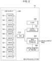
- FIG. 2 illustrates an example configuration of an image processing system 10 that generates a virtual-viewpoint image in the present embodiment.
- the image processing system 10 includes a camera group 100 including a plurality of cameras 101 to 110, a hub 210, a UI (user interface) unit 260, a control apparatus 220, an image generation apparatus 230, and a virtual-viewpoint setting unit 240.
- a camera group 100 including a plurality of cameras 101 to 110, a hub 210, a UI (user interface) unit 260, a control apparatus 220, an image generation apparatus 230, and a virtual-viewpoint setting unit 240.
- FIG. 1 An example arrangement of the cameras included in the camera group 100 is illustrated in FIG. 1 .
- the plurality of cameras are arranged so as to surround a sports field that is a target of image capturing, and all the cameras are pointed at the same point of interest 130 and perform image capturing from respective different directions to obtain a plurality of captured images, which are used to generate a virtual-viewpoint image.
- a point of interest in the present embodiment is a point at which the optical axes of the plurality of cameras intersect, that is, a point that corresponds to the center of the captured images captured by the plurality of cameras.
- the optical axes of all the cameras need not intersect at the point of interest, and the point of interest needs to be included in at least the captured images captured by the plurality of cameras.
- Each camera included in the camera group 100 is, for example, a digital camera and may be a camera capturing still images, a camera capturing moving images, or a camera capturing both still images and moving images.
- a description is given on the assumption that the term "image” is a term that includes a still image and a moving image unless otherwise noted.
- a combination of an image capturing unit including an image sensor and a lens for concentrating light rays on the image sensor is called a camera.
- the image processing system 10 uses images captured by the camera group 100 to generate a virtual-viewpoint image of a scene occurring near the point of interest 130.
- the present embodiment is not limited to this, and a plurality of points of interest may be present. That is, some of the cameras included in the camera group 100 may point at a first point of interest and perform image capturing, and the remaining cameras may point at a second point of interest different from the first point of interest and perform image capturing.
- the number of cameras included in the camera group 100 is not limited to ten, and more than one camera needs to be included. Further, the camera group 100 need not surround the point of interest 130 from all directions.
- the installation place of the camera group 100 is not limited to a sports field and may be, for example, a theater or a live-performance stage.
- Images captured by the camera group 100 are sent to the control apparatus 220 and the image generation apparatus 230 via the hub 210.
- the control apparatus 220 accepts an instruction via the UI unit 260 and controls each camera included in the camera group 100.
- the UI unit 260 includes a display unit that displays a GUI (graphical user interface) for operations and an operation unit, such as a mouse, a keyboard, an operation button, or a touch panel, and accepts operations by a user.
- the control apparatus 220 obtains from the UI unit 260 information corresponding to a user operation and transmits to each camera on the basis of the information, for example, a change instruction for changing an image capture parameter related to image capturing or a change instruction for changing the image capture position and image capture direction.
- the image capture parameter in the present embodiment includes, for example, at least one of the zoom value, the focus value, and the aperture value of the camera.
- the content of the image capture parameter is not limited to these.
- Each camera changes the image capture parameter in accordance with an instruction received from the control apparatus 220.
- the pan head is controlled in accordance with an instruction from the control apparatus to change the image capture position and image capture direction of the camera.
- the image generation apparatus 230 generates a virtual-viewpoint image in accordance with the position and direction of a virtual viewpoint set by the virtual-viewpoint setting unit 240. Specifically, the virtual-viewpoint setting unit 240 sets a virtual viewpoint specified on the basis of a user operation or a virtual viewpoint automatically specified. The image generation apparatus 230 performs on the basis of a plurality of captured images obtained from the camera group 100, a foreground-background separation process for separating a predetermined object area and the other area in each image to generate a 3D model from a separated foreground image.
- the image generation apparatus 230 obtains viewpoint information indicating the position and orientation of the specified virtual viewpoint from the virtual-viewpoint setting unit 240 and performs a rendering process using the 3D model in accordance with the specified virtual viewpoint to generate a virtual-viewpoint image that represents a view at the virtual viewpoint.
- a virtual-viewpoint image in the present embodiment includes a desired-viewpoint image (free-viewpoint image) corresponding to a viewpoint specified by the user as desired. Further, an image corresponding to a viewpoint specified by the user from among a plurality of candidates and an image corresponding to a viewpoint automatically specified by the apparatus are also included in the virtual-viewpoint image.
- a known method such as Visual Hull
- the algorithm for generating a virtual-viewpoint image is not limited to this, and a method, such as a billboard-based method, in which a 3D model is not created may be used.
- the generated virtual-viewpoint image is transmitted to, for example, a viewing terminal (not illustrated) held by a viewer, and the virtual-viewpoint image is displayed on the terminal.
- the configuration of the image processing system 10 is not limited to that illustrated in FIG. 2 .
- the plurality of cameras included in the camera group 100 may be directly connected to the control apparatus 220 or the image generation apparatus 230, or the cameras may be daisy-chained.
- the image generation apparatus 230 may be formed as a single apparatus or may be formed of a plurality of apparatuses connected to one another.
- the control apparatus 220 may include the UI unit 260, or the control apparatus 220 and the image generation apparatus 230 are formed as one apparatus.
- the apparatuses included in the image processing system 10 may be connected to one another by wire or wirelessly.
- FIG. 19 illustrates an example hardware configuration of the control apparatus 220.
- the control apparatus 220 includes a CPU 2201, a ROM 2202, a RAM 2203, an auxiliary storage device 2204, a communication I/F 2205, and a bus 2206.
- the CPU 2201 uses a computer program and data stored in the ROM 2202 or the RAM 2203 to control the control apparatus 220 as a whole.
- the control apparatus 220 may include one or more dedicated hardware components different from the CPU 2201, and the dedicated hardware components may perform at least part of the processing by the CPU 2201. Examples of the dedicated hardware components include an ASIC (application-specific integrated circuit), an FPGA (field-programmable gate array), and a DSP (digital signal processor).
- ASIC application-specific integrated circuit
- FPGA field-programmable gate array
- DSP digital signal processor
- the ROM 2202 stores programs and parameters that need not be changed.
- the RAM 2203 temporarily stores, for example, programs and data supplied from the auxiliary storage device 2204 and data externally supplied via the communication I/F 2205.
- the auxiliary storage device 2204 is formed of, for example, a hard disk drive and stores various types of content data including images and sounds.
- the communication I/F 2205 is used to communicate with external apparatuses, such as the camera group 100 and the image generation apparatus 230.
- external apparatuses such as the camera group 100 and the image generation apparatus 230.
- a communication cable is connected to the communication I/F 2205.
- the communication I/F 2205 includes an antenna.
- the bus 2206 connects the units of the control apparatus 220 to convey information. Note that in a case where the control apparatus 220 includes the UI unit 260, the control apparatus 220 includes the display unit and the operation unit in addition to the configuration illustrated in FIG. 19 .
- the hardware configuration of the image generation apparatus 230 is similar to the configuration of the control apparatus 220.
- An image obtaining unit 221 obtains and transmits to the UI unit 260 an image based on image capturing by each camera.
- a user performs an operation while watching an image displayed by the UI unit 260 to give an instruction for adjusting the position and orientation of each camera or specify an adjustment of the focus of the camera.
- a command transmission unit 222 transmits commands to each camera and transmits a command for starting or ending image capturing and a command for, for example, controlling an in-focus position (in-focus point) on which the camera is focused or controlling the zoom value or the aperture value of the camera.
- a focus setting unit 225 sets the in-focus point of each camera to a desired place and can set the in-focus point in an area away from the center of the captured image.
- a parameter obtaining unit 223 obtains from each camera, a parameter, such as the current zoom value, focus value, or aperture value, related to image capturing and may obtain as the focus value not only the focus encoder value of the lens but also the contrast value of a focus area.
- An in-focus range calculation unit 226 calculates a range in focus (in-focus range) in the front and the rear of the in-focus point on the basis of the parameter obtained by the parameter obtaining unit 223.
- An in-focus point movement amount calculation unit 227 performs, in a case of changing the in-focus point of a camera, a calculation for converting the amount of movement of the in-focus point to the amount of movement of the focal length of the lens.
- a parameter setting unit 224 sets the amount of movement of the focal length as the focus encoder value and changes the focus value of the camera by command transmission by the command transmission unit 222. Note that the parameter setting unit 224 may set not only the focus value but also the zoom value and the aperture value.
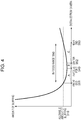
- FIG. 4 is a diagram illustrating a relationship between the distance from a camera and the amount of blurring in a case where the aperture value and the in-focus point are fixed.
- the position of the subject is an in-focus point 340.
- the amount of blurring steeply increases as the distance from the camera changes in the direction from the in-focus point 340 toward the camera side (the leftward direction in FIG. 4 ), and the amount of blurring gently increases in the direction away from the camera (the rightward direction in FIG. 4 ).
- an area that is in focus (an area in which the amount of blurring is smaller than or equal to the allowable amount of blurring 310) is an in-focus range 350.
- the size of the in-focus range corresponds to, for example, the depth of field of the camera.
- the distance from the front end 351 of the in-focus range 350 to the in-focus point 340 is A
- the distance from the rear end 353 to the in-focus point 340 is B + C
- the center 352 of the in-focus range 350 is at a position further from the camera than the in-focus point 340. Note that the length of A + B is equal to C.
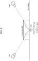
- FIG. 5 illustrates a case where cameras are pointed at a marker 420 placed on the ground as a point of interest 430 and are focused on the marker 420 to set an in-focus point 440. That is, the marker 420, the point of interest 430, and the in-focus point 440 are at the same position.
- a description is given below while focusing on the camera 101 and the camera 108 arranged opposite to each other in the camera group 100; however, the same applies to the other cameras pointed at the same point of interest. In the situation illustrated in FIG.
- the in-focus range of each camera is larger in a part on the far side of the in-focus point than in a part on the near side of the in-focus point, and therefore, an in-focus area 450 that is the common part of the in-focus range of the camera 101 and the in-focus range of the camera 108 is an area up to a position away from the point of interest 430 toward each camera by a distance A.
- the in-focus area 450 might not have an exact rectangular shape but is represented here by a rectangle for simplification of description. Note that in a case where the distances from the point of interest 430 to the respective cameras are different, the distance A has different values for the respective cameras.
- FIG. 6 illustrates a case where the in-focus point of each camera is moved closer to the camera side than the point of interest 430 in order to enlarge the in-focus area.
- the camera 101 is focused on an in-focus point 541, and the camera 108 is focused on an in-focus point 542.
- an in-focus area 550 is an area up to a position away from the point of interest 430 toward each camera by a distance A + B and is larger than the area in the case where the in-focus point matches the point of interest 430 illustrated in FIG. 5 . Note that in the case where the distances from the point of interest 430 to the respective cameras are different, the distance B from the point of interest 430 to each in-focus point has different values for the respective cameras.
- a method for moving an in-focus point is described with reference to FIG. 7 .
- FIG. 7 illustrates a single lens, namely, the lens 610, for simplification; however, in actuality, a plurality of lenses are combined and the positions thereof are controlled to change the focal length and the zoom value.
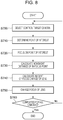
- the processing illustrated in FIG. 8 is started at the timing when the camera group 100 is installed and an instruction for making an adjustment of the camera group 100 before generation of a virtual-viewpoint image is input to the control apparatus 220.
- the instruction for making the adjustment may be given by a user operation via the UI unit 260, or the instruction may be input from another apparatus.
- the timing of starting the processing illustrated in FIG. 8 is not limited to this.
- the processing illustrated in FIG. 8 is implemented by the CPU 2201 loading to the RAM 2203 and executing a program stored in the ROM 2202. Note that at least part of the processing illustrated in FIG. 8 may be implemented as one or more dedicated hardware components different from the CPU 2201. The same applies to processing illustrated in the flowcharts in FIG. 13 , FIG. 16 , and FIG. 18 described below.
- the control apparatus 220 selects a target camera that is to be a control target from the camera group 100 and obtains the image capture parameter from the target camera.
- the command transmission unit 222 gives an instruction for determining a point of interest and pointing the target camera at the point of interest.
- a predetermined object such as a 2D marker
- the UI unit 260 accepts a user operation for specifying the position of the marker located within the image capture range of a camera, and the parameter obtaining unit 223 obtains coordinate information corresponding to the specification.
- the parameter setting unit 224 sets a parameter for adjusting at least either the position or orientation of the target camera on the basis of the obtained coordinate information such that the position of the point of interest matches the position of the marker.
- the command transmission unit 222 transmits an instruction corresponding to the set parameter to the target camera.
- time taken to point the plurality of cameras included in the camera group 100 at the same point of interest can be saved.
- the point of interest may be determined in accordance with a position specified by the user as desired regardless of the marker position.
- the control apparatus 220 may detect the marker position or a predetermined feature point in a captured image obtained by the image obtaining unit 221 by making an image analysis and automatically determine a point of interest.
- the point of interest of the target camera may be determined so as to match the direction in which a camera other than the target camera is pointed.
- the command transmission unit 222 gives an instruction for focusing the target camera on the point of interest on the basis of setting by the focus setting unit 225.
- the in-focus point movement amount calculation unit 227 calculates the amount of movement of the in-focus point from the point of interest on the basis of the image capture parameter of the target camera such that the distance from the target camera to the in-focus point is shorter than the distance from the target camera to the point of interest.
- the in-focus range calculation unit 226 calculates the in-focus range in the front and the rear of the in-focus point on the basis of the image capture parameter of the target camera obtained by the parameter obtaining unit 223, and the in-focus point movement amount calculation unit 227 calculates the amount of movement of the in-focus point from the point of interest such that the point of interest is at the center of the in-focus range.
- the in-focus point movement amount calculation unit 227 calculates the amount of focus change of the lens from the amount of movement of the in-focus point.
- the command transmission unit 222 transmits to the target camera an adjustment parameter corresponding to the calculated amount of focus change to thereby give an instruction for changing the in-focus point of the target camera.
- control is performed such that the center of the in-focus range of the target camera corresponds to the point of interest.
- the size of the common part of the in-focus ranges of a plurality of cameras (the in-focus area 550 in FIG. 6 ) can be maximized.
- the control is not limited to this, and control may be performed such that the in-focus point is at a position closer to the target camera than the point of interest.
- control is performed such that the point of interest is included in the in-focus range of the target camera, a virtual-viewpoint image including the vicinity of the point of interest can be generated with high image quality.
- the control apparatus 220 checks whether the processing from S710 to S750 is completed for all cameras included in the camera group 100. If the processing is not completed for all cameras, the flow returns to S700, and the control apparatus 220 selects a camera for which the processing is not yet performed as a control target camera. On the other hand, if the processing is completed for all cameras, the processing in FIG. 8 ends. Note that the case where the control apparatus 220 controls all cameras is described here; however, the control is not limited to this. The control apparatus 220 may perform the processing from S710 to S750 for some of the cameras included in the camera group 100.
- the in-focus point of the target camera is controlled such that the in-focus point of the target camera matches the position of the marker, and subsequently, the in-focus point of the target camera is controlled such that the in-focus point comes closer to the target camera.
- the in-focus point is adjusted with reference to the position of the marker included in common in the image capture ranges of the plurality of cameras, and therefore, the in-focus points of the plurality of cameras can be automatically adjusted with precision.
- the procedure for controlling the in-focus points is not limited to this.
- control apparatus 220 may obtain position information of the marker and position information of the target camera and directly set on the basis of these pieces of position information, the in-focus point at a position closer to the target camera than the marker without focusing on the marker.
- the control apparatus 220 may move the position of the target camera in the direction opposite to the image capture direction instead of bringing the in-focus point of the target camera closer to the target camera to thereby perform control such that the in-focus point comes closer to the target camera than the point of interest.
- the control apparatus 220 controls the in-focus positions of the plurality of cameras that perform image capturing from respective different directions in order to generate a virtual-viewpoint image corresponding to a specified viewpoint. Specifically, the control apparatus 220 obtains an image capture parameter related to image capturing by one or more cameras included in the camera group 100. The control apparatus 220 controls the in-focus position of a target camera corresponding to the obtained image capture parameter on the basis of the image capture parameter such that the distance from the target camera to the in-focus position of the target camera is shorter than the distance from the target camera to the point of interest.
- the in-focus area that is the common part of the in-focus ranges of the respective cameras included in the camera group 100 can be enlarged, and a virtual-viewpoint image of an image capture area in the vicinity of the point of interest can be generated with high image quality by using captured images obtained by the camera group 100.
- FIG. 5 a method for enlarging an in-focus area by setting a point of interest in the air is described.
- the marker 420 placed on the ground is set as the point of interest 430 and the position of the point of interest 430 is set as the in-focus point 440
- a part of the in-focus area on the side further from the camera than the in-focus point is present below ground, and therefore, it is not possible to effectively use the entire in-focus area.
- FIG. 9 An example where an in-focus area that can be effectively used (is present above the ground) is enlarged by setting a point of interest in the air is illustrated in FIG. 9 . In the example illustrated in FIG.
- the positions and orientations of the plurality of cameras are adjusted such that the position of a point of interest 830 is a position away from the position of the marker 420 in the vertical direction.
- the in-focus point is located at the center of the in-focus area present above the ground, and the in-focus area that can be effectively used has a size twice as large as that in the case illustrated in FIG. 5 .
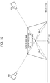
- FIG. 10 illustrates a case where a point of interest is set at a position higher than that in the case illustrated in FIG. 9 by taking into consideration the in-focus point being located on the nearer side than the center of the in-focus range of each camera as described with reference to FIG. 4 .
- the entire in-focus area is present above the ground, and the in-focus area that can be effectively used is larger than that in the case illustrated in FIG. 9 .
- the point of interest may be set at a position shifted from immediately above the marker in the horizontal direction.
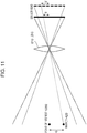
- FIG. 11 illustrates a position at which an image of the marker 420 is formed on the sensor 620 when a point of interest is set above the marker 420.
- the marker 420 and a point of interest 1030 are projected onto the sensor 620, and the height G of the point of interest 1030 corresponds to the length g on the sensor 620.
- the position on the sensor 620 changes in accordance with the zoom value of the lens 610, and the distance g on the sensor 620 for a certain zoom value changes to g' when the zoom value is increased. That is, when the height of the position, from the marker, at which a point of interest is to be set is determined, the position of the marker 420 on the sensor 620 is determined on the basis of the image capture parameter, such as the zoom value.
- FIG. 12 illustrates a screen on which a captured image obtained by a camera is displayed.
- the position and orientation of the camera are adjusted such that an image of the marker 420 is present at a position away from the center of the sensor 620 by g, so that the point of interest can be set at a position at a desired height.
- the in-focus point is set at a position corresponding to the distance from the camera to the marker 420.
- the camera is capturing an image obliquely from above the marker 420, and therefore, when the camera is focused on the marker position, the in-focus point is actually at a position slightly further from the camera than the point of interest.
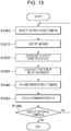
- the control apparatus 220 selects a target camera that is to be a control target from the camera group 100 and obtains the image capture parameter of the target camera.
- the control apparatus 220 uses a captured image obtained from the target camera and information corresponding to a user operation obtained from the UI unit 260 to identify a maker that is a reference for setting a point of interest and that is placed on the ground.
- the in-focus range calculation unit 226 calculates on the basis of the image capture parameter of the target camera, the size of the in-focus area that is hidden below ground in a case where the target camera is focused on the marker.
- the parameter setting unit 224 sets the height of the point of interest to be set.
- the height of the point of interest may be set such that the point of interest is at the center of the in-focus area above the ground as illustrated in FIG. 9 , may be set such that the size of the in-focus area above the ground is maximized as illustrated in FIG. 10 , or may be set to another height.
- the parameter setting unit 224 calculates the marker position on the sensor corresponding to the set height of the point of interest.
- the command transmission unit 222 gives an instruction for adjusting at least either the position or orientation of the target camera such that the maker position on the sensor comes to a desired position, that is, the position of the point of interest is at the height set in accordance with the image capture parameter.
- the command transmission unit 222 outputs to the target camera an adjustment parameter for changing at least either the position or orientation of the target camera to give an instruction for the adjustment.
- the command transmission unit 222 gives an instruction for changing the focus value of the target camera such that the target camera is focused on the marker position.
- control apparatus 220 may focus the target camera on a position, such as the point of interest, other than the marker position.
- a position such as the point of interest
- the control apparatus 220 may focus the target camera on a position, such as the point of interest, other than the marker position.
- a virtual-viewpoint image corresponding to an image capture area in the vicinity of the marker can be generated with high image quality.
- the control apparatus 220 checks whether the processing from S1210 to S1250 is completed for all cameras included in the camera group 100. If the processing is not completed for all cameras, the flow returns to S1200, and the control apparatus 220 selects a camera for which the processing is not yet performed as a control target camera. On the other hand, if the processing is completed for all cameras, the processing in FIG. 13 ends. Note that the case where the control apparatus 220 controls all cameras is described here; however, the control is not limited to this. The control apparatus 220 may perform the processing from S1210 to S1250 for some of the cameras included in the camera group 100.
- the control apparatus 220 sets the position of the point of interest with reference to the position of the maker placed on the ground. Accordingly, the point of interest can be automatically set with precision at an appropriate height corresponding to the in-focus range of the camera.
- the method for setting the position of the point of interest is not limited to this.
- the marker may be at a position above the ground, or a predetermined feature point extracted from a captured image may be used instead of the marker.
- the control apparatus 220 may obtain information for identifying the height of the installation position of each camera and control the position of the point of interest on the basis of the obtained information.
- the control apparatus 220 outputs to the target camera an instruction for changing the position or orientation of the target camera.
- the position of the point of interest can be automatically adjusted, and the administrator of the camera group 100 can save time.
- the specifics of the control for adjusting the position or orientation of the target camera by the control apparatus 220 are not limited to this.
- the control apparatus 220 may display on a display unit or output from an audio output unit, information about a change in at least either the position or orientation of a camera (information indicating that, for example, the orientation of which camera is to be adjusted to what degree).
- the display unit and the audio output unit may be included in the control apparatus or may be included in a terminal owned by the administrator who installs and adjusts the cameras. With such a method, even in a case where an automatic adjustment of the position or orientation of a camera is not possible, the administrator can appropriately adjust the position or orientation of the camera on the basis of the displayed information or output sound.
- the control apparatus 220 controls the plurality of cameras that perform image capturing from respective different directions in order to generate a virtual-viewpoint image corresponding to a specified viewpoint. Specifically, the control apparatus 220 obtains an image capture parameter related to image capturing by one or more cameras included in the camera group 100. The control apparatus 220 performs control for adjusting at least either the position or orientation of the target camera corresponding to the obtained image capture parameter such that the position of the point of interest at which the plurality of cameras are pointed is at a height corresponding to the image capture parameter.
- the in-focus area that is the common part of the in-focus ranges of the respective cameras included in the camera group 100 can be enlarged, and a virtual-viewpoint image of an image capture area in the vicinity of the point of interest can be generated with high image quality by using captured images obtained by the camera group 100.
- the in-focus area that is present above the ground and that can be effectively used can be made larger than that in the case of setting the point of interest on the ground.
- FIG. 14 illustrates a case where a point of interest 1330 is set in the air relative to the marker 420 as in FIG. 9 and in-focus points are set at positions closer to the camera than the point of interest 1330 as in FIG. 6 .
- the camera 101 is focused on an in-focus point 1341
- the camera 108 is focused on an in-focus point 1342
- the lengths of A, B, and C are different depending on the camera.
- the timing of starting the processing illustrated in FIG. 16 is similar to that for the processing illustrated in FIG. 8 .
- the processing from S1400 to S1450 is similar to that from S1210 to S1250 in FIG. 13 , and the control apparatus 220 controls the position and orientation of the camera such that the point of interest is located above the marker, and focuses the camera on the marker position.
- the processing from S1460 to S1480 is similar to that from S730 to S750 in FIG. 8 , and the control apparatus 220 controls the in-focus point of the target camera such that the in-focus point comes closer to the target camera than the point of interest.
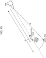
- the camera 108 is capturing an image of the marker 420 obliquely from above the marker 420. Therefore, the distance M from the camera 108 to the marker 420 is longer than the distance V from the camera 108 to the point of interest 1330.
- the in-focus point is at a position further from the camera 108 than the point of interest 1330.
- the distance from the point of interest 1330 to the in-focus point 1342 after movement is B, and therefore, the amount of movement of the in-focus point in an adjustment made after focusing on the marker 420 is represented by M - V + B.
- the control apparatus 220 checks whether the processing is completed for all cameras. If the processing is not completed for all cameras, the processing is repeated for the number of all cameras. Accordingly, the point of interest is set in the air, the in-focus area hidden below ground can be effectively used, and further, the in-focus range can be used without being wasted.
- the control apparatus 220 checks whether the processing from S1410 to S1480 is completed for all cameras included in the camera group 100. If the processing is not completed for all cameras, the flow returns to S1400, and the control apparatus 220 selects a camera for which the processing is not yet performed as a control target camera. On the other hand, if the processing is completed for all cameras, the processing in FIG. 16 ends. Note that the case where the control apparatus 220 controls all cameras is described here; however, the control is not limited to this. The control apparatus 220 may perform the processing from S1410 to S1490 for some of the cameras included in the camera group 100.
- the in-focus area can be further made larger than that in the case described with reference to FIG. 6 or FIG. 9 .
- the control apparatus 220 may change the image capture parameter, such as the aperture value, of each camera.
- the image capture parameter such as the aperture value
- the control apparatus 220 may use this feature to set the aperture value such that the in-focus area has a desired size.
- FIG. 18 illustrates an operation flow of the control apparatus 220 in a case of inserting a process for setting the aperture value in the processing flow described with reference to FIG. 16 .
- the control apparatus 220 sets the point of interest of the target camera selected in S1400 by the processing from S1400 to S1440, and subsequently sets the aperture value of the target camera in S1645.
- the parameter obtaining unit 223 obtains the zoom value of the target camera and information indicating a predetermined area in the image capture range that is a target for which a virtual-viewpoint image is generated.
- the parameter setting unit 224 sets the aperture value on the basis of the obtained information indicating the predetermined area and the obtained zoom value such that the size of the in-focus range becomes larger than the size of the predetermined area, and the command transmission unit 222 gives the target camera an instruction for changing the aperture value. Subsequently, the processing from S1450 to S1490 is performed as in the case illustrated in FIG. 16 . Note that the process for setting the aperture value need not be between S1440 and S1450 and may be, for example, between S1480 and S1490. Further, the process for setting the aperture value may be inserted in the processing flow described with reference to FIG. 8 or FIG. 13 .
- the control apparatus 220 controls the aperture value of the camera in accordance with control of the point of interest or the in-focus point
- the in-focus area can be further enlarged even in a case where the size of the in-focus area does not become sufficiently large only by changing the point of interest or changing the in-focus point.
- the amount of adjustment of the aperture value is not limited to the above.
- the aperture value may be specified by the user via the UI unit 260.
- the present embodiment a case where all cameras included in the camera group 100 are pointed at the same point of interest is mainly described; however, the present embodiment is not limited to this.
- a plurality of points of interest may be present, and cameras in a first group and cameras in a second group may be pointed at different points of interest.
- the processing illustrated in, for example, the above-described flowcharts is performed for each group of cameras that are pointed at the same point of interest.
- the present invention can be implemented by processing of supplying a program for implementing one or more functions of the above-described embodiments to a system or apparatus via a network or storage medium, and causing one or more processors in the computer of the system or apparatus to read out and execute the program.
- the present invention can also be implemented by a circuit (for example, an ASIC) for implementing one or more functions.
- the program may be recorded to a computer-readable recording medium and provided.
Landscapes
- Engineering & Computer Science (AREA)
- Multimedia (AREA)
- Signal Processing (AREA)
- Physics & Mathematics (AREA)
- General Physics & Mathematics (AREA)
- Human Computer Interaction (AREA)
- Studio Devices (AREA)
- Details Of Cameras Including Film Mechanisms (AREA)
- Closed-Circuit Television Systems (AREA)
Abstract
Description
- The present invention relates to a technique for generating a virtual-viewpoint image by using a plurality of cameras.
- In the related art, a technique in which image capturing of a subject is performed by a plurality of cameras installed at different positions from a plurality of directions in synchronization with one another and a plurality of captured images (multi-view images) obtained by the image capturing are used to generate a virtual-viewpoint image has been proposed. The virtual-viewpoint image thus generated is an image that represents a view at a virtual viewpoint that is not limited by the installation positions of the cameras.
- PTL1 discloses a technique in which a three-dimensional model is generated on the basis of images obtained by image capturing of a subject from a plurality of directions using a plurality of cameras and texture is attached to the generated three-dimensional model to generate a virtual-viewpoint image corresponding to a viewpoint specified by a user.
- PTL1: Japanese Patent Laid-Open No.
2014-215828 - In a case of generating a virtual-viewpoint image of a predetermined area by using captured images obtained by a plurality of cameras, a virtual-viewpoint image of high image quality can be generated when the predetermined area is included in the common part of the in-focus ranges (ranges in focus) of the respective cameras. However, in a case where the common part of the in-focus ranges of the respective cameras are small, an area, in the generated virtual-viewpoint image, not included in the common part is large, and the image quality of the virtual-viewpoint image may be compromised.
- The present invention has been made in view of the above-described issue, and an object thereof is to make it possible to generate a virtual-viewpoint image of high image quality by performing control such that the common part of the in-focus ranges of a plurality of cameras is enlarged.
- To address the above-described issue, a control apparatus according to the present invention has, for example, the following configuration. That is, the control apparatus is a control apparatus for controlling a plurality of cameras that perform image capturing from respective different directions in order to generate a virtual-viewpoint image corresponding to a specified viewpoint, including: obtaining means configured to obtain an image capture parameter related to image capturing by one or more cameras included in the plurality of cameras; and control means configured to control on the basis of the image capture parameter obtained by the obtaining means, an in-focus position, on an optical axis, of a target camera corresponding to the image capture parameter such that a distance from the target camera to the in-focus position of the target camera is shorter than a distance from the target camera to a position that is on the optical axis of the target camera and that is closest to optical axes of the other cameras included in the plurality of cameras.
- According to the present invention, it is possible to generate a virtual-viewpoint image of high image quality by performing control such that the common part of the in-focus ranges of a plurality of cameras is enlarged.
-
-
FIG. 1 is a diagram illustrating an example arrangement of a plurality of cameras. -
FIG. 2 is a diagram illustrating a configuration of an image processing system according to an embodiment. -
FIG. 3 is a diagram illustrating a functional configuration of a control apparatus according to the embodiment. -
FIG. 4 is a diagram illustrating a relationship between an in-focus point and the amount of blurring. -
FIG. 5 is a diagram illustrating an in-focus area when a point of interest is set at an in-focus point. -
FIG. 6 is a diagram illustrating an in-focus area when in-focus points are changed to the near side. -
FIG. 7 is a diagram illustrating a relationship between a focal length and an in-focus point. -
FIG. 8 is a flowchart for describing operations of the control apparatus when an in-focus point is changed to the near side. -
FIG. 9 is a diagram illustrating an in-focus area when a point of interest is set in the air. -
FIG. 10 is a diagram illustrating an in-focus area when a point of interest is set in the air. -
FIG. 11 is a diagram illustrating a relationship between a focal length and the angle of view. -
FIG. 12 is a diagram illustrating an example camera screen at the time of focusing. -
FIG. 13 is a flowchart for describing operations of the control apparatus when a point of interest is set in the air. -
FIG. 14 is a diagram illustrating an in-focus area when a point of interest is set in the air and in-focus points are changed to the near side. -
FIG. 15 is a diagram illustrating the amount of movement of an in-focus point when a point of interest is set in the air and the in-focus point is changed to the near side. -
FIG. 16 is a flowchart for describing operations of the control apparatus when a point of interest is set in the air and an in-focus point is changed to the near side. -
FIG. 17 is a diagram illustrating a relationship between an aperture value and the amount of blurring. -
FIG. 18 is a flowchart for describing operations of the control apparatus when an aperture value is changed. -
FIG. 19 is a diagram illustrating a hardware configuration of the control apparatus. -
FIG. 2 illustrates an example configuration of animage processing system 10 that generates a virtual-viewpoint image in the present embodiment. Theimage processing system 10 includes acamera group 100 including a plurality ofcameras 101 to 110, ahub 210, a UI (user interface)unit 260, acontrol apparatus 220, animage generation apparatus 230, and a virtual-viewpoint setting unit 240. - An example arrangement of the cameras included in the
camera group 100 is illustrated inFIG. 1 . The plurality of cameras are arranged so as to surround a sports field that is a target of image capturing, and all the cameras are pointed at the same point ofinterest 130 and perform image capturing from respective different directions to obtain a plurality of captured images, which are used to generate a virtual-viewpoint image. A point of interest in the present embodiment is a point at which the optical axes of the plurality of cameras intersect, that is, a point that corresponds to the center of the captured images captured by the plurality of cameras. However, the optical axes of all the cameras need not intersect at the point of interest, and the point of interest needs to be included in at least the captured images captured by the plurality of cameras. That is, a position that is on the optical axis of a certain camera and that is closest to the optical axes of the other cameras is the point of interest of the camera. Each camera included in thecamera group 100 is, for example, a digital camera and may be a camera capturing still images, a camera capturing moving images, or a camera capturing both still images and moving images. In the present embodiment, a description is given on the assumption that the term "image" is a term that includes a still image and a moving image unless otherwise noted. Note that in the present embodiment, a combination of an image capturing unit including an image sensor and a lens for concentrating light rays on the image sensor is called a camera. Theimage processing system 10 uses images captured by thecamera group 100 to generate a virtual-viewpoint image of a scene occurring near the point ofinterest 130. - Note that in the present embodiment, a case where one point of interest is present is mainly described for simplification; however, the present embodiment is not limited to this, and a plurality of points of interest may be present. That is, some of the cameras included in the
camera group 100 may point at a first point of interest and perform image capturing, and the remaining cameras may point at a second point of interest different from the first point of interest and perform image capturing. The number of cameras included in thecamera group 100 is not limited to ten, and more than one camera needs to be included. Further, thecamera group 100 need not surround the point ofinterest 130 from all directions. The installation place of thecamera group 100 is not limited to a sports field and may be, for example, a theater or a live-performance stage. - Images captured by the
camera group 100 are sent to thecontrol apparatus 220 and theimage generation apparatus 230 via thehub 210. Thecontrol apparatus 220 accepts an instruction via theUI unit 260 and controls each camera included in thecamera group 100. Specifically, theUI unit 260 includes a display unit that displays a GUI (graphical user interface) for operations and an operation unit, such as a mouse, a keyboard, an operation button, or a touch panel, and accepts operations by a user. Thecontrol apparatus 220 obtains from theUI unit 260 information corresponding to a user operation and transmits to each camera on the basis of the information, for example, a change instruction for changing an image capture parameter related to image capturing or a change instruction for changing the image capture position and image capture direction. The image capture parameter in the present embodiment includes, for example, at least one of the zoom value, the focus value, and the aperture value of the camera. However, the content of the image capture parameter is not limited to these. Each camera changes the image capture parameter in accordance with an instruction received from thecontrol apparatus 220. In a case where, for example, each camera has a motor-driven pan head, the pan head is controlled in accordance with an instruction from the control apparatus to change the image capture position and image capture direction of the camera. - The
image generation apparatus 230 generates a virtual-viewpoint image in accordance with the position and direction of a virtual viewpoint set by the virtual-viewpoint setting unit 240. Specifically, the virtual-viewpoint setting unit 240 sets a virtual viewpoint specified on the basis of a user operation or a virtual viewpoint automatically specified. Theimage generation apparatus 230 performs on the basis of a plurality of captured images obtained from thecamera group 100, a foreground-background separation process for separating a predetermined object area and the other area in each image to generate a 3D model from a separated foreground image. Theimage generation apparatus 230 obtains viewpoint information indicating the position and orientation of the specified virtual viewpoint from the virtual-viewpoint setting unit 240 and performs a rendering process using the 3D model in accordance with the specified virtual viewpoint to generate a virtual-viewpoint image that represents a view at the virtual viewpoint. A virtual-viewpoint image in the present embodiment includes a desired-viewpoint image (free-viewpoint image) corresponding to a viewpoint specified by the user as desired. Further, an image corresponding to a viewpoint specified by the user from among a plurality of candidates and an image corresponding to a viewpoint automatically specified by the apparatus are also included in the virtual-viewpoint image. - In the process for generating a virtual-viewpoint image from captured images as described above, a known method, such as Visual Hull, can be used. Note that the algorithm for generating a virtual-viewpoint image is not limited to this, and a method, such as a billboard-based method, in which a 3D model is not created may be used. The generated virtual-viewpoint image is transmitted to, for example, a viewing terminal (not illustrated) held by a viewer, and the virtual-viewpoint image is displayed on the terminal.
- Note that the configuration of the
image processing system 10 is not limited to that illustrated inFIG. 2 . The plurality of cameras included in thecamera group 100 may be directly connected to thecontrol apparatus 220 or theimage generation apparatus 230, or the cameras may be daisy-chained. Theimage generation apparatus 230 may be formed as a single apparatus or may be formed of a plurality of apparatuses connected to one another. Thecontrol apparatus 220 may include theUI unit 260, or thecontrol apparatus 220 and theimage generation apparatus 230 are formed as one apparatus. The apparatuses included in theimage processing system 10 may be connected to one another by wire or wirelessly. -
FIG. 19 illustrates an example hardware configuration of thecontrol apparatus 220. Thecontrol apparatus 220 includes aCPU 2201, aROM 2202, aRAM 2203, anauxiliary storage device 2204, a communication I/F 2205, and abus 2206. TheCPU 2201 uses a computer program and data stored in theROM 2202 or theRAM 2203 to control thecontrol apparatus 220 as a whole. Note that thecontrol apparatus 220 may include one or more dedicated hardware components different from theCPU 2201, and the dedicated hardware components may perform at least part of the processing by theCPU 2201. Examples of the dedicated hardware components include an ASIC (application-specific integrated circuit), an FPGA (field-programmable gate array), and a DSP (digital signal processor). TheROM 2202 stores programs and parameters that need not be changed. TheRAM 2203 temporarily stores, for example, programs and data supplied from theauxiliary storage device 2204 and data externally supplied via the communication I/F 2205. Theauxiliary storage device 2204 is formed of, for example, a hard disk drive and stores various types of content data including images and sounds. - The communication I/
F 2205 is used to communicate with external apparatuses, such as thecamera group 100 and theimage generation apparatus 230. For example, in a case where thecontrol apparatus 220 is connected to an external apparatus by wire, a communication cable is connected to the communication I/F 2205. In a case where thecontrol apparatus 220 has a function of wirelessly communicating with external apparatuses, the communication I/F 2205 includes an antenna. Thebus 2206 connects the units of thecontrol apparatus 220 to convey information. Note that in a case where thecontrol apparatus 220 includes theUI unit 260, thecontrol apparatus 220 includes the display unit and the operation unit in addition to the configuration illustrated inFIG. 19 . The hardware configuration of theimage generation apparatus 230 is similar to the configuration of thecontrol apparatus 220. - The functional configuration of the
control apparatus 220 is described with reference toFIG. 3 . Animage obtaining unit 221 obtains and transmits to theUI unit 260 an image based on image capturing by each camera. A user performs an operation while watching an image displayed by theUI unit 260 to give an instruction for adjusting the position and orientation of each camera or specify an adjustment of the focus of the camera. Acommand transmission unit 222 transmits commands to each camera and transmits a command for starting or ending image capturing and a command for, for example, controlling an in-focus position (in-focus point) on which the camera is focused or controlling the zoom value or the aperture value of the camera. Afocus setting unit 225 sets the in-focus point of each camera to a desired place and can set the in-focus point in an area away from the center of the captured image. - A
parameter obtaining unit 223 obtains from each camera, a parameter, such as the current zoom value, focus value, or aperture value, related to image capturing and may obtain as the focus value not only the focus encoder value of the lens but also the contrast value of a focus area. An in-focusrange calculation unit 226 calculates a range in focus (in-focus range) in the front and the rear of the in-focus point on the basis of the parameter obtained by theparameter obtaining unit 223. An in-focus point movementamount calculation unit 227 performs, in a case of changing the in-focus point of a camera, a calculation for converting the amount of movement of the in-focus point to the amount of movement of the focal length of the lens. Aparameter setting unit 224 sets the amount of movement of the focal length as the focus encoder value and changes the focus value of the camera by command transmission by thecommand transmission unit 222. Note that theparameter setting unit 224 may set not only the focus value but also the zoom value and the aperture value. - Before giving a description of a procedure for controlling an in-focus point in the present embodiment, the in-focus point and the amount of blurring are described.
FIG. 4 is a diagram illustrating a relationship between the distance from a camera and the amount of blurring in a case where the aperture value and the in-focus point are fixed. For example, in a case where a camera is focused on a specific subject, the position of the subject is an in-focus point 340. At this time, the amount of blurring steeply increases as the distance from the camera changes in the direction from the in-focus point 340 toward the camera side (the leftward direction inFIG. 4 ), and the amount of blurring gently increases in the direction away from the camera (the rightward direction inFIG. 4 ). When an amount of blurring that does not significantly affect the image quality of a virtual-viewpoint image generated from captured images is defined as an allowable amount of blurring 310, an area that is in focus (an area in which the amount of blurring is smaller than or equal to the allowable amount of blurring 310) is an in-focus range 350. The size of the in-focus range corresponds to, for example, the depth of field of the camera. The distance from thefront end 351 of the in-focus range 350 to the in-focus point 340 is A, the distance from therear end 353 to the in-focus point 340 is B + C, and thecenter 352 of the in-focus range 350 is at a position further from the camera than the in-focus point 340. Note that the length of A + B is equal to C. -
FIG. 5 illustrates a case where cameras are pointed at amarker 420 placed on the ground as a point ofinterest 430 and are focused on themarker 420 to set an in-focus point 440. That is, themarker 420, the point ofinterest 430, and the in-focus point 440 are at the same position. For simplification, a description is given below while focusing on thecamera 101 and thecamera 108 arranged opposite to each other in thecamera group 100; however, the same applies to the other cameras pointed at the same point of interest. In the situation illustrated inFIG. 5 , the in-focus range of each camera is larger in a part on the far side of the in-focus point than in a part on the near side of the in-focus point, and therefore, an in-focus area 450 that is the common part of the in-focus range of thecamera 101 and the in-focus range of thecamera 108 is an area up to a position away from the point ofinterest 430 toward each camera by a distance A. The in-focus area 450 might not have an exact rectangular shape but is represented here by a rectangle for simplification of description. Note that in a case where the distances from the point ofinterest 430 to the respective cameras are different, the distance A has different values for the respective cameras. -
FIG. 6 illustrates a case where the in-focus point of each camera is moved closer to the camera side than the point ofinterest 430 in order to enlarge the in-focus area. Thecamera 101 is focused on an in-focus point 541, and thecamera 108 is focused on an in-focus point 542. At this time, an in-focus area 550 is an area up to a position away from the point ofinterest 430 toward each camera by a distance A + B and is larger than the area in the case where the in-focus point matches the point ofinterest 430 illustrated inFIG. 5 . Note that in the case where the distances from the point ofinterest 430 to the respective cameras are different, the distance B from the point ofinterest 430 to each in-focus point has different values for the respective cameras. - A method for moving an in-focus point is described with reference to
FIG. 7 . For the distance a from alens 610 of a camera to an in-focus point 640 and the distance b from thelens 610 to asensor 620, a relational expression of 1/a + 1/b = 1/f holds where f is the distance (focal length) from thelens 610 to a position at which an image is formed when parallel rays are incident on thelens 610. At this time, when the position of thesensor 620 on which an image is formed is moved by d relative to the lens, the in-focus point 640 moves by D. That is, when the amount of movement D of the in-focus point 640 to be moved is determined, the amount of movement d of thesensor 620 can be calculated. Note that in actuality, thelens 610 is moved relative to thesensor 620 instead of moving thesensor 620 relative to thelens 610.FIG. 7 illustrates a single lens, namely, thelens 610, for simplification; however, in actuality, a plurality of lenses are combined and the positions thereof are controlled to change the focal length and the zoom value. - Now, operations of the
control apparatus 220 in a case of moving an in-focus point from a point of interest to the near side to enlarge an in-focus area are described with reference to the flowchart inFIG. 8 . The processing illustrated inFIG. 8 is started at the timing when thecamera group 100 is installed and an instruction for making an adjustment of thecamera group 100 before generation of a virtual-viewpoint image is input to thecontrol apparatus 220. The instruction for making the adjustment may be given by a user operation via theUI unit 260, or the instruction may be input from another apparatus. Note that the timing of starting the processing illustrated inFIG. 8 is not limited to this. The processing illustrated inFIG. 8 is implemented by theCPU 2201 loading to theRAM 2203 and executing a program stored in theROM 2202. Note that at least part of the processing illustrated inFIG. 8 may be implemented as one or more dedicated hardware components different from theCPU 2201. The same applies to processing illustrated in the flowcharts inFIG. 13 ,FIG. 16 , andFIG. 18 described below. - In S700, the
control apparatus 220 selects a target camera that is to be a control target from thecamera group 100 and obtains the image capture parameter from the target camera. In S710, thecommand transmission unit 222 gives an instruction for determining a point of interest and pointing the target camera at the point of interest. For example, a predetermined object, such as a 2D marker, for setting a point of interest is placed in a sports field that is a target of image capturing. TheUI unit 260 accepts a user operation for specifying the position of the marker located within the image capture range of a camera, and theparameter obtaining unit 223 obtains coordinate information corresponding to the specification. Theparameter setting unit 224 sets a parameter for adjusting at least either the position or orientation of the target camera on the basis of the obtained coordinate information such that the position of the point of interest matches the position of the marker. Thecommand transmission unit 222 transmits an instruction corresponding to the set parameter to the target camera. When the point of interest is thus set by using the marker, time taken to point the plurality of cameras included in thecamera group 100 at the same point of interest can be saved. Note that the point of interest may be determined in accordance with a position specified by the user as desired regardless of the marker position. Thecontrol apparatus 220 may detect the marker position or a predetermined feature point in a captured image obtained by theimage obtaining unit 221 by making an image analysis and automatically determine a point of interest. The point of interest of the target camera may be determined so as to match the direction in which a camera other than the target camera is pointed. - In S720, the
command transmission unit 222 gives an instruction for focusing the target camera on the point of interest on the basis of setting by thefocus setting unit 225. In S730, the in-focus point movementamount calculation unit 227 calculates the amount of movement of the in-focus point from the point of interest on the basis of the image capture parameter of the target camera such that the distance from the target camera to the in-focus point is shorter than the distance from the target camera to the point of interest. Specifically, the in-focusrange calculation unit 226 calculates the in-focus range in the front and the rear of the in-focus point on the basis of the image capture parameter of the target camera obtained by theparameter obtaining unit 223, and the in-focus point movementamount calculation unit 227 calculates the amount of movement of the in-focus point from the point of interest such that the point of interest is at the center of the in-focus range. In S740, the in-focus point movementamount calculation unit 227 calculates the amount of focus change of the lens from the amount of movement of the in-focus point. In S750, thecommand transmission unit 222 transmits to the target camera an adjustment parameter corresponding to the calculated amount of focus change to thereby give an instruction for changing the in-focus point of the target camera. In the control of the in-focus point, control is performed such that the center of the in-focus range of the target camera corresponds to the point of interest. When the in-focus point is thus set, the size of the common part of the in-focus ranges of a plurality of cameras (the in-focus area 550 inFIG. 6 ) can be maximized. However, the control is not limited to this, and control may be performed such that the in-focus point is at a position closer to the target camera than the point of interest. When control is performed such that the point of interest is included in the in-focus range of the target camera, a virtual-viewpoint image including the vicinity of the point of interest can be generated with high image quality. - In S760, the
control apparatus 220 checks whether the processing from S710 to S750 is completed for all cameras included in thecamera group 100. If the processing is not completed for all cameras, the flow returns to S700, and thecontrol apparatus 220 selects a camera for which the processing is not yet performed as a control target camera. On the other hand, if the processing is completed for all cameras, the processing inFIG. 8 ends. Note that the case where thecontrol apparatus 220 controls all cameras is described here; however, the control is not limited to this. Thecontrol apparatus 220 may perform the processing from S710 to S750 for some of the cameras included in thecamera group 100. - In the description given above with reference to
FIG. 8 , the in-focus point of the target camera is controlled such that the in-focus point of the target camera matches the position of the marker, and subsequently, the in-focus point of the target camera is controlled such that the in-focus point comes closer to the target camera. With such a method, the in-focus point is adjusted with reference to the position of the marker included in common in the image capture ranges of the plurality of cameras, and therefore, the in-focus points of the plurality of cameras can be automatically adjusted with precision. However, the procedure for controlling the in-focus points is not limited to this. For example, thecontrol apparatus 220 may obtain position information of the marker and position information of the target camera and directly set on the basis of these pieces of position information, the in-focus point at a position closer to the target camera than the marker without focusing on the marker. Thecontrol apparatus 220 may move the position of the target camera in the direction opposite to the image capture direction instead of bringing the in-focus point of the target camera closer to the target camera to thereby perform control such that the in-focus point comes closer to the target camera than the point of interest. - As described with reference to
FIG. 6 to FIG. 8 , thecontrol apparatus 220 according to the present embodiment controls the in-focus positions of the plurality of cameras that perform image capturing from respective different directions in order to generate a virtual-viewpoint image corresponding to a specified viewpoint. Specifically, thecontrol apparatus 220 obtains an image capture parameter related to image capturing by one or more cameras included in thecamera group 100. Thecontrol apparatus 220 controls the in-focus position of a target camera corresponding to the obtained image capture parameter on the basis of the image capture parameter such that the distance from the target camera to the in-focus position of the target camera is shorter than the distance from the target camera to the point of interest. Accordingly, the in-focus area that is the common part of the in-focus ranges of the respective cameras included in thecamera group 100 can be enlarged, and a virtual-viewpoint image of an image capture area in the vicinity of the point of interest can be generated with high image quality by using captured images obtained by thecamera group 100. - Now, a method for enlarging an in-focus area by setting a point of interest in the air is described. As illustrated in
FIG. 5 , in the case where themarker 420 placed on the ground is set as the point ofinterest 430 and the position of the point ofinterest 430 is set as the in-focus point 440, a part of the in-focus area on the side further from the camera than the in-focus point is present below ground, and therefore, it is not possible to effectively use the entire in-focus area. An example where an in-focus area that can be effectively used (is present above the ground) is enlarged by setting a point of interest in the air is illustrated inFIG. 9 . In the example illustrated inFIG. 9 , the positions and orientations of the plurality of cameras are adjusted such that the position of a point of interest 830 is a position away from the position of themarker 420 in the vertical direction. When the point of interest is thus set and the in-focus point is set at the position of the set point of interest, the in-focus point is located at the center of the in-focus area present above the ground, and the in-focus area that can be effectively used has a size twice as large as that in the case illustrated inFIG. 5 .FIG. 10 illustrates a case where a point of interest is set at a position higher than that in the case illustrated inFIG. 9 by taking into consideration the in-focus point being located on the nearer side than the center of the in-focus range of each camera as described with reference toFIG. 4 . In this case, the entire in-focus area is present above the ground, and the in-focus area that can be effectively used is larger than that in the case illustrated inFIG. 9 . Note that in a case of setting the point of interest immediately above the marker, similar control needs to be performed for each camera, and therefore, processing can be simplified. In a case where, for example, the place where the maker is arranged or the position of the point of interest is limited, the point of interest may be set at a position shifted from immediately above the marker in the horizontal direction. -
FIG. 11 illustrates a position at which an image of themarker 420 is formed on thesensor 620 when a point of interest is set above themarker 420. Themarker 420 and a point ofinterest 1030 are projected onto thesensor 620, and the height G of the point ofinterest 1030 corresponds to the length g on thesensor 620. However, the position on thesensor 620 changes in accordance with the zoom value of thelens 610, and the distance g on thesensor 620 for a certain zoom value changes to g' when the zoom value is increased. That is, when the height of the position, from the marker, at which a point of interest is to be set is determined, the position of themarker 420 on thesensor 620 is determined on the basis of the image capture parameter, such as the zoom value. -
FIG. 12 illustrates a screen on which a captured image obtained by a camera is displayed. After the distance g between the point of interest and themarker 420 on thesensor 620 has been determined, the position and orientation of the camera are adjusted such that an image of themarker 420 is present at a position away from the center of thesensor 620 by g, so that the point of interest can be set at a position at a desired height. When afocus area 1040 of the camera is set over themarker 420, the in-focus point is set at a position corresponding to the distance from the camera to themarker 420. At this time, the camera is capturing an image obliquely from above themarker 420, and therefore, when the camera is focused on the marker position, the in-focus point is actually at a position slightly further from the camera than the point of interest. - Operations of the
control apparatus 220 in a case of setting a point of interest in the air are described with reference toFIG. 13 . The timing of starting the processing illustrated inFIG. 13 is similar to that for the processing illustrated inFIG. 8 . First, in S1200, thecontrol apparatus 220 selects a target camera that is to be a control target from thecamera group 100 and obtains the image capture parameter of the target camera. In S1210, thecontrol apparatus 220 uses a captured image obtained from the target camera and information corresponding to a user operation obtained from theUI unit 260 to identify a maker that is a reference for setting a point of interest and that is placed on the ground. In S1220, the in-focusrange calculation unit 226 calculates on the basis of the image capture parameter of the target camera, the size of the in-focus area that is hidden below ground in a case where the target camera is focused on the marker. On the basis of the result of calculation, theparameter setting unit 224 sets the height of the point of interest to be set. The height of the point of interest may be set such that the point of interest is at the center of the in-focus area above the ground as illustrated inFIG. 9 , may be set such that the size of the in-focus area above the ground is maximized as illustrated inFIG. 10 , or may be set to another height. - In S1230, the
parameter setting unit 224 calculates the marker position on the sensor corresponding to the set height of the point of interest. In S1240, thecommand transmission unit 222 gives an instruction for adjusting at least either the position or orientation of the target camera such that the maker position on the sensor comes to a desired position, that is, the position of the point of interest is at the height set in accordance with the image capture parameter. Specifically, thecommand transmission unit 222 outputs to the target camera an adjustment parameter for changing at least either the position or orientation of the target camera to give an instruction for the adjustment. In S1250, thecommand transmission unit 222 gives an instruction for changing the focus value of the target camera such that the target camera is focused on the marker position. Note that thecontrol apparatus 220 may focus the target camera on a position, such as the point of interest, other than the marker position. In a case of focusing the target camera on the point of interest, when the height of the point of interest is adjusted within a range such that the position of the marker is included in the in-focus range of the target camera, a virtual-viewpoint image corresponding to an image capture area in the vicinity of the marker can be generated with high image quality. - In S1260, the
control apparatus 220 checks whether the processing from S1210 to S1250 is completed for all cameras included in thecamera group 100. If the processing is not completed for all cameras, the flow returns to S1200, and thecontrol apparatus 220 selects a camera for which the processing is not yet performed as a control target camera. On the other hand, if the processing is completed for all cameras, the processing inFIG. 13 ends. Note that the case where thecontrol apparatus 220 controls all cameras is described here; however, the control is not limited to this. Thecontrol apparatus 220 may perform the processing from S1210 to S1250 for some of the cameras included in thecamera group 100. - In the description given above with reference to
FIG. 13 , thecontrol apparatus 220 sets the position of the point of interest with reference to the position of the maker placed on the ground. Accordingly, the point of interest can be automatically set with precision at an appropriate height corresponding to the in-focus range of the camera. However, the method for setting the position of the point of interest is not limited to this. For example, the marker may be at a position above the ground, or a predetermined feature point extracted from a captured image may be used instead of the marker. Further, thecontrol apparatus 220 may obtain information for identifying the height of the installation position of each camera and control the position of the point of interest on the basis of the obtained information. - In the description given above, the
control apparatus 220 outputs to the target camera an instruction for changing the position or orientation of the target camera. With such a method, in a case where the cameras included in thecamera group 100 have a motor-driven pan head, the position of the point of interest can be automatically adjusted, and the administrator of thecamera group 100 can save time. However, the specifics of the control for adjusting the position or orientation of the target camera by thecontrol apparatus 220 are not limited to this. For example, thecontrol apparatus 220 may display on a display unit or output from an audio output unit, information about a change in at least either the position or orientation of a camera (information indicating that, for example, the orientation of which camera is to be adjusted to what degree). The display unit and the audio output unit may be included in the control apparatus or may be included in a terminal owned by the administrator who installs and adjusts the cameras. With such a method, even in a case where an automatic adjustment of the position or orientation of a camera is not possible, the administrator can appropriately adjust the position or orientation of the camera on the basis of the displayed information or output sound. - As described with reference to
FIG. 9 to FIG. 13 , thecontrol apparatus 220 according to the present embodiment controls the plurality of cameras that perform image capturing from respective different directions in order to generate a virtual-viewpoint image corresponding to a specified viewpoint. Specifically, thecontrol apparatus 220 obtains an image capture parameter related to image capturing by one or more cameras included in thecamera group 100. Thecontrol apparatus 220 performs control for adjusting at least either the position or orientation of the target camera corresponding to the obtained image capture parameter such that the position of the point of interest at which the plurality of cameras are pointed is at a height corresponding to the image capture parameter. Accordingly, the in-focus area that is the common part of the in-focus ranges of the respective cameras included in thecamera group 100 can be enlarged, and a virtual-viewpoint image of an image capture area in the vicinity of the point of interest can be generated with high image quality by using captured images obtained by thecamera group 100. When the point of interest is set in the air and the in-focus point is set at the position of the point of interest, the in-focus area that is present above the ground and that can be effectively used can be made larger than that in the case of setting the point of interest on the ground. - Now, a method for further enlarging an in-focus area by setting a point of interest in the air and further setting an in-focus point closer to the camera than the point of interest is described.
FIG. 14 illustrates a case where a point ofinterest 1330 is set in the air relative to themarker 420 as inFIG. 9 and in-focus points are set at positions closer to the camera than the point ofinterest 1330 as inFIG. 6 . Thecamera 101 is focused on an in-focus point 1341, thecamera 108 is focused on an in-focus point 1342, and the distance from the point ofinterest 1330 to the rear end of the in-focus range is equal to the length C (= A + B) inFIG. 4 . Note that in a case where the distances from the point ofinterest 1330 to the respective cameras are different, the lengths of A, B, and C are different depending on the camera. - Operations of the
control apparatus 220 in a case of setting an in-focus point as illustrated inFIG. 14 are described with reference toFIG. 16 . The timing of starting the processing illustrated inFIG. 16 is similar to that for the processing illustrated inFIG. 8 . The processing from S1400 to S1450 is similar to that from S1210 to S1250 inFIG. 13 , and thecontrol apparatus 220 controls the position and orientation of the camera such that the point of interest is located above the marker, and focuses the camera on the marker position. The processing from S1460 to S1480 is similar to that from S730 to S750 inFIG. 8 , and thecontrol apparatus 220 controls the in-focus point of the target camera such that the in-focus point comes closer to the target camera than the point of interest. - However, as illustrated in
FIG. 15 , thecamera 108 is capturing an image of themarker 420 obliquely from above themarker 420. Therefore, the distance M from thecamera 108 to themarker 420 is longer than the distance V from thecamera 108 to the point ofinterest 1330. When thecamera 108 is focused on the marker position, the in-focus point is at a position further from thecamera 108 than the point ofinterest 1330. The distance from the point ofinterest 1330 to the in-focus point 1342 after movement is B, and therefore, the amount of movement of the in-focus point in an adjustment made after focusing on themarker 420 is represented by M - V + B. In S1490, thecontrol apparatus 220 checks whether the processing is completed for all cameras. If the processing is not completed for all cameras, the processing is repeated for the number of all cameras. Accordingly, the point of interest is set in the air, the in-focus area hidden below ground can be effectively used, and further, the in-focus range can be used without being wasted. - In S1490, the
control apparatus 220 checks whether the processing from S1410 to S1480 is completed for all cameras included in thecamera group 100. If the processing is not completed for all cameras, the flow returns to S1400, and thecontrol apparatus 220 selects a camera for which the processing is not yet performed as a control target camera. On the other hand, if the processing is completed for all cameras, the processing inFIG. 16 ends. Note that the case where thecontrol apparatus 220 controls all cameras is described here; however, the control is not limited to this. Thecontrol apparatus 220 may perform the processing from S1410 to S1490 for some of the cameras included in thecamera group 100. - As described with reference to
FIG. 14 to FIG. 16 , when a point of interest is set in the air and the in-focus point is set closer to the camera than the point of interest, the in-focus area can be further made larger than that in the case described with reference toFIG. 6 orFIG. 9 . - A case where the in-focus area is enlarged by moving the in-focus point or the point of interest is mainly described above on the assumption that the aperture value of the camera is fixed; however, the
control apparatus 220 may change the image capture parameter, such as the aperture value, of each camera. As illustrated inFIG. 17 , as the aperture value of a camera is changed, the amount of blurring changes. Specifically, when the aperture value is made larger, the amount of blurring becomes smaller than that in a case where the aperture value is small. That is, in a case where the allowable amount of blurring 310 remains unchanged, an in-focus range 1550 is large when the aperture value is large. Thecontrol apparatus 220 may use this feature to set the aperture value such that the in-focus area has a desired size. -
FIG. 18 illustrates an operation flow of thecontrol apparatus 220 in a case of inserting a process for setting the aperture value in the processing flow described with reference toFIG. 16 . Thecontrol apparatus 220 sets the point of interest of the target camera selected in S1400 by the processing from S1400 to S1440, and subsequently sets the aperture value of the target camera in S1645. In S1645, for example, theparameter obtaining unit 223 obtains the zoom value of the target camera and information indicating a predetermined area in the image capture range that is a target for which a virtual-viewpoint image is generated. Theparameter setting unit 224 sets the aperture value on the basis of the obtained information indicating the predetermined area and the obtained zoom value such that the size of the in-focus range becomes larger than the size of the predetermined area, and thecommand transmission unit 222 gives the target camera an instruction for changing the aperture value. Subsequently, the processing from S1450 to S1490 is performed as in the case illustrated inFIG. 16 . Note that the process for setting the aperture value need not be between S1440 and S1450 and may be, for example, between S1480 and S1490. Further, the process for setting the aperture value may be inserted in the processing flow described with reference toFIG. 8 orFIG. 13 . - Accordingly, when the
control apparatus 220 controls the aperture value of the camera in accordance with control of the point of interest or the in-focus point, the in-focus area can be further enlarged even in a case where the size of the in-focus area does not become sufficiently large only by changing the point of interest or changing the in-focus point. Note that the amount of adjustment of the aperture value is not limited to the above. For example, the aperture value may be specified by the user via theUI unit 260. - Note that in the present embodiment, a case where all cameras included in the
camera group 100 are pointed at the same point of interest is mainly described; however, the present embodiment is not limited to this. A plurality of points of interest may be present, and cameras in a first group and cameras in a second group may be pointed at different points of interest. In this case, the processing illustrated in, for example, the above-described flowcharts is performed for each group of cameras that are pointed at the same point of interest. - The present invention can be implemented by processing of supplying a program for implementing one or more functions of the above-described embodiments to a system or apparatus via a network or storage medium, and causing one or more processors in the computer of the system or apparatus to read out and execute the program. The present invention can also be implemented by a circuit (for example, an ASIC) for implementing one or more functions. Further, the program may be recorded to a computer-readable recording medium and provided.
- The present invention is not limited to the above embodiments and various changes and modifications can be made within the spirit and scope of the present invention. Therefore, to apprise the public of the scope of the present invention, the following claims are made.
- This application claims priority from Japanese Patent Application No.
2018-045957 filed March 13, 2018
Claims (21)
- A control apparatus for controlling a plurality of cameras that perform image capturing from a plurality of directions in order to generate a virtual-viewpoint image, characterized by comprising:obtaining means configured to obtain an image capture parameter related to image capturing by one or more cameras included in the plurality of cameras; andcontrol means configured to control on the basis of the image capture parameter obtained by the obtaining means, an in-focus position, on an optical axis, of a target camera corresponding to the image capture parameter such that a distance from the target camera to the in-focus position of the target camera is shorter than a distance from the target camera to a position that is on the optical axis of the target camera and that is closest to optical axes of the other cameras included in the plurality of cameras.
- The control apparatus according to Claim 1, characterized in that the control means controls the in-focus position of the target camera on the basis of the image capture parameter such that the closest position is included in an in-focus range of the target camera.
- The control apparatus according to Claim 1 or 2, characterized in that the control means controls the in-focus position of the target camera on the basis of the image capture parameter such that the closest position corresponds to a center of the in-focus range of the target camera.
- The control apparatus according to any one of Claims 1 to 3, characterized in that the control means controls the in-focus position of the target camera by outputting to the target camera an adjustment parameter for changing the in-focus position.
- The control apparatus according to any one of Claims 1 to 4, characterized by comprisingidentifying means configured to identify a position of a predetermined object located within an image capture range of at least one of the plurality of cameras, whereinthe control means controls the in-focus position of the target camera such that the in-focus position of the target camera matches the position of the predetermined object identified by the identifying means, and subsequently controls the in-focus position of the target camera such that the in-focus position comes closer to the target camera.
- The control apparatus according to any one of Claims 1 to 4, characterized by comprising:identifying means configured to identify a position of a predetermined object located within an image capture range of at least one of the plurality of cameras, andsecond control means configured to perform control for adjusting at least either positions or orientations of the plurality of cameras such that the plurality of cameras are pointed at the position of the predetermined object identified by the identifying means.
- A control apparatus for controlling a plurality of cameras that perform image capturing from a plurality of different directions in order to generate a virtual-viewpoint image, characterized by comprising:obtaining means configured to obtain an image capture parameter related to image capturing by one or more cameras included in the plurality of cameras; andcontrol means configured to perform control for adjusting at least either a position or an orientation of a target camera corresponding to the image capture parameter obtained by the obtaining means such that a position that is on an optical axis of the target camera and that is closest to optical axes of the other cameras included in the plurality of cameras is at a height corresponding to the image capture parameter.
- The control apparatus according to Claim 7, characterized by comprisingidentifying means configured to identify a position of a predetermined object located within an image capture range of at least one of the plurality of cameras, whereinthe control means performs the control for adjusting at least either the position or the orientation of the target camera on the basis of the position of the predetermined object identified by the identifying means.
- The control apparatus according to Claim 8, characterized in that the control means performs the control for adjusting at least either the position or the orientation of the target camera such that the closest position is at a position away from the position of the predetermined object identified by the identifying means in a vertical direction.
- The control apparatus according to Claim 8 or 9, characterized in that the control means performs the control for adjusting at least either the position or the orientation of the target camera such that the position of the predetermined object identified by the identifying means is included in an in-focus range of the target camera.
- The control apparatus according to any one of Claims 7 to 10, characterized in that the control performed by the control means for adjusting at least either the position or the orientation of the target camera includes a process for outputting to the target camera an adjustment parameter for changing at least either the position or the orientation of the camera.
- The control apparatus according to any one of Claims 7 to 11, characterized in that the control performed by the control means for adjusting at least either the position or the orientation of the target camera includes a process for displaying on a display unit, information about a change in at least either the position or the orientation of the camera.
- The control apparatus according to any one of Claims 1 to 12, characterized in that the image capture parameter obtained by the obtaining means includes at least one of a zoom value, a focus value, and an aperture value of a camera.
- The control apparatus according to any one of Claims 1 to 13, characterized by comprising third control means configured to control an aperture value of the target camera in accordance with control by the control means.
- An image processing system comprising: the control apparatus according to any one of Claims 1 to 14; and the plurality of cameras.
- A control method for controlling a plurality of cameras that perform image capturing from a plurality of directions in order to generate a virtual-viewpoint image, characterized by comprising:an obtaining step of obtaining an image capture parameter related to image capturing by one or more cameras included in the plurality of cameras; anda control step of controlling on the basis of the image capture parameter obtained in the obtaining step, an in-focus position, on an optical axis, of a target camera corresponding to the image capture parameter such that a distance from the target camera to the in-focus position of the target camera is shorter than a distance from the target camera to a position that is on the optical axis of the target camera and that is closest to optical axes of the other cameras included in the plurality of cameras.
- The control method according to Claim 16, characterized in that in the control step, the in-focus position of the target camera is controlled on the basis of the image capture parameter such that the closest position is included in an in-focus range of the target camera.
- A control method for controlling a plurality of cameras that perform image capturing from a plurality of directions in order to generate a virtual-viewpoint image, characterized by comprising:an obtaining step of obtaining an image capture parameter related to image capturing by one or more cameras included in the plurality of cameras; anda control step of performing control for adjusting at least either a position or an orientation of a target camera corresponding to the image capture parameter obtained in the obtaining step such that a position that is on an optical axis of the target camera and that is closest to optical axes of the other cameras included in the plurality of cameras is at a height corresponding to the image capture parameter.
- The control method according to any one of Claims 16 to 18, characterized in that the image capture parameter obtained in the obtaining step includes at least one of a zoom value, a focus value, and an aperture value of a camera.
- A program for causing a computer to function as the means of the control apparatus according to any one of Claims 1 to 15.
- A multi-camera system comprisinga plurality of cameras that perform image capturing from a plurality of directions in order to generate a virtual-viewpoint image, characterized in thata distance between a position of at least one camera among the plurality of cameras and an in-focus position of the at least one camera is shorter than a distance between a position that is on an optical axis of the at least one camera and that is closest to optical axes of the other cameras included in the plurality of cameras and the position of the at least one camera.
Applications Claiming Priority (2)
| Application Number | Priority Date | Filing Date | Title |
|---|---|---|---|
| JP2018045957A JP2019161462A (en) | 2018-03-13 | 2018-03-13 | Control device, image processing system, control method, and program |
| PCT/JP2019/009051 WO2019176713A1 (en) | 2018-03-13 | 2019-03-07 | Control device, image processing system, control method, and program |
Publications (2)
| Publication Number | Publication Date |
|---|---|
| EP3767943A1 true EP3767943A1 (en) | 2021-01-20 |
| EP3767943A4 EP3767943A4 (en) | 2022-02-23 |
Family
ID=67907197
Family Applications (1)
| Application Number | Title | Priority Date | Filing Date |
|---|---|---|---|
| EP19766481.6A Withdrawn EP3767943A4 (en) | 2018-03-13 | 2019-03-07 | Control device, image processing system, control method, and program |
Country Status (4)
| Country | Link |
|---|---|
| US (1) | US11343425B2 (en) |
| EP (1) | EP3767943A4 (en) |
| JP (1) | JP2019161462A (en) |
| WO (1) | WO2019176713A1 (en) |
Families Citing this family (13)
| Publication number | Priority date | Publication date | Assignee | Title |
|---|---|---|---|---|
| JP7132730B2 (en) * | 2018-03-14 | 2022-09-07 | キヤノン株式会社 | Information processing device and information processing method |
| WO2021152955A1 (en) * | 2020-01-30 | 2021-08-05 | 富士フイルム株式会社 | Information processing device, information processing method, and program |
| CN111541851B (en) * | 2020-05-12 | 2021-08-13 | 南京甄视智能科技有限公司 | Face recognition equipment accurate installation method based on unmanned aerial vehicle hovering survey |
| WO2022024593A1 (en) | 2020-07-31 | 2022-02-03 | 富士フイルム株式会社 | Information processing device, information processing method, program, and information processing system |
| US20220066451A1 (en) * | 2020-08-25 | 2022-03-03 | Panasonic Intellectual Property Management Co., Ltd. | Mobile robot |
| CN112866583B (en) * | 2020-12-30 | 2022-06-21 | 深圳追一科技有限公司 | Data acquisition system, method, device, electronic equipment and storage medium |
| JP7853000B2 (en) | 2021-01-19 | 2026-04-28 | キヤノン株式会社 | Information processing device, information processing method, and program |
| US11350024B1 (en) * | 2021-03-04 | 2022-05-31 | Amazon Technologies, Inc. | High speed continuously adaptive focus and deblur |
| US11610338B2 (en) * | 2021-03-26 | 2023-03-21 | Fotonation Limited | Method of controlling a camera |
| US11343424B1 (en) * | 2021-07-09 | 2022-05-24 | Viewsonic International Corporation | Image capturing method and electronic device |
| WO2023002474A1 (en) * | 2021-07-19 | 2023-01-26 | Track160 Ltd | System and method for high camerabots |
| US20230186550A1 (en) * | 2021-12-09 | 2023-06-15 | Unity Technologies Sf | Optimizing generation of a virtual scene for use in a virtual display environment |
| EP4443273A1 (en) * | 2023-03-31 | 2024-10-09 | Canon Kabushiki Kaisha | Display control apparatus, display control method, and program |
Family Cites Families (19)
| Publication number | Priority date | Publication date | Assignee | Title |
|---|---|---|---|---|
| US5714997A (en) * | 1995-01-06 | 1998-02-03 | Anderson; David P. | Virtual reality television system |
| US20030210329A1 (en) * | 2001-11-08 | 2003-11-13 | Aagaard Kenneth Joseph | Video system and methods for operating a video system |
| US8139935B2 (en) * | 2010-03-31 | 2012-03-20 | James Cameron | 3D camera with foreground object distance sensing |
| JP5979046B2 (en) * | 2013-03-19 | 2016-08-24 | 富士通株式会社 | Focus position detection device, focus position detection method, and computer program for focus position detection |
| JP2014215828A (en) | 2013-04-25 | 2014-11-17 | シャープ株式会社 | Image data reproduction device, and viewpoint information generation device |
| JP6347675B2 (en) * | 2014-06-06 | 2018-06-27 | キヤノン株式会社 | Image processing apparatus, imaging apparatus, image processing method, imaging method, and program |
| US9888229B2 (en) * | 2014-06-23 | 2018-02-06 | Ricoh Company, Ltd. | Disparity estimation for multiview imaging systems |
| JP6643775B2 (en) * | 2015-01-29 | 2020-02-12 | 株式会社バンダイナムコエンターテインメント | Game machine, game system and program |
| GB2539897A (en) * | 2015-06-29 | 2017-01-04 | Sony Corp | Apparatus, method and computer program |
| US9967446B2 (en) * | 2015-09-09 | 2018-05-08 | Itx-M2M Co., Ltd. | Personalized shopping mall system using virtual camera |
| JP6643162B2 (en) * | 2016-03-30 | 2020-02-12 | キヤノン株式会社 | Control device, control method, imaging system, and program |
| JP6702796B2 (en) * | 2016-05-16 | 2020-06-03 | キヤノン株式会社 | Image processing device, imaging device, image processing method, and image processing program |
| JP6833348B2 (en) * | 2016-05-25 | 2021-02-24 | キヤノン株式会社 | Information processing device, image processing system, information processing device control method, virtual viewpoint image generation method, and program |
| JP6756976B2 (en) | 2016-09-16 | 2020-09-16 | 東芝ライテック株式会社 | Lighting device |
| JP6849430B2 (en) * | 2016-12-27 | 2021-03-24 | キヤノン株式会社 | Image processing equipment, image processing methods, and programs |
| JP6878014B2 (en) * | 2017-01-13 | 2021-05-26 | キヤノン株式会社 | Image processing device and its method, program, image processing system |
| WO2018147329A1 (en) * | 2017-02-10 | 2018-08-16 | パナソニック インテレクチュアル プロパティ コーポレーション オブ アメリカ | Free-viewpoint image generation method and free-viewpoint image generation system |
| US10569172B2 (en) * | 2017-09-19 | 2020-02-25 | Canon Kabushiki Kaisha | System and method of configuring a virtual camera |
| JP7250493B2 (en) * | 2018-12-03 | 2023-04-03 | キヤノン株式会社 | Image processing device, method and program for generating three-dimensional shape data |
-
2018
- 2018-03-13 JP JP2018045957A patent/JP2019161462A/en active Pending
-
2019
- 2019-03-07 EP EP19766481.6A patent/EP3767943A4/en not_active Withdrawn
- 2019-03-07 WO PCT/JP2019/009051 patent/WO2019176713A1/en not_active Ceased
-
2020
- 2020-09-08 US US17/014,898 patent/US11343425B2/en active Active
Also Published As
| Publication number | Publication date |
|---|---|
| US20200404162A1 (en) | 2020-12-24 |
| JP2019161462A (en) | 2019-09-19 |
| WO2019176713A1 (en) | 2019-09-19 |
| US11343425B2 (en) | 2022-05-24 |
| EP3767943A4 (en) | 2022-02-23 |
Similar Documents
| Publication | Publication Date | Title |
|---|---|---|
| EP3767943A1 (en) | Control device, image processing system, control method, and program | |
| CN105814876B (en) | Image processing device and method | |
| US10178299B2 (en) | Control device and control method | |
| US10142618B2 (en) | Imaging apparatus and imaging method | |
| US9710132B2 (en) | Image display apparatus and image display method | |
| US20250363598A1 (en) | Automatic Generation of All-in-Focus Images with a Mobile Camera | |
| EP4054186A1 (en) | Information processing apparatus, information processing method, and program | |
| KR20220006753A (en) | Method for providing image and electronic device for supporting the same | |
| US11172188B2 (en) | Information processing apparatus, information processing method, and storage medium | |
| CN112470167B (en) | Method and device for corner detection | |
| US20220206668A1 (en) | Dynamic image capturing apparatus and method using arbitrary viewpoint image generation technology | |
| KR20130024007A (en) | Image photographing device and control method thereof | |
| US20240242307A1 (en) | Information processing apparatus, information processing method, and recording medium | |
| KR20160003614A (en) | Method For Producting Virtual Stereo Studio Image In Real-Time Virtual Stereo Studio System | |
| US12056276B1 (en) | Eye tracking based on vergence | |
| US12549810B2 (en) | Information processing apparatus, control method of information processing apparatus, non-transitory computer readable medium, and system | |
| US20220408069A1 (en) | Information processing apparatus, information processing method, and storage medium | |
| KR101165764B1 (en) | Apparatus and method for automatically controlling convergence using eye-tracking | |
| EP4083991A1 (en) | Image generation device, image generation method, and image generation program | |
| JP7289754B2 (en) | Control device, control method, and program | |
| EP3731541B1 (en) | Generating audio output signals | |
| EP3599539B1 (en) | Rendering objects in virtual views | |
| KR102094772B1 (en) | Method and server for controlling video | |
| JP2017184007A (en) | Image processing apparatus, imaging apparatus, control method, and program | |
| US20220413295A1 (en) | Electronic device and method for controlling electronic device |
Legal Events
| Date | Code | Title | Description |
|---|---|---|---|
| STAA | Information on the status of an ep patent application or granted ep patent |
Free format text: STATUS: THE INTERNATIONAL PUBLICATION HAS BEEN MADE |
|
| PUAI | Public reference made under article 153(3) epc to a published international application that has entered the european phase |
Free format text: ORIGINAL CODE: 0009012 |
|
| STAA | Information on the status of an ep patent application or granted ep patent |
Free format text: STATUS: REQUEST FOR EXAMINATION WAS MADE |
|
| 17P | Request for examination filed |
Effective date: 20201013 |
|
| AK | Designated contracting states |
Kind code of ref document: A1 Designated state(s): AL AT BE BG CH CY CZ DE DK EE ES FI FR GB GR HR HU IE IS IT LI LT LU LV MC MK MT NL NO PL PT RO RS SE SI SK SM TR |
|
| AX | Request for extension of the european patent |
Extension state: BA ME |
|
| DAV | Request for validation of the european patent (deleted) | ||
| DAX | Request for extension of the european patent (deleted) | ||
| RIC1 | Information provided on ipc code assigned before grant |
Ipc: G03B 37/04 20210101ALI20211108BHEP Ipc: G03B 13/36 20210101ALI20211108BHEP Ipc: G03B 13/30 20210101ALI20211108BHEP Ipc: H04N 5/238 20060101ALI20211108BHEP Ipc: H04N 13/296 20180101ALI20211108BHEP Ipc: H04N 13/243 20180101ALI20211108BHEP Ipc: H04N 5/232 20060101ALI20211108BHEP Ipc: H04N 5/247 20060101AFI20211108BHEP |
|
| A4 | Supplementary search report drawn up and despatched |
Effective date: 20220125 |
|
| RIC1 | Information provided on ipc code assigned before grant |
Ipc: G03B 37/04 20210101ALI20220119BHEP Ipc: G03B 13/36 20210101ALI20220119BHEP Ipc: G03B 13/30 20210101ALI20220119BHEP Ipc: H04N 5/238 20060101ALI20220119BHEP Ipc: H04N 13/296 20180101ALI20220119BHEP Ipc: H04N 13/243 20180101ALI20220119BHEP Ipc: H04N 5/232 20060101ALI20220119BHEP Ipc: H04N 5/247 20060101AFI20220119BHEP |
|
| STAA | Information on the status of an ep patent application or granted ep patent |
Free format text: STATUS: EXAMINATION IS IN PROGRESS |
|
| 17Q | First examination report despatched |
Effective date: 20230424 |
|
| REG | Reference to a national code |
Ref country code: DE Ref legal event code: R079 Free format text: PREVIOUS MAIN CLASS: H04N0005247000 Ipc: H04N0023610000 |
|
| STAA | Information on the status of an ep patent application or granted ep patent |
Free format text: STATUS: THE APPLICATION HAS BEEN WITHDRAWN |
|
| 18W | Application withdrawn |
Effective date: 20240814 |
|
| RIC1 | Information provided on ipc code assigned before grant |
Ipc: G03B 13/30 20210101ALI20240813BHEP Ipc: G03B 13/36 20210101ALI20240813BHEP Ipc: G03B 37/04 20210101ALI20240813BHEP Ipc: H04N 7/18 20060101ALI20240813BHEP Ipc: H04N 13/243 20180101ALI20240813BHEP Ipc: H04N 13/296 20180101ALI20240813BHEP Ipc: H04N 23/90 20230101ALI20240813BHEP Ipc: H04N 23/75 20230101ALI20240813BHEP Ipc: H04N 23/695 20230101ALI20240813BHEP Ipc: H04N 23/67 20230101ALI20240813BHEP Ipc: H04N 23/61 20230101AFI20240813BHEP |