EP3767796B1 - Rotorstruktur, permanentmagnet-synchronreluktanzhilfsmotor und elektrofahrzeug - Google Patents
Rotorstruktur, permanentmagnet-synchronreluktanzhilfsmotor und elektrofahrzeug Download PDFInfo
- Publication number
- EP3767796B1 EP3767796B1 EP18910125.6A EP18910125A EP3767796B1 EP 3767796 B1 EP3767796 B1 EP 3767796B1 EP 18910125 A EP18910125 A EP 18910125A EP 3767796 B1 EP3767796 B1 EP 3767796B1
- Authority
- EP
- European Patent Office
- Prior art keywords
- magnetic steel
- steel slot
- slot
- inner layer
- segment
- Prior art date
- Legal status (The legal status is an assumption and is not a legal conclusion. Google has not performed a legal analysis and makes no representation as to the accuracy of the status listed.)
- Active
Links
Images





Classifications
-
- H—ELECTRICITY
- H02—GENERATION; CONVERSION OR DISTRIBUTION OF ELECTRIC POWER
- H02K—DYNAMO-ELECTRIC MACHINES
- H02K1/00—Details of the magnetic circuit
- H02K1/06—Details of the magnetic circuit characterised by the shape, form or construction
- H02K1/22—Rotating parts of the magnetic circuit
- H02K1/27—Rotor cores with permanent magnets
- H02K1/2706—Inner rotors
- H02K1/272—Inner rotors the magnetisation axis of the magnets being perpendicular to the rotor axis
- H02K1/274—Inner rotors the magnetisation axis of the magnets being perpendicular to the rotor axis the rotor consisting of two or more circumferentially positioned magnets
- H02K1/2753—Inner rotors the magnetisation axis of the magnets being perpendicular to the rotor axis the rotor consisting of two or more circumferentially positioned magnets the rotor consisting of magnets or groups of magnets arranged with alternating polarity
- H02K1/276—Magnets embedded in the magnetic core, e.g. interior permanent magnets [IPM]
- H02K1/2766—Magnets embedded in the magnetic core, e.g. interior permanent magnets [IPM] having a flux concentration effect
-
- H—ELECTRICITY
- H02—GENERATION; CONVERSION OR DISTRIBUTION OF ELECTRIC POWER
- H02K—DYNAMO-ELECTRIC MACHINES
- H02K1/00—Details of the magnetic circuit
- H02K1/06—Details of the magnetic circuit characterised by the shape, form or construction
- H02K1/22—Rotating parts of the magnetic circuit
- H02K1/27—Rotor cores with permanent magnets
- H02K1/2706—Inner rotors
- H02K1/272—Inner rotors the magnetisation axis of the magnets being perpendicular to the rotor axis
- H02K1/274—Inner rotors the magnetisation axis of the magnets being perpendicular to the rotor axis the rotor consisting of two or more circumferentially positioned magnets
- H02K1/2753—Inner rotors the magnetisation axis of the magnets being perpendicular to the rotor axis the rotor consisting of two or more circumferentially positioned magnets the rotor consisting of magnets or groups of magnets arranged with alternating polarity
- H02K1/276—Magnets embedded in the magnetic core, e.g. interior permanent magnets [IPM]
- H02K1/2766—Magnets embedded in the magnetic core, e.g. interior permanent magnets [IPM] having a flux concentration effect
- H02K1/2773—Magnets embedded in the magnetic core, e.g. interior permanent magnets [IPM] having a flux concentration effect consisting of tangentially magnetized radial magnets
-
- H—ELECTRICITY
- H02—GENERATION; CONVERSION OR DISTRIBUTION OF ELECTRIC POWER
- H02K—DYNAMO-ELECTRIC MACHINES
- H02K29/00—Motors or generators having non-mechanical commutating devices, e.g. discharge tubes or semiconductor devices
- H02K29/03—Motors or generators having non-mechanical commutating devices, e.g. discharge tubes or semiconductor devices with a magnetic circuit specially adapted for avoiding torque ripples or self-starting problems
-
- B—PERFORMING OPERATIONS; TRANSPORTING
- B60—VEHICLES IN GENERAL
- B60K—ARRANGEMENT OR MOUNTING OF PROPULSION UNITS OR OF TRANSMISSIONS IN VEHICLES; ARRANGEMENT OR MOUNTING OF PLURAL DIVERSE PRIME-MOVERS IN VEHICLES; AUXILIARY DRIVES FOR VEHICLES; INSTRUMENTATION OR DASHBOARDS FOR VEHICLES; ARRANGEMENTS IN CONNECTION WITH COOLING, AIR INTAKE, GAS EXHAUST OR FUEL SUPPLY OF PROPULSION UNITS IN VEHICLES
- B60K1/00—Arrangement or mounting of electrical propulsion units
-
- H—ELECTRICITY
- H02—GENERATION; CONVERSION OR DISTRIBUTION OF ELECTRIC POWER
- H02K—DYNAMO-ELECTRIC MACHINES
- H02K2213/00—Specific aspects, not otherwise provided for and not covered by codes H02K2201/00 - H02K2211/00
- H02K2213/03—Machines characterised by numerical values, ranges, mathematical expressions or similar information
-
- Y—GENERAL TAGGING OF NEW TECHNOLOGICAL DEVELOPMENTS; GENERAL TAGGING OF CROSS-SECTIONAL TECHNOLOGIES SPANNING OVER SEVERAL SECTIONS OF THE IPC; TECHNICAL SUBJECTS COVERED BY FORMER USPC CROSS-REFERENCE ART COLLECTIONS [XRACs] AND DIGESTS
- Y02—TECHNOLOGIES OR APPLICATIONS FOR MITIGATION OR ADAPTATION AGAINST CLIMATE CHANGE
- Y02T—CLIMATE CHANGE MITIGATION TECHNOLOGIES RELATED TO TRANSPORTATION
- Y02T10/00—Road transport of goods or passengers
- Y02T10/60—Other road transportation technologies with climate change mitigation effect
- Y02T10/64—Electric machine technologies in electromobility
Definitions
- the present application relates to the technical field of motor equipment, in particular, to a rotor structure, a permanent magnet auxiliary synchronous reluctance motor and an electric vehicle.
- Electric vehicles have the characteristics of energy saving and environmental friendship, and have developed rapidly.
- more and more existing driving motors of electric vehicles use high-performance rare earth permanent magnet motors.
- the rare earth permanent magnet motor can achieve high efficiency and high power density, and currently, the most widely used rare earth permanent magnets are neodymium iron boron rare earth permanent magnets.
- rare earth is a non-renewable resource, and the price of rare earth is relatively expensive and fluctuates greatly, resulting in higher production costs of the drive motor of the electric vehicle, which is knowingly unfavorable for promoting the comprehensive development of the electric vehicle.
- ferrite permanent magnet auxiliary synchronous reluctance motors are also applied to electric vehicles, but such motors have problems of high noise, being easily demagnetized, and low efficiency.
- Electric motors belonging to the prior art are known for example from CN106026597 , CN204992999 and CN206850538 .
- Document US2017/0187257A1 discloses a motor including a stator and a rotor arranged within the stator, wherein an end part of at least one air-gap slot of the rotor has an offset with a predetermined distance and/or a predetermined angle relative to a main body part adjacent immediately to the end part.
- the main objective of the present application is to provide a rotor structure, a permanent magnet auxiliary synchronous reluctance motor and an electric vehicle to solve a problem of low efficiency of the motor in the prior art.
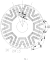
- first magnetic steel slot segment and the second magnetic steel slot segment form a V-shaped structure magnetic steel slot
- first magnetic steel slot segment, the second magnetic steel slot segment and the third magnetic steel slot segment form a U-shaped magnetic steel slot.
- a magnetic flux conducting path is formed between the outer layer magnetic steel slot and the inner layer magnetic steel slot; and the inner layer magnetic steel slot comprises a first inner layer magnetic steel slot segment, a second inner layer magnetic steel slot segment and a third inner layer magnetic steel slot segment arranged in sequence; the first inner layer magnetic steel slot segment, the second inner layer magnetic steel slot segment and the third inner layer magnetic steel slot segment are communicated with one after another to form a U-shaped structure with an opening toward the outer edge of the rotor body; or the first inner layer magnetic steel slot segment, the second inner layer magnetic steel slot segment and the third inner layer magnetic steel slot segment are arranged at intervals in sequence, and second magnetic barrier bridges are respectively formed between the first inner layer magnetic steel slot segment and the second inner layer magnetic steel slot segment which are adjacent, and between the second inner layer magnetic steel slot segment and the third inner layer magnetic steel slot segment which are adjacent.
- the outer layer magnetic steel slot of the magnetic steel slot group on the rotor body, more permanent magnets can be placed in a unit volume of the rotor, thereby generating a larger permanent magnet torque, improving a q-axis inductance of the motor, increasing efficiency of the motor, reducing torque ripples of the motor, reducing vibrations and noises of the motor, and improving an anti-demagnetization ability of the motor.
- first inner layer magnetic steel slot segment 121, the second inner layer magnetic steel slot segment 122 and the third inner layer magnetic steel slot segment 123 are arranged at intervals in sequence.
- Second magnetic barrier bridges are respectively formed between the first inner layer magnetic steel slot segment 121 and the second inner layer magnetic steel slot segment 122 which are adjacent, and the adjacent second inner layer magnetic steel slot segment 122 and third inner layer magnetic steel slot segment 123 which are adjacent.
- Each of the bent slots of the magnetic steel slot is configured to form an included angle, which can more effectively conduct a q-axis flux linkage of the stator 40 into each magnetic flux conducting path more evenly, thereby increasing the q-axis inductance of the motor, and increasing the reluctance torque of the motor.
- the rotor structure further includes an inner layer permanent magnet, and the inner layer permanent magnet is arranged in the inner layer magnetic steel slot. Such an arrangement facilitates an installation of the inner layer permanent magnet.
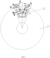
- a fifth included angle ⁇ 1 is formed between the direct axis of the rotor body and a straight line drawn between a center of the rotor body and a point, at which a side edge of the outer layer permanent magnet adjacent to the direct axis of the rotor body and a surface of the outer layer permanent magnet adjacent to an edge of the rotor body intersect.
- a sixth included angle ⁇ 2 is formed between the direct axis of the rotor body and a connecting straight line drawn between the center of the rotor body and a point, at which a side edge of the inner layer permanent magnet adjacent to the direct axis of the rotor body and a surface of the inner layer permanent magnet adjacent to the edge of the rotor body intersect.
- the working point of the permanent magnet can be better adjusted, so that the average working point of the inner layer permanent magnet and the outer layer permanent magnet is higher, and a ratio of the magnetic flux lines of the inner layer permanent magnet 30 entering the outer layer permanent magnet to magnetic flux lines of the inner layer permanent magnet directly entering the stator 40 is more reasonable, thereby increasing the permanent magnet flux linkage of the motor, and improving the efficiency and power factor of the motor.
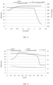
- the effect of the ratio of the surface area of the inner layer permanent magnet to the surface area of the outer layer permanent magnet on the flux linkage of the motor is shown in the figure.
- the ratio of the surface area of the inner layer permanent magnet to the surface area of the outer layer permanent magnet to satisfy 1.3 ⁇ sin ⁇ 1/sin ⁇ 2 ⁇ S1/S2 ⁇ 2 ⁇ sin ⁇ 1/sin ⁇ 2, a larger no-load flux linkage of the motor can be obtained.
- the permanent magnet of the motor rotor is a ferrite permanent magnet.
- An arc is drawn by taking the center of the rotor as a center and passes through a midpoint P of an outer sideline of the outermost layer permanent magnet. Along the arc, the sum of thicknesses of the permanent magnets of the rotor accounts for 45% -70% of the circumference of the arc..
- each layer permanent magnet slot in order to enhance the mechanical strength of the rotor, one or more magnetic barrier bridges are formed in each layer permanent magnet slot.
- the inner layer permanent magnet slot is provided with flat permanent magnets at two ends adjacent to the outer circle of the rotor
- the second layer permanent magnet slot is provided with flat permanent magnets at ends adjacent to the outer circle of the rotor.
- the thickness M 2 of the plate permanent magnets disposed at two sides of the innermost layer of the rotor is greater than the thickness M 1 of the plate permanent magnets disposed at the ends of the second layer, and 1.1 M 1 ⁇ M 2 ⁇ 1.8 M 1 is satisfied.
- the thickness M2 of the inner layer permanent magnet is designed to be greater than the thickness M1 of the outer layer permanent magnet.
- 1.1 ⁇ M 1 ⁇ M 2 ⁇ 1.8 ⁇ M 1 is satisfied.
- a magnetic flux conducting path formed by the inner layer rectangular permanent magnet and the outer layer rectangular permanent magnet has a variable width, and the width of part of the magnetic flux conducting path adjacent to the outer surface of the rotor is smaller. By configuring the width the magnetic flux conducting path to be gradually reduced, the magnetic flux areas of the inner layer permanent magnet and the outer layer permanent magnet can be better adjusted to achieve adjustment for consistency of the working points of the inner layer permanent magnet and the outer layer permanent magnet.
- an end of the outer layer permanent magnet slot of the rotor has a bent portion bending toward an end of the inner layer permanent magnet slot .
- Such an arrangement can better conduct the directions of the magnetic flux lines.
- a magnetic flux conducting path f 3 is formed between two innermost layers of magnetic steel slots of adjacent two magnetic poles; a magnetic flux conducting path f 2 is formed between the innermost layer magnetic steel slot and a second layer magnetic steel slot; and a magnetic flux conducting path f 1 is formed in a magnetic conduction region between the second layer magnetic steel slot and the outer circle of the rotor.
- an end of the magnetic flux conducting path is configured to bend toward the inner layer permanent magnet 30.
- the distribution of the q-axis magnetic flux lines f of the motor is shown in FIG. 7 .
- 0.6 M ⁇ D3 is satisfied, where D3 denotes a distance between a midpoint of an end edge of the bent second layer magnetic steel slot and a midpoint of an end edge of the pre-bending second layer magnetic steel slot, and M denotes the width of the unbent portion of the second layer magnetic steel slot adjacent to the end of the rotor.
- Ga denotes a distance between the end point of the end edge of the bent second layer magnetic steel slot adjacent to the outer side and the end point of the end edge of the pre-bending second layer magnetic steel slot adjacent to the inner side, and the distance Ga is approximately an integer multiple of an air gap length g between the stator and the rotor.
- the length of the bent portion at the end of the second layer magnetic steel slot is H-H 1
- the width of the end of the unbent portion of the magnetic steel slot is M
- 0.4 ⁇ M ⁇ ( H-H1 ) is satisfied.
- H denotes the distance from the outer edge of the bent portion of the magnetic steel slot to the outer circle of the rotor
- H 1 denotes a thickness of the magnetic barrier bridge formed between the bent portion of the magnetic steel slot of the rotor and the outer circle of the rotor
- M denotes the width of the end of the unbent portion of the magnetic steel slot.
Landscapes
- Engineering & Computer Science (AREA)
- Power Engineering (AREA)
- Permanent Field Magnets Of Synchronous Machinery (AREA)
- Iron Core Of Rotating Electric Machines (AREA)
- Synchronous Machinery (AREA)
Claims (12)
- Rotorstruktur, Folgendes umfassend:einen Rotorhauptteil (10), wobei der Rotorhauptteil (10) mit einer Magnetstahlschlitzgruppe versehen ist, wobei die Magnetstahlschlitzgruppe einen Außenschicht-Magnetstahlschlitz (11) umfasst, wobei der Außenschicht-Magnetstahlschlitz (11) mehrere Magnetstahlschlitzsegmente umfasst, undmindestens zwei der mehreren Magnetstahlschlitzsegmente in einer radialen Richtung des Rotorhauptteils (10) und an beiden Seiten einer Längsachse des Rotorhauptteils (10) gegenüberliegend angeordnet sind, undeinen Außenschicht-Dauermagneten (20), wobei der Außenschicht-Dauermagnet (20) in einem der mindestens zwei der mehreren Magnetstahlschlitzsegmente angeordnet ist, eine Länge des Außenschicht-Dauermagneten (20) eine Länge L in einem Querschnitt der Rotorstruktur ist, eine maximale Distanz zwischen den zwei gegenüberliegend angeordneten Magnetstahlschlitzsegmenten C ist und 0,8 x C ≤ L ist, wobei die mehreren Magnetstahlschlitzsegmente Folgendes umfassen:ein erstes Magnetstahlschlitzsegment (111), wobei sich ein erstes Ende des ersten Magnetstahlschlitzsegments (111) hin zu einer Rotationswellenöffnung (13) des Rotorhauptteils (10) erstreckt, sich ein zweites Ende des ersten Magnetstahlschlitzsegments (111) hin zu einem Außenrand des Rotorhauptteils (10) erstreckt und das erste Magnetstahlschlitzsegment (111) an einer ersten Seite der Längsachse angeordnet ist, undein zweites Magnetstahlschlitzsegment (112), wobei das zweite Magnetstahlschlitzsegment (112) gegenüber dem ersten Magnetstahlschlitzsegment (111) angeordnet ist und an einer zweiten Seite gegenüber der ersten Seite der Längsachse angeordnet ist, wobei sich ein erstes Ende des zweiten Magnetstahlschlitzsegments (112) hin zu der Rotationswellenöffnung (13) erstreckt, sich ein zweites Ende des zweiten Magnetstahlschlitzsegments (112) hin zu einem Außenrand des Rotorhauptteils (10) erstreckt,wobei der Außenschicht-Magnetstahlschlitz (11) ferner Folgendes umfasst:einen ersten Schlitz (113), der relativ zu dem ersten Magnetstahlschlitzsegment (111) gebogen ist, wobei ein erstes Ende des ersten Schlitzes (113) mit dem zweiten Ende des ersten Magnetstahlschlitzsegments (111) in Verbindung steht und sich ein zweites Ende des ersten Schlitzes (113) hin zum Außenrand des Rotorhauptteils (10) erstreckt und sich allmählich einer Quadraturachse des Rotorhauptteils (10) nähert, undeinen zweiten Schlitz (114), der relativ zu dem zweiten Magnetstahlschlitzsegment (112) gebogen ist, wobei ein erstes Ende des zweiten Schlitzes (114) mit dem zweiten Ende des zweiten Magnetstahlschlitzsegments (112) in Verbindung steht und sich ein zweites Ende des zweiten Schlitzes (114) hin zum Außenrand des Rotorhauptteils (10) erstreckt und sich allmählich einer weiteren Quadraturachse des Rotorhauptteils (10) nähert, undwobei eine Breite des ersten Schlitzes (113) und/oder des zweiten Schlitzes (114) in einer radialen Richtung des Rotorhauptteils (10) nach außen allmählich abnimmt,wobei die Magnetstahlschlitzgruppe ferner einen Innenschicht-Magnetstahlschlitz (12) umfasst, wobei der Innenschicht-Magnetstahlschlitz (12) an einer Innenseite des Außenschicht-Magnetstahlschlitzes (11) und angrenzend an die Rotationswellenöffnung (13) angeordnet ist,dadurch gekennzeichnet, dass D3 eine Distanz von einem Mittelpunkt einer Seitenwand des zweiten Endes des ersten Schlitzes (113), die an den Außenrand des Rotorhauptteils (10) grenzt, zu einem Schnittpunkt einer Verlängerungslinie einer geometrischen Mittellinie des ersten Magnetstahlschlitzsegments (111) von dem ersten Ende zu dem zweiten Ende des ersten Magnetstahlschlitzsegments (111) und einem Außenrand des Rotorhauptteils (10), der an das zweite Ende des ersten Schlitzes (113) grenzt, bezeichnet und M eine Breite des zweiten Endes des ersten Magnetstahlschlitzsegments (111) bezeichnet, wobei 0,6M ≤ D3 ist.
- Rotorstruktur nach Anspruch 1, dadurch gekennzeichnet, dass die mehreren Magnetstahlschlitzsegmente ferner ein drittes Magnetstahlschlitzsegment (115) umfassen, wobei:
ein erstes Ende des dritten Magnetstahlschlitzsegments (115) in Verbindung mit dem ersten Ende des ersten Magnetstahlschlitzsegments (111) steht und ein zweites Ende des dritten Magnetstahlschlitzsegments (115) in Verbindung mit dem ersten Ende des zweiten Magnetstahlschlitzsegments (112) steht. - Rotorstruktur nach Anspruch 2, dadurch gekennzeichnet, dass das erste Magnetstahlschlitzsegment (111) und das zweite Magnetstahlschlitzsegment (112) einen Magnetstahlschlitz mit V-förmiger Struktur bilden, oder
dass das erste Magnetstahlschlitzsegment (111), das zweite Magnetstahlschlitzsegment (112) und das dritte Magnetstahlschlitzsegment (115) einen Magnetstahlschlitz mit U-förmiger Struktur bilden. - Rotorstruktur nach Anspruch 1, dadurch gekennzeichnet, dass zwischen dem zweiten Ende des ersten Schlitzes (113) und dem Außenrand des Rotorhauptteils (10) eine erste Magnetsperrenüberbrückung gebildet ist, 0,4 x M ≤ (H - H1) oder 0,4 x M ≤ (H - H1) ≤ 2 x M, wobei M die Breite des zweiten Endes des ersten Magnetstahlschlitzsegments (111) bezeichnet, H eine Distanz von dem zweiten Ende des ersten Magnetstahlschlitzsegments (111) zu dem Außenrand des Rotorhauptteils (10) bezeichnet und H1 eine Breite der ersten Magnetsperrenüberbrückung von dem zweiten Ende des ersten Schlitzes (113) zu dem Außenumfang des Rotors bezeichnet.
- Rotorstruktur nach Anspruch 1, dadurch gekennzeichnet, dass 0,25 x M ≤ D1 ≤ 08 x M oder 0,3 x M ≤ D1 ≤ 0,45 x M, wobei M die Breite des zweiten Endes des ersten Magnetstahlschlitzsegments (111) bezeichnet und D1 eine Breite des zweiten Endes des ersten Schlitzes (1139 bezeichnet.
- Rotorstruktur nach Anspruch 1, dadurch gekennzeichnet, dass zwischen dem Außenschicht-Magnetstahlschlitz (11) und dem Innenschicht-Magnetstahlschlitz (12) ein Magnetflussleitweg gebildet ist und der Innenschicht-Magnetstahlschlitz (12) ein erstes Innenschicht-Magnetstahlschlitzsegment (121), eine zweites Innenschicht-Magnetstahlschlitzsegment (122) und ein drittes Innenschicht-Magnetstahlschlitzsegment (123) umfasst, die in Folge angeordnet sind,wobei das erste Innenschicht-Magnetstahlschlitzsegment (121), das zweite Innenschicht-Magnetstahlschlitzsegment (122) und das dritte Innenschicht-Magnetstahlschlitzsegment (123) nacheinander in Verbindung gebracht sind, um eine U-förmige Struktur mit einer Öffnung hin zu dem Außenrand des Rotorhauptteils (10) zu bilden, oderdas erste Innenschicht-Magnetstahlschlitzsegment (121), das zweite Innenschicht-Magnetstahlschlitzsegment (122) und das dritte Innenschicht-Magnetstahlschlitzsegment (123) in Folge in Intervallen angeordnet sind und zwischen dem ersten Innenschicht-Magnetstahlschlitzsegment (121) und dem zweiten Innenschicht-Magnetstahlschlitzsegment (122), die aneinander angrenzen, und zwischen dem zweiten Innenschicht-Magnetstahlschlitzsegment (122) und dem dritten Innenschicht-Magnetstahlschlitzsegment (123), die aneinander angrenzen, jeweils zweite Magnetsperrenüberbrückungen angeordnet sind.
- Rotorstruktur nach Anspruch 6, dadurch gekennzeichnet, dassdas erste Innenschicht-Magnetstahlschlitzsegment (121) einen dritten Schlitz (124) umfasst, der relativ zu dem ersten Innenschicht-Magnetstahlschlitzsegment (121) gebogen ist, wobei ein erstes Ende des dritten Schlitzes (124) in Verbindung mit einem Ende des ersten Innenschicht-Magnetstahlschlitzsegments (121) steht, das an den Außenrand des Rotorhauptteils (10) grenzt, und sich ein zweites Ende des dritten Schlitzes (124) hin zum Außenrand des Rotorhauptteils (10) erstreckt und sich allmählich einer Quadraturachse nähert,das dritte Innenschicht-Magnetstahlschlitzsegment (123) einen vierten Schlitz (125) umfasst, der relativ zu dem dritten Innenschicht-Magnetstahlschlitzsegment (123) gebogen ist, wobei ein erstes Ende des vierten Schlitzes (125) in Verbindung mit einem Ende des dritten Innenschicht-Magnetstahlschlitzsegments (123) steht, das an den Außenrand des Rotorhauptteils (10) grenzt, und sich ein zweites Ende des vierten Schlitzes (125) hin zum Außenrand des Rotorhauptteils (10) erstreckt und sich allmählich der anderen Quadraturachse nähert.
- Rotorstruktur nach Anspruch 1, dadurch gekennzeichnet, dass zwischen Verlängerungslinien von Seitenwänden des ersten Schlitzes (113) und des zweiten Schlitzes (114) ein eingeschlossener Winkel A1 gebildet ist, wobei die Seitenwände des ersten Schlitzes (113) und des zweiten Schlitzes (114) an die Längsachse grenzen, dass zwischen Verlängerungslinien von Seitenwänden des ersten Magnetstahlschlitzsegments (111) und des zweiten Magnetstahlschlitzsegments (112) ein eingeschlossener Winkel A gebildet ist und die Seitenwände des ersten Magnetstahlschlitzsegments (111) und des zweiten Magnetstahlschlitzsegments (112) an die Längsachse grenzen, wobei 2 x A ≤ A1.
- Rotorstruktur nach Anspruch 7, dadurch gekennzeichnet, dass zwischen Verlängerungslinien von Seitenwänden des dritten Schlitzes (124) und des vierten Schlitzes (125) ein eingeschlossener Winkel B1 gebildet ist, wobei die Seitenwände des dritten Schlitzes (124) und des vierten Schlitzes (125) an die Längsachse grenzen, dass zwischen den Verlängerungslinien von Seitenwänden des ersten Innenschicht-Magnetstahlschlitzsegments (121) und des dritten Innenschicht-Magnetstahlschlitzsegments (123) ein eingeschlossener Winkel B gebildet ist, wobei die Seitenwände des ersten Innenschicht-Magnetstahlschlitzsegments (121) und des dritten Innenschicht-Magnetstahlschlitzsegments (123) an die Längsachse grenzen, wobei 2 x B ≤ B1 ist, und

- Rotorstruktur nach Anspruch 7, dadurch gekennzeichnet, dass die Rotorstruktur ferner einen Innenschicht-Dauermagneten (30) umfasst und der Innenschicht-Dauermagnet (30) in dem Innenschicht-Magnetstahlschlitz (12) angeordnet ist, zwischen der Längsachse des Rotorhauptteils (10) und einer geraden Linie, die zwischen einer Mitte des Rotorhauptteils (10) und einem Punkt gezogen ist, an dem sich ein Seitenrand des Außenschicht-Dauermagneten (20), der an die Längsachse des Rotorhauptteils (10) grenzt, und eine Oberfläche des Außenschicht-Dauermagneten, die an einen Rand des Rotorhauptteils (10) grenzt, schneiden, ein fünfter eingeschlossener Winkel α1 gebildet ist, und zwischen der Längsachse des Rotorhauptteils und einer geraden Line, die zwischen der Mitte des Rotorhauptteils (10) und einem Punkt gezogen ist, an dem sich ein Seitenrand des Innenschicht-Dauermagneten (30), der an die Längsachse des Rotorhauptteils (10) grenzt, und eine Oberfläche des Innenschicht-Dauermagneten, die an den Rand des Rotorhauptteils (10) grenzt, schneiden, ein sechster eingeschlossener Winkel α2 gebildet ist, wobei 1,3 x (sinα1 / sinα2) ≤ S1 / S2 ≤ 2 x (sinα1 / sinα2), wobei S1 einen Flächeninhalt einer Seite des Außenschicht-Dauermagneten (20) bezeichnet, die an die Längsachse des Rotorhauptteils (10) grenzt, und S2 einen Flächeninhalt einer Seite des Innenschicht-Dauermagneten (30) bezeichnet, die an die Längsachse des Rotorhauptteils (10) grenzt, oder 1,5 x (sinα1 / sinα2) ≤ S1 / S2 ≤ 1,8 x (sinα1 / sinα2).
- Dauermagnet-Hilfssynchronreluktanzmotor, eine Rotorstruktur umfassend, dadurch gekennzeichnet ist, dass die Rotorstruktur die Rotorstruktur nach einem der Ansprüche 1 bis 10 ist.
- Elektrofahrzeug, eine Rotorstruktur umfassend, dadurch gekennzeichnet ist, dass die Rotorstruktur die Rotorstruktur nach einem der Ansprüche 1 bis 10 ist.
Applications Claiming Priority (2)
| Application Number | Priority Date | Filing Date | Title |
|---|---|---|---|
| CN201810219481.3A CN108336844B (zh) | 2018-03-16 | 2018-03-16 | 转子结构、永磁辅助同步磁阻电机及电动汽车 |
| PCT/CN2018/119873 WO2019174324A1 (zh) | 2018-03-16 | 2018-12-07 | 转子结构、永磁辅助同步磁阻电机及电动汽车 |
Publications (3)
| Publication Number | Publication Date |
|---|---|
| EP3767796A1 EP3767796A1 (de) | 2021-01-20 |
| EP3767796A4 EP3767796A4 (de) | 2021-04-28 |
| EP3767796B1 true EP3767796B1 (de) | 2025-07-02 |
Family
ID=62932057
Family Applications (1)
| Application Number | Title | Priority Date | Filing Date |
|---|---|---|---|
| EP18910125.6A Active EP3767796B1 (de) | 2018-03-16 | 2018-12-07 | Rotorstruktur, permanentmagnet-synchronreluktanzhilfsmotor und elektrofahrzeug |
Country Status (5)
| Country | Link |
|---|---|
| US (1) | US11705767B2 (de) |
| EP (1) | EP3767796B1 (de) |
| CN (1) | CN108336844B (de) |
| DK (1) | DK3767796T3 (de) |
| WO (1) | WO2019174324A1 (de) |
Families Citing this family (6)
| Publication number | Priority date | Publication date | Assignee | Title |
|---|---|---|---|---|
| CN108336844B (zh) | 2018-03-16 | 2020-10-23 | 珠海格力节能环保制冷技术研究中心有限公司 | 转子结构、永磁辅助同步磁阻电机及电动汽车 |
| CN108566006A (zh) * | 2018-03-16 | 2018-09-21 | 珠海格力节能环保制冷技术研究中心有限公司 | 转子结构、永磁辅助同步磁阻电机及电动汽车 |
| CN108336845B (zh) | 2018-03-16 | 2020-11-03 | 珠海格力节能环保制冷技术研究中心有限公司 | 转子结构、永磁辅助同步磁阻电机及电动汽车 |
| CN112186921B (zh) * | 2019-07-04 | 2025-07-15 | 谷轮环境科技(苏州)有限公司 | 用于异步起动永磁电机的转子及异步起动永磁电机 |
| CN111146888A (zh) * | 2019-12-09 | 2020-05-12 | 珠海格力电器股份有限公司 | 转子冲片、转子铁芯、永磁电机和电动汽车 |
| CN112510950B (zh) * | 2020-11-18 | 2025-05-09 | 苏州英磁新能源科技有限公司 | 一种盘式电机磁钢布置方式 |
Citations (1)
| Publication number | Priority date | Publication date | Assignee | Title |
|---|---|---|---|---|
| US20170187257A1 (en) * | 2015-12-29 | 2017-06-29 | Danfoss (Tianjin) Ltd. | Motor |
Family Cites Families (24)
| Publication number | Priority date | Publication date | Assignee | Title |
|---|---|---|---|---|
| US6008559A (en) * | 1997-07-22 | 1999-12-28 | Matsushita Electric Industrial Co., Ltd. | Motor using a rotor including an interior permanent magnet |
| US6815859B2 (en) * | 2001-03-07 | 2004-11-09 | Aisin Seiki Kabushiki Kaisha | Synchronous reluctance motor |
| JP2002320363A (ja) * | 2001-04-20 | 2002-10-31 | Denso Corp | 車両用発電電動機 |
| JP2002354727A (ja) | 2001-05-21 | 2002-12-06 | Hitachi Ltd | 永久磁石を埋設した回転子および回転電機 |
| JP5059614B2 (ja) * | 2004-10-26 | 2012-10-24 | コルモーゲン コーポレイション | 永久磁石埋め込み型ロータにおける磁石およびウエブの構成 |
| EP2304863B1 (de) * | 2008-07-30 | 2018-06-27 | Regal Beloit America, Inc. | Motor mit inneren permanentmagneten mit rotor mit ungleichen polen |
| JP2013066339A (ja) * | 2011-09-20 | 2013-04-11 | Toshiba Corp | 埋め込み磁石型回転電機 |
| CN103023256B (zh) * | 2011-09-26 | 2017-03-01 | 辐射通量实验室私人有限公司 | 永磁电机 |
| JP5752272B2 (ja) * | 2011-12-26 | 2015-07-22 | 三菱電機株式会社 | 回転子およびモータ |
| CN102664475A (zh) * | 2012-05-14 | 2012-09-12 | 上海特波电机有限公司 | 无刷电机的低波动内置式永磁转子 |
| US8664823B2 (en) * | 2012-05-30 | 2014-03-04 | GM Global Technology Operations LLC | Magnetic barrier for minimizing demagnetization in bi-permanent magnet synchronous machines |
| US20140028139A1 (en) | 2012-07-26 | 2014-01-30 | Colin Hamer | Permanent magnet rotor with resin-covered magnet and lamination for thermal control |
| CN203219023U (zh) * | 2012-12-10 | 2013-09-25 | 艾默生环境优化技术(苏州)有限公司 | 电机转子 |
| CN103280904A (zh) * | 2013-05-03 | 2013-09-04 | 苏州和鑫电气股份有限公司 | 电动汽车用双层v型内置式永磁电机转子 |
| US9479017B2 (en) * | 2014-07-22 | 2016-10-25 | GM Global Technology Operations LLC | Deep V-magnet cavity structure rotor |
| CN204992999U (zh) * | 2015-07-24 | 2016-01-20 | 西安正麒电气有限公司 | 一种内置式永磁电机转子冲片 |
| CN205566051U (zh) * | 2015-12-29 | 2016-09-07 | 丹佛斯(天津)有限公司 | 电动机 |
| EP3261220B1 (de) * | 2016-06-23 | 2020-08-12 | Volvo Car Corporation | Elektrische maschine |
| DE102016212022A1 (de) * | 2016-07-01 | 2018-01-04 | Volkswagen Aktiengesellschaft | Rotor |
| CN106026597B (zh) * | 2016-07-11 | 2018-08-21 | 江苏大学 | 内置磁障式磁场增强型永磁无刷电机 |
| CN106787316A (zh) * | 2016-12-22 | 2017-05-31 | 温岭市九洲电机制造有限公司 | 一种永磁电机的冲片结构 |
| CN206850538U (zh) * | 2017-04-28 | 2018-01-05 | 浙江钜丰冲压科技有限公司 | 一种定转子冲片机构 |
| CN108336844B (zh) * | 2018-03-16 | 2020-10-23 | 珠海格力节能环保制冷技术研究中心有限公司 | 转子结构、永磁辅助同步磁阻电机及电动汽车 |
| CN208316435U (zh) * | 2018-03-16 | 2019-01-01 | 珠海格力节能环保制冷技术研究中心有限公司 | 转子结构、永磁辅助同步磁阻电机及电动汽车 |
-
2018
- 2018-03-16 CN CN201810219481.3A patent/CN108336844B/zh active Active
- 2018-12-07 US US16/980,350 patent/US11705767B2/en active Active
- 2018-12-07 EP EP18910125.6A patent/EP3767796B1/de active Active
- 2018-12-07 DK DK18910125.6T patent/DK3767796T3/da active
- 2018-12-07 WO PCT/CN2018/119873 patent/WO2019174324A1/zh not_active Ceased
Patent Citations (1)
| Publication number | Priority date | Publication date | Assignee | Title |
|---|---|---|---|---|
| US20170187257A1 (en) * | 2015-12-29 | 2017-06-29 | Danfoss (Tianjin) Ltd. | Motor |
Also Published As
| Publication number | Publication date |
|---|---|
| DK3767796T3 (da) | 2025-09-22 |
| CN108336844A (zh) | 2018-07-27 |
| EP3767796A4 (de) | 2021-04-28 |
| EP3767796A1 (de) | 2021-01-20 |
| US11705767B2 (en) | 2023-07-18 |
| CN108336844B (zh) | 2020-10-23 |
| WO2019174324A1 (zh) | 2019-09-19 |
| US20210257869A1 (en) | 2021-08-19 |
Similar Documents
| Publication | Publication Date | Title |
|---|---|---|
| EP3767795B1 (de) | Rotorstruktur, permanentmagnet-synchronreluktanzhilfsmotor und elektrofahrzeug | |
| EP3767796B1 (de) | Rotorstruktur, permanentmagnet-synchronreluktanzhilfsmotor und elektrofahrzeug | |
| US11637464B2 (en) | Rotor structure, permanent magnet auxiliary synchronous reluctance motor and electric vehicle | |
| EP2741400B1 (de) | Motorrotor und motor damit | |
| US11799333B2 (en) | Permanent magnet auxiliary synchronous reluctance motor and electric vehicle provided with same | |
| EP2741402B1 (de) | Motor und rotor dafür | |
| EP3329577B1 (de) | Synchroner permanentmagnetmotor | |
| EP3767797B1 (de) | Rotorstruktur, permanentmagnet-synchronreluktanzhilfsmotor und elektrofahrzeug | |
| EP3534496A1 (de) | Dauermagnetmotor | |
| EP3767792A1 (de) | Rotorstruktur, permanentmagnet-synchronreluktanzhilfsmotor und elektrofahrzeug | |
| WO2024078113A1 (zh) | 永磁辅助同步磁阻电机及压缩机 |
Legal Events
| Date | Code | Title | Description |
|---|---|---|---|
| STAA | Information on the status of an ep patent application or granted ep patent |
Free format text: STATUS: THE INTERNATIONAL PUBLICATION HAS BEEN MADE |
|
| PUAI | Public reference made under article 153(3) epc to a published international application that has entered the european phase |
Free format text: ORIGINAL CODE: 0009012 |
|
| STAA | Information on the status of an ep patent application or granted ep patent |
Free format text: STATUS: REQUEST FOR EXAMINATION WAS MADE |
|
| 17P | Request for examination filed |
Effective date: 20200924 |
|
| AK | Designated contracting states |
Kind code of ref document: A1 Designated state(s): AL AT BE BG CH CY CZ DE DK EE ES FI FR GB GR HR HU IE IS IT LI LT LU LV MC MK MT NL NO PL PT RO RS SE SI SK SM TR |
|
| AX | Request for extension of the european patent |
Extension state: BA ME |
|
| A4 | Supplementary search report drawn up and despatched |
Effective date: 20210331 |
|
| RIC1 | Information provided on ipc code assigned before grant |
Ipc: H02K 1/27 20060101AFI20210325BHEP Ipc: H02K 29/03 20060101ALI20210325BHEP |
|
| DAV | Request for validation of the european patent (deleted) | ||
| DAX | Request for extension of the european patent (deleted) | ||
| STAA | Information on the status of an ep patent application or granted ep patent |
Free format text: STATUS: EXAMINATION IS IN PROGRESS |
|
| 17Q | First examination report despatched |
Effective date: 20230313 |
|
| P01 | Opt-out of the competence of the unified patent court (upc) registered |
Effective date: 20230530 |
|
| REG | Reference to a national code |
Ref country code: DE Free format text: PREVIOUS MAIN CLASS: H02K0001270000 Ipc: H02K0001276000 Ref country code: DE Ref legal event code: R079 Ref document number: 602018083316 Country of ref document: DE Free format text: PREVIOUS MAIN CLASS: H02K0001270000 Ipc: H02K0001276000 |
|
| GRAP | Despatch of communication of intention to grant a patent |
Free format text: ORIGINAL CODE: EPIDOSNIGR1 |
|
| STAA | Information on the status of an ep patent application or granted ep patent |
Free format text: STATUS: GRANT OF PATENT IS INTENDED |
|
| RIC1 | Information provided on ipc code assigned before grant |
Ipc: H02K 29/03 20060101ALI20250317BHEP Ipc: H02K 1/276 20220101AFI20250317BHEP |
|
| INTG | Intention to grant announced |
Effective date: 20250327 |
|
| GRAS | Grant fee paid |
Free format text: ORIGINAL CODE: EPIDOSNIGR3 |
|
| GRAA | (expected) grant |
Free format text: ORIGINAL CODE: 0009210 |
|
| STAA | Information on the status of an ep patent application or granted ep patent |
Free format text: STATUS: THE PATENT HAS BEEN GRANTED |
|
| AK | Designated contracting states |
Kind code of ref document: B1 Designated state(s): AL AT BE BG CH CY CZ DE DK EE ES FI FR GB GR HR HU IE IS IT LI LT LU LV MC MK MT NL NO PL PT RO RS SE SI SK SM TR |
|
| REG | Reference to a national code |
Ref country code: GB Ref legal event code: FG4D |
|
| REG | Reference to a national code |
Ref country code: CH Ref legal event code: EP |
|
| REG | Reference to a national code |
Ref country code: DE Ref legal event code: R096 Ref document number: 602018083316 Country of ref document: DE |
|
| REG | Reference to a national code |
Ref country code: IE Ref legal event code: FG4D |
|
| REG | Reference to a national code |
Ref country code: DK Ref legal event code: T3 Effective date: 20250917 |
|
| REG | Reference to a national code |
Ref country code: NL Ref legal event code: MP Effective date: 20250702 |
|
| PG25 | Lapsed in a contracting state [announced via postgrant information from national office to epo] |
Ref country code: PT Free format text: LAPSE BECAUSE OF FAILURE TO SUBMIT A TRANSLATION OF THE DESCRIPTION OR TO PAY THE FEE WITHIN THE PRESCRIBED TIME-LIMIT Effective date: 20251103 |
|
| PG25 | Lapsed in a contracting state [announced via postgrant information from national office to epo] |
Ref country code: NL Free format text: LAPSE BECAUSE OF FAILURE TO SUBMIT A TRANSLATION OF THE DESCRIPTION OR TO PAY THE FEE WITHIN THE PRESCRIBED TIME-LIMIT Effective date: 20250702 |
|
| REG | Reference to a national code |
Ref country code: AT Ref legal event code: MK05 Ref document number: 1810411 Country of ref document: AT Kind code of ref document: T Effective date: 20250702 |
|
| PG25 | Lapsed in a contracting state [announced via postgrant information from national office to epo] |
Ref country code: IS Free format text: LAPSE BECAUSE OF FAILURE TO SUBMIT A TRANSLATION OF THE DESCRIPTION OR TO PAY THE FEE WITHIN THE PRESCRIBED TIME-LIMIT Effective date: 20251102 |
|
| PGFP | Annual fee paid to national office [announced via postgrant information from national office to epo] |
Ref country code: GB Payment date: 20251201 Year of fee payment: 8 |
|
| PG25 | Lapsed in a contracting state [announced via postgrant information from national office to epo] |
Ref country code: NO Free format text: LAPSE BECAUSE OF FAILURE TO SUBMIT A TRANSLATION OF THE DESCRIPTION OR TO PAY THE FEE WITHIN THE PRESCRIBED TIME-LIMIT Effective date: 20251002 |
|
| REG | Reference to a national code |
Ref country code: LT Ref legal event code: MG9D |
|
| PG25 | Lapsed in a contracting state [announced via postgrant information from national office to epo] |
Ref country code: AT Free format text: LAPSE BECAUSE OF FAILURE TO SUBMIT A TRANSLATION OF THE DESCRIPTION OR TO PAY THE FEE WITHIN THE PRESCRIBED TIME-LIMIT Effective date: 20250702 |
|
| PG25 | Lapsed in a contracting state [announced via postgrant information from national office to epo] |
Ref country code: FI Free format text: LAPSE BECAUSE OF FAILURE TO SUBMIT A TRANSLATION OF THE DESCRIPTION OR TO PAY THE FEE WITHIN THE PRESCRIBED TIME-LIMIT Effective date: 20250702 |
|
| PGFP | Annual fee paid to national office [announced via postgrant information from national office to epo] |
Ref country code: DK Payment date: 20251201 Year of fee payment: 8 |
|
| PG25 | Lapsed in a contracting state [announced via postgrant information from national office to epo] |
Ref country code: HR Free format text: LAPSE BECAUSE OF FAILURE TO SUBMIT A TRANSLATION OF THE DESCRIPTION OR TO PAY THE FEE WITHIN THE PRESCRIBED TIME-LIMIT Effective date: 20250702 |
|
| PGFP | Annual fee paid to national office [announced via postgrant information from national office to epo] |
Ref country code: FR Payment date: 20251201 Year of fee payment: 8 |
|
| PG25 | Lapsed in a contracting state [announced via postgrant information from national office to epo] |
Ref country code: GR Free format text: LAPSE BECAUSE OF FAILURE TO SUBMIT A TRANSLATION OF THE DESCRIPTION OR TO PAY THE FEE WITHIN THE PRESCRIBED TIME-LIMIT Effective date: 20251003 |
|
| PG25 | Lapsed in a contracting state [announced via postgrant information from national office to epo] |
Ref country code: SE Free format text: LAPSE BECAUSE OF FAILURE TO SUBMIT A TRANSLATION OF THE DESCRIPTION OR TO PAY THE FEE WITHIN THE PRESCRIBED TIME-LIMIT Effective date: 20250702 Ref country code: CZ Free format text: LAPSE BECAUSE OF FAILURE TO SUBMIT A TRANSLATION OF THE DESCRIPTION OR TO PAY THE FEE WITHIN THE PRESCRIBED TIME-LIMIT Effective date: 20250702 |
|
| PG25 | Lapsed in a contracting state [announced via postgrant information from national office to epo] |
Ref country code: LV Free format text: LAPSE BECAUSE OF FAILURE TO SUBMIT A TRANSLATION OF THE DESCRIPTION OR TO PAY THE FEE WITHIN THE PRESCRIBED TIME-LIMIT Effective date: 20250702 |
|
| PG25 | Lapsed in a contracting state [announced via postgrant information from national office to epo] |
Ref country code: BG Free format text: LAPSE BECAUSE OF FAILURE TO SUBMIT A TRANSLATION OF THE DESCRIPTION OR TO PAY THE FEE WITHIN THE PRESCRIBED TIME-LIMIT Effective date: 20250702 Ref country code: PL Free format text: LAPSE BECAUSE OF FAILURE TO SUBMIT A TRANSLATION OF THE DESCRIPTION OR TO PAY THE FEE WITHIN THE PRESCRIBED TIME-LIMIT Effective date: 20250702 |
|
| PG25 | Lapsed in a contracting state [announced via postgrant information from national office to epo] |
Ref country code: RS Free format text: LAPSE BECAUSE OF FAILURE TO SUBMIT A TRANSLATION OF THE DESCRIPTION OR TO PAY THE FEE WITHIN THE PRESCRIBED TIME-LIMIT Effective date: 20251002 |
|
| PG25 | Lapsed in a contracting state [announced via postgrant information from national office to epo] |
Ref country code: ES Free format text: LAPSE BECAUSE OF FAILURE TO SUBMIT A TRANSLATION OF THE DESCRIPTION OR TO PAY THE FEE WITHIN THE PRESCRIBED TIME-LIMIT Effective date: 20250702 |
|
| PG25 | Lapsed in a contracting state [announced via postgrant information from national office to epo] |
Ref country code: RO Free format text: LAPSE BECAUSE OF FAILURE TO SUBMIT A TRANSLATION OF THE DESCRIPTION OR TO PAY THE FEE WITHIN THE PRESCRIBED TIME-LIMIT Effective date: 20250702 |
|
| PG25 | Lapsed in a contracting state [announced via postgrant information from national office to epo] |
Ref country code: SM Free format text: LAPSE BECAUSE OF FAILURE TO SUBMIT A TRANSLATION OF THE DESCRIPTION OR TO PAY THE FEE WITHIN THE PRESCRIBED TIME-LIMIT Effective date: 20250702 |
|
| PGFP | Annual fee paid to national office [announced via postgrant information from national office to epo] |
Ref country code: DE Payment date: 20251222 Year of fee payment: 8 |
|
| PG25 | Lapsed in a contracting state [announced via postgrant information from national office to epo] |
Ref country code: IT Free format text: LAPSE BECAUSE OF FAILURE TO SUBMIT A TRANSLATION OF THE DESCRIPTION OR TO PAY THE FEE WITHIN THE PRESCRIBED TIME-LIMIT Effective date: 20250702 |
|
| PG25 | Lapsed in a contracting state [announced via postgrant information from national office to epo] |
Ref country code: SK Free format text: LAPSE BECAUSE OF FAILURE TO SUBMIT A TRANSLATION OF THE DESCRIPTION OR TO PAY THE FEE WITHIN THE PRESCRIBED TIME-LIMIT Effective date: 20250702 Ref country code: EE Free format text: LAPSE BECAUSE OF FAILURE TO SUBMIT A TRANSLATION OF THE DESCRIPTION OR TO PAY THE FEE WITHIN THE PRESCRIBED TIME-LIMIT Effective date: 20250702 |