EP3767768A1 - Connection structure for connecting power cable and conductor lead-out rod, and connection device for connecting power cable and conductor lead-out rod - Google Patents
Connection structure for connecting power cable and conductor lead-out rod, and connection device for connecting power cable and conductor lead-out rod Download PDFInfo
- Publication number
- EP3767768A1 EP3767768A1 EP19767484.9A EP19767484A EP3767768A1 EP 3767768 A1 EP3767768 A1 EP 3767768A1 EP 19767484 A EP19767484 A EP 19767484A EP 3767768 A1 EP3767768 A1 EP 3767768A1
- Authority
- EP
- European Patent Office
- Prior art keywords
- conductor
- conductor part
- out rod
- adapter
- conducting
- Prior art date
- Legal status (The legal status is an assumption and is not a legal conclusion. Google has not performed a legal analysis and makes no representation as to the accuracy of the status listed.)
- Granted
Links
Images




Classifications
-
- H—ELECTRICITY
- H01—ELECTRIC ELEMENTS
- H01R—ELECTRICALLY-CONDUCTIVE CONNECTIONS; STRUCTURAL ASSOCIATIONS OF A PLURALITY OF MUTUALLY-INSULATED ELECTRICAL CONNECTING ELEMENTS; COUPLING DEVICES; CURRENT COLLECTORS
- H01R4/00—Electrically-conductive connections between two or more conductive members in direct contact, i.e. touching one another; Means for effecting or maintaining such contact; Electrically-conductive connections having two or more spaced connecting locations for conductors and using contact members penetrating insulation
- H01R4/56—Electrically-conductive connections between two or more conductive members in direct contact, i.e. touching one another; Means for effecting or maintaining such contact; Electrically-conductive connections having two or more spaced connecting locations for conductors and using contact members penetrating insulation one conductor screwing into another
-
- H—ELECTRICITY
- H02—GENERATION; CONVERSION OR DISTRIBUTION OF ELECTRIC POWER
- H02G—INSTALLATION OF ELECTRIC CABLES OR LINES, OR OF COMBINED OPTICAL AND ELECTRIC CABLES OR LINES
- H02G15/00—Cable fittings
- H02G15/08—Cable junctions
-
- H—ELECTRICITY
- H02—GENERATION; CONVERSION OR DISTRIBUTION OF ELECTRIC POWER
- H02G—INSTALLATION OF ELECTRIC CABLES OR LINES, OR OF COMBINED OPTICAL AND ELECTRIC CABLES OR LINES
- H02G15/00—Cable fittings
- H02G15/02—Cable terminations
- H02G15/06—Cable terminating boxes, frames or other structures
- H02G15/064—Cable terminating boxes, frames or other structures with devices for relieving electrical stress
-
- F—MECHANICAL ENGINEERING; LIGHTING; HEATING; WEAPONS; BLASTING
- F16—ENGINEERING ELEMENTS AND UNITS; GENERAL MEASURES FOR PRODUCING AND MAINTAINING EFFECTIVE FUNCTIONING OF MACHINES OR INSTALLATIONS; THERMAL INSULATION IN GENERAL
- F16B—DEVICES FOR FASTENING OR SECURING CONSTRUCTIONAL ELEMENTS OR MACHINE PARTS TOGETHER, e.g. NAILS, BOLTS, CIRCLIPS, CLAMPS, CLIPS OR WEDGES; JOINTS OR JOINTING
- F16B7/00—Connections of rods or tubes, e.g. of non-circular section, mutually, including resilient connections
- F16B7/18—Connections of rods or tubes, e.g. of non-circular section, mutually, including resilient connections using screw-thread elements
-
- F—MECHANICAL ENGINEERING; LIGHTING; HEATING; WEAPONS; BLASTING
- F16—ENGINEERING ELEMENTS AND UNITS; GENERAL MEASURES FOR PRODUCING AND MAINTAINING EFFECTIVE FUNCTIONING OF MACHINES OR INSTALLATIONS; THERMAL INSULATION IN GENERAL
- F16B—DEVICES FOR FASTENING OR SECURING CONSTRUCTIONAL ELEMENTS OR MACHINE PARTS TOGETHER, e.g. NAILS, BOLTS, CIRCLIPS, CLAMPS, CLIPS OR WEDGES; JOINTS OR JOINTING
- F16B7/00—Connections of rods or tubes, e.g. of non-circular section, mutually, including resilient connections
- F16B7/18—Connections of rods or tubes, e.g. of non-circular section, mutually, including resilient connections using screw-thread elements
- F16B7/182—Connections of rods or tubes, e.g. of non-circular section, mutually, including resilient connections using screw-thread elements for coaxial connections of two rods or tubes
-
- H—ELECTRICITY
- H01—ELECTRIC ELEMENTS
- H01R—ELECTRICALLY-CONDUCTIVE CONNECTIONS; STRUCTURAL ASSOCIATIONS OF A PLURALITY OF MUTUALLY-INSULATED ELECTRICAL CONNECTING ELEMENTS; COUPLING DEVICES; CURRENT COLLECTORS
- H01R4/00—Electrically-conductive connections between two or more conductive members in direct contact, i.e. touching one another; Means for effecting or maintaining such contact; Electrically-conductive connections having two or more spaced connecting locations for conductors and using contact members penetrating insulation
- H01R4/28—Clamped connections, spring connections
- H01R4/30—Clamped connections, spring connections utilising a screw or nut clamping member
- H01R4/308—Conductive members located parallel to axis of screw
-
- H—ELECTRICITY
- H01—ELECTRIC ELEMENTS
- H01R—ELECTRICALLY-CONDUCTIVE CONNECTIONS; STRUCTURAL ASSOCIATIONS OF A PLURALITY OF MUTUALLY-INSULATED ELECTRICAL CONNECTING ELEMENTS; COUPLING DEVICES; CURRENT COLLECTORS
- H01R4/00—Electrically-conductive connections between two or more conductive members in direct contact, i.e. touching one another; Means for effecting or maintaining such contact; Electrically-conductive connections having two or more spaced connecting locations for conductors and using contact members penetrating insulation
- H01R4/28—Clamped connections, spring connections
- H01R4/30—Clamped connections, spring connections utilising a screw or nut clamping member
- H01R4/36—Conductive members located under tip of screw
-
- H—ELECTRICITY
- H01—ELECTRIC ELEMENTS
- H01R—ELECTRICALLY-CONDUCTIVE CONNECTIONS; STRUCTURAL ASSOCIATIONS OF A PLURALITY OF MUTUALLY-INSULATED ELECTRICAL CONNECTING ELEMENTS; COUPLING DEVICES; CURRENT COLLECTORS
- H01R4/00—Electrically-conductive connections between two or more conductive members in direct contact, i.e. touching one another; Means for effecting or maintaining such contact; Electrically-conductive connections having two or more spaced connecting locations for conductors and using contact members penetrating insulation
- H01R4/28—Clamped connections, spring connections
- H01R4/30—Clamped connections, spring connections utilising a screw or nut clamping member
- H01R4/36—Conductive members located under tip of screw
- H01R4/363—Conductive members located under tip of screw with intermediate part between tip and conductive member
-
- H—ELECTRICITY
- H02—GENERATION; CONVERSION OR DISTRIBUTION OF ELECTRIC POWER
- H02G—INSTALLATION OF ELECTRIC CABLES OR LINES, OR OF COMBINED OPTICAL AND ELECTRIC CABLES OR LINES
- H02G15/00—Cable fittings
- H02G15/02—Cable terminations
- H02G15/06—Cable terminating boxes, frames or other structures
Definitions
- the present invention relates to a connection structure for connecting a power cable and a power cable conductor, and a conductor connection device of a power cable. More particularly, the present invention relates to a connection structure for connecting a power cable and a conductor lead-out rod to minimize electrical resistance of a contact surface, and conductor connection device of a power cable.
- a power cable is installed under or on the ground or at the sea bottom to supply power to a desired place using a conductor that supplies power. It is very important to insulate the conductor of the power cable.
- an insulating layer for insulating the conductor is formed of cross-linked polyethylene (XLPE) and the like or formed by rolling up insulating paper.
- Power cables are connected at intervals of several hundred meters or tens of kilometers through a joint box, and ends of the power cables are connected to overhead lines by a termination connection box.
- Examples of the joint box include a tape-type junction box (TJ), a prefabricated junction box (PJ), a pre-mold junction box (PMJ), a heterogeneous junction box, and the like.
- Examples of the termination connection box include an aerial termination connection box (EB-A), a gas-immersed termination connection box (EB-G), an oil-immersed termination connection box (EB-O), and the like according to a connection state of an end of a conductor taken out of a cable.
- the aerial termination connection box (EB-A) is used to connect an overhead line and an underground line in an outdoor substation.
- the gas-immersed termination connection box (EB-G) is generally installed in an indoor substation and used in a limited space or when the distances to other buildings are limited.
- the oil-immersed termination connection box (EB-O) is similar to the gas-immersed termination connection box and is used when a cable and a transformer are connected within an oil-immersed case.
- the termination connection box may include an insulator storing insulating oil, a power cable inserted into the insulating tube, and a conductor lead-out rod, one end of which is fixed to a conductor part inside the power cable and another end of which is exposed to the outside of the insulating tube.
- the method of connecting the power cable and the conductor lead-out rod of the termination connection box by removing the insulating layers of the strands of the conductor part and gathering and compressing the resultant strands is disadvantageous in that it takes a long time to perform the work, there are potential quality risks due to the scattering of a conductive material during the removal of the insulating layers, and considerable work proficiency is required.
- the present invention is directed to providing a connection structure for connecting a power cable and a conductor lead-out rod to minimize electrical resistance of a contact surface, and a conductor connection device of a power cable.
- connection structure for connecting a power cable and a conductor lead-out rod, which connects a conductor part including a plurality of wires of a power cable to a conductor lead-out rod of a termination connection box
- the connection structure comprising: a conductor part of a power cable; an adapter configured into which the conductor part is inserted through an open lower end thereof, the adapter being formed in a cylindrical shape, an upper end and the lower end of which are open; a conductor lead-out rod providing an accommodation groove into which the conductor part of the power cable inserted into the adapter is inserted via an opening in a lower end thereof, the conductor lead-out rod including a plurality of fastening holes; a plurality of conductive particles injected into an accommodation space on an upper end of the conductor part inserted into the accommodation groove of the conductor lead-out rod to electrically connect the conductor part and the conductor lead-out rod; at least one conducting bolt configured to be fastened into the fastening
- the conducting bolt and the fixing bolt each may comprise a fracture bolt, a head portion of which is fractured and separated when a torque of a predetermined magnitude or more is applied thereto.
- the conducting bolt when the conducting bolt is fastened while the conductive particles are injected into the accommodation space, the conducting bolt passes through the adapter and may be brought into contact with the conductive particles compressed by an upper end of the conductor part and the conducting bolt to reduce voids therein.
- the conductive particles may comprise silver, copper, an alloy thereof, or a metal material plated with silver, copper or the alloy thereof.
- the conductive particles may comprise cut copper wires or silver-plated cut copper wires.
- the conductor lead-out rod and the adapter may be each formed of tin-plated copper or a tin-plated copper alloy.
- fixing bolt and the conducting bolt may be each formed of brass or a brass alloy.
- a thickness of the adapter may be in a range of 0.1 mm to 1.0 mm.
- the conductor lead-out rod may comprise a body part providing the accommodation groove which has an opening in a lower end thereof and into which an upper end of the conductor part inserted into the adapter is inserted; and an extension extending upward from an upper end of the body part, and a plurality of conducting fastening holes into which a plurality of conducting bolts are fastened are provided in an upper portion of the body part at predetermined intervals in a circumferential direction, and a plurality of fixing fastening holes into which a plurality of fixing bolts are fastened are provided in a lower portion of the body part at predetermined intervals in the circumferential direction.
- the conducting fastenings hole and the fixing fastening holes may be alternately formed in a direction perpendicular to the body part.
- connection structure for connecting a power cable and a conductor lead-out rod, which connects a conductor part including a plurality of wires of a power cable to a conductor lead-out rod of a termination connection box
- the connection structure comprising: a conductor part of a power cable; an adapter configured into which the conductor part is inserted through an open lower end thereof, the adapter being formed in a cylindrical shape, an upper end and the lower end of which are open; a conductor lead-out rod providing an accommodation groove into which the conductor part of the power cable inserted into the adapter is inserted into an opening in a lower end thereof, the conductor lead-out rod including: a stopper configured to prevent the adapter from being inserted above a predetermined height into the accommodation groove during the insertion of the conductor part of the power cable, the stopper being formed on an inner circumference of the accommodation groove; and a plurality of fastening holes; a plurality of conductive particles injected into an accommodation
- the conducting bolt and the fixing bolt each may comprise a fracture bolt, a head portion of which is fractured and separated when a torque of a predetermined magnitude or more is applied thereto.
- the conducting bolt when the conducting bolt may be fastened while the conductive particles are injected into the accommodation space, the conducting bolt is brought into contact with the conductive particles compressed by an upper end of the conductor part and the conducting bolt to reduce voids therein.
- the conductor lead-out rod comprises: a body part providing the accommodation groove which includes an opening at a lower end thereof and into which the upper end of the conductor part inserted into the adapter is inserted; and an extension extending upward from the upper end of the body part, and a plurality of conducting fastening holes into which a plurality of conducting bolts are fastened are formed on an upper portion of the body part at predetermined intervals in a circumferential direction, and a plurality of fixing fastening holes into which a plurality of fixing bolts are fastened are formed on a lower portion of the body part at predetermined intervals in the circumferential direction.
- the conducting fastening hole may be formed on the upper portion of the body part at a height equal to or greater than a height of insertion of the adapter.
- the present invention provides a conductor connection device for connecting a conductor part of a power cable to a conductor lead-out rod
- the conductor connection device comprising: an adapter, an upper end and a lower end of which are open and thus into which an upper end of the conductor part is inserted through the lower end; a conductor lead-out rod providing an accommodation groove, a lower end of which is open and thus into which the conductor part inserted into the adapter is inserted, the conductor lead-out rod including: a plurality of conducting fastening holes provided at predetermined intervals in a circumferential direction; and a plurality of fixing fastening holes provided at predetermined intervals below the plurality of conducting fastening holes in the circumferential direction; at least one conducting bolt fastened into the conducting fastening hole to electrically connect the conductor part and the conductor lead-out rod; at least one fixing bolt fastened into the fixing fastening hole to fix the conductor part accommodated in the accommodation groove of the conductor lead-out rod; and
- the present invention provides a conductor connection device for connecting a conductor part of a power cable to a conductor lead-out rod
- the conductor connection device comprising: an adapter, an upper end and a lower end of which are open and thus into which an upper end of the conductor part is inserted through the lower end; a conductor lead-out rod providing an accommodation groove, a lower end of which is open and thus into which the conductor part inserted into the adapter is inserted, the conductor lead-out rod including: a plurality of conducting fastening holes provided at predetermined intervals in a circumferential direction; and a plurality of fixing fastening holes provided at predetermined intervals below the plurality of conducting fastening holes in the circumferential direction, wherein a stopper is provided on an inner circumference of the accommodation groove to prevent the adapter from being inserted above a predetermined height during the insertion of the conductor part of the power cable; at least one conducting bolt fastened into the conducting fastening hole to electrically connect the conductor
- the conducting fastening hole may be formed on the upper portion of the body part at a height equal to or greater than a height of insertion of the adapter.
- the accommodation groove may comprise : a conductive particle accommodation groove provided above the stopper to accommodate the conductive particles; and a conductor part accommodation groove which is provided below the stopper and into which the conductor part injected into the adapter is inserted.
- the conducting fastening hole may be formed to communicate with the conductive particle accommodation groove, and the fixing fastening hole is formed to communicate with the conductor part accommodation groove.
- FIG. 1 illustrates an example of a termination connection box 1000 provided with a power cable and a conductor connection device.
- the present invention will be described with respect to the structure of an aerial termination connection box, but a conductor connection device of power cable, a structure for connecting a power cable and a conductor lead-out rod, and a method of connecting a power cable and a conductor lead-out rod according to the present invention are applicable to various types of connection boxes such as a gas-immersed termination connection box (EB-G).
- EB-G gas-immersed termination connection box
- the termination connection box 1000 of FIG. 1 includes an insulating tube 1 providing a space for storing insulating oil 13, a power cable 100 fixed into the insulating tube, and a conductor lead-out rod 70, one end of which is electrically connected to the power cable 100 and another end of which is exposed to the outside of the insulating tube 1.
- the insulating tube 1 may be provided in various shapes for storing the insulating oil 13.
- the insulating tube 1 may include an empty tube body having a cylindrical shape, an upper bracket 14 coupled to the tube body to form an upper surface of the tube body, and a lower bracket 15 coupled to the tube body to form a lower surface of the tube body.
- the insulating oil 13 electrically insulates the power cable 100 and an inner circumferential surface of the insulating tube 1.
- the power cable 100 is fixed into the insulating tube 1 while passing through the lower bracket 15. That is, the insulating tube 1 insulates and supports the power cable 100. Accordingly, electrical insulation strength of the insulating tube 1 should be sufficiently high.
- a plurality of corrugations/protrusions 11 are provided on a circumferential surface of the insulating tube 1.
- the electrical insulation strength of the insulating tube may be improved by increasing an insulation distance using the corrugations/protrusions 11.
- the insulating tube 1 is preferably manufactured using hard ceramics or a polymer resin so that the insulating tube 1 may have insulation strength and an appropriate level of strength thereof may be maintained.
- the power cable 100 is provided to pass through the lower bracket 15 and be fixed into the insulating tube 1.
- An upper end of the power cable 100 located inside the insulating tube 1 is coupled to the conductor lead-out rod 70 formed of a conductor at the top of the insulating tube 1.
- the power cable 100 connectable using a conductor connection structure includes a conductor part 10, an inner semiconducting layer 20 surrounding the conductor part 10, an insulating layer 30 surrounding the inner semiconducting layer 20, an outer semiconducting layer 40 surrounding the insulating layer 30, a shielding layer 50 surrounding the outer semiconducting layer 40 and formed of a metal sheath or a neutral wire for electrical shielding and return of short-circuit current, and a sheath 60 surrounding the shielding layer 50.
- the conductor part 10 may be a wire formed of copper or aluminum, and preferably, copper, or a stranded wire consisting of a plurality of such wires. Specifications of the conductor part 10, including a diameter of the conductor part 10, a diameter of wires 11 constituting the stranded wire, etc. may vary according to a transmission voltage, usage, etc. of the power cable 100 including the conductor part 10, and may be appropriately selected by a designer. When the conductor part 10 includes the wires 11 and each of the wires 11 is provided in an insulated state, conductor resistance decreases due to the skin effect, thereby maximizing a power transmission rate.
- the inner semiconducting layer 20 of the power cable 100 is provided between the conductor part 10 and the insulating layer 30 to remove an air layer causing delamination between the conductor part 10 and the insulating layer 30 and to alleviate local electric field concentration.
- the outer semiconducting layer 40 allows a uniform electric field to be applied to the insulating layer 30, alleviates local electric field concentration, and protects the insulating layer 30 from the outside.
- the inner semiconducting layer 20 and the outer semiconducting layer 40 are formed by extrusion of a semiconducting composition in which conductive particles, such as carbon black, carbon nanotubes, carbon nanoplates or graphite, are dispersed in a base resin and a crosslinking agent, an antioxidant, a scorch inhibitor, or the like is additionally added.
- conductive particles such as carbon black, carbon nanotubes, carbon nanoplates or graphite
- the base resin may be an olefin resin similar to a base resin of an insulating composition for forming the insulating layer 30 for interlayer adhesion between the inner semiconducting layer 20 and the outer semiconducting layer 40 and the insulating layer 30.
- the insulating layer 30 may include, for example, a polyolefin resin, such as polyethylene or polypropylene, as a base resin, and may be preferably formed by extruding an insulating composition containing a polyethylene resin as a base resin.
- a polyolefin resin such as polyethylene or polypropylene
- the polyethylene resin may include ultra-low-density polyethylene (ULDPE), low-density polyethylene (LDPE), linear low-density polyethylene (LLDPE), medium-density polyethylene (MDPE), high-density polyethylene (HDPE), or the like.
- ULDPE ultra-low-density polyethylene
- LDPE low-density polyethylene
- LLDPE linear low-density polyethylene
- MDPE medium-density polyethylene
- HDPE high-density polyethylene
- the sheath 60 which is an outermost portion of the power cable 100 may be formed of polyethylene, polyvinyl chloride, or polyurethane.
- the power cable 100 passes through the lower bracket 15 such that an end portion thereof is located inside the insulating tube 1, and the conductor part 10 is exposed via an end of the power cable 100 inside the insulating tube 1.
- the end portion of the conductor part 10 is exposed via the end of the power cable 100 inside the insulating tube 1 when the sheath 60, the shielding layer 50, the outer semiconducting layer 40, the insulating layer 30 and the inner semiconducting layer 20, which cover the conductor part 10, are removed.
- the power cable 100 except the end of the power cable 100 may be inserted into the insulating tube 1 in a state in which the insulating layer 30 and the outer semiconducting layer 40 are exposed. That is, as illustrated in FIG. 1 , the power cable 100 may be fixed into the insulating tube 1 in a state in which the conductor part 10, the insulating layer 30, and the outer semiconducting layer 40 are exposed inside the insulating tube 1.
- an electric field may be concentrated at an end of the outer semiconducting layer 40 when a voltage is applied between the outer semiconducting layer 40 and the inner semiconducting layer 20.
- the concentration of the electric field may cause damage to the outer semiconducting layer 40 and the insulating layer 30.
- an electric-field mitigating cone 170 may be provided inside the insulating tube 1 to relieve concentration of an electric field in the power cable 100.
- the electric-field mitigating cone 170 may include a semiconducting part 173 connected to the outer semiconducting layer 40 of the power cable 100 and an insulating part 171 covering the semiconducting part 173.
- the insulating part 171 provided outside the electric-field mitigating cone 170 is formed of, for example, liquid silicone rubber (LSR) and is provided outside the electric-field mitigating cone 170 to ensure insulation performance.
- LSR liquid silicone rubber
- the conductor lead-out rod 70 is a conductive member provided to pass through the upper bracket 14 such that a lower end thereof is coupled to an end of the conductor part 10 and an upper end thereof is exposed to the outside.
- the conductor part 10 and the conductor lead-out rod 70 may be electrically connected by inserting the conductor part 10 of the power cable 100, which is to be connected, into the conductor lead-out rod 70, injecting conductive particles mp into a center of the conductor part 10, and fastening the conductor part 10 and the conductor lead-out rod 70 by a conducting bolt 310. This will be described in detail with reference to the drawings below.
- FIG. 3 is an exploded perspective view of a connection structure for connecting a power cable and a conductor lead-out rod according to an embodiment of the present invention.
- a power cable 100 connectable by the connection structure therefor may include a conductor part 10, an inner semiconducting layer 20 surrounding the conductor part 10, an insulating layer 30 surrounding the inner semiconducting layer 20, an outer semiconducting layer 40 surrounding the insulating layer 30, a shielding layer 50 surrounding the outer semiconducting layer 40 and formed of a metal sheath or a neutral wire for electrical shielding and return of short-circuit current, a sheath 60 surrounding the shielding layer 50, and the like.
- a conductor connection device, of a power cable, for connecting the conductor part 10 consisting of a plurality of strands of the power cable 100 according to the present invention to a termination connection box may include: an adapter 80, an upper end and a lower end of which are open so that an upper end portion of the conductor part 10 may be inserted via the lower end of the adapter 80; a conductor lead-out rod 70 providing an accommodation groove 71a having an open lower end into which an upper end of the conductor part 10, when inserted into the adapter 80, is inserted (see FIG.
- the accommodation space refers to a space of the accommodation groove 71a excluding an area occupied by the conductor part 10 when the conductor part 10 is inserted thereinto.
- a conductor connection structure of the power cable 100 may include the conductor lead-out rod 70 into which the conductor part 10 of the power cable 100 is inserted to be electrically connected and fixed.
- the conductor part 10 of the power cable 100 is inserted into the accommodation groove 71a of a body part 71 while being inserted by a certain length into the adapter 80.
- the length by which the upper end of the conductor part 10 of the power cable 100 is inserted into the adapter 80 is set to be smaller than a total length of the adapter 80. That is, as illustrated in FIG. 3 , the upper end of the conductor part 10 is set to be lower than the upper end of the adapter 80 when the upper end of the conductor part 10 is inserted through the lower end of the adapter 80.
- an accommodation space 82 for accommodating the conductive particles mp may be provided between the upper end of the conductor part 10 of the power cable 100 and the upper end of the adapter 80.
- the conductive particles mp may be injected into the accommodation space 82 to fill the accommodation space 82 with the conductive particles mp.
- the conductive particles mp are injected through the open upper end of the adapter 80 and thus the conductive particles mp may be uniformly dispersed and supplied.
- the conductive particles mp are accommodated in the upper end of the conductor part 10 inside the adapter 80, loss of the conductive particles mp may be prevented and the conductor part 10 may be stably inserted into the accommodation groove 71a even when the conductor part 10 is inserted into the accommodation groove 71a of the body part 71.
- the adapter 80 should have rigidity sufficient to provide the accommodation space 82 for accommodating the conductive particles mp even when the conductor part 10 is inserted thereinto, and have rigidity that is within a range to be penetrated by the conducting bolt 310 when a certain torque or more is applied to the conducting bolt 310, because the conducting bolt 310 should pass through the adapter 80 to apply pressure to the conductive particles mp when the conducting bolt 310 is fastened as will be described below.
- the adapter 80 is preferably formed of a material having high electrical conductivity because it is located between a side surface of the conductor part 10 and an inner wall of the accommodation groove 71a of the conductor lead-out rod 70 in the conductor connection structure according to the present invention.
- the adapter 80 may be formed of a copper material having a thickness of approximately 0.5 mm to 1.0 mm.
- an inner diameter R1 of the adapter 80 may approximately correspond to or be greater by a certain value than an outer diameter of the conductor part 10.
- an outer diameter R2 of the adapter 80 may approximately correspond to or be less by an inner diameter R3 of the accommodation groove 71a of the body part 71 (see FIG. 4 ) .
- the conductor lead-out rod 70 may provide the accommodation groove 71a into which the conductor part 10 of the power cable 100 inserted into the adapter 80 is inserted through an opening 711 in a lower end thereof, and include a plurality of fastening holes 710 and 730.
- the conductor lead-out rod 70 may include the body part 71 providing the accommodation groove 71a which has the opening 711 in the lower end and into which an upper end of the conductor part 10 is inserted, and an extension 73 extending upward from an upper end of the body part 71.
- the accommodation groove 71a may be provided in the body part 71, into which the conductor part 10 is inserted via the opening 711 in the lower end of the conductor part 10, and the extension 73 extending upward from the body part 71 may be exposed to the outside via an upper portion of the termination connection box as described above and connected to an overhead line.
- a diameter of the extension 73 may be less than that of the body part 71, and an inclined connection part 74 may be provided between the body part 71 and the extension 73 in this case.
- the extension 73 is coupled to the body part 71 through the inclined connection part 74, and an outer diameter from the extension 73 toward the body part 71 increases through the inclined connection part 74.
- the conductor lead-out rod 70 may be formed of a metal material having high electrical conductivity, and for example, the conductor lead-out rod 70 may be made of tin-plated copper or tin-plated copper alloy material.
- the body part 71 of the conductor lead-out rod 70 may be provided with fastening holes to be fastened with a plurality of bolts.
- a plurality of fastening holes 710 into which a plurality of conducting bolts 310 are fastened may be formed at predetermined intervals on the upper portion of the body part 71 along the circumferential direction.
- a fastening hole formed in upper portion of the body part 71 is the conducting fastening hole 710 to be fastened with the conducting bolt 310 for electrically connecting the conductor part 10 and the conductor lead-out rod 70 by applying pressure to the conductive particles mp injected into an accommodation space between the conductor part 10 and the ceiling of accommodation groove 71a in a state in which the conductor part 10 of the power cable 100 to be connected is inserted into the accommodation groove 71a of the body part 71.
- a plurality of fixing fastening holes 730 to be fastened with a plurality of fixing bolts 330 may be formed at predetermined intervals below the body part 71 in a circumferential direction.
- a portion of the conductor part 10 to be fastened may be plastically deformed or penetrated, thereby preventing movement of the conductor part 10 in a lengthwise direction of the conductor lead-out rod 70 or in a vertical direction of FIG. 3 .
- the conducting fastening hole 10 fastened with the conducting bolt 310 of FIG. 3 may be formed at a position corresponding to the accommodation space, for accommodation of the conductive particles mp, of the upper portion of the body part 71. Therefore, a plurality of conducting fastening holes 210 may be formed at predetermined intervals along the circumference of the upper portion of the body part 71.
- the fixing fastening holes 730 may be formed at predetermined intervals in a lower region of the body part 71, i.e., below the conducting fastening holes 710, along the circumferences of positions spaced the same distance from each other in the lengthwise direction of the body part 71.
- adjacent fastening holes may be alternately formed in the longitudinal direction of the body part 71 or in a direction perpendicular to the body portion 71. This is to disperse an effect of fixing the fixing bolt 330 to the entire conductor part 10 and prevent an effect of compressing the conductive particles mp using the conducting bolt 310 from being concentrated in a specific region.
- the conducting bolt 310 may include a head portion to which torque is applied using a tool, and a threaded body portion.
- the head portion is a region which is fractured when fastening is completed, and the body portion is configured to be inserted and fastened into the body part 71 when fastening is completed.
- the conducting bolt 310 includes the head portion fractured and separated when a torque of a predetermined magnitude or more is applied thereto, the threaded body portion below the head portion, and the lower end portion below the body portion.
- Each fastening hole configured to be fastened with a bolt may be provided with a screw thread to adjust a fastening force according to a depth of fastening of the conducting bolt 310 and the fixing bolt 330.
- the conducting bolt 310 and the fixing bolt 330 may be configured as fracture bolts, the head portions of which are broken when a force of a predetermined magnitude or more is applied.
- the conducting bolt 310 and the fixing bolt 330 are configured as fracture bolts, because a connection structure for the power cable 100 according to the present invention should be accommodated in a termination connection box, insulating oil or the like is stored outside the connection part, and the heads of bolts and the like should not protrude from a surface of the conductor lead-out rod 70 connected to an end of the power cable 100 so as to prevent electric field concentration.
- the fixing bolt 330 and the conducting bolt 310 may be formed of brass or a brass alloy material.
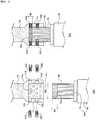
- FIG. 4(a) and (b) are diagrams sequentially illustrating a conductor connection method according to an embodiment of the present invention.
- a conductor connection method of a power cable 100 may include: fixing an adapter 80 by inserting a conductor part 10 of the power cable 100 thereinto via an open lower end of the adapter 80, the adapter 80 being formed in a cylindrical shape, an upper end and a lower end of which are open; injecting a plurality of conductive particles mp into an accommodation space 820 between an upper end of the conductor part 10 and the upper end of the adapter 80; inserting the conductor part 10 of the power cable 100, to which the adapter 80 is fixed, into an accommodation groove 71a of a conductor lead-out rod 70 via an opening 711 of a lower end of the conductor lead-out rod 70 having a plurality of fastening holes; fixing the conductor part 10 by fastening the conductor lead-out rod 70 with a fixing bolt 310; and applying an electric current to the conductor part 10 by fastening the conductor lead-out rod 70 with a conducting bolt 310 to compress the injected conductive particles mp to reduce
- the conductor part 10 of the power cable 100 is electrically connected to the conductor lead-out rod 70 by injecting additional conductive particles mp between the conductor part 10 of the power cable 100, which is to be connected and is inserted into the conductor lead rod 70, and the conductor lead-out rod 70 and fastening the conducting bolt 310 in an inward direction to reduce void between the conductive particles mp, thereby making them closely contact. It is not easy to uniformly surface-contact an end of the conductor part 10 by a method of bringing the conductor part 10 of the power cable 100 in direct contact with the conductor lead-out rod 70, thus inevitably increasing resistance. It will take a very large amount of time to perform a compression method performed after stripping an insulating layer.
- connection to the power cable 100 may be completed by fixing the adapter 80 to the upper end of the conductor part 10, injecting the conductive particles mp into the accommodation space 82 between the upper end of the conductor part 10 and the upper end of the adapter 80, inserting the conductor part 10 of the power cable 100 via an opening in a lower end of the conductor lead-out rod 70 and fixing the conductor part 10 by fastening the fixing bolt 330, and fastening the conducting bolt 310 to minimize void between the conductive particles mp and the conductive particles mp and to complete electrical connection between conductor part 10 of the power cable 100 to be connected and the conductor lead-out rod 70.
- a process of forming the conductor connection structure of the power cable 100 according to the present invention will be described below.
- the adapter 80 is fixed to the upper end of the conductor part 10 by inserting the conductor part 10 through the open lower end of the adapter 80.
- the length by which the upper end of the conductor part 10 of the power cable 100 is inserted into the adapter 80 is set to be smaller than a total length of the adapter 80. That is, as illustrated in FIG. 4(a) , the upper end of the conductor part 10 is set to be lower than the upper end of the adapter 80 when the upper end of the conductor part 10 is inserted through the lower end of the adapter 80.
- the accommodation space 82 for accommodating the conductive particles mp may be provided between the upper end of the conductor part 10 of the power cable 100 and the upper end of the adapter 80.
- the accommodation space 82 may have a first depth H1.
- a plurality of conductive particles mp may be injected into the accommodation space 82 between the upper end of the conductor part 10 and the upper end of the adapter 80.
- the conductive particles mp are injected into the accommodation space 82 through the open upper portion of the adapter 80 fixed to the upper end of the conductor part 10.
- the conductive particles mp may be injected while checking the open upper end of the adapter 80 with observation by the naked eyes and thus may be supplied to be uniformly distributed in the accommodation space 82.
- the conductive particles mp may be formed of a metal material having high electrical conductivity.
- the conductive particles mp may be formed of silver, copper or an alloy thereof or a metal material plated with silver, copper or an alloy thereof, and obtained by finely cutting metal wire.
- the conductive particles mp may be formed of various materials, such as copper, silver, a copper alloy, a silver alloy, silver-plated copper, a silver-alloy-plated copper, a silver-plated copper alloy, a silver-alloy-plated copper alloy, copper-plated silver, a copper-alloy-plated silver, a copper-plated silver alloy, or a copper-alloy-plated silver alloy.
- a plurality of conductive particles mp may be formed of materials in various combinations, provided copper or an alloy thereof or a metal material plated with silver, copper or an alloy thereof is used.
- the conductor part 10 of the power cable 200 to be connected may be inserted into the accommodation groove 71a inside the body part 71 through the opening 711 in the lower end of the body part 71.
- the conductor part 10 may be inserted until the upper end of the adapter 80 reaches the ceiling of the accommodation groove.
- the conductor part 10 may be inserted such that the accommodation space 82 may be compressed by the ceiling of the accommodation groove 71a of the body part 71. That is, when a height of the accommodation space 82 is a first height H1 while the adapter 80 is fixed as illustrated in FIG. 4A , the height of the accommodation space 82 is changed to a second height H2 after the conductor part 10 is inserted into the body part 71.
- the second height H may be less than the first height H1.
- the above-described process may be performed by further inserting the conductor part 10 by a certain length after the upper end of the adapter 80 reaches the ceiling of the accommodation groove 71a, when the conductor part 10 is inserted into the accommodation groove 71a through the lower end of the body part 71.
- volume of the accommodation space 82 after insertion of the conductor part 10 into the accommodation groove 71a is less than that of the accommodation space 82 before the insertion of the conductor part 10 into the accommodation groove 71a.
- the fixing of the conductor part 10 and the applying of the electric current to the conductor part 10 may be performed after the insertion of the conductor part 10 into the accommodation groove 71a of the body part 71.
- the fixing of the conductor part 10 to fix the body part 71 of the conductor lead-out rod 70 and the conductor part 10 may be performed by primarily fastening the fixing bolt 330 to pass through the adapter 80 so that the conductor of the conductor part 10 may be plastically deformed or penetrated.
- the fixing bolt 330 is preferably primarily fastened to the fastening hole 730 before the mainly fastening of the conducting bolt 310. This prevents the conductor part 10 from being pushed and separated from the body part 71 due to the pressure applied during the primarily fastening of the conducting bolt 310, and strengthens a state of contact between a side surface of an end of the conductor part 10 and the conductive particles mp.
- the conductive particles mp may be formed of a metal material, e.g., small metal particles or the like, and a considerable number of voids may exist between the conductive particles mp when the conductive particles mp are simply injected.
- the voids between the conductive particles mp are reduced or removed and a contact area between the conductive particles mp and a contact area between the conducive particles mp and the side surfaces of the ends of the conductor part 10 increase, thereby reducing contact resistance.
- the conductor lead-out rod 70 and the conductor part 10 are fixed by the fixing bolt 330, the conductor part 10 may not be pushed and separated from the body part 71 during the mainly fastening of the conducting bolt 310.
- the conducting bolt 310 may pass through the adapter 80 to be in direct contact with the end of the conductor part 10.
- the conducting bolt 310 may include a body portion (with a screw thread) between a lower end portion and a head portion, and a diameter of the body portion may be greater than or equal to a maximum diameter of the lower end of the conducting bolt 310.
- the shape of the conducting bolt 310 may be implemented by a method of configuring a shape of the lower end portion of the conducting bolt 310 in a hemispherical shape.
- the fixing bolt 330 when the fixing bolt 330 is primarily fastened as described above, the upper end of the conductor part 10 is spaced a certain distance from the ceiling of the accommodation space, and the conductor part 10 is fixed to the body part 71 of the conductor lead-out rod 70 in a state in which the accommodation space 82 inside the adapter 80 is filled with the conductive particles mp.
- the applying of the electric current to the conductor part 10 may be performed by fastening the body part 71 of the conductor lead-out rod 70 with the conducting bolt 310 to compress the injected conductive particles mp so as to reduce the voids therebetween while the conductor part 10 is fixed to the body part 71 of the conductor lead-out rod 70 and by electrically connecting the conductor lead-out rod 70 and the end of the conductor part 10 through the compressed conductive particles mp.
- the conducting bolt 310 to be fastened may pass through the adapter 80 to be in contact with the conductive particles mp compressed by the upper end of the conductor part 10 and the conducting bolt 310 to reduce void therein.
- the conducting bolt 310 when the conducting bolt 310 is primarily fastened, the conducting bolt 310 passes through the adapter 80 to be inserted into the accommodation groove 71a of the body part 71, so that the conductive particles mp may be pressurized and compressed and at the same time, a body part of the conducting bolt 310 may be in contact with the conductor part10 and the ceiling of the accommodation space. Therefore, the conducting bolt 310, the conductor part 10 and the conductor lead-out rod 70 may be brought into direct contact with one another to connect the compressed conductive particles mp and the ends (surfaces) of the conductor via the conducting bolt 310, thereby diversifying an electric conduction path.
- both the fixing bolt 330 and the conducting bolt 310 pass through the adapter 80 fixed to the upper end of the conductor part 10 during the fixing of the conductor part 10 to the conductor lead-out rod 70 by the fixing bolt 330 and the coupling and connecting electrically the conductor part 10 to the conductor lead-out rod 70 by the conducting bolt 310.
- the adapter 80 may be configured to have a thickness of approximately 0.5 mm to 1.0 mm to maintain the shape thereof even when the conductor part 10 is inserted. In this case, it may take a relatively large amount of work time in a process of fastening the fixing bolt 330 and the conducting bolt 310 to pass through the adapter 80. In particular, when the adapter 80 is not penetrated by the conducting bolt 310 during the fastening of the conducting bolt 310, a force for pressurizing the conductive particles mp by the conducting bolt 310 becomes weak and thus voids between the conductive particles mp may increase.
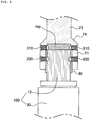
- FIG. 5 is an exploded cross-sectional view of a connection structure, for connecting a power cable and a conductor lead-out rod, according to another embodiment of the present invention to address the above problem
- FIG. 6 is an assembled cross-sectional view.
- a conductor connection device, of a power cable, for connecting a conductor part 10 consisting of a plurality of wires of a power cable 100 to a termination box, according to the present embodiment includes a conductor lead-out rod 70.
- the conductor lead-out rod 70 includes: an open lower end and provides therein an accommodation groove 71a into which an upper end of the conductor part 10 inserted into an adapter 80; a plurality of conducting fastening holes 710 formed at predetermined intervals in a circumferential direction; and fixing fastening holes 730 formed at predetermined intervals below the plurality of conducting fastening hole 710 in the circumferential direction.
- a stopper 71b may be formed on an inner circumference of the accommodation groove 71a to prevent the adapter 80 to a certain height or more during insertion of the conductor part 10 of the power cable 100.
- the accommodation groove 71a may be provided in the conductor lead-out rod 70 according to the present embodiment.
- the accommodation groove 71a may be divided into a conductor part accommodation groove 71d and a conductive particle accommodation groove 71c.
- an inner diameter R3 of the conductor part accommodation groove 71d may substantially correspond to or be greater by a certain value than an outer diameter R2 of the adapter 80. Accordingly, the conductor part 10 to which the adapter 80 is fixed is insertable into the conductor part accommodation groove 71d.
- an inner diameter of the conductive particle accommodation groove 71c may be formed to correspond to an inner diameter of the adapter 80 or an outer diameter of the conductor part 10. In this case, the adapter 80 is prevented from being inserted into the conductor particle accommodation groove 71c.
- a stopper 71b protruding toward the inside of the accommodation groove 71a may be provided between the conductor part accommodation groove 71d and the conductive particle accommodation groove 71c. That is, the conductor particle accommodation groove 71c is provided above the stopper 71b and the conductor part accommodation groove 71d is provided below the stopper 71b.
- the adapter 80 is inserted into an end of the conductor part 10, conductive particles mp are injected between an upper end of the conductor part 10 and an upper end of the adapter 80, and the conductor part 10 to which the adapter 80 is fixed is inserted into the conductor lead-out rod 70 having a configuration as described above.
- the adapter 80 is provided along an inner wall of the conductor part accommodation groove 71d, and only the conductive particles mp are accommodated in the conductive particle accommodation groove 71c.
- a first height H1 of an accommodation space on the conductor part 10 may be less than a height H3 of the conductive particle accommodation groove 71c.
- the conductive particles mp may be compressed by the upper end of the conductor part 10 and the inner wall of the conductive particle accommodation groove 71c, thereby reducing voids between the conductive particles mp.
- a plurality of conducting fastening holes 710 into which a plurality of conducting bolts 310 are to be fastened may be formed at predetermined intervals on an upper portion of the body part 71 in a circumferential direction.
- the conducting fastening holes 710 may be formed above the body part 71 to a height greater than or equal to the height of insertion of the adapter 80 or higher. That is, the conducting fastening holes 710 may be formed above the stopper 71b or formed to communicate with the conductive particle accommodation groove 71c.
- voids in the conductive particles mp may be reduced by compressing the conductive particles mp by primarily fastening the conducting bolts 310 through the conducting fastening holes 710, when the height of insertion of the adapter 80 is limited by the stopper 71b during the insertion of the conductor part 10 into the accommodation groove 71a and thus the conductive particles mp are exposed via the conductive particles accommodation groove 71c.
- a plurality of fixing fastening holes 730 to be fastened with a plurality of fixing bolts 330 may be formed at predetermined intervals under the body part 71 in the circumferential direction.
- the fastening holes 730 may be formed on the body part 71 and below the stopper 71b or formed to communicate with the conductor part accommodation groove 71d.
- connection method of a conductor connection structure according to the present embodiment will be described with reference to FIG. 7 below.
- a conductor connection method of a power cable 100 may include: fixing an adapter 80 by inserting a conductor part 10 of the power cable 100 thereinto via an open lower end of the adapter 80, the adapter 80 being formed in a cylindrical shape, an upper end and a lower end of which are open; injecting a plurality of conductive particles mp into an accommodation space 820 between an upper end of the conductor part 10 and the upper end of the adapter 80; inserting the conductor part 10 of the power cable 100, to which the adapter 80 is fixed, into an accommodation groove 71a of a conductor lead-out rod 70 via an opening 711 of a lower end of the conductor lead-out rod 70 having a plurality of fastening holes; fixing the conductor part 10 by fastening the conductor lead-out rod 70 with a fixing bolt 310; and applying an electric current to the conductor part 10 by fastening the conductor lead-out rod 70 with a conducting bolt 310 to compress the injected conductive particles mp to reduce
- the conductor part 10 is inserted through the open lower end of the adapter 80 to fix the adapter 80 to the upper end of the conductor part 10.
- the length by which the upper end of the conductor part 10 of the power cable 100 is inserted into the adapter 80 is set to be smaller than a total length of the adapter 80. That is, as illustrated in FIG. 7(a) , the upper end of the conductor part 10 is set to be lower than the upper end of the adapter 80 when the upper end of the conductor part 10 is inserted through the lower end of the adapter 80.
- an accommodation space 82 for accommodating the conductive particles mp is provided between the upper end of the conductor part 10 of the power cable 100 and the upper end of the adapter 80.
- the plurality of conductive particles mp may be injected into the receiving space 82 between the upper end of the conductor part 10 and the upper end of the adapter 80.
- the conductive particles mp are injected into the accommodation space 82 through the open upper portion of the adapter 80 fixed to the upper end of the conductor part 10.
- the conductive particles mp may be injected while checking the open upper end of the adapter 80 with eyes and thus may be supplied to be uniformly distributed in the accommodation space 82.
- the conductor part 10 of the power cable 200 to be connected may be inserted into the accommodation groove 71a inside the body part 71 through the opening 711 in the lower end of the body part 71.
- the inserting of the conductor part 10 may be performed by temporarily fastening all conducting fastening holes 710 in an upper portion of the body part 71 with the conducting bolts 310, and inserting the conductor part 10, to which the adapter 80 is fixed, into the accommodation groove 71a in the body part 71 through the opening 711 in the lower end of the body part 71.
- a height of insertion of the adapter 80 is limited during the insertion of the conductor part 10, thus causing exposure of the conductive particles mp via a conductive particle accommodation groove 71c, and thus all the plurality of conducting fastening holes 710 are temporarily fastened with the conducting bolts 310 to prevent leakage of the conductive particles mp via the conducting fastening holes 710.
- the fixing bolt 330 may be temporarily fastened into a fixing fastening hole 730 while the conductor part 10 is inserted into the body part 71. This is because when primary fastening is performed using fracture of a head portion of the fixing bolt 330, the conductor part 10 may be plastically deformed by the fixing bolt 330 and conductor wires may be introduced into the accommodation space, thus causing injection and interference of the conductive particles mp.
- the adapter 80 When the upper end of the adapter 80 passes a conductor part accommodation groove 71d and reaches a stopper 71b during the insertion of the conductor part 10, the upper end of the adapter 80 is caught by the stopper 71b, thereby limiting the height of insertion of the adapter 80.
- the conductive particles mp pass the upper end of the adapter 80 and continue to rise into a conductive particle accommodation groove 71c and thus are exposed inside the conductor particle accommodation groove 71c. Accordingly, the adapter 80 is provided along an inner wall of the conductor part accommodation groove 71d, and only the conductive particles mp are accommodated in the conductive particle accommodation groove 71c.
- a first height H1 of an accommodation space on the conductor part 10 may be less than a height H3 of the conductive particle accommodation groove 71c.
- the conductive particles mp may be compressed by the upper end of the conductor part 10 and the inner wall of the conductive particle accommodation groove 71c, thereby reducing voids between the conductive particles mp.
- the fixing of the conductor part 10 and the applying of the electric current to the conductor part 10 may be performed after the insertion of the conductor part 10 into the accommodation groove 71a of the body part 71.
- the fixing of the conductor part 10 to fix the body part 71 of the conductor lead-out rod 70 and the conductor part 10 may be performed by primarily fastening the fixing bolt 330 to pass through the adapter 80 so that the conductor of the conductor part 10 may be plastically deformed or penetrated.
- the fixing bolt 330 is preferably primarily fastened to the fastening hole 730 before the mainly fastening of the conducting bolt 310. This prevents the conductor part 10 from being pushed and separated from the body part 71 due to the pressure applied during the primarily fastening of the conducting bolt 310, and strengthens a state of contact between a side surface of an end of the conductor part 10 and the conductive particles mp.
- the conductive particles mp may be formed of a metal material, e.g., small metal particles or the like, and a considerable number of voids may exist between the conductive particles mp when the conductive particles mp are simply injected.
- the voids between the conductive particles mp are reduced or removed and a contact area between the conductive particles mp and a contact area between the conducive particles mp and the side surfaces of the ends of the conductor part 10 increase, thereby reducing contact resistance.
- the conductor lead-out rod 70 and the conductor part 10 are fixed by the fixing bolt 330, the conductor part 10 may not be pushed and separated from the body part 71 during the mainly fastening of the conducting bolt 310.
- the conducting bolt 310 may be primarily fastened in direct contact with the end of the conductor part 10.
- the conducting bolt 310 does not pass through the adapter 80 and is brought in direct contact with the conductive particles mp to compress the conductive particles mp. This is because the height of insertion of the adapter 80 is limited by the stopper 71b as described above. Therefore, the conducting bolt 310 may be easily primarily fastened unlike in the embodiment of FIG. 3 , and the conductive particles mp may be directly compressed to minimize voids therebetween.
- the conducting bolt 310 may include a body portion (with a screw thread) between a lower end portion and a head portion, and a diameter of the body portion may be greater than or equal to a maximum diameter of the lower end of the conducting bolt 310.
- the shape of the conducting bolt 310 may be implemented by a method of configuring a shape of the lower end portion of the conducting bolt 310 in a hemispherical shape.
- the fixing bolt 330 when the fixing bolt 330 is primarily fastened as described above, the upper end of the conductor part 10 is spaced a certain distance from the ceiling of the accommodation space and the conductor part 10 is fixed to the body part 71 of the conductor lead-out rod 70 in a state in which the inside of the conductive particle accommodation groove 71c is filled with the conductive particles mp.
- the applying of the electric current to the conductor part 10 may be performed by fastening the body part 71 of the conductor lead-out rod 70 with the conducting bolt 310 to compress the injected conductive particles mp so as to reduce the voids therebetween while the conductor part 10 is fixed to the body part 71 of the conductor lead-out rod 70 and by electrically connecting the conductor lead-out rod 70 and the end of the conductor part 10 through the compressed conductive particles mp.
- the conducting bolt 310 may be fastened to be in contact with the conductive particles mp which is compressed by the upper end of the conductor part 10 and the conducting bolt 310 to reduce voids therein.
- the conducting bolt 310 when the conducting bolt 310 is fastened, the conducting bolt 310 is inserted into the conductor particle accommodation groove 71c to pressurize and compress the conductive particles mp and to bring the body portion of the conducting bolt 310 into contact with the conductor part 10 and the ceiling of the accommodation space. Therefore, the conducting bolt 310, the conductor part 10 and the conductor lead-out rod 70 may be brought into direct contact with one another to connect the compressed conductive particles mp and the ends (surfaces) of the conductor via the conducting bolt 310, thereby diversifying an electric conduction path.
Landscapes
- Engineering & Computer Science (AREA)
- General Engineering & Computer Science (AREA)
- Mechanical Engineering (AREA)
- Connections Effected By Soldering, Adhesion, Or Permanent Deformation (AREA)
- Cable Accessories (AREA)
Abstract
Description
- The present invention relates to a connection structure for connecting a power cable and a power cable conductor, and a conductor connection device of a power cable. More particularly, the present invention relates to a connection structure for connecting a power cable and a conductor lead-out rod to minimize electrical resistance of a contact surface, and conductor connection device of a power cable.
- In general, a power cable is installed under or on the ground or at the sea bottom to supply power to a desired place using a conductor that supplies power. It is very important to insulate the conductor of the power cable. To this end, an insulating layer for insulating the conductor is formed of cross-linked polyethylene (XLPE) and the like or formed by rolling up insulating paper.
- Power cables are connected at intervals of several hundred meters or tens of kilometers through a joint box, and ends of the power cables are connected to overhead lines by a termination connection box.
- Examples of the joint box include a tape-type junction box (TJ), a prefabricated junction box (PJ), a pre-mold junction box (PMJ), a heterogeneous junction box, and the like. Examples of the termination connection box include an aerial termination connection box (EB-A), a gas-immersed termination connection box (EB-G), an oil-immersed termination connection box (EB-O), and the like according to a connection state of an end of a conductor taken out of a cable.
- The aerial termination connection box (EB-A) is used to connect an overhead line and an underground line in an outdoor substation. The gas-immersed termination connection box (EB-G) is generally installed in an indoor substation and used in a limited space or when the distances to other buildings are limited. The oil-immersed termination connection box (EB-O) is similar to the gas-immersed termination connection box and is used when a cable and a transformer are connected within an oil-immersed case.
- The termination connection box may include an insulator storing insulating oil, a power cable inserted into the insulating tube, and a conductor lead-out rod, one end of which is fixed to a conductor part inside the power cable and another end of which is exposed to the outside of the insulating tube.
- In the related art, in order to connect a power cable and a conductor lead-out rod of a termination connection box, insulating layers of strands of a conductor part are removed, the resultant strands are gathered, the power cable and the conductor lead-out rod of the termination connection box, which are to be connected to each other, are brought into contact with each other and are thereafter compressed.
- However, the method of connecting the power cable and the conductor lead-out rod of the termination connection box by removing the insulating layers of the strands of the conductor part and gathering and compressing the resultant strands is disadvantageous in that it takes a long time to perform the work, there are potential quality risks due to the scattering of a conductive material during the removal of the insulating layers, and considerable work proficiency is required.
- The present invention is directed to providing a connection structure for connecting a power cable and a conductor lead-out rod to minimize electrical resistance of a contact surface, and a conductor connection device of a power cable.
- To achieve these objects, the present invention provides a connection structure, for connecting a power cable and a conductor lead-out rod, which connects a conductor part including a plurality of wires of a power cable to a conductor lead-out rod of a termination connection box, the connection structure comprising: a conductor part of a power cable; an adapter configured into which the conductor part is inserted through an open lower end thereof, the adapter being formed in a cylindrical shape, an upper end and the lower end of which are open; a conductor lead-out rod providing an accommodation groove into which the conductor part of the power cable inserted into the adapter is inserted via an opening in a lower end thereof, the conductor lead-out rod including a plurality of fastening holes; a plurality of conductive particles injected into an accommodation space on an upper end of the conductor part inserted into the accommodation groove of the conductor lead-out rod to electrically connect the conductor part and the conductor lead-out rod; at least one conducting bolt configured to be fastened into the fastening hole to apply pressure to the conductive particles injected into the accommodation space so as to electrically connect the conductor part and the conductor lead-out rod; and a fixing bolt configured to be fastened into the fastening hole to fix the conductor part inserted into the accommodation groove.
- And the conducting bolt and the fixing bolt each may comprise a fracture bolt, a head portion of which is fractured and separated when a torque of a predetermined magnitude or more is applied thereto.
- And when the conducting bolt is fastened while the conductive particles are injected into the accommodation space, the conducting bolt passes through the adapter and may be brought into contact with the conductive particles compressed by an upper end of the conductor part and the conducting bolt to reduce voids therein.
- And the conductive particles may comprise silver, copper, an alloy thereof, or a metal material plated with silver, copper or the alloy thereof.
- And the conductive particles may comprise cut copper wires or silver-plated cut copper wires.
- And the conductor lead-out rod and the adapter may be each formed of tin-plated copper or a tin-plated copper alloy.
- And the fixing bolt and the conducting bolt may be each formed of brass or a brass alloy.
- And a thickness of the adapter may be in a range of 0.1 mm to 1.0 mm.
- And the conductor lead-out rod may comprise a body part providing the accommodation groove which has an opening in a lower end thereof and into which an upper end of the conductor part inserted into the adapter is inserted; and an extension extending upward from an upper end of the body part, and a plurality of conducting fastening holes into which a plurality of conducting bolts are fastened are provided in an upper portion of the body part at predetermined intervals in a circumferential direction, and a plurality of fixing fastening holes into which a plurality of fixing bolts are fastened are provided in a lower portion of the body part at predetermined intervals in the circumferential direction.
- And the conducting fastenings hole and the fixing fastening holes may be alternately formed in a direction perpendicular to the body part.
- And to achieve these objects, the present invention provides a connection structure, for connecting a power cable and a conductor lead-out rod, which connects a conductor part including a plurality of wires of a power cable to a conductor lead-out rod of a termination connection box, the connection structure comprising: a conductor part of a power cable; an adapter configured into which the conductor part is inserted through an open lower end thereof, the adapter being formed in a cylindrical shape, an upper end and the lower end of which are open; a conductor lead-out rod providing an accommodation groove into which the conductor part of the power cable inserted into the adapter is inserted into an opening in a lower end thereof, the conductor lead-out rod including: a stopper configured to prevent the adapter from being inserted above a predetermined height into the accommodation groove during the insertion of the conductor part of the power cable, the stopper being formed on an inner circumference of the accommodation groove; and a plurality of fastening holes; a plurality of conductive particles injected into an accommodation space in an upper portion of an upper end of the conductor part inserted into the accommodation groove of the conductor lead-out rod, the conductive particles being exposed via the accommodation groove during the insertion of the conductor part into the accommodation groove, thus electrically connecting the conductor part and the conductor lead-out rod; at least one conducting bolt configured to be fastened into the fastening hole to apply pressure to the conductive particles injected into the accommodation space so as to electrically connect the conductor part and the conductor lead-out rod; and a fixing bolt configured to be fastened into the fastening hole to fix the conductor part inserted into the accommodation groove.
- And the conducting bolt and the fixing bolt each may comprise a fracture bolt, a head portion of which is fractured and separated when a torque of a predetermined magnitude or more is applied thereto.
- And when the conducting bolt may be fastened while the conductive particles are injected into the accommodation space, the conducting bolt is brought into contact with the conductive particles compressed by an upper end of the conductor part and the conducting bolt to reduce voids therein.
- And the conductor lead-out rod comprises: a body part providing the accommodation groove which includes an opening at a lower end thereof and into which the upper end of the conductor part inserted into the adapter is inserted; and an extension extending upward from the upper end of the body part, and a plurality of conducting fastening holes into which a plurality of conducting bolts are fastened are formed on an upper portion of the body part at predetermined intervals in a circumferential direction, and a plurality of fixing fastening holes into which a plurality of fixing bolts are fastened are formed on a lower portion of the body part at predetermined intervals in the circumferential direction.
- And the conducting fastening hole may be formed on the upper portion of the body part at a height equal to or greater than a height of insertion of the adapter.
- And to achieve these objects, the present invention provides a conductor connection device for connecting a conductor part of a power cable to a conductor lead-out rod, the conductor connection device comprising: an adapter, an upper end and a lower end of which are open and thus into which an upper end of the conductor part is inserted through the lower end; a conductor lead-out rod providing an accommodation groove, a lower end of which is open and thus into which the conductor part inserted into the adapter is inserted, the conductor lead-out rod including: a plurality of conducting fastening holes provided at predetermined intervals in a circumferential direction; and a plurality of fixing fastening holes provided at predetermined intervals below the plurality of conducting fastening holes in the circumferential direction; at least one conducting bolt fastened into the conducting fastening hole to electrically connect the conductor part and the conductor lead-out rod; at least one fixing bolt fastened into the fixing fastening hole to fix the conductor part accommodated in the accommodation groove of the conductor lead-out rod; and a plurality of conductive particles accommodated in an accommodation space on an upper end of the conductor part inserted into the accommodation groove of the conductor lead-out rod to electrically connect the conductor part and the conductor lead-out rod.
- And to achieve these objects, the present invention provides a conductor connection device for connecting a conductor part of a power cable to a conductor lead-out rod, the conductor connection device comprising: an adapter, an upper end and a lower end of which are open and thus into which an upper end of the conductor part is inserted through the lower end; a conductor lead-out rod providing an accommodation groove, a lower end of which is open and thus into which the conductor part inserted into the adapter is inserted, the conductor lead-out rod including: a plurality of conducting fastening holes provided at predetermined intervals in a circumferential direction; and a plurality of fixing fastening holes provided at predetermined intervals below the plurality of conducting fastening holes in the circumferential direction, wherein a stopper is provided on an inner circumference of the accommodation groove to prevent the adapter from being inserted above a predetermined height during the insertion of the conductor part of the power cable; at least one conducting bolt fastened into the conducting fastening hole to electrically connect the conductor part and the conductor lead-out rod; at least one fixing bolt fastened into the fixing fastening hole to fix the conductor part accommodated in the accommodation groove of the conductor lead-out rod; and a conductive particles accommodated in an accommodation space on an upper end of the conductor part inserted into the accommodation groove of the conductor lead-out rod, the conductive particles being exposed via the accommodation groove during downward movement of the adapter, thus electrically connecting the conductor part and the conductor lead-out rod.
- And the conducting fastening hole may be formed on the upper portion of the body part at a height equal to or greater than a height of insertion of the adapter.
- And the accommodation groove may comprise : a conductive particle accommodation groove provided above the stopper to accommodate the conductive particles; and a conductor part accommodation groove which is provided below the stopper and into which the conductor part injected into the adapter is inserted.
- And the conducting fastening hole may be formed to communicate with the conductive particle accommodation groove, and the fixing fastening hole is formed to communicate with the conductor part accommodation groove.
-
-
FIG. 1 illustrates an example of a connection box. -
FIG. 2 illustrates an example of a power cable. -
FIG. 3 is an exploded perspective view of a connection structure for connecting a power cable and a conductor lead-out rod according to an embodiment of the present invention. -
FIG. 4 is a diagram sequentially illustrating a conductor connection method according to an embodiment of the present invention. -
FIG. 5 is an exploded perspective view of a connection structure for connecting a power cable and a conductor lead-out rod according to another embodiment of the present invention. -
FIG. 6 is a side cross-sectional view of a connection structure for connecting a power cable and a conductor lead-out rod according to another embodiment of the present invention. -
FIG. 7 is a diagram sequentially illustrating a conductor connection method according to another embodiment of the present invention. - Hereinafter, exemplary embodiments of the present invention will be described in detail. The present invention is, however, not limited thereto and may be embodied in many different forms. Rather, the embodiments set forth herein are provided so that this disclosure may be thorough and complete and fully convey the scope of the invention to those skilled in the art. Throughout the specification, the same reference numbers represent the same elements.
-
FIG. 1 illustrates an example of atermination connection box 1000 provided with a power cable and a conductor connection device. Hereinafter, the present invention will be described with respect to the structure of an aerial termination connection box, but a conductor connection device of power cable, a structure for connecting a power cable and a conductor lead-out rod, and a method of connecting a power cable and a conductor lead-out rod according to the present invention are applicable to various types of connection boxes such as a gas-immersed termination connection box (EB-G). - The
termination connection box 1000 ofFIG. 1 includes aninsulating tube 1 providing a space for storing insulatingoil 13, apower cable 100 fixed into the insulating tube, and a conductor lead-outrod 70, one end of which is electrically connected to thepower cable 100 and another end of which is exposed to the outside of theinsulating tube 1. - The
insulating tube 1 may be provided in various shapes for storing the insulatingoil 13. InFIG. 1 , theinsulating tube 1 may include an empty tube body having a cylindrical shape, anupper bracket 14 coupled to the tube body to form an upper surface of the tube body, and alower bracket 15 coupled to the tube body to form a lower surface of the tube body. The insulatingoil 13 electrically insulates thepower cable 100 and an inner circumferential surface of theinsulating tube 1. - The
power cable 100 is fixed into theinsulating tube 1 while passing through thelower bracket 15. That is, theinsulating tube 1 insulates and supports thepower cable 100. Accordingly, electrical insulation strength of theinsulating tube 1 should be sufficiently high. To this end, a plurality of corrugations/protrusions 11 are provided on a circumferential surface of theinsulating tube 1. The electrical insulation strength of the insulating tube may be improved by increasing an insulation distance using the corrugations/protrusions 11. Theinsulating tube 1 is preferably manufactured using hard ceramics or a polymer resin so that theinsulating tube 1 may have insulation strength and an appropriate level of strength thereof may be maintained. - The
power cable 100 is provided to pass through thelower bracket 15 and be fixed into theinsulating tube 1. An upper end of thepower cable 100 located inside the insulatingtube 1 is coupled to the conductor lead-outrod 70 formed of a conductor at the top of the insulatingtube 1. - As illustrated in
FIG. 2 , thepower cable 100 connectable using a conductor connection structure according to the present invention includes aconductor part 10, aninner semiconducting layer 20 surrounding theconductor part 10, an insulatinglayer 30 surrounding theinner semiconducting layer 20, an outersemiconducting layer 40 surrounding the insulatinglayer 30, ashielding layer 50 surrounding the outersemiconducting layer 40 and formed of a metal sheath or a neutral wire for electrical shielding and return of short-circuit current, and asheath 60 surrounding theshielding layer 50. - The
conductor part 10 may be a wire formed of copper or aluminum, and preferably, copper, or a stranded wire consisting of a plurality of such wires. Specifications of theconductor part 10, including a diameter of theconductor part 10, a diameter ofwires 11 constituting the stranded wire, etc. may vary according to a transmission voltage, usage, etc. of thepower cable 100 including theconductor part 10, and may be appropriately selected by a designer. When theconductor part 10 includes thewires 11 and each of thewires 11 is provided in an insulated state, conductor resistance decreases due to the skin effect, thereby maximizing a power transmission rate. - The
inner semiconducting layer 20 of thepower cable 100 is provided between theconductor part 10 and the insulatinglayer 30 to remove an air layer causing delamination between theconductor part 10 and the insulatinglayer 30 and to alleviate local electric field concentration. - The outer
semiconducting layer 40 allows a uniform electric field to be applied to the insulatinglayer 30, alleviates local electric field concentration, and protects the insulatinglayer 30 from the outside. - The
inner semiconducting layer 20 and the outersemiconducting layer 40 are formed by extrusion of a semiconducting composition in which conductive particles, such as carbon black, carbon nanotubes, carbon nanoplates or graphite, are dispersed in a base resin and a crosslinking agent, an antioxidant, a scorch inhibitor, or the like is additionally added. - Here, the base resin may be an olefin resin similar to a base resin of an insulating composition for forming the insulating
layer 30 for interlayer adhesion between theinner semiconducting layer 20 and the outersemiconducting layer 40 and the insulatinglayer 30. - The insulating
layer 30 may include, for example, a polyolefin resin, such as polyethylene or polypropylene, as a base resin, and may be preferably formed by extruding an insulating composition containing a polyethylene resin as a base resin. - The polyethylene resin may include ultra-low-density polyethylene (ULDPE), low-density polyethylene (LDPE), linear low-density polyethylene (LLDPE), medium-density polyethylene (MDPE), high-density polyethylene (HDPE), or the like. In the case of a high-voltage cable, existing OF cables are being quickly replaced with cross-linked polyethylene (XLPE) insulated cables.
- The
sheath 60 which is an outermost portion of thepower cable 100 may be formed of polyethylene, polyvinyl chloride, or polyurethane. - Referring back to
FIG. 1 , thepower cable 100 passes through thelower bracket 15 such that an end portion thereof is located inside the insulatingtube 1, and theconductor part 10 is exposed via an end of thepower cable 100 inside the insulatingtube 1. - That is, the end portion of the
conductor part 10 is exposed via the end of thepower cable 100 inside the insulatingtube 1 when thesheath 60, theshielding layer 50, the outersemiconducting layer 40, the insulatinglayer 30 and theinner semiconducting layer 20, which cover theconductor part 10, are removed. - The
power cable 100 except the end of thepower cable 100 may be inserted into the insulatingtube 1 in a state in which the insulatinglayer 30 and the outersemiconducting layer 40 are exposed. That is, as illustrated inFIG. 1 , thepower cable 100 may be fixed into the insulatingtube 1 in a state in which theconductor part 10, the insulatinglayer 30, and the outersemiconducting layer 40 are exposed inside the insulatingtube 1. - When the
power cable 100 from which a part of the outersemiconducting layer 40 is removed to expose the insulatinglayer 30 is inserted into the insulatingtube 1, an electric field may be concentrated at an end of the outersemiconducting layer 40 when a voltage is applied between the outersemiconducting layer 40 and theinner semiconducting layer 20. The concentration of the electric field may cause damage to the outersemiconducting layer 40 and the insulatinglayer 30. Accordingly, an electric-field mitigating cone 170 may be provided inside the insulatingtube 1 to relieve concentration of an electric field in thepower cable 100. - The electric-
field mitigating cone 170 may include asemiconducting part 173 connected to the outersemiconducting layer 40 of thepower cable 100 and aninsulating part 171 covering thesemiconducting part 173. The insulatingpart 171 provided outside the electric-field mitigating cone 170 is formed of, for example, liquid silicone rubber (LSR) and is provided outside the electric-field mitigating cone 170 to ensure insulation performance. - The conductor lead-out
rod 70 is a conductive member provided to pass through theupper bracket 14 such that a lower end thereof is coupled to an end of theconductor part 10 and an upper end thereof is exposed to the outside. - According to the related art, for connection to the wire-insulated
power cable 100 having the configuration as described above, insulating layers of wires are removed, theconductor part 10 of thepower cable 10 is inserted into the conductor lead-outrod 70, and the conductor lead-outrod 70 is compressed. In contrast, according to the present invention, as described below, theconductor part 10 and the conductor lead-outrod 70 may be electrically connected by inserting theconductor part 10 of thepower cable 100, which is to be connected, into the conductor lead-outrod 70, injecting conductive particles mp into a center of theconductor part 10, and fastening theconductor part 10 and the conductor lead-outrod 70 by a conductingbolt 310. This will be described in detail with reference to the drawings below. -
FIG. 3 is an exploded perspective view of a connection structure for connecting a power cable and a conductor lead-out rod according to an embodiment of the present invention. - First, as illustrated in
FIG. 2 , apower cable 100 connectable by the connection structure therefor according to the present invention may include aconductor part 10, aninner semiconducting layer 20 surrounding theconductor part 10, an insulatinglayer 30 surrounding theinner semiconducting layer 20, an outersemiconducting layer 40 surrounding the insulatinglayer 30, ashielding layer 50 surrounding the outersemiconducting layer 40 and formed of a metal sheath or a neutral wire for electrical shielding and return of short-circuit current, asheath 60 surrounding theshielding layer 50, and the like. - A conductor connection device, of a power cable, for connecting the conductor part 10 consisting of a plurality of strands of the power cable 100 according to the present invention to a termination connection box may include: an adapter 80, an upper end and a lower end of which are open so that an upper end portion of the conductor part 10 may be inserted via the lower end of the adapter 80; a conductor lead-out rod 70 providing an accommodation groove 71a having an open lower end into which an upper end of the conductor part 10, when inserted into the adapter 80, is inserted (see
FIG. 5 ), and including a plurality of conducting fastening holes 710 provided at predetermined intervals in a circumferential direction and a plurality of fixing fastening holes 730 provided at predetermined intervals in the circumferential direction and below the plurality of conducting fastening holes 710; at least one conducting bolt 310 each fastened into one of the conducting fastening holes 710 to electrically connect the conductor part 10 to the conductor lead-out rod 70; at least one fixing bolt 330 each fastened into one of the fixing fastening hole 730 to fix the conductor part 10 accommodated in the accommodation groove 71a of the conductor lead-out rod 70; and a plurality of conductive particles mp accommodated in an accommodation space between an upper end of the conductor part 10 and an upper end of the adapter 80 to electrically connect the conductor part 10 and the conductor lead-out rod 70. - Here, the accommodation space refers to a space of the
accommodation groove 71a excluding an area occupied by theconductor part 10 when theconductor part 10 is inserted thereinto. - Referring to
FIG. 3 , a conductor connection structure of thepower cable 100 according to the present invention may include the conductor lead-outrod 70 into which theconductor part 10 of thepower cable 100 is inserted to be electrically connected and fixed. - The
conductor part 10 of thepower cable 100 is inserted into theaccommodation groove 71a of abody part 71 while being inserted by a certain length into theadapter 80. - In this case, the length by which the upper end of the
conductor part 10 of thepower cable 100 is inserted into theadapter 80 is set to be smaller than a total length of theadapter 80. That is, as illustrated inFIG. 3 , the upper end of theconductor part 10 is set to be lower than the upper end of theadapter 80 when the upper end of theconductor part 10 is inserted through the lower end of theadapter 80. - In this case, an
accommodation space 82 for accommodating the conductive particles mp may be provided between the upper end of theconductor part 10 of thepower cable 100 and the upper end of theadapter 80. - Therefore, after inserting the
conductor part 10 into theadapter 80, the conductive particles mp may be injected into theaccommodation space 82 to fill theaccommodation space 82 with the conductive particles mp. - In this case, the conductive particles mp are injected through the open upper end of the
adapter 80 and thus the conductive particles mp may be uniformly dispersed and supplied. - In addition, because the conductive particles mp are accommodated in the upper end of the
conductor part 10 inside theadapter 80, loss of the conductive particles mp may be prevented and theconductor part 10 may be stably inserted into theaccommodation groove 71a even when theconductor part 10 is inserted into theaccommodation groove 71a of thebody part 71. - The
adapter 80 should have rigidity sufficient to provide theaccommodation space 82 for accommodating the conductive particles mp even when theconductor part 10 is inserted thereinto, and have rigidity that is within a range to be penetrated by the conductingbolt 310 when a certain torque or more is applied to the conductingbolt 310, because the conductingbolt 310 should pass through theadapter 80 to apply pressure to the conductive particles mp when the conductingbolt 310 is fastened as will be described below. - In addition, the
adapter 80 is preferably formed of a material having high electrical conductivity because it is located between a side surface of theconductor part 10 and an inner wall of theaccommodation groove 71a of the conductor lead-outrod 70 in the conductor connection structure according to the present invention. - Thus, the
adapter 80 may be formed of a copper material having a thickness of approximately 0.5 mm to 1.0 mm. - Because the
conductor part 10 is inserted into theadapter 80, an inner diameter R1 of theadapter 80 may approximately correspond to or be greater by a certain value than an outer diameter of theconductor part 10. In addition, because theadapter 80 is inserted into theaccommodation groove 71a of thebody part 71, an outer diameter R2 of theadapter 80 may approximately correspond to or be less by an inner diameter R3 of theaccommodation groove 71a of the body part 71 (seeFIG. 4 ) . - The conductor lead-out
rod 70 may provide theaccommodation groove 71a into which theconductor part 10 of thepower cable 100 inserted into theadapter 80 is inserted through anopening 711 in a lower end thereof, and include a plurality offastening holes - For example, as illustrated in
FIG. 3 , the conductor lead-outrod 70 may include thebody part 71 providing theaccommodation groove 71a which has theopening 711 in the lower end and into which an upper end of theconductor part 10 is inserted, and anextension 73 extending upward from an upper end of thebody part 71. - The
accommodation groove 71a may be provided in thebody part 71, into which theconductor part 10 is inserted via theopening 711 in the lower end of theconductor part 10, and theextension 73 extending upward from thebody part 71 may be exposed to the outside via an upper portion of the termination connection box as described above and connected to an overhead line. - In this case, a diameter of the
extension 73 may be less than that of thebody part 71, and aninclined connection part 74 may be provided between thebody part 71 and theextension 73 in this case. - That is, the
extension 73 is coupled to thebody part 71 through theinclined connection part 74, and an outer diameter from theextension 73 toward thebody part 71 increases through theinclined connection part 74. - In this case, the conductor lead-out
rod 70 may be formed of a metal material having high electrical conductivity, and for example, the conductor lead-outrod 70 may be made of tin-plated copper or tin-plated copper alloy material. - In addition, the
body part 71 of the conductor lead-outrod 70 may be provided with fastening holes to be fastened with a plurality of bolts. - Specifically, a plurality of
fastening holes 710 into which a plurality of conductingbolts 310 are fastened may be formed at predetermined intervals on the upper portion of thebody part 71 along the circumferential direction. - Among the plurality of fastening holes formed in the
body part 71, a fastening hole formed in upper portion of thebody part 71 is the conductingfastening hole 710 to be fastened with the conductingbolt 310 for electrically connecting theconductor part 10 and the conductor lead-outrod 70 by applying pressure to the conductive particles mp injected into an accommodation space between theconductor part 10 and the ceiling ofaccommodation groove 71a in a state in which theconductor part 10 of thepower cable 100 to be connected is inserted into theaccommodation groove 71a of thebody part 71. - Similarly, a plurality of fixing
fastening holes 730 to be fastened with a plurality of fixingbolts 330 may be formed at predetermined intervals below thebody part 71 in a circumferential direction. - Among the plurality of fastening holes formed in the
body part 71, a fastening hole formed in a lower portion of thebody part 71, i.e., below the conductingfastening hole 710, is the fixingfastening hole 730 to be fastened with the fixingbolt 330 to connect and fix theconductor part 10 and the conductor lead-outrod 70 in a state in which theconductor part 10 of thepower cable 100 to be connected is inserted into thebody part 71. - When the fixing
bolt 330 is fastened into the fixingfastening hole 730, a portion of theconductor part 10 to be fastened may be plastically deformed or penetrated, thereby preventing movement of theconductor part 10 in a lengthwise direction of the conductor lead-outrod 70 or in a vertical direction ofFIG. 3 . - The conducting
fastening hole 10 fastened with the conductingbolt 310 ofFIG. 3 may be formed at a position corresponding to the accommodation space, for accommodation of the conductive particles mp, of the upper portion of thebody part 71. Therefore, a plurality of conducting fastening holes 210 may be formed at predetermined intervals along the circumference of the upper portion of thebody part 71. - Similarly, the fixing
fastening holes 730 may be formed at predetermined intervals in a lower region of thebody part 71, i.e., below the conductingfastening holes 710, along the circumferences of positions spaced the same distance from each other in the lengthwise direction of thebody part 71. - In this case, as illustrated in
FIG. 3 , adjacent fastening holes may be alternately formed in the longitudinal direction of thebody part 71 or in a direction perpendicular to thebody portion 71. This is to disperse an effect of fixing the fixingbolt 330 to theentire conductor part 10 and prevent an effect of compressing the conductive particles mp using the conductingbolt 310 from being concentrated in a specific region. - The conducting
bolt 310 may include a head portion to which torque is applied using a tool, and a threaded body portion. The head portion is a region which is fractured when fastening is completed, and the body portion is configured to be inserted and fastened into thebody part 71 when fastening is completed. - Specifically, the conducting
bolt 310 includes the head portion fractured and separated when a torque of a predetermined magnitude or more is applied thereto, the threaded body portion below the head portion, and the lower end portion below the body portion. - Each fastening hole configured to be fastened with a bolt may be provided with a screw thread to adjust a fastening force according to a depth of fastening of the conducting
bolt 310 and the fixingbolt 330. As described later, the conductingbolt 310 and the fixingbolt 330 may be configured as fracture bolts, the head portions of which are broken when a force of a predetermined magnitude or more is applied. - The conducting
bolt 310 and the fixingbolt 330 are configured as fracture bolts, because a connection structure for thepower cable 100 according to the present invention should be accommodated in a termination connection box, insulating oil or the like is stored outside the connection part, and the heads of bolts and the like should not protrude from a surface of the conductor lead-outrod 70 connected to an end of thepower cable 100 so as to prevent electric field concentration. - In this case, the fixing
bolt 330 and the conductingbolt 310 may be formed of brass or a brass alloy material. - A conductor connection method using the conductor connection structure having the above-described structure will be described with reference to the drawings below.
-
FIG. 4(a) and (b) are diagrams sequentially illustrating a conductor connection method according to an embodiment of the present invention. - A conductor connection method of a
power cable 100 according to an embodiment of the present invention may include: fixing anadapter 80 by inserting aconductor part 10 of thepower cable 100 thereinto via an open lower end of theadapter 80, theadapter 80 being formed in a cylindrical shape, an upper end and a lower end of which are open; injecting a plurality of conductive particles mp into an accommodation space 820 between an upper end of theconductor part 10 and the upper end of theadapter 80; inserting theconductor part 10 of thepower cable 100, to which theadapter 80 is fixed, into anaccommodation groove 71a of a conductor lead-outrod 70 via anopening 711 of a lower end of the conductor lead-outrod 70 having a plurality of fastening holes; fixing theconductor part 10 by fastening the conductor lead-outrod 70 with a fixingbolt 310; and applying an electric current to theconductor part 10 by fastening the conductor lead-outrod 70 with a conductingbolt 310 to compress the injected conductive particles mp to reduce voids therein and electrically connecting theconductor part 10 and the conductor lead-outrod 70 through the compressed conductive particles mp. - In the conductor connection structure of the
power cable 100 according to the present invention, theconductor part 10 of thepower cable 100 is electrically connected to the conductor lead-outrod 70 by injecting additional conductive particles mp between theconductor part 10 of thepower cable 100, which is to be connected and is inserted into theconductor lead rod 70, and the conductor lead-outrod 70 and fastening the conductingbolt 310 in an inward direction to reduce void between the conductive particles mp, thereby making them closely contact. It is not easy to uniformly surface-contact an end of theconductor part 10 by a method of bringing theconductor part 10 of thepower cable 100 in direct contact with the conductor lead-outrod 70, thus inevitably increasing resistance. It will take a very large amount of time to perform a compression method performed after stripping an insulating layer. - However, in the conductor connection structure of the
power cable 100 according to the present invention, connection to thepower cable 100 may be completed by fixing theadapter 80 to the upper end of theconductor part 10, injecting the conductive particles mp into theaccommodation space 82 between the upper end of theconductor part 10 and the upper end of theadapter 80, inserting theconductor part 10 of thepower cable 100 via an opening in a lower end of the conductor lead-outrod 70 and fixing theconductor part 10 by fastening the fixingbolt 330, and fastening the conductingbolt 310 to minimize void between the conductive particles mp and the conductive particles mp and to complete electrical connection betweenconductor part 10 of thepower cable 100 to be connected and the conductor lead-outrod 70. A process of forming the conductor connection structure of thepower cable 100 according to the present invention will be described below. - First, as illustrated in
FIG. 4(a) , theadapter 80 is fixed to the upper end of theconductor part 10 by inserting theconductor part 10 through the open lower end of theadapter 80. - In this case, the length by which the upper end of the
conductor part 10 of thepower cable 100 is inserted into theadapter 80 is set to be smaller than a total length of theadapter 80. That is, as illustrated inFIG. 4(a) , the upper end of theconductor part 10 is set to be lower than the upper end of theadapter 80 when the upper end of theconductor part 10 is inserted through the lower end of theadapter 80. - In this case, the
accommodation space 82 for accommodating the conductive particles mp may be provided between the upper end of theconductor part 10 of thepower cable 100 and the upper end of theadapter 80. Theaccommodation space 82 may have a first depth H1. - Thereafter, a plurality of conductive particles mp may be injected into the
accommodation space 82 between the upper end of theconductor part 10 and the upper end of theadapter 80. - In this case, the conductive particles mp are injected into the
accommodation space 82 through the open upper portion of theadapter 80 fixed to the upper end of theconductor part 10. - Therefore, the conductive particles mp may be injected while checking the open upper end of the
adapter 80 with observation by the naked eyes and thus may be supplied to be uniformly distributed in theaccommodation space 82. - The conductive particles mp may be formed of a metal material having high electrical conductivity. For example, the conductive particles mp may be formed of silver, copper or an alloy thereof or a metal material plated with silver, copper or an alloy thereof, and obtained by finely cutting metal wire.
- Accordingly, the conductive particles mp may be formed of various materials, such as copper, silver, a copper alloy, a silver alloy, silver-plated copper, a silver-alloy-plated copper, a silver-plated copper alloy, a silver-alloy-plated copper alloy, copper-plated silver, a copper-alloy-plated silver, a copper-plated silver alloy, or a copper-alloy-plated silver alloy. In addition, a plurality of conductive particles mp may be formed of materials in various combinations, provided copper or an alloy thereof or a metal material plated with silver, copper or an alloy thereof is used.
- After injecting the conductive particles mp, the
conductor part 10 of the power cable 200 to be connected may be inserted into theaccommodation groove 71a inside thebody part 71 through theopening 711 in the lower end of thebody part 71. - In this case, there is no need to fasten the plurality of conducting
fastening holes 710 formed in the upper portion of thebody part 71 by the conductingbolts 310. This is because the conductive particles mp are accommodated inside theadapter 80 and thus are not likely to leak even when the conductingfastening holes 710 are open. - The
conductor part 10 may be inserted until the upper end of theadapter 80 reaches the ceiling of the accommodation groove. - Alternatively, the
conductor part 10 may be inserted such that theaccommodation space 82 may be compressed by the ceiling of theaccommodation groove 71a of thebody part 71. That is, when a height of theaccommodation space 82 is a first height H1 while theadapter 80 is fixed as illustrated inFIG. 4A , the height of theaccommodation space 82 is changed to a second height H2 after theconductor part 10 is inserted into thebody part 71. The second height H may be less than the first height H1. - The above-described process may be performed by further inserting the
conductor part 10 by a certain length after the upper end of theadapter 80 reaches the ceiling of theaccommodation groove 71a, when theconductor part 10 is inserted into theaccommodation groove 71a through the lower end of thebody part 71. - In this case, volume of the
accommodation space 82 after insertion of theconductor part 10 into theaccommodation groove 71a is less than that of theaccommodation space 82 before the insertion of theconductor part 10 into theaccommodation groove 71a. - Therefore, when the
conductor part 10 is inserted into theaccommodation groove 71a of thebody part 71, pressure may be applied to the conductive particles mp accommodated in theaccommodation groove 71a to reduce voids in the conductive particles mp. - As illustrated in
FIG. 4B , the fixing of theconductor part 10 and the applying of the electric current to theconductor part 10 may be performed after the insertion of theconductor part 10 into theaccommodation groove 71a of thebody part 71. - The fixing of the
conductor part 10 to fix thebody part 71 of the conductor lead-outrod 70 and theconductor part 10 may be performed by primarily fastening the fixingbolt 330 to pass through theadapter 80 so that the conductor of theconductor part 10 may be plastically deformed or penetrated. - That is, the fixing
bolt 330 is preferably primarily fastened to thefastening hole 730 before the mainly fastening of the conductingbolt 310. This prevents theconductor part 10 from being pushed and separated from thebody part 71 due to the pressure applied during the primarily fastening of the conductingbolt 310, and strengthens a state of contact between a side surface of an end of theconductor part 10 and the conductive particles mp. - The conductive particles mp may be formed of a metal material, e.g., small metal particles or the like, and a considerable number of voids may exist between the conductive particles mp when the conductive particles mp are simply injected. However, as illustrated in
FIG. 4B , when the fastening of the conductingbolt 310 is completed while the fastening of the fixingbolt 330 is completed, the voids between the conductive particles mp are reduced or removed and a contact area between the conductive particles mp and a contact area between the conducive particles mp and the side surfaces of the ends of theconductor part 10 increase, thereby reducing contact resistance. In this case, because the conductor lead-outrod 70 and theconductor part 10 are fixed by the fixingbolt 330, theconductor part 10 may not be pushed and separated from thebody part 71 during the mainly fastening of the conductingbolt 310. - In addition, it is preferable that when the conducting
bolt 310 is primarily fastened, the conductingbolt 310 pass through theadapter 80 to be in direct contact with the end of theconductor part 10. Specifically, the conductingbolt 310 may include a body portion (with a screw thread) between a lower end portion and a head portion, and a diameter of the body portion may be greater than or equal to a maximum diameter of the lower end of the conductingbolt 310. The shape of the conductingbolt 310 may be implemented by a method of configuring a shape of the lower end portion of the conductingbolt 310 in a hemispherical shape. - As described above, when the fixing
bolt 330 is primarily fastened as described above, the upper end of theconductor part 10 is spaced a certain distance from the ceiling of the accommodation space, and theconductor part 10 is fixed to thebody part 71 of the conductor lead-outrod 70 in a state in which theaccommodation space 82 inside theadapter 80 is filled with the conductive particles mp. - The applying of the electric current to the
conductor part 10 may be performed by fastening thebody part 71 of the conductor lead-outrod 70 with the conductingbolt 310 to compress the injected conductive particles mp so as to reduce the voids therebetween while theconductor part 10 is fixed to thebody part 71 of the conductor lead-outrod 70 and by electrically connecting the conductor lead-outrod 70 and the end of theconductor part 10 through the compressed conductive particles mp. - In the applying of the electric current to the
conductor part 10, the conductingbolt 310 to be fastened may pass through theadapter 80 to be in contact with the conductive particles mp compressed by the upper end of theconductor part 10 and the conductingbolt 310 to reduce void therein. - Specifically, when the conducting
bolt 310 is primarily fastened, the conductingbolt 310 passes through theadapter 80 to be inserted into theaccommodation groove 71a of thebody part 71, so that the conductive particles mp may be pressurized and compressed and at the same time, a body part of the conductingbolt 310 may be in contact with the conductor part10 and the ceiling of the accommodation space. Therefore, the conductingbolt 310, theconductor part 10 and the conductor lead-outrod 70 may be brought into direct contact with one another to connect the compressed conductive particles mp and the ends (surfaces) of the conductor via the conductingbolt 310, thereby diversifying an electric conduction path. - In the above-described embodiment, both the fixing
bolt 330 and the conductingbolt 310 pass through theadapter 80 fixed to the upper end of theconductor part 10 during the fixing of theconductor part 10 to the conductor lead-outrod 70 by the fixingbolt 330 and the coupling and connecting electrically theconductor part 10 to the conductor lead-outrod 70 by the conductingbolt 310. - In this case, the
adapter 80 may be configured to have a thickness of approximately 0.5 mm to 1.0 mm to maintain the shape thereof even when theconductor part 10 is inserted. In this case, it may take a relatively large amount of work time in a process of fastening the fixingbolt 330 and the conductingbolt 310 to pass through theadapter 80. In particular, when theadapter 80 is not penetrated by the conductingbolt 310 during the fastening of the conductingbolt 310, a force for pressurizing the conductive particles mp by the conductingbolt 310 becomes weak and thus voids between the conductive particles mp may increase. -
FIG. 5 is an exploded cross-sectional view of a connection structure, for connecting a power cable and a conductor lead-out rod, according to another embodiment of the present invention to address the above problem, andFIG. 6 is an assembled cross-sectional view. The following embodiments will be described focusing on the differences from the previous embodiments, in which the same reference numerals are assigned to components that are the same as those in the previous embodiments. - Referring to
FIGS. 5 and6 , a conductor connection device, of a power cable, for connecting aconductor part 10 consisting of a plurality of wires of apower cable 100 to a termination box, according to the present embodiment includes a conductor lead-outrod 70. - The conductor lead-out
rod 70 according to the present embodiment includes: an open lower end and provides therein anaccommodation groove 71a into which an upper end of theconductor part 10 inserted into anadapter 80; a plurality of conductingfastening holes 710 formed at predetermined intervals in a circumferential direction; and fixingfastening holes 730 formed at predetermined intervals below the plurality of conductingfastening hole 710 in the circumferential direction. Astopper 71b may be formed on an inner circumference of theaccommodation groove 71a to prevent theadapter 80 to a certain height or more during insertion of theconductor part 10 of thepower cable 100. - That is, the
accommodation groove 71a may be provided in the conductor lead-outrod 70 according to the present embodiment. Theaccommodation groove 71a may be divided into a conductorpart accommodation groove 71d and a conductiveparticle accommodation groove 71c. - In this case, an inner diameter R3 of the conductor
part accommodation groove 71d may substantially correspond to or be greater by a certain value than an outer diameter R2 of theadapter 80. Accordingly, theconductor part 10 to which theadapter 80 is fixed is insertable into the conductorpart accommodation groove 71d. - In addition, an inner diameter of the conductive
particle accommodation groove 71c may be formed to correspond to an inner diameter of theadapter 80 or an outer diameter of theconductor part 10. In this case, theadapter 80 is prevented from being inserted into the conductorparticle accommodation groove 71c. - Accordingly, a
stopper 71b protruding toward the inside of theaccommodation groove 71a may be provided between the conductorpart accommodation groove 71d and the conductiveparticle accommodation groove 71c. That is, the conductorparticle accommodation groove 71c is provided above thestopper 71b and the conductorpart accommodation groove 71d is provided below thestopper 71b. - A process of inserting the
conductor part 10 will now be described. Theadapter 80 is inserted into an end of theconductor part 10, conductive particles mp are injected between an upper end of theconductor part 10 and an upper end of theadapter 80, and theconductor part 10 to which theadapter 80 is fixed is inserted into the conductor lead-outrod 70 having a configuration as described above. - In this case, when the upper end of the
adapter 80 passes the conductorpart accommodation groove 71d and reaches thestopper 71b, the upper end of theadapter 80 is caught by thestopper 71b and thus a height of insertion of theadapter 80 is limited. In contrast, the conductive particles mp pass the upper end of theadapter 80 and rise into the conductiveparticle accommodation groove 71c and thus are exposed inside the conductorparticle accommodation groove 71c. - Accordingly, the
adapter 80 is provided along an inner wall of the conductorpart accommodation groove 71d, and only the conductive particles mp are accommodated in the conductiveparticle accommodation groove 71c. - When the upper end of the
conductor part 10 is inserted through a lower end of theadapter 80, a first height H1 of an accommodation space on theconductor part 10 may be less than a height H3 of the conductiveparticle accommodation groove 71c. - Accordingly, when the
conductor part 10 is inserted and the height of insertion of theadapter 80 is limited by thestopper 71b, thus exposing the conductive particles mp via the conductiveparticle accommodation groove 71c, the conductive particles mp may be compressed by the upper end of theconductor part 10 and the inner wall of the conductiveparticle accommodation groove 71c, thereby reducing voids between the conductive particles mp. - A plurality of conducting
fastening holes 710 into which a plurality of conductingbolts 310 are to be fastened may be formed at predetermined intervals on an upper portion of thebody part 71 in a circumferential direction. In the present embodiment, the conductingfastening holes 710 may be formed above thebody part 71 to a height greater than or equal to the height of insertion of theadapter 80 or higher. That is, the conductingfastening holes 710 may be formed above thestopper 71b or formed to communicate with the conductiveparticle accommodation groove 71c. - Therefore, voids in the conductive particles mp may be reduced by compressing the conductive particles mp by primarily fastening the conducting
bolts 310 through the conductingfastening holes 710, when the height of insertion of theadapter 80 is limited by thestopper 71b during the insertion of theconductor part 10 into theaccommodation groove 71a and thus the conductive particles mp are exposed via the conductiveparticles accommodation groove 71c. - Similarly, a plurality of fixing
fastening holes 730 to be fastened with a plurality of fixingbolts 330 may be formed at predetermined intervals under thebody part 71 in the circumferential direction. In this case, the fastening holes 730 may be formed on thebody part 71 and below thestopper 71b or formed to communicate with the conductorpart accommodation groove 71d. - A connection method of a conductor connection structure according to the present embodiment will be described with reference to
FIG. 7 below. - A conductor connection method of a
power cable 100 according to an embodiment of the present invention may include: fixing anadapter 80 by inserting aconductor part 10 of thepower cable 100 thereinto via an open lower end of theadapter 80, theadapter 80 being formed in a cylindrical shape, an upper end and a lower end of which are open; injecting a plurality of conductive particles mp into an accommodation space 820 between an upper end of theconductor part 10 and the upper end of theadapter 80; inserting theconductor part 10 of thepower cable 100, to which theadapter 80 is fixed, into anaccommodation groove 71a of a conductor lead-outrod 70 via anopening 711 of a lower end of the conductor lead-outrod 70 having a plurality of fastening holes; fixing theconductor part 10 by fastening the conductor lead-outrod 70 with a fixingbolt 310; and applying an electric current to theconductor part 10 by fastening the conductor lead-outrod 70 with a conductingbolt 310 to compress the injected conductive particles mp to reduce voids therein and electrically connecting theconductor part 10 and the conductor lead-outrod 70 through the compressed conductive particles mp. - First, as illustrated in
FIG. 7(a) , theconductor part 10 is inserted through the open lower end of theadapter 80 to fix theadapter 80 to the upper end of theconductor part 10. - In this case, the length by which the upper end of the
conductor part 10 of thepower cable 100 is inserted into theadapter 80 is set to be smaller than a total length of theadapter 80. That is, as illustrated inFIG. 7(a) , the upper end of theconductor part 10 is set to be lower than the upper end of theadapter 80 when the upper end of theconductor part 10 is inserted through the lower end of theadapter 80. - In this case, an
accommodation space 82 for accommodating the conductive particles mp is provided between the upper end of theconductor part 10 of thepower cable 100 and the upper end of theadapter 80. - Next, as illustrated in
FIG. 7(b) , the plurality of conductive particles mp may be injected into the receivingspace 82 between the upper end of theconductor part 10 and the upper end of theadapter 80. - In this case, the conductive particles mp are injected into the
accommodation space 82 through the open upper portion of theadapter 80 fixed to the upper end of theconductor part 10. - Therefore, the conductive particles mp may be injected while checking the open upper end of the
adapter 80 with eyes and thus may be supplied to be uniformly distributed in theaccommodation space 82. - After injecting the conductive particles mp, the
conductor part 10 of the power cable 200 to be connected may be inserted into theaccommodation groove 71a inside thebody part 71 through theopening 711 in the lower end of thebody part 71. - In this case, the inserting of the
conductor part 10 may be performed by temporarily fastening all conductingfastening holes 710 in an upper portion of thebody part 71 with the conductingbolts 310, and inserting theconductor part 10, to which theadapter 80 is fixed, into theaccommodation groove 71a in thebody part 71 through theopening 711 in the lower end of thebody part 71. - Unlike the embodiment described above with reference to
FIG. 3 , in the present embodiment, a height of insertion of theadapter 80 is limited during the insertion of theconductor part 10, thus causing exposure of the conductive particles mp via a conductiveparticle accommodation groove 71c, and thus all the plurality of conductingfastening holes 710 are temporarily fastened with the conductingbolts 310 to prevent leakage of the conductive particles mp via the conducting fastening holes 710. - Although not shown in the drawings, the fixing
bolt 330 may be temporarily fastened into a fixingfastening hole 730 while theconductor part 10 is inserted into thebody part 71. This is because when primary fastening is performed using fracture of a head portion of the fixingbolt 330, theconductor part 10 may be plastically deformed by the fixingbolt 330 and conductor wires may be introduced into the accommodation space, thus causing injection and interference of the conductive particles mp. - When the upper end of the
adapter 80 passes a conductorpart accommodation groove 71d and reaches astopper 71b during the insertion of theconductor part 10, the upper end of theadapter 80 is caught by thestopper 71b, thereby limiting the height of insertion of theadapter 80. In contrast, the conductive particles mp pass the upper end of theadapter 80 and continue to rise into a conductiveparticle accommodation groove 71c and thus are exposed inside the conductorparticle accommodation groove 71c. Accordingly, theadapter 80 is provided along an inner wall of the conductorpart accommodation groove 71d, and only the conductive particles mp are accommodated in the conductiveparticle accommodation groove 71c. - When the upper end of the
conductor part 10 is inserted through the lower end of theadapter 80, a first height H1 of an accommodation space on theconductor part 10 may be less than a height H3 of the conductiveparticle accommodation groove 71c. - Accordingly, when the
conductor part 10 is inserted and the height of insertion of theadapter 80 is limited by thestopper 71b, thus exposing the conductive particles mp via the conductiveparticle accommodation groove 71c, the conductive particles mp may be compressed by the upper end of theconductor part 10 and the inner wall of the conductiveparticle accommodation groove 71c, thereby reducing voids between the conductive particles mp. - As illustrated in
FIG. 7(c) , the fixing of theconductor part 10 and the applying of the electric current to theconductor part 10 may be performed after the insertion of theconductor part 10 into theaccommodation groove 71a of thebody part 71. - The fixing of the
conductor part 10 to fix thebody part 71 of the conductor lead-outrod 70 and theconductor part 10 may be performed by primarily fastening the fixingbolt 330 to pass through theadapter 80 so that the conductor of theconductor part 10 may be plastically deformed or penetrated. - That is, the fixing
bolt 330 is preferably primarily fastened to thefastening hole 730 before the mainly fastening of the conductingbolt 310. This prevents theconductor part 10 from being pushed and separated from thebody part 71 due to the pressure applied during the primarily fastening of the conductingbolt 310, and strengthens a state of contact between a side surface of an end of theconductor part 10 and the conductive particles mp. - The conductive particles mp may be formed of a metal material, e.g., small metal particles or the like, and a considerable number of voids may exist between the conductive particles mp when the conductive particles mp are simply injected. However, as illustrated in
FIG. 7(c) , when the fastening of the conductingbolt 310 is completed while the fastening of the fixingbolt 330 is completed, the voids between the conductive particles mp are reduced or removed and a contact area between the conductive particles mp and a contact area between the conducive particles mp and the side surfaces of the ends of theconductor part 10 increase, thereby reducing contact resistance. In this case, because the conductor lead-outrod 70 and theconductor part 10 are fixed by the fixingbolt 330, theconductor part 10 may not be pushed and separated from thebody part 71 during the mainly fastening of the conductingbolt 310. - The conducting
bolt 310 may be primarily fastened in direct contact with the end of theconductor part 10. In the present embodiment, unlike the embodiment ofFIG. 3 , the conductingbolt 310 does not pass through theadapter 80 and is brought in direct contact with the conductive particles mp to compress the conductive particles mp. This is because the height of insertion of theadapter 80 is limited by thestopper 71b as described above. Therefore, the conductingbolt 310 may be easily primarily fastened unlike in the embodiment ofFIG. 3 , and the conductive particles mp may be directly compressed to minimize voids therebetween. - Specifically, the conducting
bolt 310 may include a body portion (with a screw thread) between a lower end portion and a head portion, and a diameter of the body portion may be greater than or equal to a maximum diameter of the lower end of the conductingbolt 310. The shape of the conductingbolt 310 may be implemented by a method of configuring a shape of the lower end portion of the conductingbolt 310 in a hemispherical shape. - As described above, when the fixing
bolt 330 is primarily fastened as described above, the upper end of theconductor part 10 is spaced a certain distance from the ceiling of the accommodation space and theconductor part 10 is fixed to thebody part 71 of the conductor lead-outrod 70 in a state in which the inside of the conductiveparticle accommodation groove 71c is filled with the conductive particles mp. - The applying of the electric current to the
conductor part 10 may be performed by fastening thebody part 71 of the conductor lead-outrod 70 with the conductingbolt 310 to compress the injected conductive particles mp so as to reduce the voids therebetween while theconductor part 10 is fixed to thebody part 71 of the conductor lead-outrod 70 and by electrically connecting the conductor lead-outrod 70 and the end of theconductor part 10 through the compressed conductive particles mp. - In the applying of the electric current to the
conductor part 10, the conductingbolt 310 may be fastened to be in contact with the conductive particles mp which is compressed by the upper end of theconductor part 10 and the conductingbolt 310 to reduce voids therein. - Specifically, when the conducting
bolt 310 is fastened, the conductingbolt 310 is inserted into the conductorparticle accommodation groove 71c to pressurize and compress the conductive particles mp and to bring the body portion of the conductingbolt 310 into contact with theconductor part 10 and the ceiling of the accommodation space. Therefore, the conductingbolt 310, theconductor part 10 and the conductor lead-outrod 70 may be brought into direct contact with one another to connect the compressed conductive particles mp and the ends (surfaces) of the conductor via the conductingbolt 310, thereby diversifying an electric conduction path. - While the present invention has been described above with respect to exemplary embodiments thereof, it would be understood by those of ordinary skilled in the art that various changes and modifications may be made without departing from the technical conception and scope of the present invention defined in the following claims. Thus, it is clear that all modifications are included in the technical scope of the present invention as long as they include the components as claimed in the claims of the present invention.
Claims (20)
- A connection structure, for connecting a power cable and a conductor lead-out rod, which connects a conductor part including a plurality of wires of a power cable to a conductor lead-out rod of a termination connection box, the connection structure comprising:a conductor part of a power cable;an adapter configured into which the conductor part is inserted through an open lower end thereof, the adapter being formed in a cylindrical shape, an upper end and the lower end of which are open;a conductor lead-out rod providing an accommodation groove into which the conductor part of the power cable inserted into the adapter is inserted via an opening in a lower end thereof, the conductor lead-out rod including a plurality of fastening holes;a plurality of conductive particles injected into an accommodation space on an upper end of the conductor part inserted into the accommodation groove of the conductor lead-out rod to electrically connect the conductor part and the conductor lead-out rod;at least one conducting bolt configured to be fastened into the fastening hole to apply pressure to the conductive particles injected into the accommodation space so as to electrically connect the conductor part and the conductor lead-out rod; anda fixing bolt configured to be fastened into the fastening hole to fix the conductor part inserted into the accommodation groove.
- The connection structure of claim 1, wherein the conducting bolt and the fixing bolt each comprise a fracture bolt, a head portion of which is fractured and separated when a torque of a predetermined magnitude or more is applied thereto.
- The connection structure of claim 1, wherein, when the conducting bolt is fastened while the conductive particles are injected into the accommodation space, the conducting bolt passes through the adapter and is brought into contact with the conductive particles compressed by an upper end of the conductor part and the conducting bolt to reduce voids therein.
- The connection structure of claim 1, wherein the conductive particles comprise silver, copper, an alloy thereof, or a metal material plated with silver, copper or the alloy thereof.
- The connection structure of claim 4, wherein the conductive particles comprise cut copper wires or silver-plated cut copper wires.
- The connection structure of claim 1, wherein the conductor lead-out rod and the adapter are each formed of tin-plated copper or a tin-plated copper alloy.
- The connection structure of claim 1, wherein the fixing bolt and the conducting bolt are each formed of brass or a brass alloy.
- The connection structure of claim 1, wherein a thickness of the adapter is in a range of 0.1 mm to 1.0 mm.
- The connection structure of claim 1, wherein the conductor lead-out rod comprises:a body part providing the accommodation groove which has an opening in a lower end thereof and into which an upper end of the conductor part inserted into the adapter is inserted; andan extension extending upward from an upper end of the body part, anda plurality of conducting fastening holes into which a plurality of conducting bolts are fastened are provided in an upper portion of the body part at predetermined intervals in a circumferential direction, and a plurality of fixing fastening holes into which a plurality of fixing bolts are fastened are provided in a lower portion of the body part at predetermined intervals in the circumferential direction.
- The connection structure of claim 9, wherein the conducting fastenings hole and the fixing fastening holes are alternately formed in a direction perpendicular to the body part.
- A connection structure, for connecting a power cable and a conductor lead-out rod, which connects a conductor part including a plurality of wires of a power cable to a conductor lead-out rod of a termination connection box, the connection structure comprising:a conductor part of a power cable;an adapter configured into which the conductor part is inserted through an open lower end thereof, the adapter being formed in a cylindrical shape, an upper end and the lower end of which are open;a conductor lead-out rod providing an accommodation groove into which the conductor part of the power cable inserted into the adapter is inserted into an opening in a lower end thereof, the conductor lead-out rod including: a stopper configured to prevent the adapter from being inserted above a predetermined height into the accommodation groove during the insertion of the conductor part of the power cable, the stopper being formed on an inner circumference of the accommodation groove; and a plurality of fastening holes;a plurality of conductive particles injected into an accommodation space in an upper portion of an upper end of the conductor part inserted into the accommodation groove of the conductor lead-out rod, the conductive particles being exposed via the accommodation groove during the insertion of the conductor part into the accommodation groove, thus electrically connecting the conductor part and the conductor lead-out rod;at least one conducting bolt configured to be fastened into the fastening hole to apply pressure to the conductive particles injected into the accommodation space so as to electrically connect the conductor part and the conductor lead-out rod; anda fixing bolt configured to be fastened into the fastening hole to fix the conductor part inserted into the accommodation groove.
- The connection structure of claim 11, wherein the conducting bolt and the fixing bolt each comprise a fracture bolt, a head portion of which is fractured and separated when a torque of a predetermined magnitude or more is applied thereto.
- The connection structure of claim 11, wherein, when the conducting bolt is fastened while the conductive particles are injected into the accommodation space, the conducting bolt is brought into contact with the conductive particles compressed by an upper end of the conductor part and the conducting bolt to reduce voids therein.
- The connection structure of claim 11, wherein the conductor lead-out rod comprises:a body part providing the accommodation groove which includes an opening at a lower end thereof and into which the upper end of the conductor part inserted into the adapter is inserted; andan extension extending upward from the upper end of the body part, anda plurality of conducting fastening holes into which a plurality of conducting bolts are fastened are formed on an upper portion of the body part at predetermined intervals in a circumferential direction, and a plurality of fixing fastening holes into which a plurality of fixing bolts are fastened are formed on a lower portion of the body part at predetermined intervals in the circumferential direction.
- The connection structure of claim 14, wherein the conducting fastening hole is formed on the upper portion of the body part at a height equal to or greater than a height of insertion of the adapter.
- A conductor connection device for connecting a conductor part of a power cable to a conductor lead-out rod, the conductor connection device comprising:an adapter, an upper end and a lower end of which are open and thus into which an upper end of the conductor part is inserted through the lower end;a conductor lead-out rod providing an accommodation groove, a lower end of which is open and thus into which the conductor part inserted into the adapter is inserted, the conductor lead-out rod including: a plurality of conducting fastening holes provided at predetermined intervals in a circumferential direction; and a plurality of fixing fastening holes provided at predetermined intervals below the plurality of conducting fastening holes in the circumferential direction;at least one conducting bolt fastened into the conducting fastening hole to electrically connect the conductor part and the conductor lead-out rod;at least one fixing bolt fastened into the fixing fastening hole to fix the conductor part accommodated in the accommodation groove of the conductor lead-out rod; anda plurality of conductive particles accommodated in an accommodation space on an upper end of the conductor part inserted into the accommodation groove of the conductor lead-out rod to electrically connect the conductor part and the conductor lead-out rod.
- A conductor connection device for connecting a conductor part of a power cable to a conductor lead-out rod, the conductor connection device comprising:an adapter, an upper end and a lower end of which are open and thus into which an upper end of the conductor part is inserted through the lower end;a conductor lead-out rod providing an accommodation groove, a lower end of which is open and thus into which the conductor part inserted into the adapter is inserted, the conductor lead-out rod including: a plurality of conducting fastening holes provided at predetermined intervals in a circumferential direction; and a plurality of fixing fastening holes provided at predetermined intervals below the plurality of conducting fastening holes in the circumferential direction, wherein a stopper is provided on an inner circumference of the accommodation groove to prevent the adapter from being inserted above a predetermined height during the insertion of the conductor part of the power cable;at least one conducting bolt fastened into the conducting fastening hole to electrically connect the conductor part and the conductor lead-out rod;at least one fixing bolt fastened into the fixing fastening hole to fix the conductor part accommodated in the accommodation groove of the conductor lead-out rod; anda conductive particles accommodated in an accommodation space on an upper end of the conductor part inserted into the accommodation groove of the conductor lead-out rod, the conductive particles being exposed via the accommodation groove during downward movement of the adapter, thus electrically connecting the conductor part and the conductor lead-out rod.
- The connection device of claim 17, wherein the conducting fastening hole is formed on the upper portion of the body part at a height equal to or greater than a height of insertion of the adapter.
- The connection device of claim 17, wherein the accommodation groove comprises: a conductive particle accommodation groove provided above the stopper to accommodate the conductive particles; and a conductor part accommodation groove which is provided below the stopper and into which the conductor part injected into the adapter is inserted.
- The connection device of claim 19, wherein the conducting fastening hole is formed to communicate with the conductive particle accommodation groove, and the fixing fastening hole is formed to communicate with the conductor part accommodation groove.
Applications Claiming Priority (2)
| Application Number | Priority Date | Filing Date | Title |
|---|---|---|---|
| KR1020180029549A KR102614999B1 (en) | 2018-03-14 | 2018-03-14 | Connecting Structure Of Power Cable Conductor And Withdrawing Rod And Connecting Device Of The Same |
| PCT/KR2019/000328 WO2019177248A1 (en) | 2018-03-14 | 2019-01-09 | Connection structure for connecting power cable and conductor lead-out rod, and connection device for connecting power cable and conductor lead-out rod |
Publications (3)
| Publication Number | Publication Date |
|---|---|
| EP3767768A1 true EP3767768A1 (en) | 2021-01-20 |
| EP3767768A4 EP3767768A4 (en) | 2022-04-06 |
| EP3767768B1 EP3767768B1 (en) | 2024-05-08 |
Family
ID=67908425
Family Applications (1)
| Application Number | Title | Priority Date | Filing Date |
|---|---|---|---|
| EP19767484.9A Active EP3767768B1 (en) | 2018-03-14 | 2019-01-09 | Connection structure for connecting power cable and conductor lead-out rod, and connection device for connecting power cable and conductor lead-out rod |
Country Status (4)
| Country | Link |
|---|---|
| US (1) | US11909156B2 (en) |
| EP (1) | EP3767768B1 (en) |
| KR (1) | KR102614999B1 (en) |
| WO (1) | WO2019177248A1 (en) |
Families Citing this family (4)
| Publication number | Priority date | Publication date | Assignee | Title |
|---|---|---|---|---|
| WO2021118813A1 (en) * | 2019-12-12 | 2021-06-17 | Commscope Technologies Llc | Coaxial cable connector termination and splice unit requiring no cable preparation |
| KR102895403B1 (en) * | 2020-03-26 | 2025-12-03 | 엘에스전선 주식회사 | Connecting Structure of Power Cable Conductor |
| WO2025193058A1 (en) * | 2024-03-15 | 2025-09-18 | 엘에스전선 주식회사 | Power cable system |
| DE102024122700A1 (en) * | 2024-08-08 | 2026-02-12 | Pfisterer Kontaktsysteme Gmbh | Device for contacting an electrical conductor and connection system |
Family Cites Families (8)
| Publication number | Priority date | Publication date | Assignee | Title |
|---|---|---|---|---|
| JPH07170643A (en) | 1993-12-16 | 1995-07-04 | Showa Electric Wire & Cable Co Ltd | Cable terminal connection part |
| KR101108309B1 (en) * | 2010-10-14 | 2012-01-25 | 대한전선 주식회사 | Insulating oil injection method of terminal box and adapter used therein |
| ES2445320T3 (en) * | 2011-12-21 | 2014-03-03 | 3M Innovative Properties Company | Terminal connection device for an electric cable |
| CN105340145B (en) * | 2013-06-26 | 2019-06-18 | 3M创新有限公司 | Power cable terminal connection device |
| JP6247962B2 (en) | 2014-03-05 | 2017-12-13 | 古河電気工業株式会社 | Power cable termination connection |
| JP2017016910A (en) * | 2015-07-02 | 2017-01-19 | 株式会社ビスキャス | Conductor connection part for power cable |
| KR102469422B1 (en) * | 2015-10-08 | 2022-11-21 | 엘에스전선 주식회사 | Conductor sleeve and cable connector having the same |
| EP3507865B1 (en) * | 2016-09-05 | 2024-12-04 | Relibond APS | Method for providing an electrically conductive power transmission interface and interface-forming device |
-
2018
- 2018-03-14 KR KR1020180029549A patent/KR102614999B1/en active Active
-
2019
- 2019-01-09 EP EP19767484.9A patent/EP3767768B1/en active Active
- 2019-01-09 US US16/979,689 patent/US11909156B2/en active Active
- 2019-01-09 WO PCT/KR2019/000328 patent/WO2019177248A1/en not_active Ceased
Also Published As
| Publication number | Publication date |
|---|---|
| EP3767768A4 (en) | 2022-04-06 |
| US20210050679A1 (en) | 2021-02-18 |
| KR20190108257A (en) | 2019-09-24 |
| KR102614999B1 (en) | 2023-12-15 |
| US11909156B2 (en) | 2024-02-20 |
| EP3767768B1 (en) | 2024-05-08 |
| WO2019177248A1 (en) | 2019-09-19 |
Similar Documents
| Publication | Publication Date | Title |
|---|---|---|
| EP3767768B1 (en) | Connection structure for connecting power cable and conductor lead-out rod, and connection device for connecting power cable and conductor lead-out rod | |
| KR102350622B1 (en) | Pulling eye for submarine cable, method for installing for the same, and submarine cable having the same | |
| US20170222422A1 (en) | Power cable having end connecting portion | |
| KR102386729B1 (en) | Installation method of pulling eye for submarine cable and Submarine cable having the pulling eye | |
| RU2659354C1 (en) | Electrical connector | |
| KR102776988B1 (en) | Connecting Structure of Power Cable Conductor And Connecting Box Of Power Cable Using The Same | |
| EP3032675A1 (en) | Power cable polymer joint | |
| EP3032673B1 (en) | Power cable polymer joint | |
| KR102547375B1 (en) | Connecting Structure of Power Cable Conductor And Withdrawing Rod, Connecting Method Of The Same, and Connecting Device Of The Same | |
| EP3032674A1 (en) | Power cable polymer joint | |
| US20160172837A1 (en) | Power cable polymer joint | |
| US3767835A (en) | Pothead termination comprising a vapor condenser and a tubular conductor extension containing a vaporizable liquid, and method | |
| JP6628245B2 (en) | Terminal section of aluminum conductor cable | |
| KR102544900B1 (en) | Connecting Structure of Power Cable Conductor And Withdrawing Rod And Connecting Device Of The Same | |
| US11705709B2 (en) | Dry-type high voltage cable termination | |
| KR102419395B1 (en) | Connecting Structure of Power Cable Conductor, Connecting Method Of The Same and Connecting Device Of The Same | |
| KR20140041983A (en) | Termination connection box for high voltage cable | |
| KR102096111B1 (en) | Premolded joint for DC cable | |
| US3335215A (en) | Stress relief apparatus | |
| KR20190106532A (en) | Connecting Structure of Power Cable Conductor And Connecting Device Of The Same | |
| US3244800A (en) | Corona-free high voltage cable | |
| CN212659952U (en) | Ultrahigh-voltage composite cable terminal | |
| CN109802351B (en) | Fully dry cable termination and cable assembly and methods of making, assembling or modifying the same | |
| EP3032672A1 (en) | Power cable polymer joint | |
| EP3185381A1 (en) | Joint box of high-viscosity insulation oil impregnated cable |
Legal Events
| Date | Code | Title | Description |
|---|---|---|---|
| STAA | Information on the status of an ep patent application or granted ep patent |
Free format text: STATUS: THE INTERNATIONAL PUBLICATION HAS BEEN MADE |
|
| PUAI | Public reference made under article 153(3) epc to a published international application that has entered the european phase |
Free format text: ORIGINAL CODE: 0009012 |
|
| STAA | Information on the status of an ep patent application or granted ep patent |
Free format text: STATUS: REQUEST FOR EXAMINATION WAS MADE |
|
| 17P | Request for examination filed |
Effective date: 20200910 |
|
| AK | Designated contracting states |
Kind code of ref document: A1 Designated state(s): AL AT BE BG CH CY CZ DE DK EE ES FI FR GB GR HR HU IE IS IT LI LT LU LV MC MK MT NL NO PL PT RO RS SE SI SK SM TR |
|
| AX | Request for extension of the european patent |
Extension state: BA ME |
|
| DAV | Request for validation of the european patent (deleted) | ||
| DAX | Request for extension of the european patent (deleted) | ||
| A4 | Supplementary search report drawn up and despatched |
Effective date: 20220304 |
|
| RIC1 | Information provided on ipc code assigned before grant |
Ipc: H01R 4/36 20060101ALN20220228BHEP Ipc: F16B 7/18 20060101ALI20220228BHEP Ipc: H02G 15/064 20060101AFI20220228BHEP |
|
| REG | Reference to a national code |
Ref legal event code: R079 Free format text: PREVIOUS MAIN CLASS: H02G0015080000 Ipc: H02G0015064000 Ref country code: DE Ref legal event code: R079 Ref document number: 602019051965 Country of ref document: DE Free format text: PREVIOUS MAIN CLASS: H02G0015080000 Ipc: H02G0015064000 |
|
| GRAP | Despatch of communication of intention to grant a patent |
Free format text: ORIGINAL CODE: EPIDOSNIGR1 |
|
| STAA | Information on the status of an ep patent application or granted ep patent |
Free format text: STATUS: GRANT OF PATENT IS INTENDED |
|
| RIC1 | Information provided on ipc code assigned before grant |
Ipc: H01R 4/36 20060101ALN20231220BHEP Ipc: F16B 7/18 20060101ALI20231220BHEP Ipc: H02G 15/064 20060101AFI20231220BHEP |
|
| INTG | Intention to grant announced |
Effective date: 20240122 |
|
| GRAS | Grant fee paid |
Free format text: ORIGINAL CODE: EPIDOSNIGR3 |
|
| GRAA | (expected) grant |
Free format text: ORIGINAL CODE: 0009210 |
|
| STAA | Information on the status of an ep patent application or granted ep patent |
Free format text: STATUS: THE PATENT HAS BEEN GRANTED |
|
| AK | Designated contracting states |
Kind code of ref document: B1 Designated state(s): AL AT BE BG CH CY CZ DE DK EE ES FI FR GB GR HR HU IE IS IT LI LT LU LV MC MK MT NL NO PL PT RO RS SE SI SK SM TR |
|
| REG | Reference to a national code |
Ref country code: GB Ref legal event code: FG4D |
|
| REG | Reference to a national code |
Ref country code: CH Ref legal event code: EP |
|
| REG | Reference to a national code |
Ref country code: DE Ref legal event code: R096 Ref document number: 602019051965 Country of ref document: DE |
|
| REG | Reference to a national code |
Ref country code: IE Ref legal event code: FG4D |
|
| REG | Reference to a national code |
Ref country code: LT Ref legal event code: MG9D |
|
| REG | Reference to a national code |
Ref country code: NL Ref legal event code: MP Effective date: 20240508 |
|
| PG25 | Lapsed in a contracting state [announced via postgrant information from national office to epo] |
Ref country code: IS Free format text: LAPSE BECAUSE OF FAILURE TO SUBMIT A TRANSLATION OF THE DESCRIPTION OR TO PAY THE FEE WITHIN THE PRESCRIBED TIME-LIMIT Effective date: 20240908 |
|
| PG25 | Lapsed in a contracting state [announced via postgrant information from national office to epo] |
Ref country code: BG Free format text: LAPSE BECAUSE OF FAILURE TO SUBMIT A TRANSLATION OF THE DESCRIPTION OR TO PAY THE FEE WITHIN THE PRESCRIBED TIME-LIMIT Effective date: 20240508 |
|
| PG25 | Lapsed in a contracting state [announced via postgrant information from national office to epo] |
Ref country code: FI Free format text: LAPSE BECAUSE OF FAILURE TO SUBMIT A TRANSLATION OF THE DESCRIPTION OR TO PAY THE FEE WITHIN THE PRESCRIBED TIME-LIMIT Effective date: 20240508 Ref country code: HR Free format text: LAPSE BECAUSE OF FAILURE TO SUBMIT A TRANSLATION OF THE DESCRIPTION OR TO PAY THE FEE WITHIN THE PRESCRIBED TIME-LIMIT Effective date: 20240508 |
|
| PG25 | Lapsed in a contracting state [announced via postgrant information from national office to epo] |
Ref country code: GR Free format text: LAPSE BECAUSE OF FAILURE TO SUBMIT A TRANSLATION OF THE DESCRIPTION OR TO PAY THE FEE WITHIN THE PRESCRIBED TIME-LIMIT Effective date: 20240809 |
|
| PG25 | Lapsed in a contracting state [announced via postgrant information from national office to epo] |
Ref country code: PT Free format text: LAPSE BECAUSE OF FAILURE TO SUBMIT A TRANSLATION OF THE DESCRIPTION OR TO PAY THE FEE WITHIN THE PRESCRIBED TIME-LIMIT Effective date: 20240909 |
|
| REG | Reference to a national code |
Ref country code: AT Ref legal event code: MK05 Ref document number: 1685809 Country of ref document: AT Kind code of ref document: T Effective date: 20240508 |
|
| PG25 | Lapsed in a contracting state [announced via postgrant information from national office to epo] |
Ref country code: NL Free format text: LAPSE BECAUSE OF FAILURE TO SUBMIT A TRANSLATION OF THE DESCRIPTION OR TO PAY THE FEE WITHIN THE PRESCRIBED TIME-LIMIT Effective date: 20240508 |
|
| PG25 | Lapsed in a contracting state [announced via postgrant information from national office to epo] |
Ref country code: ES Free format text: LAPSE BECAUSE OF FAILURE TO SUBMIT A TRANSLATION OF THE DESCRIPTION OR TO PAY THE FEE WITHIN THE PRESCRIBED TIME-LIMIT Effective date: 20240508 |
|
| PG25 | Lapsed in a contracting state [announced via postgrant information from national office to epo] |
Ref country code: AT Free format text: LAPSE BECAUSE OF FAILURE TO SUBMIT A TRANSLATION OF THE DESCRIPTION OR TO PAY THE FEE WITHIN THE PRESCRIBED TIME-LIMIT Effective date: 20240508 |
|
| PG25 | Lapsed in a contracting state [announced via postgrant information from national office to epo] |
Ref country code: PL Free format text: LAPSE BECAUSE OF FAILURE TO SUBMIT A TRANSLATION OF THE DESCRIPTION OR TO PAY THE FEE WITHIN THE PRESCRIBED TIME-LIMIT Effective date: 20240508 |
|
| PG25 | Lapsed in a contracting state [announced via postgrant information from national office to epo] |
Ref country code: LV Free format text: LAPSE BECAUSE OF FAILURE TO SUBMIT A TRANSLATION OF THE DESCRIPTION OR TO PAY THE FEE WITHIN THE PRESCRIBED TIME-LIMIT Effective date: 20240508 |
|
| PG25 | Lapsed in a contracting state [announced via postgrant information from national office to epo] |
Ref country code: PT Free format text: LAPSE BECAUSE OF FAILURE TO SUBMIT A TRANSLATION OF THE DESCRIPTION OR TO PAY THE FEE WITHIN THE PRESCRIBED TIME-LIMIT Effective date: 20240909 Ref country code: PL Free format text: LAPSE BECAUSE OF FAILURE TO SUBMIT A TRANSLATION OF THE DESCRIPTION OR TO PAY THE FEE WITHIN THE PRESCRIBED TIME-LIMIT Effective date: 20240508 Ref country code: NO Free format text: LAPSE BECAUSE OF FAILURE TO SUBMIT A TRANSLATION OF THE DESCRIPTION OR TO PAY THE FEE WITHIN THE PRESCRIBED TIME-LIMIT Effective date: 20240808 Ref country code: NL Free format text: LAPSE BECAUSE OF FAILURE TO SUBMIT A TRANSLATION OF THE DESCRIPTION OR TO PAY THE FEE WITHIN THE PRESCRIBED TIME-LIMIT Effective date: 20240508 Ref country code: LV Free format text: LAPSE BECAUSE OF FAILURE TO SUBMIT A TRANSLATION OF THE DESCRIPTION OR TO PAY THE FEE WITHIN THE PRESCRIBED TIME-LIMIT Effective date: 20240508 Ref country code: IS Free format text: LAPSE BECAUSE OF FAILURE TO SUBMIT A TRANSLATION OF THE DESCRIPTION OR TO PAY THE FEE WITHIN THE PRESCRIBED TIME-LIMIT Effective date: 20240908 Ref country code: HR Free format text: LAPSE BECAUSE OF FAILURE TO SUBMIT A TRANSLATION OF THE DESCRIPTION OR TO PAY THE FEE WITHIN THE PRESCRIBED TIME-LIMIT Effective date: 20240508 Ref country code: GR Free format text: LAPSE BECAUSE OF FAILURE TO SUBMIT A TRANSLATION OF THE DESCRIPTION OR TO PAY THE FEE WITHIN THE PRESCRIBED TIME-LIMIT Effective date: 20240809 Ref country code: FI Free format text: LAPSE BECAUSE OF FAILURE TO SUBMIT A TRANSLATION OF THE DESCRIPTION OR TO PAY THE FEE WITHIN THE PRESCRIBED TIME-LIMIT Effective date: 20240508 Ref country code: ES Free format text: LAPSE BECAUSE OF FAILURE TO SUBMIT A TRANSLATION OF THE DESCRIPTION OR TO PAY THE FEE WITHIN THE PRESCRIBED TIME-LIMIT Effective date: 20240508 Ref country code: BG Free format text: LAPSE BECAUSE OF FAILURE TO SUBMIT A TRANSLATION OF THE DESCRIPTION OR TO PAY THE FEE WITHIN THE PRESCRIBED TIME-LIMIT Effective date: 20240508 Ref country code: AT Free format text: LAPSE BECAUSE OF FAILURE TO SUBMIT A TRANSLATION OF THE DESCRIPTION OR TO PAY THE FEE WITHIN THE PRESCRIBED TIME-LIMIT Effective date: 20240508 Ref country code: RS Free format text: LAPSE BECAUSE OF FAILURE TO SUBMIT A TRANSLATION OF THE DESCRIPTION OR TO PAY THE FEE WITHIN THE PRESCRIBED TIME-LIMIT Effective date: 20240808 |
|
| PG25 | Lapsed in a contracting state [announced via postgrant information from national office to epo] |
Ref country code: DK Free format text: LAPSE BECAUSE OF FAILURE TO SUBMIT A TRANSLATION OF THE DESCRIPTION OR TO PAY THE FEE WITHIN THE PRESCRIBED TIME-LIMIT Effective date: 20240508 |
|
| PG25 | Lapsed in a contracting state [announced via postgrant information from national office to epo] |
Ref country code: EE Free format text: LAPSE BECAUSE OF FAILURE TO SUBMIT A TRANSLATION OF THE DESCRIPTION OR TO PAY THE FEE WITHIN THE PRESCRIBED TIME-LIMIT Effective date: 20240508 |
|
| PG25 | Lapsed in a contracting state [announced via postgrant information from national office to epo] |
Ref country code: CZ Free format text: LAPSE BECAUSE OF FAILURE TO SUBMIT A TRANSLATION OF THE DESCRIPTION OR TO PAY THE FEE WITHIN THE PRESCRIBED TIME-LIMIT Effective date: 20240508 |
|
| PG25 | Lapsed in a contracting state [announced via postgrant information from national office to epo] |
Ref country code: SK Free format text: LAPSE BECAUSE OF FAILURE TO SUBMIT A TRANSLATION OF THE DESCRIPTION OR TO PAY THE FEE WITHIN THE PRESCRIBED TIME-LIMIT Effective date: 20240508 Ref country code: RO Free format text: LAPSE BECAUSE OF FAILURE TO SUBMIT A TRANSLATION OF THE DESCRIPTION OR TO PAY THE FEE WITHIN THE PRESCRIBED TIME-LIMIT Effective date: 20240508 |
|
| PG25 | Lapsed in a contracting state [announced via postgrant information from national office to epo] |
Ref country code: SM Free format text: LAPSE BECAUSE OF FAILURE TO SUBMIT A TRANSLATION OF THE DESCRIPTION OR TO PAY THE FEE WITHIN THE PRESCRIBED TIME-LIMIT Effective date: 20240508 |
|
| PG25 | Lapsed in a contracting state [announced via postgrant information from national office to epo] |
Ref country code: SM Free format text: LAPSE BECAUSE OF FAILURE TO SUBMIT A TRANSLATION OF THE DESCRIPTION OR TO PAY THE FEE WITHIN THE PRESCRIBED TIME-LIMIT Effective date: 20240508 Ref country code: SK Free format text: LAPSE BECAUSE OF FAILURE TO SUBMIT A TRANSLATION OF THE DESCRIPTION OR TO PAY THE FEE WITHIN THE PRESCRIBED TIME-LIMIT Effective date: 20240508 Ref country code: RO Free format text: LAPSE BECAUSE OF FAILURE TO SUBMIT A TRANSLATION OF THE DESCRIPTION OR TO PAY THE FEE WITHIN THE PRESCRIBED TIME-LIMIT Effective date: 20240508 Ref country code: EE Free format text: LAPSE BECAUSE OF FAILURE TO SUBMIT A TRANSLATION OF THE DESCRIPTION OR TO PAY THE FEE WITHIN THE PRESCRIBED TIME-LIMIT Effective date: 20240508 Ref country code: DK Free format text: LAPSE BECAUSE OF FAILURE TO SUBMIT A TRANSLATION OF THE DESCRIPTION OR TO PAY THE FEE WITHIN THE PRESCRIBED TIME-LIMIT Effective date: 20240508 Ref country code: CZ Free format text: LAPSE BECAUSE OF FAILURE TO SUBMIT A TRANSLATION OF THE DESCRIPTION OR TO PAY THE FEE WITHIN THE PRESCRIBED TIME-LIMIT Effective date: 20240508 |
|
| REG | Reference to a national code |
Ref country code: DE Ref legal event code: R097 Ref document number: 602019051965 Country of ref document: DE |
|
| PLBE | No opposition filed within time limit |
Free format text: ORIGINAL CODE: 0009261 |
|
| STAA | Information on the status of an ep patent application or granted ep patent |
Free format text: STATUS: NO OPPOSITION FILED WITHIN TIME LIMIT |
|
| 26N | No opposition filed |
Effective date: 20250211 |
|
| PG25 | Lapsed in a contracting state [announced via postgrant information from national office to epo] |
Ref country code: SI Free format text: LAPSE BECAUSE OF FAILURE TO SUBMIT A TRANSLATION OF THE DESCRIPTION OR TO PAY THE FEE WITHIN THE PRESCRIBED TIME-LIMIT Effective date: 20240508 |
|
| REG | Reference to a national code |
Ref country code: CH Ref legal event code: PL |
|
| PG25 | Lapsed in a contracting state [announced via postgrant information from national office to epo] |
Ref country code: SE Free format text: LAPSE BECAUSE OF FAILURE TO SUBMIT A TRANSLATION OF THE DESCRIPTION OR TO PAY THE FEE WITHIN THE PRESCRIBED TIME-LIMIT Effective date: 20240508 |
|
| PG25 | Lapsed in a contracting state [announced via postgrant information from national office to epo] |
Ref country code: LU Free format text: LAPSE BECAUSE OF NON-PAYMENT OF DUE FEES Effective date: 20250109 Ref country code: MC Free format text: LAPSE BECAUSE OF FAILURE TO SUBMIT A TRANSLATION OF THE DESCRIPTION OR TO PAY THE FEE WITHIN THE PRESCRIBED TIME-LIMIT Effective date: 20240508 |
|
| GBPC | Gb: european patent ceased through non-payment of renewal fee |
Effective date: 20250109 |
|
| PG25 | Lapsed in a contracting state [announced via postgrant information from national office to epo] |
Ref country code: GB Free format text: LAPSE BECAUSE OF NON-PAYMENT OF DUE FEES Effective date: 20250109 Ref country code: BE Free format text: LAPSE BECAUSE OF NON-PAYMENT OF DUE FEES Effective date: 20250131 |
|
| PG25 | Lapsed in a contracting state [announced via postgrant information from national office to epo] |
Ref country code: CH Free format text: LAPSE BECAUSE OF NON-PAYMENT OF DUE FEES Effective date: 20250131 |
|
| REG | Reference to a national code |
Ref country code: BE Ref legal event code: MM Effective date: 20250131 |
|
| PG25 | Lapsed in a contracting state [announced via postgrant information from national office to epo] |
Ref country code: IE Free format text: LAPSE BECAUSE OF NON-PAYMENT OF DUE FEES Effective date: 20250109 |
|
| PGFP | Annual fee paid to national office [announced via postgrant information from national office to epo] |
Ref country code: DE Payment date: 20260121 Year of fee payment: 8 |
|
| PGFP | Annual fee paid to national office [announced via postgrant information from national office to epo] |
Ref country code: IT Payment date: 20260126 Year of fee payment: 8 |
|
| PGFP | Annual fee paid to national office [announced via postgrant information from national office to epo] |
Ref country code: FR Payment date: 20260123 Year of fee payment: 8 |