EP3767767A1 - Corner box assembly - Google Patents
Corner box assembly Download PDFInfo
- Publication number
- EP3767767A1 EP3767767A1 EP20186135.8A EP20186135A EP3767767A1 EP 3767767 A1 EP3767767 A1 EP 3767767A1 EP 20186135 A EP20186135 A EP 20186135A EP 3767767 A1 EP3767767 A1 EP 3767767A1
- Authority
- EP
- European Patent Office
- Prior art keywords
- mid
- parts
- box assembly
- corner box
- end part
- Prior art date
- Legal status (The legal status is an assumption and is not a legal conclusion. Google has not performed a legal analysis and makes no representation as to the accuracy of the status listed.)
- Granted
Links
Images



Classifications
-
- H—ELECTRICITY
- H02—GENERATION; CONVERSION OR DISTRIBUTION OF ELECTRIC POWER
- H02G—INSTALLATION OF ELECTRIC CABLES OR LINES, OR OF COMBINED OPTICAL AND ELECTRIC CABLES OR LINES
- H02G3/00—Installations of electric cables or lines or protective tubing therefor in or on buildings, equivalent structures or vehicles
- H02G3/02—Details
- H02G3/08—Distribution boxes; Connection or junction boxes
- H02G3/086—Assembled boxes
-
- H—ELECTRICITY
- H02—GENERATION; CONVERSION OR DISTRIBUTION OF ELECTRIC POWER
- H02G—INSTALLATION OF ELECTRIC CABLES OR LINES, OR OF COMBINED OPTICAL AND ELECTRIC CABLES OR LINES
- H02G3/00—Installations of electric cables or lines or protective tubing therefor in or on buildings, equivalent structures or vehicles
- H02G3/02—Details
- H02G3/08—Distribution boxes; Connection or junction boxes
- H02G3/12—Distribution boxes; Connection or junction boxes for flush mounting
- H02G3/128—Distribution boxes; Connection or junction boxes for flush mounting in plinths, channels, raceways or similar
Definitions
- the present invention relates to a corner box assembly intended to mount at the surface where the wall meets the floor of a room for housing electrical sockets, switches and cables.
- This invention provides users with a modular corner box that can be assembled on site i.e. a corner box with modularity in its design.
- This invention also provides a provision whereby users can increase or decrease the length of said corner box based on their requirements.
- Corner boxes are used in places where typically plugging or unplugging is done frequently from a working height. Some common examples are at the working area in kitchen or kitchen bench (either in corner or underneath the upper locker-section), in the corner besides an office desk, PC desk at home and also in hotels.
- the conventional corner boxes come with a single module or dual module design.
- the corner boxes with a single module design can house one switch or a socket and the corner boxes with a two modular design can house or assemble utmost two switches or sockets.
- a prior art document EP 1953887 discloses a box for wall mounting electrical apparatus and modular arrangement comprising said box. But the invention disclosed in EP 1953887 doesn't provide the user a means to assemble i.e. to increase or decrease the length of the corner box assembly based on the requirements.
- the inventors have now developed another type of corner box which can be easily used for corner application.
- the present invention provides the users with a built-on-site corner box assembly.
- the said assembly can be assembled during the installation stage and with this it is possible to include any number of electrical sockets and switches.
- the corner box assembly in the present invention gives a provision to install the box the meeting portion of floor and wall where the surfaces are perpendicular to each other.
- the corner box can be easily assembled with multiple numbers of modules.
- the user can assemble the corner box with bare hands and is very compact in size. This corner box assembly achieves user configuration based on modularity requirement which accommodate wall variation due to its snapping mechanism.
- a corner box assembly for housing electrical components, said corner box comprising:
- said mid parts are provided with at least two engaging edges for engaging with an adjoining end part or mid part.
- said engaging edges of said mid parts comprise linear fixing snaps protruding in an outwardly manner and receiving slots to engage with said linear fixing snaps and adjustable fixing snaps protruding in an outwardly manner to engage with said receiving slots of said adjoining end part or mid part.
- said end parts comprising the first and second end part are provided with at least an engaging edge for engaging with an adjoining end part or mid part.
- said engaging edge of the second end part and engaging edge of the first end part is provided with said adjustable fixing snaps protruding in an outwardly manner and receiving slots to engage with said adjustable fixing snaps and linear fixing snaps to engage with said receiving slots of said adjoining end part or mid part.
- said receiving slots are staple-like receiving slots.
- said mid parts are provided with corrugated mounting means at the top and bottom inner walls for arresting said mid walls.
- said mid parts and end parts are provided with knock outs, when cut open, act as provision for inserting cables and conduits.
- the corner box With the locking arrangements being perpendicular to the wall, the corner box can be installed easily even with variation in thickness of the wall.
- the corner box assembly (100) used in places where plugging or unplugging is done.
- the corner box assembly (100) is used to accommodate electrical sockets and switches, thus helping in distribution of power.
- the corner box assembly (100) as disclosed in figures 1 , 5 and 6 comprises of end parts (102), said end parts (102) being a first end part (102-1) and a second end part (102-2), mid parts (104), mid walls (106), a locking arrangement (110) comprising a primary locking arrangement being linear fixing snaps (110-1), a secondary locking arrangement being adjustable fixing snaps (110-2), mounting means (112) to accommodate said mid walls (106), receiving slots (118) and knock outs (120).
- the receiving slots (118) are staple-like in shape and hereinafter referred as staple-like receiving slots (118).
- FIG. 1 of the accompanying drawings illustrates the invented corner box assembly (100) for accommodating electrical sockets and switches.
- the corner box assembly (100) comprises of end parts (102), said end parts (102) being a first end part (102-1) and a second end part (102-2).
- the first end part (102-1) and second end part (102-2) are assembled together to form a corner box assembly (100).
- the first end part (102-1) and the second end part (102-2) are provided with knock outs (120) for electrical conduits and cable to be inserted into said corner box assembly (100).
- the first end part (102-1) and second end part (102-2) are assembled together by said locking arrangement (110) (as shown in figure 2(a) ).
- said first end part (102-1) and the second end part (102-2) are aligned in position.
- the staple-like receiving slots (118) provided on one of the ends of said first end part (102-1) and second end part (102-2) are aligned with the fixing snaps (110-1,110-2) which thereof helps the user to align two of said end parts (102-1,102-2) in a prerequisite position. Once said end parts (102) are aligned in said prerequisite position, they are then assembled together by means of said locking arrangement (110).
- the end parts (102) are assembled by confining the first end part (102-1) in a fixed position and aligning the second end part (102-2) with respect to the first end part (102-1) and thereby pushing the snaps into their corresponding receiving member.
- the second end part (102-2) is constructed with a matching profile with said first end part (102-1) i.e. second end part (102-2) is congruent and complimentarily attached with the first end part (102-1) avoiding any confusion regarding alignment. This constructional feature helps in aligning the first end part (102-1) and the second end part (102-2) when the same are attached together.
- the corner box assembly (100) as shown in figure 1 is provided with knock outs (120) on their rear side. These knock outs (120), when cut open, serve as entry and/or exit points for electrical cables and wires.
- FIGS 5 and 6 of the accompanying drawings illustrate the assembled view and the exploded view of said corner box assembly (100).
- the end parts (102) comprising the first end part (102-1) and the second end part (102-2) are assembled together to form a corner box assembly (100) as illustrated in figure 1 .
- This corner box assembly (100) (as shown is figure 1 ) is a single modular design and is capable of accommodating utmost one electrical socket or one switch. If the user requires housing multiple sockets and switches in said corner box assembly (100), the length of said corner box assembly (100) is increased by adding one or more mid parts (104) (as shown in figures 5 and 7 ).
- the mid parts (104) are provided with mid walls (106).
- the mid walls (106) help in strengthening or reinforcing the corner box assembly (100), thus preventing bulging effects in the mid portions of said corner box assembly (100).
- the adjustable fixing snaps (110-2) are provided for avoiding any loose fixation while assembling higher modularity of the invented corner box assembly (100).
- the mid walls (106) are substantially located at the centre of said mid parts (104).
- the mid parts (104) are provided with mounting means (112) for accommodating said mid walls (106).
- the mounting means (112) have grooves in a complimentary manner to that of the grooves provided in the engaging portion of the mid walls (106).
- the mid walls (106) are securely engaged with the mounting means (112) with a lap fit type locking arrangement.
- the mid wall(s) (106) acts as separator between the electrical devices and components such as switches, sockets and their different modules sizes.
- the mid parts (104) are provided with adjustable fixing snaps (110-2) acting as a self-locator provided at one engaging edge (116-1) of said mid parts (104) for aligning said mid parts (104) with second end part (102-2). Then the mid parts (104) are assembled with said first end part (102-1) by receiving the adjustable fixing snaps (110-2) protruding from the engaging edge (116-1) of said first end part (102-1) and the linear snaps (110-1).
- the corner box assembly (100) is provided with a plurality of knock outs (120), said knock outs (120) are openings for electrical cable entry or exit.
- the corner box assembly (100) illustrated in figures 7 and 8 depicts five modular arrangement of the corner box and is assembled in following sequence : a first end part (102-1), mid part (104), mid part (104), mid part (104), mid part (104) and second end part (102-2).
- Figure 2(b) shows the enlarged and detailed view of the locking arrangement (110), said locking arrangement (110) removably couples said first end part (102-1) and said second end part (102-2).
- the adjustable fixing snaps (110-2) provided on said end parts (102) helps in aligning said first end part (102-1) and said second end part (102-2) in a horizontal direction.
- the second end part (102-2) is pressed with respect to said first end part (102-1), thus the snap gets clipped with their corresponding receiving members thereby coupling said first end part (102-1) and said second end part (102-2) by means of said locking arrangement (110).
- the first end part (102-1) is kept fixed position whereas the second end part (102-2) is pressed or vice-versa in order to attach these two components of the corner box assembly (100).
- the second end part (102-2) is provided with staple-like receiving slots (118) for receiving the adjustable fixing snaps (110-2) and thereby aligning said first end part (102-1) and second end part (102-2) when said second end part (102-2) is engaged with the for coupling with another adjoining mid part (104) or first end part (102-1).
- the adjustable fixing member (110) helps to assemble the end parts (102) rigidly at the time of installation or on the basis of user requirements.
- Figures 4(a), 4(b) and 4(c) of the accompanying drawings illustrate the detailed top perspective view of the various components in the invented corner box assembly (100) such as mid parts (104), end parts (102), and mid walls (106).
- FIGS 5 and 6 of the accompanying drawings illustrate the corner box assembly (100) with a mid part (104) and a mid wall (106).
- the mid part (104) is supported by a mid wall (106).
- the mid wall (106) reinforces the corner box assembly (100) by engaging with the mounting means (112) provided at the substantially mid position of the inner walls of said mid part (104), and thereby preventing the bulging effect of said corner box assembly (100) for high modularity.
- the mid part (104) is removably coupled between said end parts (120).
- the mid part (104) is aligned with the end parts (102) by aligning the adjustable fixing snaps (110-2) with their corresponding staple-like fixing slots (118) and thereafter assembled with the end parts (102) by means of the said locking arrangement (110).
- the mid parts (104) present in the corner box assembly (100) are provided with two engaging edges (116-1,116-2) and said end parts (102) present in said corner box assembly (100) is provided with an engaging edge (116-1 or 116-2).
- the engaging edges (116-1,116-2) present in said mid parts (104) and said end parts (102) helps in engaging said mid parts (104) and end parts (102) with an adjoining mid part (104) or end part (102).
- the corner box assembly (100) shown in figures 5 and 6 is a two modular arrangement and the same is assembled in the following sequence: a first end part (102-1), mid part (104) and second end part (102-2).
- Figure 9 is an illustrative block diagram indicating the arrangement of said mid parts (104) and said end parts (102) in said corner box assembly (100).
- EP means end part(s) (102) and MP meaning mid parts (104).
- end parts (102) i.e. a first end part (102-1) and a second end part (102-2) is used.
- the length of said corner box assembly (100) can be increased by increasing the number of mid parts (104).
- the corner box assembly (100) up to a five modular design is displayed. The length of said corner box assembly (100) can be always increased as per user requirements by adding more number of mid parts (104).
Landscapes
- Engineering & Computer Science (AREA)
- Architecture (AREA)
- Civil Engineering (AREA)
- Structural Engineering (AREA)
- Connection Or Junction Boxes (AREA)
Abstract
Description
- The present invention relates to a corner box assembly intended to mount at the surface where the wall meets the floor of a room for housing electrical sockets, switches and cables. This invention provides users with a modular corner box that can be assembled on site i.e. a corner box with modularity in its design. This invention also provides a provision whereby users can increase or decrease the length of said corner box based on their requirements.
- Corner boxes are used in places where typically plugging or unplugging is done frequently from a working height. Some common examples are at the working area in kitchen or kitchen bench (either in corner or underneath the upper locker-section), in the corner besides an office desk, PC desk at home and also in hotels.
- In the present scenario, the conventional corner boxes come with a single module or dual module design. The corner boxes with a single module design can house one switch or a socket and the corner boxes with a two modular design can house or assemble utmost two switches or sockets.
Currently there are no product in market that gives the user or installer a provision to accommodate one switch and two sockets or two switches and three sockets. In other words, if the user wants to assemble a corner box based on his/her requirement the existing corner boxes that are available in the market won't fulfil those requirements. - At present with the existing corner box it is possible to assemble either one switch or one socket with one module design and two switches or two socket outlets with a two module design. Hence if a customer or user wants to install three module sizes then he/she is left with no products to achieve this combination.
- Certain prior art documents discloses various corner box assemblies for housing electrical cables. A prior art document
EP 1953887 discloses a box for wall mounting electrical apparatus and modular arrangement comprising said box. But the invention disclosed inEP 1953887 doesn't provide the user a means to assemble i.e. to increase or decrease the length of the corner box assembly based on the requirements. - The inventors have now developed another type of corner box which can be easily used for corner application. The present invention provides the users with a built-on-site corner box assembly. The said assembly can be assembled during the installation stage and with this it is possible to include any number of electrical sockets and switches. The corner box assembly in the present invention gives a provision to install the box the meeting portion of floor and wall where the surfaces are perpendicular to each other. The corner box can be easily assembled with multiple numbers of modules. The user can assemble the corner box with bare hands and is very compact in size. This corner box assembly achieves user configuration based on modularity requirement which accommodate wall variation due to its snapping mechanism.
- Accordingly the present invention provides, a corner box assembly for housing electrical components, said corner box comprising:
- at least two end parts comprising a first end part and a second end part, said first end part is of matching profile with said second end part to removably attach with each other and thereby form said corner box;
- one or more mid parts assembled in-between said end parts, said mid parts are adopted to attach with said end parts and thereby increasing the length of the corner box assembly; and
- mid walls butted onto said mid parts by grooved lap joint for reinforcing said corner box assembly;
- According to one embodiment of the invention, said mid parts are provided with at least two engaging edges for engaging with an adjoining end part or mid part.
- According to one object of the invented corner box assembly, said engaging edges of said mid parts comprise linear fixing snaps protruding in an outwardly manner and receiving slots to engage with said linear fixing snaps and adjustable fixing snaps protruding in an outwardly manner to engage with said receiving slots of said adjoining end part or mid part.
- According to one embodiment of the invention said end parts comprising the first and second end part are provided with at least an engaging edge for engaging with an adjoining end part or mid part.
- According to another object of the invented corner box assembly said engaging edge of the second end part and engaging edge of the first end part is provided with said adjustable fixing snaps protruding in an outwardly manner and receiving slots to engage with said adjustable fixing snaps and linear fixing snaps to engage with said receiving slots of said adjoining end part or mid part.
- According to one embodiment of the invention said receiving slots are staple-like receiving slots.
- According to one embodiment of the invention said mid parts are provided with corrugated mounting means at the top and bottom inner walls for arresting said mid walls.
- According to yet another object of the invented corner box assembly, said mid parts and end parts are provided with knock outs, when cut open, act as provision for inserting cables and conduits.
- With the locking arrangements being perpendicular to the wall, the corner box can be installed easily even with variation in thickness of the wall.
- For better understanding an illustrative embodiment of the invention will now be described with reference to the accompanying drawings. It will however be appreciated that the embodiment exemplified in the drawings is merely illustrative and not limitative to the scope of the invention.
-
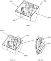
Figure 1 depicts the front perspective view of the invented corner box with a single module. -
Figures 2(a) and 2(b) depict the snap fit locking arrangements provided for attaching two components of the corner box assembly. -
Figure 3 illustrates the alignment of the two end parts of the of the invented corner box for the snapping members to latch with their corresponding receiving member. -
Figures 4(a), 4(b) and 4(c) depict the perspective view of the end part, mid part and mid wall respectively. -
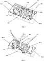
Figure 5 shows the assembled view of the corner box assembly with a mid part interposed between two end parts. -
Figure 6 shows the exploded view of the corner box assembly with a mid part interposed between two end parts. -
Figure 7 shows the assembled view of the corner box assembly with a plurality of mid parts interposed between two end parts. -
Figure 8 shows the exploded view of the corner box assembly with a plurality of mid parts interposed between two end parts. -
Figure 9 is an illustrative block diagram showing the modularity in the assembly of the mid parts and end parts in said corner box assembly. - With reference to
figures 1 and5 of the accompanying drawings, the present invention as disclosed is a corner box assembly (100) used in places where plugging or unplugging is done. The corner box assembly (100) is used to accommodate electrical sockets and switches, thus helping in distribution of power. The corner box assembly (100) as disclosed infigures 1 ,5 and 6 comprises of end parts (102), said end parts (102) being a first end part (102-1) and a second end part (102-2), mid parts (104), mid walls (106), a locking arrangement (110) comprising a primary locking arrangement being linear fixing snaps (110-1), a secondary locking arrangement being adjustable fixing snaps (110-2), mounting means (112) to accommodate said mid walls (106), receiving slots (118) and knock outs (120). The receiving slots (118) are staple-like in shape and hereinafter referred as staple-like receiving slots (118). -
Figure 1 of the accompanying drawings illustrates the invented corner box assembly (100) for accommodating electrical sockets and switches. The corner box assembly (100) comprises of end parts (102), said end parts (102) being a first end part (102-1) and a second end part (102-2). The first end part (102-1) and second end part (102-2) are assembled together to form a corner box assembly (100). The first end part (102-1) and the second end part (102-2) are provided with knock outs (120) for electrical conduits and cable to be inserted into said corner box assembly (100). - The first end part (102-1) and second end part (102-2) are assembled together by said locking arrangement (110) (as shown in
figure 2(a) ). In order to assemble said corner box (100), the first end part (102-1) and the second end part (102-2) are aligned in position. The staple-like receiving slots (118) provided on one of the ends of said first end part (102-1) and second end part (102-2) are aligned with the fixing snaps (110-1,110-2) which thereof helps the user to align two of said end parts (102-1,102-2) in a prerequisite position. Once said end parts (102) are aligned in said prerequisite position, they are then assembled together by means of said locking arrangement (110). - The end parts (102) are assembled by confining the first end part (102-1) in a fixed position and aligning the second end part (102-2) with respect to the first end part (102-1) and thereby pushing the snaps into their corresponding receiving member. The second end part (102-2) is constructed with a matching profile with said first end part (102-1) i.e. second end part (102-2) is congruent and complimentarily attached with the first end part (102-1) avoiding any confusion regarding alignment. This constructional feature helps in aligning the first end part (102-1) and the second end part (102-2) when the same are attached together. The corner box assembly (100) as shown in
figure 1 is provided with knock outs (120) on their rear side. These knock outs (120), when cut open, serve as entry and/or exit points for electrical cables and wires. -
Figures 5 and 6 of the accompanying drawings illustrate the assembled view and the exploded view of said corner box assembly (100). The end parts (102) comprising the first end part (102-1) and the second end part (102-2) are assembled together to form a corner box assembly (100) as illustrated infigure 1 . This corner box assembly (100) (as shown isfigure 1 ) is a single modular design and is capable of accommodating utmost one electrical socket or one switch. If the user requires housing multiple sockets and switches in said corner box assembly (100), the length of said corner box assembly (100) is increased by adding one or more mid parts (104) (as shown infigures 5 and7 ). - The mid parts (104) are provided with mid walls (106). The mid walls (106) help in strengthening or reinforcing the corner box assembly (100), thus preventing bulging effects in the mid portions of said corner box assembly (100). The adjustable fixing snaps (110-2) are provided for avoiding any loose fixation while assembling higher modularity of the invented corner box assembly (100). The mid walls (106) are substantially located at the centre of said mid parts (104). The mid parts (104) are provided with mounting means (112) for accommodating said mid walls (106). According to one embodiment of the invention, the mounting means (112) have grooves in a complimentary manner to that of the grooves provided in the engaging portion of the mid walls (106). Their grooves act out in such a way that the mid walls (106) are securely engaged with the mounting means (112) with a lap fit type locking arrangement. The mid wall(s) (106) acts as separator between the electrical devices and components such as switches, sockets and their different modules sizes. The mid parts (104) are provided with adjustable fixing snaps (110-2) acting as a self-locator provided at one engaging edge (116-1) of said mid parts (104) for aligning said mid parts (104) with second end part (102-2). Then the mid parts (104) are assembled with said first end part (102-1) by receiving the adjustable fixing snaps (110-2) protruding from the engaging edge (116-1) of said first end part (102-1) and the linear snaps (110-1).
- The corner box assembly (100) is provided with a plurality of knock outs (120), said knock outs (120) are openings for electrical cable entry or exit. The corner box assembly (100) illustrated in
figures 7 and 8 depicts five modular arrangement of the corner box and is assembled in following sequence : a first end part (102-1), mid part (104), mid part (104), mid part (104), mid part (104) and second end part (102-2). -
Figure 2(b) shows the enlarged and detailed view of the locking arrangement (110), said locking arrangement (110) removably couples said first end part (102-1) and said second end part (102-2). The adjustable fixing snaps (110-2) provided on said end parts (102) helps in aligning said first end part (102-1) and said second end part (102-2) in a horizontal direction. Upon aligning said end parts (102), the second end part (102-2) is pressed with respect to said first end part (102-1), thus the snap gets clipped with their corresponding receiving members thereby coupling said first end part (102-1) and said second end part (102-2) by means of said locking arrangement (110). In the above said process, the first end part (102-1) is kept fixed position whereas the second end part (102-2) is pressed or vice-versa in order to attach these two components of the corner box assembly (100). Furthermore, the second end part (102-2) is provided with staple-like receiving slots (118) for receiving the adjustable fixing snaps (110-2) and thereby aligning said first end part (102-1) and second end part (102-2) when said second end part (102-2) is engaged with the for coupling with another adjoining mid part (104) or first end part (102-1). Thus the adjustable fixing member (110) helps to assemble the end parts (102) rigidly at the time of installation or on the basis of user requirements.Figures 4(a), 4(b) and 4(c) of the accompanying drawings illustrate the detailed top perspective view of the various components in the invented corner box assembly (100) such as mid parts (104), end parts (102), and mid walls (106). -
Figures 5 and 6 of the accompanying drawings illustrate the corner box assembly (100) with a mid part (104) and a mid wall (106). Here the length of said corner box assembly (100) is increased by adding a mid part (104). The mid part (104) is supported by a mid wall (106). The mid wall (106) reinforces the corner box assembly (100) by engaging with the mounting means (112) provided at the substantially mid position of the inner walls of said mid part (104), and thereby preventing the bulging effect of said corner box assembly (100) for high modularity. The mid part (104) is removably coupled between said end parts (120). The mid part (104) is aligned with the end parts (102) by aligning the adjustable fixing snaps (110-2) with their corresponding staple-like fixing slots (118) and thereafter assembled with the end parts (102) by means of the said locking arrangement (110). - With reference to
figure 6 of the accompanying drawings, the mid parts (104) present in the corner box assembly (100) are provided with two engaging edges (116-1,116-2) and said end parts (102) present in said corner box assembly (100) is provided with an engaging edge (116-1 or 116-2). The engaging edges (116-1,116-2) present in said mid parts (104) and said end parts (102) helps in engaging said mid parts (104) and end parts (102) with an adjoining mid part (104) or end part (102). The corner box assembly (100) shown infigures 5 and 6 is a two modular arrangement and the same is assembled in the following sequence: a first end part (102-1), mid part (104) and second end part (102-2). -
Figure 9 is an illustrative block diagram indicating the arrangement of said mid parts (104) and said end parts (102) in said corner box assembly (100). Here EP means end part(s) (102) and MP meaning mid parts (104). For a single modular design of said corner box assembly (100), end parts (102) i.e. a first end part (102-1) and a second end part (102-2) is used. As per user requirements, the length of said corner box assembly (100) can be increased by increasing the number of mid parts (104). Here infigure 9 the corner box assembly (100) up to a five modular design is displayed. The length of said corner box assembly (100) can be always increased as per user requirements by adding more number of mid parts (104). - As already mentioned the foregoing description is illustrative of the invention and not limitative to its scope; because it will be apparent to persons skilled in the art to devise other alternative embodiments without departing from the broad ambit of the disclosures made herein.
characterized in that, said locking arrangement comprises linear fixing snaps provided at top and bottom end of the mid parts and end parts; and adjustable fixing snaps provided at end parts and mid parts for rigid fixation of higher modularity.
Claims (8)
- A corner box assembly (100) for housing electrical components, said corner box assembly (100) comprising:- at least two end parts (102) comprising a first end part (102-1) and a second end part (102-2), said first end part (102-1) being of matching profile with said second end part (102-2) to removably attach with each other and thereby form said corner box;- one or more mid parts (104) assembled in-between said end parts (102), said mid parts (104) are adopted to attach with said end parts (102) and thereby increasing the length of the corner box assembly (100); and- mid walls (106) acting as separator between different module of said electrical components, attached onto said mid parts (104) for reinforcing said corner box assembly (100);wherein said end parts (102) and mid parts (104) are configured to engage with adjoining mid parts (104) or end parts (102) by means of at least one locking arrangement (110),
and wherein, said locking arrangement (110) comprises linear fixing snaps (110-1) provided at top and bottom edge of the mid parts (104) and end parts (102); and adjustable fixing snaps (110-2) for rigid fixation. - The corner box assembly (100) for housing electrical components as claimed in claim 1, wherein said mid parts (104) are provided with at least two engaging edges (116-1,116-2) for engaging with an adjoining end part (102) or mid part (104).
- The corner box assembly (100) for housing electrical components as claimed in claim 2, wherein said engaging edges (116-1,116-2) of said mid parts (104) comprise said linear fixing snaps (110-1) at the top and bottom edge protruding in an outwardly manner and receiving slots (118) to engage with said linear fixing snaps (110-1) and said adjustable fixing snaps (110-2) protruding in an outwardly manner to engage with said receiving slots (118) of said adjoining end part (102) or mid part (104).
- The corner box assembly (100) for housing electrical components as claimed in any of the above claims 1 to 3, wherein said end parts (102) are provided with at least an engaging edge (116-1 or 116-2) for engaging with an adjoining end part (102) or mid part (104).
- The corner box assembly (100) for housing electrical components as claimed in claim 4, wherein said engaging edge (116-2) of the second end part (102-2) and engaging edge (116-1) of the first end part (102-1) is provided with said adjustable fixing snaps (110-2) protruding in an outwardly manner and receiving slots (118) to engage with said adjustable fixing snaps (110-2) and linear fixing snaps (110-1) at the top and bottom edge to engage with said receiving slots (118) of said adjoining end part (102) or mid part (104).
- The corner box assembly (100) for housing electrical components as claimed in any of the above claims 1 to 5, wherein said receiving slots (118) are staple-like receiving slots (118).
- The corner box assembly (100) for housing electrical components as claimed in any of the above claims 1 to 6, wherein said mid parts (104) are provided with grooved mounting means (112) at the top and bottom inner walls forming a lap joint with said mid walls(106).
- The corner box assembly (100) for housing electrical components as claimed in any of the above claims 1 to 7, wherein said mid parts (104) and end parts (102) are provided with knock outs (120) acting as provision for inserting cables and conduits.
Applications Claiming Priority (1)
| Application Number | Priority Date | Filing Date | Title |
|---|---|---|---|
| IN201931028748 | 2019-07-17 |
Publications (3)
| Publication Number | Publication Date |
|---|---|
| EP3767767A1 true EP3767767A1 (en) | 2021-01-20 |
| EP3767767B1 EP3767767B1 (en) | 2025-07-09 |
| EP3767767C0 EP3767767C0 (en) | 2025-07-09 |
Family
ID=71661670
Family Applications (1)
| Application Number | Title | Priority Date | Filing Date |
|---|---|---|---|
| EP20186135.8A Active EP3767767B1 (en) | 2019-07-17 | 2020-07-16 | Corner box assembly |
Country Status (1)
| Country | Link |
|---|---|
| EP (1) | EP3767767B1 (en) |
Citations (5)
| Publication number | Priority date | Publication date | Assignee | Title |
|---|---|---|---|---|
| US6576835B1 (en) * | 2001-04-02 | 2003-06-10 | Oem Systems Company, Inc. | Multiple gang junction box assembly with multiple wire clamping devices |
| EP1953887A2 (en) | 2007-02-05 | 2008-08-06 | Bticino S.P.A. | Box for wall mounting electrical apparatuses and modular arrangement comprising said box |
| US20110290625A1 (en) * | 2010-05-25 | 2011-12-01 | Leviton Manufacturing Company, Inc. | Universal Box System |
| US8212144B1 (en) * | 2010-01-27 | 2012-07-03 | Arlington Industries, Inc. | Gangable modular electrical box assembly with interlocking modules |
| US9553433B2 (en) * | 2014-04-29 | 2017-01-24 | Thomas & Betts International Llc | Snap-in gangable electrical box |
-
2020
- 2020-07-16 EP EP20186135.8A patent/EP3767767B1/en active Active
Patent Citations (5)
| Publication number | Priority date | Publication date | Assignee | Title |
|---|---|---|---|---|
| US6576835B1 (en) * | 2001-04-02 | 2003-06-10 | Oem Systems Company, Inc. | Multiple gang junction box assembly with multiple wire clamping devices |
| EP1953887A2 (en) | 2007-02-05 | 2008-08-06 | Bticino S.P.A. | Box for wall mounting electrical apparatuses and modular arrangement comprising said box |
| US8212144B1 (en) * | 2010-01-27 | 2012-07-03 | Arlington Industries, Inc. | Gangable modular electrical box assembly with interlocking modules |
| US20110290625A1 (en) * | 2010-05-25 | 2011-12-01 | Leviton Manufacturing Company, Inc. | Universal Box System |
| US9553433B2 (en) * | 2014-04-29 | 2017-01-24 | Thomas & Betts International Llc | Snap-in gangable electrical box |
Also Published As
| Publication number | Publication date |
|---|---|
| EP3767767B1 (en) | 2025-07-09 |
| EP3767767C0 (en) | 2025-07-09 |
Similar Documents
| Publication | Publication Date | Title |
|---|---|---|
| US5961345A (en) | Faceplate system | |
| US5913787A (en) | Communications conduit connector mounting device | |
| US7905737B2 (en) | Center connect single-sided junction block | |
| CA2600103C (en) | Electrical assembly having an outlet with both power and communications connectors | |
| CA2094790C (en) | Electrical outlet box and plate therefor incorporating a rear support bracket | |
| CA2437683C (en) | Electrical floor access module system | |
| US7465178B2 (en) | Raceway with multi-positionable receptacle blocks | |
| US20080280475A1 (en) | Modular electrical system utilizing four wire circuitry | |
| EP0029676A1 (en) | Connector for electrically interconnecting a panel system and a panel system incorporating the connector | |
| US20140099830A1 (en) | One in four out connector | |
| US9692219B2 (en) | In-floor electrical fitting | |
| US7229050B2 (en) | Raceway system | |
| US20170310061A1 (en) | Snap-in electrical receptacle | |
| US20110259883A1 (en) | Sectional plate for wall port incorporating reversible slide hood for wire management | |
| US6605776B1 (en) | Mounting assembly for an electrical distribution block in modular office furniture | |
| US20150111403A1 (en) | Adjustable flat wire raceway | |
| US4627684A (en) | Housing for electrical connectors | |
| AU2019350886A1 (en) | Modular low profile raceway to provide power and/or data connectivity | |
| US11670922B2 (en) | Power and/or data connectivity track system | |
| EP3767767B1 (en) | Corner box assembly | |
| CA2753810C (en) | Block mounted adjustable end | |
| US7341480B2 (en) | Releasable latch assemblies | |
| KR100284568B1 (en) | Table tap | |
| EP1389816B2 (en) | Installation box for electric appliances | |
| CA2519168C (en) | Communications conduit connector mounting device |
Legal Events
| Date | Code | Title | Description |
|---|---|---|---|
| PUAI | Public reference made under article 153(3) epc to a published international application that has entered the european phase |
Free format text: ORIGINAL CODE: 0009012 |
|
| STAA | Information on the status of an ep patent application or granted ep patent |
Free format text: STATUS: REQUEST FOR EXAMINATION WAS MADE |
|
| 17P | Request for examination filed |
Effective date: 20200716 |
|
| AK | Designated contracting states |
Kind code of ref document: A1 Designated state(s): AL AT BE BG CH CY CZ DE DK EE ES FI FR GB GR HR HU IE IS IT LI LT LU LV MC MK MT NL NO PL PT RO RS SE SI SK SM TR |
|
| AX | Request for extension of the european patent |
Extension state: BA ME |
|
| STAA | Information on the status of an ep patent application or granted ep patent |
Free format text: STATUS: EXAMINATION IS IN PROGRESS |
|
| 17Q | First examination report despatched |
Effective date: 20230103 |
|
| GRAP | Despatch of communication of intention to grant a patent |
Free format text: ORIGINAL CODE: EPIDOSNIGR1 |
|
| STAA | Information on the status of an ep patent application or granted ep patent |
Free format text: STATUS: GRANT OF PATENT IS INTENDED |
|
| INTG | Intention to grant announced |
Effective date: 20250317 |
|
| GRAS | Grant fee paid |
Free format text: ORIGINAL CODE: EPIDOSNIGR3 |
|
| GRAA | (expected) grant |
Free format text: ORIGINAL CODE: 0009210 |
|
| STAA | Information on the status of an ep patent application or granted ep patent |
Free format text: STATUS: THE PATENT HAS BEEN GRANTED |
|
| AK | Designated contracting states |
Kind code of ref document: B1 Designated state(s): AL AT BE BG CH CY CZ DE DK EE ES FI FR GB GR HR HU IE IS IT LI LT LU LV MC MK MT NL NO PL PT RO RS SE SI SK SM TR |
|
| REG | Reference to a national code |
Ref country code: GB Ref legal event code: FG4D |
|
| REG | Reference to a national code |
Ref country code: CH Ref legal event code: EP |
|
| REG | Reference to a national code |
Ref country code: IE Ref legal event code: FG4D |
|
| REG | Reference to a national code |
Ref country code: DE Ref legal event code: R096 Ref document number: 602020054102 Country of ref document: DE |
|
| U01 | Request for unitary effect filed |
Effective date: 20250806 |
|
| U07 | Unitary effect registered |
Designated state(s): AT BE BG DE DK EE FI FR IT LT LU LV MT NL PT RO SE SI Effective date: 20250812 |
|
| U20 | Renewal fee for the european patent with unitary effect paid |
Year of fee payment: 6 Effective date: 20250923 |
|
| PG25 | Lapsed in a contracting state [announced via postgrant information from national office to epo] |
Ref country code: IS Free format text: LAPSE BECAUSE OF FAILURE TO SUBMIT A TRANSLATION OF THE DESCRIPTION OR TO PAY THE FEE WITHIN THE PRESCRIBED TIME-LIMIT Effective date: 20251109 |
|
| PGFP | Annual fee paid to national office [announced via postgrant information from national office to epo] |
Ref country code: NO Payment date: 20251028 Year of fee payment: 6 |
|
| PG25 | Lapsed in a contracting state [announced via postgrant information from national office to epo] |
Ref country code: HR Free format text: LAPSE BECAUSE OF FAILURE TO SUBMIT A TRANSLATION OF THE DESCRIPTION OR TO PAY THE FEE WITHIN THE PRESCRIBED TIME-LIMIT Effective date: 20250709 |
|
| PG25 | Lapsed in a contracting state [announced via postgrant information from national office to epo] |
Ref country code: GR Free format text: LAPSE BECAUSE OF FAILURE TO SUBMIT A TRANSLATION OF THE DESCRIPTION OR TO PAY THE FEE WITHIN THE PRESCRIBED TIME-LIMIT Effective date: 20251010 |
|
| PG25 | Lapsed in a contracting state [announced via postgrant information from national office to epo] |
Ref country code: PL Free format text: LAPSE BECAUSE OF FAILURE TO SUBMIT A TRANSLATION OF THE DESCRIPTION OR TO PAY THE FEE WITHIN THE PRESCRIBED TIME-LIMIT Effective date: 20250709 |
|
| PG25 | Lapsed in a contracting state [announced via postgrant information from national office to epo] |
Ref country code: RS Free format text: LAPSE BECAUSE OF FAILURE TO SUBMIT A TRANSLATION OF THE DESCRIPTION OR TO PAY THE FEE WITHIN THE PRESCRIBED TIME-LIMIT Effective date: 20251009 |
|
| PG25 | Lapsed in a contracting state [announced via postgrant information from national office to epo] |
Ref country code: ES Free format text: LAPSE BECAUSE OF FAILURE TO SUBMIT A TRANSLATION OF THE DESCRIPTION OR TO PAY THE FEE WITHIN THE PRESCRIBED TIME-LIMIT Effective date: 20250709 |
|
| REG | Reference to a national code |
Ref country code: CH Ref legal event code: H13 Free format text: ST27 STATUS EVENT CODE: U-0-0-H10-H13 (AS PROVIDED BY THE NATIONAL OFFICE) Effective date: 20260224 |
|
| PG25 | Lapsed in a contracting state [announced via postgrant information from national office to epo] |
Ref country code: SM Free format text: LAPSE BECAUSE OF FAILURE TO SUBMIT A TRANSLATION OF THE DESCRIPTION OR TO PAY THE FEE WITHIN THE PRESCRIBED TIME-LIMIT Effective date: 20250709 |
|
| PG25 | Lapsed in a contracting state [announced via postgrant information from national office to epo] |
Ref country code: CZ Free format text: LAPSE BECAUSE OF FAILURE TO SUBMIT A TRANSLATION OF THE DESCRIPTION OR TO PAY THE FEE WITHIN THE PRESCRIBED TIME-LIMIT Effective date: 20250709 Ref country code: CH Free format text: LAPSE BECAUSE OF NON-PAYMENT OF DUE FEES Effective date: 20250731 |
|
| PG25 | Lapsed in a contracting state [announced via postgrant information from national office to epo] |
Ref country code: SK Free format text: LAPSE BECAUSE OF FAILURE TO SUBMIT A TRANSLATION OF THE DESCRIPTION OR TO PAY THE FEE WITHIN THE PRESCRIBED TIME-LIMIT Effective date: 20250709 |
|
| PLBE | No opposition filed within time limit |
Free format text: ORIGINAL CODE: 0009261 |
|
| STAA | Information on the status of an ep patent application or granted ep patent |
Free format text: STATUS: NO OPPOSITION FILED WITHIN TIME LIMIT |