EP3767754A1 - Connector - Google Patents
Connector Download PDFInfo
- Publication number
- EP3767754A1 EP3767754A1 EP20172429.1A EP20172429A EP3767754A1 EP 3767754 A1 EP3767754 A1 EP 3767754A1 EP 20172429 A EP20172429 A EP 20172429A EP 3767754 A1 EP3767754 A1 EP 3767754A1
- Authority
- EP
- European Patent Office
- Prior art keywords
- projection
- accommodating portion
- contact
- flexible conductor
- connector according
- Prior art date
- Legal status (The legal status is an assumption and is not a legal conclusion. Google has not performed a legal analysis and makes no representation as to the accuracy of the status listed.)
- Granted
Links
Images





Classifications
-
- H—ELECTRICITY
- H01—ELECTRIC ELEMENTS
- H01R—ELECTRICALLY-CONDUCTIVE CONNECTIONS; STRUCTURAL ASSOCIATIONS OF A PLURALITY OF MUTUALLY-INSULATED ELECTRICAL CONNECTING ELEMENTS; COUPLING DEVICES; CURRENT COLLECTORS
- H01R12/00—Structural associations of a plurality of mutually-insulated electrical connecting elements, specially adapted for printed circuits, e.g. printed circuit boards [PCB], flat or ribbon cables, or like generally planar structures, e.g. terminal strips, terminal blocks; Coupling devices specially adapted for printed circuits, flat or ribbon cables, or like generally planar structures; Terminals specially adapted for contact with, or insertion into, printed circuits, flat or ribbon cables, or like generally planar structures
- H01R12/70—Coupling devices
- H01R12/77—Coupling devices for flexible printed circuits, flat or ribbon cables or like structures
- H01R12/778—Coupling parts carrying sockets, clips or analogous counter-contacts
-
- H—ELECTRICITY
- H01—ELECTRIC ELEMENTS
- H01R—ELECTRICALLY-CONDUCTIVE CONNECTIONS; STRUCTURAL ASSOCIATIONS OF A PLURALITY OF MUTUALLY-INSULATED ELECTRICAL CONNECTING ELEMENTS; COUPLING DEVICES; CURRENT COLLECTORS
- H01R12/00—Structural associations of a plurality of mutually-insulated electrical connecting elements, specially adapted for printed circuits, e.g. printed circuit boards [PCB], flat or ribbon cables, or like generally planar structures, e.g. terminal strips, terminal blocks; Coupling devices specially adapted for printed circuits, flat or ribbon cables, or like generally planar structures; Terminals specially adapted for contact with, or insertion into, printed circuits, flat or ribbon cables, or like generally planar structures
- H01R12/50—Fixed connections
- H01R12/59—Fixed connections for flexible printed circuits, flat or ribbon cables or like structures
- H01R12/592—Fixed connections for flexible printed circuits, flat or ribbon cables or like structures connections to contact elements
-
- H—ELECTRICITY
- H01—ELECTRIC ELEMENTS
- H01R—ELECTRICALLY-CONDUCTIVE CONNECTIONS; STRUCTURAL ASSOCIATIONS OF A PLURALITY OF MUTUALLY-INSULATED ELECTRICAL CONNECTING ELEMENTS; COUPLING DEVICES; CURRENT COLLECTORS
- H01R12/00—Structural associations of a plurality of mutually-insulated electrical connecting elements, specially adapted for printed circuits, e.g. printed circuit boards [PCB], flat or ribbon cables, or like generally planar structures, e.g. terminal strips, terminal blocks; Coupling devices specially adapted for printed circuits, flat or ribbon cables, or like generally planar structures; Terminals specially adapted for contact with, or insertion into, printed circuits, flat or ribbon cables, or like generally planar structures
- H01R12/70—Coupling devices
- H01R12/77—Coupling devices for flexible printed circuits, flat or ribbon cables or like structures
-
- H—ELECTRICITY
- H01—ELECTRIC ELEMENTS
- H01R—ELECTRICALLY-CONDUCTIVE CONNECTIONS; STRUCTURAL ASSOCIATIONS OF A PLURALITY OF MUTUALLY-INSULATED ELECTRICAL CONNECTING ELEMENTS; COUPLING DEVICES; CURRENT COLLECTORS
- H01R12/00—Structural associations of a plurality of mutually-insulated electrical connecting elements, specially adapted for printed circuits, e.g. printed circuit boards [PCB], flat or ribbon cables, or like generally planar structures, e.g. terminal strips, terminal blocks; Coupling devices specially adapted for printed circuits, flat or ribbon cables, or like generally planar structures; Terminals specially adapted for contact with, or insertion into, printed circuits, flat or ribbon cables, or like generally planar structures
- H01R12/70—Coupling devices
- H01R12/77—Coupling devices for flexible printed circuits, flat or ribbon cables or like structures
- H01R12/771—Details
-
- H—ELECTRICITY
- H01—ELECTRIC ELEMENTS
- H01R—ELECTRICALLY-CONDUCTIVE CONNECTIONS; STRUCTURAL ASSOCIATIONS OF A PLURALITY OF MUTUALLY-INSULATED ELECTRICAL CONNECTING ELEMENTS; COUPLING DEVICES; CURRENT COLLECTORS
- H01R12/00—Structural associations of a plurality of mutually-insulated electrical connecting elements, specially adapted for printed circuits, e.g. printed circuit boards [PCB], flat or ribbon cables, or like generally planar structures, e.g. terminal strips, terminal blocks; Coupling devices specially adapted for printed circuits, flat or ribbon cables, or like generally planar structures; Terminals specially adapted for contact with, or insertion into, printed circuits, flat or ribbon cables, or like generally planar structures
- H01R12/70—Coupling devices
- H01R12/77—Coupling devices for flexible printed circuits, flat or ribbon cables or like structures
- H01R12/771—Details
- H01R12/774—Retainers
-
- H—ELECTRICITY
- H01—ELECTRIC ELEMENTS
- H01R—ELECTRICALLY-CONDUCTIVE CONNECTIONS; STRUCTURAL ASSOCIATIONS OF A PLURALITY OF MUTUALLY-INSULATED ELECTRICAL CONNECTING ELEMENTS; COUPLING DEVICES; CURRENT COLLECTORS
- H01R13/00—Details of coupling devices of the kinds covered by groups H01R12/70 or H01R24/00 - H01R33/00
- H01R13/02—Contact members
- H01R13/04—Pins or blades for co-operation with sockets
-
- H—ELECTRICITY
- H01—ELECTRIC ELEMENTS
- H01R—ELECTRICALLY-CONDUCTIVE CONNECTIONS; STRUCTURAL ASSOCIATIONS OF A PLURALITY OF MUTUALLY-INSULATED ELECTRICAL CONNECTING ELEMENTS; COUPLING DEVICES; CURRENT COLLECTORS
- H01R13/00—Details of coupling devices of the kinds covered by groups H01R12/70 or H01R24/00 - H01R33/00
- H01R13/02—Contact members
- H01R13/10—Sockets for co-operation with pins or blades
-
- H—ELECTRICITY
- H01—ELECTRIC ELEMENTS
- H01R—ELECTRICALLY-CONDUCTIVE CONNECTIONS; STRUCTURAL ASSOCIATIONS OF A PLURALITY OF MUTUALLY-INSULATED ELECTRICAL CONNECTING ELEMENTS; COUPLING DEVICES; CURRENT COLLECTORS
- H01R13/00—Details of coupling devices of the kinds covered by groups H01R12/70 or H01R24/00 - H01R33/00
- H01R13/73—Means for mounting coupling parts to apparatus or structures, e.g. to a wall
-
- H—ELECTRICITY
- H01—ELECTRIC ELEMENTS
- H01R—ELECTRICALLY-CONDUCTIVE CONNECTIONS; STRUCTURAL ASSOCIATIONS OF A PLURALITY OF MUTUALLY-INSULATED ELECTRICAL CONNECTING ELEMENTS; COUPLING DEVICES; CURRENT COLLECTORS
- H01R12/00—Structural associations of a plurality of mutually-insulated electrical connecting elements, specially adapted for printed circuits, e.g. printed circuit boards [PCB], flat or ribbon cables, or like generally planar structures, e.g. terminal strips, terminal blocks; Coupling devices specially adapted for printed circuits, flat or ribbon cables, or like generally planar structures; Terminals specially adapted for contact with, or insertion into, printed circuits, flat or ribbon cables, or like generally planar structures
- H01R12/50—Fixed connections
- H01R12/59—Fixed connections for flexible printed circuits, flat or ribbon cables or like structures
- H01R12/65—Fixed connections for flexible printed circuits, flat or ribbon cables or like structures characterised by the terminal
- H01R12/67—Fixed connections for flexible printed circuits, flat or ribbon cables or like structures characterised by the terminal insulation penetrating terminals
- H01R12/68—Fixed connections for flexible printed circuits, flat or ribbon cables or like structures characterised by the terminal insulation penetrating terminals comprising deformable portions
-
- H—ELECTRICITY
- H01—ELECTRIC ELEMENTS
- H01R—ELECTRICALLY-CONDUCTIVE CONNECTIONS; STRUCTURAL ASSOCIATIONS OF A PLURALITY OF MUTUALLY-INSULATED ELECTRICAL CONNECTING ELEMENTS; COUPLING DEVICES; CURRENT COLLECTORS
- H01R12/00—Structural associations of a plurality of mutually-insulated electrical connecting elements, specially adapted for printed circuits, e.g. printed circuit boards [PCB], flat or ribbon cables, or like generally planar structures, e.g. terminal strips, terminal blocks; Coupling devices specially adapted for printed circuits, flat or ribbon cables, or like generally planar structures; Terminals specially adapted for contact with, or insertion into, printed circuits, flat or ribbon cables, or like generally planar structures
- H01R12/70—Coupling devices
- H01R12/77—Coupling devices for flexible printed circuits, flat or ribbon cables or like structures
- H01R12/777—Coupling parts carrying pins, blades or analogous contacts
-
- H—ELECTRICITY
- H01—ELECTRIC ELEMENTS
- H01R—ELECTRICALLY-CONDUCTIVE CONNECTIONS; STRUCTURAL ASSOCIATIONS OF A PLURALITY OF MUTUALLY-INSULATED ELECTRICAL CONNECTING ELEMENTS; COUPLING DEVICES; CURRENT COLLECTORS
- H01R12/00—Structural associations of a plurality of mutually-insulated electrical connecting elements, specially adapted for printed circuits, e.g. printed circuit boards [PCB], flat or ribbon cables, or like generally planar structures, e.g. terminal strips, terminal blocks; Coupling devices specially adapted for printed circuits, flat or ribbon cables, or like generally planar structures; Terminals specially adapted for contact with, or insertion into, printed circuits, flat or ribbon cables, or like generally planar structures
- H01R12/70—Coupling devices
- H01R12/77—Coupling devices for flexible printed circuits, flat or ribbon cables or like structures
- H01R12/79—Coupling devices for flexible printed circuits, flat or ribbon cables or like structures connecting to rigid printed circuits or like structures
-
- H—ELECTRICITY
- H01—ELECTRIC ELEMENTS
- H01R—ELECTRICALLY-CONDUCTIVE CONNECTIONS; STRUCTURAL ASSOCIATIONS OF A PLURALITY OF MUTUALLY-INSULATED ELECTRICAL CONNECTING ELEMENTS; COUPLING DEVICES; CURRENT COLLECTORS
- H01R13/00—Details of coupling devices of the kinds covered by groups H01R12/70 or H01R24/00 - H01R33/00
- H01R13/46—Bases; Cases
- H01R13/502—Bases; Cases composed of different pieces
- H01R13/506—Bases; Cases composed of different pieces assembled by snap action of the parts
Definitions
- the present invention relates to a connector, particularly to a connector adapted to be connected to a flexible conductor.
- JP 2018-129244 A discloses a connector shown in FIG. 18 .
- This connector includes a contact 2 and a base member 3 that are disposed on the opposite sides across a flexible substrate 1 to sandwich the flexible substrate 1 therebetween.
- a flexible conductor 4 is exposed on the flexible substrate 1 on the side facing the contact 2, the contact 2 has a projection accommodating portion 5 of concave shape formed to face the flexible conductor 4, and a projection 6 is formed on the base member 3 to project toward the bottom of the flexible substrate 1.
- the projection 6 of the base member 3 is, together with the flexible substrate 1, inserted into the projection accommodating portion 5 of the contact 2 with the flexible substrate 1 being sandwiched between the projection 6 and the contact 2 such that the projection 6 is covered by the flexible substrate 1, the flexible substrate 1 is pressed against the inner surface of the projection accommodating portion 5 of the contact 2 by the projection 6, and the inner surface of the projection accommodating portion 5 makes contact with the flexible conductor 4 exposed on the surface of the flexible substrate 1 accordingly, whereby the contact 2 is electrically connected to the flexible conductor 4.
- the projection accommodating portion 5 of the contact 2 has an inner surface in the shape of a cylindrical tube
- the projection 6 has the shape of a cylindrical column.
- the flexible substrate 1 having the flexible conductor 4 is inserted into the projection accommodating portion 5 of the contact 2 while receiving a tensile force acting in all directions from the point of contact with the top of the projection 6 and thus being stretched.
- the diameter of the projection 6 is set smaller in advance taking into account the possibility that redundant portions of the flexible substrate 1 and the flexible conductor 4 are caught between the lateral surface of the projection 6 and the inner surface of the projection accommodating portion 5, this may cause insufficient contact pressure of the flexible conductor 4 against the inner surface of the projection accommodating portion 5, thus impairing the reliability of electrical connection between the flexible conductor 4 and the contact 2.
- the present invention has been made to solve the foregoing problems and aims at providing a connector that can be smoothly connected to a flexible conductor regardless of the stretchability of the flexible conductor and can ensure the reliability of electrical connection with the flexible conductor.
- a connector according to the present invention is one adapted to be connected to a flexible conductor, the connector comprising:
- FIGS. 1 and 2 show a connector 11 according to Embodiment 1.
- the connector 11 is used as, for example, a garment-side connector portion for fitting a wearable device, and is connected to a flexible substrate 21.
- the connector 11 includes a housing 12 disposed on the flexible substrate 21, and four contacts 13.
- the housing 12 has a recess 12A.
- the four contacts 13 project perpendicularly to the flexible substrate 21 within the recess 12A of the housing 12.
- the flexible substrate 21 is defined as extending along an XY plane, and the direction in which the contacts 13 project is referred to as "+Z direction.”
- the connector 11 further includes, as a pushing member, a base member 14 disposed on the -Z direction side of the flexible substrate 21, and the connector 11 is connected to the flexible substrate 21 with the flexible substrate 21 being sandwiched between the housing 12 and the base member 14.
- the flexible substrate 21 includes a sheet-type substrate body 22 made of an insulating material, and the substrate body 22 has a top surface 22A facing in the +Z direction and a bottom surface 22B facing in the -Z direction.
- Four flexible conductors 23 are disposed to be exposed on the top surface 22A of the substrate body 22.
- the four flexible conductors 23 correspond to the four contacts 13 on a one-to-one basis.
- the flexible conductors 23 may be made of, for instance, a cloth-type conductor such as conductive fiber, or conductive paste applied onto the top surface 22A of the substrate body 22 by printing or another method.
- the substrate body 22 is provided with two through-holes 22C.
- the housing 12 is made of an insulating material such as insulating resin and is provided with four contact through-holes 12B within the recess 12A opening in the +Z direction.
- the recess 12A constitutes a counter connector accommodating portion in which a part of a counter connector (not shown) is to be accommodated.
- the four contact through-holes 12B correspond to the four contacts 13 on a one-to-one basis.
- Two recessed post accommodating portions 12D are formed in positions outside the recess 12A in the XY direction and at a surface 12C of the housing 12 on the -Z direction side.
- the four contacts 13 are plug-type contacts made of a conductive material such as metal, and are to be connected to corresponding contacts of a counter connector (not shown) when a part of the counter connector is accommodated in the recess 12A of the housing 12.
- Each contact 13 has a tubular portion 13A having the shape of a cylindrical tube extending in the Z direction and a contact-side flange 13B extending from the -Z directional end of the tubular portion 13A along an XY plane.
- the contact-side flange 13B has a second surface 13C facing in the -Z direction.
- the base member 14 is made of an insulating material such as insulating resin and has a flat plate portion 14A.
- the flat plate portion 14A has a first surface 14B facing in the +Z direction.
- Four projections 15 project on the first surface 14B.
- two housing fixing posts 16 larger in height than the projections 15 project from the first surface 14B of the flat plate portion 14A.
- the four contact through-holes 12B of the housing 12, the four flexible conductors 23 of the flexible substrate 21, and the four projections 15 of the base member 14 are arranged to correspond to each other in position.
- the two post accommodating portions 12D of the housing 12, the two through-holes 22C of the substrate body 22 of the flexible substrate 21, and the two housing fixing posts 16 of the base member 14 are arranged to correspond to each other in position.
- the through-holes 22C of the substrate body 22 of the flexible substrate 21 have an inside diameter slightly larger than the outside diameter of the housing fixing posts 16 of the base member 14 to allow smooth insertion of the housing fixing posts 16.
- the post accommodating portions 12D of the housing 12 have an inside diameter slightly smaller than the outside diameter of the housing fixing posts 16 of the base member 14, so that when the housing fixing posts 16 are press-fitted into the post accommodating portions 12D, the housing 12 and the base member 14 are fixed to each other.
- the contact through-holes 12B of the housing 12 have an inside diameter larger than the outside diameter of the tubular portions 13A of the contacts 13 and smaller than the outside diameter of the contact-side flanges 13B thereof, thus allowing smooth insertion of the tubular portions 13A of the contacts 13.
- the projection 15 of the base member 14 is in the shape of a cylindrical column extending in the Z direction and having a diameter D1.
- the tubular portion 13A of the contact 13 has a central axis C1 and has the shape of a cylindrical tube extending in the Z direction along the central axis C1 and closed at its +Z directional end.
- the contact-side flange 13B is formed integrally with the -Z directional end of the tubular portion 13A, and a projection accommodating portion 13D of recess shape is provided in the second surface 13C of the contact-side flange 13B facing in the -Z direction.
- the projection accommodating portion 13D is formed inside the tubular portion 13A so as to have an opening end at the second surface 13C of the contact-side flange 13B and in the shape of a cylindrical tube having the central axis C1 as the center.
- the projection accommodating portion 13D has four protruding portions 13E disposed on the inner surface of the projection accommodating portion 13D.
- the four protruding portions 13E are arranged at equal intervals in the circumferential direction of the inner surface of the projection accommodating portion 13D in the vicinity of the opening end of the projection accommodating portion 13D.
- the four protruding portions 13E separately protrude toward the inside of the projection accommodating portion 13D.
- Each protruding portion 13E has an elliptical shape with the major axis extending in the circumferential direction of the inner surface of the projection accommodating portion 13D and the minor axis extending in the Z direction.
- four gap forming portions 13F defined by the inner surface of the projection accommodating portion 13D are each provided between every two adjacent protruding portions 13E.
- a length D2 between, of the four protruding portions 13E, two protruding portions 13E protruding to face each other is smaller than a length D3 between two gap forming portions 13F facing each other and is set smaller than a value obtained by adding a double of the sum of the thickness of the substrate body 22 of the flexible substrate 21 and the thickness of the flexible conductor 23 to the diameter D1 of the projection 15.
- the length D3 between two gap forming portions 13F facing each other is equivalent to the inside diameter of the projection accommodating portion 13D of the shape of a cylindrical tube.
- the contact 13 as above may be manufactured by integrally forming the tubular portion 13A and the contact-side flange 13B by, for example, press working, cutting or cold heading and subsequently bending, i.e., denting parts of the tubular portion 13A near the root portion of the tubular portion 13A into an elliptical shape from four directions, i.e., the +X direction, -X direction, +Y direction and -Y direction toward the inside of the tubular portion 13A.
- the tubular portion 13A is dented in an elliptical shape in the vicinity of the root portion of the tubular portion 13A, the protruding portions 13E protruding toward the inside of the projection accommodating portion 13D are formed, and dents 13G are formed at the outer periphery of the tubular portion 13A as shown in FIG. 5 .
- the two housing fixing posts 16 of the base member 14 are separately inserted into the two through-holes 22C so as to project above the top surface 22A of the substrate body 22 of the flexible substrate 21, the tubular portions 13A of the four contacts 13 are separately inserted into the four contact through-holes 12B of the housing 12 from the - Z direction side, and the tips of the two housing fixing posts 16 of the base member 14 projecting above the top surface 22A of the substrate body 22 of the flexible substrate 21 are separately inserted into the two post accommodating portions 12D of the housing 12.
- the housing 12, the four contacts 13, the flexible substrate 21 and the base member 14 are aligned with each other in the XY direction.
- the housing fixing posts 16 of the base member 14 are larger in height than the projections 15, the housing fixing posts 16 are inserted into the through-holes 22C of the substrate body 22 of the flexible substrate 21 without being affected by the presence of the projections 15.
- the projections 15 of the base member 14 are inserted in the projection accommodating portions 13D of the corresponding contacts 13 with the flexible substrate 21 being sandwiched therebetween, and the first surface 14B of the base member 14 facing in the +Z direction is in contact with the bottom surface 22B of the substrate body 22.
- the contact through-holes 12B of the housing 12 have an inside diameter larger than the outside diameter of the tubular portions 13A of the contacts 13 and smaller than the outside diameter of the contact-side flanges 13B thereof as shown in FIG. 3 , the contact-side flange 13B of each contact 13 is sandwiched between the surface 12C of the housing 12 on the -Z direction side and the flexible conductor 23 disposed on the top surface 22A of the substrate body 22 of the flexible substrate 21, whereby the contacts 13 are fixed relative to the base member 14. Further, the housing 12 and the base member 14 are fixed to each other by press-fitting the two housing fixing posts 16 of the base member 14 into the two post accommodating portions 12D of the housing 12, and thus the process for connecting the connector 11 to the flexible substrate 21 is completed.
- the projections 15 of the base member 14 are inserted into the projection accommodating portions 13D of the corresponding contacts 13 with the surfaces of the projections 15 being covered by the flexible substrate 21. Accordingly, the substrate body 22 of the flexible substrate 21 and the flexible conductors 23 disposed on the top surface 22A of the substrate body 22 are pushed in the Z direction toward the projection accommodating portions 13D by the projections 15 and thereby deform, whereupon the flexible conductors 23 make contact with the inner surfaces of the projection accommodating portions 13D of the corresponding contacts 13 in the direction parallel to the second surface 13C of the contact 13, i.e., the direction along an XY plane.
- the substrate body 22 of the flexible substrate 21 and the flexible conductors 23 disposed on the top surface 22A of the substrate body 22 are inserted into the projection accommodating portions 13D by the projections 15, if the flexible substrate 21 does not have sufficient stretchability, the substrate body 22 and the flexible conductors 23 deform around the points in contact with the tops of the projections 15, and the deformation leads to redundant portions that may be folded and result in creases.
- the four gap forming portions 13F defined by the inner surface of the projection accommodating portion 13D are each provided between every two adjacent protruding portions 13E, and the length D3 between two gap forming portions 13F facing each other is larger than the length D2 between two protruding portions 13E protruding to face each other. Therefore, as shown in FIG. 9 , when the projection 15 is inserted in the projection accommodating portion 13D of the contact 13, a predetermined gap G2 wider than a distance G1 between the lateral surface of the projection 15 and each protruding portion 13E is formed between the lateral surface of the projection 15 and each gap forming portion 13F.
- the predetermined gaps G2 formed between the lateral surface of the projection 15 and the four gap forming portions 13F of the projection accommodating portion 13D of the contact 13 can receive the redundant portions having been generated in the substrate body 22 and the flexible conductor 23.
- the redundant portions of the substrate body 22 and the flexible conductor 23 are to be received in the predetermined gaps G2 while being pressed against the gap forming portions 13F with a force weaker than a pressing force of the lateral surface of the projection 15 against the protruding portions 13E or without being affected by any pressing force against the gap forming portions 13F.
- the projections 15 of the base member 14 can be smoothly inserted into the projection accommodating portions 13D of the contacts 13 with the flexible substrate 21 being sandwiched therebetween so as to connect the connector 11 to the flexible substrate 21, and the reliability of the electrical connection with the flexible conductors 23 can be ensured.
- protruding portions 13E of the projection accommodating portion 13D of the contact 13 have an elliptical shape, this is not the only configuration, and the protruding portions 13E may have a circular shape.
- the substrate body 22 of the flexible substrate 21 and the flexible conductors 23 disposed on the top surface 22A of the substrate body 22 are inserted into the projection accommodating portions 13D of the contacts 13 by the projections 15; however, the invention is not limited thereto.
- FIG. 10 shows an exploded perspective view of a connector 11A according to Embodiment 2.
- the connector 11A is connected to a flexible substrate 21A and has the same configuration as the connector 11 of Embodiment 1 except that the size of the protruding portions 13E of the projection accommodating portion 13D of the contact 13 relative to the diameter D1 of the projection 15 of the base member 14 is changed.
- the connector 11A includes the housing 12, the four contacts 13, and the base member 14 having the four projections 15 projecting thereon.
- the flexible substrate 21A to which the connector 11A is connected includes the sheet-type substrate body 22 made of an insulating material and the four flexible conductors 23, the substrate body 22 has an opening 22D penetrating the substrate body 22, and the four flexible conductors 23 are held on the top surface 22A of the substrate body 22 such that their tips project to the inside of the opening 22D of the substrate body 22.
- the four flexible conductors 23 are made of, for example, conductive fiber and as shown in FIG. 11 , each inserted into the projection accommodating portion 13D of the corresponding contact 13 by the corresponding projection 15 within the opening 22D of the substrate body 22.
- a length D2A between, of the four protruding portions 13E of the projection accommodating portion 13D of the contact 13, two protruding portions 13E protruding to face each other is set to be smaller than a value obtained by adding a double of the thickness of the flexible conductor 23 to the diameter D1 of the projection 15.
- This configuration allows the lateral surface of the projection 15 to press the flexible conductor 23 against the four protruding portions 13E of the contact 13 and thus apply contact pressure, so that the contact 13 is electrically connected to the flexible conductor 23.
- each flexible conductor 23 when each flexible conductor 23 is inserted into the corresponding projection accommodating portion 13D by the corresponding projection 15, redundant portions of the flexible conductor 23 may be generated around the point in contact with the top of the projection 15; however, the predetermined gaps G2 formed between the lateral surface of each projection 15 and the four gap forming portions 13F of the projection accommodating portion 13D of the corresponding contact 13 can receive the redundant portions.
- the projections 15 of the base member 14 can be smoothly inserted into the projection accommodating portions 13D of the contacts 13 with the flexible conductors 23 being sandwiched therebetween so as to connect the connector 11 to the flexible substrate 21A, and the reliability of the electrical connection with the flexible conductors 23 can be ensured.
- the connector 11A according to Embodiment 2 can be connected to the four flexible conductors 23 that are not held by the substrate body 22 and are thus independent as shown in FIG. 12 .
- the four flexible conductors 23 are each inserted into the projection accommodating portion 13D of the corresponding contact 13 by the corresponding projection 15 of the base member 14 and as shown in FIG. 11 , pressed against the four protruding portions 13E of the contact 13 by the lateral surface of the projection 15, while redundant portions of each flexible conductor 23 are received in the predetermined gaps G2 formed between the lateral surface of the projection 15 and the four gap forming portions 13F of the projection accommodating portion 13D of the contact 13.
- the projection accommodating portion 13D of the contact 13 has the four protruding portions 13E arranged at equal intervals in the circumferential direction and the four gap forming portions 13F each formed between every two adjacent protruding portions 13E, the invention is not limited thereto, and the projection accommodating portion 13D of the contact 13 may have one or more protruding portions 13E and one or more gap forming portions 13F.
- the projection accommodating portion 13D may have two protruding portions 13E protruding to face each other across the central axis C1 and two gap forming portions 13F each formed between the two protruding portions 13E.
- the projection accommodating portion 13D may have three protruding portions 13E arranged about the central axis C1 at 120 degree intervals in the circumferential direction and three gap forming portions 13F each formed between every two adjacent protruding portions 13E.
- the distance dimension between the lateral surface of the projection 15 and each protruding portion 13E of the projection accommodating portion 13D be smaller than the thickness dimension of the flexible substrate 21 or the flexible conductor 23 sandwiched between the projection 15 and the projection accommodating portion 13D.
- the projection accommodating portion 13D of the contact 13 has the four protruding portions 13E of elliptical or circular shape, there may be used a contact 31 having four protruding portions 31E linearly extending along the Z direction as shown in FIGS. 13 and 14 .
- the contact 31 has a tubular portion 31A in the shape of a cylindrical tube extending in the Z direction along a central axis C2 and a contact-side flange 31B extending from the -Z directional end of the tubular portion 31A along an XY plane.
- the tubular portion 31A has therein a projection accommodating portion 31D of recess shape that opens toward the -Z direction.
- the projection accommodating portion 31D has the four protruding portions 31E disposed on the inner surface of the projection accommodating portion 31D.
- the four protruding portions 31E have a shape that linearly extends in parallel with the central axis C2 from the vicinity of the opening end of the projection accommodating portion 31D toward the innermost part of the projection accommodating portion 31D.
- Four dents 31G corresponding to those protruding portions 31E are formed at the outer periphery of the tubular portion 31A, accordingly.
- the four protruding portions 31E are arranged at equal intervals in the circumferential direction of the inner surface of the projection accommodating portion 31D, and four gap forming portions 31F defined by the inner surface of the projection accommodating portion 31D are each provided between every two adjacent protruding portions 31E.
- a length between, of the four protruding portions 31E, two protruding portions 31E protruding to face each other is smaller than a length between two gap forming portions 31F facing each other and is set smaller than a value obtained by adding a double of the sum of the thickness of the substrate body 22 of the flexible substrate 21 and the thickness of the flexible conductor 23 to the diameter of the projection 15.
- the lateral surface of the projection 15 presses the flexible conductor 23 against the four protruding portions 31E of the contact 31 and thus applies contact pressure over a predetermined length in the Z direction, so that the contact 31 is electrically connected to the flexible conductor 23.
- Predetermined gaps formed between the lateral surface of the projection 15 and the four gap forming portions 31F of the projection accommodating portion 31D of the contact 31 can receive redundant portions having been generated in the substrate body 22 and the flexible conductor 23 upon insertion of the flexible substrate 21 into the projection accommodating portion 31D.
- the projection 15 of the base member 14 can be smoothly inserted into the projection accommodating portion 31D of the contact 31 with the flexible substrate 21 being sandwiched therebetween so as to connect a connector according to Embodiment 3 to the flexible substrate 21, and the reliability of the electrical connection with the flexible conductor 23 can be ensured.
- a projection 41 as shown in FIG. 16 may be used.
- the projection 41 is made by providing a pointed portion 41B at the top of a projection body 41A in the shape of a cylindrical column, i.e., at the tip thereof in the +Z direction.
- the pointed portion 41B is provided to pierce the flexible substrate 21 having the flexible conductor 23 exposed on its surface or the independent flexible conductor 23 when inserted into the projection accommodating portion 13D, 31D of the contact 13, 31 together with the flexible substrate 21 or the flexible conductor 23.
- the pointed portion 41B has a conical shape sharply pointed in the +Z direction.
- the projection 41 When the projection 41 is inserted into the projection accommodating portion 13D, 31D of the contact 13, 31 with the surface of the projection 41 being covered by the flexible substrate 21 having the flexible conductor 23 exposed on its surface or the independent flexible conductor 23, the flexible substrate 21 or the flexible conductor 23 is pierced to open by the pointed portion 41B of the projection 41, and the projection 41 projects through the opened portion toward the +Z direction side of the flexible substrate 21 or the flexible conductor 23, thus allowing the edge of the opened portion of the flexible substrate 21 or the flexible conductor 23 to conform with the lateral surface of the projection body 41A.
- the lateral surface of the projection body 41A presses the flexible conductor 23 on the flexible substrate 21 or the independent flexible conductor 23 against the four protruding portions 13E, 31E of the projection accommodating portion 13D, 31D of the contact 13, 31, whereby the contact 13, 31 is electrically connected to the flexible conductor 23.
- the pointed portion 41B of the projection 41 pierces the flexible substrate 21 or the flexible conductor 23, the movement of the flexible substrate 21 or the flexible conductor 23 at the top of the projection 41 is restricted, so that the contact 13, 31 can be connected to the flexible substrate 21 or the flexible conductor 23 while suppressing the misalignment.
- the pointed portion 41B of the projection 41 has a conical shape, instead of the conical shape, the pointed portion 41B may be configured to have a linear blade extending toward the +Z direction to cut the flexible substrate 21 or the flexible conductor 23.
- the base member 14 having the four projections 15 is used as a pushing member for pushing the projections 15 into the projection accommodating portions 13D of the contacts 13, the invention is not limited thereto, and as shown in FIG. 17 , a pushing member 51 in which a pushing member-side flange 52 is joined to the root portion of a single projection 15 may also be used.
- the contact 13, 31 can be electrically connected to the flexible conductor 23 on the flexible substrate 21 or the independent flexible conductor 23.
- a pushing member in which a pushing member-side flange is joined to the root portion of a single projection may be formed.
- plug-type contacts 13, 31 are used in Embodiments 1 to 5 above, the invention is not limited thereto, and a connector may be configured such that receptacle-type contacts are connected to the flexible conductors 23 on the flexible substrate 21 or the independent flexible conductors 23 in the same manner.
Landscapes
- Coupling Device And Connection With Printed Circuit (AREA)
Abstract
Description
- The present invention relates to a connector, particularly to a connector adapted to be connected to a flexible conductor.
- As a connector connected to a flexible conductor, for instance,
JP 2018-129244 A FIG. 18 . This connector includes acontact 2 and abase member 3 that are disposed on the opposite sides across a flexible substrate 1 to sandwich the flexible substrate 1 therebetween. - A
flexible conductor 4 is exposed on the flexible substrate 1 on the side facing thecontact 2, thecontact 2 has aprojection accommodating portion 5 of concave shape formed to face theflexible conductor 4, and aprojection 6 is formed on thebase member 3 to project toward the bottom of the flexible substrate 1. When theprojection 6 of thebase member 3 is, together with the flexible substrate 1, inserted into theprojection accommodating portion 5 of thecontact 2 with the flexible substrate 1 being sandwiched between theprojection 6 and thecontact 2 such that theprojection 6 is covered by the flexible substrate 1, the flexible substrate 1 is pressed against the inner surface of theprojection accommodating portion 5 of thecontact 2 by theprojection 6, and the inner surface of theprojection accommodating portion 5 makes contact with theflexible conductor 4 exposed on the surface of the flexible substrate 1 accordingly, whereby thecontact 2 is electrically connected to theflexible conductor 4. - As shown in
FIG. 19 , theprojection accommodating portion 5 of thecontact 2 has an inner surface in the shape of a cylindrical tube, and as shown inFIG. 20 , theprojection 6 has the shape of a cylindrical column. When theprojection 6 is, together with the flexible substrate 1, inserted into theprojection accommodating portion 5 of thecontact 2 with the flexible substrate 1 being sandwiched between theprojection 6 and thecontact 2, theflexible conductor 4 of the flexible substrate 1 is pressed against the inner surface of theprojection accommodating portion 5 by the entire lateral surface of theprojection 6 in the shape of a cylindrical column. - In this process, upon being press-fitted together with the
projection 6 into theprojection accommodating portion 5 of thecontact 2, the flexible substrate 1 having theflexible conductor 4 is inserted into theprojection accommodating portion 5 of thecontact 2 while receiving a tensile force acting in all directions from the point of contact with the top of theprojection 6 and thus being stretched. - However, when the flexible substrate 1 and the
flexible conductor 4 do not have sufficient stretchability, redundant portions of the flexible substrate 1 and theflexible conductor 4 are generated around the points in contact with the top of theprojection 6 and are caught between the lateral surface of theprojection 6 and the inner surface of theprojection accommodating portion 5. - The presence of such redundant portions hinders the insertion of the
projection 6 together with the flexible substrate 1 into theprojection accommodating portion 5 of thecontact 2, and this may make it difficult to smoothly connect the connector to the flexible substrate 1. - Furthermore, if the diameter of the
projection 6 is set smaller in advance taking into account the possibility that redundant portions of the flexible substrate 1 and theflexible conductor 4 are caught between the lateral surface of theprojection 6 and the inner surface of theprojection accommodating portion 5, this may cause insufficient contact pressure of theflexible conductor 4 against the inner surface of theprojection accommodating portion 5, thus impairing the reliability of electrical connection between theflexible conductor 4 and thecontact 2. - The present invention has been made to solve the foregoing problems and aims at providing a connector that can be smoothly connected to a flexible conductor regardless of the stretchability of the flexible conductor and can ensure the reliability of electrical connection with the flexible conductor.
- A connector according to the present invention is one adapted to be connected to a flexible conductor, the connector comprising:
- a pushing member having a projection; and
- a contact made of a conductive material and having a projection accommodating portion of recess shape into which the projection is to be inserted,
- wherein the projection accommodating portion includes: a protruding portion that is situated in an inner surface of the projection accommodating portion with protruding from the inner surface of the projection accommodating portion toward an inside of the projection accommodating portion and approaches a lateral surface of the projection when the projection is inserted into the projection accommodating portion; and a gap forming portion that is situated in the inner surface of the projection accommodating portion around the protruding portion and forms a predetermined gap between the gap forming portion and the lateral surface of the projection when the projection is inserted into the projection accommodating portion, the predetermined gap being wider than a distance between the protruding portion and the lateral surface of the projection, and
- wherein when the projection of the pushing member is inserted in the projection accommodating portion of the contact together with the flexible conductor with the flexible conductor being sandwiched between the projection and the projection accommodating portion of the contact such that the projection of the pushing member is covered by the flexible conductor, the lateral surface of the projection presses the flexible conductor against the protruding portion of the projection accommodating portion to contact the flexible conductor to the protruding portion of the projection accommodating portion, and a redundant portion of the flexible conductor generated upon being inserted into the projection accommodating portion is received in the predetermined gap.
-
-
FIG. 1 is a perspective view showing a connector according to Embodiment 1 of the present invention. -
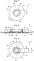
FIG. 2 is a plan view showing the connector according to Embodiment 1. -
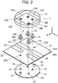
FIG. 3 is an exploded perspective view of the connector according to Embodiment 1. -
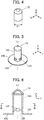
FIG. 4 is a perspective view showing a projection used in the connector according to Embodiment 1. -
FIG. 5 is a perspective view showing a contact used in the connector according to Embodiment 1. -
FIG. 6 is a cross-sectional front view showing the contact used in the connector according to Embodiment 1. -
FIG. 7 is a cross-sectional view taken along line B-B inFIG. 6 . -
FIG. 8 is a cross-sectional view taken along line A-AinFIG. 2 . -
FIG. 9 is a cross-sectional plan view showing a projection and a flexible conductor accommodated in a projection accommodating portion of a contact in Embodiment 1. -
FIG. 10 is an exploded perspective view of a connector according toEmbodiment 2. -
FIG. 11 is a cross-sectional plan view showing a projection and a flexible conductor accommodated in a projection accommodating portion of a contact inEmbodiment 2. -
FIG. 12 is an exploded perspective view of a connector according to a modification ofEmbodiment 2. -
FIG. 13 is a perspective view showing a contact used in a connector according toEmbodiment 3. -
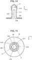
FIG. 14 is a cross-sectional front view showing the contact used in the connector according toEmbodiment 3. -
FIG. 15 is a cross-sectional plan view showing a projection and a flexible conductor accommodated in a projection accommodating portion of the contact inEmbodiment 3. -
FIG. 16 is a perspective view showing a projection used in a connector according toEmbodiment 4. -
FIG. 17 is a perspective view showing a pushing member used in a connector according to Embodiment 5. -
FIG. 18 is a cross-sectional view showing a contact, a projection and a flexible substrate in a conventional connector. -
FIG. 19 is a cross-sectional perspective view showing the contact in the conventional connector. -
FIG. 20 is a perspective view showing the projection in the conventional connector. - Embodiments of the present invention are described below with reference to the accompanying drawings.
-
FIGS. 1 and 2 show aconnector 11 according to Embodiment 1. Theconnector 11 is used as, for example, a garment-side connector portion for fitting a wearable device, and is connected to aflexible substrate 21. - The
connector 11 includes ahousing 12 disposed on theflexible substrate 21, and fourcontacts 13. Thehousing 12 has arecess 12A. The fourcontacts 13 project perpendicularly to theflexible substrate 21 within therecess 12A of thehousing 12. - For convenience, the
flexible substrate 21 is defined as extending along an XY plane, and the direction in which thecontacts 13 project is referred to as "+Z direction." - As shown in
FIG. 3 , theconnector 11 further includes, as a pushing member, abase member 14 disposed on the -Z direction side of theflexible substrate 21, and theconnector 11 is connected to theflexible substrate 21 with theflexible substrate 21 being sandwiched between thehousing 12 and thebase member 14. - The
flexible substrate 21 includes a sheet-type substrate body 22 made of an insulating material, and thesubstrate body 22 has atop surface 22A facing in the +Z direction and abottom surface 22B facing in the -Z direction. Fourflexible conductors 23 are disposed to be exposed on thetop surface 22A of thesubstrate body 22. The fourflexible conductors 23 correspond to the fourcontacts 13 on a one-to-one basis. - The
flexible conductors 23 may be made of, for instance, a cloth-type conductor such as conductive fiber, or conductive paste applied onto thetop surface 22A of thesubstrate body 22 by printing or another method. - The
substrate body 22 is provided with two through-holes 22C. - The
housing 12 is made of an insulating material such as insulating resin and is provided with four contact through-holes 12B within therecess 12A opening in the +Z direction. Therecess 12A constitutes a counter connector accommodating portion in which a part of a counter connector (not shown) is to be accommodated. The four contact through-holes 12B correspond to the fourcontacts 13 on a one-to-one basis. Two recessed post accommodatingportions 12D are formed in positions outside therecess 12A in the XY direction and at asurface 12C of thehousing 12 on the -Z direction side. - The four
contacts 13 are plug-type contacts made of a conductive material such as metal, and are to be connected to corresponding contacts of a counter connector (not shown) when a part of the counter connector is accommodated in therecess 12A of thehousing 12. Eachcontact 13 has atubular portion 13A having the shape of a cylindrical tube extending in the Z direction and a contact-side flange 13B extending from the -Z directional end of thetubular portion 13A along an XY plane. The contact-side flange 13B has asecond surface 13C facing in the -Z direction. - The
base member 14 is made of an insulating material such as insulating resin and has aflat plate portion 14A. Theflat plate portion 14A has afirst surface 14B facing in the +Z direction. Fourprojections 15 project on thefirst surface 14B. In addition, two housing fixing posts 16 larger in height than theprojections 15 project from thefirst surface 14B of theflat plate portion 14A. - As shown in
FIG. 3 , the four contact through-holes 12B of thehousing 12, the fourflexible conductors 23 of theflexible substrate 21, and the fourprojections 15 of thebase member 14 are arranged to correspond to each other in position. - Similarly, the two
post accommodating portions 12D of thehousing 12, the two through-holes 22C of thesubstrate body 22 of theflexible substrate 21, and the two housing fixing posts 16 of thebase member 14 are arranged to correspond to each other in position. - The through-
holes 22C of thesubstrate body 22 of theflexible substrate 21 have an inside diameter slightly larger than the outside diameter of the housing fixing posts 16 of thebase member 14 to allow smooth insertion of the housing fixing posts 16. Further, thepost accommodating portions 12D of thehousing 12 have an inside diameter slightly smaller than the outside diameter of the housing fixing posts 16 of thebase member 14, so that when the housing fixing posts 16 are press-fitted into thepost accommodating portions 12D, thehousing 12 and thebase member 14 are fixed to each other. - The contact through-
holes 12B of thehousing 12 have an inside diameter larger than the outside diameter of thetubular portions 13A of thecontacts 13 and smaller than the outside diameter of the contact-side flanges 13B thereof, thus allowing smooth insertion of thetubular portions 13A of thecontacts 13. - As shown in
FIG. 4 , theprojection 15 of thebase member 14 is in the shape of a cylindrical column extending in the Z direction and having a diameter D1. - As shown in
FIGS. 5 and 6 , thetubular portion 13A of thecontact 13 has a central axis C1 and has the shape of a cylindrical tube extending in the Z direction along the central axis C1 and closed at its +Z directional end. The contact-side flange 13B is formed integrally with the -Z directional end of thetubular portion 13A, and aprojection accommodating portion 13D of recess shape is provided in thesecond surface 13C of the contact-side flange 13B facing in the -Z direction. Specifically, theprojection accommodating portion 13D is formed inside thetubular portion 13A so as to have an opening end at thesecond surface 13C of the contact-side flange 13B and in the shape of a cylindrical tube having the central axis C1 as the center. - The
projection accommodating portion 13D has four protrudingportions 13E disposed on the inner surface of theprojection accommodating portion 13D. The fourprotruding portions 13E are arranged at equal intervals in the circumferential direction of the inner surface of theprojection accommodating portion 13D in the vicinity of the opening end of theprojection accommodating portion 13D. The fourprotruding portions 13E separately protrude toward the inside of theprojection accommodating portion 13D. Each protrudingportion 13E has an elliptical shape with the major axis extending in the circumferential direction of the inner surface of theprojection accommodating portion 13D and the minor axis extending in the Z direction. As shown inFIG. 7 , fourgap forming portions 13F defined by the inner surface of theprojection accommodating portion 13D are each provided between every two adjacent protrudingportions 13E. - A length D2 between, of the four protruding
portions 13E, two protrudingportions 13E protruding to face each other is smaller than a length D3 between twogap forming portions 13F facing each other and is set smaller than a value obtained by adding a double of the sum of the thickness of thesubstrate body 22 of theflexible substrate 21 and the thickness of theflexible conductor 23 to the diameter D1 of theprojection 15. - The length D3 between two
gap forming portions 13F facing each other is equivalent to the inside diameter of theprojection accommodating portion 13D of the shape of a cylindrical tube. - The
contact 13 as above may be manufactured by integrally forming thetubular portion 13A and the contact-side flange 13B by, for example, press working, cutting or cold heading and subsequently bending, i.e., denting parts of thetubular portion 13A near the root portion of thetubular portion 13A into an elliptical shape from four directions, i.e., the +X direction, -X direction, +Y direction and -Y direction toward the inside of thetubular portion 13A. - Since the
tubular portion 13A is dented in an elliptical shape in the vicinity of the root portion of thetubular portion 13A, the protrudingportions 13E protruding toward the inside of theprojection accommodating portion 13D are formed, and dents 13G are formed at the outer periphery of thetubular portion 13A as shown inFIG. 5 . - When the
connector 11 is connected to theflexible substrate 21, first, inFIG. 3 , the two housing fixing posts 16 of thebase member 14 are separately inserted into the two through-holes 22C so as to project above thetop surface 22A of thesubstrate body 22 of theflexible substrate 21, thetubular portions 13A of the fourcontacts 13 are separately inserted into the four contact through-holes 12B of thehousing 12 from the - Z direction side, and the tips of the two housing fixing posts 16 of thebase member 14 projecting above thetop surface 22A of thesubstrate body 22 of theflexible substrate 21 are separately inserted into the twopost accommodating portions 12D of thehousing 12. As a result, thehousing 12, the fourcontacts 13, theflexible substrate 21 and thebase member 14 are aligned with each other in the XY direction. - Since the housing fixing posts 16 of the
base member 14 are larger in height than theprojections 15, the housing fixing posts 16 are inserted into the through-holes 22C of thesubstrate body 22 of theflexible substrate 21 without being affected by the presence of theprojections 15. - In this state, when the
housing 12 and thebase member 14 are pressed against each other in the Z direction to approach each other, thesurface 12C of thehousing 12 on the -Z direction side and thesecond surfaces 13C of the fourcontacts 13 facing in the -Z direction come into contact with thetop surface 22A of thesubstrate body 22, while the fourprojections 15 of thebase member 14 come into contact with thebottom surface 22B of thesubstrate body 22 and subsequently push the contacted portions of theflexible substrate 21 in the +Z direction. - As a result, as shown in
FIG. 8 , theprojections 15 of thebase member 14 are inserted in theprojection accommodating portions 13D of the correspondingcontacts 13 with theflexible substrate 21 being sandwiched therebetween, and thefirst surface 14B of thebase member 14 facing in the +Z direction is in contact with thebottom surface 22B of thesubstrate body 22. - In this state, since the contact through-
holes 12B of thehousing 12 have an inside diameter larger than the outside diameter of thetubular portions 13A of thecontacts 13 and smaller than the outside diameter of the contact-side flanges 13B thereof as shown inFIG. 3 , the contact-side flange 13B of eachcontact 13 is sandwiched between thesurface 12C of thehousing 12 on the -Z direction side and theflexible conductor 23 disposed on thetop surface 22A of thesubstrate body 22 of theflexible substrate 21, whereby thecontacts 13 are fixed relative to thebase member 14. Further, thehousing 12 and thebase member 14 are fixed to each other by press-fitting the two housing fixing posts 16 of thebase member 14 into the twopost accommodating portions 12D of thehousing 12, and thus the process for connecting theconnector 11 to theflexible substrate 21 is completed. - When the
connector 11 is connected to theflexible substrate 21 as described above, theprojections 15 of thebase member 14 are inserted into theprojection accommodating portions 13D of the correspondingcontacts 13 with the surfaces of theprojections 15 being covered by theflexible substrate 21. Accordingly, thesubstrate body 22 of theflexible substrate 21 and theflexible conductors 23 disposed on thetop surface 22A of thesubstrate body 22 are pushed in the Z direction toward theprojection accommodating portions 13D by theprojections 15 and thereby deform, whereupon theflexible conductors 23 make contact with the inner surfaces of theprojection accommodating portions 13D of the correspondingcontacts 13 in the direction parallel to thesecond surface 13C of thecontact 13, i.e., the direction along an XY plane. - At this time, as shown in
FIG. 9 , since the length D2 between two protrudingportions 13E of theprojection accommodating portion 13D of thecontact 13 that protrude to face each other is smaller than the value obtained by adding a double of the sum of the thickness of thesubstrate body 22 of theflexible substrate 21 and the thickness of theflexible conductor 23 to the diameter D1 of theprojection 15, the lateral surface of theprojection 15 is allowed to press theflexible conductor 23 against the four protrudingportions 13E of thecontact 13 and thus apply contact pressure, so that thecontact 13 is electrically connected to theflexible conductor 23. - Further, when the
substrate body 22 of theflexible substrate 21 and theflexible conductors 23 disposed on thetop surface 22A of thesubstrate body 22 are inserted into theprojection accommodating portions 13D by theprojections 15, if theflexible substrate 21 does not have sufficient stretchability, thesubstrate body 22 and theflexible conductors 23 deform around the points in contact with the tops of theprojections 15, and the deformation leads to redundant portions that may be folded and result in creases. - However, as shown in
FIG. 7 , the fourgap forming portions 13F defined by the inner surface of theprojection accommodating portion 13D are each provided between every two adjacent protrudingportions 13E, and the length D3 between twogap forming portions 13F facing each other is larger than the length D2 between two protrudingportions 13E protruding to face each other. Therefore, as shown inFIG. 9 , when theprojection 15 is inserted in theprojection accommodating portion 13D of thecontact 13, a predetermined gap G2 wider than a distance G1 between the lateral surface of theprojection 15 and each protrudingportion 13E is formed between the lateral surface of theprojection 15 and eachgap forming portion 13F. - Thus, the predetermined gaps G2 formed between the lateral surface of the
projection 15 and the fourgap forming portions 13F of theprojection accommodating portion 13D of thecontact 13 can receive the redundant portions having been generated in thesubstrate body 22 and theflexible conductor 23. The redundant portions of thesubstrate body 22 and theflexible conductor 23 are to be received in the predetermined gaps G2 while being pressed against thegap forming portions 13F with a force weaker than a pressing force of the lateral surface of theprojection 15 against the protrudingportions 13E or without being affected by any pressing force against thegap forming portions 13F. - As a result, even when the
substrate body 22 of theflexible substrate 21 and theflexible conductors 23 do not have sufficient stretchability, theprojections 15 of thebase member 14 can be smoothly inserted into theprojection accommodating portions 13D of thecontacts 13 with theflexible substrate 21 being sandwiched therebetween so as to connect theconnector 11 to theflexible substrate 21, and the reliability of the electrical connection with theflexible conductors 23 can be ensured. - While the four protruding
portions 13E of theprojection accommodating portion 13D of thecontact 13 have an elliptical shape, this is not the only configuration, and the protrudingportions 13E may have a circular shape. - In Embodiment 1 above, the
substrate body 22 of theflexible substrate 21 and theflexible conductors 23 disposed on thetop surface 22A of thesubstrate body 22 are inserted into theprojection accommodating portions 13D of thecontacts 13 by theprojections 15; however, the invention is not limited thereto. -
FIG. 10 shows an exploded perspective view of aconnector 11A according toEmbodiment 2. Theconnector 11A is connected to aflexible substrate 21A and has the same configuration as theconnector 11 of Embodiment 1 except that the size of the protrudingportions 13E of theprojection accommodating portion 13D of thecontact 13 relative to the diameter D1 of theprojection 15 of thebase member 14 is changed. Specifically, theconnector 11A includes thehousing 12, the fourcontacts 13, and thebase member 14 having the fourprojections 15 projecting thereon. - While the
flexible substrate 21A to which theconnector 11A is connected includes the sheet-type substrate body 22 made of an insulating material and the fourflexible conductors 23, thesubstrate body 22 has anopening 22D penetrating thesubstrate body 22, and the fourflexible conductors 23 are held on thetop surface 22A of thesubstrate body 22 such that their tips project to the inside of theopening 22D of thesubstrate body 22. - The four
flexible conductors 23 are made of, for example, conductive fiber and as shown inFIG. 11 , each inserted into theprojection accommodating portion 13D of thecorresponding contact 13 by the correspondingprojection 15 within theopening 22D of thesubstrate body 22. - In the
connector 11A ofEmbodiment 2, a length D2A between, of the four protrudingportions 13E of theprojection accommodating portion 13D of thecontact 13, two protrudingportions 13E protruding to face each other is set to be smaller than a value obtained by adding a double of the thickness of theflexible conductor 23 to the diameter D1 of theprojection 15. - This configuration allows the lateral surface of the
projection 15 to press theflexible conductor 23 against the four protrudingportions 13E of thecontact 13 and thus apply contact pressure, so that thecontact 13 is electrically connected to theflexible conductor 23. - Also in
Embodiment 2, when eachflexible conductor 23 is inserted into the correspondingprojection accommodating portion 13D by the correspondingprojection 15, redundant portions of theflexible conductor 23 may be generated around the point in contact with the top of theprojection 15; however, the predetermined gaps G2 formed between the lateral surface of eachprojection 15 and the fourgap forming portions 13F of theprojection accommodating portion 13D of thecorresponding contact 13 can receive the redundant portions. - As a result, even when the
flexible conductors 23 do not have sufficient stretchability, theprojections 15 of thebase member 14 can be smoothly inserted into theprojection accommodating portions 13D of thecontacts 13 with theflexible conductors 23 being sandwiched therebetween so as to connect theconnector 11 to theflexible substrate 21A, and the reliability of the electrical connection with theflexible conductors 23 can be ensured. - Furthermore, the
connector 11A according toEmbodiment 2 can be connected to the fourflexible conductors 23 that are not held by thesubstrate body 22 and are thus independent as shown inFIG. 12 . Also in this case, the fourflexible conductors 23 are each inserted into theprojection accommodating portion 13D of thecorresponding contact 13 by the correspondingprojection 15 of thebase member 14 and as shown inFIG. 11 , pressed against the four protrudingportions 13E of thecontact 13 by the lateral surface of theprojection 15, while redundant portions of eachflexible conductor 23 are received in the predetermined gaps G2 formed between the lateral surface of theprojection 15 and the fourgap forming portions 13F of theprojection accommodating portion 13D of thecontact 13. - While the four
contacts 13 are used inEmbodiments 1 and 2 above, it suffices if at least onecontact 13 is provided. Regardless of the number of thecontacts 13, all of thecontacts 13 can be simultaneously fitted with the correspondingprojections 15 of thebase member 14 by pressing thehousing 12 and thebase member 14 so that they approach each other with theflexible substrate flexible conductors 23 being sandwiched therebetween, and therefore, even when the connector is a multicontact connector having a plurality ofcontacts 13, it is possible to achieve easy connection to and reliable electrical connection with theflexible substrate flexible conductors 23. - While in
Embodiments 1 and 2 above, theprojection accommodating portion 13D of thecontact 13 has the four protrudingportions 13E arranged at equal intervals in the circumferential direction and the fourgap forming portions 13F each formed between every two adjacent protrudingportions 13E, the invention is not limited thereto, and theprojection accommodating portion 13D of thecontact 13 may have one or moreprotruding portions 13E and one or moregap forming portions 13F. - For instance, the
projection accommodating portion 13D may have two protrudingportions 13E protruding to face each other across the central axis C1 and twogap forming portions 13F each formed between the two protrudingportions 13E. Alternatively, theprojection accommodating portion 13D may have three protrudingportions 13E arranged about the central axis C1 at 120 degree intervals in the circumferential direction and threegap forming portions 13F each formed between every two adjacent protrudingportions 13E. - When the
projection 15 is inserted into theprojection accommodating portion 13D of thecontact 13 as above such that the central axis C1 of theprojection accommodating portion 13D coincides with the central axis of theprojection 15 in the shape of a cylindrical column, it is preferable that the distance dimension between the lateral surface of theprojection 15 and each protrudingportion 13E of theprojection accommodating portion 13D be smaller than the thickness dimension of theflexible substrate 21 or theflexible conductor 23 sandwiched between theprojection 15 and theprojection accommodating portion 13D. With this configuration, theflexible conductor 23 can be pressed against the protrudingportions 13E of theprojection accommodating portion 13D with predetermined contact pressure, thus making it possible to establish reliable electrical connection between thecontact 13 and theflexible conductor 23. - While in
Embodiments 1 and 2, theprojection accommodating portion 13D of thecontact 13 has the four protrudingportions 13E of elliptical or circular shape, there may be used acontact 31 having four protrudingportions 31E linearly extending along the Z direction as shown inFIGS. 13 and14 . - The
contact 31 has atubular portion 31A in the shape of a cylindrical tube extending in the Z direction along a central axis C2 and a contact-side flange 31B extending from the -Z directional end of thetubular portion 31A along an XY plane. Thetubular portion 31A has therein aprojection accommodating portion 31D of recess shape that opens toward the -Z direction. - The
projection accommodating portion 31D has the four protrudingportions 31E disposed on the inner surface of theprojection accommodating portion 31D. The fourprotruding portions 31E have a shape that linearly extends in parallel with the central axis C2 from the vicinity of the opening end of theprojection accommodating portion 31D toward the innermost part of theprojection accommodating portion 31D. Fourdents 31G corresponding to those protrudingportions 31E are formed at the outer periphery of thetubular portion 31A, accordingly. - As shown in
FIG. 15 , the four protrudingportions 31E are arranged at equal intervals in the circumferential direction of the inner surface of theprojection accommodating portion 31D, and fourgap forming portions 31F defined by the inner surface of theprojection accommodating portion 31D are each provided between every two adjacent protrudingportions 31E. - A length between, of the four protruding
portions 31E, two protrudingportions 31E protruding to face each other is smaller than a length between twogap forming portions 31F facing each other and is set smaller than a value obtained by adding a double of the sum of the thickness of thesubstrate body 22 of theflexible substrate 21 and the thickness of theflexible conductor 23 to the diameter of theprojection 15. - Even with the thus configured
contact 31, when theprojection 15 is inserted in theprojection accommodating portion 31D of thecontact 31 with the surface of theprojection 15 being covered by theflexible substrate 21, the lateral surface of theprojection 15 presses theflexible conductor 23 against the four protrudingportions 31E of thecontact 31 and thus applies contact pressure over a predetermined length in the Z direction, so that thecontact 31 is electrically connected to theflexible conductor 23. - Predetermined gaps formed between the lateral surface of the
projection 15 and the fourgap forming portions 31F of theprojection accommodating portion 31D of thecontact 31 can receive redundant portions having been generated in thesubstrate body 22 and theflexible conductor 23 upon insertion of theflexible substrate 21 into theprojection accommodating portion 31D. - Therefore, even when the
flexible substrate 21 does not have sufficient stretchability, theprojection 15 of thebase member 14 can be smoothly inserted into theprojection accommodating portion 31D of thecontact 31 with theflexible substrate 21 being sandwiched therebetween so as to connect a connector according toEmbodiment 3 to theflexible substrate 21, and the reliability of the electrical connection with theflexible conductor 23 can be ensured. - In place of the
projection 15 in Embodiments 1 to 3, aprojection 41 as shown inFIG. 16 may be used. Theprojection 41 is made by providing apointed portion 41B at the top of aprojection body 41A in the shape of a cylindrical column, i.e., at the tip thereof in the +Z direction. - The pointed
portion 41B is provided to pierce theflexible substrate 21 having theflexible conductor 23 exposed on its surface or the independentflexible conductor 23 when inserted into theprojection accommodating portion contact flexible substrate 21 or theflexible conductor 23. The pointedportion 41B has a conical shape sharply pointed in the +Z direction. - When the
projection 41 is inserted into theprojection accommodating portion contact projection 41 being covered by theflexible substrate 21 having theflexible conductor 23 exposed on its surface or the independentflexible conductor 23, theflexible substrate 21 or theflexible conductor 23 is pierced to open by the pointedportion 41B of theprojection 41, and theprojection 41 projects through the opened portion toward the +Z direction side of theflexible substrate 21 or theflexible conductor 23, thus allowing the edge of the opened portion of theflexible substrate 21 or theflexible conductor 23 to conform with the lateral surface of theprojection body 41A. - Accordingly, the lateral surface of the
projection body 41A presses theflexible conductor 23 on theflexible substrate 21 or the independentflexible conductor 23 against the four protrudingportions projection accommodating portion contact contact flexible conductor 23. - In this manner, an opening is made in the
flexible substrate 21 or theflexible conductor 23 using the pointedportion 41B of theprojection 41, and the edge of the opened portion of theflexible substrate 21 or theflexible conductor 23 is sandwiched between the lateral surface of theprojection body 41A and the four protrudingportions projection accommodating portion flexible substrate 21 or theflexible conductor 23 is made of a material that is not very stretchable, thecontact flexible conductor 23 without fail. - Further, since the pointed
portion 41B of theprojection 41 pierces theflexible substrate 21 or theflexible conductor 23, the movement of theflexible substrate 21 or theflexible conductor 23 at the top of theprojection 41 is restricted, so that thecontact flexible substrate 21 or theflexible conductor 23 while suppressing the misalignment. - While the pointed
portion 41B of theprojection 41 has a conical shape, instead of the conical shape, the pointedportion 41B may be configured to have a linear blade extending toward the +Z direction to cut theflexible substrate 21 or theflexible conductor 23. - While in Embodiments 1 to 3, the
base member 14 having the fourprojections 15 is used as a pushing member for pushing theprojections 15 into theprojection accommodating portions 13D of thecontacts 13, the invention is not limited thereto, and as shown inFIG. 17 , a pushingmember 51 in which a pushing member-side flange 52 is joined to the root portion of asingle projection 15 may also be used. - When the
projection 15 of the pushingmember 51 as above is inserted into theprojection accommodating portion corresponding contact projection 15 of the pushingmember 51 being covered by theflexible substrate 21 or the independentflexible conductor 23, thecontact flexible conductor 23 on theflexible substrate 21 or the independentflexible conductor 23. - For the
projection 41 inEmbodiments 4, similarly, a pushing member in which a pushing member-side flange is joined to the root portion of a single projection may be formed. - While the plug-
type contacts flexible conductors 23 on theflexible substrate 21 or the independentflexible conductors 23 in the same manner.
Claims (19)
- A connector (11, 11A) adapted to be connected to a flexible conductor (23), the connector comprising:a pushing member (14, 51) having a projection (15, 41); anda contact (13, 31) made of a conductive material and having a projection accommodating portion (13D, 31D) of recess shape into which the projection is to be inserted,wherein the projection accommodating portion (13D, 31D) includes: a protruding portion (13E, 31E) that is situated in an inner surface of the projection accommodating portion with protruding from the inner surface of the projection accommodating portion toward an inside of the projection accommodating portion and approaches a lateral surface of the projection when the projection (15, 41) is inserted into the projection accommodating portion; and a gap forming portion (13F, 31F) that is situated in the inner surface of the projection accommodating portion around the protruding portion and forms a predetermined gap (G2) between the gap forming portion and the lateral surface of the projection when the projection is inserted into the projection accommodating portion, the predetermined gap being wider than a distance between the protruding portion and the lateral surface of the projection, andwherein when the projection (15, 41) of the pushing member is inserted in the projection accommodating portion (13D, 31D) of the contact together with the flexible conductor (23) with the flexible conductor being sandwiched between the projection and the projection accommodating portion of the contact such that the projection of the pushing member is covered by the flexible conductor, the lateral surface of the projection (15, 41) presses the flexible conductor against the protruding portion (13E, 31E) of the projection accommodating portion to contact the flexible conductor to the protruding portion of the projection accommodating portion, and a redundant portion of the flexible conductor generated upon being inserted into the projection accommodating portion is received in the predetermined gap (G2).
- The connector according to claim 1,
wherein a dimension of the distance formed between the protruding portion (13E, 31E) and the lateral surface of the projection (15, 41) when the projection is inserted in the projection accommodating portion is smaller than a thickness dimension of the flexible conductor. - The connector according to claim 1 or 2,
wherein the inner surface of the projection accommodating portion (13D, 31D) is in a shape of a cylindrical tube having a central axis (C1, C2), and the projection accommodating portion includes a plurality of the protruding portions (13E, 31E) arranged at equal intervals in a circumferential direction of the inner surface of the projection accommodating portion and a plurality of the gap forming portions (13F, 31F) each formed between every adjacent two of the plurality of the protruding portions. - The connector according to claim 3,
wherein the projection accommodating portion (13D, 31D) has four protruding portions (13E, 31E) as the plurality of the protruding portions and four gap forming portions (13F, 31F) as the plurality of the gap forming portions. - The connector according to claim 4,
wherein the projection (15, 41) is in a shape of a cylindrical column, and
wherein a distance between two of the four protruding portions of the projection accommodating portion protruding to face each other is smaller than a value obtained by adding a double of a thickness of the flexible conductor to a diameter (D1) of the projection. - The connector according to any one of claims 3-5,
wherein the protruding portion (13E) is disposed near an opening end of the projection accommodating portion (13D) and has a circular or elliptical shape. - The connector according to any one of claims 3-5,
wherein the protruding portion (31E) has a shape that linearly extends in parallel with the central axis (C2) from a vicinity of an opening end of the projection accommodating portion (31D) toward an innermost part of the projection accommodating portion. - The connector according to any one of claims 1-7,
wherein the pushing member comprises a base member (14) having a plurality of the projections (15), and
wherein the plurality of the projections are separately inserted into the projection accommodating portions (13D) of a plurality of the contacts (13) with a plurality of the flexible conductors (23) being sandwiched therebetween. - The connector according to claim 8,
wherein each of the plurality of the contacts (13, 31) has a tubular portion (13A, 31A) and a contact-side flange (13B, 31B) formed at one end of the tubular portion,
wherein the connector further includes a housing (12) having a plurality of contact through-holes (12B) through which the tubular portions of the plurality of the contact pass, each of the plurality of contact through-holes being smaller than the contact-side flange of each of the contacts, and
wherein when the housing is fixed to the base member such that the tubular portions of the plurality of the contacts pass through the plurality of contact through-holes and the contact-side flanges of the plurality of the contacts are pressed against the base member, the plurality of the contacts (13, 31) are fixed to the base member (14). - The connector according to claim 9,
wherein the base member (14) has a housing fixing post (16) projecting higher than the plurality of the projections (15),
wherein the housing (12) has a post accommodating portion (12D) of recess shape, and
wherein the housing fixing post is accommodated in the post accommodating portion to fix the housing to the base member. - The connector according to claim 9 or 10,
wherein the housing (12) is made of an insulating material. - The connector according to any one of claims 9-11,
wherein the housing (12) has a counter connector accommodating portion (12A) for accommodating a part of a counter connector. - The connector according to any one of claims 8-12,
wherein the base member (14) is made of an insulating material. - The connector according to any one of claims 1-7,
wherein the pushing member (51) has a pushing member-side flange (52) joined to a root portion of the projection (15). - The connector according to any one of claims 1-14,
wherein the flexible conductor (23) is disposed to be exposed on a top surface of an insulating substrate body (22), and
wherein the flexible conductor (23) is disposed between the pushing member (14, 51) and the contact (13, 31) such that the flexible conductor faces the projection accommodating portion of the contact and a bottom surface of the insulating substrate body faces the projection of the pushing member. - The connector according to any one of claims 1-14,
wherein the flexible conductor (23) is independently disposed between the pushing member and the contact. - The connector according to any one of claims 1-16,
wherein a pointed portion (41B) for piercing the flexible conductor (23) is formed at a tip of the projection (41). - The connector according to any one of claims 1-17,
wherein the contact is a plug-type contact (13, 31). - The connector according to any one of claims 1-17,
wherein the contact is a receptacle-type contact.
Applications Claiming Priority (1)
| Application Number | Priority Date | Filing Date | Title |
|---|---|---|---|
| JP2019133466A JP7232144B2 (en) | 2019-07-19 | 2019-07-19 | connector |
Publications (2)
| Publication Number | Publication Date |
|---|---|
| EP3767754A1 true EP3767754A1 (en) | 2021-01-20 |
| EP3767754B1 EP3767754B1 (en) | 2022-01-12 |
Family
ID=70482399
Family Applications (1)
| Application Number | Title | Priority Date | Filing Date |
|---|---|---|---|
| EP20172429.1A Active EP3767754B1 (en) | 2019-07-19 | 2020-04-30 | Connector |
Country Status (5)
| Country | Link |
|---|---|
| US (1) | US10868380B1 (en) |
| EP (1) | EP3767754B1 (en) |
| JP (1) | JP7232144B2 (en) |
| CN (1) | CN112242620B (en) |
| DK (1) | DK3767754T3 (en) |
Families Citing this family (13)
| Publication number | Priority date | Publication date | Assignee | Title |
|---|---|---|---|---|
| JP7178956B2 (en) * | 2019-05-17 | 2022-11-28 | 日本航空電子工業株式会社 | Connection method, connection structure and connection terminal assembly |
| JP7265458B2 (en) * | 2019-09-26 | 2023-04-26 | 日本航空電子工業株式会社 | Connector and connection method |
| JP7522642B2 (en) * | 2020-11-18 | 2024-07-25 | 日本航空電子工業株式会社 | connector |
| JP7438085B2 (en) * | 2020-11-18 | 2024-02-26 | 日本航空電子工業株式会社 | connector |
| JP7558095B2 (en) * | 2021-03-19 | 2024-09-30 | 日本航空電子工業株式会社 | Connectors and connection methods |
| JP7558110B2 (en) | 2021-04-26 | 2024-09-30 | 日本航空電子工業株式会社 | Connection method and connector assembly |
| JP7807994B2 (en) * | 2022-06-27 | 2026-01-28 | 日本航空電子工業株式会社 | Sheet-shaped conductive member and connector |
| JP7842404B2 (en) * | 2022-07-20 | 2026-04-08 | 日本航空電子工業株式会社 | Method for manufacturing a sheet-like conductive member, sheet-like conductive member, connector, clothing, and connector mounting method. |
| JP7881403B2 (en) * | 2022-08-04 | 2026-06-29 | 日本航空電子工業株式会社 | connector |
| JP7898340B2 (en) * | 2022-09-14 | 2026-07-31 | 日本航空電子工業株式会社 | connector |
| JP7822290B2 (en) * | 2022-09-28 | 2026-03-02 | 日本航空電子工業株式会社 | connector |
| JP2024065476A (en) * | 2022-10-31 | 2024-05-15 | 日本航空電子工業株式会社 | Connector and connector assembly |
| JP2024094608A (en) * | 2022-12-28 | 2024-07-10 | 日本航空電子工業株式会社 | Connectors and connection methods |
Citations (5)
| Publication number | Priority date | Publication date | Assignee | Title |
|---|---|---|---|---|
| US3881796A (en) * | 1973-03-23 | 1975-05-06 | Itt | Terminal for flat conductor |
| US6394833B1 (en) * | 2001-04-25 | 2002-05-28 | Miraco, Inc. | Flat flexible cable connector |
| US20060148309A1 (en) * | 2005-01-06 | 2006-07-06 | Fujitsu Component Limited | Connector |
| EP3361575A1 (en) * | 2017-02-10 | 2018-08-15 | Japan Aviation Electronics Industry, Ltd. | Connector |
| EP3376601A1 (en) * | 2017-03-17 | 2018-09-19 | Japan Aviation Electronics Industry, Ltd. | Connector |
Family Cites Families (13)
| Publication number | Priority date | Publication date | Assignee | Title |
|---|---|---|---|---|
| JP2005122901A (en) * | 2003-09-08 | 2005-05-12 | Furukawa Electric Co Ltd:The | Connector for flat circuit body and connection structure between the connector and flat circuit body |
| US7033208B1 (en) * | 2005-03-07 | 2006-04-25 | Cheng Uei Precision Industry Co., Ltd. | Flexible printed circuit connector |
| KR20080027260A (en) * | 2005-05-19 | 2008-03-26 | 가호 아베 | Hidden Interface System |
| US20090088652A1 (en) * | 2007-09-28 | 2009-04-02 | Kathleen Tremblay | Physiological sensor placement and signal transmission device |
| JP2010272235A (en) * | 2009-05-19 | 2010-12-02 | Jst Mfg Co Ltd | Flat cable connector and harness including the same |
| JP5899459B2 (en) * | 2011-08-29 | 2016-04-06 | パナソニックIpマネジメント株式会社 | connector |
| WO2017127348A2 (en) * | 2016-01-21 | 2017-07-27 | Vf Imagewear, Inc. | Garment and system for baseball swing analysis |
| JP6734676B2 (en) * | 2016-03-28 | 2020-08-05 | 日本航空電子工業株式会社 | Sliding connector |
| TWI559622B (en) * | 2016-05-05 | 2016-11-21 | 凡甲科技股份有限公司 | Electrical connector |
| JP6826878B2 (en) * | 2016-12-19 | 2021-02-10 | 日本航空電子工業株式会社 | Sliding connector |
| CN106505363B (en) * | 2016-12-23 | 2019-11-26 | 深圳市泰科汉泽精密电子有限公司 | Magnetic pole button |
| JP6995574B2 (en) * | 2017-11-10 | 2022-01-14 | 日本航空電子工業株式会社 | connector |
| JP6942038B2 (en) * | 2017-12-05 | 2021-09-29 | 日本航空電子工業株式会社 | connector |
-
2019
- 2019-07-19 JP JP2019133466A patent/JP7232144B2/en active Active
-
2020
- 2020-04-06 US US16/840,701 patent/US10868380B1/en active Active
- 2020-04-17 CN CN202010309258.5A patent/CN112242620B/en active Active
- 2020-04-30 DK DK20172429.1T patent/DK3767754T3/en active
- 2020-04-30 EP EP20172429.1A patent/EP3767754B1/en active Active
Patent Citations (6)
| Publication number | Priority date | Publication date | Assignee | Title |
|---|---|---|---|---|
| US3881796A (en) * | 1973-03-23 | 1975-05-06 | Itt | Terminal for flat conductor |
| US6394833B1 (en) * | 2001-04-25 | 2002-05-28 | Miraco, Inc. | Flat flexible cable connector |
| US20060148309A1 (en) * | 2005-01-06 | 2006-07-06 | Fujitsu Component Limited | Connector |
| EP3361575A1 (en) * | 2017-02-10 | 2018-08-15 | Japan Aviation Electronics Industry, Ltd. | Connector |
| JP2018129244A (en) | 2017-02-10 | 2018-08-16 | 日本航空電子工業株式会社 | connector |
| EP3376601A1 (en) * | 2017-03-17 | 2018-09-19 | Japan Aviation Electronics Industry, Ltd. | Connector |
Also Published As
| Publication number | Publication date |
|---|---|
| JP2021018906A (en) | 2021-02-15 |
| DK3767754T3 (en) | 2022-02-07 |
| CN112242620B (en) | 2021-12-14 |
| JP7232144B2 (en) | 2023-03-02 |
| EP3767754B1 (en) | 2022-01-12 |
| US10868380B1 (en) | 2020-12-15 |
| CN112242620A (en) | 2021-01-19 |
Similar Documents
| Publication | Publication Date | Title |
|---|---|---|
| EP3767754B1 (en) | Connector | |
| EP3767753B1 (en) | Connector | |
| EP3361575B1 (en) | Connector | |
| US10096918B1 (en) | Connector | |
| EP3435490B1 (en) | Connection assisting member and circuit board assembly | |
| EP3800739A1 (en) | Connector and connecting method | |
| US10483668B2 (en) | Connector and circuit board assembly | |
| EP3226362A1 (en) | Slide connector | |
| US12424774B2 (en) | Connector | |
| EP3813201B1 (en) | Connector and connecting method | |
| US12394931B2 (en) | Connector | |
| EP3799218B1 (en) | Connector | |
| EP3696918B1 (en) | Connecting method, connecting structure and connection terminal | |
| US12230907B2 (en) | Electrical connector for connecting an electric wire to a flat flexible conductor and an electrical connector assembly therefor | |
| JP7011503B2 (en) | Connection auxiliary member and wiring board assembly | |
| US10862254B2 (en) | Coated conductive wire connecting method, coated conductive wire connecting structure and coated conductive wire connecting member | |
| EP4462605A1 (en) | Connector | |
| US20220344844A1 (en) | Connecting method and connector assembly | |
| JP2024078683A (en) | Connector assembly and connection method | |
| US20240145955A1 (en) | Connector and connector assembly |
Legal Events
| Date | Code | Title | Description |
|---|---|---|---|
| PUAI | Public reference made under article 153(3) epc to a published international application that has entered the european phase |
Free format text: ORIGINAL CODE: 0009012 |
|
| STAA | Information on the status of an ep patent application or granted ep patent |
Free format text: STATUS: REQUEST FOR EXAMINATION WAS MADE |
|
| 17P | Request for examination filed |
Effective date: 20200430 |
|
| AK | Designated contracting states |
Kind code of ref document: A1 Designated state(s): AL AT BE BG CH CY CZ DE DK EE ES FI FR GB GR HR HU IE IS IT LI LT LU LV MC MK MT NL NO PL PT RO RS SE SI SK SM TR |
|
| AX | Request for extension of the european patent |
Extension state: BA ME |
|
| RBV | Designated contracting states (corrected) |
Designated state(s): AL AT BE BG CH CY CZ DE DK EE ES FI FR GB GR HR HU IE IS IT LI LT LU LV MC MK MT NL NO PL PT RO RS SE SI SK SM TR |
|
| STAA | Information on the status of an ep patent application or granted ep patent |
Free format text: STATUS: EXAMINATION IS IN PROGRESS |
|
| 17Q | First examination report despatched |
Effective date: 20210408 |
|
| RIC1 | Information provided on ipc code assigned before grant |
Ipc: H01R 12/79 20110101ALN20210707BHEP Ipc: H01R 13/506 20060101ALN20210707BHEP Ipc: H01R 12/77 20110101ALN20210707BHEP Ipc: H01R 12/68 20110101ALN20210707BHEP Ipc: H01R 12/59 20110101AFI20210707BHEP |
|
| GRAP | Despatch of communication of intention to grant a patent |
Free format text: ORIGINAL CODE: EPIDOSNIGR1 |
|
| STAA | Information on the status of an ep patent application or granted ep patent |
Free format text: STATUS: GRANT OF PATENT IS INTENDED |
|
| RAP3 | Party data changed (applicant data changed or rights of an application transferred) |
Owner name: JAPAN AVIATION ELECTRONICS INDUSTRY, LTD. |
|
| RIC1 | Information provided on ipc code assigned before grant |
Ipc: H01R 12/79 20110101ALN20210824BHEP Ipc: H01R 13/506 20060101ALN20210824BHEP Ipc: H01R 12/77 20110101ALN20210824BHEP Ipc: H01R 12/68 20110101ALN20210824BHEP Ipc: H01R 12/59 20110101AFI20210824BHEP |
|
| INTG | Intention to grant announced |
Effective date: 20210913 |
|
| GRAS | Grant fee paid |
Free format text: ORIGINAL CODE: EPIDOSNIGR3 |
|
| GRAA | (expected) grant |
Free format text: ORIGINAL CODE: 0009210 |
|
| STAA | Information on the status of an ep patent application or granted ep patent |
Free format text: STATUS: THE PATENT HAS BEEN GRANTED |
|
| AK | Designated contracting states |
Kind code of ref document: B1 Designated state(s): AL AT BE BG CH CY CZ DE DK EE ES FI FR GB GR HR HU IE IS IT LI LT LU LV MC MK MT NL NO PL PT RO RS SE SI SK SM TR |
|
| REG | Reference to a national code |
Ref country code: GB Ref legal event code: FG4D |
|
| REG | Reference to a national code |
Ref country code: CH Ref legal event code: EP |
|
| REG | Reference to a national code |
Ref country code: DE Ref legal event code: R096 Ref document number: 602020001593 Country of ref document: DE |
|
| REG | Reference to a national code |
Ref country code: IE Ref legal event code: FG4D |
|
| REG | Reference to a national code |
Ref country code: FI Ref legal event code: FGE |
|
| REG | Reference to a national code |
Ref country code: DK Ref legal event code: T3 Effective date: 20220202 |
|
| REG | Reference to a national code |
Ref country code: AT Ref legal event code: REF Ref document number: 1462987 Country of ref document: AT Kind code of ref document: T Effective date: 20220215 |
|
| REG | Reference to a national code |
Ref country code: LT Ref legal event code: MG9D |
|
| REG | Reference to a national code |
Ref country code: NL Ref legal event code: MP Effective date: 20220112 |
|
| REG | Reference to a national code |
Ref country code: AT Ref legal event code: MK05 Ref document number: 1462987 Country of ref document: AT Kind code of ref document: T Effective date: 20220112 |
|
| PG25 | Lapsed in a contracting state [announced via postgrant information from national office to epo] |
Ref country code: NL Free format text: LAPSE BECAUSE OF FAILURE TO SUBMIT A TRANSLATION OF THE DESCRIPTION OR TO PAY THE FEE WITHIN THE PRESCRIBED TIME-LIMIT Effective date: 20220112 |
|
| PG25 | Lapsed in a contracting state [announced via postgrant information from national office to epo] |
Ref country code: SE Free format text: LAPSE BECAUSE OF FAILURE TO SUBMIT A TRANSLATION OF THE DESCRIPTION OR TO PAY THE FEE WITHIN THE PRESCRIBED TIME-LIMIT Effective date: 20220112 Ref country code: RS Free format text: LAPSE BECAUSE OF FAILURE TO SUBMIT A TRANSLATION OF THE DESCRIPTION OR TO PAY THE FEE WITHIN THE PRESCRIBED TIME-LIMIT Effective date: 20220112 Ref country code: PT Free format text: LAPSE BECAUSE OF FAILURE TO SUBMIT A TRANSLATION OF THE DESCRIPTION OR TO PAY THE FEE WITHIN THE PRESCRIBED TIME-LIMIT Effective date: 20220512 Ref country code: NO Free format text: LAPSE BECAUSE OF FAILURE TO SUBMIT A TRANSLATION OF THE DESCRIPTION OR TO PAY THE FEE WITHIN THE PRESCRIBED TIME-LIMIT Effective date: 20220412 Ref country code: LT Free format text: LAPSE BECAUSE OF FAILURE TO SUBMIT A TRANSLATION OF THE DESCRIPTION OR TO PAY THE FEE WITHIN THE PRESCRIBED TIME-LIMIT Effective date: 20220112 Ref country code: HR Free format text: LAPSE BECAUSE OF FAILURE TO SUBMIT A TRANSLATION OF THE DESCRIPTION OR TO PAY THE FEE WITHIN THE PRESCRIBED TIME-LIMIT Effective date: 20220112 Ref country code: ES Free format text: LAPSE BECAUSE OF FAILURE TO SUBMIT A TRANSLATION OF THE DESCRIPTION OR TO PAY THE FEE WITHIN THE PRESCRIBED TIME-LIMIT Effective date: 20220112 Ref country code: BG Free format text: LAPSE BECAUSE OF FAILURE TO SUBMIT A TRANSLATION OF THE DESCRIPTION OR TO PAY THE FEE WITHIN THE PRESCRIBED TIME-LIMIT Effective date: 20220412 |
|
| PG25 | Lapsed in a contracting state [announced via postgrant information from national office to epo] |
Ref country code: PL Free format text: LAPSE BECAUSE OF FAILURE TO SUBMIT A TRANSLATION OF THE DESCRIPTION OR TO PAY THE FEE WITHIN THE PRESCRIBED TIME-LIMIT Effective date: 20220112 Ref country code: LV Free format text: LAPSE BECAUSE OF FAILURE TO SUBMIT A TRANSLATION OF THE DESCRIPTION OR TO PAY THE FEE WITHIN THE PRESCRIBED TIME-LIMIT Effective date: 20220112 Ref country code: GR Free format text: LAPSE BECAUSE OF FAILURE TO SUBMIT A TRANSLATION OF THE DESCRIPTION OR TO PAY THE FEE WITHIN THE PRESCRIBED TIME-LIMIT Effective date: 20220413 Ref country code: AT Free format text: LAPSE BECAUSE OF FAILURE TO SUBMIT A TRANSLATION OF THE DESCRIPTION OR TO PAY THE FEE WITHIN THE PRESCRIBED TIME-LIMIT Effective date: 20220112 |
|
| PG25 | Lapsed in a contracting state [announced via postgrant information from national office to epo] |
Ref country code: IS Free format text: LAPSE BECAUSE OF FAILURE TO SUBMIT A TRANSLATION OF THE DESCRIPTION OR TO PAY THE FEE WITHIN THE PRESCRIBED TIME-LIMIT Effective date: 20220512 |
|
| REG | Reference to a national code |
Ref country code: DE Ref legal event code: R097 Ref document number: 602020001593 Country of ref document: DE |
|
| PG25 | Lapsed in a contracting state [announced via postgrant information from national office to epo] |
Ref country code: SM Free format text: LAPSE BECAUSE OF FAILURE TO SUBMIT A TRANSLATION OF THE DESCRIPTION OR TO PAY THE FEE WITHIN THE PRESCRIBED TIME-LIMIT Effective date: 20220112 Ref country code: SK Free format text: LAPSE BECAUSE OF FAILURE TO SUBMIT A TRANSLATION OF THE DESCRIPTION OR TO PAY THE FEE WITHIN THE PRESCRIBED TIME-LIMIT Effective date: 20220112 Ref country code: RO Free format text: LAPSE BECAUSE OF FAILURE TO SUBMIT A TRANSLATION OF THE DESCRIPTION OR TO PAY THE FEE WITHIN THE PRESCRIBED TIME-LIMIT Effective date: 20220112 Ref country code: EE Free format text: LAPSE BECAUSE OF FAILURE TO SUBMIT A TRANSLATION OF THE DESCRIPTION OR TO PAY THE FEE WITHIN THE PRESCRIBED TIME-LIMIT Effective date: 20220112 Ref country code: CZ Free format text: LAPSE BECAUSE OF FAILURE TO SUBMIT A TRANSLATION OF THE DESCRIPTION OR TO PAY THE FEE WITHIN THE PRESCRIBED TIME-LIMIT Effective date: 20220112 |
|
| PLBE | No opposition filed within time limit |
Free format text: ORIGINAL CODE: 0009261 |
|
| STAA | Information on the status of an ep patent application or granted ep patent |
Free format text: STATUS: NO OPPOSITION FILED WITHIN TIME LIMIT |
|
| PG25 | Lapsed in a contracting state [announced via postgrant information from national office to epo] |
Ref country code: AL Free format text: LAPSE BECAUSE OF FAILURE TO SUBMIT A TRANSLATION OF THE DESCRIPTION OR TO PAY THE FEE WITHIN THE PRESCRIBED TIME-LIMIT Effective date: 20220112 |
|
| 26N | No opposition filed |
Effective date: 20221013 |
|
| REG | Reference to a national code |
Ref country code: BE Ref legal event code: MM Effective date: 20220430 |
|
| PG25 | Lapsed in a contracting state [announced via postgrant information from national office to epo] |
Ref country code: MC Free format text: LAPSE BECAUSE OF FAILURE TO SUBMIT A TRANSLATION OF THE DESCRIPTION OR TO PAY THE FEE WITHIN THE PRESCRIBED TIME-LIMIT Effective date: 20220112 Ref country code: LU Free format text: LAPSE BECAUSE OF NON-PAYMENT OF DUE FEES Effective date: 20220430 |
|
| PG25 | Lapsed in a contracting state [announced via postgrant information from national office to epo] |
Ref country code: SI Free format text: LAPSE BECAUSE OF FAILURE TO SUBMIT A TRANSLATION OF THE DESCRIPTION OR TO PAY THE FEE WITHIN THE PRESCRIBED TIME-LIMIT Effective date: 20220112 Ref country code: BE Free format text: LAPSE BECAUSE OF NON-PAYMENT OF DUE FEES Effective date: 20220430 |
|
| PG25 | Lapsed in a contracting state [announced via postgrant information from national office to epo] |
Ref country code: IE Free format text: LAPSE BECAUSE OF NON-PAYMENT OF DUE FEES Effective date: 20220430 |
|
| PG25 | Lapsed in a contracting state [announced via postgrant information from national office to epo] |
Ref country code: IT Free format text: LAPSE BECAUSE OF FAILURE TO SUBMIT A TRANSLATION OF THE DESCRIPTION OR TO PAY THE FEE WITHIN THE PRESCRIBED TIME-LIMIT Effective date: 20220112 |
|
| PGFP | Annual fee paid to national office [announced via postgrant information from national office to epo] |
Ref country code: DK Payment date: 20230414 Year of fee payment: 4 |
|
| PGFP | Annual fee paid to national office [announced via postgrant information from national office to epo] |
Ref country code: FI Payment date: 20230411 Year of fee payment: 4 |
|
| REG | Reference to a national code |
Ref country code: CH Ref legal event code: PL |
|
| PG25 | Lapsed in a contracting state [announced via postgrant information from national office to epo] |
Ref country code: LI Free format text: LAPSE BECAUSE OF NON-PAYMENT OF DUE FEES Effective date: 20230430 Ref country code: CH Free format text: LAPSE BECAUSE OF NON-PAYMENT OF DUE FEES Effective date: 20230430 |
|
| PG25 | Lapsed in a contracting state [announced via postgrant information from national office to epo] |
Ref country code: MK Free format text: LAPSE BECAUSE OF FAILURE TO SUBMIT A TRANSLATION OF THE DESCRIPTION OR TO PAY THE FEE WITHIN THE PRESCRIBED TIME-LIMIT Effective date: 20220112 Ref country code: CY Free format text: LAPSE BECAUSE OF FAILURE TO SUBMIT A TRANSLATION OF THE DESCRIPTION OR TO PAY THE FEE WITHIN THE PRESCRIBED TIME-LIMIT Effective date: 20220112 |
|
| PG25 | Lapsed in a contracting state [announced via postgrant information from national office to epo] |
Ref country code: HU Free format text: LAPSE BECAUSE OF FAILURE TO SUBMIT A TRANSLATION OF THE DESCRIPTION OR TO PAY THE FEE WITHIN THE PRESCRIBED TIME-LIMIT; INVALID AB INITIO Effective date: 20200430 |
|
| PG25 | Lapsed in a contracting state [announced via postgrant information from national office to epo] |
Ref country code: TR Free format text: LAPSE BECAUSE OF FAILURE TO SUBMIT A TRANSLATION OF THE DESCRIPTION OR TO PAY THE FEE WITHIN THE PRESCRIBED TIME-LIMIT Effective date: 20220112 |
|
| PG25 | Lapsed in a contracting state [announced via postgrant information from national office to epo] |
Ref country code: MT Free format text: LAPSE BECAUSE OF FAILURE TO SUBMIT A TRANSLATION OF THE DESCRIPTION OR TO PAY THE FEE WITHIN THE PRESCRIBED TIME-LIMIT Effective date: 20220112 |
|
| REG | Reference to a national code |
Ref country code: DK Ref legal event code: EBP Effective date: 20240430 |
|
| GBPC | Gb: european patent ceased through non-payment of renewal fee |
Effective date: 20240430 |
|
| PG25 | Lapsed in a contracting state [announced via postgrant information from national office to epo] |
Ref country code: FI Free format text: LAPSE BECAUSE OF NON-PAYMENT OF DUE FEES Effective date: 20240430 |
|
| PG25 | Lapsed in a contracting state [announced via postgrant information from national office to epo] |
Ref country code: GB Free format text: LAPSE BECAUSE OF NON-PAYMENT OF DUE FEES Effective date: 20240430 |
|
| PG25 | Lapsed in a contracting state [announced via postgrant information from national office to epo] |
Ref country code: GB Free format text: LAPSE BECAUSE OF NON-PAYMENT OF DUE FEES Effective date: 20240430 Ref country code: FI Free format text: LAPSE BECAUSE OF NON-PAYMENT OF DUE FEES Effective date: 20240430 |
|
| PG25 | Lapsed in a contracting state [announced via postgrant information from national office to epo] |
Ref country code: DK Free format text: LAPSE BECAUSE OF NON-PAYMENT OF DUE FEES Effective date: 20240430 |
|
| PGFP | Annual fee paid to national office [announced via postgrant information from national office to epo] |
Ref country code: FR Payment date: 20260309 Year of fee payment: 7 |
|
| PGFP | Annual fee paid to national office [announced via postgrant information from national office to epo] |
Ref country code: DE Payment date: 20260305 Year of fee payment: 7 |