EP3767652A1 - Magnetic coupling reactor apparatus - Google Patents
Magnetic coupling reactor apparatus Download PDFInfo
- Publication number
- EP3767652A1 EP3767652A1 EP20181317.7A EP20181317A EP3767652A1 EP 3767652 A1 EP3767652 A1 EP 3767652A1 EP 20181317 A EP20181317 A EP 20181317A EP 3767652 A1 EP3767652 A1 EP 3767652A1
- Authority
- EP
- European Patent Office
- Prior art keywords
- leg core
- parts
- core part
- coil
- magnetic coupling
- Prior art date
- Legal status (The legal status is an assumption and is not a legal conclusion. Google has not performed a legal analysis and makes no representation as to the accuracy of the status listed.)
- Granted
Links
Images





Classifications
-
- H—ELECTRICITY
- H01—ELECTRIC ELEMENTS
- H01F—MAGNETS; INDUCTANCES; TRANSFORMERS; SELECTION OF MATERIALS FOR THEIR MAGNETIC PROPERTIES
- H01F37/00—Fixed inductances not covered by group H01F17/00
-
- H—ELECTRICITY
- H01—ELECTRIC ELEMENTS
- H01F—MAGNETS; INDUCTANCES; TRANSFORMERS; SELECTION OF MATERIALS FOR THEIR MAGNETIC PROPERTIES
- H01F27/00—Details of transformers or inductances, in general
- H01F27/24—Magnetic cores
- H01F27/26—Fastening parts of the core together; Fastening or mounting the core on casing or support
-
- H—ELECTRICITY
- H01—ELECTRIC ELEMENTS
- H01F—MAGNETS; INDUCTANCES; TRANSFORMERS; SELECTION OF MATERIALS FOR THEIR MAGNETIC PROPERTIES
- H01F27/00—Details of transformers or inductances, in general
- H01F27/24—Magnetic cores
- H01F27/26—Fastening parts of the core together; Fastening or mounting the core on casing or support
- H01F27/263—Fastening parts of the core together
-
- H—ELECTRICITY
- H01—ELECTRIC ELEMENTS
- H01F—MAGNETS; INDUCTANCES; TRANSFORMERS; SELECTION OF MATERIALS FOR THEIR MAGNETIC PROPERTIES
- H01F27/00—Details of transformers or inductances, in general
- H01F27/24—Magnetic cores
-
- H—ELECTRICITY
- H01—ELECTRIC ELEMENTS
- H01F—MAGNETS; INDUCTANCES; TRANSFORMERS; SELECTION OF MATERIALS FOR THEIR MAGNETIC PROPERTIES
- H01F27/00—Details of transformers or inductances, in general
- H01F27/28—Coils; Windings; Conductive connections
- H01F27/2823—Wires
-
- H—ELECTRICITY
- H01—ELECTRIC ELEMENTS
- H01F—MAGNETS; INDUCTANCES; TRANSFORMERS; SELECTION OF MATERIALS FOR THEIR MAGNETIC PROPERTIES
- H01F27/00—Details of transformers or inductances, in general
- H01F27/28—Coils; Windings; Conductive connections
- H01F27/2847—Sheets; Strips
-
- H—ELECTRICITY
- H01—ELECTRIC ELEMENTS
- H01F—MAGNETS; INDUCTANCES; TRANSFORMERS; SELECTION OF MATERIALS FOR THEIR MAGNETIC PROPERTIES
- H01F27/00—Details of transformers or inductances, in general
- H01F27/28—Coils; Windings; Conductive connections
- H01F27/30—Fastening or clamping coils, windings, or parts thereof together; Fastening or mounting coils or windings on core, casing, or other support
- H01F27/306—Fastening or mounting coils or windings on core, casing or other support
-
- H—ELECTRICITY
- H01—ELECTRIC ELEMENTS
- H01F—MAGNETS; INDUCTANCES; TRANSFORMERS; SELECTION OF MATERIALS FOR THEIR MAGNETIC PROPERTIES
- H01F27/00—Details of transformers or inductances, in general
- H01F27/34—Special means for preventing or reducing unwanted electric or magnetic effects, e.g. no-load losses, reactive currents, harmonics, oscillations, leakage fields
- H01F27/346—Preventing or reducing leakage fields
-
- H—ELECTRICITY
- H01—ELECTRIC ELEMENTS
- H01F—MAGNETS; INDUCTANCES; TRANSFORMERS; SELECTION OF MATERIALS FOR THEIR MAGNETIC PROPERTIES
- H01F3/00—Cores, Yokes, or armatures
- H01F3/10—Composite arrangements of magnetic circuits
-
- H—ELECTRICITY
- H01—ELECTRIC ELEMENTS
- H01F—MAGNETS; INDUCTANCES; TRANSFORMERS; SELECTION OF MATERIALS FOR THEIR MAGNETIC PROPERTIES
- H01F3/00—Cores, Yokes, or armatures
- H01F3/10—Composite arrangements of magnetic circuits
- H01F3/14—Constrictions; Gaps, e.g. air-gaps
-
- H—ELECTRICITY
- H01—ELECTRIC ELEMENTS
- H01F—MAGNETS; INDUCTANCES; TRANSFORMERS; SELECTION OF MATERIALS FOR THEIR MAGNETIC PROPERTIES
- H01F41/00—Apparatus or processes specially adapted for manufacturing or assembling magnets, inductances or transformers; Apparatus or processes specially adapted for manufacturing materials characterised by their magnetic properties
- H01F41/02—Apparatus or processes specially adapted for manufacturing or assembling magnets, inductances or transformers; Apparatus or processes specially adapted for manufacturing materials characterised by their magnetic properties for manufacturing cores, coils, or magnets
- H01F41/0206—Manufacturing of magnetic cores by mechanical means
- H01F41/0246—Manufacturing of magnetic circuits by moulding or by pressing powder
-
- H—ELECTRICITY
- H01—ELECTRIC ELEMENTS
- H01F—MAGNETS; INDUCTANCES; TRANSFORMERS; SELECTION OF MATERIALS FOR THEIR MAGNETIC PROPERTIES
- H01F41/00—Apparatus or processes specially adapted for manufacturing or assembling magnets, inductances or transformers; Apparatus or processes specially adapted for manufacturing materials characterised by their magnetic properties
- H01F41/02—Apparatus or processes specially adapted for manufacturing or assembling magnets, inductances or transformers; Apparatus or processes specially adapted for manufacturing materials characterised by their magnetic properties for manufacturing cores, coils, or magnets
- H01F41/04—Apparatus or processes specially adapted for manufacturing or assembling magnets, inductances or transformers; Apparatus or processes specially adapted for manufacturing materials characterised by their magnetic properties for manufacturing cores, coils, or magnets for manufacturing coils
- H01F41/06—Coil winding
- H01F41/064—Winding non-flat conductive wires, e.g. rods, cables or cords
-
- H—ELECTRICITY
- H01—ELECTRIC ELEMENTS
- H01F—MAGNETS; INDUCTANCES; TRANSFORMERS; SELECTION OF MATERIALS FOR THEIR MAGNETIC PROPERTIES
- H01F27/00—Details of transformers or inductances, in general
- H01F27/28—Coils; Windings; Conductive connections
- H01F27/32—Insulating of coils, windings, or parts thereof
- H01F27/324—Insulation between coil and core, between different winding sections, around the coil; Other insulation structures
-
- H—ELECTRICITY
- H01—ELECTRIC ELEMENTS
- H01F—MAGNETS; INDUCTANCES; TRANSFORMERS; SELECTION OF MATERIALS FOR THEIR MAGNETIC PROPERTIES
- H01F27/00—Details of transformers or inductances, in general
- H01F27/28—Coils; Windings; Conductive connections
- H01F27/32—Insulating of coils, windings, or parts thereof
- H01F27/324—Insulation between coil and core, between different winding sections, around the coil; Other insulation structures
- H01F27/325—Coil bobbins
Definitions
- the present invention relates to a magnetic coupling reactor apparatus mounted in, for example, an electric vehicle or a hybrid vehicle and more particularly relates to a magnetic coupling reactor apparatus in which a part of a core thereof forming a magnetic path is inserted through a plurality of coil parts so that the coil parts are magnetically coupled.
- a magnetic coupling reactor apparatus As an in-vehicle magnetic coupling reactor, a magnetic coupling reactor apparatus has been known in which a pair of U-shaped cores thereof abuts against each other at the tips of both leg parts so as to form an annular core part, and each of the U leg parts is wound with a coil part so as to form a total of four coil parts. Furthermore, the magnetic coupling reactor causes two coils to generate magnetic fluxes in mutually canceling directions to prevent magnetic saturation of the cores and reduces the ripple using the mutual inductance, achieving size reduction and high efficiency (see Patent Document 1 below).
- Patent Document 1 Japanese Patent No. 6106646
- a magnetic coupling reactor normally uses a pair of U-shaped cores. This makes it difficult to increase the degree of coupling (coupling coefficient), which is a key parameter for low ripple, and tends to increase magnetic leakage. Furthermore, when the degree of coupling is low, the direct current superposition characteristics unfortunately tend to deteriorate.
- the present invention has been made in view of the above circumstances and has an object to provide a magnetic coupling reactor apparatus having an increased degree of coupling over the conventional art, reducing magnetic leakage and enhancing the direct current superposition characteristics.
- the magnetic coupling reactor apparatus includes at least one pair of multi-leg core members made of an iron-based material, in which the at least one pair of multi-leg core members includes: a base core part, and three or more leg core parts projecting from the base core part in an identical direction, wherein the at least one pair of multi-leg core members is disposed so that corresponding leg core parts abut against each other, and at least one coil winding leg core part forming, of the corresponding leg core parts, an inner leg core part except for both outer leg core parts includes an abutting portion of the inner leg core part, a coil part being attached in a winding state to each of the leg core parts sandwiching the abutting portion so as to form a magnetic coupling structure, and when a cross-sectional area of the coil winding leg core part orthogonal to an extending direction of the coil winding leg core part is Si, and a cross-sectional area of each of the outer leg core parts orthogonal to an extending direction of the outer leg
- each of the outer leg core parts needs to satisfy the above expression (1).
- a range of the conditional expression (1) is preferably limited to a range of a conditional expression (2) below. 1.5 ⁇ Si / So ⁇ 3.5
- the range of the conditional expression (1) is further preferably limited to a range of a conditional expression (3) below. 1.5 ⁇ Si / So ⁇ 3.0
- the multi-leg core member is preferably made of an E-shaped core member, and one coil part is preferably attached to a middle leg core part forming the coil winding leg core part of the E-shaped core member in a winding state.
- middle leg core part is preferably offset upward at least by a width of the coil part with respect to the outer leg core parts.
- An input end of the coil part wound around each of the corresponding coil winding leg core parts of the pair of multi-leg core members is preferably disposed on one side with respect to an axis of the multi-leg core member, and winding directions of the coil parts are preferably reversed to each other.
- the input end and an output end of each of the coil parts wound around each of the corresponding coil winding leg core parts of the pair of multi-leg core members are preferably pulled out above an upper end surface of the outer leg core part on one side, and a height of the outer leg core part on the one side is preferably set to be lower by a dimension corresponding to a width of the coil part than a height of the outer leg core part on the other side.
- a corner part of the E-shaped core member preferably has a chamfer extending in a thickness direction of the E-shaped core member.
- An area of a cross section in a direction orthogonal to an axis of the outer leg core part on one side is preferably formed to be equal to an area of a cross section in a direction orthogonal to an axis of the outer leg core part on the other side, and in the two cross sections, the cross section on the one side is preferably formed to be lower in height and wider in width than the cross section on the other side.
- a resin material having a thickness corresponding to a difference in height between the outer leg core part on one side and the outer leg core part on the other side is preferably attached to a portion where an input end and output end of each of the coil parts are not disposed on an upper surface of the outer leg core part on the one side.
- the middle leg core part is preferably provided with one or more air gaps.
- At least one of the outer leg core parts is preferably provided with one or more air gaps.
- the core part is configured by making the iron-based multi-leg core members abut, and the coil part is disposed at each of the opposing inner legs of the multi-leg core members.
- the value of the ratio of the cross-sectional area of the coil winding leg core part with respect to the cross-sectional area of the outer leg core part is set between 1.0 to 5.0.
- the self-inductance can be set to a larger value, and the direct current superposition characteristics can be maintained at a desired value.
- the coil part is disposed at each of at least one pair of opposing inner leg core parts of the multi-leg core members. Accordingly, the coil part is surrounded by the magnetic path, significantly reducing magnetic leakage to the outside.
- the magnetic coupling reactor apparatus of the present embodiment includes a case 108 made of a material with good heat conductivity such as metal (aluminum or the like) having an upper opening, a reactor body 100 stored inside the case 108, and a filler 110 with insulation properties injected between the case 108 and the reactor body 100.
- an E-shaped core having three leg parts disposed so as to project perpendicularly from a base core part (a yoke part hereinafter simply referred to as a base core part) is used.
- a magnetic coupling reactor apparatus 200 is configured to be a magnetic coupling type.
- a main part thereof includes a pair of E-shaped cores 101A and 101B.
- the pair of E-shaped cores 101A and 101B is disposed so that tips of leg parts (both outer leg core parts 101A1 and 101A2, a middle leg core part 101A3, both outer leg core parts 101B1 and 101B2, and a middle leg core part 101B3) projecting perpendicularly from respective base core parts 101A4 and 101B4 face each other, forming a ⁇ -shaped core part as shown in Figure 2 .
- the middle leg core parts 101A3 and 101B3 are respectively wound with coils 103A and 103B.
- corner parts of the E-shaped core 101A are chamfered to form shoulder parts 101C1 and 101C2, and corner parts of the E-shaped core 101B are chamfered to form shoulder parts 101D1 and 101D2. That is, since magnetic fluxes hardly flow through such corner parts, the corner part is chamfered to remove its corner portion, making the entire core compact.
- a core member constituting the core part is made of an iron material.
- an iron-based material can achieve high magnetic density and set a high degree of coupling that tends to decrease by the present structure.
- an iron-based material an electromagnetic steel sheet, a powder magnetic core (pure iron, Fe-Si-AL-based alloy, Ni-Fe-Mo-based alloy, or Ni-Fe-based alloy), amorphous, or the like can be used.
- the tips of the E-shaped cores 101A and 101B may directly abut, a spacer may intervene between both tips, or an air gap may be provided therebetween.
- the coils 103A and 103B are formed by winding the rectangular wires edgewise.
- the rectangular wire is a belt-shaped flat conductive wire, and one having, for example, a thickness of 0.5 to 6.0 mm and a width of 1.0 to 16.0 mm is typically used. Using the rectangular wire can improve the space factor, achieving size reduction and enhancing the skin effect. Alternatively, one having a different cross-sectional shape such as a round wire or a square wire may be used.
- the two coils 103A and 103B are wound so that direct current magnetic fluxes generated therefrom cancel each other out (this will be described later).
- the coils 103A and 103B are cylindrically wound in advance and, when stored in the case 108, respectively fitted to the middle leg core part 101A3 of the E-shaped core 101A and the middle leg core part 101B3 of the E-shaped core 101B, combining with the core part.
- the two coil parts 103A and 103B form a two-phase reactor apparatus, achieving size reduction in the apparatus compared to a case where two one-phase reactor apparatuses are provided.
- the middle leg core part 101A3 of the E-shaped core 101A and the middle leg core part 101B3 of the E-shaped core 101B are respectively provided with the coil parts 103A and 103B. This allows the entire apparatus to have a symmetric shape, achieving efficient magnetic coupling.
- the E-shaped cores 101A and 101B are respectively stored in a state of being embedded in resin molded bodies (including bobbins of the coils 103A and 103B and covers of the cores 101A and 101B) 105A and 105B, and in this state, resin is filled in the mold. Thereby, the E-shaped cores 101A and 101B are formed integrally with the resin molded bodies 105A and 105B.
- the resin molded body 105A insulates the E-shaped core 101A from the coil 103A by intervening therebetween, and the resin molded body 105B insulates the E-shaped core 101B from the coil 103B by intervening therebetween.
- resin molding material for example, unsaturated polyester-based resin, urethane resin, epoxy resin, PBT (polybutylene terephthalate), PPS (polyphenylene sulfide), or the like and the resin molding material to which glass and a heat conductive filler are added can be used.
- FIG 3 is a schematic perspective view of the magnetic coupling reactor apparatus according to the present embodiment.
- the magnetic coupling reactor apparatus 200 is fixed by a screw to a base part (not shown) on which the magnetic coupling reactor apparatus 200 is mounted. That is, the case 108 made of metal such as aluminum includes screw fastening parts 108A on four sides thereof.
- a screw (not shown) is screwed into the base part via a screw hole 108B of the screw fastening part 108A, so that the magnetic coupling reactor apparatus 200 can be mounted on the base part.
- the tips of the above described E-shaped cores 101A and 101B may directly abut, a spacer may intervene therebetween, or one or more air gaps may be provided therebetween.
- one or more air gaps may be provided at the middle leg core parts 101A3 and 101B3, and instead of this or in addition to this, one or more air gaps may be provided at the outer leg core parts 101A1, 101A2, 101B1, and 101B2.
- “one or more air gaps may be provided” refers to a case where the core part is divided into a plurality of parts, and a space is provided between the divided core parts, or a non-magnetic material (for example, PET [polyethylene terephthalate], phenol resin, or the above described resin molding material) is filled between these core parts.
- a non-magnetic material for example, PET [polyethylene terephthalate], phenol resin, or the above described resin molding material
- the case 108 stores the reactor body in which the E-shaped cores 101A and 101B are respectively combined with the coils 103A and 103B.
- the resin molded body (bobbin) 105A can insulate the E-shaped core 101A from the coil 103A by intervening therebetween, and the resin molded body (bobbin) 105B can insulate the E-shaped core 101B from the coil 103B by intervening therebetween.
- the reactor body is restrained from above so as to be fixed inside the case 108.
- the resin molded body (bobbin) is fixed to the case 108 by a bolt 107.
- the case 108 is provided with terminal blocks 106A and 106B made of resin at two positions.
- the terminal block 106A supports a metal terminal 103C1 connected to an input end 103A1 of the coil 103A and a metal terminal 103D1 connected to an input end 103B1 of the coil 103B.
- the terminal block 106B supports a metal terminal 103C2 connected to an output end 103A2 of the coil 103A and a metal terminal 103D2 connected to an output end 103B2 of the coil 103B.
- the case 108 is provided with a thermistor 109 that measures temperature of the reactor body and the filler 110 that fills a gap inside the case 108 to achieve uniform heat distribution.
- the filler 110 can be used by solidifying a liquid or gel material made of, for example, urethane resin, epoxy resin, acrylic resin, silicone resin, or the like and the filler to which a heat conductive filler is added.
- the ratio of a cross-sectional area of the middle leg core part 101A3 with respect to the outer leg core parts 101A1 and 101A2 is specified within a predetermined range, increasing the self-inductance and improving the direct current superposition characteristics.
- a center part thereof is provided with the middle leg core part 101A3 wound with the coil part 103A, and both sides of the middle leg core part 101A3 are respectively provided with the outer leg core parts 101A1 and 101A2.
- the cross-sectional area of the middle leg core part 101A3 is Si
- a cross-sectional area of the outer leg core part 101A1 or 101A2 is So
- a conditional expression (1) below holds.
- the cross section here indicates a cross section in a direction orthogonal to an axis of each leg part. 1.0 ⁇ Si / So ⁇ 5.0
- Figure 5 is a graph showing changes in inductance ( ⁇ H) with respect to the value of Si/So (in Figure 5 , described as middle leg cross-sectional area/outer leg cross-sectional area). According to Figure 5 , the value of Si/So is maximized in the vicinity of 2 to 2.5, and when it is less than 1, the value of inductance sharply decreases.
- the lower limit of Si/So is 1.0, and the upper limit thereof is 5.0.
- the inductance can be about 400 ⁇ H or more, and the self-inductance can be a relatively large value.
- the magnetic coupling reactor apparatus can be configured so as to further improve the direct current superposition characteristics.
- conditional expression (2) a conditional expression (2) below is further desirable. 1.5 ⁇ Si / So ⁇ 3.5
- the inductance can be about 450 ⁇ H or more, and the self-inductance can be a larger value.
- the magnetic coupling reactor apparatus can be configured so as to further improve the direct current superposition characteristics.
- conditional expression (3) a conditional expression (3) below is further desirable.
- the inductance can be 450 ⁇ H or more, and the self-inductance can be a larger value. Furthermore, the direct current superposition characteristics can be further improved.
- the center part thereof is provided with the middle leg core part 101A3 wound with the coil part 103A, and both sides of the middle leg core part 101A3 are respectively provided with the outer leg core parts 101A1 and 101A2.
- the filler 110 is injected between the members.
- the input end 103A1 and the output end 103A2 are pulled out from the wound coil 103A in the lateral direction in the figure.
- the pulled-out input end 103A1 is placed on the bobbin 105A above the outer leg core part 101A2, and the pulled-out output end 103A2 is placed on the bobbin 105A above the outer leg core part 101A1.
- the height of the coil 103A in Figure 6 becomes the smallest when an upper side of the winding part is aligned with the pulled-out input end 103A1 and the pulled-out output end 103A2.
- the middle leg core part 101A3 is disposed so as to be offset upward with respect to the outer leg core parts 101A1 and 101A2.
- the middle leg core part 101A3 thereby fits within a hollow part of the coil 103A, ensuring reduction in height of the reactor body.
- a heat conductive member 111 is disposed between a lower surface of the coil 103A and a heat sink, which is not shown.
- the coil 103A is placed on the heat conductive member 111.
- a member surface abutting against the heat sink can be flat. This improves heat conduction efficiency with respect to the heat sink, resulting in improved heat dissipation.
- the offset amount of the middle leg core part 101A3 is obtained by adding the width of the coil 103A to the distance for ensuring insulation and ⁇ , which is the sum of the assembly margins.
- the terminal block 106A of the magnetic coupling reactor apparatus 200 is provided with end connection parts 103C1 and 103D1.
- a current from the end connection part 103C1 is input from the input end 103A1 of the coil into the coil 103A
- a current from the end connection part 103D1 is input from the input end 103B1 of the coil into the coil 103B. That is, current input ends of the two coils 103A and 103B are respectively positioned at one sides of the coils 103A and 103B.
- the terminal block 106B is provided with the end connection parts 103C2 and 103D2.
- a current from the coil 103A is output via the output end 103A2 to the end connection part 103C2, and a current from the coil 103B is output via the output end 103B2 to the end connection part 103D2. That is, current output ends of the two coils 103A and 103B are respectively aligned so as to be positioned at the other sides of the coils 103A and 103B opposite to the current input parts.
- the positions of the input ends of the two coils 103A and 103B are aligned, and the positions of the output ends thereof are aligned. This improves efficiency of, for example, design around the terminal part. Additionally, magnetic fluxes penetrating the coils 103A and 103B when currents flow thereto need to flow in the opposite directions so as to be canceled out. Accordingly, the winding directions of the coils 103A and 103B are reversed to each other between the two coils 103A and 103B.
- a reactor body 100A similarly to the reactor body 100 of the magnetic coupling reactor apparatus 200 shown in Figure 3 , a reactor body 100A includes the pair of E-shaped cores 101A and 101B and the pair of coils 103A and 103B.
- an input end 113A1 and output end 113A2 of a coil 113A are all pulled out to one side of the coil 103A
- an input end 113B1 and output end 113B2 of a coil 113B are all pulled out to one side of the coil 103B.
- the height of the outer leg core part 101A2 on the side from which the coil 103A is pulled out is formed to be lower by the width of the coil 113A than the heights of the outer leg core part 101A1 on the other side and the base core part 101A4.
- the height of the outer leg core part 101B2 on the side from which the coil 103B is pulled out is formed to be lower by the width of the coil 113B than the heights of the outer leg core part 101B1 on the other side and the base core part 101B4. This enhances the self-inductance and reduces loss in the wiring.
- the cross-sectional areas of the outer leg core parts 101A2 and 101B2 on one side are desirably formed to be equal to those of the outer leg core parts 101A1 and 101B1 on the other side, respectively.
- the lateral widths of the outer leg core parts 101A2 and 101B2 on one side are respectively made longer than those of the outer leg core parts 101A1 and 101B1 on the other side, as shown in a magnetic coupling reactor apparatus 200A in Figure 8 .
- the filler 110 filled for a heat dissipation effect may only be filled to the heights of the outer leg core parts 101A2 and 101B2.
- a resin member 121 made of a material different from the filler 110 is disposed at upper regions of the outer leg core parts 101A2 and 101B2 so that the heights of the outer leg core parts 101A2 and 101B2 including the resin member 121 are approximately the same as those of the outer leg core parts 101A1 and 101B1.
- the filler 110 can be filled to the heights of the outer leg core parts 101A1 and 101B1. This improves heat dissipation performance.
- the resin member 121 is desirably a flowable material for facilitating the filling, and more desirably an inexpensive insulative material.
- Suitable examples of the specific material include phenol resin and PPS (polyphenylene sulfide resin).
- the coil parts 103A and 103B are cylindrically formed in advance, and the E-shaped cores 101A and 101B are respectively inserted into the hollow parts of the coils 103A and 103B. Thereby, the coils 103A and 103B are formed to be respectively wound around the E-shaped cores 101A and 101B.
- the magnetic coupling reactor apparatus of the present invention is not limited to the above embodiment and can be modified in various ways.
- the core part is formed by combining two E-shaped cores whose three leg core parts project from the base core part
- the magnetic coupling reactor apparatus of the present invention can include any number of two or more multi-leg core members whose any number of four or more leg core parts project from the base core part.
- each multi-leg core member can include any polyphase having two or more phases.
- a cross-sectional shape of the multi-leg core member may not be rectangular and may be another shape such as a circle or an ellipse.
- any number of coils may be provided for the individual middle leg core parts 101A3 and 101B3. Note that it is preferable that a symmetrical form is configured as a whole.
- the two coil parts 103A and 103B are wound in directions in which the generating magnetic fluxes in the middle leg core parts 101A3 and 101B3 cancel each other out. Accordingly, it is preferable that the directions of the currents supplied to both coil parts are the same, and the rectangular wires are wound in the opposite directions as described above. Additionally, the directions of the currents supplied to both coils 103A and 103B are reversed, and the rectangular wires are wound in the identical direction, thereby obtaining a function in which the magnetic fluxes generated in the coils 103A and 103B cancel each other out.
- a pair of iron-based E-shaped cores 101A and 101B is disposed so that middle leg core parts 101A3 and 101B3 abut against each other, and coils 103A and 103B are respectively attached to the middle leg core parts 101A3 and 101B3 in a winding state. Furthermore, when a cross-sectional area of the middle leg core part 101A3 or 101B3 orthogonal to an extending direction thereof is Si, and a cross-sectional area of an outer leg core part 101A1, 101B1, 101A2, or 101B2 orthogonal to an extending direction thereof is So, a conditional expression (1) below holds. 1.0 ⁇ Si / So ⁇ 5.0
Landscapes
- Engineering & Computer Science (AREA)
- Power Engineering (AREA)
- Manufacturing & Machinery (AREA)
- Chemical & Material Sciences (AREA)
- Composite Materials (AREA)
- Dc-Dc Converters (AREA)
- Coils Of Transformers For General Uses (AREA)
- Insulating Of Coils (AREA)
Abstract
Description
- The present invention relates to a magnetic coupling reactor apparatus mounted in, for example, an electric vehicle or a hybrid vehicle and more particularly relates to a magnetic coupling reactor apparatus in which a part of a core thereof forming a magnetic path is inserted through a plurality of coil parts so that the coil parts are magnetically coupled.
- As an in-vehicle magnetic coupling reactor, a magnetic coupling reactor apparatus has been known in which a pair of U-shaped cores thereof abuts against each other at the tips of both leg parts so as to form an annular core part, and each of the U leg parts is wound with a coil part so as to form a total of four coil parts. Furthermore, the magnetic coupling reactor causes two coils to generate magnetic fluxes in mutually canceling directions to prevent magnetic saturation of the cores and reduces the ripple using the mutual inductance, achieving size reduction and high efficiency (see
Patent Document 1 below). - [Patent Document 1] Japanese Patent No.
6106646 - As described above, a magnetic coupling reactor normally uses a pair of U-shaped cores. This makes it difficult to increase the degree of coupling (coupling coefficient), which is a key parameter for low ripple, and tends to increase magnetic leakage. Furthermore, when the degree of coupling is low, the direct current superposition characteristics unfortunately tend to deteriorate.
- The present invention has been made in view of the above circumstances and has an object to provide a magnetic coupling reactor apparatus having an increased degree of coupling over the conventional art, reducing magnetic leakage and enhancing the direct current superposition characteristics.
- To solve the above problems, the magnetic coupling reactor apparatus according to the present invention includes
at least one pair of multi-leg core members made of an iron-based material, in which the at least one pair of multi-leg core members includes: a base core part, and three or more leg core parts projecting from the base core part in an identical direction,
wherein the at least one pair of multi-leg core members is disposed so that corresponding leg core parts abut against each other, and at least one coil winding leg core part forming, of the corresponding leg core parts, an inner leg core part except for both outer leg core parts includes an abutting portion of the inner leg core part, a coil part being attached in a winding state to each of the leg core parts sandwiching the abutting portion so as to form a magnetic coupling structure, and
when a cross-sectional area of the coil winding leg core part orthogonal to an extending direction of the coil winding leg core part is Si, and a cross-sectional area of each of the outer leg core parts orthogonal to an extending direction of the outer leg core parts is So, a conditional expression (1) below holds.
- Here, regarding "a cross-sectional area of each of the outer leg core parts," when the cross-sectional areas of the outer leg core parts differ from each other, each of the outer leg core parts needs to satisfy the above expression (1).
- A range of the conditional expression (1) is preferably limited to a range of a conditional expression (2) below.

- Furthermore, the range of the conditional expression (1) is further preferably limited to a range of a conditional expression (3) below.

- The multi-leg core member is preferably made of an E-shaped core member, and
one coil part is preferably attached to a middle leg core part forming the coil winding leg core part of the E-shaped core member in a winding state. - Furthermore, the middle leg core part is preferably offset upward at least by a width of the coil part with respect to the outer leg core parts.
- An input end of the coil part wound around each of the corresponding coil winding leg core parts of the pair of multi-leg core members is preferably disposed on one side with respect to an axis of the multi-leg core member, and winding directions of the coil parts are preferably reversed to each other.
- The input end and an output end of each of the coil parts wound around each of the corresponding coil winding leg core parts of the pair of multi-leg core members are preferably pulled out above an upper end surface of the outer leg core part on one side, and a height of the outer leg core part on the one side is preferably set to be lower by a dimension corresponding to a width of the coil part than a height of the outer leg core part on the other side.
- Furthermore, a corner part of the E-shaped core member preferably has a chamfer extending in a thickness direction of the E-shaped core member.
- An area of a cross section in a direction orthogonal to an axis of the outer leg core part on one side is preferably formed to be equal to an area of a cross section in a direction orthogonal to an axis of the outer leg core part on the other side, and in the two cross sections, the cross section on the one side is preferably formed to be lower in height and wider in width than the cross section on the other side.
- Furthermore, a resin material having a thickness corresponding to a difference in height between the outer leg core part on one side and the outer leg core part on the other side is preferably attached to a portion where an input end and output end of each of the coil parts are not disposed on an upper surface of the outer leg core part on the one side.
- Furthermore, the middle leg core part is preferably provided with one or more air gaps.
- Furthermore, instead of the middle leg core part or in addition to the middle leg core part, at least one of the outer leg core parts is preferably provided with one or more air gaps.
- According to the magnetic coupling reactor apparatus of the present invention, the core part is configured by making the iron-based multi-leg core members abut, and the coil part is disposed at each of the opposing inner legs of the multi-leg core members. Thereby, compared to the magnetic coupling reactor apparatus of the above described Japanese Patent No.
6106646 - Furthermore, the value of the ratio of the cross-sectional area of the coil winding leg core part with respect to the cross-sectional area of the outer leg core part is set between 1.0 to 5.0. Thereby, the self-inductance can be set to a larger value, and the direct current superposition characteristics can be maintained at a desired value.
- Furthermore, the coil part is disposed at each of at least one pair of opposing inner leg core parts of the multi-leg core members. Accordingly, the coil part is surrounded by the magnetic path, significantly reducing magnetic leakage to the outside.
-
-
Figure 1 is a perspective view showing a magnetic coupling reactor apparatus in which only middle leg core parts of E-shaped cores thereof are wound with coil parts, according to the embodiment of the present invention; -
Figure 2 is a perspective view showing only a core part of the magnetic coupling reactor apparatus shown inFigure 1 ; -
Figure 3 is a perspective view showing an exterior of the magnetic coupling reactor apparatus of the present invention; -
Figure 4 is a perspective view showing a cross-sectional shape of the core of the magnetic coupling reactor apparatus shown inFigure 1 ; -
Figure 5 is a plotted graph showing changes in inductance with respect to a value of a cross-sectional area of the middle leg core part over a cross-sectional area of an outer leg core part; -
Figure 6 is a cross-sectional view showing a state where the middle leg core part is offset with respect to the outer leg core part; -
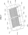
Figure 7 is a perspective view showing a state where both outer leg core parts have different heights; -
Figure 8 is a cross-sectional view showing differences in height and width between the outer leg core parts; and -
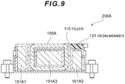
Figure 9 is a cross-sectional view showing a state where a resin member is disposed at a predetermined position to reduce the influence of the difference in height between the outer leg core parts. - Hereinafter, a magnetic coupling reactor apparatus according to the embodiment of the present invention will be explained appropriately using
Figure 1 and other figures. The magnetic coupling reactor apparatus of the present embodiment includes acase 108 made of a material with good heat conductivity such as metal (aluminum or the like) having an upper opening, areactor body 100 stored inside thecase 108, and afiller 110 with insulation properties injected between thecase 108 and thereactor body 100. - Furthermore, in the present embodiment, a case will be particularly explained where an E-shaped core having three leg parts disposed so as to project perpendicularly from a base core part (a yoke part hereinafter simply referred to as a base core part) is used.
- A magnetic
coupling reactor apparatus 200 according to the embodiment of the present invention is configured to be a magnetic coupling type. As shown inFigures 1 and2 , a main part thereof includes a pair ofE-shaped cores E-shaped cores Figure 2 . Furthermore, the middle leg core parts 101A3 and 101B3 are respectively wound withcoils - Furthermore, corner parts of the
E-shaped core 101A are chamfered to form shoulder parts 101C1 and 101C2, and corner parts of theE-shaped core 101B are chamfered to form shoulder parts 101D1 and 101D2. That is, since magnetic fluxes hardly flow through such corner parts, the corner part is chamfered to remove its corner portion, making the entire core compact. - Furthermore, a core member constituting the core part is made of an iron material. Using an iron-based material can achieve high magnetic density and set a high degree of coupling that tends to decrease by the present structure. As an iron-based material, an electromagnetic steel sheet, a powder magnetic core (pure iron, Fe-Si-AL-based alloy, Ni-Fe-Mo-based alloy, or Ni-Fe-based alloy), amorphous, or the like can be used.
- Furthermore, although the tips of the
E-shaped cores - Furthermore, the
coils Figure 1 and the like, the rectangular wire is a belt-shaped flat conductive wire, and one having, for example, a thickness of 0.5 to 6.0 mm and a width of 1.0 to 16.0 mm is typically used. Using the rectangular wire can improve the space factor, achieving size reduction and enhancing the skin effect. Alternatively, one having a different cross-sectional shape such as a round wire or a square wire may be used. - The two
coils coils case 108, respectively fitted to the middle leg core part 101A3 of theE-shaped core 101A and the middle leg core part 101B3 of theE-shaped core 101B, combining with the core part. - That is, when a current flows from one end of the
coil 103A to the other end, and a current flows from one end of thecoil 103B to the other end, the magnetic flux flowing in the middle leg core part 101A3 and the magnetic flux flowing in the middle leg core part 101B3 flow in the opposite directions, so that the magnetic fluxes passing through the two middle leg core parts 101A3 and 101B3 are canceled out. This forms a magnetic flux loop circulating through thecores - The two
coil parts - Furthermore, the middle leg core part 101A3 of the
E-shaped core 101A and the middle leg core part 101B3 of theE-shaped core 101B are respectively provided with thecoil parts - The
E-shaped cores coils cores E-shaped cores bodies body 105A insulates theE-shaped core 101A from thecoil 103A by intervening therebetween, and the resin moldedbody 105B insulates theE-shaped core 101B from thecoil 103B by intervening therebetween. As a resin molding material, for example, unsaturated polyester-based resin, urethane resin, epoxy resin, PBT (polybutylene terephthalate), PPS (polyphenylene sulfide), or the like and the resin molding material to which glass and a heat conductive filler are added can be used. -
Figure 3 is a schematic perspective view of the magnetic coupling reactor apparatus according to the present embodiment. The magneticcoupling reactor apparatus 200 is fixed by a screw to a base part (not shown) on which the magneticcoupling reactor apparatus 200 is mounted. That is, thecase 108 made of metal such as aluminum includesscrew fastening parts 108A on four sides thereof. A screw (not shown) is screwed into the base part via ascrew hole 108B of thescrew fastening part 108A, so that the magneticcoupling reactor apparatus 200 can be mounted on the base part. Although the tips of the above describedE-shaped cores - Furthermore, the
case 108 stores the reactor body in which theE-shaped cores coils E-shaped core 101A from thecoil 103A by intervening therebetween, and the resin molded body (bobbin) 105B can insulate theE-shaped core 101B from thecoil 103B by intervening therebetween. Furthermore, the reactor body is restrained from above so as to be fixed inside thecase 108. The resin molded body (bobbin) is fixed to thecase 108 by abolt 107. - Furthermore, the
case 108 is provided withterminal blocks terminal block 106A supports a metal terminal 103C1 connected to an input end 103A1 of thecoil 103A and a metal terminal 103D1 connected to an input end 103B1 of thecoil 103B. Theterminal block 106B supports a metal terminal 103C2 connected to an output end 103A2 of thecoil 103A and a metal terminal 103D2 connected to an output end 103B2 of thecoil 103B. - Furthermore, the
case 108 is provided with athermistor 109 that measures temperature of the reactor body and thefiller 110 that fills a gap inside thecase 108 to achieve uniform heat distribution. Thefiller 110 can be used by solidifying a liquid or gel material made of, for example, urethane resin, epoxy resin, acrylic resin, silicone resin, or the like and the filler to which a heat conductive filler is added. - By the way, in the present embodiment, the ratio of a cross-sectional area of the middle leg core part 101A3 with respect to the outer leg core parts 101A1 and 101A2 is specified within a predetermined range, increasing the self-inductance and improving the direct current superposition characteristics.
- That is, according to the cross-sectional view of the reactor body as shown in, for example,
Figure 4 , a center part thereof is provided with the middle leg core part 101A3 wound with thecoil part 103A, and both sides of the middle leg core part 101A3 are respectively provided with the outer leg core parts 101A1 and 101A2. - Here, when the cross-sectional area of the middle leg core part 101A3 is Si, and a cross-sectional area of the outer leg core part 101A1 or 101A2 (either one of the cross-sectional areas of the outer leg core parts 101A1 and 101A2) is So, a conditional expression (1) below holds. The cross section here indicates a cross section in a direction orthogonal to an axis of each leg part.

-
Figure 5 is a graph showing changes in inductance (µH) with respect to the value of Si/So (inFigure 5 , described as middle leg cross-sectional area/outer leg cross-sectional area). According toFigure 5 , the value of Si/So is maximized in the vicinity of 2 to 2.5, and when it is less than 1, the value of inductance sharply decreases. - In the present embodiment, the lower limit of Si/So is 1.0, and the upper limit thereof is 5.0. Thus, the inductance can be about 400 µH or more, and the self-inductance can be a relatively large value. Furthermore, the magnetic coupling reactor apparatus can be configured so as to further improve the direct current superposition characteristics.
- Instead of the conditional expression (1), a conditional expression (2) below is further desirable.

- In this way, when the lower limit of Si/So is set to be 1.5 and the upper limit thereof is set to be 3.5, the inductance can be about 450 µH or more, and the self-inductance can be a larger value. Furthermore, the magnetic coupling reactor apparatus can be configured so as to further improve the direct current superposition characteristics.
- Furthermore, instead of the conditional expression (2), a conditional expression (3) below is further desirable.

- In this way, when the lower limit of Si/So is set to be 1.5 and the upper limit thereof is set to be 3.0, the inductance can be 450 µH or more, and the self-inductance can be a larger value. Furthermore, the direct current superposition characteristics can be further improved.
- A core shape in the magnetic coupling reactor apparatus of the present embodiment according to a modified example for promoting reduction in height will be explained using
Figure 6 . - That is, according to the cross-sectional view of the reactor body as shown in
Figure 6 , the center part thereof is provided with the middle leg core part 101A3 wound with thecoil part 103A, and both sides of the middle leg core part 101A3 are respectively provided with the outer leg core parts 101A1 and 101A2. Thefiller 110 is injected between the members. - In this modified example, as shown in
Figure 6 , the input end 103A1 and the output end 103A2 are pulled out from thewound coil 103A in the lateral direction in the figure. The pulled-out input end 103A1 is placed on thebobbin 105A above the outer leg core part 101A2, and the pulled-out output end 103A2 is placed on thebobbin 105A above the outer leg core part 101A1. In this way, the height of thecoil 103A inFigure 6 becomes the smallest when an upper side of the winding part is aligned with the pulled-out input end 103A1 and the pulled-out output end 103A2. - Accordingly, in this modified example, the middle leg core part 101A3 is disposed so as to be offset upward with respect to the outer leg core parts 101A1 and 101A2. The middle leg core part 101A3 thereby fits within a hollow part of the
coil 103A, ensuring reduction in height of the reactor body. - In
Figure 6 , a heatconductive member 111 is disposed between a lower surface of thecoil 103A and a heat sink, which is not shown. Thecoil 103A is placed on the heatconductive member 111. Thereby, a member surface abutting against the heat sink can be flat. This improves heat conduction efficiency with respect to the heat sink, resulting in improved heat dissipation. - The offset amount of the middle leg core part 101A3 is obtained by adding the width of the
coil 103A to the distance for ensuring insulation and α, which is the sum of the assembly margins. - An aspect of the magnetic coupling reactor apparatus of the present embodiment for enhancing the freedom in layout of the terminal part will be explained.
- As shown in
Figure 3 , theterminal block 106A of the magneticcoupling reactor apparatus 200 is provided with end connection parts 103C1 and 103D1. A current from the end connection part 103C1 is input from the input end 103A1 of the coil into thecoil 103A, and a current from the end connection part 103D1 is input from the input end 103B1 of the coil into thecoil 103B. That is, current input ends of the twocoils coils terminal block 106B is provided with the end connection parts 103C2 and 103D2. A current from thecoil 103A is output via the output end 103A2 to the end connection part 103C2, and a current from thecoil 103B is output via the output end 103B2 to the end connection part 103D2. That is, current output ends of the twocoils coils - In this way, the positions of the input ends of the two
coils coils coils coils - This reduces loss in the wiring, enhances the freedom in layout of the terminal part, and achieves reduction in height.
- Furthermore, a core shape in the magnetic coupling reactor apparatus of the present embodiment according to the other modified example for promoting reduction in height will be explained using
Figure 7 . - In the modified example shown in
Figure 7 , similarly to thereactor body 100 of the magneticcoupling reactor apparatus 200 shown inFigure 3 , areactor body 100A includes the pair ofE-shaped cores coils reactor body 100A, an input end 113A1 and output end 113A2 of acoil 113A are all pulled out to one side of thecoil 103A, and an input end 113B1 and output end 113B2 of acoil 113B are all pulled out to one side of thecoil 103B. The height of the outer leg core part 101A2 on the side from which thecoil 103A is pulled out is formed to be lower by the width of thecoil 113A than the heights of the outer leg core part 101A1 on the other side and the base core part 101A4. The height of the outer leg core part 101B2 on the side from which thecoil 103B is pulled out is formed to be lower by the width of thecoil 113B than the heights of the outer leg core part 101B1 on the other side and the base core part 101B4. This enhances the self-inductance and reduces loss in the wiring. - As described above, the cross-sectional areas of the outer leg core parts 101A2 and 101B2 on one side (wiring lead-out side) are desirably formed to be equal to those of the outer leg core parts 101A1 and 101B1 on the other side, respectively. As above, to respectively equalize the cross-sectional areas of the outer leg core parts 101A2 and 101B2 on one side and the outer leg core parts 101A1 and 101B1 on the other side as a result of creating differences in height between the outer leg core part 101A2 and the outer leg core part 101A1 and between the outer leg core part 101B2 and the outer leg core part 101B1, the lateral widths of the outer leg core parts 101A2 and 101B2 on one side (wiring lead-out side) are respectively made longer than those of the outer leg core parts 101A1 and 101B1 on the other side, as shown in a magnetic
coupling reactor apparatus 200A inFigure 8 . That is, when the heights of the outer leg core parts 101A2 and 101B2 are H1 and the lateral widths thereof are W1, and the heights of the outer leg core parts 101A1 and 101B1 are H2 and the lateral widths thereof are W2, the lateral widths W1 and W2 are adjusted so that an equation of H1 × W1 = H2 × W2 holds. This reduces the size of theentire reactor body 100A. - Furthermore, as above, when the heights of the outer leg core parts 101A2 and 101B2 on the side from which the
coils filler 110 filled for a heat dissipation effect may only be filled to the heights of the outer leg core parts 101A2 and 101B2. - Accordingly, as shown in
Figure 9 , aresin member 121 made of a material different from thefiller 110 is disposed at upper regions of the outer leg core parts 101A2 and 101B2 so that the heights of the outer leg core parts 101A2 and 101B2 including theresin member 121 are approximately the same as those of the outer leg core parts 101A1 and 101B1. Thus, thefiller 110 can be filled to the heights of the outer leg core parts 101A1 and 101B1. This improves heat dissipation performance. - The
resin member 121 is desirably a flowable material for facilitating the filling, and more desirably an inexpensive insulative material. Suitable examples of the specific material include phenol resin and PPS (polyphenylene sulfide resin). - In the assembly process of the magnetic coupling reactor apparatus of the present embodiment, the
coil parts E-shaped cores coils coils E-shaped cores - The magnetic coupling reactor apparatus of the present invention is not limited to the above embodiment and can be modified in various ways.
- For example, although in the magnetic coupling reactor apparatus of the above described embodiment, the core part is formed by combining two E-shaped cores whose three leg core parts project from the base core part, the magnetic coupling reactor apparatus of the present invention, not limited to this, can include any number of two or more multi-leg core members whose any number of four or more leg core parts project from the base core part.
- Furthermore, when the multi-leg core member whose four or more leg core parts project from the base core part is used, any of middle leg core parts can be wound. Furthermore, each multi-leg core member can include any polyphase having two or more phases.
- Furthermore, a cross-sectional shape of the multi-leg core member may not be rectangular and may be another shape such as a circle or an ellipse.
- In the above, although one coil is provided for the middle leg core part of each E-shaped core, any number of coils may be provided for the individual middle leg core parts 101A3 and 101B3. Note that it is preferable that a symmetrical form is configured as a whole.
- Furthermore, as described above, the two
coil parts coils coils - A pair of iron-based
E-shaped cores 
Claims (12)
- A magnetic coupling reactor apparatus comprising at least one pair of multi-leg core members made of an iron-based material, the at least one pair of multi-leg core members comprising: a base core part; and three or more leg core parts projecting from the base core part in an identical direction,
wherein the at least one pair of multi-leg core members is disposed so that corresponding leg core parts abut against each other, and at least one coil winding leg core part forming, of the corresponding leg core parts, an inner leg core part except for both outer leg core parts includes an abutting portion of the inner leg core part, a coil part being attached in a winding state to each of the leg core parts sandwiching the abutting portion so as to form a magnetic coupling structure, and
when a cross-sectional area of the coil winding leg core part orthogonal to an extending direction of the coil winding leg core part is Si, and a cross-sectional area of each of the outer leg core parts orthogonal to an extending direction of the outer leg core parts is So, a conditional expression (1) below holds.
- The magnetic coupling reactor apparatus according to claim 1, wherein a range of the conditional expression (1) is limited to a range of a conditional expression (2) below.

- The magnetic coupling reactor apparatus according to claim 1, wherein a range of the conditional expression (1) is limited to a range of a conditional expression (3) below.

- The magnetic coupling reactor apparatus according to any one of claims 1 to 3, wherein
the multi-leg core member is made of an E-shaped core member, and
one coil part is attached to a middle leg core part forming the coil winding leg core part of the E-shaped core member in a winding state. - The magnetic coupling reactor apparatus according to claim 4, wherein the middle leg core part is offset upward at least by a width of the coil part with respect to the outer leg core parts.
- The magnetic coupling reactor apparatus according to claim 4 or 5, wherein a corner part of the E-shaped core member has a chamfer extending in a thickness direction of the E-shaped core member.
- The magnetic coupling reactor apparatus according to claim 5 or 6, wherein an input end of the coil part wound around each of the corresponding coil winding leg core parts of the pair of multi-leg core members is disposed on one side with respect to an axis of the multi-leg core member, and winding directions of the coil parts are reversed to each other.
- The magnetic coupling reactor apparatus according to any one of claims 1 to 7, wherein an input end and output end of each of the coil parts wound around each of the corresponding coil winding leg core parts of the pair of multi-leg core members are pulled out above an upper end surface of the outer leg core part on one side, and a height of the outer leg core part on the one side is set to be lower by a dimension corresponding to a width of the coil part than a height of the outer leg core part on the other side.
- The magnetic coupling reactor apparatus according to any one of claims 1 to 8, wherein an area of a cross section in a direction orthogonal to an axis of the outer leg core part on one side is formed to be equal to an area of a cross section in a direction orthogonal to an axis of the outer leg core part on the other side, and in the two cross sections, the cross section on the one side is formed to be lower in height and wider in width than the cross section on the other side.
- The magnetic coupling reactor apparatus according to any one of claims 1 to 9, wherein a resin material having a thickness corresponding to a difference in height between the outer leg core part on one side and the outer leg core part on the other side is attached to a portion where an input end and output end of each of the coil parts are not disposed on an upper surface of the outer leg core part on the one side.
- The magnetic coupling reactor apparatus according to any one of claims 4 to 10, wherein the middle leg core part is provided with one or more air gaps.
- The magnetic coupling reactor apparatus according to any one of claims 4 to 9, wherein at least one of the outer leg core parts is provided with one or more air gaps.
Applications Claiming Priority (1)
| Application Number | Priority Date | Filing Date | Title |
|---|---|---|---|
| JP2019134174A JP7251377B2 (en) | 2019-07-19 | 2019-07-19 | Magnetically coupled reactor device |
Publications (2)
| Publication Number | Publication Date |
|---|---|
| EP3767652A1 true EP3767652A1 (en) | 2021-01-20 |
| EP3767652B1 EP3767652B1 (en) | 2023-03-22 |
Family
ID=71120038
Family Applications (1)
| Application Number | Title | Priority Date | Filing Date |
|---|---|---|---|
| EP20181317.7A Active EP3767652B1 (en) | 2019-07-19 | 2020-06-22 | Magnetic coupling reactor apparatus |
Country Status (4)
| Country | Link |
|---|---|
| US (1) | US11735351B2 (en) |
| EP (1) | EP3767652B1 (en) |
| JP (1) | JP7251377B2 (en) |
| CN (1) | CN112242233B (en) |
Families Citing this family (7)
| Publication number | Priority date | Publication date | Assignee | Title |
|---|---|---|---|---|
| JP7613880B2 (en) * | 2020-10-23 | 2025-01-15 | 株式会社トーキン | Reactor |
| US12500031B2 (en) * | 2021-11-09 | 2025-12-16 | Cyntec Co., Ltd. | Magnetic component and magnetic body thereof |
| JP7593303B2 (en) * | 2021-11-22 | 2024-12-03 | トヨタ自動車株式会社 | Reactor manufacturing device and manufacturing method |
| JP2026511765A (en) * | 2023-03-29 | 2026-04-14 | エルジー イノテック カンパニー リミテッド | Power converter |
| JP7605885B2 (en) | 2023-03-30 | 2024-12-24 | 本田技研工業株式会社 | Inductors |
| JP2024171665A (en) * | 2023-05-30 | 2024-12-12 | 株式会社オートネットワーク技術研究所 | Reactor, converter and power conversion device |
| KR20250145931A (en) * | 2024-03-29 | 2025-10-13 | 엘지이노텍 주식회사 | Magnetic component |
Citations (7)
| Publication number | Priority date | Publication date | Assignee | Title |
|---|---|---|---|---|
| JPS616646B2 (en) | 1979-01-11 | 1986-02-28 | Fuooruberuku Unto Co Intahorudeingu Gmbh | |
| JPH03150810A (en) * | 1989-11-07 | 1991-06-27 | Matsushita Electric Ind Co Ltd | line filter |
| EP1879200A1 (en) * | 2006-07-10 | 2008-01-16 | Rockwell Automation Technologies, Inc. | Methods and apparatus for flux dispersal in link inductor |
| US20150325354A1 (en) * | 2014-05-09 | 2015-11-12 | Sumida Corporation | Inductor and method of manufacturing inductor |
| JP2016066751A (en) * | 2014-09-25 | 2016-04-28 | 株式会社タムラ製作所 | Reactor |
| JP2018026467A (en) * | 2016-08-10 | 2018-02-15 | 株式会社タムラ製作所 | Reactor |
| JP2018133499A (en) * | 2017-02-16 | 2018-08-23 | スミダコーポレーション株式会社 | Reactor and manufacturing method thereof |
Family Cites Families (39)
| Publication number | Priority date | Publication date | Assignee | Title |
|---|---|---|---|---|
| US2485599A (en) * | 1945-04-09 | 1949-10-25 | Standard Telephones Cables Ltd | Magnetic core and clamp |
| US3332049A (en) * | 1965-11-30 | 1967-07-18 | Tdk Electronics Co Ltd | Magnetic core unit with shielded winding |
| JPS616646U (en) * | 1984-06-19 | 1986-01-16 | 株式会社 日本気化器製作所 | Removable doss pot |
| JPH0528745Y2 (en) * | 1985-02-27 | 1993-07-23 | ||
| JPH0837113A (en) * | 1994-07-25 | 1996-02-06 | Nemic Lambda Kk | Core |
| JPH0945550A (en) * | 1995-07-27 | 1997-02-14 | Tokin Corp | High frequency transformer |
| JP2000216033A (en) * | 1999-01-27 | 2000-08-04 | Tokin Corp | Common mode choke coil |
| US6927667B1 (en) * | 2001-11-01 | 2005-08-09 | Tyco Electronics Power Systems, Inc. | Magnetic device having a springable winding |
| US20050278940A1 (en) * | 2002-07-02 | 2005-12-22 | Taiwan Thick-Film Ind. Corp. | Method for winding transformers |
| JP2004335886A (en) * | 2003-05-09 | 2004-11-25 | Canon Inc | Transformer assembly, power conversion device and solar power generation device using the same |
| JP2005109384A (en) * | 2003-10-02 | 2005-04-21 | Matsushita Electric Ind Co Ltd | Reactor |
| KR100726262B1 (en) * | 2004-08-05 | 2007-06-08 | 스미다 코포레이션 | Magnetic elements |
| US20070057756A1 (en) * | 2005-09-12 | 2007-03-15 | Sen-Tai Yang | Structure of inductance core |
| US8060218B2 (en) * | 2007-08-02 | 2011-11-15 | Synecor, Llc | Inductive element for intravascular implantable devices |
| JP6079225B2 (en) * | 2012-12-27 | 2017-02-15 | Fdk株式会社 | Trance |
| JP5997111B2 (en) * | 2013-08-04 | 2016-09-28 | 株式会社タムラ製作所 | Resin mold core and reactor using it |
| JP5940504B2 (en) * | 2013-10-11 | 2016-06-29 | スミダコーポレーション株式会社 | Coil parts |
| JP2015115434A (en) | 2013-12-11 | 2015-06-22 | 株式会社豊田中央研究所 | Magnetically coupled inductors and multiport converters |
| DE102014206469A1 (en) * | 2014-04-03 | 2015-10-08 | SUMIDA Components & Modules GmbH | THROTTLE AND THROTTLE CORE |
| TWI493579B (en) * | 2014-04-16 | 2015-07-21 | Delta Electronics Inc | Magnetic element with multi-gaps |
| US9355770B2 (en) * | 2014-04-22 | 2016-05-31 | Transformers, LLC | Transformer with improved power handling capacity |
| JP6490355B2 (en) | 2014-06-24 | 2019-03-27 | 株式会社タムラ製作所 | Reactor parts and reactors |
| US9799442B1 (en) * | 2014-08-18 | 2017-10-24 | Universal Lighting Technologies, Inc. | Magnetic core structures for magnetic assemblies |
| US9666355B1 (en) * | 2014-08-18 | 2017-05-30 | Universale Lighting Technologies, Inc. | Common mode inductor assembly with magnetic I bar defined leakage path |
| US9633778B2 (en) * | 2014-11-21 | 2017-04-25 | Hamilton Sundstrand Corporation | Magnetic component with balanced flux distribution |
| JP2017050334A (en) | 2015-08-31 | 2017-03-09 | トヨタ自動車株式会社 | Reactor |
| US9837194B1 (en) * | 2015-10-07 | 2017-12-05 | Universal Lighting Technologies, Inc. | Output transformer and resonant inductor in a combined magnetic structure |
| CN205282221U (en) * | 2015-12-08 | 2016-06-01 | 光宝电子(广州)有限公司 | Transformer bearing and use electron device of this transformer bearing |
| JP2017199890A (en) * | 2016-04-26 | 2017-11-02 | 株式会社オートネットワーク技術研究所 | Reactor |
| JP6674872B2 (en) * | 2016-09-09 | 2020-04-01 | 株式会社タムラ製作所 | Reactor and manufacturing method |
| JP6811604B2 (en) * | 2016-12-27 | 2021-01-13 | 株式会社タムラ製作所 | Reactor |
| JP6610903B2 (en) | 2017-02-10 | 2019-11-27 | 株式会社オートネットワーク技術研究所 | Reactor |
| JP2018133500A (en) * | 2017-02-16 | 2018-08-23 | スミダコーポレーション株式会社 | Reactor and manufacturing method thereof |
| JP6677204B2 (en) * | 2017-03-28 | 2020-04-08 | トヨタ自動車株式会社 | Reactor manufacturing method and heating device |
| JP6930177B2 (en) * | 2017-03-30 | 2021-09-01 | スミダコーポレーション株式会社 | Transformers and transformer manufacturing methods |
| US20180301276A1 (en) * | 2017-04-18 | 2018-10-18 | MAG.LAYERS Scientific-Technics Co., Ltd. | Multiple winding inductor assembly |
| EP3410447A1 (en) * | 2017-06-01 | 2018-12-05 | Solaredge Technologies Ltd. | Distributed gap for magnetic cores |
| US11322298B2 (en) * | 2017-09-15 | 2022-05-03 | University Of Florida Research Foundation, Incorporated | Integrated common mode and differential mode inductors with low near magnetic field emission |
| TWI630628B (en) * | 2017-10-19 | 2018-07-21 | 光壽科技有限公司 | Capacitive resistance voltage conversion device |
-
2019
- 2019-07-19 JP JP2019134174A patent/JP7251377B2/en active Active
-
2020
- 2020-06-22 EP EP20181317.7A patent/EP3767652B1/en active Active
- 2020-07-06 CN CN202010643387.8A patent/CN112242233B/en active Active
- 2020-07-09 US US16/924,687 patent/US11735351B2/en active Active
Patent Citations (7)
| Publication number | Priority date | Publication date | Assignee | Title |
|---|---|---|---|---|
| JPS616646B2 (en) | 1979-01-11 | 1986-02-28 | Fuooruberuku Unto Co Intahorudeingu Gmbh | |
| JPH03150810A (en) * | 1989-11-07 | 1991-06-27 | Matsushita Electric Ind Co Ltd | line filter |
| EP1879200A1 (en) * | 2006-07-10 | 2008-01-16 | Rockwell Automation Technologies, Inc. | Methods and apparatus for flux dispersal in link inductor |
| US20150325354A1 (en) * | 2014-05-09 | 2015-11-12 | Sumida Corporation | Inductor and method of manufacturing inductor |
| JP2016066751A (en) * | 2014-09-25 | 2016-04-28 | 株式会社タムラ製作所 | Reactor |
| JP2018026467A (en) * | 2016-08-10 | 2018-02-15 | 株式会社タムラ製作所 | Reactor |
| JP2018133499A (en) * | 2017-02-16 | 2018-08-23 | スミダコーポレーション株式会社 | Reactor and manufacturing method thereof |
Also Published As
| Publication number | Publication date |
|---|---|
| US20210020351A1 (en) | 2021-01-21 |
| EP3767652B1 (en) | 2023-03-22 |
| CN112242233A (en) | 2021-01-19 |
| CN112242233B (en) | 2025-08-08 |
| US11735351B2 (en) | 2023-08-22 |
| JP7251377B2 (en) | 2023-04-04 |
| JP2021019103A (en) | 2021-02-15 |
Similar Documents
| Publication | Publication Date | Title |
|---|---|---|
| EP3767652B1 (en) | Magnetic coupling reactor apparatus | |
| US20120206232A1 (en) | Reactor | |
| US8686820B2 (en) | Reactor | |
| US9440542B2 (en) | Reactor, converter, and power conversion device | |
| CN102971813B (en) | Reactor | |
| US12266462B2 (en) | Reactor and multi-phase interleave-type DC-DC converter | |
| US20170278606A1 (en) | Magnetic circuit component | |
| US20210407725A1 (en) | Reactor | |
| JP2011142193A (en) | Reactor | |
| JP6635316B2 (en) | Reactor | |
| US12394554B2 (en) | Low profile high current coupled winding electromagnetic component | |
| JP2011124245A (en) | Reactor device | |
| JP2011124242A (en) | Reactor device | |
| JP2013157352A (en) | Coil device | |
| JP2023167200A (en) | LLC resonant circuit transformer device | |
| JP5140065B2 (en) | Reactor | |
| JP2022045166A (en) | Reactors, converters, and power converters | |
| US20240363279A1 (en) | Reactor, converter and power conversion device | |
| JP2017034102A (en) | Reactor | |
| US20240355526A1 (en) | Reactor, converter, and power conversion device | |
| JP2021019104A (en) | Reactor device | |
| US20190214186A1 (en) | Coil, reactor, and coil design method | |
| JP2024171665A (en) | Reactor, converter and power conversion device | |
| US20230307169A1 (en) | Reactor, converter, and power conversion device | |
| JP6809439B2 (en) | Reactor |
Legal Events
| Date | Code | Title | Description |
|---|---|---|---|
| PUAI | Public reference made under article 153(3) epc to a published international application that has entered the european phase |
Free format text: ORIGINAL CODE: 0009012 |
|
| STAA | Information on the status of an ep patent application or granted ep patent |
Free format text: STATUS: THE APPLICATION HAS BEEN PUBLISHED |
|
| AK | Designated contracting states |
Kind code of ref document: A1 Designated state(s): AL AT BE BG CH CY CZ DE DK EE ES FI FR GB GR HR HU IE IS IT LI LT LU LV MC MK MT NL NO PL PT RO RS SE SI SK SM TR |
|
| AX | Request for extension of the european patent |
Extension state: BA ME |
|
| STAA | Information on the status of an ep patent application or granted ep patent |
Free format text: STATUS: REQUEST FOR EXAMINATION WAS MADE |
|
| RAP3 | Party data changed (applicant data changed or rights of an application transferred) |
Owner name: SUMIDA CORPORATION |
|
| 17P | Request for examination filed |
Effective date: 20210511 |
|
| RBV | Designated contracting states (corrected) |
Designated state(s): AL AT BE BG CH CY CZ DE DK EE ES FI FR GB GR HR HU IE IS IT LI LT LU LV MC MK MT NL NO PL PT RO RS SE SI SK SM TR |
|
| GRAP | Despatch of communication of intention to grant a patent |
Free format text: ORIGINAL CODE: EPIDOSNIGR1 |
|
| STAA | Information on the status of an ep patent application or granted ep patent |
Free format text: STATUS: GRANT OF PATENT IS INTENDED |
|
| INTG | Intention to grant announced |
Effective date: 20221129 |
|
| GRAS | Grant fee paid |
Free format text: ORIGINAL CODE: EPIDOSNIGR3 |
|
| GRAA | (expected) grant |
Free format text: ORIGINAL CODE: 0009210 |
|
| STAA | Information on the status of an ep patent application or granted ep patent |
Free format text: STATUS: THE PATENT HAS BEEN GRANTED |
|
| RAP3 | Party data changed (applicant data changed or rights of an application transferred) |
Owner name: SUMIDA CORPORATION |
|
| AK | Designated contracting states |
Kind code of ref document: B1 Designated state(s): AL AT BE BG CH CY CZ DE DK EE ES FI FR GB GR HR HU IE IS IT LI LT LU LV MC MK MT NL NO PL PT RO RS SE SI SK SM TR |
|
| REG | Reference to a national code |
Ref country code: GB Ref legal event code: FG4D |
|
| REG | Reference to a national code |
Ref country code: CH Ref legal event code: EP |
|
| REG | Reference to a national code |
Ref country code: IE Ref legal event code: FG4D |
|
| REG | Reference to a national code |
Ref country code: DE Ref legal event code: R096 Ref document number: 602020008966 Country of ref document: DE |
|
| REG | Reference to a national code |
Ref country code: AT Ref legal event code: REF Ref document number: 1555801 Country of ref document: AT Kind code of ref document: T Effective date: 20230415 |
|
| REG | Reference to a national code |
Ref country code: LT Ref legal event code: MG9D |
|
| REG | Reference to a national code |
Ref country code: NL Ref legal event code: MP Effective date: 20230322 |
|
| PG25 | Lapsed in a contracting state [announced via postgrant information from national office to epo] |
Ref country code: RS Free format text: LAPSE BECAUSE OF FAILURE TO SUBMIT A TRANSLATION OF THE DESCRIPTION OR TO PAY THE FEE WITHIN THE PRESCRIBED TIME-LIMIT Effective date: 20230322 Ref country code: NO Free format text: LAPSE BECAUSE OF FAILURE TO SUBMIT A TRANSLATION OF THE DESCRIPTION OR TO PAY THE FEE WITHIN THE PRESCRIBED TIME-LIMIT Effective date: 20230622 Ref country code: LV Free format text: LAPSE BECAUSE OF FAILURE TO SUBMIT A TRANSLATION OF THE DESCRIPTION OR TO PAY THE FEE WITHIN THE PRESCRIBED TIME-LIMIT Effective date: 20230322 Ref country code: LT Free format text: LAPSE BECAUSE OF FAILURE TO SUBMIT A TRANSLATION OF THE DESCRIPTION OR TO PAY THE FEE WITHIN THE PRESCRIBED TIME-LIMIT Effective date: 20230322 Ref country code: HR Free format text: LAPSE BECAUSE OF FAILURE TO SUBMIT A TRANSLATION OF THE DESCRIPTION OR TO PAY THE FEE WITHIN THE PRESCRIBED TIME-LIMIT Effective date: 20230322 |
|
| REG | Reference to a national code |
Ref country code: AT Ref legal event code: MK05 Ref document number: 1555801 Country of ref document: AT Kind code of ref document: T Effective date: 20230322 |
|
| PG25 | Lapsed in a contracting state [announced via postgrant information from national office to epo] |
Ref country code: SE Free format text: LAPSE BECAUSE OF FAILURE TO SUBMIT A TRANSLATION OF THE DESCRIPTION OR TO PAY THE FEE WITHIN THE PRESCRIBED TIME-LIMIT Effective date: 20230322 Ref country code: NL Free format text: LAPSE BECAUSE OF FAILURE TO SUBMIT A TRANSLATION OF THE DESCRIPTION OR TO PAY THE FEE WITHIN THE PRESCRIBED TIME-LIMIT Effective date: 20230322 Ref country code: GR Free format text: LAPSE BECAUSE OF FAILURE TO SUBMIT A TRANSLATION OF THE DESCRIPTION OR TO PAY THE FEE WITHIN THE PRESCRIBED TIME-LIMIT Effective date: 20230623 Ref country code: FI Free format text: LAPSE BECAUSE OF FAILURE TO SUBMIT A TRANSLATION OF THE DESCRIPTION OR TO PAY THE FEE WITHIN THE PRESCRIBED TIME-LIMIT Effective date: 20230322 |
|
| PG25 | Lapsed in a contracting state [announced via postgrant information from national office to epo] |
Ref country code: SM Free format text: LAPSE BECAUSE OF FAILURE TO SUBMIT A TRANSLATION OF THE DESCRIPTION OR TO PAY THE FEE WITHIN THE PRESCRIBED TIME-LIMIT Effective date: 20230322 Ref country code: RO Free format text: LAPSE BECAUSE OF FAILURE TO SUBMIT A TRANSLATION OF THE DESCRIPTION OR TO PAY THE FEE WITHIN THE PRESCRIBED TIME-LIMIT Effective date: 20230322 Ref country code: PT Free format text: LAPSE BECAUSE OF FAILURE TO SUBMIT A TRANSLATION OF THE DESCRIPTION OR TO PAY THE FEE WITHIN THE PRESCRIBED TIME-LIMIT Effective date: 20230724 Ref country code: ES Free format text: LAPSE BECAUSE OF FAILURE TO SUBMIT A TRANSLATION OF THE DESCRIPTION OR TO PAY THE FEE WITHIN THE PRESCRIBED TIME-LIMIT Effective date: 20230322 Ref country code: EE Free format text: LAPSE BECAUSE OF FAILURE TO SUBMIT A TRANSLATION OF THE DESCRIPTION OR TO PAY THE FEE WITHIN THE PRESCRIBED TIME-LIMIT Effective date: 20230322 Ref country code: AT Free format text: LAPSE BECAUSE OF FAILURE TO SUBMIT A TRANSLATION OF THE DESCRIPTION OR TO PAY THE FEE WITHIN THE PRESCRIBED TIME-LIMIT Effective date: 20230322 |
|
| PG25 | Lapsed in a contracting state [announced via postgrant information from national office to epo] |
Ref country code: SK Free format text: LAPSE BECAUSE OF FAILURE TO SUBMIT A TRANSLATION OF THE DESCRIPTION OR TO PAY THE FEE WITHIN THE PRESCRIBED TIME-LIMIT Effective date: 20230322 Ref country code: PL Free format text: LAPSE BECAUSE OF FAILURE TO SUBMIT A TRANSLATION OF THE DESCRIPTION OR TO PAY THE FEE WITHIN THE PRESCRIBED TIME-LIMIT Effective date: 20230322 Ref country code: IS Free format text: LAPSE BECAUSE OF FAILURE TO SUBMIT A TRANSLATION OF THE DESCRIPTION OR TO PAY THE FEE WITHIN THE PRESCRIBED TIME-LIMIT Effective date: 20230722 |
|
| REG | Reference to a national code |
Ref country code: DE Ref legal event code: R097 Ref document number: 602020008966 Country of ref document: DE |
|
| PG25 | Lapsed in a contracting state [announced via postgrant information from national office to epo] |
Ref country code: MC Free format text: LAPSE BECAUSE OF FAILURE TO SUBMIT A TRANSLATION OF THE DESCRIPTION OR TO PAY THE FEE WITHIN THE PRESCRIBED TIME-LIMIT Effective date: 20230322 |
|
| PLBE | No opposition filed within time limit |
Free format text: ORIGINAL CODE: 0009261 |
|
| STAA | Information on the status of an ep patent application or granted ep patent |
Free format text: STATUS: NO OPPOSITION FILED WITHIN TIME LIMIT |
|
| PG25 | Lapsed in a contracting state [announced via postgrant information from national office to epo] |
Ref country code: SI Free format text: LAPSE BECAUSE OF FAILURE TO SUBMIT A TRANSLATION OF THE DESCRIPTION OR TO PAY THE FEE WITHIN THE PRESCRIBED TIME-LIMIT Effective date: 20230322 Ref country code: MC Free format text: LAPSE BECAUSE OF FAILURE TO SUBMIT A TRANSLATION OF THE DESCRIPTION OR TO PAY THE FEE WITHIN THE PRESCRIBED TIME-LIMIT Effective date: 20230322 Ref country code: DK Free format text: LAPSE BECAUSE OF FAILURE TO SUBMIT A TRANSLATION OF THE DESCRIPTION OR TO PAY THE FEE WITHIN THE PRESCRIBED TIME-LIMIT Effective date: 20230322 Ref country code: CZ Free format text: LAPSE BECAUSE OF FAILURE TO SUBMIT A TRANSLATION OF THE DESCRIPTION OR TO PAY THE FEE WITHIN THE PRESCRIBED TIME-LIMIT Effective date: 20230322 |
|
| REG | Reference to a national code |
Ref country code: CH Ref legal event code: PL |
|
| REG | Reference to a national code |
Ref country code: BE Ref legal event code: MM Effective date: 20230630 |
|
| 26N | No opposition filed |
Effective date: 20240102 |
|
| PG25 | Lapsed in a contracting state [announced via postgrant information from national office to epo] |
Ref country code: LU Free format text: LAPSE BECAUSE OF NON-PAYMENT OF DUE FEES Effective date: 20230622 |
|
| REG | Reference to a national code |
Ref country code: IE Ref legal event code: MM4A |
|
| PG25 | Lapsed in a contracting state [announced via postgrant information from national office to epo] |
Ref country code: LU Free format text: LAPSE BECAUSE OF NON-PAYMENT OF DUE FEES Effective date: 20230622 |
|
| PG25 | Lapsed in a contracting state [announced via postgrant information from national office to epo] |
Ref country code: IE Free format text: LAPSE BECAUSE OF NON-PAYMENT OF DUE FEES Effective date: 20230622 |
|
| PG25 | Lapsed in a contracting state [announced via postgrant information from national office to epo] |
Ref country code: IE Free format text: LAPSE BECAUSE OF NON-PAYMENT OF DUE FEES Effective date: 20230622 Ref country code: CH Free format text: LAPSE BECAUSE OF NON-PAYMENT OF DUE FEES Effective date: 20230630 |
|
| PG25 | Lapsed in a contracting state [announced via postgrant information from national office to epo] |
Ref country code: IT Free format text: LAPSE BECAUSE OF FAILURE TO SUBMIT A TRANSLATION OF THE DESCRIPTION OR TO PAY THE FEE WITHIN THE PRESCRIBED TIME-LIMIT Effective date: 20230322 Ref country code: BE Free format text: LAPSE BECAUSE OF NON-PAYMENT OF DUE FEES Effective date: 20230630 |
|
| PG25 | Lapsed in a contracting state [announced via postgrant information from national office to epo] |
Ref country code: BG Free format text: LAPSE BECAUSE OF FAILURE TO SUBMIT A TRANSLATION OF THE DESCRIPTION OR TO PAY THE FEE WITHIN THE PRESCRIBED TIME-LIMIT Effective date: 20230322 |
|
| PG25 | Lapsed in a contracting state [announced via postgrant information from national office to epo] |
Ref country code: BG Free format text: LAPSE BECAUSE OF FAILURE TO SUBMIT A TRANSLATION OF THE DESCRIPTION OR TO PAY THE FEE WITHIN THE PRESCRIBED TIME-LIMIT Effective date: 20230322 |
|
| PGFP | Annual fee paid to national office [announced via postgrant information from national office to epo] |
Ref country code: DE Payment date: 20250618 Year of fee payment: 6 |
|
| PGFP | Annual fee paid to national office [announced via postgrant information from national office to epo] |
Ref country code: GB Payment date: 20250618 Year of fee payment: 6 |
|
| PGFP | Annual fee paid to national office [announced via postgrant information from national office to epo] |
Ref country code: FR Payment date: 20250626 Year of fee payment: 6 |
|
| PG25 | Lapsed in a contracting state [announced via postgrant information from national office to epo] |
Ref country code: CY Free format text: LAPSE BECAUSE OF FAILURE TO SUBMIT A TRANSLATION OF THE DESCRIPTION OR TO PAY THE FEE WITHIN THE PRESCRIBED TIME-LIMIT; INVALID AB INITIO Effective date: 20200622 |
|
| PG25 | Lapsed in a contracting state [announced via postgrant information from national office to epo] |
Ref country code: HU Free format text: LAPSE BECAUSE OF FAILURE TO SUBMIT A TRANSLATION OF THE DESCRIPTION OR TO PAY THE FEE WITHIN THE PRESCRIBED TIME-LIMIT; INVALID AB INITIO Effective date: 20200622 |
|
| PG25 | Lapsed in a contracting state [announced via postgrant information from national office to epo] |
Ref country code: TR Free format text: LAPSE BECAUSE OF FAILURE TO SUBMIT A TRANSLATION OF THE DESCRIPTION OR TO PAY THE FEE WITHIN THE PRESCRIBED TIME-LIMIT Effective date: 20230322 |