EP3767332A1 - Methods and systems for radar object detection - Google Patents
Methods and systems for radar object detection Download PDFInfo
- Publication number
- EP3767332A1 EP3767332A1 EP19187019.5A EP19187019A EP3767332A1 EP 3767332 A1 EP3767332 A1 EP 3767332A1 EP 19187019 A EP19187019 A EP 19187019A EP 3767332 A1 EP3767332 A1 EP 3767332A1
- Authority
- EP
- European Patent Office
- Prior art keywords
- dimension
- map
- tensor
- radar
- grid
- Prior art date
- Legal status (The legal status is an assumption and is not a legal conclusion. Google has not performed a legal analysis and makes no representation as to the accuracy of the status listed.)
- Granted
Links
Images




Classifications
-
- G—PHYSICS
- G01—MEASURING; TESTING
- G01S—RADIO DIRECTION-FINDING; RADIO NAVIGATION; DETERMINING DISTANCE OR VELOCITY BY USE OF RADIO WAVES; LOCATING OR PRESENCE-DETECTING BY USE OF THE REFLECTION OR RERADIATION OF RADIO WAVES; ANALOGOUS ARRANGEMENTS USING OTHER WAVES
- G01S13/00—Systems using the reflection or reradiation of radio waves, e.g. radar systems; Analogous systems using reflection or reradiation of waves whose nature or wavelength is irrelevant or unspecified
- G01S13/66—Radar-tracking systems; Analogous systems
- G01S13/72—Radar-tracking systems; Analogous systems for two-dimensional [2D] tracking, e.g. combination of angle and range tracking, track-while-scan radar
- G01S13/723—Radar-tracking systems; Analogous systems for two-dimensional [2D] tracking, e.g. combination of angle and range tracking, track-while-scan radar by using numerical data
- G01S13/726—Multiple target tracking
-
- G—PHYSICS
- G01—MEASURING; TESTING
- G01S—RADIO DIRECTION-FINDING; RADIO NAVIGATION; DETERMINING DISTANCE OR VELOCITY BY USE OF RADIO WAVES; LOCATING OR PRESENCE-DETECTING BY USE OF THE REFLECTION OR RERADIATION OF RADIO WAVES; ANALOGOUS ARRANGEMENTS USING OTHER WAVES
- G01S13/00—Systems using the reflection or reradiation of radio waves, e.g. radar systems; Analogous systems using reflection or reradiation of waves whose nature or wavelength is irrelevant or unspecified
- G01S13/87—Combinations of radar systems, e.g. primary radar and secondary radar
-
- G—PHYSICS
- G01—MEASURING; TESTING
- G01S—RADIO DIRECTION-FINDING; RADIO NAVIGATION; DETERMINING DISTANCE OR VELOCITY BY USE OF RADIO WAVES; LOCATING OR PRESENCE-DETECTING BY USE OF THE REFLECTION OR RERADIATION OF RADIO WAVES; ANALOGOUS ARRANGEMENTS USING OTHER WAVES
- G01S13/00—Systems using the reflection or reradiation of radio waves, e.g. radar systems; Analogous systems using reflection or reradiation of waves whose nature or wavelength is irrelevant or unspecified
- G01S13/88—Radar or analogous systems specially adapted for specific applications
- G01S13/89—Radar or analogous systems specially adapted for specific applications for mapping or imaging
-
- G—PHYSICS
- G01—MEASURING; TESTING
- G01S—RADIO DIRECTION-FINDING; RADIO NAVIGATION; DETERMINING DISTANCE OR VELOCITY BY USE OF RADIO WAVES; LOCATING OR PRESENCE-DETECTING BY USE OF THE REFLECTION OR RERADIATION OF RADIO WAVES; ANALOGOUS ARRANGEMENTS USING OTHER WAVES
- G01S13/00—Systems using the reflection or reradiation of radio waves, e.g. radar systems; Analogous systems using reflection or reradiation of waves whose nature or wavelength is irrelevant or unspecified
- G01S13/88—Radar or analogous systems specially adapted for specific applications
- G01S13/93—Radar or analogous systems specially adapted for specific applications for anti-collision purposes
- G01S13/931—Radar or analogous systems specially adapted for specific applications for anti-collision purposes of land vehicles
-
- G—PHYSICS
- G01—MEASURING; TESTING
- G01S—RADIO DIRECTION-FINDING; RADIO NAVIGATION; DETERMINING DISTANCE OR VELOCITY BY USE OF RADIO WAVES; LOCATING OR PRESENCE-DETECTING BY USE OF THE REFLECTION OR RERADIATION OF RADIO WAVES; ANALOGOUS ARRANGEMENTS USING OTHER WAVES
- G01S7/00—Details of systems according to groups G01S13/00, G01S15/00, G01S17/00
- G01S7/02—Details of systems according to groups G01S13/00, G01S15/00, G01S17/00 of systems according to group G01S13/00
- G01S7/41—Details of systems according to groups G01S13/00, G01S15/00, G01S17/00 of systems according to group G01S13/00 using analysis of echo signal for target characterisation; Target signature; Target cross-section
- G01S7/417—Details of systems according to groups G01S13/00, G01S15/00, G01S17/00 of systems according to group G01S13/00 using analysis of echo signal for target characterisation; Target signature; Target cross-section involving the use of neural networks
-
- G—PHYSICS
- G06—COMPUTING OR CALCULATING; COUNTING
- G06N—COMPUTING ARRANGEMENTS BASED ON SPECIFIC COMPUTATIONAL MODELS
- G06N3/00—Computing arrangements based on biological models
- G06N3/02—Neural networks
- G06N3/04—Architecture, e.g. interconnection topology
- G06N3/045—Combinations of networks
-
- G—PHYSICS
- G06—COMPUTING OR CALCULATING; COUNTING
- G06N—COMPUTING ARRANGEMENTS BASED ON SPECIFIC COMPUTATIONAL MODELS
- G06N3/00—Computing arrangements based on biological models
- G06N3/02—Neural networks
- G06N3/04—Architecture, e.g. interconnection topology
- G06N3/049—Temporal neural networks, e.g. delay elements, oscillating neurons or pulsed inputs
-
- G—PHYSICS
- G01—MEASURING; TESTING
- G01S—RADIO DIRECTION-FINDING; RADIO NAVIGATION; DETERMINING DISTANCE OR VELOCITY BY USE OF RADIO WAVES; LOCATING OR PRESENCE-DETECTING BY USE OF THE REFLECTION OR RERADIATION OF RADIO WAVES; ANALOGOUS ARRANGEMENTS USING OTHER WAVES
- G01S13/00—Systems using the reflection or reradiation of radio waves, e.g. radar systems; Analogous systems using reflection or reradiation of waves whose nature or wavelength is irrelevant or unspecified
- G01S13/88—Radar or analogous systems specially adapted for specific applications
- G01S13/93—Radar or analogous systems specially adapted for specific applications for anti-collision purposes
- G01S13/931—Radar or analogous systems specially adapted for specific applications for anti-collision purposes of land vehicles
- G01S2013/932—Radar or analogous systems specially adapted for specific applications for anti-collision purposes of land vehicles using own vehicle data, e.g. ground speed, steering wheel direction
-
- G—PHYSICS
- G01—MEASURING; TESTING
- G01S—RADIO DIRECTION-FINDING; RADIO NAVIGATION; DETERMINING DISTANCE OR VELOCITY BY USE OF RADIO WAVES; LOCATING OR PRESENCE-DETECTING BY USE OF THE REFLECTION OR RERADIATION OF RADIO WAVES; ANALOGOUS ARRANGEMENTS USING OTHER WAVES
- G01S7/00—Details of systems according to groups G01S13/00, G01S15/00, G01S17/00
- G01S7/02—Details of systems according to groups G01S13/00, G01S15/00, G01S17/00 of systems according to group G01S13/00
- G01S7/41—Details of systems according to groups G01S13/00, G01S15/00, G01S17/00 of systems according to group G01S13/00 using analysis of echo signal for target characterisation; Target signature; Target cross-section
- G01S7/411—Identification of targets based on measurements of radar reflectivity
-
- G—PHYSICS
- G01—MEASURING; TESTING
- G01S—RADIO DIRECTION-FINDING; RADIO NAVIGATION; DETERMINING DISTANCE OR VELOCITY BY USE OF RADIO WAVES; LOCATING OR PRESENCE-DETECTING BY USE OF THE REFLECTION OR RERADIATION OF RADIO WAVES; ANALOGOUS ARRANGEMENTS USING OTHER WAVES
- G01S7/00—Details of systems according to groups G01S13/00, G01S15/00, G01S17/00
- G01S7/02—Details of systems according to groups G01S13/00, G01S15/00, G01S17/00 of systems according to group G01S13/00
- G01S7/41—Details of systems according to groups G01S13/00, G01S15/00, G01S17/00 of systems according to group G01S13/00 using analysis of echo signal for target characterisation; Target signature; Target cross-section
- G01S7/415—Identification of targets based on measurements of movement associated with the target
-
- H—ELECTRICITY
- H03—ELECTRONIC CIRCUITRY
- H03M—CODING; DECODING; CODE CONVERSION IN GENERAL
- H03M7/00—Conversion of a code where information is represented by a given sequence or number of digits to a code where the same, similar or subset of information is represented by a different sequence or number of digits
- H03M7/30—Compression; Expansion; Suppression of unnecessary data, e.g. redundancy reduction
- H03M7/3059—Digital compression and data reduction techniques where the original information is represented by a subset or similar information, e.g. lossy compression
Definitions
- the present disclosure relates to methods and systems for object detection. Radar detection data and radar map data may be combined and reduced in dimension to provide efficient object detection.
- Radar is a commonly used sensor in automotive perception systems due to its low cost compared with LiDAR and high adaptability to environment changes (e.g. weather or lighting condition) compared with cameras.
- Radar data is usually given in the form of point clouds. Each point is characterized by some features, e.g. its RCS (Radar Cross-Section), range rate (Doppler velocity) and spatial location.
- RCS Radar Cross-Section
- Doppler velocity range rate
- spatial location e.g. its RCS (Radar Cross-Section)
- object detection for example predicting the location and/ or motion of objects and/ or carrying out semantic segmentation for determining a semantic label of every location).
- the present disclosure provides a computer implemented method, a computer system and a non-transitory computer readable medium according to the independent claims. Embodiments are given in the subclaims, the description and the drawings.
- the present disclosure is directed at a computer implemented method for object detection, the method comprising the following steps carried out by computer hardware components: determining a grid, the grid comprising a plurality of grid cells; determining, for a plurality of time steps, for each grid cell, a plurality of respective radar detection data, each radar detection data indicating a plurality of radar properties; determining, for each time step, a respective radar map indicating a pre-determined radar map property in each grid cell; converting the respective radar detection data of the plurality of grid cells for the plurality of time steps to a point representation of pre-determined first dimensions; converting the radar maps for the plurality of time steps to a map representation of pre-determined second dimensions, wherein the pre-determined first dimensions and the pre-determined second dimensions are at least partially identical; concatenating the point representation and the map representation to obtain concatenated data; and carrying out object detection based on the concatenated data.
- radar detection data (which may also be referred to as point-cloud data) and map data may be brought into respective representations which are of dimensions which are suitable for concatenating the representations.
- the representations may be tensors, which have dimensions that match in all but one dimension. Concatenating these tensors may then lead to a tensor in which only the dimension, in which the tensors do not match, is changed (for example to the sum of the respective dimension of the tensors), while the dimensions in which the tensors match remains unchanged.
- combining (for example concatenating) radar detection data and map data into combined (for example concatenated) data may improve detection results when using the combined data as input data to a neural network.
- the computer implemented method may further comprise: receiving radar sensor data for each time step from a radar sensor provided on a vehicle; and preprocessing the radar sensor data to remove an effect of a change in location of the vehicle.
- the radar detection data and the radar maps may be determined based on the preprocessed radar sensor data.
- the vehicle may be moving, i.e. the vehicle may change its location (for example change its position and/ or its orientation). Removing the effect of the change in location of the vehicle (for example removing the effect of the change in position and orientation of the vehicle between two or more time steps) may provide that the radar sensor data is always given in the same global coordinate system. Removing the effect of the change in location of the vehicle may also be referred to as ego-location compensation.
- the radar sensor data may be preprocessed to remove the effect of the change in location of the vehicle based on the radar sensor data of the present time step and radar sensor data of a pre-determined number of previous time steps preceding the present time step.
- the radar sensor data of the present time step and a pre-determined number of previous time steps preceding the present time step when removing the effect of the change in location of the vehicle may provide a sliding window of constant (time) length, and may provide that all radar detection data and radar maps (that are converted into point representation and map representations and are then concatenated) are provided in the same coordinate system.
- the respective radar map may comprise a motion map indicating a probability of existence of a radar point detection at a next time step.
- the respective radar map may comprise a positional uncertainty map indicating a positional uncertainty at the respective time step.
- the respective radar map may comprise an occupancy map indicating static object contours.
- more than one kind of radar map may be provided, for example two of the motion map, positional uncertainty map, and occupancy map, or all three kinds of radar maps (motion maps, positional uncertainty maps, and occupancy maps).
- the steps of determining, for each time step, the respective radar map indicating the pre-determined radar map property (in other words: the property indicated by the radar map) in each grid cell may be provided for each kind of map, and the step of converting the radar map for the plurality of time steps to a map representation may be provided for each kind of map.
- the dimensions of the various map representations may at least partially be identical to the dimensions of the point representation.
- the step of concatenating may include concatenating the points and the various kinds of maps.
- converting the respective radar detection data of the plurality of grid cells for the plurality of time steps to the point representation of pre-determined first dimensions may comprise reducing a dimension of points in each cell. Reducing the dimension of points in each cell may be also be referred to as squeezing. According to another aspect, reducing the dimension of points may comprise max pooling.
- the grid may comprise a pre-determined height and a pre-determined width
- the point representation may comprise a four-dimensional tensor (which may be referred to as point tensor or as tensor of the point representation), wherein a first dimension of the point tensor corresponds to the number of the plurality of time steps, a second dimension of the point tensor corresponds to the height of the grid, and a third dimension of the point tensor corresponds to the width of the grid
- the map representation may comprise a four-dimensional tensor (which may be referred to as map tensor or as tensor of the map representation), wherein a first dimension of the map tensor corresponds to the number of the plurality of time steps, a second dimension of the map tensor corresponds to the height of the grid, and a third dimension of the map tensor corresponds to the width of the grid.
- the concatenated data may comprise a four-dimensional tensor (which may be referred to as concatenated tensor or as tensor of the concatenated data), wherein a first dimension of the concatenated tensor corresponds to the number of the plurality of time steps, a second dimension of the concatenated tensor corresponds to the height of the grid, a third dimension of the concatenated tensor corresponds to the width of the grid, and a fourth dimension of the concatenated tensor corresponds to the sum of a fourth dimension of the point tensor and a fourth dimension of the map tensor.
- a four-dimensional tensor which may be referred to as concatenated tensor or as tensor of the concatenated data
- the concatenated data may be represented by a tensor which in all but one dimension matches the dimensions of the tensor of the point representation and the tensor of the map representation, and the remaining dimension may be the sum of the dimensions of the tensors of the point representation and the map representation.
- the point representation and the map representation may be provided in a unified set of data, which may increase the content of information, and may thus provide useful input for object detection.
- the computer implemented method may further comprise: reducing the dimension of the concatenated data to get time fused data, wherein the time fused data comprises a three-dimensional tensor (which may be referred to as time fused tensor or as tensor of the time fused data), wherein a first dimension of the time fused tensor corresponds to the height of the grid, a second dimension of the time fused tensor corresponds to the width of the grid, and a third dimension of the time fused tensor corresponds to the sum of a fourth dimension of the point tensor and a fourth dimension of the map tensor; wherein object detection is carried out based on the time fused data.
- the time fused data comprises a three-dimensional tensor (which may be referred to as time fused tensor or as tensor of the time fused data), wherein a first dimension of the time fused tensor corresponds to the height of the grid, a second dimension of the time fuse
- the time fused data may be represented by a tensor of a dimension which is one lower than the dimension of the tensor of the concatenated data.
- the first dimension (for example corresponding to the time steps) may be removed (in other words: fused), for example the concatenated data may be represented by a four-dimensional tensor, and the time fused data may be represented by a three-dimensional tensor.
- reducing the dimension of the concatenated data may comprise using a 3D convolution. According to another aspect, reducing the dimension of the concatenated data may comprise using a recurrent network.
- 3D conv 3D convolution
- a recurrent network for example LSTM
- the present disclosure is directed at a computer system, said computer system comprising a plurality of computer hardware components configured to carry out several or all steps of the computer implemented method described herein.
- the computer system may comprise a plurality of computer hardware components (for example a processing unit (in other words: processor), at least one memory unit (which may also be referred to as memory) and at least one non-transitory data storage, for example hard disk drive or solid-state drive). It will be understood that further computer hardware components may be provided and used for carrying out steps of the computer implemented method in the computer system.
- the non-transitory data storage and/or the memory unit may comprise a computer program for instructing the computer to perform several or all steps or aspects of the computer implemented method described herein, for example using the processing unit and the at least one memory unit.
- the present disclosure is directed at a non-transitory computer readable medium comprising instructions for carrying out several or all steps or aspects of the computer implemented method described herein.
- the computer readable medium may be configured as: an optical medium, such as a compact disc (CD) or a digital versatile disk (DVD); a magnetic medium, such as a hard disk drive (HDD); a solid state drive (SSD); a read only memory (ROM), such as a flash memory; or the like.
- the computer readable medium may be configured as a data storage that is accessible via a data connection, such as an internet connection.
- the computer readable medium may, for example, be an online data repository or a cloud storage.
- the present disclosure is also directed at a computer program for instructing a computer to perform several or all steps or aspects of the computer implemented method described herein.
- Fig. 1 to Fig. 7 show portions of a (neural) network structure according to various embodiments to process points, grid maps as well as time fusion.
- Processing shown in Fig. 1 , Fig. 2 , and Fig. 3 may provide the inputs
- processing shown in Fig. 4 and Fig. 5 may provide a feature encoding layer
- processing shown in Fig. 6 may provide a time fusion layer
- processing shown in Fig. 7 may provide object detection.
- Deep convolutional neural networks may be used for various perception tasks, e.g. object detection and/ or semantic segmentation.
- the input to a neural network may be a multiple dimensional tensor, e.g. a 2-D tensor or a 3-D tensor, which may be defined in certain spatial coordinate system. Every grid cell may include either points or some pre-calculated features.
- Fig. 1 shows an illustration 100 of generating ego-location compensated radar sensor data for further processing according to various embodiments.
- a plurality of radar sensor data 102 at a plurality of time steps T 0 , T 1 , ..., T 8 , T 9 , T 10 , ..., T N are illustrated.
- a sliding window 104 may be provided to use radar sensor data from a present time step (for example T 9 as illustrated in Fig. 1 ) and radar sensor data from a pre-determined number of preceding time steps (for example from 9 preceding time steps T 0 , T 1 , ..., T 8 as illustrated in Fig. 1 ), and may carry out ego-location compensation 106 based on the radar sensor data in the sliding window 104.
- the ego-location compensated radar sensor data 108 may be used for further processing.
- points in other words: point features or point properties
- one or more kinds of (precalculated) maps for example motion maps, uncertainty maps and/ or occupancy maps
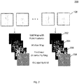
- Fig. 2 shows an illustration 200 of generating radar detection data and radar maps according to various embodiments.
- the ego-location compensated radar sensor data 108 may be processed to obtain grid maps with point features 202, motion maps 204, positional uncertainty maps 206, and occupancy maps 208 (in other words: occupancy grids).
- respective maps or grids may be determined for each time step, so that a plurality of maps and grids are determined.
- Radar points can be assigned to grid cells according to their spatial positions to obtain the grid maps with point features 202 (for example RCS, range rate, absolute position, relative position to cell center etc.). This may be done outside the network in an offline manner.
- the scope and resolution of the grid may be predefined.
- the grid may have a width W and a height H, so that the grid has W x H grid cells.
- every grid cell may include a fixed (predefined or pre-determined) number of points. If there are less points in a cell than the fixed number, upsampling is used, otherwise downsampling is used. Every point is represented by some features e.g. RCS, range rate, absolute position, relative position to cell center etc. Therefore, the input data from points may be represented by a tensor of dimension HxWxNxF, where N is the number of points in each cell and F is the number of point features.
- Motion maps may be represented by a tensor of dimension HxWxC M , wherein C M represents the numbers of feature channels in the motion map.
- Motion maps may spread the point information of a Doppler speed measurement to into space where convolutional layers (for example of neural networks) are able to encode strong semantic features.
- Motion maps may represent the cumulative probability of existence of radar point detections in the next frame (in other words: at the next time step).
- the radial ego-motion (or ego-location) compensated component of the object speed may be calculated. Therefore, for each radar point detection, the radial covered distance may be computed.
- the uncertainty of the translative covered distance may be drawn as a line. Additionally, a Gaussian uncertainty along this line may be drawn in radial direction. The length of this line may be set to a given value and symmetric to the center of the original point position.
- the update of each gridcell may be done in a cumulative manner.
- An example of a motion map design will be provided below with reference to
- Uncertainty maps may be represented by a tensor of dimension HxWxC U , wherein C U represents the numbers of feature channels in the uncertainty map. Uncertainty maps may represent the positional uncertainty in the current frame (in other words: at the current time step). Using an inverse sensor model, similar to the creation of occupancy gridmaps, this uncertainty may be computed depending on the azimuth, distance and sensor properties, for example look type and range/angle measurement uncertainties. The positional uncertainty may get lower the farther the grid cell is away from the determined measured position. The update of each gridcell may be done in a cumulative manner.
- Occupancy maps may be represented by a tensor of dimension HxWxC O , wherein C O represents the numbers of feature channels in the occupancy map.
- Occupancy maps may apply time fusion in order to create a map of only static object contours. Moving objects may rarely be visible in this kind of maps.
- the uncertainty map of each frame is ego-location compensated to a given time. Then, this maps are fused in a Bayes scheme.
- Each grid cell may represent their probability of object existence. The more radar point detections contribute to a cell, the higher the probability of existence will be.
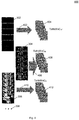
- Fig. 3 shows an illustration 300 of a stacking process according to various embodiments. Radar points from single time step are often not stable, and meaningful information may be inferred only by considering multiple frames. According to various embodiments, multiple frames may be stacked together to encode temporal information. In the stacking process, ego-motion may be considered to compensate the moving of ego-vehicle (in other words: of the vehicle on which the radar sensor is provided). As such, all the points from stationary objects may always be at the same grid position within multiple frames.
- Grid maps with point features 202 of various time steps may be stacked to obtain a stacked grid map with point features 302 (which may be represented by a tensor of dimensions TxHxWxNxF, wherein T may denote the number of time steps that are stacked).
- Motion maps 204 of various time steps may be stacked to obtain a stacked motion map 304 (which may be represented by a tensor of dimensions TxHxWxC M ).
- Positional uncertainty maps 206 of various time steps may be stacked to obtain a stacked positional uncertainty map 306 (which may be represented by a tensor of dimensions TxHxWxC U ).
- Occupancy grids 208 of various time steps may be stacked to obtain a stacked occupancy grid (which may be represented by a tensor of dimensions TxHxWxC O ). Like indicated by points 308 further maps of various time steps may be stacked. The stacked maps and grids may be provided as input to a (neural) network for further processing.
- the neural network for object detection may take the input of 3D tensor (HxWxC) where C is the number of feature channels. It will be understood that commonly used neural networks may be used.
- a feature encoding layer is provided to convert the inputs (one 5D tensor and three 4-D tensor) into a unified 3D tensor.
- the feature encoding layer may extract features from points and maps, may squeeze the dimension of points (e.g. by max pooling) and may then concatenate all of them to get a unified 4D tensor (of dimensions TxHxWxF', wherein F' is the sum of the fourth dimension of the representations to be concatenated).
- Fig. 4 shows an illustration 400 of feature encoding according to various embodiments.
- the stacked grid map with point features 302 may be processed by time-distributed convolutions402, to obtain a point representation 404 (for example a 4D-tensor, for example of dimensions TxHxWxC NF , wherein C NF is a dimension that results from squeezing the dimension NxF of point features).
- the stacked motion map 304 may be processed by time-distributed convolutions 406 to obtain a motion map representation 408 (for example a 4D-tensor, for example of dimensions TxHxWxC M ).
- the stacked positional uncertainty map 306 may be processed by time-distributed convolutions 410 to obtain a positional uncertainty map representation 412 (for example a 4D-tensor, for example of dimensions TxHxWxC U ). Further stacked maps may be processed accordingly (for example by time-distributed CNNs) to get further map representations (for example 4D-tensors).
- a positional uncertainty map representation 412 for example a 4D-tensor, for example of dimensions TxHxWxC U .
- Further stacked maps may be processed accordingly (for example by time-distributed CNNs) to get further map representations (for example 4D-tensors).
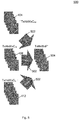
- Fig. 5 shows an illustration 500 of concatenating representations according to various embodiments.
- the point representation 404, the motion map representation 408, and the positional uncertainty map representation 412 may be concatenated, like illustrated by arrows 502, to obtain concatenated data 504. It will be understood that concatenation is possible since the point representation 404, the motion map representation 408, and the positional uncertainty map representation 412 have dimensions which are at least partially identical (for example, the first dimension (corresponding to the number of time steps, for example 5), the second dimension (corresponding to the height of the grid, for example 160), and the third dimension (corresponding to the width of the grid, for example 160) are identical for the point representation 404, the motion map representation 408, and the positional uncertainty map representation 412.
- the first dimension of the concatenated data 504 may be identical to the first dimension of the point representation 404, and identical to the first dimension of the motion map representation 408, and identical to the first dimension of the positional uncertainty map representation 412.
- the second dimension of the concatenated data 504 may be identical to the second dimension of the point representation 404, and identical to the second dimension of the motion map representation 408, and identical to the second dimension of the positional uncertainty map representation 412.
- the third dimension of the concatenated data 504 may be identical to the third dimension of the point representation 404, and identical to the third dimension of the motion map representation 408, and identical to the third dimension of the positional uncertainty map representation 412.
- the fourth dimension of the concatenated data 504 (for example 128 as illustrated in Fig.
- the fourth dimension of the point representation 404 may be identical to the sum of the fourth dimension of the point representation 404 (for example 64 as illustrated in Fig. 5 ), the fourth dimension of the motion map representation 408 (for example 32 as illustrated in Fig. 5 ), and the fourth dimension of the positional uncertainty map representation 412 (for example 32 as illustrated in Fig. 5 ).
- a time fusion layer may be provided to squeeze the time dimension.
- 3D conv or a recurrent network for example LSTM
- the output of this layer may be HxWxF" (with an integer number F"), which may be directly used by an object detection network.
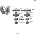
- Fig. 6 shows an illustration 600 of time squeezing according to various embodiments.
- the concatenated data may be provided using time-distributed convolutions (for example using 3D-conv or LSTM) 602, to obtain a pyramid with levels of data of reduced size and upsampled size.
- a first level 604 (for example of dimension T 1 xH 1 xW 1 xC 1 , which may be identical to TxHxWxF') may be processed, for example using convolutions and/ or max pooling to obtain a second level 606 of reduced size (for example T 2 xH 2 xW 2 xC 2 ).
- Level 614 may be obtained based on upsampling level 612 and based on level 608, for example by squeezing the time dimension. Data of level 614 may have dimensions H 3 xW 3 xC 3 , i.e. compared to the dimension of level 608, the time dimension T may be squeezed.
- Level 616 may have dimensions H 2 xW 2 xC 2 , i.e. compared to the dimension of level 606, the time dimension T may be squeezed.
- Data of level 618 may have dimensions H 1 xW 1 xC 1 , i.e. compared to the dimension of level 604, the time dimension T may be squeezed. Any of the levels 616, 618, or the further levels may be obtained based on a lower level that has been obtained based on upsampling and time squeezing (for example a level illustrated in Fig.
- a level that was obtained by downsampling for example a level illustrated in Fig. 6 left from the respective level
- levels 604, 606, 608, 610 may be processed to squeeze time dimension T, to obtain levels 618, 616, 614, 612, respectively.
- Various methods may be used for squeezing the time dimension, for example taking one of the subtensors for a fixed time value (in other words: taking one of the T maps), averaging over all time values (in other words: averaging over all maps along T dimension), taking a maximal or minimal value of all subtensors (in other words: maps) along T dimension, add-up values of all subtensors (in other words: maps) along T dimension, or any other method for removing or reducing the time dimension.
- the output of level 618 may be used for object detection.
- Fig. 7 shows an illustration 700 of object detection according to various embodiments.
- the output of level 618 may be used for object detection 702, for example using an anchor-based object detection network, for example using Retinanet (or a similar network) on each pyramid level feature map, or any other object detection method.
- object detection 702 for example using an anchor-based object detection network, for example using Retinanet (or a similar network) on each pyramid level feature map, or any other object detection method.
- Fig. 8 shows an illustration 800 of a motion map design for instantaneous probability calculation in a next frame (in other words: at a next (in other words: subsequent) time step) according to various embodiments.
- a vehicle 802 with a radar sensor 802, a radar point detection 804, a radial velocity 806, a distance 808 covered in the next frame, and a positional uncertainty 810 in the next frame are illustrated.
- Fig. 9 shows a flow diagram 900 illustrating a computer implemented method for object detection according to various embodiments.
- a grid may be determined.
- the grid may include a plurality of grid cells.
- a plurality of respective radar detection data for each grid cell may be determined for a plurality of time steps.
- Each radar detection data may indicate a plurality of radar properties.
- a respective radar map indicating a pre-determined radar map property in each grid cell may be determined for each time step.
- the respective radar detection data of the plurality of grid cells for the plurality of time steps may be converted to a point representation of pre-determined first dimensions.
- the radar maps for the plurality of time steps may be converted to a map representation of pre-determined second dimensions.
- the pre-determined first dimensions and the pre-determined second dimensions may be at least partially identical.
- the point representation and the map representation may be concatenated to obtain concatenated data.
- out object detection may be carried based on the concatenated data.
- the computer implemented method may further comprise receiving radar sensor data for each time step from a radar sensor provided on a vehicle; and preprocessing the radar sensor data to remove an effect of a change in location of the vehicle.
- the radar detection data and the radar maps may be determined based on the preprocessed radar sensor data.
- the radar sensor data may be preprocessed to remove the effect of the change in location of the vehicle based on the radar sensor data of the present time step and radar sensor data of a pre-determined number of previous time steps preceding the present time step.
- the respective radar map may comprise a motion map indicating a probability of existence of a radar point detection at a next time step.
- the respective radar map may comprise a positional uncertainty map indicating a positional uncertainty at the respective time step.
- the respective radar map may comprise an occupancy map indicating static object contours.
- converting the respective radar detection data of the plurality of grid cells for the plurality of time steps to the point representation of pre-determined first dimensions may include reducing a dimension of points in each cell.
- reducing the dimension of points may include max pooling.
- the grid may comprise a pre-determined height and a pre-determined width.
- the point representation may comprise a four-dimensional point tensor. A first dimension of the point tensor may correspond to the number of the plurality of time steps, a second dimension of the point tensor may correspond to the height of the grid, and a third dimension of the point tensor may correspond to the width of the grid.
- the map representation may comprise a four-dimensional map tensor. A first dimension of the map tensor may correspond to the number of the plurality of time steps, a second dimension of the map tensor may correspond to the height of the grid, and a third dimension of the map tensor may correspond to the width of the grid.
- the concatenated data may comprise a four-dimensional concatenated tensor.
- a first dimension of the concatenated tensor may correspond to the number of the plurality of time steps
- a second dimension of the concatenated tensor may correspond to the height of the grid
- a third dimension of the concatenated tensor may correspond to the width of the grid
- a fourth dimension of the concatenated tensor may correspond to the sum of a fourth dimension of the point tensor and a fourth dimension of the map tensor.
- the computer implemented method may further comprise: reducing the dimension of the concatenated data to get time fused data.
- the time fused data may comprise a three-dimensional time fused tensor.
- a first dimension of the time fused tensor may correspond to the height of the grid
- a second dimension of the time fused tensor may correspond to the width of the grid
- a third dimension of the time fused tensor may correspond to the sum of a fourth dimension of the point tensor and a fourth dimension of the map tensor.
- Object detection may be carried out based on the time fused data.
- reducing the dimension of the concatenated data may comprise using a 3D convolution. According to various embodiments, reducing the dimension of the concatenated data may comprise using a recurrent network.
- steps 902, 904, 906, 908, 910, 912, 914 and the further steps described above may be performed by computer hardware components.
- object detection based on radar point cloud and temporal fusion may be provided.
Landscapes
- Engineering & Computer Science (AREA)
- Remote Sensing (AREA)
- Radar, Positioning & Navigation (AREA)
- Physics & Mathematics (AREA)
- General Physics & Mathematics (AREA)
- Computer Networks & Wireless Communication (AREA)
- Electromagnetism (AREA)
- Theoretical Computer Science (AREA)
- Artificial Intelligence (AREA)
- Evolutionary Computation (AREA)
- Biophysics (AREA)
- Data Mining & Analysis (AREA)
- Computing Systems (AREA)
- General Engineering & Computer Science (AREA)
- General Health & Medical Sciences (AREA)
- Mathematical Physics (AREA)
- Software Systems (AREA)
- Molecular Biology (AREA)
- Computational Linguistics (AREA)
- Biomedical Technology (AREA)
- Life Sciences & Earth Sciences (AREA)
- Health & Medical Sciences (AREA)
- Radar Systems Or Details Thereof (AREA)
- Traffic Control Systems (AREA)
Abstract
Description
- The present disclosure relates to methods and systems for object detection. Radar detection data and radar map data may be combined and reduced in dimension to provide efficient object detection.
- Radar is a commonly used sensor in automotive perception systems due to its low cost compared with LiDAR and high adaptability to environment changes (e.g. weather or lighting condition) compared with cameras.
- Radar data is usually given in the form of point clouds. Each point is characterized by some features, e.g. its RCS (Radar Cross-Section), range rate (Doppler velocity) and spatial location. In automotive perception systems, it may be desired to carry out object detection (for example predicting the location and/ or motion of objects and/ or carrying out semantic segmentation for determining a semantic label of every location).
- According to conventional methods, performance of predicting the location and/ or motion of objects may still be improved.
- Accordingly, there is a need to provide systems and methods for enhanced object detection.
- The present disclosure provides a computer implemented method, a computer system and a non-transitory computer readable medium according to the independent claims. Embodiments are given in the subclaims, the description and the drawings.
- In one aspect, the present disclosure is directed at a computer implemented method for object detection, the method comprising the following steps carried out by computer hardware components: determining a grid, the grid comprising a plurality of grid cells; determining, for a plurality of time steps, for each grid cell, a plurality of respective radar detection data, each radar detection data indicating a plurality of radar properties; determining, for each time step, a respective radar map indicating a pre-determined radar map property in each grid cell; converting the respective radar detection data of the plurality of grid cells for the plurality of time steps to a point representation of pre-determined first dimensions; converting the radar maps for the plurality of time steps to a map representation of pre-determined second dimensions, wherein the pre-determined first dimensions and the pre-determined second dimensions are at least partially identical; concatenating the point representation and the map representation to obtain concatenated data; and carrying out object detection based on the concatenated data.
- In other words, radar detection data (which may also be referred to as point-cloud data) and map data may be brought into respective representations which are of dimensions which are suitable for concatenating the representations. For example, the representations may be tensors, which have dimensions that match in all but one dimension. Concatenating these tensors may then lead to a tensor in which only the dimension, in which the tensors do not match, is changed (for example to the sum of the respective dimension of the tensors), while the dimensions in which the tensors match remains unchanged.
- It has been found that combining (for example concatenating) radar detection data and map data into combined (for example concatenated) data may improve detection results when using the combined data as input data to a neural network.
- According to another aspect, the computer implemented method may further comprise: receiving radar sensor data for each time step from a radar sensor provided on a vehicle; and preprocessing the radar sensor data to remove an effect of a change in location of the vehicle. The radar detection data and the radar maps may be determined based on the preprocessed radar sensor data.
- The vehicle may be moving, i.e. the vehicle may change its location (for example change its position and/ or its orientation). Removing the effect of the change in location of the vehicle (for example removing the effect of the change in position and orientation of the vehicle between two or more time steps) may provide that the radar sensor data is always given in the same global coordinate system. Removing the effect of the change in location of the vehicle may also be referred to as ego-location compensation.
- According to another aspect, for each present time step, the radar sensor data may be preprocessed to remove the effect of the change in location of the vehicle based on the radar sensor data of the present time step and radar sensor data of a pre-determined number of previous time steps preceding the present time step.
- Taking into account the radar sensor data of the present time step and a pre-determined number of previous time steps preceding the present time step when removing the effect of the change in location of the vehicle may provide a sliding window of constant (time) length, and may provide that all radar detection data and radar maps (that are converted into point representation and map representations and are then concatenated) are provided in the same coordinate system.
- According to another aspect, for each time step, the respective radar map may comprise a motion map indicating a probability of existence of a radar point detection at a next time step. According to another aspect, for each time step, the respective radar map may comprise a positional uncertainty map indicating a positional uncertainty at the respective time step. According to another aspect, for each time step, the respective radar map may comprise an occupancy map indicating static object contours.
- It will be understood that more than one kind of radar map may be provided, for example two of the motion map, positional uncertainty map, and occupancy map, or all three kinds of radar maps (motion maps, positional uncertainty maps, and occupancy maps). It will also be understood that in such a case, the steps of determining, for each time step, the respective radar map indicating the pre-determined radar map property (in other words: the property indicated by the radar map) in each grid cell may be provided for each kind of map, and the step of converting the radar map for the plurality of time steps to a map representation may be provided for each kind of map. The dimensions of the various map representations may at least partially be identical to the dimensions of the point representation. It will further be understood that the step of concatenating may include concatenating the points and the various kinds of maps.
- According to another aspect, converting the respective radar detection data of the plurality of grid cells for the plurality of time steps to the point representation of pre-determined first dimensions may comprise reducing a dimension of points in each cell. Reducing the dimension of points in each cell may be also be referred to as squeezing. According to another aspect, reducing the dimension of points may comprise max pooling.
- According to another aspect, the grid may comprise a pre-determined height and a pre-determined width; the point representation may comprise a four-dimensional tensor (which may be referred to as point tensor or as tensor of the point representation), wherein a first dimension of the point tensor corresponds to the number of the plurality of time steps, a second dimension of the point tensor corresponds to the height of the grid, and a third dimension of the point tensor corresponds to the width of the grid; and the map representation may comprise a four-dimensional tensor (which may be referred to as map tensor or as tensor of the map representation), wherein a first dimension of the map tensor corresponds to the number of the plurality of time steps, a second dimension of the map tensor corresponds to the height of the grid, and a third dimension of the map tensor corresponds to the width of the grid.
- It has been found that with these dimensions of the tensors, an efficient concatenation of the point representation and the map representation may be carried out.
- According to another aspect, the concatenated data may comprise a four-dimensional tensor (which may be referred to as concatenated tensor or as tensor of the concatenated data), wherein a first dimension of the concatenated tensor corresponds to the number of the plurality of time steps, a second dimension of the concatenated tensor corresponds to the height of the grid, a third dimension of the concatenated tensor corresponds to the width of the grid, and a fourth dimension of the concatenated tensor corresponds to the sum of a fourth dimension of the point tensor and a fourth dimension of the map tensor.
- The concatenated data may be represented by a tensor which in all but one dimension matches the dimensions of the tensor of the point representation and the tensor of the map representation, and the remaining dimension may be the sum of the dimensions of the tensors of the point representation and the map representation. With such concatenated data, the point representation and the map representation may be provided in a unified set of data, which may increase the content of information, and may thus provide useful input for object detection.
- According to another aspect, the computer implemented method may further comprise: reducing the dimension of the concatenated data to get time fused data, wherein the time fused data comprises a three-dimensional tensor (which may be referred to as time fused tensor or as tensor of the time fused data), wherein a first dimension of the time fused tensor corresponds to the height of the grid, a second dimension of the time fused tensor corresponds to the width of the grid, and a third dimension of the time fused tensor corresponds to the sum of a fourth dimension of the point tensor and a fourth dimension of the map tensor; wherein object detection is carried out based on the time fused data.
- The time fused data may be represented by a tensor of a dimension which is one lower than the dimension of the tensor of the concatenated data. For example, the first dimension (for example corresponding to the time steps) may be removed (in other words: fused), for example the concatenated data may be represented by a four-dimensional tensor, and the time fused data may be represented by a three-dimensional tensor.
- According to another aspect, reducing the dimension of the concatenated data may comprise using a 3D convolution. According to another aspect, reducing the dimension of the concatenated data may comprise using a recurrent network.
- It has been found that 3D conv (3D convolution) or a recurrent network (for example LSTM) provide an efficient way of reducing the dimension of the concatenated data.
- In another aspect, the present disclosure is directed at a computer system, said computer system comprising a plurality of computer hardware components configured to carry out several or all steps of the computer implemented method described herein.
- The computer system may comprise a plurality of computer hardware components (for example a processing unit (in other words: processor), at least one memory unit (which may also be referred to as memory) and at least one non-transitory data storage, for example hard disk drive or solid-state drive). It will be understood that further computer hardware components may be provided and used for carrying out steps of the computer implemented method in the computer system. The non-transitory data storage and/or the memory unit may comprise a computer program for instructing the computer to perform several or all steps or aspects of the computer implemented method described herein, for example using the processing unit and the at least one memory unit.
- In another aspect, the present disclosure is directed at a non-transitory computer readable medium comprising instructions for carrying out several or all steps or aspects of the computer implemented method described herein. The computer readable medium may be configured as: an optical medium, such as a compact disc (CD) or a digital versatile disk (DVD); a magnetic medium, such as a hard disk drive (HDD); a solid state drive (SSD); a read only memory (ROM), such as a flash memory; or the like. Furthermore, the computer readable medium may be configured as a data storage that is accessible via a data connection, such as an internet connection. The computer readable medium may, for example, be an online data repository or a cloud storage.
- The present disclosure is also directed at a computer program for instructing a computer to perform several or all steps or aspects of the computer implemented method described herein.
- Exemplary embodiments and functions of the present disclosure are described herein in conjunction with the following drawings, showing schematically:
- Fig. 1
- an illustration of generating ego-location compensated radar sensor data for further processing according to various embodiments;
- Fig. 2
- an illustration of generating radar detection data and radar maps according to various embodiments;
- Fig. 3
- an illustration of a stacking process according to various embodiments;
- Fig. 4
- an illustration of feature encoding according to various embodiments;
- Fig. 5
- an illustration of concatenating representations according to various embodiments;
- Fig. 6
- an illustration of time squeezing according to various embodiments;
- Fig. 7
- an illustration of object detection according to various embodiments;
- Fig. 8
- shows an illustration of a motion map design for instantaneous probability calculation in a next frame according to various embodiments; and
- Fig. 9
- a flow diagram illustrating a computer implemented method for object detection according to various embodiments.
-
Fig. 1 to Fig. 7 show portions of a (neural) network structure according to various embodiments to process points, grid maps as well as time fusion. Processing shown inFig. 1 ,Fig. 2 , andFig. 3 may provide the inputs, processing shown inFig. 4 andFig. 5 may provide a feature encoding layer, processing shown inFig. 6 may provide a time fusion layer, and processing shown inFig. 7 may provide object detection. - Deep convolutional neural networks (CNN) may be used for various perception tasks, e.g. object detection and/ or semantic segmentation. The input to a neural network may be a multiple dimensional tensor, e.g. a 2-D tensor or a 3-D tensor, which may be defined in certain spatial coordinate system. Every grid cell may include either points or some pre-calculated features.
-
Fig. 1 shows anillustration 100 of generating ego-location compensated radar sensor data for further processing according to various embodiments. A plurality ofradar sensor data 102 at a plurality of time steps T0, T1, ..., T8, T9, T10, ..., TN are illustrated. A slidingwindow 104 may be provided to use radar sensor data from a present time step (for example T9 as illustrated inFig. 1 ) and radar sensor data from a pre-determined number of preceding time steps (for example from 9 preceding time steps T0, T1, ..., T8 as illustrated inFig. 1 ), and may carry out ego-location compensation 106 based on the radar sensor data in the slidingwindow 104. - The ego-location compensated
radar sensor data 108 may be used for further processing. According to various embodiments, points (in other words: point features or point properties) and one or more kinds of (precalculated) maps (for example motion maps, uncertainty maps and/ or occupancy maps) may be determined based on the ego-location compensatedradar sensor data 108, and may be provided to the network according to various embodiments as inputs sources. -
Fig. 2 shows anillustration 200 of generating radar detection data and radar maps according to various embodiments. The ego-location compensatedradar sensor data 108 may be processed to obtain grid maps with point features 202, motion maps 204, positional uncertainty maps 206, and occupancy maps 208 (in other words: occupancy grids). Like illustrated inFig. 2 , respective maps or grids may be determined for each time step, so that a plurality of maps and grids are determined. - Radar points can be assigned to grid cells according to their spatial positions to obtain the grid maps with point features 202 (for example RCS, range rate, absolute position, relative position to cell center etc.). This may be done outside the network in an offline manner. The scope and resolution of the grid may be predefined. For example, the grid may have a width W and a height H, so that the grid has W x H grid cells. After assignment, every grid cell may include a fixed (predefined or pre-determined) number of points. If there are less points in a cell than the fixed number, upsampling is used, otherwise downsampling is used. Every point is represented by some features e.g. RCS, range rate, absolute position, relative position to cell center etc. Therefore, the input data from points may be represented by a tensor of dimension HxWxNxF, where N is the number of points in each cell and F is the number of point features.
- Motion maps may be represented by a tensor of dimension HxWxCM, wherein CM represents the numbers of feature channels in the motion map. Motion maps may spread the point information of a Doppler speed measurement to into space where convolutional layers (for example of neural networks) are able to encode strong semantic features. Motion maps may represent the cumulative probability of existence of radar point detections in the next frame (in other words: at the next time step). For example, the radial ego-motion (or ego-location) compensated component of the object speed may be calculated. Therefore, for each radar point detection, the radial covered distance may be computed. The uncertainty of the translative covered distance may be drawn as a line. Additionally, a Gaussian uncertainty along this line may be drawn in radial direction. The length of this line may be set to a given value and symmetric to the center of the original point position. The update of each gridcell may be done in a cumulative manner. An example of a motion map design will be provided below with reference to
Fig. 8 . - Uncertainty maps may be represented by a tensor of dimension HxWxCU, wherein CU represents the numbers of feature channels in the uncertainty map. Uncertainty maps may represent the positional uncertainty in the current frame (in other words: at the current time step). Using an inverse sensor model, similar to the creation of occupancy gridmaps, this uncertainty may be computed depending on the azimuth, distance and sensor properties, for example look type and range/angle measurement uncertainties. The positional uncertainty may get lower the farther the grid cell is away from the determined measured position. The update of each gridcell may be done in a cumulative manner.
- Occupancy maps may be represented by a tensor of dimension HxWxCO, wherein CO represents the numbers of feature channels in the occupancy map. Occupancy maps may apply time fusion in order to create a map of only static object contours. Moving objects may rarely be visible in this kind of maps. First, the uncertainty map of each frame is ego-location compensated to a given time. Then, this maps are fused in a Bayes scheme. Each grid cell may represent their probability of object existence. The more radar point detections contribute to a cell, the higher the probability of existence will be.
-
Fig. 3 shows anillustration 300 of a stacking process according to various embodiments. Radar points from single time step are often not stable, and meaningful information may be inferred only by considering multiple frames. According to various embodiments, multiple frames may be stacked together to encode temporal information. In the stacking process, ego-motion may be considered to compensate the moving of ego-vehicle (in other words: of the vehicle on which the radar sensor is provided). As such, all the points from stationary objects may always be at the same grid position within multiple frames. - Grid maps with point features 202 of various time steps may be stacked to obtain a stacked grid map with point features 302 (which may be represented by a tensor of dimensions TxHxWxNxF, wherein T may denote the number of time steps that are stacked). Motion maps 204 of various time steps may be stacked to obtain a stacked motion map 304 (which may be represented by a tensor of dimensions TxHxWxCM). Positional uncertainty maps 206 of various time steps may be stacked to obtain a stacked positional uncertainty map 306 (which may be represented by a tensor of dimensions TxHxWxCU).
Occupancy grids 208 of various time steps may be stacked to obtain a stacked occupancy grid (which may be represented by a tensor of dimensions TxHxWxCO). Like indicated bypoints 308 further maps of various time steps may be stacked. The stacked maps and grids may be provided as input to a (neural) network for further processing. - The neural network for object detection according to various embodiments may take the input of 3D tensor (HxWxC) where C is the number of feature channels. It will be understood that commonly used neural networks may be used. According to various embodiments, a feature encoding layer is provided to convert the inputs (one 5D tensor and three 4-D tensor) into a unified 3D tensor. According to various embodiments, the feature encoding layer may extract features from points and maps, may squeeze the dimension of points (e.g. by max pooling) and may then concatenate all of them to get a unified 4D tensor (of dimensions TxHxWxF', wherein F' is the sum of the fourth dimension of the representations to be concatenated).
-
Fig. 4 shows anillustration 400 of feature encoding according to various embodiments. The stacked grid map with point features 302 may be processed by time-distributed convolutions402, to obtain a point representation 404 (for example a 4D-tensor, for example of dimensions TxHxWxCNF, wherein CNF is a dimension that results from squeezing the dimension NxF of point features). The stackedmotion map 304 may be processed by time-distributedconvolutions 406 to obtain a motion map representation 408 (for example a 4D-tensor, for example of dimensions TxHxWxCM). The stackedpositional uncertainty map 306 may be processed by time-distributedconvolutions 410 to obtain a positional uncertainty map representation 412 (for example a 4D-tensor, for example of dimensions TxHxWxCU). Further stacked maps may be processed accordingly (for example by time-distributed CNNs) to get further map representations (for example 4D-tensors). -
Fig. 5 shows anillustration 500 of concatenating representations according to various embodiments. Thepoint representation 404, themotion map representation 408, and the positionaluncertainty map representation 412 may be concatenated, like illustrated byarrows 502, to obtain concatenateddata 504. It will be understood that concatenation is possible since thepoint representation 404, themotion map representation 408, and the positionaluncertainty map representation 412 have dimensions which are at least partially identical (for example, the first dimension (corresponding to the number of time steps, for example 5), the second dimension (corresponding to the height of the grid, for example 160), and the third dimension (corresponding to the width of the grid, for example 160) are identical for thepoint representation 404, themotion map representation 408, and the positionaluncertainty map representation 412. The concatenateddata 504 may be a tensor of dimensions TxHxWxF' (wherein F' may be the sum of the channel dimensions of the data to be concatenated; in the example ofFig. 5 , it may hold that F'=CNF+CM+CU). - The first dimension of the concatenated
data 504 may be identical to the first dimension of thepoint representation 404, and identical to the first dimension of themotion map representation 408, and identical to the first dimension of the positionaluncertainty map representation 412. The second dimension of the concatenateddata 504 may be identical to the second dimension of thepoint representation 404, and identical to the second dimension of themotion map representation 408, and identical to the second dimension of the positionaluncertainty map representation 412. The third dimension of the concatenateddata 504 may be identical to the third dimension of thepoint representation 404, and identical to the third dimension of themotion map representation 408, and identical to the third dimension of the positionaluncertainty map representation 412. The fourth dimension of the concatenated data 504 (for example 128 as illustrated inFig. 5 ) may be identical to the sum of the fourth dimension of the point representation 404 (for example 64 as illustrated inFig. 5 ), the fourth dimension of the motion map representation 408 (for example 32 as illustrated inFig. 5 ), and the fourth dimension of the positional uncertainty map representation 412 (for example 32 as illustrated inFig. 5 ). - A time fusion layer may be provided to squeeze the time dimension. For example, 3D conv or a recurrent network (for example LSTM) may be used on the time dimension. The output of this layer may be HxWxF" (with an integer number F"), which may be directly used by an object detection network.
-
Fig. 6 shows anillustration 600 of time squeezing according to various embodiments. The concatenated data may be provided using time-distributed convolutions (for example using 3D-conv or LSTM) 602, to obtain a pyramid with levels of data of reduced size and upsampled size. A first level 604 (for example of dimension T1xH1xW1xC1, which may be identical to TxHxWxF') may be processed, for example using convolutions and/ or max pooling to obtain a second level 606 of reduced size (for example T2xH2xW2xC2). Further size reduction may be applied, to obtain further levels (of which levels 608 (for example with dimensions T3xH3xW3xC3 and 610 are illustrated; it will however be understood that further levels may be present). It will be understood thatlevel 610 may be a scalar, so thatlevel 612 is identical tolevel 610.Level 614 may be obtained based onupsampling level 612 and based onlevel 608, for example by squeezing the time dimension. Data oflevel 614 may have dimensions H3xW3xC3, i.e. compared to the dimension oflevel 608, the time dimension T may be squeezed. Further upsampled levels may be provided, of whichlevels level 616 may have dimensions H2xW2xC2, i.e. compared to the dimension of level 606, the time dimension T may be squeezed. Data oflevel 618 may have dimensions H1xW1xC1, i.e. compared to the dimension oflevel 604, the time dimension T may be squeezed. Any of thelevels Fig. 6 below the respective level), and a level that was obtained by downsampling (for example a level illustrated inFig. 6 left from the respective level). In the levels that were obtained by downsampling, forexample levels levels level 618 may be used for object detection. -
Fig. 7 shows anillustration 700 of object detection according to various embodiments. The output oflevel 618 may be used forobject detection 702, for example using an anchor-based object detection network, for example using Retinanet (or a similar network) on each pyramid level feature map, or any other object detection method. -
Fig. 8 shows anillustration 800 of a motion map design for instantaneous probability calculation in a next frame (in other words: at a next (in other words: subsequent) time step) according to various embodiments. Avehicle 802 with aradar sensor 802, aradar point detection 804, aradial velocity 806, adistance 808 covered in the next frame, and apositional uncertainty 810 in the next frame are illustrated. -
Fig. 9 shows a flow diagram 900 illustrating a computer implemented method for object detection according to various embodiments. At 902, a grid may be determined. The grid may include a plurality of grid cells. At 904, a plurality of respective radar detection data for each grid cell may be determined for a plurality of time steps. Each radar detection data may indicate a plurality of radar properties. At 906, a respective radar map indicating a pre-determined radar map property in each grid cell may be determined for each time step. At 908, the respective radar detection data of the plurality of grid cells for the plurality of time steps may be converted to a point representation of pre-determined first dimensions. At 910, the radar maps for the plurality of time steps may be converted to a map representation of pre-determined second dimensions. The pre-determined first dimensions and the pre-determined second dimensions may be at least partially identical. At 912, the point representation and the map representation may be concatenated to obtain concatenated data. At 914, out object detection may be carried based on the concatenated data. - According to various embodiments, the computer implemented method may further comprise receiving radar sensor data for each time step from a radar sensor provided on a vehicle; and preprocessing the radar sensor data to remove an effect of a change in location of the vehicle. The radar detection data and the radar maps may be determined based on the preprocessed radar sensor data.
- According to various embodiments, for each present time step, the radar sensor data may be preprocessed to remove the effect of the change in location of the vehicle based on the radar sensor data of the present time step and radar sensor data of a pre-determined number of previous time steps preceding the present time step.
- According to various embodiments, for each time step, the respective radar map may comprise a motion map indicating a probability of existence of a radar point detection at a next time step.
- According to various embodiments, for each time step, the respective radar map may comprise a positional uncertainty map indicating a positional uncertainty at the respective time step.
- According to various embodiments, for each time step, the respective radar map may comprise an occupancy map indicating static object contours.
- According to various embodiments, converting the respective radar detection data of the plurality of grid cells for the plurality of time steps to the point representation of pre-determined first dimensions may include reducing a dimension of points in each cell.
- According to various embodiments, reducing the dimension of points may include max pooling.
- According to various embodiments, the grid may comprise a pre-determined height and a pre-determined width. The point representation may comprise a four-dimensional point tensor. A first dimension of the point tensor may correspond to the number of the plurality of time steps, a second dimension of the point tensor may correspond to the height of the grid, and a third dimension of the point tensor may correspond to the width of the grid. The map representation may comprise a four-dimensional map tensor. A first dimension of the map tensor may correspond to the number of the plurality of time steps, a second dimension of the map tensor may correspond to the height of the grid, and a third dimension of the map tensor may correspond to the width of the grid.
- According to various embodiments, the concatenated data may comprise a four-dimensional concatenated tensor. A first dimension of the concatenated tensor may correspond to the number of the plurality of time steps, a second dimension of the concatenated tensor may correspond to the height of the grid, a third dimension of the concatenated tensor may correspond to the width of the grid, and a fourth dimension of the concatenated tensor may correspond to the sum of a fourth dimension of the point tensor and a fourth dimension of the map tensor.
- According to various embodiments, the computer implemented method may further comprise: reducing the dimension of the concatenated data to get time fused data. The time fused data may comprise a three-dimensional time fused tensor. A first dimension of the time fused tensor may correspond to the height of the grid, a second dimension of the time fused tensor may correspond to the width of the grid, and a third dimension of the time fused tensor may correspond to the sum of a fourth dimension of the point tensor and a fourth dimension of the map tensor. Object detection may be carried out based on the time fused data.
- According to various embodiments, reducing the dimension of the concatenated data may comprise using a 3D convolution. According to various embodiments, reducing the dimension of the concatenated data may comprise using a recurrent network.
- Each of the
steps - As described above, according to various embodiments, object detection based on radar point cloud and temporal fusion may be provided.
-
- 100
- illustration of generating ego-location compensated radar sensor data for further processing according to various embodiments
- 102
- radar sensor data
- 104
- sliding window
- 106
- ego-location compensation
- 108
- ego-location compensated radar sensor data
- 200
- illustration of generating radar detection data and radar maps according to various embodiments
- 202
- grid maps with point features
- 204
- motion maps
- 206
- positional uncertainty maps
- 208
- occupancy maps
- 300
- illustration of a stacking process according to various embodiments
- 302
- stacked grid map with point features
- 304
- stacked motion map
- 306
- stacked positional uncertainty map
- 308
- points indicating further stacked maps of various time steps
- 400
- illustration of feature encoding according to various embodiments
- 402
- time-distributed convolutions
- 404
- point representation
- 406
- time-distributed convolutions
- 408
- motion map representation
- 410
- time-distributed convolutions
- 412
- positional uncertainty map representation
- 500
- illustration of concatenating representations according to various embodiments
- 502
- arrow indicating concatenation
- 504
- concatenated data
- 600
- illustration of time squeezing according to various embodiments
- 602
- time-distributed convolutions
- 604
- first level
- 606
- second level
- 608
- further level
- 610
- further level
- 612
- further level
- 614
- further level
- 616
- further level
- 618
- further level
- 700
- illustration of object detection according to various embodiments
- 702
- object detection
- 800
- illustration of a motion map design for instantaneous probability calculation in a next frame according to various embodiments
- 802
- radar sensor
- 804
- radar point detection
- 806
- radial velocity
- 808
- distance
- 810
- positional uncertainty
- 900
- flow diagram illustrating a computer implemented method for object detection according to various embodiments
- 902
- method step
- 904
- method step
- 906
- method step
- 908
- method step
- 910
- method step
- 912
- method step
- 914
- method step
Claims (15)
- Computer implemented method for object detection,
the method comprising the following steps carried out by computer hardware components:- determining (902) a grid, the grid comprising a plurality of grid cells;- determining (904), for a plurality of time steps, for each grid cell, a plurality of respective radar detection data, each radar detection data indicating a plurality of radar properties;- determining (906), for each time step, a respective radar map indicating a pre-determined radar map property in each grid cell;- converting (908) the respective radar detection data of the plurality of grid cells for the plurality of time steps to a point representation of pre-determined first dimensions;- converting (910) the radar maps for the plurality of time steps to a map representation of pre-determined second dimensions, wherein the pre-determined first dimensions and the pre-determined second dimensions are at least partially identical;- concatenating (912) the point representation and the map representation to obtain concatenated data; and- carrying out object detection (914) based on the concatenated data. - The computer implemented method of claim 1, further comprising:receiving radar sensor data for each time step from a radar sensor provided on a vehicle; andpreprocessing the radar sensor data to remove an effect of a change in location of the vehicle;wherein the radar detection data and the radar maps are determined based on the preprocessed radar sensor data.
- The computer implemented method of claim 2,
wherein, for each present time step, the radar sensor data is preprocessed to remove the effect of the change in location of the vehicle based on the radar sensor data of the present time step and radar sensor data of a pre-determined number of previous time steps preceding the present time step. - The computer implemented method of at least one of claims 1 to 3,
wherein, for each time step, the respective radar map comprises a motion map indicating a probability of existence of a radar point detection at a next time step. - The computer implemented method of at least one of claims 1 to 4,
wherein, for each time step, the respective radar map comprises a positional uncertainty map indicating a positional uncertainty at the respective time step. - The computer implemented method of at least one of claims 1 to 5,
wherein, for each time step, the respective radar map comprises an occupancy map indicating static object contours. - The computer implemented method of at least one of claims 1 to 6,
wherein converting (908) the respective radar detection data of the plurality of grid cells for the plurality of time steps to the point representation of pre-determined first dimensions comprises reducing a dimension of points in each cell. - The computer implemented method of claim 7,
wherein reducing the dimension of points comprises max pooling. - The computer implemented method of at least one of claims 1 to 8,
wherein the grid comprises a pre-determined height and a pre-determined width;
wherein the point representation comprises a four-dimensional point tensor, wherein a first dimension of the point tensor corresponds to the number of the plurality of time steps, a second dimension of the point tensor corresponds to the height of the grid, and a third dimension of the point tensor corresponds to the width of the grid; and
wherein the map representation comprises a four-dimensional map tensor, wherein a first dimension of the map tensor corresponds to the number of the plurality of time steps, a second dimension of the map tensor corresponds to the height of the grid, and a third dimension of the map tensor corresponds to the width of the grid. - The computer implemented method of claim 9,
wherein the concatenated data comprises a four-dimensional concatenated tensor, wherein a first dimension of the concatenated tensor corresponds to the number of the plurality of time steps, a second dimension of the concatenated tensor corresponds to the height of the grid, a third dimension of the concatenated tensor corresponds to the width of the grid, and a fourth dimension of the concatenated tensor corresponds to the sum of a fourth dimension of the point tensor and a fourth dimension of the map tensor. - The computer implemented method of at least one of claims 9 to 10, further comprising:reducing the dimension of the concatenated data to get time fused data, wherein the time fused data comprises a three-dimensional time fused tensor, wherein a first dimension of the time fused tensor corresponds to the height of the grid, a second dimension of the time fused tensor corresponds to the width of the grid, and a third dimension of the time fused tensor corresponds to the sum of a fourth dimension of the point tensor and a fourth dimension of the map tensor;wherein object detection is carried out based on the time fused data.
- The computer implemented method of claim 11,
wherein reducing the dimension of the concatenated data comprises using a 3D convolution. - The computer implemented method of at least one of claims 11 to 12,
wherein reducing the dimension of the concatenated data comprises using a recurrent network. - Computer system, the computer system comprising a plurality of computer hardware components configured to carry out steps of the computer implemented method of at least one of claims 1 to 13.
- Non-transitory computer readable medium comprising instructions for carrying out the computer implemented method of at least one of claims 1 to 13.
Priority Applications (3)
| Application Number | Priority Date | Filing Date | Title |
|---|---|---|---|
| EP19187019.5A EP3767332B1 (en) | 2019-07-18 | 2019-07-18 | Methods and systems for radar object detection |
| US16/904,835 US11604272B2 (en) | 2019-07-18 | 2020-06-18 | Methods and systems for object detection |
| CN202010685414.8A CN112241008B (en) | 2019-07-18 | 2020-07-16 | Method and system for object detection |
Applications Claiming Priority (1)
| Application Number | Priority Date | Filing Date | Title |
|---|---|---|---|
| EP19187019.5A EP3767332B1 (en) | 2019-07-18 | 2019-07-18 | Methods and systems for radar object detection |
Publications (2)
| Publication Number | Publication Date |
|---|---|
| EP3767332A1 true EP3767332A1 (en) | 2021-01-20 |
| EP3767332B1 EP3767332B1 (en) | 2023-12-13 |
Family
ID=67438000
Family Applications (1)
| Application Number | Title | Priority Date | Filing Date |
|---|---|---|---|
| EP19187019.5A Active EP3767332B1 (en) | 2019-07-18 | 2019-07-18 | Methods and systems for radar object detection |
Country Status (3)
| Country | Link |
|---|---|
| US (1) | US11604272B2 (en) |
| EP (1) | EP3767332B1 (en) |
| CN (1) | CN112241008B (en) |
Cited By (2)
| Publication number | Priority date | Publication date | Assignee | Title |
|---|---|---|---|---|
| EP4075159A1 (en) * | 2021-04-14 | 2022-10-19 | Aptiv Technologies Limited | Radar system using a machine-learned model for stationary object detection |
| US12360240B2 (en) | 2022-10-07 | 2025-07-15 | Aptiv Technologies AG | Stationary object detection and classification based on low-level radar data |
Families Citing this family (13)
| Publication number | Priority date | Publication date | Assignee | Title |
|---|---|---|---|---|
| US12187323B2 (en) * | 2019-08-02 | 2025-01-07 | Hitachi Astemo, Ltd. | Aiming device, driving control system, and method for calculating correction amount of sensor data |
| CN116057411A (en) * | 2020-09-08 | 2023-05-02 | 西梅奥有限公司 | Measuring Vehicle Speed Using Multiple Vehicle Radars |
| DE102020216196A1 (en) * | 2020-12-17 | 2022-06-23 | Robert Bosch Gesellschaft mit beschränkter Haftung | Method for detecting at least one object in an environment using reflection signals from a radar sensor system |
| CN113267753B (en) * | 2021-05-13 | 2022-07-19 | 中国人民解放军军事科学院战争研究院 | Radar detection simulation method based on three-dimensional grid |
| KR20220160320A (en) * | 2021-05-27 | 2022-12-06 | 현대모비스 주식회사 | Apparatus amd method for monitoring surrounding environment of vehicle |
| CN113317791B (en) * | 2021-05-28 | 2023-03-14 | 温州康宁医院股份有限公司 | Method and device for determining severity of depression based on audio frequency of testee |
| CN113568068B (en) * | 2021-07-22 | 2022-03-29 | 河南大学 | Strong convection weather prediction method based on MPI parallel three-dimensional neural network |
| KR20230015658A (en) | 2021-07-23 | 2023-01-31 | 삼성전자주식회사 | Method for generating a grid map and apparatus thereof |
| EP4148456A1 (en) * | 2021-09-10 | 2023-03-15 | Aptiv Technologies Limited | Computer implemented method, computer system and computer readable medium for object detection in a vehicle |
| EP4453608A4 (en) * | 2021-12-21 | 2025-11-19 | Intel Corp | RADAR DEVICE, SYSTEM AND METHOD |
| US12548248B2 (en) * | 2022-11-16 | 2026-02-10 | Waymo Llc | Late-to-early temporal fusion for point clouds |
| EP4531003A1 (en) * | 2023-09-26 | 2025-04-02 | Aptiv Technologies AG | Methods and systems for determining information related to an environment of a vehicle |
| US20250334672A1 (en) * | 2024-04-25 | 2025-10-30 | GM Global Technology Operations LLC | Radar point cloud aggregation of dynamic objects with minimized disparity |
Citations (4)
| Publication number | Priority date | Publication date | Assignee | Title |
|---|---|---|---|---|
| DE102014218092A1 (en) * | 2014-09-10 | 2016-03-10 | Volkswagen Aktiengesellschaft | Creating an image of the environment of a motor vehicle and determining the relative speed between the motor vehicle and objects in the environment |
| US9691019B1 (en) * | 2017-03-07 | 2017-06-27 | Google Inc. | Depth concatenation using a matrix computation unit |
| DE102017220243B3 (en) * | 2017-11-14 | 2019-02-21 | Continental Automotive Gmbh | METHOD AND DEVICE FOR DETECTING A BLOCKING OF A RADAR DEVICE, DRIVER ASSISTANCE SYSTEM AND VEHICLE |
| DE102018203591B3 (en) * | 2018-03-09 | 2019-07-04 | Conti Temic Microelectronic Gmbh | Method and system for classifying road users |
Family Cites Families (19)
| Publication number | Priority date | Publication date | Assignee | Title |
|---|---|---|---|---|
| US8488877B1 (en) * | 2009-12-02 | 2013-07-16 | Hrl Laboratories, Llc | System for object recognition in colorized point clouds |
| US20170168134A1 (en) * | 2015-12-10 | 2017-06-15 | Qualcomm Incorporated | Object Detection |
| US10338208B2 (en) * | 2016-10-27 | 2019-07-02 | GM Global Technology Operations LLC | Object detection in multiple radars |
| EP3340106B1 (en) * | 2016-12-23 | 2023-02-08 | Hexagon Technology Center GmbH | Method and system for assigning particular classes of interest within measurement data |
| US10417498B2 (en) * | 2016-12-30 | 2019-09-17 | Mitsubishi Electric Research Laboratories, Inc. | Method and system for multi-modal fusion model |
| KR20190133713A (en) * | 2017-03-31 | 2019-12-03 | 에이캐럿큐브드 바이 에어버스 엘엘씨 | System and method for calibrating vehicle sensors |
| CN107609522B (en) * | 2017-09-19 | 2021-04-13 | 东华大学 | An information fusion vehicle detection system based on lidar and machine vision |
| US11556777B2 (en) * | 2017-11-15 | 2023-01-17 | Uatc, Llc | Continuous convolution and fusion in neural networks |
| US11475351B2 (en) * | 2017-11-15 | 2022-10-18 | Uatc, Llc | Systems and methods for object detection, tracking, and motion prediction |
| US10970553B2 (en) * | 2017-11-15 | 2021-04-06 | Uatc, Llc | Semantic segmentation of three-dimensional data |
| WO2019182974A2 (en) * | 2018-03-21 | 2019-09-26 | Nvidia Corporation | Stereo depth estimation using deep neural networks |
| US10810792B2 (en) * | 2018-05-31 | 2020-10-20 | Toyota Research Institute, Inc. | Inferring locations of 3D objects in a spatial environment |
| US11966838B2 (en) * | 2018-06-19 | 2024-04-23 | Nvidia Corporation | Behavior-guided path planning in autonomous machine applications |
| KR20200044420A (en) * | 2018-10-19 | 2020-04-29 | 삼성전자주식회사 | Method and device to estimate position |
| US11422253B2 (en) * | 2018-11-19 | 2022-08-23 | Tdk Corportation | Method and system for positioning using tightly coupled radar, motion sensors and map information |
| US11899099B2 (en) * | 2018-11-30 | 2024-02-13 | Qualcomm Incorporated | Early fusion of camera and radar frames |
| US11520347B2 (en) * | 2019-01-23 | 2022-12-06 | Baidu Usa Llc | Comprehensive and efficient method to incorporate map features for object detection with LiDAR |
| US20200278423A1 (en) * | 2019-03-01 | 2020-09-03 | GM Global Technology Operations LLC | Removing false alarms at the beamforming stage for sensing radars using a deep neural network |
| WO2021016596A1 (en) * | 2019-07-25 | 2021-01-28 | Nvidia Corporation | Deep neural network for segmentation of road scenes and animate object instances for autonomous driving applications |
-
2019
- 2019-07-18 EP EP19187019.5A patent/EP3767332B1/en active Active
-
2020
- 2020-06-18 US US16/904,835 patent/US11604272B2/en active Active
- 2020-07-16 CN CN202010685414.8A patent/CN112241008B/en active Active
Patent Citations (4)
| Publication number | Priority date | Publication date | Assignee | Title |
|---|---|---|---|---|
| DE102014218092A1 (en) * | 2014-09-10 | 2016-03-10 | Volkswagen Aktiengesellschaft | Creating an image of the environment of a motor vehicle and determining the relative speed between the motor vehicle and objects in the environment |
| US9691019B1 (en) * | 2017-03-07 | 2017-06-27 | Google Inc. | Depth concatenation using a matrix computation unit |
| DE102017220243B3 (en) * | 2017-11-14 | 2019-02-21 | Continental Automotive Gmbh | METHOD AND DEVICE FOR DETECTING A BLOCKING OF A RADAR DEVICE, DRIVER ASSISTANCE SYSTEM AND VEHICLE |
| DE102018203591B3 (en) * | 2018-03-09 | 2019-07-04 | Conti Temic Microelectronic Gmbh | Method and system for classifying road users |
Non-Patent Citations (2)
| Title |
|---|
| ANONYMOUS: "Convolutional neural network - Wikipedia", 30 December 2016 (2016-12-30), XP055641393, Retrieved from the Internet <URL:https://en.wikipedia.org/w/index.php?title=Convolutional_neural_network&oldid=757325988> [retrieved on 20191112] * |
| ANONYMOUS: "Recurrent neural network - Wikipedia", 7 April 2018 (2018-04-07), XP055508783, Retrieved from the Internet <URL:https://en.wikipedia.org/w/index.php?title=Recurrent_neural_network&oldid=835281737> [retrieved on 20180921] * |
Cited By (3)
| Publication number | Priority date | Publication date | Assignee | Title |
|---|---|---|---|---|
| EP4075159A1 (en) * | 2021-04-14 | 2022-10-19 | Aptiv Technologies Limited | Radar system using a machine-learned model for stationary object detection |
| US12307353B2 (en) | 2021-04-14 | 2025-05-20 | Aptiv Technologies AG | Radar system using a machine-learned model for stationary object detection |
| US12360240B2 (en) | 2022-10-07 | 2025-07-15 | Aptiv Technologies AG | Stationary object detection and classification based on low-level radar data |
Also Published As
| Publication number | Publication date |
|---|---|
| US11604272B2 (en) | 2023-03-14 |
| CN112241008A (en) | 2021-01-19 |
| US20210018615A1 (en) | 2021-01-21 |
| EP3767332B1 (en) | 2023-12-13 |
| CN112241008B (en) | 2024-04-16 |
Similar Documents
| Publication | Publication Date | Title |
|---|---|---|
| US11604272B2 (en) | Methods and systems for object detection | |
| CN114708585B (en) | A three-dimensional target detection method based on the fusion of millimeter wave radar and vision based on the attention mechanism | |
| CN108830280B (en) | Small target detection method based on regional nomination | |
| Du et al. | Car detection for autonomous vehicle: LIDAR and vision fusion approach through deep learning framework | |
| CN113536920A (en) | A semi-supervised 3D point cloud object detection method | |
| US12079970B2 (en) | Methods and systems for semantic scene completion for sparse 3D data | |
| Chu et al. | Enhanced ground segmentation method for Lidar point clouds in human-centric autonomous robot systems | |
| GB2627455A (en) | A computer-implemented method for semantic segmentation of point cloud data and applications thereof | |
| CN117197606B (en) | Automatic driving-oriented sparse convolution feature distillation point cloud target detection method | |
| CN116051489A (en) | Bird's-eye view view angle feature map processing method, device, electronic device, and storage medium | |
| Dou et al. | Analysis of vehicle and pedestrian detection effects of improved YOLOv8 model in drone-assisted urban traffic monitoring system | |
| CN119672479A (en) | A multimodal three-dimensional target detection method, system and storage medium based on deep feature refinement | |
| CN118521776A (en) | Multi-mode target detection method and device and electronic equipment | |
| Tao et al. | A study on 3D LiDAR-based point cloud object detection using an enhanced PointPillars network | |
| CN113920446B (en) | A 3D target detection method based on raw point cloud processing | |
| Wei et al. | Spatiotemporal transformer attention network for 3d voxel level joint segmentation and motion prediction in point cloud | |
| CN119478371B (en) | 3D target detection method based on millimeter wave radar and camera image double-branch mutual fusion | |
| Kim et al. | LiDAR Based 3D object detection using CCD information | |
| CN114863107A (en) | Semantic segmentation method and device based on three-dimensional point cloud and electronic equipment | |
| EP4531003A1 (en) | Methods and systems for determining information related to an environment of a vehicle | |
| US12620137B2 (en) | Systems and method for adaptive filtering in patch generation for video-based point cloud coding | |
| CN115953756B (en) | Single-stage three-dimensional point cloud target detection method based on adjacent frame voting | |
| CN119540690A (en) | Point cloud fusion method and device, storage medium, terminal, and computer program product | |
| Luxing et al. | Lidar-Based 3D Perception for Intelligent Vehicles Using Polar Coordinate Voxels | |
| CN117058640A (en) | 3D lane line detection method and system integrating image features and traffic target semantics |
Legal Events
| Date | Code | Title | Description |
|---|---|---|---|
| PUAI | Public reference made under article 153(3) epc to a published international application that has entered the european phase |
Free format text: ORIGINAL CODE: 0009012 |
|
| STAA | Information on the status of an ep patent application or granted ep patent |
Free format text: STATUS: THE APPLICATION HAS BEEN PUBLISHED |
|
| AK | Designated contracting states |
Kind code of ref document: A1 Designated state(s): AL AT BE BG CH CY CZ DE DK EE ES FI FR GB GR HR HU IE IS IT LI LT LU LV MC MK MT NL NO PL PT RO RS SE SI SK SM TR |
|
| AX | Request for extension of the european patent |
Extension state: BA ME |
|
| STAA | Information on the status of an ep patent application or granted ep patent |
Free format text: STATUS: REQUEST FOR EXAMINATION WAS MADE |
|
| 17P | Request for examination filed |
Effective date: 20210720 |
|
| RBV | Designated contracting states (corrected) |
Designated state(s): AL AT BE BG CH CY CZ DE DK EE ES FI FR GB GR HR HU IE IS IT LI LT LU LV MC MK MT NL NO PL PT RO RS SE SI SK SM TR |
|
| RAP3 | Party data changed (applicant data changed or rights of an application transferred) |
Owner name: APTIV TECHNOLOGIES LIMITED |
|
| GRAP | Despatch of communication of intention to grant a patent |
Free format text: ORIGINAL CODE: EPIDOSNIGR1 |
|
| STAA | Information on the status of an ep patent application or granted ep patent |
Free format text: STATUS: GRANT OF PATENT IS INTENDED |
|
| RIC1 | Information provided on ipc code assigned before grant |
Ipc: H03M 7/30 20060101ALN20230530BHEP Ipc: G01S 7/41 20060101ALN20230530BHEP Ipc: G01S 13/931 20200101ALI20230530BHEP Ipc: G01S 13/89 20060101ALI20230530BHEP Ipc: G01S 13/72 20060101AFI20230530BHEP |
|
| INTG | Intention to grant announced |
Effective date: 20230622 |
|
| GRAS | Grant fee paid |
Free format text: ORIGINAL CODE: EPIDOSNIGR3 |
|
| GRAA | (expected) grant |
Free format text: ORIGINAL CODE: 0009210 |
|
| STAA | Information on the status of an ep patent application or granted ep patent |
Free format text: STATUS: THE PATENT HAS BEEN GRANTED |
|
| P01 | Opt-out of the competence of the unified patent court (upc) registered |
Effective date: 20231025 |
|
| AK | Designated contracting states |
Kind code of ref document: B1 Designated state(s): AL AT BE BG CH CY CZ DE DK EE ES FI FR GB GR HR HU IE IS IT LI LT LU LV MC MK MT NL NO PL PT RO RS SE SI SK SM TR |
|
| REG | Reference to a national code |
Ref country code: GB Ref legal event code: FG4D |
|
| REG | Reference to a national code |
Ref country code: CH Ref legal event code: EP |
|
| REG | Reference to a national code |
Ref country code: DE Ref legal event code: R096 Ref document number: 602019043123 Country of ref document: DE |
|
| REG | Reference to a national code |
Ref country code: IE Ref legal event code: FG4D |
|
| PG25 | Lapsed in a contracting state [announced via postgrant information from national office to epo] |
Ref country code: GR Free format text: LAPSE BECAUSE OF FAILURE TO SUBMIT A TRANSLATION OF THE DESCRIPTION OR TO PAY THE FEE WITHIN THE PRESCRIBED TIME-LIMIT Effective date: 20240314 |
|
| REG | Reference to a national code |
Ref country code: LT Ref legal event code: MG9D |
|
| PG25 | Lapsed in a contracting state [announced via postgrant information from national office to epo] |
Ref country code: LT Free format text: LAPSE BECAUSE OF FAILURE TO SUBMIT A TRANSLATION OF THE DESCRIPTION OR TO PAY THE FEE WITHIN THE PRESCRIBED TIME-LIMIT Effective date: 20231213 |
|
| REG | Reference to a national code |
Ref country code: NL Ref legal event code: MP Effective date: 20231213 |
|
| PG25 | Lapsed in a contracting state [announced via postgrant information from national office to epo] |
Ref country code: ES Free format text: LAPSE BECAUSE OF FAILURE TO SUBMIT A TRANSLATION OF THE DESCRIPTION OR TO PAY THE FEE WITHIN THE PRESCRIBED TIME-LIMIT Effective date: 20231213 |
|
| PG25 | Lapsed in a contracting state [announced via postgrant information from national office to epo] |
Ref country code: LT Free format text: LAPSE BECAUSE OF FAILURE TO SUBMIT A TRANSLATION OF THE DESCRIPTION OR TO PAY THE FEE WITHIN THE PRESCRIBED TIME-LIMIT Effective date: 20231213 Ref country code: GR Free format text: LAPSE BECAUSE OF FAILURE TO SUBMIT A TRANSLATION OF THE DESCRIPTION OR TO PAY THE FEE WITHIN THE PRESCRIBED TIME-LIMIT Effective date: 20240314 Ref country code: ES Free format text: LAPSE BECAUSE OF FAILURE TO SUBMIT A TRANSLATION OF THE DESCRIPTION OR TO PAY THE FEE WITHIN THE PRESCRIBED TIME-LIMIT Effective date: 20231213 Ref country code: BG Free format text: LAPSE BECAUSE OF FAILURE TO SUBMIT A TRANSLATION OF THE DESCRIPTION OR TO PAY THE FEE WITHIN THE PRESCRIBED TIME-LIMIT Effective date: 20240313 |
|
| REG | Reference to a national code |
Ref country code: AT Ref legal event code: MK05 Ref document number: 1640899 Country of ref document: AT Kind code of ref document: T Effective date: 20231213 |
|
| PG25 | Lapsed in a contracting state [announced via postgrant information from national office to epo] |
Ref country code: NL Free format text: LAPSE BECAUSE OF FAILURE TO SUBMIT A TRANSLATION OF THE DESCRIPTION OR TO PAY THE FEE WITHIN THE PRESCRIBED TIME-LIMIT Effective date: 20231213 |
|
| PG25 | Lapsed in a contracting state [announced via postgrant information from national office to epo] |
Ref country code: SE Free format text: LAPSE BECAUSE OF FAILURE TO SUBMIT A TRANSLATION OF THE DESCRIPTION OR TO PAY THE FEE WITHIN THE PRESCRIBED TIME-LIMIT Effective date: 20231213 Ref country code: RS Free format text: LAPSE BECAUSE OF FAILURE TO SUBMIT A TRANSLATION OF THE DESCRIPTION OR TO PAY THE FEE WITHIN THE PRESCRIBED TIME-LIMIT Effective date: 20231213 Ref country code: NO Free format text: LAPSE BECAUSE OF FAILURE TO SUBMIT A TRANSLATION OF THE DESCRIPTION OR TO PAY THE FEE WITHIN THE PRESCRIBED TIME-LIMIT Effective date: 20240313 Ref country code: NL Free format text: LAPSE BECAUSE OF FAILURE TO SUBMIT A TRANSLATION OF THE DESCRIPTION OR TO PAY THE FEE WITHIN THE PRESCRIBED TIME-LIMIT Effective date: 20231213 Ref country code: LV Free format text: LAPSE BECAUSE OF FAILURE TO SUBMIT A TRANSLATION OF THE DESCRIPTION OR TO PAY THE FEE WITHIN THE PRESCRIBED TIME-LIMIT Effective date: 20231213 Ref country code: HR Free format text: LAPSE BECAUSE OF FAILURE TO SUBMIT A TRANSLATION OF THE DESCRIPTION OR TO PAY THE FEE WITHIN THE PRESCRIBED TIME-LIMIT Effective date: 20231213 |
|
| PG25 | Lapsed in a contracting state [announced via postgrant information from national office to epo] |
Ref country code: IS Free format text: LAPSE BECAUSE OF FAILURE TO SUBMIT A TRANSLATION OF THE DESCRIPTION OR TO PAY THE FEE WITHIN THE PRESCRIBED TIME-LIMIT Effective date: 20240413 |
|
| PG25 | Lapsed in a contracting state [announced via postgrant information from national office to epo] |
Ref country code: CZ Free format text: LAPSE BECAUSE OF FAILURE TO SUBMIT A TRANSLATION OF THE DESCRIPTION OR TO PAY THE FEE WITHIN THE PRESCRIBED TIME-LIMIT Effective date: 20231213 Ref country code: AT Free format text: LAPSE BECAUSE OF FAILURE TO SUBMIT A TRANSLATION OF THE DESCRIPTION OR TO PAY THE FEE WITHIN THE PRESCRIBED TIME-LIMIT Effective date: 20231213 |
|
| PG25 | Lapsed in a contracting state [announced via postgrant information from national office to epo] |
Ref country code: SK Free format text: LAPSE BECAUSE OF FAILURE TO SUBMIT A TRANSLATION OF THE DESCRIPTION OR TO PAY THE FEE WITHIN THE PRESCRIBED TIME-LIMIT Effective date: 20231213 |
|
| PG25 | Lapsed in a contracting state [announced via postgrant information from national office to epo] |
Ref country code: SM Free format text: LAPSE BECAUSE OF FAILURE TO SUBMIT A TRANSLATION OF THE DESCRIPTION OR TO PAY THE FEE WITHIN THE PRESCRIBED TIME-LIMIT Effective date: 20231213 Ref country code: SK Free format text: LAPSE BECAUSE OF FAILURE TO SUBMIT A TRANSLATION OF THE DESCRIPTION OR TO PAY THE FEE WITHIN THE PRESCRIBED TIME-LIMIT Effective date: 20231213 Ref country code: RO Free format text: LAPSE BECAUSE OF FAILURE TO SUBMIT A TRANSLATION OF THE DESCRIPTION OR TO PAY THE FEE WITHIN THE PRESCRIBED TIME-LIMIT Effective date: 20231213 Ref country code: IT Free format text: LAPSE BECAUSE OF FAILURE TO SUBMIT A TRANSLATION OF THE DESCRIPTION OR TO PAY THE FEE WITHIN THE PRESCRIBED TIME-LIMIT Effective date: 20231213 Ref country code: IS Free format text: LAPSE BECAUSE OF FAILURE TO SUBMIT A TRANSLATION OF THE DESCRIPTION OR TO PAY THE FEE WITHIN THE PRESCRIBED TIME-LIMIT Effective date: 20240413 Ref country code: EE Free format text: LAPSE BECAUSE OF FAILURE TO SUBMIT A TRANSLATION OF THE DESCRIPTION OR TO PAY THE FEE WITHIN THE PRESCRIBED TIME-LIMIT Effective date: 20231213 Ref country code: CZ Free format text: LAPSE BECAUSE OF FAILURE TO SUBMIT A TRANSLATION OF THE DESCRIPTION OR TO PAY THE FEE WITHIN THE PRESCRIBED TIME-LIMIT Effective date: 20231213 Ref country code: AT Free format text: LAPSE BECAUSE OF FAILURE TO SUBMIT A TRANSLATION OF THE DESCRIPTION OR TO PAY THE FEE WITHIN THE PRESCRIBED TIME-LIMIT Effective date: 20231213 |
|
| PG25 | Lapsed in a contracting state [announced via postgrant information from national office to epo] |
Ref country code: PT Free format text: LAPSE BECAUSE OF FAILURE TO SUBMIT A TRANSLATION OF THE DESCRIPTION OR TO PAY THE FEE WITHIN THE PRESCRIBED TIME-LIMIT Effective date: 20240415 Ref country code: PL Free format text: LAPSE BECAUSE OF FAILURE TO SUBMIT A TRANSLATION OF THE DESCRIPTION OR TO PAY THE FEE WITHIN THE PRESCRIBED TIME-LIMIT Effective date: 20231213 |
|
| PG25 | Lapsed in a contracting state [announced via postgrant information from national office to epo] |
Ref country code: PT Free format text: LAPSE BECAUSE OF FAILURE TO SUBMIT A TRANSLATION OF THE DESCRIPTION OR TO PAY THE FEE WITHIN THE PRESCRIBED TIME-LIMIT Effective date: 20240415 Ref country code: PL Free format text: LAPSE BECAUSE OF FAILURE TO SUBMIT A TRANSLATION OF THE DESCRIPTION OR TO PAY THE FEE WITHIN THE PRESCRIBED TIME-LIMIT Effective date: 20231213 |
|
| REG | Reference to a national code |
Ref country code: DE Ref legal event code: R097 Ref document number: 602019043123 Country of ref document: DE |
|
| PG25 | Lapsed in a contracting state [announced via postgrant information from national office to epo] |
Ref country code: DK Free format text: LAPSE BECAUSE OF FAILURE TO SUBMIT A TRANSLATION OF THE DESCRIPTION OR TO PAY THE FEE WITHIN THE PRESCRIBED TIME-LIMIT Effective date: 20231213 |
|
| PLBE | No opposition filed within time limit |
Free format text: ORIGINAL CODE: 0009261 |
|
| STAA | Information on the status of an ep patent application or granted ep patent |
Free format text: STATUS: NO OPPOSITION FILED WITHIN TIME LIMIT |
|
| PG25 | Lapsed in a contracting state [announced via postgrant information from national office to epo] |
Ref country code: SI Free format text: LAPSE BECAUSE OF FAILURE TO SUBMIT A TRANSLATION OF THE DESCRIPTION OR TO PAY THE FEE WITHIN THE PRESCRIBED TIME-LIMIT Effective date: 20231213 |
|
| PG25 | Lapsed in a contracting state [announced via postgrant information from national office to epo] |
Ref country code: SI Free format text: LAPSE BECAUSE OF FAILURE TO SUBMIT A TRANSLATION OF THE DESCRIPTION OR TO PAY THE FEE WITHIN THE PRESCRIBED TIME-LIMIT Effective date: 20231213 Ref country code: DK Free format text: LAPSE BECAUSE OF FAILURE TO SUBMIT A TRANSLATION OF THE DESCRIPTION OR TO PAY THE FEE WITHIN THE PRESCRIBED TIME-LIMIT Effective date: 20231213 |
|
| 26N | No opposition filed |
Effective date: 20240916 |
|
| PG25 | Lapsed in a contracting state [announced via postgrant information from national office to epo] |
Ref country code: MC Free format text: LAPSE BECAUSE OF FAILURE TO SUBMIT A TRANSLATION OF THE DESCRIPTION OR TO PAY THE FEE WITHIN THE PRESCRIBED TIME-LIMIT Effective date: 20231213 |
|
| REG | Reference to a national code |
Ref country code: CH Ref legal event code: PL |
|
| PG25 | Lapsed in a contracting state [announced via postgrant information from national office to epo] |
Ref country code: LU Free format text: LAPSE BECAUSE OF NON-PAYMENT OF DUE FEES Effective date: 20240718 |
|
| PG25 | Lapsed in a contracting state [announced via postgrant information from national office to epo] |
Ref country code: LU Free format text: LAPSE BECAUSE OF NON-PAYMENT OF DUE FEES Effective date: 20240718 |
|
| PG25 | Lapsed in a contracting state [announced via postgrant information from national office to epo] |
Ref country code: CH Free format text: LAPSE BECAUSE OF NON-PAYMENT OF DUE FEES Effective date: 20240731 Ref country code: BE Free format text: LAPSE BECAUSE OF NON-PAYMENT OF DUE FEES Effective date: 20240731 |
|
| REG | Reference to a national code |
Ref country code: DE Ref legal event code: R081 Ref document number: 602019043123 Country of ref document: DE Owner name: APTIV TECHNOLOGIES AG, CH Free format text: FORMER OWNER: APTIV TECHNOLOGIES LIMITED, ST. MICHAEL, BB |
|
| REG | Reference to a national code |
Ref country code: BE Ref legal event code: MM Effective date: 20240731 |
|
| PG25 | Lapsed in a contracting state [announced via postgrant information from national office to epo] |
Ref country code: IE Free format text: LAPSE BECAUSE OF NON-PAYMENT OF DUE FEES Effective date: 20240718 |
|
| PG25 | Lapsed in a contracting state [announced via postgrant information from national office to epo] |
Ref country code: FI Free format text: LAPSE BECAUSE OF FAILURE TO SUBMIT A TRANSLATION OF THE DESCRIPTION OR TO PAY THE FEE WITHIN THE PRESCRIBED TIME-LIMIT Effective date: 20231213 |
|
| PGFP | Annual fee paid to national office [announced via postgrant information from national office to epo] |
Ref country code: DE Payment date: 20250618 Year of fee payment: 7 |
|
| PGFP | Annual fee paid to national office [announced via postgrant information from national office to epo] |
Ref country code: GB Payment date: 20250703 Year of fee payment: 7 |
|
| PGFP | Annual fee paid to national office [announced via postgrant information from national office to epo] |
Ref country code: FR Payment date: 20250703 Year of fee payment: 7 |
|
| PG25 | Lapsed in a contracting state [announced via postgrant information from national office to epo] |
Ref country code: CY Free format text: LAPSE BECAUSE OF FAILURE TO SUBMIT A TRANSLATION OF THE DESCRIPTION OR TO PAY THE FEE WITHIN THE PRESCRIBED TIME-LIMIT; INVALID AB INITIO Effective date: 20190718 |
|
| PG25 | Lapsed in a contracting state [announced via postgrant information from national office to epo] |
Ref country code: HU Free format text: LAPSE BECAUSE OF FAILURE TO SUBMIT A TRANSLATION OF THE DESCRIPTION OR TO PAY THE FEE WITHIN THE PRESCRIBED TIME-LIMIT; INVALID AB INITIO Effective date: 20190718 |