EP3767177B1 - Combustor dome damper system - Google Patents
Combustor dome damper system Download PDFInfo
- Publication number
- EP3767177B1 EP3767177B1 EP20194863.5A EP20194863A EP3767177B1 EP 3767177 B1 EP3767177 B1 EP 3767177B1 EP 20194863 A EP20194863 A EP 20194863A EP 3767177 B1 EP3767177 B1 EP 3767177B1
- Authority
- EP
- European Patent Office
- Prior art keywords
- dome
- plate
- damper
- adapter plate
- openings
- Prior art date
- Legal status (The legal status is an assumption and is not a legal conclusion. Google has not performed a legal analysis and makes no representation as to the accuracy of the status listed.)
- Not-in-force
Links
- 238000002485 combustion reaction Methods 0.000 claims description 65
- 230000013011 mating Effects 0.000 claims 1
- 239000007789 gas Substances 0.000 description 39
- 210000003739 neck Anatomy 0.000 description 22
- 239000000446 fuel Substances 0.000 description 21
- 238000010926 purge Methods 0.000 description 14
- 238000000034 method Methods 0.000 description 6
- 230000007246 mechanism Effects 0.000 description 5
- 238000009792 diffusion process Methods 0.000 description 4
- 230000008685 targeting Effects 0.000 description 4
- 238000013016 damping Methods 0.000 description 3
- 230000007423 decrease Effects 0.000 description 3
- 230000003247 decreasing effect Effects 0.000 description 3
- 230000003993 interaction Effects 0.000 description 3
- 230000008569 process Effects 0.000 description 3
- 238000011144 upstream manufacturing Methods 0.000 description 3
- IJGRMHOSHXDMSA-UHFFFAOYSA-N Atomic nitrogen Chemical compound N#N IJGRMHOSHXDMSA-UHFFFAOYSA-N 0.000 description 2
- UGFAIRIUMAVXCW-UHFFFAOYSA-N Carbon monoxide Chemical compound [O+]#[C-] UGFAIRIUMAVXCW-UHFFFAOYSA-N 0.000 description 2
- 229910002091 carbon monoxide Inorganic materials 0.000 description 2
- 230000008859 change Effects 0.000 description 2
- 239000008240 homogeneous mixture Substances 0.000 description 2
- 238000004519 manufacturing process Methods 0.000 description 2
- 230000001105 regulatory effect Effects 0.000 description 2
- 238000003466 welding Methods 0.000 description 2
- 230000002411 adverse Effects 0.000 description 1
- 238000004873 anchoring Methods 0.000 description 1
- 230000033228 biological regulation Effects 0.000 description 1
- 238000005219 brazing Methods 0.000 description 1
- 238000004891 communication Methods 0.000 description 1
- 238000010276 construction Methods 0.000 description 1
- 230000001276 controlling effect Effects 0.000 description 1
- 238000010586 diagram Methods 0.000 description 1
- 230000000694 effects Effects 0.000 description 1
- 238000005516 engineering process Methods 0.000 description 1
- 238000002347 injection Methods 0.000 description 1
- 239000007924 injection Substances 0.000 description 1
- 230000004048 modification Effects 0.000 description 1
- 238000012986 modification Methods 0.000 description 1
- 229910052757 nitrogen Inorganic materials 0.000 description 1
- 230000010355 oscillation Effects 0.000 description 1
- 230000009467 reduction Effects 0.000 description 1
- 230000035939 shock Effects 0.000 description 1
Images


Classifications
-
- F—MECHANICAL ENGINEERING; LIGHTING; HEATING; WEAPONS; BLASTING
- F23—COMBUSTION APPARATUS; COMBUSTION PROCESSES
- F23R—GENERATING COMBUSTION PRODUCTS OF HIGH PRESSURE OR HIGH VELOCITY, e.g. GAS-TURBINE COMBUSTION CHAMBERS
- F23R3/00—Continuous combustion chambers using liquid or gaseous fuel
- F23R3/002—Wall structures
-
- F—MECHANICAL ENGINEERING; LIGHTING; HEATING; WEAPONS; BLASTING
- F01—MACHINES OR ENGINES IN GENERAL; ENGINE PLANTS IN GENERAL; STEAM ENGINES
- F01N—GAS-FLOW SILENCERS OR EXHAUST APPARATUS FOR MACHINES OR ENGINES IN GENERAL; GAS-FLOW SILENCERS OR EXHAUST APPARATUS FOR INTERNAL COMBUSTION ENGINES
- F01N1/00—Silencing apparatus characterised by method of silencing
- F01N1/02—Silencing apparatus characterised by method of silencing by using resonance
- F01N1/023—Helmholtz resonators
-
- F—MECHANICAL ENGINEERING; LIGHTING; HEATING; WEAPONS; BLASTING
- F02—COMBUSTION ENGINES; HOT-GAS OR COMBUSTION-PRODUCT ENGINE PLANTS
- F02C—GAS-TURBINE PLANTS; AIR INTAKES FOR JET-PROPULSION PLANTS; CONTROLLING FUEL SUPPLY IN AIR-BREATHING JET-PROPULSION PLANTS
- F02C7/00—Features, components parts, details or accessories, not provided for in, or of interest apart form groups F02C1/00 - F02C6/00; Air intakes for jet-propulsion plants
- F02C7/24—Heat or noise insulation
-
- F—MECHANICAL ENGINEERING; LIGHTING; HEATING; WEAPONS; BLASTING
- F23—COMBUSTION APPARATUS; COMBUSTION PROCESSES
- F23R—GENERATING COMBUSTION PRODUCTS OF HIGH PRESSURE OR HIGH VELOCITY, e.g. GAS-TURBINE COMBUSTION CHAMBERS
- F23R3/00—Continuous combustion chambers using liquid or gaseous fuel
- F23R3/02—Continuous combustion chambers using liquid or gaseous fuel characterised by the air-flow or gas-flow configuration
- F23R3/16—Continuous combustion chambers using liquid or gaseous fuel characterised by the air-flow or gas-flow configuration with devices inside the flame tube or the combustion chamber to influence the air or gas flow
- F23R3/18—Flame stabilising means, e.g. flame holders for after-burners of jet-propulsion plants
-
- F—MECHANICAL ENGINEERING; LIGHTING; HEATING; WEAPONS; BLASTING
- F23—COMBUSTION APPARATUS; COMBUSTION PROCESSES
- F23R—GENERATING COMBUSTION PRODUCTS OF HIGH PRESSURE OR HIGH VELOCITY, e.g. GAS-TURBINE COMBUSTION CHAMBERS
- F23R3/00—Continuous combustion chambers using liquid or gaseous fuel
- F23R3/02—Continuous combustion chambers using liquid or gaseous fuel characterised by the air-flow or gas-flow configuration
- F23R3/26—Controlling the air flow
-
- F—MECHANICAL ENGINEERING; LIGHTING; HEATING; WEAPONS; BLASTING
- F23—COMBUSTION APPARATUS; COMBUSTION PROCESSES
- F23R—GENERATING COMBUSTION PRODUCTS OF HIGH PRESSURE OR HIGH VELOCITY, e.g. GAS-TURBINE COMBUSTION CHAMBERS
- F23R3/00—Continuous combustion chambers using liquid or gaseous fuel
- F23R3/28—Continuous combustion chambers using liquid or gaseous fuel characterised by the fuel supply
-
- F—MECHANICAL ENGINEERING; LIGHTING; HEATING; WEAPONS; BLASTING
- F05—INDEXING SCHEMES RELATING TO ENGINES OR PUMPS IN VARIOUS SUBCLASSES OF CLASSES F01-F04
- F05D—INDEXING SCHEME FOR ASPECTS RELATING TO NON-POSITIVE-DISPLACEMENT MACHINES OR ENGINES, GAS-TURBINES OR JET-PROPULSION PLANTS
- F05D2240/00—Components
- F05D2240/35—Combustors or associated equipment
-
- F—MECHANICAL ENGINEERING; LIGHTING; HEATING; WEAPONS; BLASTING
- F05—INDEXING SCHEMES RELATING TO ENGINES OR PUMPS IN VARIOUS SUBCLASSES OF CLASSES F01-F04
- F05D—INDEXING SCHEME FOR ASPECTS RELATING TO NON-POSITIVE-DISPLACEMENT MACHINES OR ENGINES, GAS-TURBINES OR JET-PROPULSION PLANTS
- F05D2260/00—Function
- F05D2260/96—Preventing, counteracting or reducing vibration or noise
- F05D2260/963—Preventing, counteracting or reducing vibration or noise by Helmholtz resonators
-
- F—MECHANICAL ENGINEERING; LIGHTING; HEATING; WEAPONS; BLASTING
- F05—INDEXING SCHEMES RELATING TO ENGINES OR PUMPS IN VARIOUS SUBCLASSES OF CLASSES F01-F04
- F05D—INDEXING SCHEME FOR ASPECTS RELATING TO NON-POSITIVE-DISPLACEMENT MACHINES OR ENGINES, GAS-TURBINES OR JET-PROPULSION PLANTS
- F05D2260/00—Function
- F05D2260/96—Preventing, counteracting or reducing vibration or noise
- F05D2260/964—Preventing, counteracting or reducing vibration or noise counteracting thermoacoustic noise
-
- F—MECHANICAL ENGINEERING; LIGHTING; HEATING; WEAPONS; BLASTING
- F23—COMBUSTION APPARATUS; COMBUSTION PROCESSES
- F23R—GENERATING COMBUSTION PRODUCTS OF HIGH PRESSURE OR HIGH VELOCITY, e.g. GAS-TURBINE COMBUSTION CHAMBERS
- F23R2900/00—Special features of, or arrangements for continuous combustion chambers; Combustion processes therefor
- F23R2900/00013—Reducing thermo-acoustic vibrations by active means
-
- F—MECHANICAL ENGINEERING; LIGHTING; HEATING; WEAPONS; BLASTING
- F23—COMBUSTION APPARATUS; COMBUSTION PROCESSES
- F23R—GENERATING COMBUSTION PRODUCTS OF HIGH PRESSURE OR HIGH VELOCITY, e.g. GAS-TURBINE COMBUSTION CHAMBERS
- F23R2900/00—Special features of, or arrangements for continuous combustion chambers; Combustion processes therefor
- F23R2900/00014—Reducing thermo-acoustic vibrations by passive means, e.g. by Helmholtz resonators
Definitions
- the present invention relates generally to an apparatus, and furthermore also disclosed is a method, for controlling the combustion dynamics in a gas turbine combustion system. More specifically, a combustion system is provided having a combustor dome and a plurality of dome damper mechanisms for reducing the pressure fluctuations within the combustion system.
- Diffusion type nozzles where fuel is mixed with air external to the fuel nozzle by diffusion, proximate the flame zone. Diffusion type nozzles historically produce relatively high emissions due to the fact that the fuel and air burn essentially upon interaction, without mixing, and stoichiometrically at high temperature to maintain adequate combustor stability and low combustion dynamics.
- An enhancement in combustion technology is the concept of premixing fuel and air prior to combustion to form a homogeneous mixture that burns at a lower temperature than a diffusion type flame and thereby produces lower NOx emissions.
- Premixing can occur either internal to the fuel nozzle or external thereto, as long as it is upstream of the combustion zone.
- An example of a premixing combustor has a plurality of fuel nozzles, each injecting fuel into a premix chamber where fuel mixes with compressed air from a plenum before entering a combustion chamber. Premixing fuel and air together before combustion allows for the fuel and air to form a more homogeneous mixture, which, when ignited will burn more completely, resulting in lower emissions.
- the pressures within the combustion system will fluctuate and varying pressure fluctuations can cause damage to the combustion hardware if not adequately controlled.
- US 2014/060063 A1 discloses a dome assembly for a gas turbine combustion system comprising a dome plate having a generally hemispherically-shaped cross section.
- the dome plate comprises an inlet to a combustion liner and has a plurality of openings therein, each opening having a diameter.
- the present invention discloses a dome assembly for a gas turbine combustion system as defined in claim 1.
- the present invention discloses a dome assembly for gas turbine combustion system for use in a premix combustion system to help reduce combustion dynamics and is shown in detail in FIGS. 16-25 .
- a gas turbine engine typically incorporates a plurality of combustors.
- the gas turbine engine may include low emission combustors such as those disclosed herein and may be arranged in a can-annular configuration about the gas turbine engine.
- One type of gas turbine engine e.g., heavy duty gas turbine engines
- the gas turbine combustion system 100 comprises a generally cylindrical combustion liner 102 having a central axis A-A and located coaxial to and radially within a flow sleeve 104.
- the combustion liner 102 has an inlet end 106 and an opposing outlet end 108.
- the gas turbine combustion system 100 also comprises a set of main fuel injectors 110 positioned radially outward of the combustion liner 102 and proximate an upstream end of the flow sleeve 104.
- the combustion system 100 disclosed in FIG. 1 is a multi-stage premixing combustion system comprising four stages of fuel injection based on the loading of the engine. However, it is envisioned that the specific fuel circuitry and associated control mechanisms could be modified to include fewer or additional fuel circuits.
- the main fuel injectors 110 are located radially outward of the combustion liner 102 and spread in an annular array about the combustion liner 102.
- the main fuel injectors 110 are divided into two stages with a first stage extending approximately 120 degrees about the combustion liner 102 and a second stage extending the remaining annular portion, or approximately 240 degrees, about the combustion liner 102.
- the first stage of the main fuel injectors 110 are used to generate a Main 1 flame in combustion liner 102 while the second stage of the main fuel injectors 110 generate a Main 2 flame in the combustion liner.
- the gas turbine combustion system also comprises a combustor dome assembly 112 that encompasses the inlet end 106 of the combustion liner 102.
- the combustor dome assembly 112 extends from proximate the set of main fuel injectors 110 to a dome plate 114, where the dome plate 114 has a generally hemispherical-shaped cross section with the dome plate 114 positioned a distance forward of the inlet end 106 of the combustion liner 102 and turning to extend a distance into the combustion liner 102.
- the shape of the combustor dome assembly can also be seen in FIG. 6 . Referring now to FIGS.
- the combustor dome assembly 112 comprises a plurality of openings 116 in the dome plate 114, where each of the openings 116 has a diameter D and a neck length L.
- the openings 116 have a circular cross section, but other shapes are also possible.
- the openings 116 are oriented in the dome plate 114 so as to preferably be parallel with a central axis A-A of the combustion system 100.
- each of the dome dampers 118 encompasses one of the openings 116 and comprises a damper body 120 having an opening located therein.
- the dome dampers 118 are oriented in an annular array about the central axis A-A of the combustion system 100.
- a removable cover plate 122 is secured to an end of the damper body 120 opposite of the opening 116 to form a damper volume 124.
- the damper body 120 also includes a plurality of purge holes 126.
- the dome dampers 118 extend away from the combustion liner 102 in a way to establish predetermined volumes of air in order to provide a volume of air sufficient to dampen pressure fluctuations within the combustion liner 102.
- the dome dampers 118 are supplied with compressed air by way of purge holes 126, which, in an example are located along a side of the damper body 120 and are sized both in diameter and quantity to ensure a sufficient volume of compressed air is provided to the damper volume 124.
- the exact location and spacing of the purge holes 126 can vary. That is, the purge holes 126 may be located about the damper body 120 or the cover plate 122.
- a pressure wave from the combustor travels upstream towards the dome plate 114, passes through the openings 116 in the dome plate 114, and into the damper volume 124 formed by the damper body 120 and cover plate 122. Once in the damper volume 124, the wave then encounters the volume of compressed air.
- the extra volume of air serves to generate a wave that is out of phase with an incoming wave, similar to how a spring and shock operate to counteract the movement of a motor vehicle. That is, the volume of air in the damper counteracts the pressure wave traveling up through the combustor.
- the dome dampers 118 and corresponding damper volume 124 are sized to specifically target a particular resonance frequency for the damper in order to counteract a specific frequency or pressure oscillation in the combustion system.
- altering the cross sectional area of opening 116, its length L and the volume 124 can each affect the resonance frequency for the damper. For example, decreasing the volume of the damper increases the damper resonance frequency, while increasing the volume of the damper lowers the damper resonance frequency.
- the length L of the opening 116, or "neck" of the opening can also vary. That is, if the length L of the neck region is increased, the resonance frequency of the damper decreases and if the length L of the neck region is decreased, the resonance frequency of the damper increases.
- a final variable for determining the resonance frequency of the damper is the area of the opening 116.
- the resonance frequency of the damper increases, whereas if the area of opening 116 is decreased, through a smaller diameter D, the resonance frequency of the damper decreases. Therefore, depending on the frequency one is trying to dampen, various elements on the damper can be modified to target one or more specific frequencies.
- the equivalent area of all of the purge holes 126 define the total mass flow through the damper, and therefore, the velocity in the neck, which in turn defines the damping properties.
- the total area of the purge holes 126 is generally small compared to the area of the opening 116, or Aneck, such that the majority of the pressure drop across the damper is generated at the purge holes 126.
- the total area of all of the purge holes 126 are approximately 10% or less than the Aneck (or area of the opening 116).
- each of the damper bodies 120 have six purge holes 126. More purge holes 126 are typically required for higher velocity flow.
- the damper volume 124 can be modified by way of a removable coverplate 122, or plug-like plate.
- the removable coverplate 122 is secured to damper body 120 by a removable fastener 128, such as a snap ring, clip, threaded body, or a bolt.
- a removable fastener 128, such as a snap ring, clip, threaded body, or a bolt.
- This fastening mechanism provides an easy way to remove the coverplate 122 and replace it with a coverplate of a different size, resulting in a different damper volume 124.
- each coverplate typically has a recess pocket 130 in which a tool can be placed to help remove the coverplate 122. Thereafter a new coverplate 122 can be put in place and then secured to one or more of the damper bodies 120.
- the damper bodies 120 shown in FIGS. 1-9 are generally cylindrical and oriented in an annular array about a center axis, as shown in FIGS. 2 and 4 .
- dampers are not limited to the cylindrical configuration, and in fact, can take on generally any shape and quantity, as required.
- An alternate example is shown in detail in FIGS. 10-15 .
- one or more resonator boxes 200 are secured over the dome plate and opening 202.
- the size of opening 202 (diameter and neck length) is controlled by a threaded insert 203, as shown in FIGS. 14 and 15 .
- the neck length and diameter may be controlled by a single threaded insert.
- the resonator boxes 200 provide a larger volume than the smaller cylindrical-shaped dampers as depicted in FIGS.
- the resonator boxes 200 Similar to the cylindrical damper bodies 120, the resonator boxes 200 also include purges holes 204 for supplying compressed air into the resonator box 200. As discussed above, the placement of purge holes 204 can also vary about the resonator 200 and/or the coverplate 206. Unlike the cylindrical damper body of the prior configuration, the coverplate 206 of the resonator box 200 is preferably fastened to the resonator box 200 by a means such as a bolt 208.
- the three factors that can also change the resonator frequency of a resonator box 200 are the area of the neck (hence diameter D), length of the neck (length L) and volume of the resonator box. However, if during operation it is determined that a different frequency should be dampened, not all of these variables can be changed once the hardware has been manufactured.
- One variable that can be modified relatively easily, post-manufacturing, is the volume of the resonator box.
- the coverplate 206 can be removed and replaced with a different size coverplate that, due to its thickness, either increases or decreases the volume in the resonator box 200.
- damping mechanisms discussed above can be utilized together.
- a dome damper 118 positioned within a resonator box 200.
- the resonator box 200 with a simple opening in the dome (i.e. no separate damper body).
- damper bodies discussed above are depicted generally coaxial to the central axis A-A.
- the dome damper 118 and/or resonator box 200 can also be oriented at an angle relative to the central axis A-A. Where such damper bodies are angled, so are the corresponding openings 116 and 202. An angled opening allows for damper airflow interaction with the combustion flame while providing an indirect interaction with the anchoring flame.
- a combustor can have a first set of dampers having a first opening diameter, area, volume and neck length directed towards targeting a first frequency, and a second set of dampers, having a second opening diameter, area, volume and neck length directed towards targeting a different frequency than the first set of dampers.
- the quantity of the first set of dampers and second set of dampers can vary as required.
- a basic geometry for the damper was a single volume with one neck length and effective area are disclosed.
- more complex geometries for the damper bodies can be utilized in the present invention.
- multiple frequencies can be targeted by way of a damper body having multiple volumes arranged in an axial series, where a series of volumes and necks form a multi-volume damper.
- the operation of the premix combustor is limited.
- normal combustion dynamics of 0.5psi fluctuation could be tolerated by combustion hardware.
- greater pressure fluctuations increased combustion dynamics
- the damper system helps to reduce the adverse effects of the combustion dynamics by reducing the impact of critical vibration levels.
- FIGS. 16-25 An embodiment of the present invention is disclosed in FIGS. 16-25 .
- the plurality of damper bodies 120 and resonator boxes 200 are mounted to the dome plate 114.
- the dome plate 114 has a curved surface, which can present difficulty when mounting this hardware.
- such combustor construction can also be quite costly to manufacture due to the complex geometries.
- An additional feature that may be included in an embodiment of the present invention is an adapter plate 300 which is positioned between the resonator box 200 or dome dampers 118 and the dome plate 114.
- the adapter plate 300 has the same general configuration and function, whether it is used in conjunction with a resonator box or a damper body - to provide an improved way of mounting and securing the dampers to the domeplate 114 of the combustor.
- the adapter plate 300 is shown with respect to an embodiment of the present invention featuring a plurality of individual dome dampers 118.
- the adapter plate 300 comprises a forward face 302 and an aft face 304 spaced a distance from the forward face 302 and parallel to the forward face 302.
- the adapter plate 300 is secured to the dome plate 114 by a plurality of fasteners or can be permanently fixed to the domeplate 114 by way of welding or brazing.
- the adapter plate 300 also comprises a first plurality of plate openings 306. These openings 306 correspond to the openings 116 in the domeplate 114 such that the damper volume 124 is in communication with the combustor volume inside the domeplate 114. Extending from the forward face 302 of the adapter plate 300 are a plurality of dome dampers 118.
- the dome dampers 118 can be integral to the adapter plate 300 or separately attached, such as through braze or welding, to the adapter plate 300.
- the dome dampers 118 can be mounted perpendicular to the adapter plate 300 as shown in FIGS. 16 and 17 or the dome dampers 118 can be mounted at an angle relative to the dome dampers 118, as shown in FIGS. 18 and 19 .
- the adapter plate 300 can take on a slightly different configuration as shown in FIGS. 24 and 25 . More specifically, the adapter plate 300 has a front face 312 and an opposing aft face 314. The aft face 314 includes a contoured portion 308 that is sized and shaped to mate to the curved profile of the domeplate 114.
- the alternate version of the adapter plate 300 can be seen in use with an alternate dome damper configuration, the resonator box 200, as shown in FIGS. 20-23 .
- a combustor dome assembly incorporating the resonator boxes 200 similar to that of FIGS. 10-15 is disclosed.
- the resonator boxes 200 are mounted to the domeplate 114 through the adapter plate 300, previously discussed and shown in FIGS. 24 and 25 .
- the adapter plate 300 shown in FIGS. 24 and 25 includes a first plurality of plate openings 310 through which the damper bodies / volume communicates with the combustor.
- the adapter plate 300 also includes a second plurality of plate openings 315.
- the adapter plate 300 also includes a third plurality of openings 318 spaced in an annular array about the adapter plate 300.
- the third plurality of openings 318 each include a fastener 320 secured to the adapter plate 300, where the fastener 320 is used to secured the one or more resonator boxes 200 to the adapter plate 300, as shown in FIG. 22 .
- the dome dampers 324 can extend generally perpendicular to the adapter plate 300. Alternatively, and as shown in FIGS. 22 and 23 , the dome dampers 324 can also be oriented at an angle relative to the adapter plate 300. Whether resonator boxes 200 or dome dampers 118 are being used, the adapter plate 300 provides an improved way of securing and locating damper configurations to the domeplate 114.
- a method 2600 of regulating combustion dynamics in a gas turbine combustor is disclosed.
- a combustion system having a combustor dome assembly comprising a dome plate with a plurality of openings in the dome plate, where each of the openings has a diameter and neck length.
- the combustion system also includes a plurality of dome dampers encompassing respective openings in the dome plate.
- one or more desired combustion frequencies to control is determined.
- the frequency to be controlled can be a high frequency, such as screech, or a lower frequency.
- a desired volume for the dome dampers necessary to target the one or more frequencies identified in step 2604 is determined.
- a desired amount of purge air to flow into the dome dampers is determined.
- a coverplate is secured to at least an end of the dome dampers where the coverplate is placed in a position to form the desired volume for the dampers determined in step 2606.
- a determination is made as to whether the desired volume of each damper determined in step 2606 is sufficient to alter the combustor frequency. Such a determination is typically made as a result of operating the combustion system.
- step 2614 If the determination is made that the damper volume is insufficient, then in a step 2614, one or more variables affecting the resonance frequency of the damper, such as neck length, opening diameter or damper volume are determined to be changed and the process returns to step 2606 to determine the desired damper volume. If a determination is made at step 2612 that the desired damper volume is sufficient to dampen the desired combustion frequency, then the process ends at a step 2616.
- one or more variables affecting the resonance frequency of the damper such as neck length, opening diameter or damper volume are determined to be changed and the process returns to step 2606 to determine the desired damper volume. If a determination is made at step 2612 that the desired damper volume is sufficient to dampen the desired combustion frequency, then the process ends at a step 2616.
Landscapes
- Engineering & Computer Science (AREA)
- Chemical & Material Sciences (AREA)
- Combustion & Propulsion (AREA)
- Mechanical Engineering (AREA)
- General Engineering & Computer Science (AREA)
- Pressure-Spray And Ultrasonic-Wave- Spray Burners (AREA)
- Aerials With Secondary Devices (AREA)
Description
- The present invention relates generally to an apparatus, and furthermore also disclosed is a method, for controlling the combustion dynamics in a gas turbine combustion system. More specifically, a combustion system is provided having a combustor dome and a plurality of dome damper mechanisms for reducing the pressure fluctuations within the combustion system.
- In an effort to reduce the amount of pollution emissions from gas-powered turbines, governmental agencies have enacted numerous regulations requiring reductions in the amount of oxides of nitrogen (NOx) and carbon monoxide (CO). Lower combustion emissions can often be attributed to a more efficient combustion process, with specific regard to fuel injector location, airflow rates, and mixing effectiveness.
- Early combustion systems utilized diffusion type nozzles, where fuel is mixed with air external to the fuel nozzle by diffusion, proximate the flame zone. Diffusion type nozzles historically produce relatively high emissions due to the fact that the fuel and air burn essentially upon interaction, without mixing, and stoichiometrically at high temperature to maintain adequate combustor stability and low combustion dynamics.
- An enhancement in combustion technology is the concept of premixing fuel and air prior to combustion to form a homogeneous mixture that burns at a lower temperature than a diffusion type flame and thereby produces lower NOx emissions. Premixing can occur either internal to the fuel nozzle or external thereto, as long as it is upstream of the combustion zone. An example of a premixing combustor has a plurality of fuel nozzles, each injecting fuel into a premix chamber where fuel mixes with compressed air from a plenum before entering a combustion chamber. Premixing fuel and air together before combustion allows for the fuel and air to form a more homogeneous mixture, which, when ignited will burn more completely, resulting in lower emissions. However, due to the mixing and combustion processes inherent in a premixing combustor, the pressures within the combustion system will fluctuate and varying pressure fluctuations can cause damage to the combustion hardware if not adequately controlled.
-
US 2014/060063 A1 discloses a dome assembly for a gas turbine combustion system comprising a dome plate having a generally hemispherically-shaped cross section. The dome plate comprises an inlet to a combustion liner and has a plurality of openings therein, each opening having a diameter. - The present invention discloses a dome assembly for a gas turbine combustion system as defined in claim 1.
- Additional advantages and features of the present invention will be set forth in part in a description which follows, and in part will become apparent to those skilled in the art upon examination of the following, or may be learned from practice of the invention. The instant invention will now be described with particular reference to the accompanying drawings.
- The present invention is described in detail below with reference to the attached drawing figures, wherein:
-
FIG. 1 is a cross section of a gas turbine combustion system in accordance with an embodiment which is not part of the present invention. -
FIG. 2 is a perspective view of a portion of a gas turbine combustor in accordance with an embodiment which is not part of the present invention. -
FIG. 3 is an alternate perspective of the portion of the gas turbine combustor ofFIG. 2 in accordance with an embodiment which is not part of the present invention. -
FIG. 4 is an end view of a portion of the gas turbine combustor ofFIG. 2 in accordance with an embodiment which is not part of the present invention. -
FIG. 5 is an opposing end view of the gas turbine combustor ofFIG. 2 in accordance with an alternate embodiment which is not part of the present invention. -
FIG. 6 is a cross section taken through the portion of the gas turbine combustor depicted inFIG. 2 in accordance with an embodiment which is not part of the present invention. -
FIG. 7 is a detailed cross section view of a portion of the gas turbine combustor ofFIG. 6 in accordance with an embodiment which is not part of the present invention. -
FIG. 8 is a detailed cross section view of a damper portion of the gas turbine combustor ofFIG. 6 in accordance with an embodiment which is not part of the present invention. -
FIG. 9 is an alternate cross section taken through a portion of the gas turbine combustor depicted inFIG. 2 in accordance with an embodiment which is not part of the present invention. -
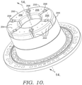
FIG. 10 is a perspective view of a portion of a gas turbine combustor in accordance with an alternate embodiment which is not part of the present invention. -
FIG. 11 is an alternate perspective view of a portion of the gas turbine combustor in accordance with the alternate embodiment - not part of the present invention - ofFIG. 10 . -
FIG. 12 an end view of a portion of the gas turbine combustor ofFIG. 10 in accordance with an alternate embodiment which is not part of the present invention. -
FIG. 13 is an opposing end view of the gas turbine combustor ofFIG. 10 in accordance with an alternate embodiment which is not part of the present invention. -
FIG. 14 is a cross section of the gas turbine combustor ofFIG. 10 in accordance with an alternate embodiment which is not part of the present invention. -
FIG. 15 is a detailed cross section view of a damper portion of the portion of the gas turbine combustor ofFIG. 14 in accordance with an alternate embodiment which is not part of the present invention. -
FIG. 16 is a detailed cross section view of a damper portion of the gas turbine combustor in accordance with an embodiment of the present invention. -
FIG. 17 is a partial perspective view of a damper portion and dome plate region of the gas turbine combustor ofFIG. 16 in accordance with an alternate embodiment of the present invention. -
FIG. 18 is a detailed cross section view of a damper portion of the gas turbine combustor in accordance with an additional embodiment of the present invention. -
FIG. 19 is a partial perspective view of a damper portion and dome plate region of the gas turbine combustor ofFIG. 18 in accordance with an additional embodiment of the present invention. -
FIG. 20 is a perspective view of a portion of a gas turbine combustor in accordance with an alternate damper support configuration of the present invention. -
FIG. 21 is a perspective view of a portion of the gas turbine combustor configuration ofFIG. 20 . -
FIG. 22 is a detailed perspective view of the damper portion of the gas turbine combustor ofFIG. 21 . -
FIG. 23 is a cross section view of the damper portion of the gas turbine combustor ofFIG 21 . -
FIG. 24 is a perspective view of a forward face of an adapter plate in accordance with an embodiment of the present invention. -
FIG. 25 is a perspective view of an aft face of the adapter plate ofFIG. 24 in accordance with an embodiment of the present invention. -
FIG. 26 is a flow diagram outlining a method of regulating combustor dynamics. - The present invention discloses a dome assembly for gas turbine combustion system for use in a premix combustion system to help reduce combustion dynamics and is shown in detail in
FIGS. 16-25 . As one skilled in the art understands, a gas turbine engine typically incorporates a plurality of combustors. Generally, for the purpose of discussion, the gas turbine engine may include low emission combustors such as those disclosed herein and may be arranged in a can-annular configuration about the gas turbine engine. One type of gas turbine engine (e.g., heavy duty gas turbine engines) may be typically provided with, but not limited to, six to eighteen individual combustors, each of them fitted with the components outlined above. Accordingly, based on the type of gas turbine engine, there may be several different fuel circuits utilized for operating the gas turbine engine. - Referring specifically to
FIG. 1 , a gasturbine combustion system 100 is shown in cross section. The gasturbine combustion system 100 comprises a generally cylindrical combustion liner 102 having a central axis A-A and located coaxial to and radially within aflow sleeve 104. The combustion liner 102 has aninlet end 106 and anopposing outlet end 108. - The gas
turbine combustion system 100 also comprises a set ofmain fuel injectors 110 positioned radially outward of the combustion liner 102 and proximate an upstream end of theflow sleeve 104. Thecombustion system 100 disclosed inFIG. 1 is a multi-stage premixing combustion system comprising four stages of fuel injection based on the loading of the engine. However, it is envisioned that the specific fuel circuitry and associated control mechanisms could be modified to include fewer or additional fuel circuits. - For the example shown in
FIG. 1 , themain fuel injectors 110 are located radially outward of the combustion liner 102 and spread in an annular array about the combustion liner 102. Themain fuel injectors 110 are divided into two stages with a first stage extending approximately 120 degrees about the combustion liner 102 and a second stage extending the remaining annular portion, or approximately 240 degrees, about the combustion liner 102. The first stage of themain fuel injectors 110 are used to generate a Main 1 flame in combustion liner 102 while the second stage of themain fuel injectors 110 generate a Main 2 flame in the combustion liner. - The gas turbine combustion system also comprises a
combustor dome assembly 112 that encompasses theinlet end 106 of the combustion liner 102. Thecombustor dome assembly 112 extends from proximate the set ofmain fuel injectors 110 to adome plate 114, where thedome plate 114 has a generally hemispherical-shaped cross section with thedome plate 114 positioned a distance forward of theinlet end 106 of the combustion liner 102 and turning to extend a distance into the combustion liner 102. The shape of the combustor dome assembly can also be seen inFIG. 6 . Referring now toFIGS. 2-9 , thecombustor dome assembly 112 comprises a plurality ofopenings 116 in thedome plate 114, where each of theopenings 116 has a diameter D and a neck length L. Preferably, theopenings 116 have a circular cross section, but other shapes are also possible. Theopenings 116 are oriented in thedome plate 114 so as to preferably be parallel with a central axis A-A of thecombustion system 100. Extending away from thedome plate 114, opposite of the combustion liner, is a plurality ofdome dampers 118. Referring toFIG. 8 , each of thedome dampers 118 encompasses one of theopenings 116 and comprises adamper body 120 having an opening located therein. Accordingly, for thedome plate 114, thedome dampers 118 are oriented in an annular array about the central axis A-A of thecombustion system 100. Aremovable cover plate 122 is secured to an end of thedamper body 120 opposite of theopening 116 to form adamper volume 124. Thedamper body 120 also includes a plurality of purge holes 126. - The
dome dampers 118 extend away from the combustion liner 102 in a way to establish predetermined volumes of air in order to provide a volume of air sufficient to dampen pressure fluctuations within the combustion liner 102. Thedome dampers 118 are supplied with compressed air by way of purge holes 126, which, in an example are located along a side of thedamper body 120 and are sized both in diameter and quantity to ensure a sufficient volume of compressed air is provided to thedamper volume 124. The exact location and spacing of the purge holes 126 can vary. That is, the purge holes 126 may be located about thedamper body 120 or thecover plate 122. - In operation, a pressure wave from the combustor travels upstream towards the
dome plate 114, passes through theopenings 116 in thedome plate 114, and into thedamper volume 124 formed by thedamper body 120 andcover plate 122. Once in thedamper volume 124, the wave then encounters the volume of compressed air. The extra volume of air serves to generate a wave that is out of phase with an incoming wave, similar to how a spring and shock operate to counteract the movement of a motor vehicle. That is, the volume of air in the damper counteracts the pressure wave traveling up through the combustor. - As discussed above, the
dome dampers 118 andcorresponding damper volume 124 are sized to specifically target a particular resonance frequency for the damper in order to counteract a specific frequency or pressure oscillation in the combustion system. As one skilled in the art understands, the basic formula for resonance frequency of a damper is fres=c/2/π∗sqrt(Aneck/Lneck,eff/Vdamper), where fres is the resonance frequency of the damper, c is the speed of sound, Aneck is the cross sectional area of theopening 116 connecting the damping volume to the combustor, Lneck,eff is the effective length L of theopening 116 and Vdamper is volume of the damper. Therefore, altering the cross sectional area ofopening 116, its length L and thevolume 124 can each affect the resonance frequency for the damper. For example, decreasing the volume of the damper increases the damper resonance frequency, while increasing the volume of the damper lowers the damper resonance frequency. Furthermore, the length L of theopening 116, or "neck" of the opening, can also vary. That is, if the length L of the neck region is increased, the resonance frequency of the damper decreases and if the length L of the neck region is decreased, the resonance frequency of the damper increases. A final variable for determining the resonance frequency of the damper is the area of theopening 116. If the area ofopening 116 is increased, through a larger diameter D, the resonance frequency of the damper increases, whereas if the area ofopening 116 is decreased, through a smaller diameter D, the resonance frequency of the damper decreases. Therefore, depending on the frequency one is trying to dampen, various elements on the damper can be modified to target one or more specific frequencies. - As for the frequencies being targeted by a dome damper structure, in premix style combustions systems, such as that shown in
FIG. 1 , high frequencies (screech) in the range of 1-10kHz are typically of high concern. However, lower frequencies, in the range of 50-500Hz can also be targeted. When targeting screech, or high frequencies, typical damper dimensions include a neck length L of approximately 5mm - 25mm and a neck diameter D of approximately 5mm - 15mm. When targeting lower frequencies, a typical neck length L is longer, on the order of approximately 20mm - 200mm while the neck diameter D is approximately 10mm - 100mm. As such, one way to express these geometric requirements is through a ratio of diameter D to neck length L, which, for example, is approximately 0.2 to 2.0. - With respect to the purge holes 126, the equivalent area of all of the purge holes 126 define the total mass flow through the damper, and therefore, the velocity in the neck, which in turn defines the damping properties. The total area of the purge holes 126 is generally small compared to the area of the
opening 116, or Aneck, such that the majority of the pressure drop across the damper is generated at the purge holes 126. For example, the total area of all of the purge holes 126 are approximately 10% or less than the Aneck (or area of the opening 116). For the example depicted inFIGS 1-9 , and specifically referring toFIGS. 7-9 , each of thedamper bodies 120 have six purge holes 126. More purge holes 126 are typically required for higher velocity flow. - As discussed above, there are three major variables which can be adjusted to adjust the resonance frequency of the damper - area of the neck (hence diameter D), length of the neck (length L) and volume of the damper. However, as a practical point, not all of these variables can be changed once the hardware has been manufactured in the event during operation, it is determined that a different frequency of the combustor should be dampened. For example, it is difficult to change the size of the
openings 116 and the length L of the openings on completed combustion systems. However, one such variable that can be modified is the volume of the damper. For the configuration depicted inFIGS. 2 ,4 , and6-8 , thedamper volume 124 can be modified by way of aremovable coverplate 122, or plug-like plate. Theremovable coverplate 122 is secured todamper body 120 by aremovable fastener 128, such as a snap ring, clip, threaded body, or a bolt. This fastening mechanism provides an easy way to remove thecoverplate 122 and replace it with a coverplate of a different size, resulting in adifferent damper volume 124. In order to ease the process of exchangingcoverplates 122, each coverplate typically has arecess pocket 130 in which a tool can be placed to help remove thecoverplate 122. Thereafter anew coverplate 122 can be put in place and then secured to one or more of thedamper bodies 120. - The
damper bodies 120 shown inFIGS. 1-9 are generally cylindrical and oriented in an annular array about a center axis, as shown inFIGS. 2 and4 . However, dampers are not limited to the cylindrical configuration, and in fact, can take on generally any shape and quantity, as required. An alternate example is shown in detail inFIGS. 10-15 . In this alternate example, one ormore resonator boxes 200 are secured over the dome plate andopening 202. The size of opening 202 (diameter and neck length) is controlled by a threadedinsert 203, as shown inFIGS. 14 and15 . The neck length and diameter may be controlled by a single threaded insert. Theresonator boxes 200 provide a larger volume than the smaller cylindrical-shaped dampers as depicted inFIGS. 1-9 . For the similar combustion system ofFIGS. 1-9 , instead of twenty-four cylindrical dampers, there are instead six resonator boxes employed. However, it is envisioned that the number of cylindrical dampers and resonator boxes may be modified to include fewer or additional dampers or boxes. Similar to thecylindrical damper bodies 120, theresonator boxes 200 also includepurges holes 204 for supplying compressed air into theresonator box 200. As discussed above, the placement of purge holes 204 can also vary about theresonator 200 and/or thecoverplate 206. Unlike the cylindrical damper body of the prior configuration, thecoverplate 206 of theresonator box 200 is preferably fastened to theresonator box 200 by a means such as abolt 208. - Similar to the cylindrical damper bodies, the three factors that can also change the resonator frequency of a
resonator box 200 are the area of the neck (hence diameter D), length of the neck (length L) and volume of the resonator box. However, if during operation it is determined that a different frequency should be dampened, not all of these variables can be changed once the hardware has been manufactured. One variable that can be modified relatively easily, post-manufacturing, is the volume of the resonator box. Thecoverplate 206 can be removed and replaced with a different size coverplate that, due to its thickness, either increases or decreases the volume in theresonator box 200. - In an alternate example, various combinations of the damping mechanisms discussed above can be utilized together. For example, it is possible to employ a
dome damper 118 positioned within aresonator box 200. Alternatively, it is possible to use theresonator box 200 with a simple opening in the dome (i.e. no separate damper body). - The damper bodies discussed above are depicted generally coaxial to the central axis A-A. However, the
dome damper 118 and/orresonator box 200 can also be oriented at an angle relative to the central axis A-A. Where such damper bodies are angled, so are the correspondingopenings - In yet another example it is possible to target multiple critical frequencies in the combustion system through dampers configured to counteract more than one critical frequency. For example, a combustor can have a first set of dampers having a first opening diameter, area, volume and neck length directed towards targeting a first frequency, and a second set of dampers, having a second opening diameter, area, volume and neck length directed towards targeting a different frequency than the first set of dampers. The quantity of the first set of dampers and second set of dampers can vary as required.
- In the examples discussed above, a basic geometry for the damper was a single volume with one neck length and effective area are disclosed. However, it is envisioned that more complex geometries for the damper bodies can be utilized in the present invention. For example, in another example, multiple frequencies can be targeted by way of a damper body having multiple volumes arranged in an axial series, where a series of volumes and necks form a multi-volume damper.
- As discussed above, without damper mechanisms in place on a premix combustor disclosed in
FIG. 1 , the operation of the premix combustor is limited. For example, for a combustion system similar to that ofFIG. 1 , normal combustion dynamics of 0.5psi fluctuation could be tolerated by combustion hardware. By implementing a damper system disclosed herein, greater pressure fluctuations (increased combustion dynamics) can be tolerated, including pressure fluctuations upwards of approximately 1 psi. The damper system helps to reduce the adverse effects of the combustion dynamics by reducing the impact of critical vibration levels. - An embodiment of the present invention is disclosed in
FIGS. 16-25 . As discussed above, the plurality ofdamper bodies 120 andresonator boxes 200 are mounted to thedome plate 114. However, thedome plate 114 has a curved surface, which can present difficulty when mounting this hardware. Furthermore, such combustor construction can also be quite costly to manufacture due to the complex geometries. - An additional feature that may be included in an embodiment of the present invention is an
adapter plate 300 which is positioned between theresonator box 200 ordome dampers 118 and thedome plate 114. Theadapter plate 300 has the same general configuration and function, whether it is used in conjunction with a resonator box or a damper body - to provide an improved way of mounting and securing the dampers to thedomeplate 114 of the combustor. - Referring to
FIGS. 16-19 , theadapter plate 300 is shown with respect to an embodiment of the present invention featuring a plurality ofindividual dome dampers 118. Theadapter plate 300 comprises aforward face 302 and anaft face 304 spaced a distance from theforward face 302 and parallel to theforward face 302. Theadapter plate 300 is secured to thedome plate 114 by a plurality of fasteners or can be permanently fixed to thedomeplate 114 by way of welding or brazing. - The
adapter plate 300 also comprises a first plurality ofplate openings 306. Theseopenings 306 correspond to theopenings 116 in thedomeplate 114 such that thedamper volume 124 is in communication with the combustor volume inside thedomeplate 114. Extending from theforward face 302 of theadapter plate 300 are a plurality ofdome dampers 118. Thedome dampers 118 can be integral to theadapter plate 300 or separately attached, such as through braze or welding, to theadapter plate 300. Thedome dampers 118 can be mounted perpendicular to theadapter plate 300 as shown inFIGS. 16 and17 or thedome dampers 118 can be mounted at an angle relative to thedome dampers 118, as shown inFIGS. 18 and19 . - In another version of the present invention, the
adapter plate 300 can take on a slightly different configuration as shown inFIGS. 24 and 25 . More specifically, theadapter plate 300 has afront face 312 and an opposingaft face 314. Theaft face 314 includes a contouredportion 308 that is sized and shaped to mate to the curved profile of thedomeplate 114. - The alternate version of the
adapter plate 300 can be seen in use with an alternate dome damper configuration, theresonator box 200, as shown inFIGS. 20-23 . Referring toFIGS. 20-23 , a combustor dome assembly incorporating theresonator boxes 200, similar to that ofFIGS. 10-15 is disclosed. However, for the embodiment shown inFIGS. 20-23 , theresonator boxes 200 are mounted to thedomeplate 114 through theadapter plate 300, previously discussed and shown inFIGS. 24 and 25 . More specifically, theadapter plate 300 shown inFIGS. 24 and 25 includes a first plurality ofplate openings 310 through which the damper bodies / volume communicates with the combustor. Theadapter plate 300 also includes a second plurality ofplate openings 315. Theadapter plate 300 also includes a third plurality ofopenings 318 spaced in an annular array about theadapter plate 300. The third plurality ofopenings 318 each include afastener 320 secured to theadapter plate 300, where thefastener 320 is used to secured the one ormore resonator boxes 200 to theadapter plate 300, as shown inFIG. 22 . - The
dome dampers 324 can extend generally perpendicular to theadapter plate 300. Alternatively, and as shown inFIGS. 22 and 23 , thedome dampers 324 can also be oriented at an angle relative to theadapter plate 300. Whetherresonator boxes 200 ordome dampers 118 are being used, theadapter plate 300 provides an improved way of securing and locating damper configurations to thedomeplate 114. - Referring to
FIG. 26 , amethod 2600 of regulating combustion dynamics in a gas turbine combustor is disclosed. In astep 2602, a combustion system is provided having a combustor dome assembly comprising a dome plate with a plurality of openings in the dome plate, where each of the openings has a diameter and neck length. The combustion system also includes a plurality of dome dampers encompassing respective openings in the dome plate. In astep 2604, one or more desired combustion frequencies to control is determined. As discussed above, the frequency to be controlled can be a high frequency, such as screech, or a lower frequency. In a step 2606 a desired volume for the dome dampers necessary to target the one or more frequencies identified instep 2604 is determined. Then, in astep 2608, a desired amount of purge air to flow into the dome dampers is determined. In astep 2610, a coverplate is secured to at least an end of the dome dampers where the coverplate is placed in a position to form the desired volume for the dampers determined instep 2606. Then, in astep 2612, a determination is made as to whether the desired volume of each damper determined instep 2606 is sufficient to alter the combustor frequency. Such a determination is typically made as a result of operating the combustion system. If the determination is made that the damper volume is insufficient, then in astep 2614, one or more variables affecting the resonance frequency of the damper, such as neck length, opening diameter or damper volume are determined to be changed and the process returns to step 2606 to determine the desired damper volume. If a determination is made atstep 2612 that the desired damper volume is sufficient to dampen the desired combustion frequency, then the process ends at astep 2616. - While the invention has been described in what is known as presently the preferred embodiment, it is to be understood that the invention is not to be limited to the disclosed embodiment but, on the contrary, is intended to cover various modifications and equivalent arrangements within the scope of the following claims. The present invention has been described in relation to particular embodiments, which are intended in all respects to be illustrative rather than restrictive.
Claims (6)
- A dome assembly for a gas turbine combustion system comprising:a dome plate (114) having a generally hemispherically-shaped cross section, the dome plate (114) comprising an inlet to a combustion liner (102) and having a plurality of openings (116) therein, each opening (116) having a first diameter;the dome assembly being characterized in further comprising:an adapter plate (300) positioned adjacent to the dome plate (114) comprising:a forward face (302);an aft face (304);a first plurality of plate openings (306) in the adapter plate (300);a second plurality of plate openings (315) in the adapter plate (300);one or more resonator boxes (200) extending from the adapter plate (300) and encompassing one or more of the first plurality of plate openings (306) in the dome plate (114);a plurality of dome dampers (324) extending from the adapter plate (300) and into the one or more resonator boxes (200), each of the dome dampers (324) positioned within one of the first plurality of plate openings (306) in the dome plate (114).
- The dome assembly of claim 1, wherein each of the dome dampers (324) extends through an opening in the adapter plate (300) and an opening in the dome plate (114).
- The dome assembly of claim 1, wherein the adapter plate (300) is removably secured to the dome plate (114).
- The dome assembly of claim 1, wherein the adapter plate (300) further comprises a contoured portion in the aft face (304) for mating the adapter plate (300) to the dome plate (114).
- The dome assembly of claim 1, wherein the adapter plate (300) comprises a third plurality of openings (318) spaced in an annular array.
- The dome assembly of claim 5, wherein each of the third plurality of openings (318) includes a fastener (320) secured to the adapter plate (300); wherein the fastener (320) is used to secure the one or more resonator boxes (200) to the adapter plate (300).
Applications Claiming Priority (3)
| Application Number | Priority Date | Filing Date | Title |
|---|---|---|---|
| US14/486,289 US10267523B2 (en) | 2014-09-15 | 2014-09-15 | Combustor dome damper system |
| PCT/US2015/049919 WO2016044135A1 (en) | 2014-09-15 | 2015-09-14 | Combustor dome damper system |
| EP15767064.7A EP3194851B1 (en) | 2014-09-15 | 2015-09-14 | Combustor dome damper system |
Related Parent Applications (2)
| Application Number | Title | Priority Date | Filing Date |
|---|---|---|---|
| EP15767064.7A Division EP3194851B1 (en) | 2014-09-15 | 2015-09-14 | Combustor dome damper system |
| EP15767064.7A Division-Into EP3194851B1 (en) | 2014-09-15 | 2015-09-14 | Combustor dome damper system |
Publications (2)
| Publication Number | Publication Date |
|---|---|
| EP3767177A1 EP3767177A1 (en) | 2021-01-20 |
| EP3767177B1 true EP3767177B1 (en) | 2022-03-09 |
Family
ID=54150763
Family Applications (2)
| Application Number | Title | Priority Date | Filing Date |
|---|---|---|---|
| EP15767064.7A Active EP3194851B1 (en) | 2014-09-15 | 2015-09-14 | Combustor dome damper system |
| EP20194863.5A Not-in-force EP3767177B1 (en) | 2014-09-15 | 2015-09-14 | Combustor dome damper system |
Family Applications Before (1)
| Application Number | Title | Priority Date | Filing Date |
|---|---|---|---|
| EP15767064.7A Active EP3194851B1 (en) | 2014-09-15 | 2015-09-14 | Combustor dome damper system |
Country Status (6)
| Country | Link |
|---|---|
| US (1) | US10267523B2 (en) |
| EP (2) | EP3194851B1 (en) |
| JP (1) | JP6631999B2 (en) |
| KR (1) | KR102448663B1 (en) |
| CN (1) | CN107003002B (en) |
| WO (1) | WO2016044135A1 (en) |
Families Citing this family (14)
| Publication number | Priority date | Publication date | Assignee | Title |
|---|---|---|---|---|
| US10316746B2 (en) * | 2015-02-04 | 2019-06-11 | General Electric Company | Turbine system with exhaust gas recirculation, separation and extraction |
| EP3299721B1 (en) * | 2016-09-22 | 2020-09-02 | Ansaldo Energia Switzerland AG | Annular helmholtz damper for a gas turbine can combustor |
| US10724739B2 (en) * | 2017-03-24 | 2020-07-28 | General Electric Company | Combustor acoustic damping structure |
| US10415480B2 (en) | 2017-04-13 | 2019-09-17 | General Electric Company | Gas turbine engine fuel manifold damper and method of dynamics attenuation |
| US10941939B2 (en) | 2017-09-25 | 2021-03-09 | General Electric Company | Gas turbine assemblies and methods |
| US11156162B2 (en) | 2018-05-23 | 2021-10-26 | General Electric Company | Fluid manifold damper for gas turbine engine |
| US11506125B2 (en) | 2018-08-01 | 2022-11-22 | General Electric Company | Fluid manifold assembly for gas turbine engine |
| JP2020056542A (en) * | 2018-10-02 | 2020-04-09 | 川崎重工業株式会社 | Annular type gas turbine combustor for aircraft |
| US11156164B2 (en) | 2019-05-21 | 2021-10-26 | General Electric Company | System and method for high frequency accoustic dampers with caps |
| US11174792B2 (en) | 2019-05-21 | 2021-11-16 | General Electric Company | System and method for high frequency acoustic dampers with baffles |
| US11371699B2 (en) * | 2019-11-12 | 2022-06-28 | General Electric Company | Integrated front panel for a burner |
| US11686474B2 (en) * | 2021-03-04 | 2023-06-27 | General Electric Company | Damper for swirl-cup combustors |
| US11859819B2 (en) | 2021-10-15 | 2024-01-02 | General Electric Company | Ceramic composite combustor dome and liners |
| CN116928696A (en) * | 2022-03-31 | 2023-10-24 | 通用电气公司 | Liner assembly for a combustor |
Citations (1)
| Publication number | Priority date | Publication date | Assignee | Title |
|---|---|---|---|---|
| EP1596130B1 (en) * | 2004-05-14 | 2014-12-31 | Siemens Aktiengesellschaft | Device for damping thermoacoustic oscillations in a combustion chamber with a variable resonator frequency |
Family Cites Families (17)
| Publication number | Priority date | Publication date | Assignee | Title |
|---|---|---|---|---|
| EP0597138B1 (en) * | 1992-11-09 | 1997-07-16 | Asea Brown Boveri AG | Combustion chamber for gas turbine |
| US5644918A (en) * | 1994-11-14 | 1997-07-08 | General Electric Company | Dynamics free low emissions gas turbine combustor |
| WO2004051063A1 (en) * | 2002-12-02 | 2004-06-17 | Mitsubishi Heavy Industries, Ltd. | Gas turbine combustor, and gas turbine with the combustor |
| ITTO20031013A1 (en) * | 2003-12-16 | 2005-06-17 | Ansaldo Energia Spa | THERMO ACOUSTIC INSTABILITY DAMPING SYSTEM IN A COMBUSTOR DEVICE FOR A GAS TURBINE. |
| US7513115B2 (en) * | 2005-05-23 | 2009-04-07 | Power Systems Mfg., Llc | Flashback suppression system for a gas turbine combustor |
| GB0610800D0 (en) * | 2006-06-01 | 2006-07-12 | Rolls Royce Plc | Combustion chamber for a gas turbine engine |
| US8127546B2 (en) * | 2007-05-31 | 2012-03-06 | Solar Turbines Inc. | Turbine engine fuel injector with helmholtz resonators |
| US9262403B2 (en) * | 2009-03-02 | 2016-02-16 | Sdl Plc | Dynamic generation of auto-suggest dictionary for natural language translation |
| US8408004B2 (en) * | 2009-06-16 | 2013-04-02 | General Electric Company | Resonator assembly for mitigating dynamics in gas turbines |
| EP2299177A1 (en) * | 2009-09-21 | 2011-03-23 | Alstom Technology Ltd | Combustor of a gas turbine |
| US8413443B2 (en) * | 2009-12-15 | 2013-04-09 | Siemens Energy, Inc. | Flow control through a resonator system of gas turbine combustor |
| CH702594A1 (en) * | 2010-01-28 | 2011-07-29 | Alstom Technology Ltd | Helmholtz damper for incorporation in the combustor of a gas turbine and method of installation of such a Helmholtz damper. |
| EP2397759A1 (en) | 2010-06-16 | 2011-12-21 | Alstom Technology Ltd | Damper Arrangement |
| CN103842727A (en) * | 2011-09-22 | 2014-06-04 | 通用电气公司 | Combustor cap for damping low frequency dynamics |
| US9212823B2 (en) | 2012-09-06 | 2015-12-15 | General Electric Company | Systems and methods for suppressing combustion driven pressure fluctuations with a premix combustor having multiple premix times |
| US8684130B1 (en) | 2012-09-10 | 2014-04-01 | Alstom Technology Ltd. | Damping system for combustor |
| US9347669B2 (en) * | 2012-10-01 | 2016-05-24 | Alstom Technology Ltd. | Variable length combustor dome extension for improved operability |
-
2014
- 2014-09-15 US US14/486,289 patent/US10267523B2/en active Active
-
2015
- 2015-09-14 KR KR1020177008731A patent/KR102448663B1/en active IP Right Grant
- 2015-09-14 EP EP15767064.7A patent/EP3194851B1/en active Active
- 2015-09-14 CN CN201580061884.4A patent/CN107003002B/en active Active
- 2015-09-14 JP JP2017514672A patent/JP6631999B2/en active Active
- 2015-09-14 EP EP20194863.5A patent/EP3767177B1/en not_active Not-in-force
- 2015-09-14 WO PCT/US2015/049919 patent/WO2016044135A1/en active Application Filing
Patent Citations (1)
| Publication number | Priority date | Publication date | Assignee | Title |
|---|---|---|---|---|
| EP1596130B1 (en) * | 2004-05-14 | 2014-12-31 | Siemens Aktiengesellschaft | Device for damping thermoacoustic oscillations in a combustion chamber with a variable resonator frequency |
Also Published As
| Publication number | Publication date |
|---|---|
| CN107003002B (en) | 2020-02-07 |
| WO2016044135A1 (en) | 2016-03-24 |
| CN107003002A (en) | 2017-08-01 |
| EP3767177A1 (en) | 2021-01-20 |
| KR20170055496A (en) | 2017-05-19 |
| US10267523B2 (en) | 2019-04-23 |
| JP6631999B2 (en) | 2020-01-15 |
| EP3194851A1 (en) | 2017-07-26 |
| US20160076772A1 (en) | 2016-03-17 |
| JP2017533375A (en) | 2017-11-09 |
| KR102448663B1 (en) | 2022-09-29 |
| EP3194851B1 (en) | 2020-12-30 |
Similar Documents
| Publication | Publication Date | Title |
|---|---|---|
| EP3767177B1 (en) | Combustor dome damper system | |
| US7827797B2 (en) | Injection assembly for a combustor | |
| US9255711B2 (en) | System for reducing combustion dynamics by varying fuel flow axial distances | |
| US9032704B2 (en) | System for reducing combustion dynamics | |
| US7631500B2 (en) | Methods and apparatus to facilitate decreasing combustor acoustics | |
| US10718525B2 (en) | Fuel injection locations based on combustor flow path | |
| US9714768B2 (en) | Systems and apparatus relating to downstream fuel and air injection in gas turbines | |
| US8631656B2 (en) | Gas turbine engine combustor circumferential acoustic reduction using flame temperature nonuniformities | |
| US20100263382A1 (en) | Dual orifice pilot fuel injector | |
| US20150219336A1 (en) | Systems and methods for reducing modal coupling of combustion dynamics | |
| US9435541B2 (en) | Systems and apparatus relating to downstream fuel and air injection in gas turbines | |
| EP3775694B1 (en) | Premixer for low emissions gas turbine combustor | |
| US20140260270A1 (en) | Systems and apparatus relating to downstream fuel and air injection in gas turbines | |
| US9644845B2 (en) | System and method for reducing modal coupling of combustion dynamics | |
| EP3317585B1 (en) | Fuel cartridge assembly for a gas turbine | |
| US11940151B2 (en) | Combustor with baffle | |
| US20240263786A1 (en) | Central air passage with radial fuel distributor |
Legal Events
| Date | Code | Title | Description |
|---|---|---|---|
| PUAI | Public reference made under article 153(3) epc to a published international application that has entered the european phase |
Free format text: ORIGINAL CODE: 0009012 |
|
| STAA | Information on the status of an ep patent application or granted ep patent |
Free format text: STATUS: THE APPLICATION HAS BEEN PUBLISHED |
|
| AC | Divisional application: reference to earlier application |
Ref document number: 3194851 Country of ref document: EP Kind code of ref document: P |
|
| AK | Designated contracting states |
Kind code of ref document: A1 Designated state(s): AL AT BE BG CH CY CZ DE DK EE ES FI FR GB GR HR HU IE IS IT LI LT LU LV MC MK MT NL NO PL PT RO RS SE SI SK SM TR |
|
| STAA | Information on the status of an ep patent application or granted ep patent |
Free format text: STATUS: REQUEST FOR EXAMINATION WAS MADE |
|
| 17P | Request for examination filed |
Effective date: 20210512 |
|
| RBV | Designated contracting states (corrected) |
Designated state(s): AL AT BE BG CH CY CZ DE DK EE ES FI FR GB GR HR HU IE IS IT LI LT LU LV MC MK MT NL NO PL PT RO RS SE SI SK SM TR |
|
| RAP1 | Party data changed (applicant data changed or rights of an application transferred) |
Owner name: H2 IP UK LIMITED |
|
| GRAP | Despatch of communication of intention to grant a patent |
Free format text: ORIGINAL CODE: EPIDOSNIGR1 |
|
| STAA | Information on the status of an ep patent application or granted ep patent |
Free format text: STATUS: GRANT OF PATENT IS INTENDED |
|
| INTG | Intention to grant announced |
Effective date: 20210929 |
|
| GRAS | Grant fee paid |
Free format text: ORIGINAL CODE: EPIDOSNIGR3 |
|
| GRAA | (expected) grant |
Free format text: ORIGINAL CODE: 0009210 |
|
| STAA | Information on the status of an ep patent application or granted ep patent |
Free format text: STATUS: THE PATENT HAS BEEN GRANTED |
|
| AC | Divisional application: reference to earlier application |
Ref document number: 3194851 Country of ref document: EP Kind code of ref document: P |
|
| AK | Designated contracting states |
Kind code of ref document: B1 Designated state(s): AL AT BE BG CH CY CZ DE DK EE ES FI FR GB GR HR HU IE IS IT LI LT LU LV MC MK MT NL NO PL PT RO RS SE SI SK SM TR |
|
| REG | Reference to a national code |
Ref country code: CH Ref legal event code: EP Ref country code: AT Ref legal event code: REF Ref document number: 1474471 Country of ref document: AT Kind code of ref document: T Effective date: 20220315 |
|
| REG | Reference to a national code |
Ref country code: DE Ref legal event code: R096 Ref document number: 602015077522 Country of ref document: DE |
|
| REG | Reference to a national code |
Ref country code: IE Ref legal event code: FG4D |
|
| REG | Reference to a national code |
Ref country code: NL Ref legal event code: FP |
|
| REG | Reference to a national code |
Ref country code: LT Ref legal event code: MG9D |
|
| PG25 | Lapsed in a contracting state [announced via postgrant information from national office to epo] |
Ref country code: SE Free format text: LAPSE BECAUSE OF FAILURE TO SUBMIT A TRANSLATION OF THE DESCRIPTION OR TO PAY THE FEE WITHIN THE PRESCRIBED TIME-LIMIT Effective date: 20220309 Ref country code: RS Free format text: LAPSE BECAUSE OF FAILURE TO SUBMIT A TRANSLATION OF THE DESCRIPTION OR TO PAY THE FEE WITHIN THE PRESCRIBED TIME-LIMIT Effective date: 20220309 Ref country code: NO Free format text: LAPSE BECAUSE OF FAILURE TO SUBMIT A TRANSLATION OF THE DESCRIPTION OR TO PAY THE FEE WITHIN THE PRESCRIBED TIME-LIMIT Effective date: 20220609 Ref country code: LT Free format text: LAPSE BECAUSE OF FAILURE TO SUBMIT A TRANSLATION OF THE DESCRIPTION OR TO PAY THE FEE WITHIN THE PRESCRIBED TIME-LIMIT Effective date: 20220309 Ref country code: HR Free format text: LAPSE BECAUSE OF FAILURE TO SUBMIT A TRANSLATION OF THE DESCRIPTION OR TO PAY THE FEE WITHIN THE PRESCRIBED TIME-LIMIT Effective date: 20220309 Ref country code: BG Free format text: LAPSE BECAUSE OF FAILURE TO SUBMIT A TRANSLATION OF THE DESCRIPTION OR TO PAY THE FEE WITHIN THE PRESCRIBED TIME-LIMIT Effective date: 20220609 |
|
| REG | Reference to a national code |
Ref country code: AT Ref legal event code: MK05 Ref document number: 1474471 Country of ref document: AT Kind code of ref document: T Effective date: 20220309 |
|
| PG25 | Lapsed in a contracting state [announced via postgrant information from national office to epo] |
Ref country code: LV Free format text: LAPSE BECAUSE OF FAILURE TO SUBMIT A TRANSLATION OF THE DESCRIPTION OR TO PAY THE FEE WITHIN THE PRESCRIBED TIME-LIMIT Effective date: 20220309 Ref country code: GR Free format text: LAPSE BECAUSE OF FAILURE TO SUBMIT A TRANSLATION OF THE DESCRIPTION OR TO PAY THE FEE WITHIN THE PRESCRIBED TIME-LIMIT Effective date: 20220610 Ref country code: FI Free format text: LAPSE BECAUSE OF FAILURE TO SUBMIT A TRANSLATION OF THE DESCRIPTION OR TO PAY THE FEE WITHIN THE PRESCRIBED TIME-LIMIT Effective date: 20220309 |
|
| PG25 | Lapsed in a contracting state [announced via postgrant information from national office to epo] |
Ref country code: SM Free format text: LAPSE BECAUSE OF FAILURE TO SUBMIT A TRANSLATION OF THE DESCRIPTION OR TO PAY THE FEE WITHIN THE PRESCRIBED TIME-LIMIT Effective date: 20220309 Ref country code: SK Free format text: LAPSE BECAUSE OF FAILURE TO SUBMIT A TRANSLATION OF THE DESCRIPTION OR TO PAY THE FEE WITHIN THE PRESCRIBED TIME-LIMIT Effective date: 20220309 Ref country code: RO Free format text: LAPSE BECAUSE OF FAILURE TO SUBMIT A TRANSLATION OF THE DESCRIPTION OR TO PAY THE FEE WITHIN THE PRESCRIBED TIME-LIMIT Effective date: 20220309 Ref country code: PT Free format text: LAPSE BECAUSE OF FAILURE TO SUBMIT A TRANSLATION OF THE DESCRIPTION OR TO PAY THE FEE WITHIN THE PRESCRIBED TIME-LIMIT Effective date: 20220711 Ref country code: ES Free format text: LAPSE BECAUSE OF FAILURE TO SUBMIT A TRANSLATION OF THE DESCRIPTION OR TO PAY THE FEE WITHIN THE PRESCRIBED TIME-LIMIT Effective date: 20220309 Ref country code: EE Free format text: LAPSE BECAUSE OF FAILURE TO SUBMIT A TRANSLATION OF THE DESCRIPTION OR TO PAY THE FEE WITHIN THE PRESCRIBED TIME-LIMIT Effective date: 20220309 Ref country code: CZ Free format text: LAPSE BECAUSE OF FAILURE TO SUBMIT A TRANSLATION OF THE DESCRIPTION OR TO PAY THE FEE WITHIN THE PRESCRIBED TIME-LIMIT Effective date: 20220309 Ref country code: AT Free format text: LAPSE BECAUSE OF FAILURE TO SUBMIT A TRANSLATION OF THE DESCRIPTION OR TO PAY THE FEE WITHIN THE PRESCRIBED TIME-LIMIT Effective date: 20220309 |
|
| PG25 | Lapsed in a contracting state [announced via postgrant information from national office to epo] |
Ref country code: PL Free format text: LAPSE BECAUSE OF FAILURE TO SUBMIT A TRANSLATION OF THE DESCRIPTION OR TO PAY THE FEE WITHIN THE PRESCRIBED TIME-LIMIT Effective date: 20220309 Ref country code: IS Free format text: LAPSE BECAUSE OF FAILURE TO SUBMIT A TRANSLATION OF THE DESCRIPTION OR TO PAY THE FEE WITHIN THE PRESCRIBED TIME-LIMIT Effective date: 20220709 Ref country code: AL Free format text: LAPSE BECAUSE OF FAILURE TO SUBMIT A TRANSLATION OF THE DESCRIPTION OR TO PAY THE FEE WITHIN THE PRESCRIBED TIME-LIMIT Effective date: 20220309 |
|
| REG | Reference to a national code |
Ref country code: DE Ref legal event code: R097 Ref document number: 602015077522 Country of ref document: DE |
|
| PLBE | No opposition filed within time limit |
Free format text: ORIGINAL CODE: 0009261 |
|
| STAA | Information on the status of an ep patent application or granted ep patent |
Free format text: STATUS: NO OPPOSITION FILED WITHIN TIME LIMIT |
|
| PG25 | Lapsed in a contracting state [announced via postgrant information from national office to epo] |
Ref country code: DK Free format text: LAPSE BECAUSE OF FAILURE TO SUBMIT A TRANSLATION OF THE DESCRIPTION OR TO PAY THE FEE WITHIN THE PRESCRIBED TIME-LIMIT Effective date: 20220309 |
|
| 26N | No opposition filed |
Effective date: 20221212 |
|
| PG25 | Lapsed in a contracting state [announced via postgrant information from national office to epo] |
Ref country code: SI Free format text: LAPSE BECAUSE OF FAILURE TO SUBMIT A TRANSLATION OF THE DESCRIPTION OR TO PAY THE FEE WITHIN THE PRESCRIBED TIME-LIMIT Effective date: 20220309 |
|
| REG | Reference to a national code |
Ref country code: DE Ref legal event code: R119 Ref document number: 602015077522 Country of ref document: DE |
|
| PG25 | Lapsed in a contracting state [announced via postgrant information from national office to epo] |
Ref country code: MC Free format text: LAPSE BECAUSE OF FAILURE TO SUBMIT A TRANSLATION OF THE DESCRIPTION OR TO PAY THE FEE WITHIN THE PRESCRIBED TIME-LIMIT Effective date: 20220309 |
|
| REG | Reference to a national code |
Ref country code: CH Ref legal event code: PL |
|
| REG | Reference to a national code |
Ref country code: NL Ref legal event code: MM Effective date: 20221001 |
|
| GBPC | Gb: european patent ceased through non-payment of renewal fee |
Effective date: 20220914 |
|
| REG | Reference to a national code |
Ref country code: BE Ref legal event code: MM Effective date: 20220930 |
|
| PG25 | Lapsed in a contracting state [announced via postgrant information from national office to epo] |
Ref country code: NL Free format text: LAPSE BECAUSE OF NON-PAYMENT OF DUE FEES Effective date: 20221001 Ref country code: LU Free format text: LAPSE BECAUSE OF NON-PAYMENT OF DUE FEES Effective date: 20220914 |
|
| PG25 | Lapsed in a contracting state [announced via postgrant information from national office to epo] |
Ref country code: LI Free format text: LAPSE BECAUSE OF NON-PAYMENT OF DUE FEES Effective date: 20220930 Ref country code: IE Free format text: LAPSE BECAUSE OF NON-PAYMENT OF DUE FEES Effective date: 20220914 Ref country code: FR Free format text: LAPSE BECAUSE OF NON-PAYMENT OF DUE FEES Effective date: 20220930 Ref country code: DE Free format text: LAPSE BECAUSE OF NON-PAYMENT OF DUE FEES Effective date: 20230401 Ref country code: CH Free format text: LAPSE BECAUSE OF NON-PAYMENT OF DUE FEES Effective date: 20220930 |
|
| PG25 | Lapsed in a contracting state [announced via postgrant information from national office to epo] |
Ref country code: BE Free format text: LAPSE BECAUSE OF NON-PAYMENT OF DUE FEES Effective date: 20220930 |
|
| PG25 | Lapsed in a contracting state [announced via postgrant information from national office to epo] |
Ref country code: IT Free format text: LAPSE BECAUSE OF NON-PAYMENT OF DUE FEES Effective date: 20220914 Ref country code: GB Free format text: LAPSE BECAUSE OF NON-PAYMENT OF DUE FEES Effective date: 20220914 |
|
| PG25 | Lapsed in a contracting state [announced via postgrant information from national office to epo] |
Ref country code: CY Free format text: LAPSE BECAUSE OF FAILURE TO SUBMIT A TRANSLATION OF THE DESCRIPTION OR TO PAY THE FEE WITHIN THE PRESCRIBED TIME-LIMIT Effective date: 20220309 |
|
| PG25 | Lapsed in a contracting state [announced via postgrant information from national office to epo] |
Ref country code: MK Free format text: LAPSE BECAUSE OF FAILURE TO SUBMIT A TRANSLATION OF THE DESCRIPTION OR TO PAY THE FEE WITHIN THE PRESCRIBED TIME-LIMIT Effective date: 20220309 Ref country code: HU Free format text: LAPSE BECAUSE OF FAILURE TO SUBMIT A TRANSLATION OF THE DESCRIPTION OR TO PAY THE FEE WITHIN THE PRESCRIBED TIME-LIMIT; INVALID AB INITIO Effective date: 20150914 |
|
| PG25 | Lapsed in a contracting state [announced via postgrant information from national office to epo] |
Ref country code: TR Free format text: LAPSE BECAUSE OF FAILURE TO SUBMIT A TRANSLATION OF THE DESCRIPTION OR TO PAY THE FEE WITHIN THE PRESCRIBED TIME-LIMIT Effective date: 20220309 |
|
| PG25 | Lapsed in a contracting state [announced via postgrant information from national office to epo] |
Ref country code: MT Free format text: LAPSE BECAUSE OF FAILURE TO SUBMIT A TRANSLATION OF THE DESCRIPTION OR TO PAY THE FEE WITHIN THE PRESCRIBED TIME-LIMIT Effective date: 20220309 |