EP3767159A1 - Notlichtleuchte - Google Patents
Notlichtleuchte Download PDFInfo
- Publication number
- EP3767159A1 EP3767159A1 EP20184902.3A EP20184902A EP3767159A1 EP 3767159 A1 EP3767159 A1 EP 3767159A1 EP 20184902 A EP20184902 A EP 20184902A EP 3767159 A1 EP3767159 A1 EP 3767159A1
- Authority
- EP
- European Patent Office
- Prior art keywords
- light
- guide element
- light guide
- illuminants
- groups
- Prior art date
- Legal status (The legal status is an assumption and is not a legal conclusion. Google has not performed a legal analysis and makes no representation as to the accuracy of the status listed.)
- Granted
Links
Images


Classifications
-
- F—MECHANICAL ENGINEERING; LIGHTING; HEATING; WEAPONS; BLASTING
- F21—LIGHTING
- F21S—NON-PORTABLE LIGHTING DEVICES; SYSTEMS THEREOF; VEHICLE LIGHTING DEVICES SPECIALLY ADAPTED FOR VEHICLE EXTERIORS
- F21S9/00—Lighting devices with a built-in power supply; Systems employing lighting devices with a built-in power supply
- F21S9/02—Lighting devices with a built-in power supply; Systems employing lighting devices with a built-in power supply the power supply being a battery or accumulator
- F21S9/022—Emergency lighting devices
-
- F—MECHANICAL ENGINEERING; LIGHTING; HEATING; WEAPONS; BLASTING
- F21—LIGHTING
- F21S—NON-PORTABLE LIGHTING DEVICES; SYSTEMS THEREOF; VEHICLE LIGHTING DEVICES SPECIALLY ADAPTED FOR VEHICLE EXTERIORS
- F21S9/00—Lighting devices with a built-in power supply; Systems employing lighting devices with a built-in power supply
- F21S9/02—Lighting devices with a built-in power supply; Systems employing lighting devices with a built-in power supply the power supply being a battery or accumulator
- F21S9/022—Emergency lighting devices
- F21S9/024—Emergency lighting devices using a supplementary light source for emergency lighting
-
- G—PHYSICS
- G02—OPTICS
- G02B—OPTICAL ELEMENTS, SYSTEMS OR APPARATUS
- G02B6/00—Light guides; Structural details of arrangements comprising light guides and other optical elements, e.g. couplings
- G02B6/0001—Light guides; Structural details of arrangements comprising light guides and other optical elements, e.g. couplings specially adapted for lighting devices or systems
- G02B6/0011—Light guides; Structural details of arrangements comprising light guides and other optical elements, e.g. couplings specially adapted for lighting devices or systems the light guides being planar or of plate-like form
- G02B6/0033—Means for improving the coupling-out of light from the light guide
- G02B6/0035—Means for improving the coupling-out of light from the light guide provided on the surface of the light guide or in the bulk of it
- G02B6/0036—2-D arrangement of prisms, protrusions, indentations or roughened surfaces
-
- G—PHYSICS
- G02—OPTICS
- G02B—OPTICAL ELEMENTS, SYSTEMS OR APPARATUS
- G02B6/00—Light guides; Structural details of arrangements comprising light guides and other optical elements, e.g. couplings
- G02B6/0001—Light guides; Structural details of arrangements comprising light guides and other optical elements, e.g. couplings specially adapted for lighting devices or systems
- G02B6/0011—Light guides; Structural details of arrangements comprising light guides and other optical elements, e.g. couplings specially adapted for lighting devices or systems the light guides being planar or of plate-like form
- G02B6/0066—Light guides; Structural details of arrangements comprising light guides and other optical elements, e.g. couplings specially adapted for lighting devices or systems the light guides being planar or of plate-like form characterised by the light source being coupled to the light guide
- G02B6/0068—Arrangements of plural sources, e.g. multi-colour light sources
-
- G—PHYSICS
- G02—OPTICS
- G02B—OPTICAL ELEMENTS, SYSTEMS OR APPARATUS
- G02B6/00—Light guides; Structural details of arrangements comprising light guides and other optical elements, e.g. couplings
- G02B6/0001—Light guides; Structural details of arrangements comprising light guides and other optical elements, e.g. couplings specially adapted for lighting devices or systems
- G02B6/0011—Light guides; Structural details of arrangements comprising light guides and other optical elements, e.g. couplings specially adapted for lighting devices or systems the light guides being planar or of plate-like form
- G02B6/0033—Means for improving the coupling-out of light from the light guide
- G02B6/0035—Means for improving the coupling-out of light from the light guide provided on the surface of the light guide or in the bulk of it
- G02B6/0045—Means for improving the coupling-out of light from the light guide provided on the surface of the light guide or in the bulk of it by shaping at least a portion of the light guide
- G02B6/0046—Tapered light guide, e.g. wedge-shaped light guide
-
- G—PHYSICS
- G02—OPTICS
- G02B—OPTICAL ELEMENTS, SYSTEMS OR APPARATUS
- G02B6/00—Light guides; Structural details of arrangements comprising light guides and other optical elements, e.g. couplings
- G02B6/0001—Light guides; Structural details of arrangements comprising light guides and other optical elements, e.g. couplings specially adapted for lighting devices or systems
- G02B6/0011—Light guides; Structural details of arrangements comprising light guides and other optical elements, e.g. couplings specially adapted for lighting devices or systems the light guides being planar or of plate-like form
- G02B6/0075—Arrangements of multiple light guides
- G02B6/0078—Side-by-side arrangements, e.g. for large area displays
Definitions
- the present invention relates to a luminaire, in particular an emergency light luminaire, the light distribution of which can be variably adapted to the installation situation and application. Depending on requirements, symmetrical or asymmetrical path lighting or area lighting can be implemented.
- These luminaires are usually mounted as surface-mounted or recessed luminaires on or in the ceiling of a room; in rare situations they can also be wall-mounted.
- the safety lighting is supposed to fulfill various tasks.
- An essential task is, for example, the lighting of an escape route, the safety lighting then being used, for example, to illuminate a corridor or area provided as an escape route in such a way that in the event of an emergency, people can orientate themselves or find their way and use the escape route.
- escape route lighting a linear light distribution is then rather required for the emitted light, since in this case the safety light is arranged, for example, in the middle of an elongated area to be illuminated.
- Safety lighting also includes so-called anti-panic lighting or the function of specifically highlighting special facilities.
- These facilities can be, for example, escape route doors or fire extinguishers, which in turn should be clearly identifiable in an emergency. For these tasks, however, a flat light or an accent light directed at a certain area is required.
- the present invention is based on the object of largely avoiding the above-mentioned disadvantages for known emergency lights.
- the glare caused by the light emitted by the luminaire should ideally be reduced.
- the solution according to the invention is based on the idea of using a plate-shaped light guide element to emit the light generated by the lamps of the lamp, which is designed to radiate light that is radiated into the light guide element on the circumferential surfaces of the light guide element via a flat side.
- at least two illuminants or groups of illuminants are used, which are arranged in different areas of the outer circumference of the light-guiding element and thus radiate light into it from different directions.
- the two illuminants or groups of illuminants can then be activated independently of one another.
- the light distribution of the light emitted as a whole by the luminaire can be adjusted so that the light emission properties can be individually adapted to the respective location of the luminaire.
- Another advantage of the solution according to the invention is that by using the light guide element, a relatively large area is available (compared to the point-like light sources) via which light is emitted. In this case, the luminance is significantly reduced and the risk of glare is avoided.
- the light guide element of the lamp according to the invention preferably has light decoupling structures on its flat side provided for light emission. These can be formed, for example, by a raised, grid-like structure on the corresponding flat side of the light guide element. Suitably designed depressions for coupling out light would also be conceivable.
- the areas of the grid-like structure can have an essentially rectangular cross section, in which case then preferably the side walls of the grid-like structure, which are oriented perpendicular to the flat side of the light guide element, allow light to exit. Essentially lens-like, in particular convex, cross-sections for the grid-like structure would also be conceivable.
- the light guide element can have a rectangular, in particular a square shape, in which case at least two illuminants or groups of illuminants are preferably arranged on two separate side surfaces of the circumference of the light guide element. Preferably, independently activatable illuminants or illuminant groups are provided on all four side faces of the light guide element.
- illuminants or illuminant groups that can be activated independently in each case are arranged corresponding to an n-fold rotational symmetry on the outer circumference of the light guide element.
- n corresponds to the number of independently activatable illuminants or illuminant groups.
- An optimization of the emission of the light via the light guide element can also be achieved in that the latter has a changing thickness.
- the light guide element starting from its outer circumference, has a thickness that tapers in the direction of the center. This measure contributes to the fact that light is emitted essentially efficiently and uniformly over the entire surface of the light guide element.
- a further light source is arranged in the center of the light guide element, the light of which is emitted separately or independently of the light guide element.
- the light source can be assigned an optical element that is separate from the light-guiding element, which can in particular be a lens.
- FIG. 1 shows schematically an emergency light according to the invention, the light distribution of which can be adapted.
- the luminaire provided with the reference symbol 100 can be used as a ceiling-mounted or recessed ceiling luminaire, the components provided for this purpose for mounting the luminaire 100 not being shown in greater detail in the figures.
- the concept according to the invention relates in particular to the manner in which light is generated and emitted and is to be explained in more detail below.
- a first essential property of the luminaire 100 shown is that, compared to previously known emergency lighting luminaires, a relatively large area is used for the emission of light. While in previously known lamps the light, for example from a high-performance LED, is distributed in the desired manner with the help of a lens, which leads to relatively high luminance levels, the lamp 100 according to the invention provides for the overall luminance levels to be increased by significantly increasing the light-emitting surface to reduce. This is achieved in that the luminaire 100 uses a flat light guide element 10 for the light emission, which is the central component of the luminaire 100. In the usual way, the light guide element 10 is provided to distribute light radiated into the light guide element 10 by means of total reflections and to emit it as evenly as possible over a flat side.
- the light guide element 10 is designed to be square and thus has four side surfaces 11 on the circumference, which are provided for the coupling of light.
- the light should then be emitted via the lower flat side 12, which is aligned perpendicular to the side surfaces 11, the measures provided for this being explained in more detail later.
- each of which is formed by an LED board 21 with a few LEDs 22.
- the LEDs 22 are arranged distributed along the circuit board 21 in such a way that they radiate light into the light guide element 10 as uniformly as possible over the corresponding side surface 11.
- Corresponding decoupling structures are then provided on the underside 12 of the light guide element provided for light emission, which are used in a known manner to decouple the light otherwise distributed in the light guide element 11 by means of total reflections.
- the decoupling structures 15 form a grid-like structure, as shown in FIG Figure 2 is recognizable.
- this lattice-like structure consists of raised elevations 17 with an approximately rectangular cross section, as shown in FIG Figure 3 can be seen in a sectional view.
- These structures 17 are preferably an integral part of the light guide element 10, but could optionally also be formed by, for example, a film glued to the underside of the light guide element 10 or an additional optical element.
- a light emission directed asymmetrically to the left is achieved, which could be used, for example, to illuminate an area diagonally below the lamp 100 in a targeted manner with a corresponding arrangement of the emergency light lamp 10.
- This area could be brightened or highlighted in a targeted manner, which makes sense if it is the door of an escape route or a fire extinguisher, so that these objects can be clearly recognized by people even in the event of an emergency.
- lighting means 20 are arranged on all four side surfaces 11 of the light guide element 10. According to the invention, these four lamp groups 21 can now be activated or deactivated independently of one another, so that the light distribution of the light emitted overall by the lamp 100 can be adapted by appropriately combining the activated lamps 20.
- the above explanations show that the light distribution of the luminaire 100 can be set variably by optionally activating the various lighting means 20.
- the luminaire 100 is therefore suitable for different areas of application and can be used in a versatile and variable manner compared to previously known solutions.
- the lighting means 20 can actually only be switched on or off.
- Figure 4 shows, for example, a sectional view of a variant in which the structures 15 are formed by lens-like, in particular convex, elevations 17. Again, these form, for example, a lattice structure as shown in Figure 2 is shown.
- the shape of the individual structures 17 opens up the possibility of influencing the angles at which light rays can leave the light guide element 10 with respect to the perpendicular. While the structures according to Figure 3 achieve a rather broad distribution, according to the lens-like protrusions Figure 4 a more concentrated light emission towards the underside is achieved, which can be useful for the luminaire 100, for example, with greater mounting heights.
- the shape of the light outcoupling structures can be designed to be variable, not only being able to use raised structures as shown in the figures, but also correspondingly suitable recesses or depressions. Prism structures or the like would also be conceivable.
- inventive concept is not restricted to the fact that - as in Figure 1 shown - on all four sides of the light guide element 10 separately activatable lighting means 20 are provided.
- An arrangement, for example, of only two opposing lamp groups 21 would also make sense in order to be able to vary between asymmetrical light output, as shown in FIG Figure 5a is shown, and a symmetrical light output corresponding Figure 5b to be able to switch.
- the light guide element 10 as in FIG Figure 1 shown is square. This could also be made rectangular or polygonal. An oval shape or a circular shape would also be conceivable. In the case of a circular or polygonal shape, in particular, it would be advantageous if the arrangement of the separately activatable groups of illuminants follows n-fold rotational symmetry, where n represents the number of groups of illuminants and, in the case of a polygon, also corresponds to the number of side surfaces of the light guide element 10.
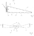
- FIG Figure 6 A further development of the invention by means of which the light output can also be optimized is shown in FIG Figure 6 shown. Only a lateral area of a sectional view of the lamp 100 can be seen here, it being possible to see that the light-guiding element 10 now has a changing thickness.
- this is wedge-shaped starting from the center or is designed in such a way that the thickness tapers starting from the side surface 11 towards the center of the light guide element 10.
- This measure can be used, for example, to optimize homogeneous light emission over the entire flat side of the light guide element 10.
- the wedge-shaped structure takes into account that the light coupled in from the side by the lighting means 21 is already partially emitted again via the underside 12 on the way to the center.
- the tapering cross-sectional shape leads to the fact that the efficiency of the coupling out is increased towards the center.
- light is emitted homogeneously over the entire surface of the light guide element 10.
- additional structures 19 can be provided which have a Deflecting incident light beams in such a way that they are emitted over the underside.
- FIG. 3 shows a further development of the luminaire 100 according to the invention described so far, which consists in that an additional light source 50 is arranged in the center of the light guide element 10.
- an additional light source 50 is arranged in the center of the light guide element 10.
- it is a single high-power LED 51, which is individually assigned its own optics 55, which serve to concentrate the light emitted by the LED 51 in the desired manner on an area below the lamp 100.
- This additional light source 50 is provided in this case to emit very concentrated light in order to specifically highlight the corresponding area in the event of emergency lighting.
- the further illuminants 20 arranged on the outer circumference of the light guide element 10 can then in turn be optionally activated in order to adapt the light distribution to the installation situation.
- an emergency light is thus made available which is very variable with regard to the light output and can thus be adapted to different installation situations.
- the risk of glare from excessively high luminance levels can also be avoided.
Landscapes
- Physics & Mathematics (AREA)
- General Physics & Mathematics (AREA)
- Optics & Photonics (AREA)
- Engineering & Computer Science (AREA)
- General Engineering & Computer Science (AREA)
- Non-Portable Lighting Devices Or Systems Thereof (AREA)
Abstract
Description
- Die vorliegende Erfindung betrifft eine Leuchte, insbesondere eine Notlichtleuchte, deren Lichtverteilung an die Montagesituation und Anwendung variabel angepasst werden kann. Je nach Bedarf kann eine symmetrische oder eine asymmetrische Wegbeleuchtung, bzw. eine Flächenbeleuchtung realisiert werden.
- In der Sicherheitsbeleuchtung kommen üblicherweise kleine, kompakte Leuchten zum Einsatz, die unterschiedliche Aufgaben erfüllen müssen. Diese Leuchten werden meist als Anbau- oder Einbauleuchte an bzw. in der Decke eines Raums montiert, in seltenen Situationen kann auch ein Wandanbau vorgesehen sein.
- Die Sicherheitsbeleuchtung soll hierbei verschiedene Aufgaben erfüllen. Eine wesentliche Aufgabe besteht bspw. in der Beleuchtung eines Fluchtwegs, wobei die Sicherheitsbeleuchtung dann dazu dient, bspw. einen als Fluchtweg vorgesehenen Gang oder Bereich derart auszuleuchten, dass im Falle eines Notzustands Personen sich orientieren bzw. zurechtfinden und den Fluchtweg nutzen können. Im Falle einer derartigen Fluchtwegbeleuchtung wird dann eher eine lineare Lichtverteilung für das abgegebene Licht benötigt, da in diesem Fall die Sicherheitsleuchte bspw. in der Mitte eines länglichen zu beleuchtenden Bereichs angeordnet ist.
- Zur Sicherheitsbeleuchtung zählt weiterhin auch eine sog. Antipanikbeleuchtung oder die Funktion, besondere Einrichtungen gezielt hervorzuheben. Bei diesen Einrichtungen kann es sich bspw. um Fluchtwegtüren oder Feuerlöscher handeln, die wiederum in einem Notzustand zweifelsfrei erkennbar sein sollten. Für diese Aufgabenstellungen wird dann jedoch eher ein flächiges Licht oder ein auf einen bestimmten Bereich gerichtetes Akzentlicht benötigt.
- Letztendlich werden für Notlichtleuchten also unterschiedliche Lichtverteilungen benötigt, was dadurch ermöglicht wird, dass verschiedene Optiken zur Verfügung gestellt werden. Bereits bei Bestellung einer Leuchte muss der Verbraucher also wissen, für welche spätere Aufgabenstellung die Notlichtleuchte gedacht ist und dann eine Leuchte mit einer der gewünschten Lichtverteilung entsprechenden Optik wählen.
- Eine weitere Eigenschaft bekannter Notlichtleuchten besteht darin, dass diese zum Reduzieren des Energieverbrauchs in der Regel lediglich wenige Lichtquellen aufweisen. Üblicherweise kommen ein oder zwei sog. High-Power-LEDs zum Einsatz, wobei dann das Licht dieser Hochleistungslichtquellen mit Hilfe einer Linse in die gewünschte Richtung gelenkt wird. Da bei einem derartigen Konzept eine nahezu punktförmige Lichtquelle zum Einsatz kommt, bedeutet dies, das verhältnismäßig hohe Leuchtdichten auftreten, sodass die Gefahr einer Blendung für Beobachter verhältnismäßig groß ist.
- Der vorliegenden Erfindung liegt die Aufgabenstellung zugrunde, die oben genannten Nachteile für bekannte Notlichtleuchten weitestgehend zu vermeiden. Insbesondere soll die Möglichkeit bestehen, die Lichtverteilung variabel an den tatsächlichen Einsatzort anpassen zu können. Weiterhin sollte idealerweise die Blendwirkung durch das von der Leuchte abgegebene Licht reduziert werden.
- Die Aufgabe wird durch eine Leuchte, welche die Merkmale des Anspruchs 1 aufweist, gelöst. Vorteilhafte Weiterbildungen der Erfindung sind Gegenstand der abhängigen Ansprüche.
- Die erfindungsgemäße Lösung beruht auf dem Gedanken, zur Abgabe des von den Leuchtmitteln der Leuchte erzeugten Lichts ein plattenförmiges Lichtleitelement zu verwenden, welches dazu ausgebildet ist, Licht, welches an Umfangsflächen des Lichtleitelements in dieses eingestrahlt wird, über eine Flachseite abzustrahlen. Dabei kommen mindestens zwei Leuchtmittel oder Leuchtmittelgruppen zum Einsatz, welche an unterschiedlichen Bereichen des Außenumfangs des Lichtleitelements angeordnet sind und somit aus jeweils unterschiedlichen Richtungen Licht in dieses einstrahlen. Zur Einstellung einer gewünschten Verteilung des von dem Lichtleitelement und damit von der Leuchte abgegebenen Lichts können dann die zwei Leuchtmittel oder Leuchtmittelgruppen unabhängig voneinander aktiviert werden.
- Erfindungsgemäß wird also eine Leuchte, insbesondere eine Notlichtleuchte vorgeschlagen, welche aufweist:
- ein plattenförmiges Lichtleitelement, welches dazu ausgebildet ist, Licht, welches an Umfangsflächen des Lichtleitelements in dieses eingestrahlt wird, über eine Flachseite abzustrahlen,
- Leuchtmittel, welche am Außenumfang des Lichtleitelements angeordnet und dazu ausgebildet sind, Licht über die Umfangsflächen des Lichtleitelements in dieses einzustrahlen,
- Durch wahlweises Aktivieren der verschiedenen Leuchtmittel bzw. Leuchtmittelgruppen kann also die Lichtverteilung des von der Leuchte insgesamt abgegebenen Lichts eingestellt werden, sodass die Lichtabstrahleigenschaften an den jeweiligen Einsatzort der Leuchte individuell angepasst werden können. Ein weiterer Vorteil der erfindungsgemäßen Lösung besteht ferner darin, dass durch die Nutzung des Lichtleitelements eine verhältnismäßig große Fläche (im Vergleich zu den punktförmigen Lichtquellen) zur Verfügung steht, über die Licht abgegeben wird. Die Leuchtdichte wird in diesem Fall deutlich reduziert und die Gefahr einer Blendung wird vermieden.
- Vorzugsweise weist das Lichtleitelement der erfindungsgemäßen Leuchte an seiner zur Lichtabstrahlung vorgesehenen Flachseite Lichtauskoppelstrukturen auf. Diese können bspw. durch eine erhabene, gitterartige Struktur an der entsprechenden Flachseite des Lichtleitelements gebildet sein. Auch geeignet ausgebildete Vertiefungen zur Lichtauskopplung wären denkbar. Die Bereiche der gitterartigen Struktur können dabei einen im wesentlichen rechteckigen Querschnitt aufweisen, wobei in diesem Fall dann vorzugsweise die senkrecht zur Flachseite des Lichtleitelements orientierten Seitenwände der gitterartigen Struktur einen Lichtaustritt ermöglichen. Auch im wesentlichen linsenartige, insbesondere konvexe Querschnitte für die gitterartige Struktur wären denkbar.
- Das Lichtleitelement kann eine rechteckige, insbesondere eine quadratische Form aufweisen, wobei in diesem Fall vorzugsweise zumindest zwei Leuchtmittel oder Leuchtmittelgruppen an zwei getrennten Seitenflächen des Umfangs des Lichtleitelements angeordnet sind. Vorzugsweise sind an allen vier Seitenflächen des Lichtleitelements jeweils unabhängig aktivierbare Leuchtmittel oder Leuchtmittelgruppen vorgesehen.
- Allerdings wäre auch eine ovale, insbesondere eine kreisförmige Form des Lichtleitelements denkbar. In diesem Fall kann insbesondere vorgesehen sein, dass die jeweils unabhängig aktivierbaren Leuchtmittel oder Leuchtmittelgruppe einer n-zähligen Drehsymmetrie entsprechend am Außenumfang des Lichtleitelements angeordnet sind. Hierbei entspricht n der Anzahl der unabhängig aktivierbaren Leuchtmittel bzw. Leuchtmittelgruppen.
- Eine Optimierung der Abgabe des Lichts über das Lichtleitelement kann ferner auch dadurch erzielt werden, dass dieses eine sich verändernde Dicke aufweist. Insbesondere kann vorgesehen sein, dass das Lichtleitelement ausgehend von seinem Außenumfang eine sich in Richtung des Zentrums verjüngende Dicke aufweist. Diese Maßnahme trägt dazu bei, dass über die gesamte Fläche des Lichtleitelements im Wesentlichen effizient und gleichmäßig Licht abgegeben wird.
- Ferner kann vorgesehen sein, dass im Zentrum des Lichtleitelements eine weitere Lichtquelle angeordnet ist, deren Licht getrennt bzw. unabhängig von dem Lichtleitelement abgegeben wird. Es kann sich in diesem Fall bspw. um eine einzelne LED handeln, die dazu dient, gezielt einen Bereich unterhalb der Notlichtleuchte mit hoher Helligkeit auszuleuchten. In diesem Fall kann der Lichtquelle ein von dem Lichtleitelement getrenntes optisches Element zugeordnet sein, wobei es sich hierbei insbesondere um eine Linse handeln kann.
- Nachfolgend soll die Erfindung anhand der beiliegenden Zeichnung näher erläutert werden. Es zeigen:
- Figur 1
- eine schematische, perspektivische Darstellung einer erfindungsgemäßen Leuchte;
- Figur 2
- die zur Lichtabgabe vorgesehene Oberfläche eines bei der erfindungsgemäßen Leuchte zum Einsatz kommenden Lichtleitelements;
- Figur 3
- eine Schnittdarstellung eines ersten Ausführungsbeispiels einer erfindungsgemäßen Leuchte;
- Figur 4
- eine Schnittdarstellung eines zweiten Ausführungsbeispiels einer erfindungsgemäßen Leuchte;
- Figuren 5a - 5c
- verschiedene Lichtverteilungen, die mit Hilfe der erfindungsgemäßen Leuchte eingestellt werden können;
- Figur 6
- eine Variante zur Ausgestaltung des Lichtleitelements und
- Figur 7
- eine Weiterbildung der erfindungsgemäßen Leuchte, bei der im Zentrum des Lichtleitelements eine weitere Lichtquelle positioniert ist.
-
Figur 1 zeigt schematisch eine erfindungsgemäße Notlichtleuchte, deren Lichtverteilung angepasst werden kann. Die mit dem Bezugszeichen 100 versehene Leuchte kann als Deckenanbau- oder Deckeneinbauleuchte genutzt werden, wobei die hierfür vorgesehenen Komponenten zur Montage der Leuchte 100 in den Figuren nicht näher dargestellt sind. Das erfindungsgemäße Konzept betrifft insbesondere die Art und Weise der Lichterzeugung und Lichtabgabe und soll im Folgenden näher erläutert werden. - Eine erste wesentliche Eigenschaft der dargestellten Leuchte 100 besteht darin, dass im Vergleich zu bislang bekannten Notlichtleuchen eine verhältnismäßig große Fläche für die Lichtabgabe genutzt wird. Während bei bislang bekannten Leuchten das Licht bspw. einer Hochleistungs-LED mit Hilfe einer Linse in gewünschter Art und Weise verteilt wird, was zu verhältnismäßig hohen Leuchtdichten führt, ist bei der erfindungsgemäßen Leuchte 100 vorgesehen, durch eine deutliche Vergrößerung der Lichtabstrahlfläche die Leuchtdichten insgesamt zu reduzieren. Dies wird dadurch erreicht, dass die Leuchte 100 für die Lichtabgabe ein flächiges Lichtleitelement 10 nutzt, welches das zentrale Bauteil der Leuchte 100 darstellt. In üblicher Weise ist das Lichtleitelement 10 dazu vorgesehen, an Umfangsflächen des Lichtleitelements 10 in dieses eingestrahltes Licht mittels Totalreflexionen zu verteilen und möglichst gleichmäßig über eine Flachseite abzugeben. Im vorliegenden Fall ist das Lichtleitelement 10 quadratisch ausgeführt und weist somit vier Seitenflächen 11 am Umfang auf, welche für die Lichteinkopplung vorgesehen sind. Das Licht soll dann über die senkrecht zu den Seitenflächen 11 ausgerichtete untere Flachseite 12 abgegeben werden, wobei die hierzu vorgesehenen Maßnahmen später noch näher erläutert werden.
- An den Außenflächen 11 des Lichtleitelements 10 sind im dargestellten Ausführungsbeispiel vier getrennte Leuchtmittelgruppen 20 vorgesehen, die jeweils durch eine LED-Platine 21 mit einigen LEDs 22 gebildet werden. Die LEDs 22 sind hierbei entlang der Platine 21 derart verteilt angeordnet, dass sie möglichst gleichmäßig über die entsprechende Seitenfläche 11 des Lichtleitelements 10 Licht in dieses einstrahlen.
- Wie die Schnittdarstellung von
Figur 3 zeigt, können hierbei spezielle Maßnahmen vorgesehen sein, um die Lichteinkopplung zu optimieren. Bspw. kann vorgesehen sein, dass wie inFigur 3 angedeutet, ober- und unterhalb der LEDs 22 reflektierende Flächen 25 ausgebildet sind, die auch das unter flachen Winkeln von den LEDs 22 abgegebene Licht derart umlenken, dass dieses über die Seitenfläche 11 in das Lichtleitelement 10 eintreten kann. Alternativ oder ergänzend hierzu könnten an den Seitenflächen 11 auch spezielle linsenartige Lichteinkoppelstrukturen vorgesehen sein, die letztendlich dazu dienen sollen, das von den LEDs 22 abgegebene Licht möglichst vollständig in das Lichtleitelement 10 einzukoppeln, sodass dieses vollständig für die Lichtabgabe zur Verfügung steht. - An der zur Lichtabgabe vorgesehenen Unterseite 12 des Lichtleitelements sind dann entsprechende Auskoppelstrukturen vorgesehen, die in bekannter Weise dazu genutzt werden, das ansonsten mittels Totalreflexionen in dem Lichtleitelement 11 verteilte Licht auszukoppeln. Im dargestellten Ausführungsbeispiel ist vorgesehen, dass die Auskoppelstrukturen 15 eine gitterartige Struktur bilden, wie dies in
Figur 2 erkennbar ist. Diese gitterartige Struktur besteht im vorliegenden Fall aus erhabenen, im Querschnitt etwa rechteck-förmigen Erhebungen 17, wie sie inFigur 3 in Schnittdarstellung erkennbar sind. Diese Strukturen 17 sind vorzugsweise einstückiger Bestandteil des Lichtleitelements 10, könnten ggf. aber auch durch eine bspw. auf die Unterseite des Lichtleitelements 10 aufgeklebte Folie oder ein zusätzliches optisches Element gebildet sein. - Wesentlich ist, dass - wie anhand der Strahlenverläufe in
Figur 3 erkennbar ist - Lichtstrahlen, welche auf die plane Unterseite 12 des Lichtleitelements 10 treffen, hier totalreflektiert werden. Lichtstrahlen hingegen, die auf entsprechende Strukturen 15 bzw. 17 treffen, können in diese eintreten und über deren Seitenwände 18 das Lichtleitelement 10 verlassen. Die hier dargestellten Strukturen 15 bzw. 17 erlauben also die Abgabe eines Lichts unter verhältnismäßig steilen Winkeln (in Bezug auf eine Senkrechte auf die Unterseite 12 des Lichtleitelements 10), sodass eine breitstreuende Lichtverteilung erzielt wird. Die Gefahr einer Blendwirkung wird hierbei trotz der stark seitlichen Lichtabgabe dadurch reduziert, dass das Licht über eine verhältnismäßig große Fläche abgegeben wird, sodass die letztendlich resultierenden Leuchtdichten im Vergleich zu aus dem Stand der Technik bekannten Lösungen geringer sind. - Auch wenn die Lichtstrahlen mehrfach innerhalb des Lichtleitelements 10 totalreflektiert werden, werden Strahlen, die letztendlich das Lichtleitelement 10 über die Auskoppelstruktur 15 verlassen, nach wie vor primär in einer durch die Lichtabstrahlung der zugehörigen LED 22 vorgegebenen Richtung die Unterseite des Lichtleitelements 10 verlassen. Bei der Darstellung gemäß
Figur 3 bedeutet dies also, dass das von der hier gezeigten LED 22 stammende Licht überwiegend das Lichtleitelement 10 an dessen Unterseite nach links gerichtet verlassen wird, was der Hauptabstrahlrichtung der LED 22 entspricht. Wären LEDs 22 ausschließlich an der rechten Seite des Lichtleitelements 10 angeordnet, so würde sich eine Lichtverteilung des letztendlich abgegebenen Lichts ergeben, wie sie inFigur 5a schematisch dargestellt ist. In diesem Fall wird also eine asymmetrisch nach links gerichtete Lichtabstrahlung erzielt, die bspw. dazu genutzt werden könnte, bei entsprechender Anordnung der Notlichtleuchte 10 gezielt einen Bereich schräg unterhalb der Leuchte 100 zu beleuchten. Dieser Bereich könnte damit gezielt aufgehellt oder hervorgehoben werden, was dann sinnvoll ist, wenn es sich hierbei um die Tür eines Fluchtweges oder um einen Feuerlöscher handelt, sodass diese Objekte für Personen auch im Falle eines Notzustands zweifelsfrei erkennbar sind. - Bei der erfindungsgemäßen Leuchte ist allerdings wie bereits erwähnt vorgesehen, dass an allen vier Seitenflächen 11 des Lichtleitelements 10 Leuchtmittel 20 angeordnet sind. Erfindungsgemäß können diese vier Leuchtmittel-Gruppen 21 nunmehr unabhängig voneinander aktiviert bzw. deaktiviert werden, sodass durch entsprechendes Kombinieren der aktivierten Leuchtmittel 20 die Lichtverteilung des von der Leuchte 100 insgesamt abgegebenen Lichts angepasst werden kann.
- Werden bspw. zwei einander gegenüberliegende Leuchtmittelgruppen aktiviert, so ergibt sich abweichend von der in
Figur 5a dargestellten Lichtverteilung nunmehr eine symmetrische Lichtverteilung des insgesamt abgegebenen Lichts, wie sie inFigur 5b dargestellt ist. Es handelt sich um eine mehr oder weniger lineare Verteilung, die aufgrund der flachen Abstrahlwinkel dazu geeignet ist, einen längeren, unterhalb der Leuchte 100 befindlichen Bereich auszuleuchten. Diese Lichtverteilung könnte dann bspw. dafür genutzt werden, einen als Fluchtweg genutzten länglichen Gang auszuleuchten. - Werden hingegen alle vier Leuchtmittel an allen vier Seitenwänden 11 des Lichtleitelements 10 aktiviert, so ergibt sich eine Lichtverteilung, wie sie in
Figur 5c dargestellt ist. Diese ist dazu geeignet, einen größeren unterhalb der Leuchte befindlichen Bereich möglichst gleichmäßig aufzuhellen und kann dementsprechend als sog. Antipanikbeleuchtung genutzt werden. - Die obigen Erläuterungen zeigen, dass also durch wahlweises Aktivieren der verschiedenen Leuchtmittel 20 die Lichtverteilung der Leuchte 100 variabel eingestellt werden kann. Damit ist die Leuchte 100 für unterschiedliche Einsatzgebiete geeignet und kann im Vergleich zu bislang bekannten Lösungen vielseitig und variabel eingesetzt werden.
- Dabei kann in einer einfachen Ausgestaltung vorgesehen sein, dass die Leuchtmittel 20 tatsächlich lediglich ein- bzw. ausgeschaltet werden können. In einer Weiterbildung kann jedoch auch vorgesehen sein, dass die Möglichkeit besteht, die Leuchtmittel-Gruppen jeweils individuell in ihrer Helligkeit einzustellen. einerseits könnte hierdurch eine Mischung der oben beschriebenen verschiedenen Lichtverteilungen erzielt werden, andererseits besteht die Möglichkeit, unabhängig von der gewählten Lichtverteilung die Menge des insgesamt abgegebenen Lichts konstant zu halten.
- Hinsichtlich der Ausgestaltung der zur Lichtauskopplung genutzten Strukturen bestehen unterschiedliche Möglichkeiten, diese zu realisieren.
Figur 4 zeigt bspw. in Schnittdarstellung eine Variante, bei der die Strukturen 15 durch linsenartige, insbesondere konvex ausgeführte Erhebungen 17 gebildet sind. Wiederum bilden diese bspw. eine Gitterstruktur wie sie inFigur 2 gezeigt ist. Die Form der Einzelstrukturen 17 eröffnet hierbei die Möglichkeit, Einfluss darauf zu nehmen, unter welchen Winkeln gegenüber der Senkrechten auf das Lichtleitelement 10 Lichtstrahlen dieses verlassen können. Während die Strukturen gemäßFigur 3 eine eher breite Verteilung erzielen, wird über die linsenartigen Vorwölbungen gemäßFigur 4 eine eher konzentrierte Lichtabgabe zur Unterseite hin erzielt, was bspw. bei größeren Montagehöhen für die Leuchte 100 sinnvoll sein kann. Letztendlich kann aber die Form der Lichtauskoppelstrukturen variabel gestaltet sein, wobei nicht nur wie in den Figuren gezeigt erhabene Strukturen zum Einsatz kommen können, sondern auch entsprechend geeignete Ausnehmungen oder Vertiefungen. Auch Prismenstrukturen oder dergleichen wären denkbar. - Ferner ist das erfindungsgemäße Konzept auch nicht darauf beschränkt, dass - wie in
Figur 1 gezeigt - an allen vier Seiten des Lichtleitelements 10 getrennt aktivierbare Leuchtmittel 20 vorgesehen sind. Auch eine Anordnung bspw. von lediglich zwei einander gegenüberliegenden Leuchtmittelgruppen 21 wäre sinnvoll, um variabel zwischen einer asymmetrischen Lichtabgabe, wie sie inFigur 5a gezeigt ist, und einer symmetrischen Lichtabgabe entsprechendFigur 5b wechseln zu können. - Weiterhin ist auch nicht erforderlich, das Lichtleitelement 10 wie in
Figur 1 gezeigt quadratisch auszugestalten. Dieses könnte auch rechteckig oder polygonal ausgeführt sein. Auch eine ovale Form oder eine Kreisform wäre denkbar. Insbesondere im Falle einer Kreisform oder einer polygonalen Form wäre dann von Vorteil, wenn die Anordnung der getrennt aktivierbaren Leuchtmittelgruppen einer n-zähligen Drehsymmetrie folgt, wobei n die Anzahl der Leuchtmittelgruppen darstellt und im Falle eines Polygons auch der Anzahl der Seitenflächen des Lichtleitelements 10 entspricht. - Eine Weiterbildung der Erfindung, durch welche die Lichtabgabe zusätzlich optimiert werden kann, ist in
Figur 6 gezeigt. Erkennbar ist hierbei nur ein seitlicher Bereich einer Schnittdarstellung der Leuchte 100, wobei erkennbar ist, dass das Lichtleitelement 10 nunmehr eine sich verändernde Dicke aufweist. Insbesondere ist dieses ausgehend vom Zentrum keilförmig ausgebildet bzw. derart ausgeführt, dass sich die Dicke ausgehend von der Seitenfläche 11 zum Zentrum des Lichtleitelements 10 hin verjüngt. Diese Maßnahme kann bspw. dazu genutzt werden, eine homogene Lichtabgabe über die gesamte Flachseite des Lichtleitelements 10 zu optimieren. Die keilförmige Struktur berücksichtigt hierbei, dass von den Leuchtmitteln 21 seitlich eingekoppeltes Licht auf dem Weg zum Zentrum hin bereits teilweise wieder über die Unterseite 12 abgegeben wird. Die sich verjüngende Querschnittsform führt hierbei dazu, dass zum Zentrum hin die Effizienz der Auskopplung erhöht wird. Letztendlich wird über die gesamte Fläche des Lichtleitelements 10 hinweg homogen Licht abgegeben. - Ferner können wie in
Figur 6 gezeigt, an der zur Lichtabgabe vorgesehenen Oberseite des Lichtleitelements 10 zusätzliche Strukturen 19 vorgesehen sein, die eine Umlenkung auftreffender Lichtstrahlen derart bewirken, dass diese über die Unterseite hin abgegeben werden. -
Figur 7 zeigt schließlich eine Weiterbildung der bislang beschriebenen erfindungsgemäßen Leuchte 100, die darin besteht, das im Zentrum des Lichtleitelements 10 eine zusätzliche Lichtquelle 50 angeordnet ist. Es handelt sich in diesem Fall um eine einzelne Hochleistungs-LED 51, der individuell eine eigene Optik 55 zugeordnet ist, die dazu dient, das von der LED 51 abgegebene Licht in gewünschter Weise auf einen unterhalb der Leuchte 100 liegenden Bereich zu konzentrieren. Diese zusätzliche Lichtquelle 50 ist in diesem Fall dazu vorgesehen, sehr konzentriert Licht abzugeben, um den entsprechenden Bereich im Falle einer Notbeleuchtung gezielt hervorzuheben. Die weiteren, am Außenumfang des Lichtleitelements 10 angeordneten Leuchtmittel 20 können dann wiederum wahlweise aktiviert werden, um die Lichtverteilung an die Montagesituation anzupassen. - Insgesamt wird somit eine Notlichtleuchte zur Verfügung gestellt, welche sehr variabel hinsichtlich der Lichtabgabe ist und damit an unterschiedliche Montagesituationen angepasst werden kann. Durch die Vergrößerung der Lichtabstrahlfläche kann weiterhin die Gefahr einer Blendung durch zu hohe Leuchtdichten vermieden werden.
und wobei die zumindest zwei Leuchtmittel oder Leuchtmittelgruppen unabhängig voneinander aktivierbar sind, um eine Verteilung des von dem Lichtleitelement abgegebenen Lichts einstellen zu können.
Claims (15)
- Leuchte (100), insbesondere Notlichtleuchte, aufweisend:• ein plattenförmiges Lichtleitelement (10), welches dazu ausgebildet ist, Licht, welches an Umfangsflächen (11) des Lichtleitelements (10) in dieses eingestrahlt wird, über eine Flachseite (12) abzustrahlen,• Leuchtmittel (20), welche am Außenumfang des Lichtleitelements (10) angeordnet und dazu ausgebildet sind, Licht über die Umfangsflächen (11) des Lichtleitelements (10) in dieses einzustrahlen,wobei die Leuchtmittel (20) zumindest zwei Leuchtmittel (22) oder Leuchtmittelgruppen (21) umfassen, welche an unterschiedlichen Bereichen des Außenumfangs des Lichtleitelements (10) angeordnet sind und aus jeweils unterschiedlichen Richtungen Licht in das Lichtleitelement (10) einstrahlen,
und wobei die zumindest zwei Leuchtmittel (22) oder Leuchtmittelgruppen (21) unabhängig voneinander aktivierbar sind, um eine Verteilung des von dem Lichtleitelement (10) abgegebenen Lichts einstellen zu können. - Leuchte nach Anspruch 1,
dadurch gekennzeichnet,
dass das Lichtleitelement (10) an seiner zur Lichtabstrahlung vorgesehenen Flachseite (12) Lichtauskoppelstrukturen (15) aufweist. - Leuchte nach Anspruch 2,
dadurch gekennzeichnet,
dass die Lichtauskoppelstrukturen (15) durch eine erhabene oder vertiefte, gitterartige Struktur an der Flachseite (12) des Lichtleitelements (10) gebildet sind. - Leuchte nach Anspruch 3,
dadurch gekennzeichnet,
dass Bereiche (17) der gitterartigen Struktur einen im Wesentlichen rechteckigen Querschnitt aufweisen, wobei die senkrecht zur Flachseite (12) des Lichtleitelements (10) orientierte Seitenwände (18) der gitterartigen Struktur einen Lichtaustritt ermöglichen. - Leuchte nach Anspruch 3,
dadurch gekennzeichnet,
dass Bereiche der gitterartigen Struktur einen im Wesentlichen linsenartigen, insbesondere konvexen Querschnitt aufweisen. - Leuchte nach einem der vorherigen Ansprüche,
dadurch gekennzeichnet,
dass das Lichtleitelement (10) eine rechteckige, insbesondere eine quadratische Form aufweist, wobei die zumindest zwei Leuchtmittel (22) oder Leuchtmittelgruppen (21) an zwei getrennten Seitenflächen (11) des Umfangs des Lichtleitelements (10) angeordnet sind. - Leuchte nach Anspruch 6,
dadurch gekennzeichnet,
dass an allen vier Seitenflächen (11) des Lichtleitelements (10) jeweils unabhängig aktivierbare Leuchtmittel (22) oder Leuchtmittelgruppen (21) angeordnet sind. - Leuchte nach einem der Ansprüche 1 bis 5,
dadurch gekennzeichnet,
dass das Lichtleitelement (10) die Form eines n-Polygons aufweist. - Leuchte nach einem der Ansprüche 1 bis 5,
dadurch gekennzeichnet,
dass das Lichtleitelement (10) eine ovale, insbesondere eine kreisförmige Form aufweist. - Leuchte nach Anspruch 8 oder 9,
dadurch gekennzeichnet,
dass die jeweils unabhängig aktivierbaren Leuchtmittel (22) oder Leuchtmittelgruppen (21) einer n-zähligen Drehsymmetrie entsprechend am Außenumfang des Lichtleitelements (10) angeordnet sind. - Leuchte nach einem der vorherigen Ansprüche,
dadurch gekennzeichnet,
dass die Leuchtmittel (22) oder Leuchtmittelgruppen (21) in ihrer Helligkeit einstellbar sind. - Leuchte nach einem der vorherigen Ansprüche,
dadurch gekennzeichnet,
dass das Lichtleitelement (10) eine sich verändernde Dicke aufweist, insbesondere ausgehend von seinem Außenumfang eine sich in Richtung des Zentrums verjüngende Dicke. - Leuchte nach einem der vorherigen Ansprüche,
dadurch gekennzeichnet,
dass im Zentrum des Lichtleitelements (10) eine weitere Lichtquelle (50) angeordnet ist, deren Licht unabhängig von dem Lichtleitelement (10) abgegeben wird. - Leuchte nach Anspruch 13,
dadurch gekennzeichnet,
dass der Lichtquelle (50) ein von dem Lichtleitelement (10) getrenntes optisches Element (55) zugeordnet ist. - Leuchte nach Anspruch 14,
dadurch gekennzeichnet,
dass das optische Element (55) durch eine Linse gebildet ist.
Applications Claiming Priority (1)
| Application Number | Priority Date | Filing Date | Title |
|---|---|---|---|
| DE102019119449.0A DE102019119449A1 (de) | 2019-07-18 | 2019-07-18 | Notlichtleuchte |
Publications (2)
| Publication Number | Publication Date |
|---|---|
| EP3767159A1 true EP3767159A1 (de) | 2021-01-20 |
| EP3767159B1 EP3767159B1 (de) | 2022-11-09 |
Family
ID=71574979
Family Applications (1)
| Application Number | Title | Priority Date | Filing Date |
|---|---|---|---|
| EP20184902.3A Active EP3767159B1 (de) | 2019-07-18 | 2020-07-09 | Notlichtleuchte |
Country Status (3)
| Country | Link |
|---|---|
| EP (1) | EP3767159B1 (de) |
| AT (1) | AT18290U1 (de) |
| DE (1) | DE102019119449A1 (de) |
Citations (10)
| Publication number | Priority date | Publication date | Assignee | Title |
|---|---|---|---|---|
| JPH06324331A (ja) * | 1993-05-11 | 1994-11-25 | Seiko Epson Corp | 液晶表示装置 |
| WO2001050444A1 (en) * | 2000-01-06 | 2001-07-12 | Koninklijke Philips Electronics N.V. | Luminaire and light-emitting panel |
| US20080157009A1 (en) * | 2006-11-28 | 2008-07-03 | Patent-Treuhand-Gesellschaft Fur Elektrische Gluhlampen Mbh | Device for emitting electromagnetic radiation and display device |
| US20090161355A1 (en) * | 2007-12-19 | 2009-06-25 | Fu Zhun Precision Industry (Shen Zhen) Co., Ltd. | White light illuminator and reading lamp using the same |
| US20110025229A1 (en) * | 2009-07-31 | 2011-02-03 | Mau-Shiun Yeh | Multi-function planar light source illumination lamp |
| WO2012173787A1 (en) * | 2011-06-14 | 2012-12-20 | Osram Sylvania Inc. | Edge-lit light panel having a downlight within a lined indentation in the panel |
| FR2989152A1 (fr) * | 2012-04-04 | 2013-10-11 | Cooper Technologies Co | Luminaire d'eclairage de securite |
| WO2014203725A1 (ja) * | 2013-06-20 | 2014-12-24 | コニカミノルタ株式会社 | 照明装置 |
| US20150316707A1 (en) * | 2012-12-18 | 2015-11-05 | Koninklijke Philips N.V. | Lighting strip, lighting system, panel support element and modular panel system |
| US20180195705A1 (en) * | 2013-08-27 | 2018-07-12 | Eaton Intelligent Power Limited | Edge-lit lighting device |
Family Cites Families (11)
| Publication number | Priority date | Publication date | Assignee | Title |
|---|---|---|---|---|
| JPH1186620A (ja) * | 1997-07-07 | 1999-03-30 | Seiko Epson Corp | 照明装置および掲示板装置 |
| TWI246573B (en) * | 2003-04-14 | 2006-01-01 | Toppoly Optoelectronics Corp | Light emitting diode array illuminant and backlight module by using the same |
| EP1666933A1 (de) * | 2004-12-02 | 2006-06-07 | Asulab S.A. | Optische Vorrichtung mit Doppelbeleuchtungsfunktion und bildliche Formung |
| US8740443B2 (en) * | 2006-07-03 | 2014-06-03 | Core Wireless Licensing S.A.R.L. | Changing graphics in an apparatus including user interface illumination |
| DE102009005351A1 (de) * | 2008-01-18 | 2009-08-13 | Osram Sylvania Inc., Danvers | Lichtleiter für eine Lampe |
| WO2012154342A2 (en) * | 2011-05-06 | 2012-11-15 | Rambus Inc. | Lighting assembly |
| JP2013084557A (ja) * | 2011-07-21 | 2013-05-09 | Rohm Co Ltd | 照明装置 |
| US20170052310A1 (en) * | 2015-08-17 | 2017-02-23 | Ledyoung Technology Corporation | Light-emitting signboard |
| DE102017114268B4 (de) * | 2017-06-27 | 2023-06-22 | Lisa Dräxlmaier GmbH | Leuchtvorrichtung für fahrzeuganwendungen |
| JP6402812B1 (ja) * | 2017-08-10 | 2018-10-10 | オムロン株式会社 | 表示装置及び導光板 |
| DE102018002753B4 (de) * | 2018-04-06 | 2025-10-23 | Diehl Aerospace Gmbh | Flächenleuchte mit integrierter Notbeleuchtung, und Innenraumabschnitt |
-
2019
- 2019-07-18 DE DE102019119449.0A patent/DE102019119449A1/de not_active Withdrawn
- 2019-12-19 AT ATGM50238/2019U patent/AT18290U1/de unknown
-
2020
- 2020-07-09 EP EP20184902.3A patent/EP3767159B1/de active Active
Patent Citations (10)
| Publication number | Priority date | Publication date | Assignee | Title |
|---|---|---|---|---|
| JPH06324331A (ja) * | 1993-05-11 | 1994-11-25 | Seiko Epson Corp | 液晶表示装置 |
| WO2001050444A1 (en) * | 2000-01-06 | 2001-07-12 | Koninklijke Philips Electronics N.V. | Luminaire and light-emitting panel |
| US20080157009A1 (en) * | 2006-11-28 | 2008-07-03 | Patent-Treuhand-Gesellschaft Fur Elektrische Gluhlampen Mbh | Device for emitting electromagnetic radiation and display device |
| US20090161355A1 (en) * | 2007-12-19 | 2009-06-25 | Fu Zhun Precision Industry (Shen Zhen) Co., Ltd. | White light illuminator and reading lamp using the same |
| US20110025229A1 (en) * | 2009-07-31 | 2011-02-03 | Mau-Shiun Yeh | Multi-function planar light source illumination lamp |
| WO2012173787A1 (en) * | 2011-06-14 | 2012-12-20 | Osram Sylvania Inc. | Edge-lit light panel having a downlight within a lined indentation in the panel |
| FR2989152A1 (fr) * | 2012-04-04 | 2013-10-11 | Cooper Technologies Co | Luminaire d'eclairage de securite |
| US20150316707A1 (en) * | 2012-12-18 | 2015-11-05 | Koninklijke Philips N.V. | Lighting strip, lighting system, panel support element and modular panel system |
| WO2014203725A1 (ja) * | 2013-06-20 | 2014-12-24 | コニカミノルタ株式会社 | 照明装置 |
| US20180195705A1 (en) * | 2013-08-27 | 2018-07-12 | Eaton Intelligent Power Limited | Edge-lit lighting device |
Also Published As
| Publication number | Publication date |
|---|---|
| EP3767159B1 (de) | 2022-11-09 |
| AT18290U1 (de) | 2024-08-15 |
| DE102019119449A1 (de) | 2021-01-21 |
Similar Documents
| Publication | Publication Date | Title |
|---|---|---|
| EP0846915B1 (de) | Innenraumleuchte | |
| EP2729838A1 (de) | Optisches element | |
| WO2015091444A1 (de) | Optisches element, sowie anordnung zur lichtabgabe | |
| DE102007040573A1 (de) | Beleuchtungsvorrichtung | |
| EP2644976A1 (de) | Leuchte mit Lichtabstrahlung in einen Randbereich | |
| EP2796769B1 (de) | LED-Leuchte mit einer Lichtleiter-Anordnung | |
| DE102017216259A1 (de) | Anordnung zur Lichtabgabe | |
| EP2295851B1 (de) | Lichtbeeinflussungselement | |
| EP3767159B1 (de) | Notlichtleuchte | |
| EP1843086A1 (de) | Reflektorleuchte | |
| AT15345U1 (de) | Leuchtenanordnung sowie Leuchte | |
| EP3832194B1 (de) | Optisches system zum beeinflussen der lichtabgabe einer länglichen lichtquelle | |
| AT17187U1 (de) | Leuchte | |
| EP3869093B1 (de) | Flächenleuchte mit direkter und indirekter lichtabgabe | |
| EP2989378B1 (de) | Led-leuchte mit unterschiedlich einstellbaren lichtverteilungen | |
| EP3591281B1 (de) | Innenraumleuchte | |
| EP0638764A1 (de) | Vorwiegend direkt strahlende Innenleuchte | |
| EP4168711B1 (de) | Anordnung zur lichtabgabe und leuchte | |
| DE102017114268B4 (de) | Leuchtvorrichtung für fahrzeuganwendungen | |
| EP4107426B1 (de) | Längliche leuchte | |
| EP2725286B1 (de) | Leuchte mit LED-Lichtquelle | |
| DE102018119606A1 (de) | Optisches Element für eine Leuchte, insbesondere Büroleuchte, sowie Leuchte | |
| EP3627042B1 (de) | Leuchte mit plattenförmigem lichtleitelement | |
| EP1843082B1 (de) | Deckenleuchte, insbesondere zur Verwendung in einem Flur | |
| EP3329178B1 (de) | Lichtleiterelement |
Legal Events
| Date | Code | Title | Description |
|---|---|---|---|
| PUAI | Public reference made under article 153(3) epc to a published international application that has entered the european phase |
Free format text: ORIGINAL CODE: 0009012 |
|
| STAA | Information on the status of an ep patent application or granted ep patent |
Free format text: STATUS: THE APPLICATION HAS BEEN PUBLISHED |
|
| AK | Designated contracting states |
Kind code of ref document: A1 Designated state(s): AL AT BE BG CH CY CZ DE DK EE ES FI FR GB GR HR HU IE IS IT LI LT LU LV MC MK MT NL NO PL PT RO RS SE SI SK SM TR |
|
| AX | Request for extension of the european patent |
Extension state: BA ME |
|
| STAA | Information on the status of an ep patent application or granted ep patent |
Free format text: STATUS: REQUEST FOR EXAMINATION WAS MADE |
|
| 17P | Request for examination filed |
Effective date: 20210401 |
|
| RBV | Designated contracting states (corrected) |
Designated state(s): AL AT BE BG CH CY CZ DE DK EE ES FI FR GB GR HR HU IE IS IT LI LT LU LV MC MK MT NL NO PL PT RO RS SE SI SK SM TR |
|
| INTG | Intention to grant announced |
Effective date: 20220527 |
|
| INTG | Intention to grant announced |
Effective date: 20220527 |
|
| GRAJ | Information related to disapproval of communication of intention to grant by the applicant or resumption of examination proceedings by the epo deleted |
Free format text: ORIGINAL CODE: EPIDOSDIGR1 |
|
| INTC | Intention to grant announced (deleted) | ||
| GRAP | Despatch of communication of intention to grant a patent |
Free format text: ORIGINAL CODE: EPIDOSNIGR1 |
|
| STAA | Information on the status of an ep patent application or granted ep patent |
Free format text: STATUS: GRANT OF PATENT IS INTENDED |
|
| GRAS | Grant fee paid |
Free format text: ORIGINAL CODE: EPIDOSNIGR3 |
|
| GRAA | (expected) grant |
Free format text: ORIGINAL CODE: 0009210 |
|
| STAA | Information on the status of an ep patent application or granted ep patent |
Free format text: STATUS: THE PATENT HAS BEEN GRANTED |
|
| INTG | Intention to grant announced |
Effective date: 20220928 |
|
| AK | Designated contracting states |
Kind code of ref document: B1 Designated state(s): AL AT BE BG CH CY CZ DE DK EE ES FI FR GB GR HR HU IE IS IT LI LT LU LV MC MK MT NL NO PL PT RO RS SE SI SK SM TR |
|
| REG | Reference to a national code |
Ref country code: GB Ref legal event code: FG4D Free format text: NOT ENGLISH |
|
| REG | Reference to a national code |
Ref country code: CH Ref legal event code: EP Ref country code: AT Ref legal event code: REF Ref document number: 1530587 Country of ref document: AT Kind code of ref document: T Effective date: 20221115 |
|
| REG | Reference to a national code |
Ref country code: DE Ref legal event code: R096 Ref document number: 502020001951 Country of ref document: DE |
|
| REG | Reference to a national code |
Ref country code: IE Ref legal event code: FG4D Free format text: LANGUAGE OF EP DOCUMENT: GERMAN |
|
| REG | Reference to a national code |
Ref country code: LT Ref legal event code: MG9D |
|
| REG | Reference to a national code |
Ref country code: NL Ref legal event code: MP Effective date: 20221109 |
|
| PG25 | Lapsed in a contracting state [announced via postgrant information from national office to epo] |
Ref country code: SE Free format text: LAPSE BECAUSE OF FAILURE TO SUBMIT A TRANSLATION OF THE DESCRIPTION OR TO PAY THE FEE WITHIN THE PRESCRIBED TIME-LIMIT Effective date: 20221109 Ref country code: PT Free format text: LAPSE BECAUSE OF FAILURE TO SUBMIT A TRANSLATION OF THE DESCRIPTION OR TO PAY THE FEE WITHIN THE PRESCRIBED TIME-LIMIT Effective date: 20230309 Ref country code: NO Free format text: LAPSE BECAUSE OF FAILURE TO SUBMIT A TRANSLATION OF THE DESCRIPTION OR TO PAY THE FEE WITHIN THE PRESCRIBED TIME-LIMIT Effective date: 20230209 Ref country code: LT Free format text: LAPSE BECAUSE OF FAILURE TO SUBMIT A TRANSLATION OF THE DESCRIPTION OR TO PAY THE FEE WITHIN THE PRESCRIBED TIME-LIMIT Effective date: 20221109 Ref country code: FI Free format text: LAPSE BECAUSE OF FAILURE TO SUBMIT A TRANSLATION OF THE DESCRIPTION OR TO PAY THE FEE WITHIN THE PRESCRIBED TIME-LIMIT Effective date: 20221109 Ref country code: ES Free format text: LAPSE BECAUSE OF FAILURE TO SUBMIT A TRANSLATION OF THE DESCRIPTION OR TO PAY THE FEE WITHIN THE PRESCRIBED TIME-LIMIT Effective date: 20221109 |
|
| PG25 | Lapsed in a contracting state [announced via postgrant information from national office to epo] |
Ref country code: RS Free format text: LAPSE BECAUSE OF FAILURE TO SUBMIT A TRANSLATION OF THE DESCRIPTION OR TO PAY THE FEE WITHIN THE PRESCRIBED TIME-LIMIT Effective date: 20221109 Ref country code: PL Free format text: LAPSE BECAUSE OF FAILURE TO SUBMIT A TRANSLATION OF THE DESCRIPTION OR TO PAY THE FEE WITHIN THE PRESCRIBED TIME-LIMIT Effective date: 20221109 Ref country code: LV Free format text: LAPSE BECAUSE OF FAILURE TO SUBMIT A TRANSLATION OF THE DESCRIPTION OR TO PAY THE FEE WITHIN THE PRESCRIBED TIME-LIMIT Effective date: 20221109 Ref country code: IS Free format text: LAPSE BECAUSE OF FAILURE TO SUBMIT A TRANSLATION OF THE DESCRIPTION OR TO PAY THE FEE WITHIN THE PRESCRIBED TIME-LIMIT Effective date: 20230309 Ref country code: HR Free format text: LAPSE BECAUSE OF FAILURE TO SUBMIT A TRANSLATION OF THE DESCRIPTION OR TO PAY THE FEE WITHIN THE PRESCRIBED TIME-LIMIT Effective date: 20221109 Ref country code: GR Free format text: LAPSE BECAUSE OF FAILURE TO SUBMIT A TRANSLATION OF THE DESCRIPTION OR TO PAY THE FEE WITHIN THE PRESCRIBED TIME-LIMIT Effective date: 20230210 |
|
| PG25 | Lapsed in a contracting state [announced via postgrant information from national office to epo] |
Ref country code: NL Free format text: LAPSE BECAUSE OF FAILURE TO SUBMIT A TRANSLATION OF THE DESCRIPTION OR TO PAY THE FEE WITHIN THE PRESCRIBED TIME-LIMIT Effective date: 20221109 |
|
| P01 | Opt-out of the competence of the unified patent court (upc) registered |
Effective date: 20230530 |
|
| PG25 | Lapsed in a contracting state [announced via postgrant information from national office to epo] |
Ref country code: SM Free format text: LAPSE BECAUSE OF FAILURE TO SUBMIT A TRANSLATION OF THE DESCRIPTION OR TO PAY THE FEE WITHIN THE PRESCRIBED TIME-LIMIT Effective date: 20221109 Ref country code: RO Free format text: LAPSE BECAUSE OF FAILURE TO SUBMIT A TRANSLATION OF THE DESCRIPTION OR TO PAY THE FEE WITHIN THE PRESCRIBED TIME-LIMIT Effective date: 20221109 Ref country code: EE Free format text: LAPSE BECAUSE OF FAILURE TO SUBMIT A TRANSLATION OF THE DESCRIPTION OR TO PAY THE FEE WITHIN THE PRESCRIBED TIME-LIMIT Effective date: 20221109 Ref country code: DK Free format text: LAPSE BECAUSE OF FAILURE TO SUBMIT A TRANSLATION OF THE DESCRIPTION OR TO PAY THE FEE WITHIN THE PRESCRIBED TIME-LIMIT Effective date: 20221109 Ref country code: CZ Free format text: LAPSE BECAUSE OF FAILURE TO SUBMIT A TRANSLATION OF THE DESCRIPTION OR TO PAY THE FEE WITHIN THE PRESCRIBED TIME-LIMIT Effective date: 20221109 |
|
| REG | Reference to a national code |
Ref country code: DE Ref legal event code: R097 Ref document number: 502020001951 Country of ref document: DE |
|
| PG25 | Lapsed in a contracting state [announced via postgrant information from national office to epo] |
Ref country code: SK Free format text: LAPSE BECAUSE OF FAILURE TO SUBMIT A TRANSLATION OF THE DESCRIPTION OR TO PAY THE FEE WITHIN THE PRESCRIBED TIME-LIMIT Effective date: 20221109 Ref country code: AL Free format text: LAPSE BECAUSE OF FAILURE TO SUBMIT A TRANSLATION OF THE DESCRIPTION OR TO PAY THE FEE WITHIN THE PRESCRIBED TIME-LIMIT Effective date: 20221109 |
|
| PLBE | No opposition filed within time limit |
Free format text: ORIGINAL CODE: 0009261 |
|
| STAA | Information on the status of an ep patent application or granted ep patent |
Free format text: STATUS: NO OPPOSITION FILED WITHIN TIME LIMIT |
|
| 26N | No opposition filed |
Effective date: 20230810 |
|
| PG25 | Lapsed in a contracting state [announced via postgrant information from national office to epo] |
Ref country code: SI Free format text: LAPSE BECAUSE OF FAILURE TO SUBMIT A TRANSLATION OF THE DESCRIPTION OR TO PAY THE FEE WITHIN THE PRESCRIBED TIME-LIMIT Effective date: 20221109 |
|
| PG25 | Lapsed in a contracting state [announced via postgrant information from national office to epo] |
Ref country code: MC Free format text: LAPSE BECAUSE OF FAILURE TO SUBMIT A TRANSLATION OF THE DESCRIPTION OR TO PAY THE FEE WITHIN THE PRESCRIBED TIME-LIMIT Effective date: 20221109 |
|
| PG25 | Lapsed in a contracting state [announced via postgrant information from national office to epo] |
Ref country code: MC Free format text: LAPSE BECAUSE OF FAILURE TO SUBMIT A TRANSLATION OF THE DESCRIPTION OR TO PAY THE FEE WITHIN THE PRESCRIBED TIME-LIMIT Effective date: 20221109 |
|
| REG | Reference to a national code |
Ref country code: CH Ref legal event code: PL |
|
| REG | Reference to a national code |
Ref country code: BE Ref legal event code: MM Effective date: 20230731 |
|
| PG25 | Lapsed in a contracting state [announced via postgrant information from national office to epo] |
Ref country code: LU Free format text: LAPSE BECAUSE OF NON-PAYMENT OF DUE FEES Effective date: 20230709 |
|
| PG25 | Lapsed in a contracting state [announced via postgrant information from national office to epo] |
Ref country code: LU Free format text: LAPSE BECAUSE OF NON-PAYMENT OF DUE FEES Effective date: 20230709 |
|
| REG | Reference to a national code |
Ref country code: IE Ref legal event code: MM4A |
|
| PG25 | Lapsed in a contracting state [announced via postgrant information from national office to epo] |
Ref country code: CH Free format text: LAPSE BECAUSE OF NON-PAYMENT OF DUE FEES Effective date: 20230731 |
|
| PG25 | Lapsed in a contracting state [announced via postgrant information from national office to epo] |
Ref country code: IT Free format text: LAPSE BECAUSE OF FAILURE TO SUBMIT A TRANSLATION OF THE DESCRIPTION OR TO PAY THE FEE WITHIN THE PRESCRIBED TIME-LIMIT Effective date: 20221109 Ref country code: BE Free format text: LAPSE BECAUSE OF NON-PAYMENT OF DUE FEES Effective date: 20230731 |
|
| PG25 | Lapsed in a contracting state [announced via postgrant information from national office to epo] |
Ref country code: IE Free format text: LAPSE BECAUSE OF NON-PAYMENT OF DUE FEES Effective date: 20230709 |
|
| PG25 | Lapsed in a contracting state [announced via postgrant information from national office to epo] |
Ref country code: IE Free format text: LAPSE BECAUSE OF NON-PAYMENT OF DUE FEES Effective date: 20230709 |
|
| PG25 | Lapsed in a contracting state [announced via postgrant information from national office to epo] |
Ref country code: BG Free format text: LAPSE BECAUSE OF FAILURE TO SUBMIT A TRANSLATION OF THE DESCRIPTION OR TO PAY THE FEE WITHIN THE PRESCRIBED TIME-LIMIT Effective date: 20221109 |
|
| PG25 | Lapsed in a contracting state [announced via postgrant information from national office to epo] |
Ref country code: BG Free format text: LAPSE BECAUSE OF FAILURE TO SUBMIT A TRANSLATION OF THE DESCRIPTION OR TO PAY THE FEE WITHIN THE PRESCRIBED TIME-LIMIT Effective date: 20221109 |
|
| PG25 | Lapsed in a contracting state [announced via postgrant information from national office to epo] |
Ref country code: CY Free format text: LAPSE BECAUSE OF FAILURE TO SUBMIT A TRANSLATION OF THE DESCRIPTION OR TO PAY THE FEE WITHIN THE PRESCRIBED TIME-LIMIT; INVALID AB INITIO Effective date: 20200709 |
|
| PG25 | Lapsed in a contracting state [announced via postgrant information from national office to epo] |
Ref country code: HU Free format text: LAPSE BECAUSE OF FAILURE TO SUBMIT A TRANSLATION OF THE DESCRIPTION OR TO PAY THE FEE WITHIN THE PRESCRIBED TIME-LIMIT; INVALID AB INITIO Effective date: 20200709 |
|
| PGFP | Annual fee paid to national office [announced via postgrant information from national office to epo] |
Ref country code: DE Payment date: 20250728 Year of fee payment: 6 |
|
| PGFP | Annual fee paid to national office [announced via postgrant information from national office to epo] |
Ref country code: GB Payment date: 20250722 Year of fee payment: 6 |
|
| PGFP | Annual fee paid to national office [announced via postgrant information from national office to epo] |
Ref country code: AT Payment date: 20251020 Year of fee payment: 5 Ref country code: FR Payment date: 20250725 Year of fee payment: 6 |
|
| PG25 | Lapsed in a contracting state [announced via postgrant information from national office to epo] |
Ref country code: TR Free format text: LAPSE BECAUSE OF FAILURE TO SUBMIT A TRANSLATION OF THE DESCRIPTION OR TO PAY THE FEE WITHIN THE PRESCRIBED TIME-LIMIT Effective date: 20221109 |